

Page 1

Chapter 4
Specifications
Page 2

Chapter 4 Contents
4-1 Hardware notes ................................................................................................................................ 4-3
4-4-1 Hardware configuration................................................................................................................... 4-3
4-1-2 Motor drive board............................................................................................................................ 4-4
(1) Feed motor drive circuit ...................................................................................................................... 4-4
(2) Paper empty detection/Cassette detection circuit............................................................................... 4-5
4-1-2 Connector board ............................................................................................................................. 4-6
4-2 Paper feeding system...................................................................................................................... 4-7
4-2-1 Paper control signals ...................................................................................................................... 4-8
4-2-2 Paper feeder’s cassette feeding ..................................................................................................... 4-9
4-2-3 Paper sensor ................................................................................................................................ 4-10
Page 3
4-1 Hardware notes
4-4-1 Hardware configuration
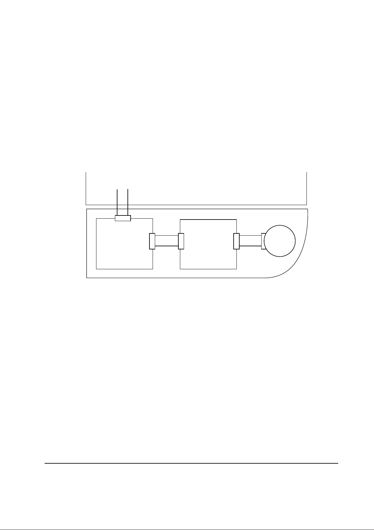
The hardware of the paper feeder PF-16 includes the connector board, motor drive board, the feed
motor, etc. The connector board is used to relay the signals between the paper feeder and the printer.
The motor drive board includes the feed motor driving circuit, paper empty detection/cassette detection circuit, etc.
Engine board
Connector board
(KP-595)
Printer
Motor drive board
Paper feeder
(KP-597)
Feed
motor
Figure 4-1-1 Hardware configuration block diagram
4-3
PF-16
Page 4

4-1-2 Motor drive board
(1) Feed motor drive circuit
The feed motor is driven by the 12 V DC supply which is obtained by down-converting the 24 V
DC supply from the printer by zener diodes DZ801 and DZ802. Two zener diodes are used in series
for compensation of the temperature response of zener diodes.
Control over the current for driving the feed motor is implemented as follows: Transistor Q803
turns on when the current flowing through resistor R805 is in excess of the predetermined value.
This in turn controls the base voltage of transistor Q801 which is connected with Q803, turning
Q801 on and disconnecting the current in the feed motor. Transistor Q801 then turns off since no
current flows through R805. Now Q801 turns on and drives the feed motor . By repetitively continuing
the above procedure, the maximum current in the feed motor is regulated and the over-current
situation is prevented.
Feed motor drive circuit
R801
R802
DZ801
DZ802
24V DC
Q801
C
Q803
E
B
C
E
R804
B
R805
Feed motor
PF-16
Figure 4-1-2 Feed motor drive circuit
4-4
Page 5

(2) Paper empty detection/Cassette detection circuit
The motor drive board mounts the sensor and switch for detection of paper emptiness and cassette
presence. Paper sensor PH801 is a photo interrupter that detects presence of paper by means of the
actuator. Cassette switch SW801 is a push switch that detects the presence of the paper cassette as
triggered by a pin.
5 V DC
Motor drive board
CPU
SENPW
PFPER*
Printer
R238
Engine board
R803R243
SW801
PH801
Actuator
Paper feeder PF-16
Pin
Paper cassette
Figure 4-1-3 Paper empty detection/Cassette detection circuit
Table 4-1-1 Paper empty detection/Cassette detection circuit signals
Signal Input/Output Function Meaning
SENPW
Input
Input Illuminates the paper sensor (LED)
only while the printer’s fan is running.
Control signal for the
paper sensor (PH801)
LED.
PFPER*
Output
H: Paper empty or no cassette
L: Paper present or cassette inserted
Detection signal for
paper cassette or paper.
4-5
PF-16
Page 6
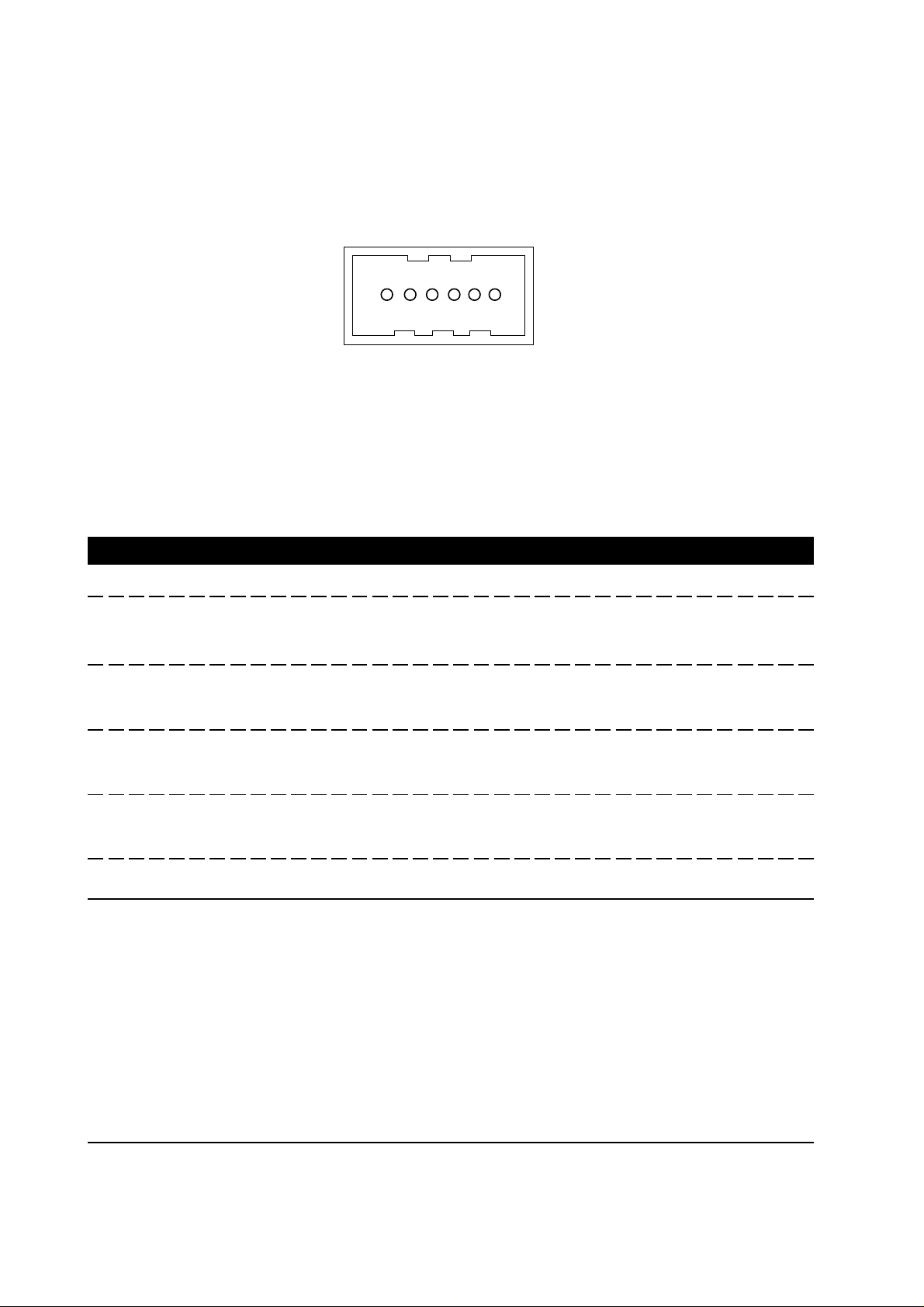
4-1-2 Connector board
The connector board mounts connector YC701 for connecting to the printer and connector YC702
for connector to the motor drive board. The diagram below shows the arrangement of the connector
pins.
1 2 3 4 5 6
YC701 viewed at the bottom
Figure 4-1-4 Connector (YC701)
Table 4-1-2 Connector (YC701) pin assignment
Pin No. Input/Output Signal Function
1
Input
24 V DC power
-
2
Input
Feed motor drive signal
L: On (Run)
H: Off (Stop)
3
Input
Control signal for LED
L: Paper or cassette is present
illumination
4
Output
Paper empty and cassette
H: Paper is empty or the cassette is present
insertion detection signal
5
6
Output
-
Paper feeder installation
signal
GND
L: Paper feeder installed
H: Paper feeder not installed
Ground
PF-16
4-6
Page 7

4-2 Paper feeding system
The paper feeding system picks up paper from the paper feeder PF-16. Paper is fed at a precise
timing in synchronization with data processing. The paper feeding system finally delivers the printed
page to either the face-down or face-up tray as manipulated by the user . The figure below shows the
components comprising the paper feeding system and the paths through which the paper travels.
Process unit
(PU-16)
Fuser unit
Feed roller
Paper feeder PF16
Figure 4-2-1 Paper feeding system diagram
4-7
PF-16
Page 8

4-2-1 Paper control signals
The following diagram shows for sensors and rollers that guide paper during printing. The printer’s
engine controller provides these signals in conjunction with the electrophotography process that is
driven by the printer’s main logic controller system.
Printer FS-600/FS-680
Engine Controller
Face-down rollers
PFSEN
PAPER*
SENPW
PFMDR*
Exit
sensor
EXITJ*
Exit rollers
Connector board
(KP-595)
Main motor
Heat Roller
Pressure
Roller
MOTDR
Drum
Transfer
roller
Motor drive board
(KP-597)
RESIDR
Regist.
clutch
Registration
rollers
RESIT*
Regist
sensor
PAPER
Paper
sensor
Cassette
switch
Paper
sensor
FEDDR*
Feed
clutch
Feed
motor
Manual
feed tray
PF-16
Paper feeder PF-16
Figure 4-2-2 Paper control system block diagram
4-8
Page 9

4-2-2 Paper feeder’s cassette feeding
The printer’s main logic controller sends the PRINT* signal to the engine controller after it has
finished processing data. The printer’s engine controller CPU then starts the main motor (MOTDR),
polygon motor, registration rollers, and the fuser heater. The engine controller then issues the
PFMDR* signal which connects the paper feeder’s feed motor power to the feed roller. The feed
roller feeds the top sheet in the paper stack in the paper feeder’s cassette towards the registration
rollers until the paper reaches the registration sensor (RESIT*). As the engine controller sends
VSREQ* to the main logic controller, the main logic controller subsequently issues VSYNC* to
activate the registration rollers, thus starting to feed paper forwards to the drum. The paper is
advanced to the drum, to the fuser unit, triggering the exit sensor (EXITJ*), and finally delivered
either to the face-down or face-up tray as manipulated by the user.
4-9
PF-16
Page 10
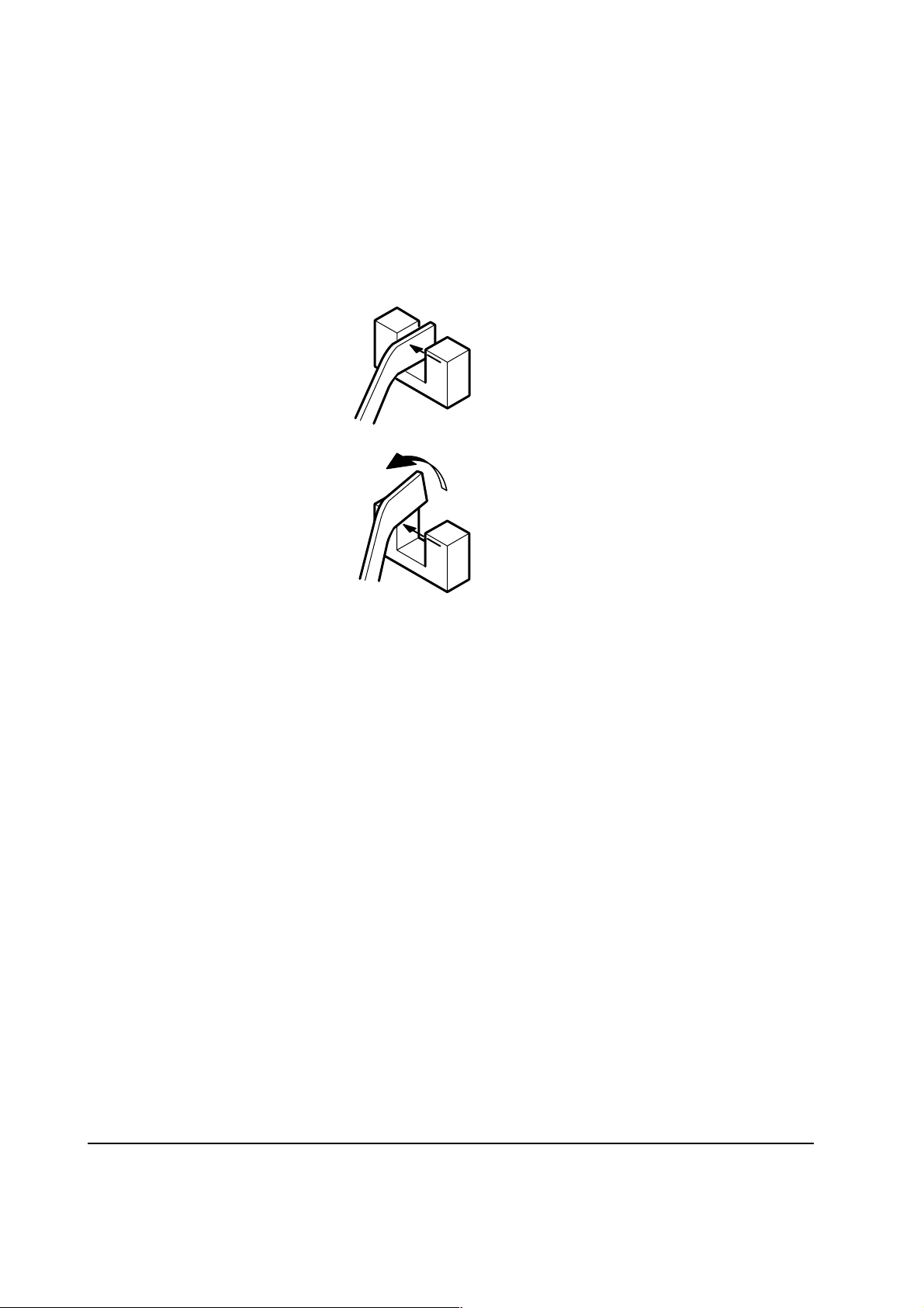
4-2-3 Paper sensor
A photo penetration type sensor is used for the paper sensor. While paper is not present as shown in
1 the reflector at one end of the sensor’s actuator is normally seated in between the photo transmitter and the sensor . While the paper is present, the reflector is pushed up by the paper and the light is
interrupted as shown in 2, thus triggering the sensor.
1
2
Figure 4-2-3 Paper sensor
PF-16
4-10
 Loading...