

Page 1

SERVICE
MANUAL
Published in Oct.’01
843C1110
Page 2

Safety precautions
This booklet provides safety warnings and precautions for our service personnel to ensure the safety of
their customers, their machines as well as themselves during maintenance activities. Service personnel
are advised to read this booklet carefully to familiarize themselves with the warnings and precautions
described here before engaging in maintenance activities.
Page 3
Safety warnings and precautions
Various symbols are used to protect our service personnel and customers from physical danger and
to prevent damage to their property. These symbols are described below:
DANGER: High risk of serious bodily injury or death may result from insufficient attention to or incorrect
compliance with warning messages using this symbol.
WARNING:Serious bodily injury or death may result from insufficient attention to or incorrect compliance
with warning messages using this symbol.
CAUTION:Bodily injury or damage to property may result from insufficient attention to or incorrect
compliance with warning messages using this symbol.
Symbols
The triangle ( ) symbol indicates a warning including danger and caution. The specific point
of attention is shown inside the symbol.
General warning.
Warning of risk of electric shock.
Warning of high temperature.
indicates a prohibited action. The specific prohibition is shown inside the symbol.
General prohibited action.
Disassembly prohibited.
indicates that action is required. The specific action required is shown inside the symbol.
General action required.
Remove the power plug from the wall outlet.
Always ground the copier.
Page 4
1. Installation Precautions
WARNING
• Do not use a power supply with a voltage other than that specified. Avoid multiple connections to
one outlet: they may cause fire or electric shock. When using an extension cable, always check
that it is adequate for the rated current. ............................................................................................
• Connect the ground wire to a suitable grounding point. Not grounding the copier may cause fire or
electric shock. Connecting the earth wire to an object not approved for the purpose may cause
explosion or electric shock. Never connect the ground cable to any of the following: gas pipes,
lightning rods, ground cables for telephone lines and water pipes or faucets not approved by the
proper authorities. .............................................................................................................................
CAUTION:
• Do not place the copier on an infirm or angled surface: the copier may tip over, causing injury. .....
• Do not install the copier in a humid or dusty place. This may cause fire or electric shock. ..............
• Do not install the copier near a radiator, heater, other heat source or near flammable material.
This may cause fire. ..........................................................................................................................
• Allow sufficient space around the copier to allow the ventilation grills to keep the machine as cool
as possible. Insufficient ventilation may cause heat buildup and poor copying performance. ..........
• Always handle the machine by the correct locations when moving it. ..............................................
• Always use anti-toppling and locking devices on copiers so equipped. Failure to do this may
cause the copier to move unexpectedly or topple, leading to injury..................................................
• Avoid inhaling toner or developer excessively. Protect the eyes. If toner or developer is
accidentally ingested, drink a lot of water to dilute it in the stomach and obtain medical attention
immediately. If it gets into the eyes, rinse immediately with copious amounts of water and obtain
medical attention. ..............................................................................................................................
• Advice customers that they must always follow the safety warnings and precautions in the copier’s
instruction handbook. ........................................................................................................................
Page 5
2. Precautions for Maintenance
WARNING
• Always remove the power plug from the wall outlet before starting machine disassembly...............
• Always follow the procedures for maintenance described in the service manual and other related
brochures. .........................................................................................................................................
• Under no circumstances attempt to bypass or disable safety features including safety
mechanisms and protective circuits. .................................................................................................
• Always use parts having the correct specifications...........................................................................
• Always use the thermostat or thermal fuse specified in the service manual or other related
brochure when replacing them. Using a piece of wire, for example, could lead to fire or other
serious accident. ...............................................................................................................................
• When the service manual or other serious brochure specifies a distance or gap for installation of a
part, always use the correct scale and measure carefully. ...............................................................
• Always check that the copier is correctly connected to an outlet with a ground connection. ............
• Check that the power cable covering is free of damage. Check that the power plug is dust-free. If
it is dirty, clean it to remove the risk of fire or electric shock. ............................................................
• Never attempt to disassemble the optical unit in machines using lasers. Leaking laser light may
damage eyesight. ..............................................................................................................................
• Handle the charger sections with care. They are charged to high potentials and may cause
electric shock if handled improperly. .................................................................................................
CAUTION
• Wear safe clothing. If wearing loose clothing or accessories such as ties, make sure they are
safely secured so they will not be caught in rotating sections...........................................................
• Use utmost caution when working on a powered machine. Keep away from chains and belts. .......
• Handle the fixing section with care to avoid burns as it can be extremely hot. .................................
• Check that the fixing unit thermistor, heat and press rollers are clean. Dirt on them can cause
abnormally high temperatures...........................................................................................................
• Do not remove the ozone filter, if any, from the copier except for routine replacement....................
Page 6
• Do not pull on the AC power cord or connector wires on high-voltage components when removing
them; always hold the plug itself. ......................................................................................................
• Do not route the power cable where it may be stood on or trapped. If necessary, protect it with a
cable cover or other appropriate item. ..............................................................................................
• Treat the ends of the wire carefully when installing a new charger wire to avoid electric leaks........
• Remove toner completely from electronic components. ...................................................................
• Run wire harnesses carefully so that wires will not be trapped or damaged. ...................................
• After maintenance, always check that all the parts, screws, connectors and wires that were
removed, have been refitted correctly. Special attention should be paid to any forgotten
connector, trapped wire and missing screws. ..................................................................................
• Check that all the caution labels that should be present on the machine according to the
instruction handbook are clean and not peeling. Replace with new ones if necessary. ...................
• Handle greases and solvents with care by following the instructions below: ....................................
· Use only a small amount of solvent at a time, being careful not to spill. Wipe spills off completely.
· Ventilate the room well while using grease or solvents.
· Allow applied solvents to evaporate completely before refitting the covers or turning the main
switch on.
· Always wash hands afterwards.
• Never dispose of toner or toner bottles in fire. Toner may cause sparks when exposed directly to
fire in a furnace, etc...........................................................................................................................
• Should smoke be seen coming from the copier, remove the power plug from the wall outlet
immediately. ......................................................................................................................................
3. Miscellaneous
WARNING
• Never attempt to heat the drum or expose it to any organic solvents such as alcohol, other than
the specified refiner; it may generate toxic gas. ................................................................................
Page 7

CONTENTS
1-1 Specifications
1-1-1 Specifications ....................................................................................................................................... 1-1-1
1-1-2 Parts names ......................................................................................................................................... 1-1-2
1-1-3 Machine cross section .......................................................................................................................... 1-1-3
1-1-4 Drive system ........................................................................................................................................ 1-1-4
1-2 Installation
1-2-1 Unpacking ............................................................................................................................................ 1-2-1
(1) Unpacking ....................................................................................................................................... 1-2-1
(2) Removing tapes and metal fittings ................................................................................................. 1-2-2
1-2-2 Installing the mailbox (option) .............................................................................................................. 1-2-5
1-3 Maintenance Mode
1-3-1 Maintenance mode ............................................................................................................................... 1-3-1
1-4 Troubleshooting
1-4-1 Paper misfeed detection ...................................................................................................................... 1-4-1
(1) Paper misfeed detection ................................................................................................................. 1-4-1
(2) Paper misfeed detection conditions ................................................................................................ 1-4-1
(3) Paper misfeeds ............................................................................................................................... 1-4-5
1-4-2 Self-diagnosis ....................................................................................................................................... 1-4-7
(1) Self-diagnostic function .................................................................................................................. 1-4-7
(2) Self-diagnostic codes ..................................................................................................................... 1-4-7
1-4-3 Electrical problems ............................................................................................................................. 1-4-10
(1) The paper conveying motor does not operate (C801). ................................................................. 1-4-10
(2) The front jogger motor does not operate (C817). ......................................................................... 1-4-10
(3) The rear jogger motor does not operate (C818). .......................................................................... 1-4-10
(4) The tray elevation motor does not operate (C814). ...................................................................... 1-4-10
(5) The front stapler motor does not operate (C821). ........................................................................ 1-4-10
(6) The rear stapler motor does not operate (C822). ......................................................................... 1-4-11
(7) The paper conveying belt clutch does not operate. ...................................................................... 1-4-11
(8) The paddle clutch does not operate. ............................................................................................ 1-4-11
(9) The punch clutch does not operate. ............................................................................................. 1-4-11
(10) The trailing edge press solenoid does not operate. ...................................................................... 1-4-11
(11) Feedshift solenoid 1 does not operate. ........................................................................................ 1-4-11
(12) Feedshift solenoid 2 does not operate. ........................................................................................ 1-4-12
(13) Paddle solenoid 1 does not operate. ............................................................................................ 1-4-12
(14) Paddle solenoid 2 does not operate. ............................................................................................ 1-4-12
(15) Paddle solenoid 3 does not operate. ............................................................................................ 1-4-12
(16) The rotating plate solenoid does not operate. .............................................................................. 1-4-12
(17) The drive switching solenoid does not operate. ........................................................................... 1-4-12
(18) The punch pattern solenoid does not operate. ............................................................................. 1-4-13
(19) The pressure switching solenoid does not operate. ..................................................................... 1-4-13
(20) Forwarding solenoid does not operate. ........................................................................................ 1-4-13
(21) Paper jams when the main switch is turned on. ........................................................................... 1-4-13
(22) “Out of staples. (Front) Add staples.” or “Out of staples. (Rear) Add staples.” is displayed
when the main switch is turned on. .............................................................................................. 1-4-14
1-4-4 Mechanical problems ......................................................................................................................... 1-4-15
(1) No paper feed. .............................................................................................................................. 1-4-15
(2) No paper ejection to the sort or non-sort trays. ............................................................................ 1-4-15
(3) Paper jams. .................................................................................................................................. 1-4-15
(4) Abnormal noise is heard. .............................................................................................................. 1-4-15
1-1-1
3C1
Page 8

3C1
1-5 Assembly and Disassembly
1-5-1 Precautions for assembly and disassembly ......................................................................................... 1-5-1
(1) Precautions ..................................................................................................................................... 1-5-1
1-5-2 Procedure for assembly and disassembly ........................................................................................... 1-5-1
(1) Detaching and refitting the static eliminator brushes ...................................................................... 1-5-1
(2) Detaching and refitting the punch unit ............................................................................................ 1-5-2
(3) Adjusting the center of the punch holes ......................................................................................... 1-5-3
(4) Adjusting paddle clutch turn-on timing ............................................................................................ 1-5-4
2-1 Mechanical construction
2-1-1 Construction of each section ................................................................................................................ 2-1-1
(1) Paper conveying section ................................................................................................................ 2-1-1
(2) Internal tray section ........................................................................................................................ 2-1-6
(3) Punch section ................................................................................................................................. 2-1-9
(4) Stapler section .............................................................................................................................. 2-1-12
(5) Non-sort tray section .................................................................................................................... 2-1-14
(6) Sort tray section ............................................................................................................................ 2-1-15
2-2 Electrical Parts Layout
2-2-1 Electrical parts layout ........................................................................................................................... 2-2-1
2-3 Operation of the PCB
2-3-1 Main PCB ............................................................................................................................................. 2-3-1
2-4 Appendixes
Timing chart No. 1 .......................................................................................................................................... 2-4-1
Timing chart No. 2 .......................................................................................................................................... 2-4-2
Timing chart No. 3 .......................................................................................................................................... 2-4-3
Timing chart No. 4 .......................................................................................................................................... 2-4-4
Wring diagram ................................................................................................................................................ 2-4-5
1-1-2
Page 9

1-1-1 Specifications
Type .............................................. Floor standing
Number of trays ............................ Sort tray: 1
Non-sort tray: 1
Tray capacity ................................. Sort tray (75 – 80 g/m
When not stapling:
1500 sheets: A3, B4 (257 mm × 364 mm), 11" × 17", 8
3000 sheets: A4, A4R, 8
When stapling 2 sheets:
300 sheets: A3, B4 (257 mm × 364 mm)
450 sheets: 11" × 17"
600 sheets: 8
700 sheets: 8
750 sheets: A4, A4R
850 sheets: 11" × 8
When stapling 3 or 4 sheets:
300 sheets: A3, B4 (257 mm × 364 mm)
400 sheets: 11" × 17"
700 sheets: A4, A4R, 8
750 sheets: 8
800 sheets: 11" × 8
When stapling 5 to 10 sheets:
500 sheets: A3, B4 (257 mm × 364 mm), 11" × 17"
800 sheets: 8
850 sheets: A4, A4R
900 sheets: 8
When stapling 11 to 20 sheets:
800 sheets: A3, B4 (257 mm × 364 mm)
950 sheets: 11" × 17"
1000 sheets: 8
1100 sheets: A4, A4R
1200 sheets: 8
When stapling 21 to 29 sheets:
1300 sheets: A3, B4 (257 mm × 364 mm)
1400 sheets: 11" × 17"
1500 sheets: 8
When stapling 21 to 49 sheets:
2700 sheets: A4R
3000 sheets: A4, 8
When stapling 30 sheets:
1500 sheets: A3, B4 (257 mm × 364 mm),11" × 17", 8
When stapling 50 sheets:
3000 sheets: A4, A4R, 8
Non-sort tray:
150 sheets: A3, B4 (257 mm × 364 mm), folio, 11" × 17", 8
250 sheets: A4, A4R, A5R, A6R, 11" × 8
Stapling limit .................................. 30 sheets: A3, B4 (257 mm × 364 mm), 11" × 17", 8
50 sheets: A4, A4R, 11" × 8
Power source ................................ Electrically connected to the copier
Dimensions ................................... 688 (W) × 598 (D) × 1055 (H) mm
1
27
/8" (W) × 239/16" (D) × 411/2" (H)
Weight ........................................... Approx. 50 kg/110 lbs
2
weight paper)
1
/2" ×11", 11" × 81/2"
1
/2" × 14"
1
/2" × 11"
1
/2"
1
1
/2" × 11"
1
/2" × 14"
1
/2" × 11", 11" × 81/2"
1
/2" × 14"
1
/2" × 11", 11" × 81/2"
1
/2" × 14"
/2" × 14"
1
/2"
1
/2" × 11", 11" × 81/2"
1
/2" × 11", 11" × 81/2"
1
/2", 81/2" × 11" [75 – 80 g/m2]
1
/2", 81/2" × 11"
1
/2" × 14"
1
/2" × 14"
1
/2" × 14"
1
/2" × 14" [75 – 80 g/m2]
3C1
1-1-1
Page 10

3C1
1-1-2 Parts names
1-1-2
Figure 1-1-1 Parts names
1 Sort tray
2 Non-sort tray
3 Finisher release button
4 Front cover
5 Front cover handle
6 Upper cover
7 Waste punch box
8 Waste punch box knobs
9 Internal tray
0 Internal tray handle
! Conveyor knob A
@ Conveyor guide handle A
# Conveyor guide handle B
$ Conveyor knob B
% Pressure adjustment lever
^ Stapling unit handle
& Staple holder release lever
* Staple holder
Page 11
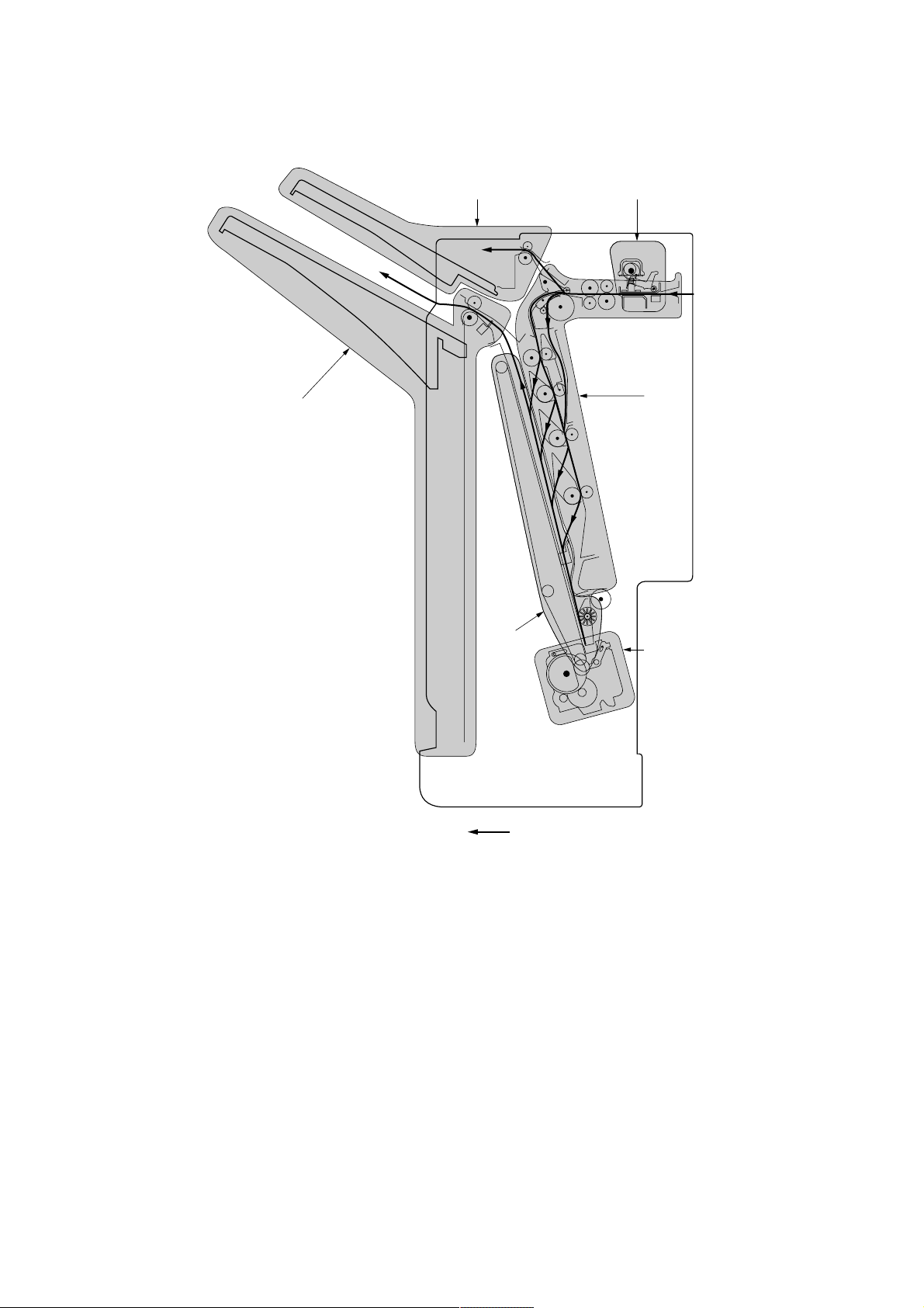
1-1-3 Machine cross section
3C1
6
5
3
1
2
4
Paper path
Figure 1-1-2 Cross section
1 Paper conveying section
2 Internal tray section
3 Punch section
4 Stapler section
5 Non-sort tray section
6 Sort tray section
1-1-3
Page 12
3C1
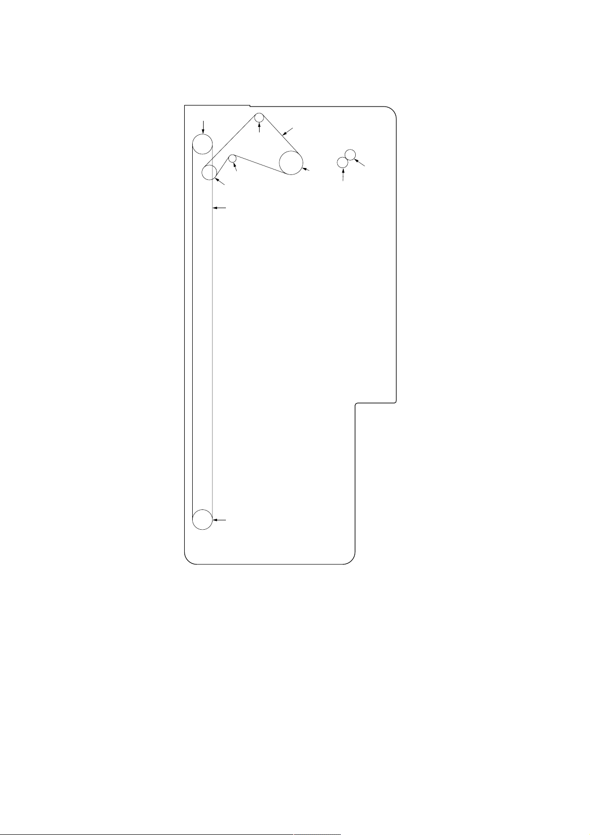
1-2-4 Drive system
7
1
5
4
6
3
2
0
9
1-1-4
8
As viewed from machine front
Figure 1-2-3 Drive system 1 (machine front)
1 Eject drive belt
2 Paper entry pulley 40
3 Tension pulley
4 Sort eject pulley 27
5 Eject pulley 20
6 Tray elevation belt
7 Pulley 20S5M
8 Pulley 20S5M
9 Gear 20
0 Gear 20
Page 13
3C1
(
)
^
&
%
$
∏
#
@
⁄
!
Í
Ï
Ó
ν
Ú
Ò
Ô
ı
˜
¯
Â
¿
˘
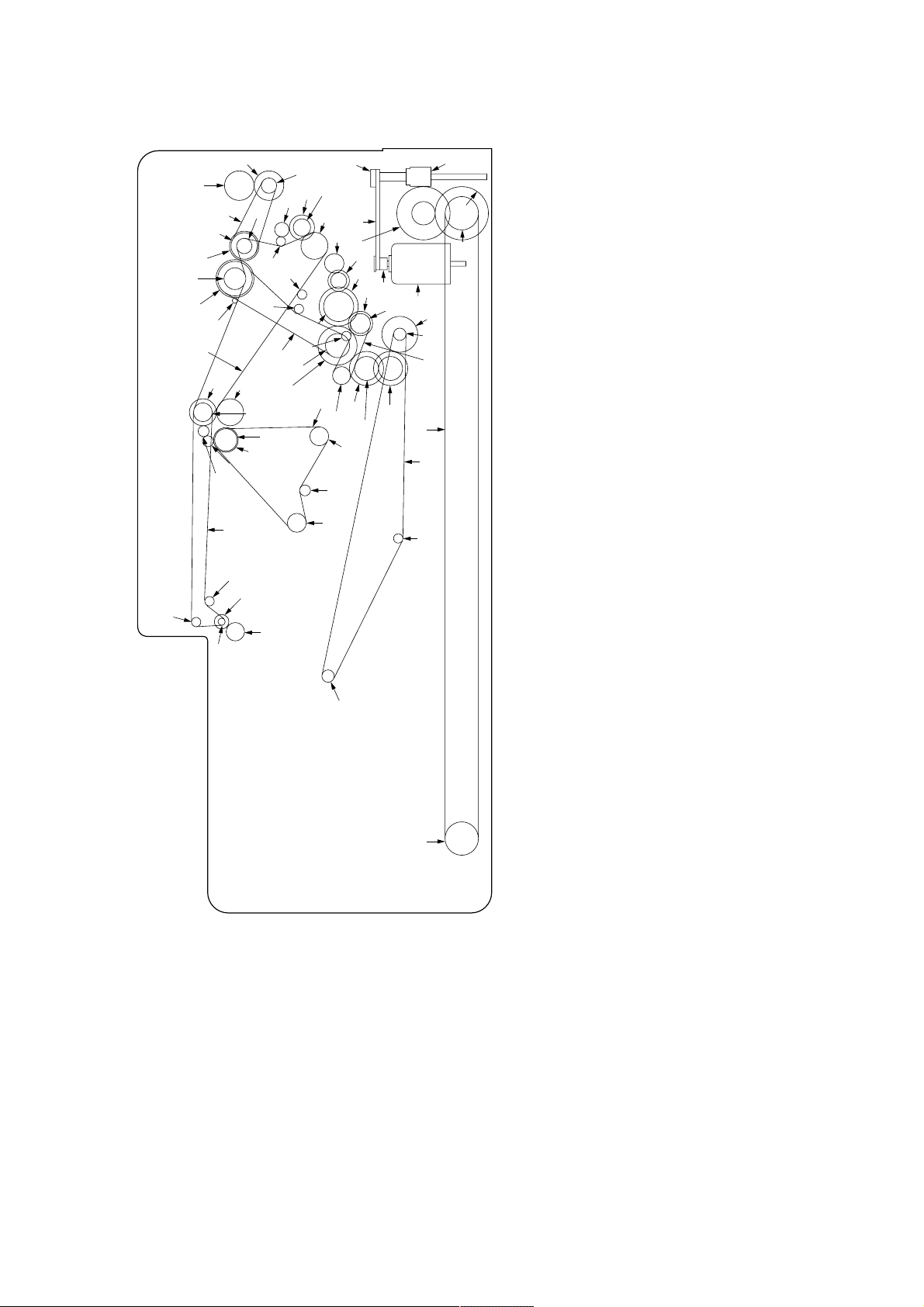
Figure 1-2-4 Drive system 2 (machine rear)
1 Tray elevation motor
2 Tray elevation motor pulley
3 Tray drive belt 22
4 Pulley 34
5 Worm gear
6 Gear 18/50
7 Gear 51
¤
∞
§
Å
£
4
3
6
*
¢
™
∏
fl
‡
2
¡
·
‹
›fi
¸
„
Œ
´
˛
Ç
◊
Ø
As viewed from machine rear
8 Pulley 20S5M
9 Tray elevation belt
0 Pulley 20S5M
! Paper conveying motor gear
@ Pulley 37/48
# Tension pulley 20
$ Gear 45
°
‰
1
9
0
¨
ˆ
ˇ
Á
‚
5
7
8
% Pulley 40
^ Pulley 30
& Punch drive belt
* Pulley 14
( Gear 29
) Punch clutch gear
⁄ Tension pulley
¤ Middle drive belt
‹ Pulley 21
› Gear 40
fi Feedshift drive gear 31
fl Paddle input gear 42
‡ Feedshift roller gear 17
— Coupling pulley 20
· Tension pulley
‚ Upper feedshift belt
ΠCoupling pulley 20
„ Gear 33
´ Gear 24SB
‰ Gear 24/33
ˇ Paper conveying belt clutch gear
Á Pulley 20S3M
¨ Paper conveying belt
ˆ Tension pulley 20S3M
Ø Middle tray idle pulley 22
” Tension pulley
Å Pulley 31
Í Feedshift drive belt
Î Coupling pulley 20
Ï Drive switching gear 27
˝ Coupling pulley 22
Ó Gear 27
Ô Sub-section interconnecting gear
Æ Sub-section interconnecting gear
Ò Feedshift gear 22
Ú Coupling pulley 20
¸ Lower feedshift belt
˛ Coupling pulley 20
Ç Tension pulley
◊ Coupling pulley 20
ı Forwarding drive belt
˜ Tension pulley
 Shutter pulley
¯ Gear Z29
˘ Shutter pulley
¿ Paper conveying clutch gear
¡ Gear 23
™ Paddle idle gear 20/22
£ Clutch gear 36
¢ Gear 16
∞ Decurler gear 34
§ Decurler gear 27
1-1-5
Page 14
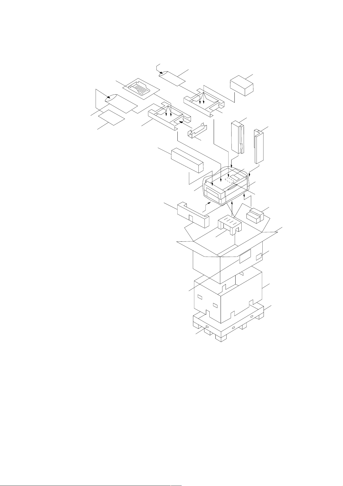
1-2-1 Unpacking
3C1
(1) Unpacking
›
‡—
2
8
$
3
#
¤
⁄
4
^)
9
fi
!
@
‹
1
&
0
5
Important: When moving the finisher, hold
the center of the sort tray mount,
otherwise the elevation belt may
become dislocated.
Figure 1-2-1 Unpacking
1 Finisher
2 Tray set assembly
3 Retainer
4 Stapler cartridges
5 Outer case
6 Inner frame
7 Bottom case
8 Upper spacer
9 Top spacer
0 Spacer (casters)
! Rear right spacer
@ Front right spacer
# Lower left spacer
$ Upper left spacer
% Middle left spacer
^ Spacer (stapler)
& Spacer (conveyor)
* Hinge joints
( Bar code labels
) Air-padded bag
%
fl
6
(
7
*
⁄ Machine cover
¤ Air-padded bag
‹ Leaflet
› Plastic bag
fi Curl eliminator set
fl Code labels
‡ Installation guide
— Installation guide
1-2-1
Page 15
3C1
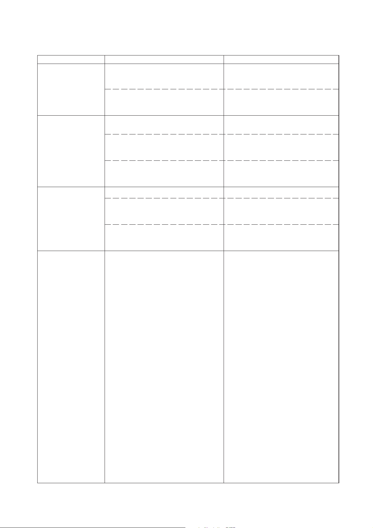
(2) Removing tapes and metal fittings
When installing the machine, be sure to remove the following tapes and metal fittings.
Procedure
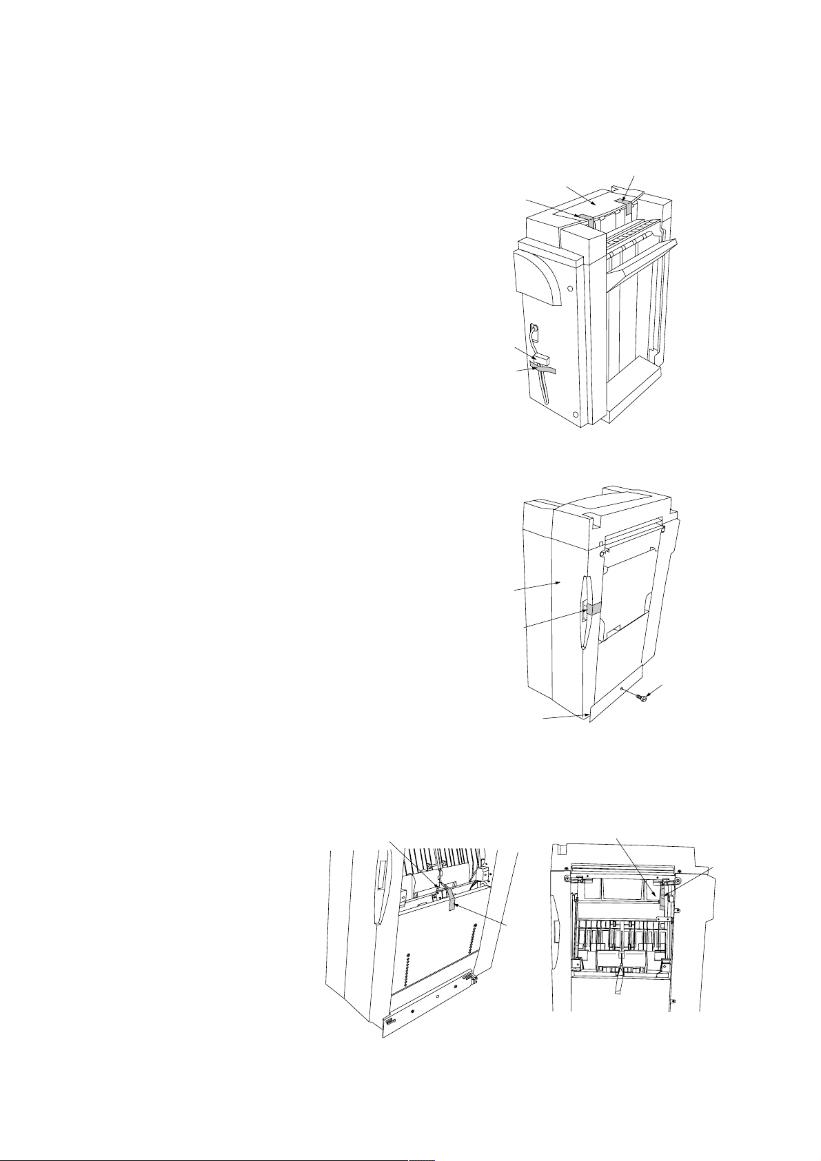
1. Remove the two tapes holding the upper cover.
2. Remove the tape holding the signal cable.
3. Remove the tape holding the front cover.
4. Remove the pin holding the rail unit.
Tape
Signal cable
Tape
Upper cover
Figure 1-2-2
Tape
5. Remove the scrap hole-punch tank and then the
tapes holding the rotating plate solenoid and the
retaining path guide.
Rotating plate solenoid
Front cover
Tape
Pin
Rail unit
Figure 1-2-3
Retaining path guide
Tape
Tape
1-2-2
Figure 1-2-4
Page 16
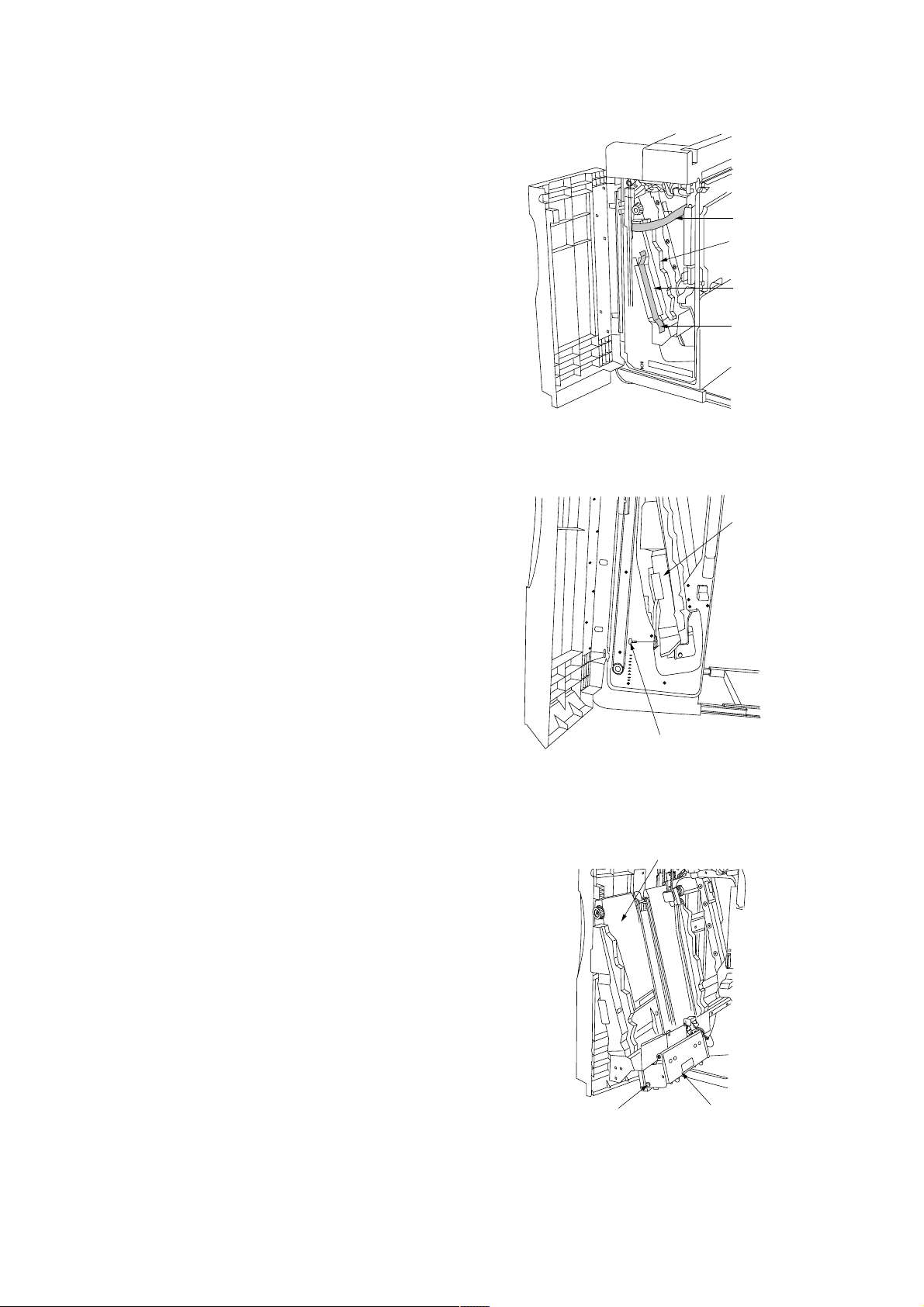
6. Open the front cover and remove the tape
holding the internal tray.
7. Remove the tape and cushion sheet
8. Remove the tape and then the pin holding the
internal tray.
3C1
Tape
Internal tray
Cushion sheet
Tape
Figure 1-2-5
Internal tray
9. Pull the internal tray out. Remove the tape and
then the pin holding the stapler unit.
Pin
Pin
Figure 1-2-6
Internal tray
Stapler unit
Figure 1-2-7
1-2-3
Page 17
3C1
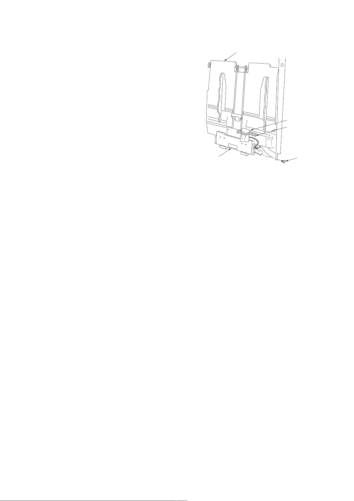
10. Remove the tape and then the cushion sheet
holding the internal tray wheel sensor.
11. Remove the tape and then the pin holding the
stapler unit.
Stapler unit
Internal tray
Cushion sheet
Tape
Pin
Figure 1-2-8
1-2-4
Page 18
1-2-2 Installing the mailbox (option)
3C1
Procedure
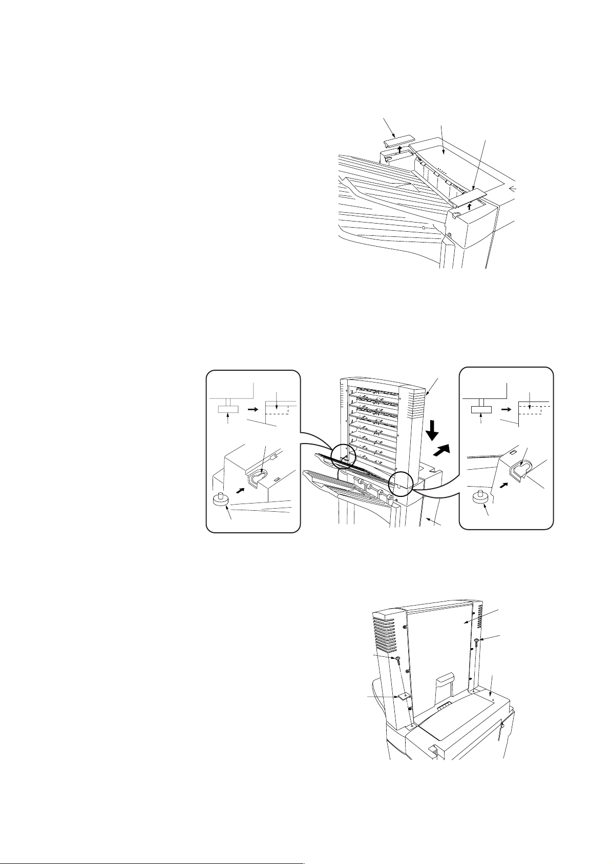
1. Remove the front top cover and rear top cover at
the top of the finisher using a flat-blade
screwdriver or the like.
2. While inserting the pins located at the front and
rear of the bottom of the mailbox into the
notches located at the front and rear of the top of
the finisher, attach the mailbox to the finisher.
Notch
Rear top cober
Finisher
Front top cover
Figure 1-2-9
Mailbox
Notch
Pin
Notch
Pin
3. Secure the front and rear attachment points of
the mailbox and finisher using a TP-A chrome
screw M4 x 14 for each.
Note: Be sure to secure the front connection
portion together with the mounting plate
cover.
Pin
Notch
Pin
Finisher
Figure 1-2-10
Mailbox
TP-A chrome
screw M4 × 14
TP-A chrome
screw M4 × 14
Finisher
Mounting
plate cover
Figure 1-2-11
1-2-5
Page 19
3C1
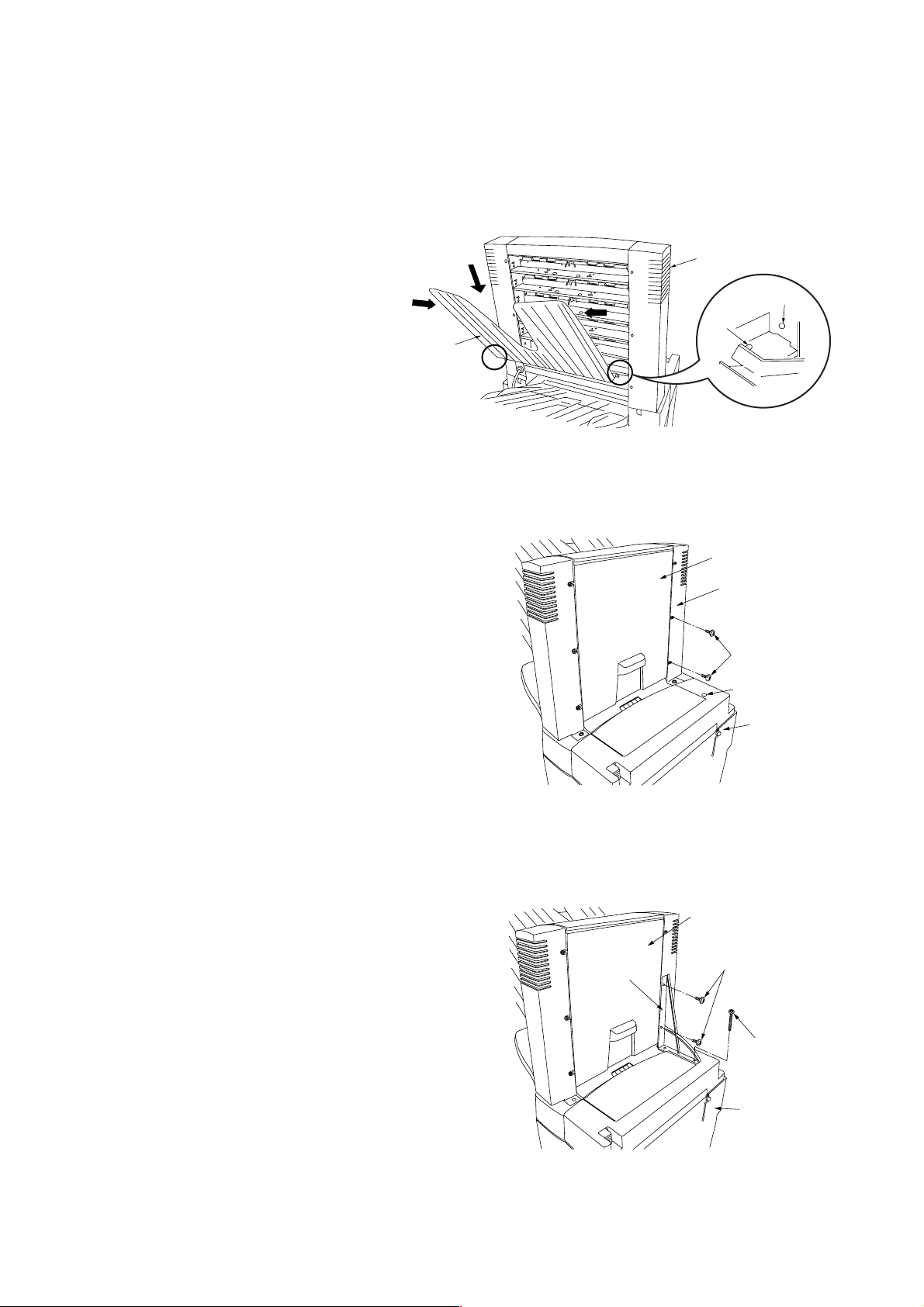
4. Fit the seven copy eject bins to the ejection
section of the mailbox from the lowest bin to the
highest.
Note: To fit a copy eject bin, hold it at an angle as
shown in the diagram, warp it lightly by
squeezing at both ends and then insert the
pins located at the front and rear into the
round holes located at the front and rear of
the mailbox.
5. Remove the two screws located as shown in the
illustration that secure the side cover of the
mailbox, and remove the blanking seal from the
finisher.
Mailbox
Round hole
Pin
Copy eject bin
Figure 1-2-12
Mailbox
Side cover
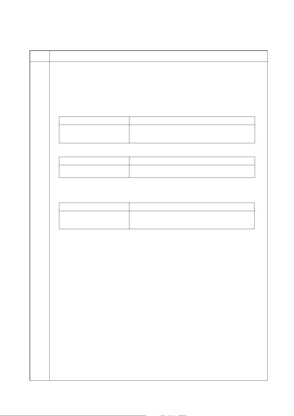
6. Attach the main body mounting plate to the
mailbox and finisher using the two TP-A chrome
screws M3 × 10 and the + bind chrome screw
M4 × 25.
Figure 1-2-13
Main body
mounting plate
Screws
Blanking seal
Finisher
Mailbox
TP-A chrome
screws M3 × 10
+Bind chrome
screw M4 × 25
1-2-6
Finisher
Figure 1-2-14
Page 20

7. Connect the finisher to the copier and connect
the signal lines of the mailbox to the connector at
the rear part of the copier.
8. Only for 230V specifications
Insert the clamp, GNK-5N and shield to near the
base of the signal line of the mailbox.
Remove the screw fitted to the copier, and
secure the clamp, GNK-5N and shield to the
copier using the screw.
9. Insert the copier power plug to the outlet and
turn the copier main switch on to check the
operation.
Signal line
Screw
3C1
Clamp
Figure 1-2-15
1-2-7
Page 21
1-3-1 Maintenance mode
3C1
Maintenance
item No.
U237 Setting finisher stack quantity
Description
Sets the number of sheets of each stack on the main tray and on the intermediate tray in the optional
finisher.
Purpose
To change the setting when a stack malfunction has occurred.
Method
1. Press the start key. The screen for selecting an item is displayed.
2. Select the item to be set. The selected item is displayed in reverse.
Display Description
MAIN TRAY Number of sheets of stack on the main tray
MIDDLE TRAY Number of sheets of stack on the intermediate tray for sort
Setting the number of sheets of stack on the main tray
1. Change the setting using the cursor up/down keys.
Setting Description
0 1500 sheets
1 3000 sheets
Initial setting: 0
2. Press the start key. The setting is set.
Setting the number of sheets of stack on the intermediate tray for sort copying or staple copying
1. Change the setting using the cursor up/down keys.
Setting Description
0 For sort copying: 30 sheets, for staple copying: 50 sheets
1 For sort copying: 50 sheets, for staple copying: 50 sheets
2 For sort copying: 30 sheets, for staple copying: 30 sheets
Initial setting: 0
2. Press the start key. The setting is set.
Completion
Press the stop/clear key. The screen for selectiong a maintenance item No. is displayed.
Description
copying or staple copying
1-3-1
Page 22
3C1
Maintenance
item No.
U240 Checking the operation of the Finisher
Description
Turns the finisher cluches or solenoids.
Purpose
To check the operation of the finisher cluches and solenoids.
Start
1 Press the start key. The screen for selecting an item is displayed.
2 Select an item. The screen for executing each item is displayed.
Display
CL, SOL TEST
JOGGER TEST
Method to check the operation of cluches and motors
1 Select the item to be operated. The selected item is displayed in reverse, and the motor or solenoid turns on
for 0.5 s.
Display Clutches and solenoids
HBCL
PYSL
PSL1
PSL2
PSL3
BSL1
BSL2
PCL
PNSL OFF
PNSL ON
PNCL
KYSL
Description
Checks operation of cluches and motors.
Checks jogging and stapling operations.
Paper conveying belt clutch (PCBCL)
Paper shift solenoid (PSSOL)
Paddle solenoid 1 (PDSOL1)
Paddle solenoid 2 (PDSOL2)
Paddle solenoid 3 (PDSOL3)
Feedshift solenoid 1 (FSSOL1)
Feedshift solenoid 2 (FSSOL2)
Paddle clutch (PDCL)
Paper shift solenoid (PSSOL) OFF
Paper shift solenoid (PSSOL) ON
Punch clutch (PCL)
Trailing edge press solenoid (TEPSOL)
Description
1-3-2
Display Clutches and solenoids
PCSL
DCSL
PGSL
2 To turn each clutch or solenoid on while the motor is driving, press the interrupt key before selecting the
clutch or solenoid.
The drive motor turns on, and the selected clutch or solenoid remains on until the selected item is pressed
again.
3 To stop the motor drive, press the interrupt key.
4 To return to the screen for selecting an item, press the stop/clear key after the motor stops.
Method to check the jogging and the stapling
1 Select the item to be operated.
2 To turn each clutch or solenoid on while the motor is driving, press the interrupt key before selecting the
clutch or solenoid.
Display
JOGGER
STAPLE
Completion
Press the stop/clear key. The screen for selecting a maintenance item No. is displayed.
Pressure switching solenoid (PSWSOL)
Drive switching solenoid (DSSOL)
Paper entry guide solenoid (PEGSOL)
Description
Operation of jogging
Operation of stapling
Page 23
3C1
Maintenance
item No.
U241 Checking the finisher switches
Description
Displays the status of the respective switches on the finisher.
Purpose
To check if respective switches on the finisher operate correctly.
Start
1 Press the start key.
2 Turn the respective switches on manually. The on-status of a switch is displayed in reverse.
Display
KOS
PS 3
FJHS
PS 2
DS
SS
RJHS
FSES
FSPS
RSES
RSPS
US
Swithes
Trailing edge press detection sensor (TEPDS)
Eject switch (ESW)
Front jogger home position sensor (FJHPS)
Internal tray wheel sensor (ITWS)
Front cover switch (FCSW)
Joint switch (JSW)
Rear jogger home position sensor (RJHPS)
Front stapler empty sensor (STES)
Front stapler self-priming sensor (STSPS)
Rear stapler empty sensor (STES)
Rear stapler self-priming sensor (STSPS)
Upper cover switch (UCSW)
Description
Display
FSTHS
RSTHS
FCES
RCES
SKS 1
PS 1
HBH S
SKS 2
PS 4
SKS 4
PKS
SKS 3
Completion
Press the stop/clear key when operation stops. The screen for selecting a maintenance item No. is displayed.
Swithes
Front stapler home position sensor (STHPS)
Rear stapler home position sensor (STHPS)
Front stapler cortridge sensor (STCS)
Rear stapler cartridge sensor (STCS)
Tray stock sensor A (TSSA)
Paper entry sensor (PES)
Paper conveying belt home position sensor (PCBHPS)
Tray stock sensor B (TSSB)
Tray midpoint sensor (TMS)
Tray lower limit sensor (TLLS)
Scrap hole-punch sensor (PDTS)
Tray upper limit sensor (TULS)
1-3-3
Page 24
3C1
Maintenance
item No.
Description
U330 Sets the number of copies for switching the copy eject tray in the finisher
Description
Sets the number of copies at which the copy eject tray will switch from the sub tray to the main tray.
Purpose
Selects the value according to user request.
Method
Press the start key. The screen for adjustment is displayed.
Setting
1 Use the numeric keys or Up/Down keys to adjust the preset value.
Description
Number of copies to be ejected on the sub tray
Setting range
1 to 100 (sheets)
Initial value
100
The copy eject tray is switched from the sub tray to the main tray when the number of copies ejected to the
sub tray exceeds the preset value.
2 Press the start key. The setting is set , and the screen for entering a maintenance item No. is displayed.
Completion
To exit this maintenance item without changing the current setting, press the stop/clear key. The screen for
selecting a maintenance item is displayed.
1-3-4
Page 25

3C1
1-4-1 Paper misfeed detection
(1) Paper misfeed detection
When a paper jam occurs, the machine stops operating immediately. The copier operation section shows a jam message and
the jam location.
To remove the jammed paper, detach the finisher from the copier.
To reset the paper misfeed detection, turn the joint switch (JSW) off and on.
(2) Paper misfeed detection conditions
ESW
PCS1
PES
PCS2
ITS
ITWS
Figure 1-4-1
1-4-1
Page 26

3C1
1. Initial clogging jam (jam code 00)
• When the power is turned on, the paper entry sensor (PES), paper conveying A3 sensor (PCSA3), paper conveying A4
sensor (PCSA4), eject switch (ESW) and internal tray sensor (ITS) are on.
2. Jam in paper entry section (jam code 81)
• The paper entry sensor (PES) does not turn on within 1287 ms of paper ejection from the copier.
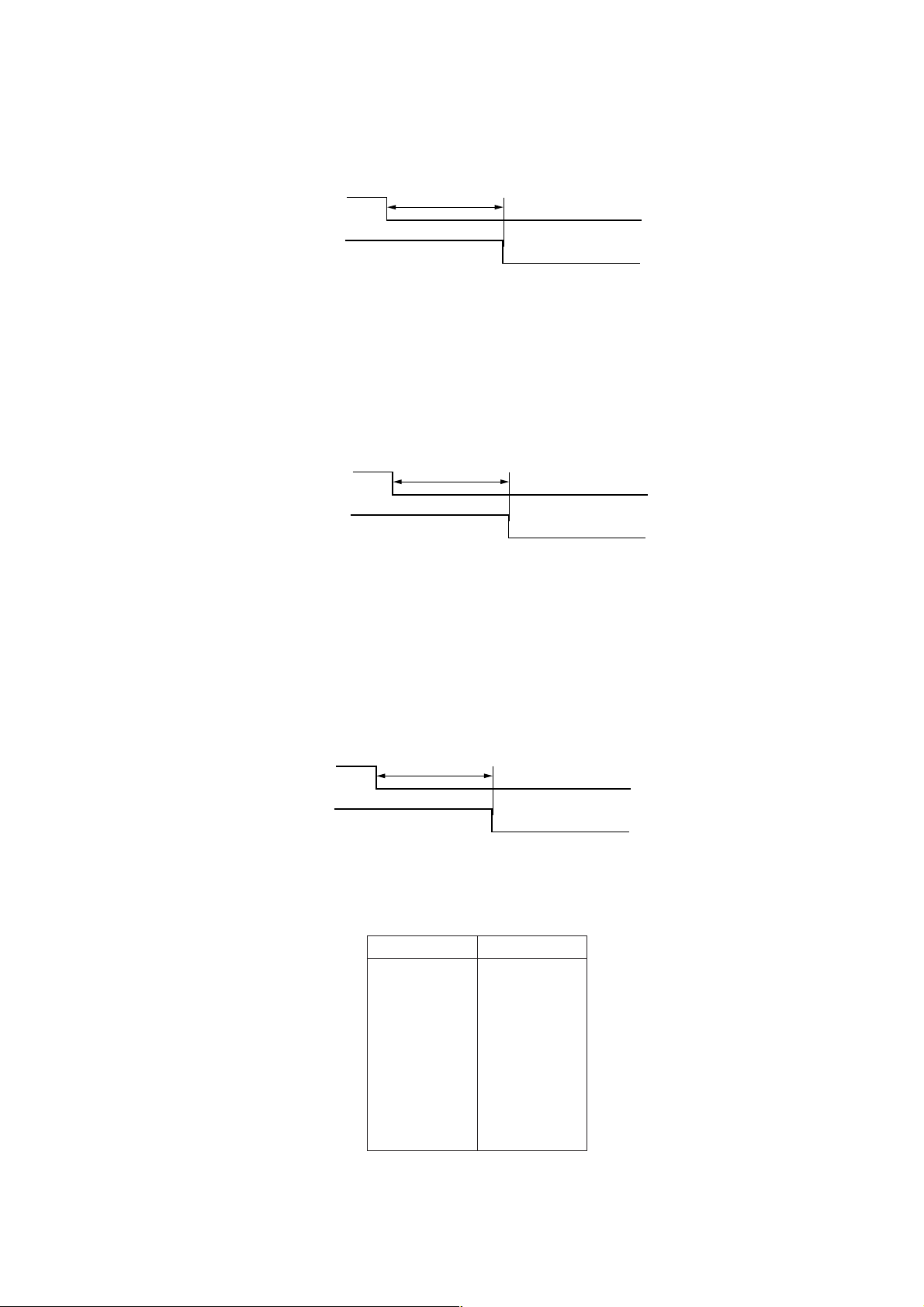
3. Jam in eject section of non-sort tray (jam code 82)
• The paper conveying sensor 1 (PCS1) does not turn on when 1424 ms elapses after the paper entry sensor (PES) has
turned on.
PES
PCS1
1424 ms
Off
On
Off
On
Timing chart 1-4-1
4. Jam in paper conveying section of internal tray (jam code 83)
• When large paper (A3, B4, A4R, ledger or legal) is fed, the internal tray wheel sensor (ITWS) does not turn on even if certain
time (depending on the paper size. See Table 1-4-1.) elapses after the paper conveying sensor 1 (PCS1) has turned on.
PCS1
ITWS
Specified time
Timing chart 1-4-2
Paper size Time (ms)
A3 1544
B4 1544
A4R 1488
Ledger 1544
Legal 1544
Table 1-4-1
Off
On
Off
On
1-4-2
Page 27
3C1
• When small paper (A4, B5 or letter) is fed, the paper conveying sensor 2 (PCS2) does not turn on even if 811 ms elapses
after the paper conveying sensor 1 (PCS1) has turned on.
PCS1
PCS2
811 ms
Off
On
Off
On
Timing chart 1-4-3
• When small paper (A4, B5 or letter) is fed, the internal tray wheel sensor (ITWS) does not turn on even if 833 ms elapses
after the paper conveying sensor 2 (PCS2) has turned on.
PCS2
ITWS
833 ms
Off
On
Off
On
Timing chart 1-4-4
5. Jam in eject section of sort tray (jam code 84)
• The eject switch (ESW) does not turn on within a specified time (varies depending on the paper size; see Table 1-4-2)
of the paper conveying belt clutch (PCBCL) turning on.
PCBCL
ESW
Specified time
Off
On
Off
On
Timing chart 1-4-5
Paper size Time (ms)
A3 500
B4 700
A4R 850
A4 1000
B5 1200
11" × 17" 500
81/2" × 14" 700
1
/2" × 11"R 850
8
1
11" × 8
/2" 1000
Table 1-4-2
1-4-3
Page 28

3C1
• The eject switch (ESW) does not turn off within a specified time (varies depending on the paper size; see Table 1-4-3)
of its turning on.
ESW
Specified time
Timing chart 1-4-6
Paper size Time (ms)
A3 1400
B4 1200
A4R 950
A4 700
B5 600
11" × 17" 1400
81/2" × 14" 1200
1
8
/2" × 11"R 950
1
11" × 8
/2" 700
Table 1-4-3
Off
On
1-4-4
Page 29

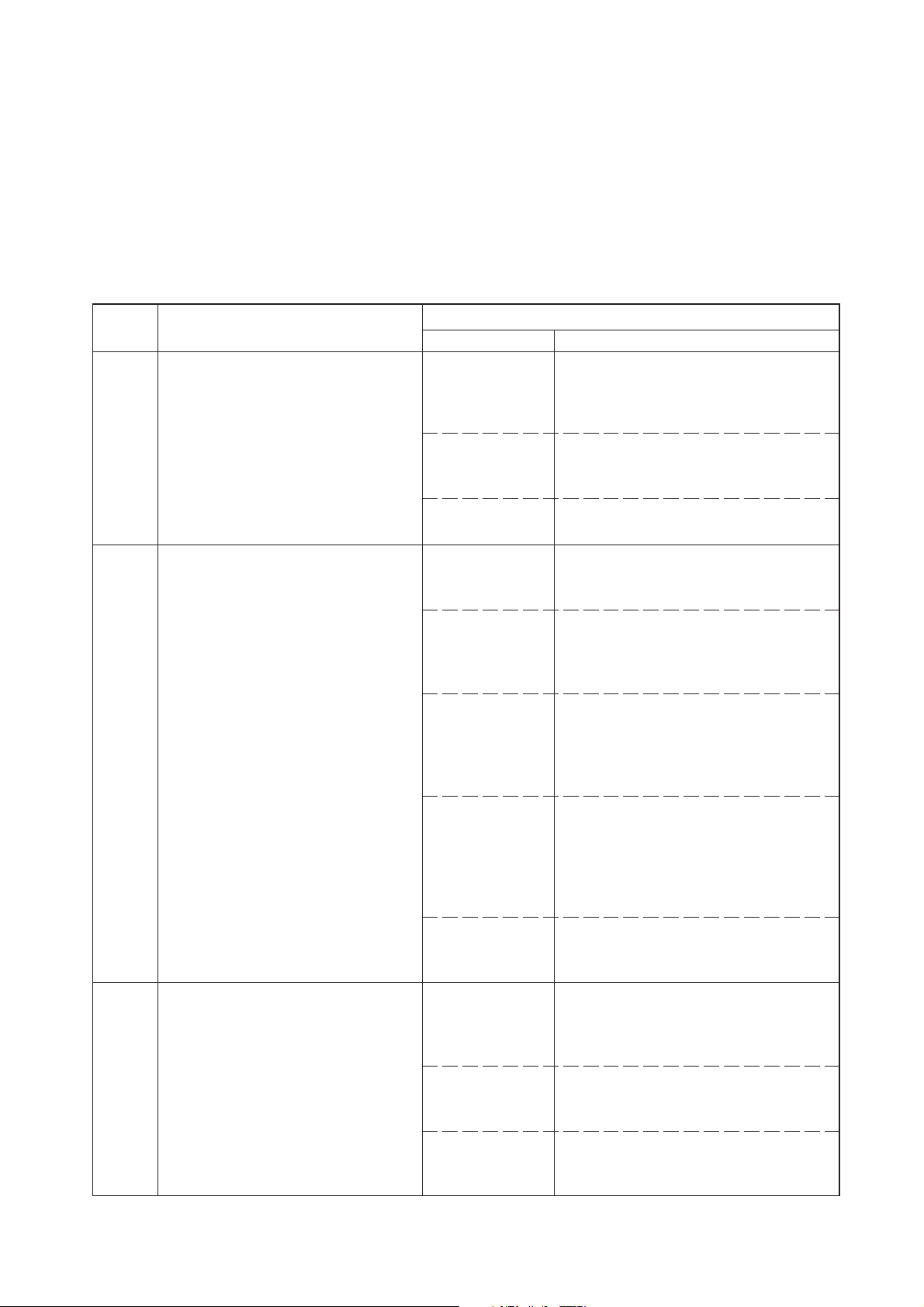
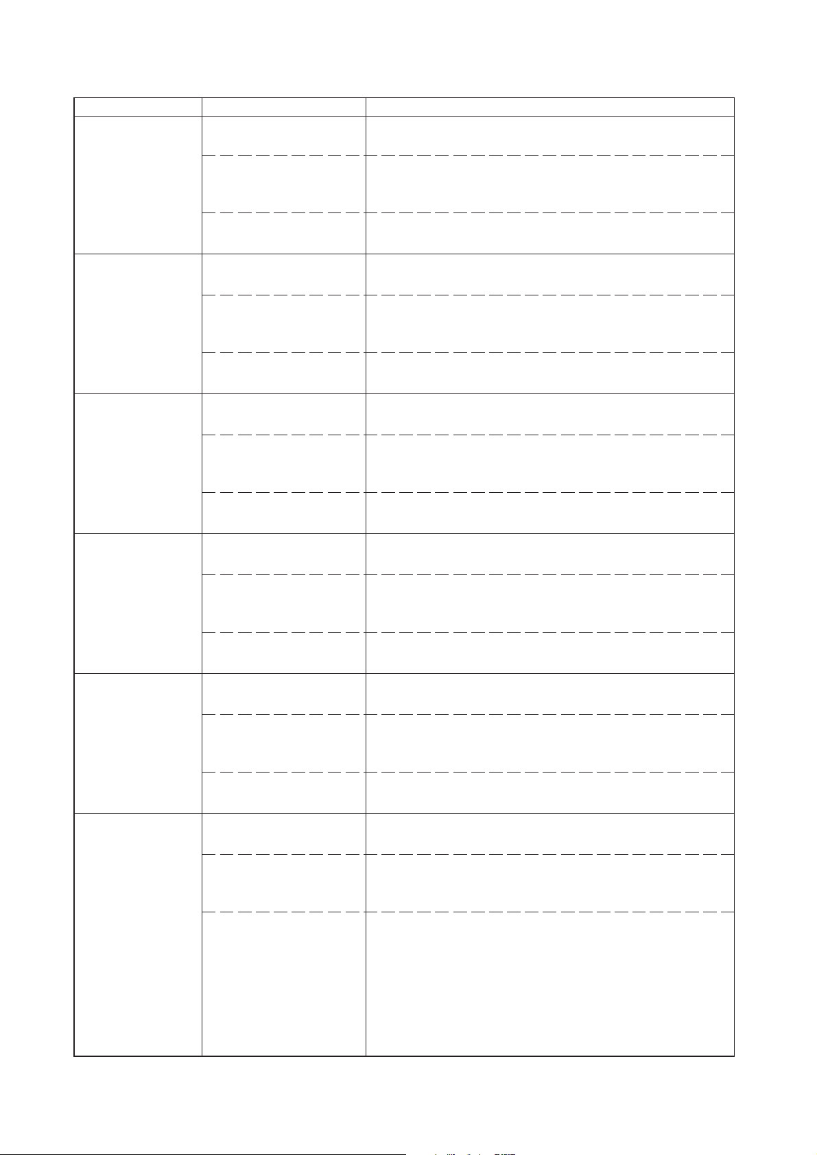
(3) Paper misfeeds
Problem Causes/check procedures Corrective measures
(1)
Paper jams when
the main switch is
turned on.
A piece of paper torn from
copy paper is caught
around the paper entry
sensor.
Check visually and remove any found.
3C1
Defective paper entry
sensor.
A piece of paper torn from
copy paper is caught
around the paper
conveying sensor 1.
Defective paper conveying
sensor 1.
A piece of paper torn from
copy paper is caught
around the paper
conveying sensor 2.
Defective paper conveying
sensor 2.
A piece of paper torn from
copy paper is caught
around the eject switch.
With 5 V DC present at CN6-1 on the main PCB, check if CN6-2
on the main PCB remains low or high when the paper entry sensor is turned on and off. If it does, replace the paper entry sensor.
Check visually and remove any found.
With 5 V DC present at CN12-16 on the main PCB, check if
CN12-14 on the main PCB remains low or high when the paper
conveying sensor 1 is turned on and off. If it does, replace the
paper conveying sensor 1.
Check visually and remove any found.
With 5 V DC present at CN12-15 on the main PCB, check if
CN12-13 on the main PCB remains low or high when the paper
conveying sensor 2 is turned on and off. If it does, replace the
paper conveying sensor 2.
Check visually and remove any found.
(2)
A paper jam is
indicated in the
paper entry section
during copying (jam
in the paper entry
section).
Defective eject switch.
A piece of paper torn from
copy paper is caught
around the internal tray
sensor.
Defective internal tray
sensor.
Extremely curled paper.
Defective paper entry
sensor.
Check if the upper or lower
paper entry guide is
deformed.
With 5 V DC present at CN6-3 on the main PCB, check if CN6-4
on the main PCB remains low or high when the eject switch is
turned on and off. If it does, replace the eject switch.
Check visually and remove any found.
With 5 V DC present at CN5-25 on the main PCB, check if
CN5-26 on the main PCB remains low or high when the internal
tray sensor is turned on and off. If it does, replace the internal
tray sensor.
Change the paper.
With 5 V DC present at CN6-1 on the main PCB, check if CN6-2
on the main PCB remains low or high when the paper entry
sensor is turned on and off. If it does, replace the paper entry
sensor.
Check and remedy.
1-4-5
Page 30

3CG
Problem Causes/check procedures Corrective measures
(3)
A paper jam is
indicated in the
paper conveying
section during
copying (jam in the
non-sort tray eject
section).
Defective paper entry sensor.
The paper conveying roller
and the upper paper conveying pulley do not make
proper contact.
With 5 V DC present at CN6-1 on the main PCB, check if CN6-2
on the main PCB remains low or high when the paper entry
sensor is turned on and off. If it does, replace the paper entry
sensor.
Check and replace if there are any problems.
(4)
A paper jam is
indicated in the
internal tray section
during copying (jam
in the internal tray
paper conveying
section).
(5)
A paper jam is
indicated in the
ejection section (jam
in the sort tray eject
section).
Check if the upper or lower
paper conveying guide is
deformed.
Defective internal tray
wheel sensor.
The feedshift rollers 1, 2, 3
and 4 and the feedshift
pulleys 1, 2, 3 and 4 do
not make proper contact.
Damaged eject switch
actuator.
Defective eject switch.
The eject roller and pulley
do not make proper
contact.
Defective paper conveying
belt.
Check and remedy.
With 5 V DC present at CN5-19 on the main PCB, check if
CN5-8 on the main PCB remains low or high when the internal
tray wheel sensor is turned on and off. If it does, replace the internal tray wheel sensor.
Replace if there are any problems.
Check and replace if there are any problems.
With 5 V DC present at CN6-3 on the main PCB, check if CN6-4
on the main PCB remains low or high when the eject switch is
turned on and off. If it does, replace the eject switch.
Check and replace if there are any problems.
Check and replace if there are any problems.
(6)
Paper jams
frequently.
The surfaces of the paper
conveying roller, or upper
and lower paper conveying
pulleys are soiled with
paper powder.
Check if the paper
conveying roller, and
upper and lower paper
conveying pulleys make
proper contact.
The surfaces of the sort
tray eject roller and pulley,
or the non-sort tray eject
roller and pulley are soiled
with paper powder.
Check if the sort tray eject
roller and pulley, and nonsort tray eject roller and
pulley make proper
contact.
Clean with isopropyl alcohol.
Remedy if necessary.
Clean with isopropyl alcohol.
Remedy if necessary.
1-4-6
Page 31
3CG
1-4-2 Self-diagnosis
(1) Self-diagnostic function
When a problem is detected in the finisher, copying is disabled and the copier operation section displays a code consisting
of “C” followed by a number between 801 and 822, indicating the nature of the problem.
After removing the problem, the self-diagnostic function can be reset by reattaching the finisher to turn the joint switch off and
on.
(2) Self diagnostic codes
Code Contents
C801
C803
Paper conveying motor problem
The paper conveying motor lockup
signal is detected for 0.5 s or longer.
Paper conveying belt problem
An on-to-off or off-to-on state change of
the paper conveying belt home position
sensor is not detected within 2 s of the
paper conveying belt clutch turning on.
Remarks
Causes Check procedures/corrective measures
The paper
conveying motor
connector makes
poor contact.
The paper
conveying motor
malfunctions.
Defective main
PCB.
The paper
conveying belt is
out of phase.
The paper
conveying belt
clutch malfunctions.
The paper
conveying belt
home position
sensor malfunctions.
Reinsert the connector. Also check for
continuity within the connector cable. If
none, remedy or replace the cable.
Replace the paper conveying motor and
check for correct operation.
Replace the main PCB and check for
correct operation.
Adjust the paper conveying belt so that it is
in phase and check for correct operation.
Replace the paper conveying belt clutch
and check for correct operation.
Replace the paper conveying belt home
position sensor and check for correct operation.
C814
Tray elevation motor problem
The sort tray is not detected in the
home position within 30 s of the start of
the tray elevation motor rotation.
When the elevation motor rises, the
tray upper limit sensor turns on for
more than 2 s.
The paper
conveying belt
home position
sensor connector
makes poor contact.
The internal tray
is incorrectly
inserted.
The tray elevation
motor connector
makes poor
contact.
The tray elevation
motor malfunctions.
Defective main
PCB.
Reinsert the connector. Also check for
continuity within the connector cable. If
none, remedy or replace the cable.
Check whether the internal tray unit or front
cover catches are damaged.
Reinsert the connector. Also check for
continuity within the connector cable. If
none, remedy or replace the cable.
Replace the tray elevation motor and
check for correct operation.
Replace the main PCB and check for
correct operation.
1-4-7
Page 32

3C1
Code Contents
C817
C818
Front jogger motor problem
While the front jogger is not detected in
the home position, the front jogger
home position sensor does not detect
the jogger within 1.5 s of the start of
front jogger motor clockwise rotation.
After the front jogger is detected in the
home position, the front jogger home
position sensor still detects the jogger
within 0.5 s of the start of front jogger
motor counterclockwise rotation.
Rear jogger motor problem
While the rear jogger is not detected in
the home position, the rear jogger
home position sensor does not detect
the jogger within 1.5 s of the start of
rear jogger motor clockwise rotation.
After the rear jogger is detected in the
home position, the rear jogger home
position sensor still detects the jogger
within 0.5 s of the start of rear jogger
motor counterclockwise rotation.
Remarks
Causes Check procedures/corrective measures
The front jogger
motor connector
makes poor
contact.
The front jogger
motor malfunctions.
The front jogger
motor home position sensor connector makes
poor contact.
The front jogger
motor home position sensor malfunctions.
Defective main
PCB.
The rear jogger
motor connector
makes poor
contact.
The rear jogger
motor malfunctions.
The rear jogger
motor home position sensor connector makes
poor contact.
Reinsert the connector. Also check for
continuity within the connector cable. If
none, remedy or replace the cable.
Replace the front jogger motor and check
for correct operation.
Reinsert the connector. Also check for
continuity within the connector cable. If
none, remedy or replace the cable.
Replace the front jogger home position
sensor and check for correct operation.
Replace the main PCB and check for
correct operation.
Reinsert the connector. Also check for
continuity within the connector cable. If
none, remedy or replace the cable.
Replace the rear jogger motor and check
for correct operation.
Reinsert the connector. Also check for
continuity within the connector cable. If
none, remedy or replace the cable.
C821
1-4-8
Front stapler problem
The front stapler home position sensor
does not change state from nondetection to detection within 0.2 s of the
start of front stapler motor
counterclockwise (forward) rotation.
During initialization, the front stapler
home position sensor does not change
state from non-detection to detection
within 0.6 s of the start of front stapler
motor clockwise (reverse) rotation.
The rear jogger
motor home position sensor malfunctions.
Defective main
PCB.
The front stapler
connector makes
poor contact.
The front stapler
malfunctions.
a) The front
stapler is blocked
with a staple.
b) The front
stapler is broken.
Defective main
PCB.
Replace the rear jogger home position sensor and check for correct operation.
Replace the main PCB and check for
correct operation.
Reinsert the connector. Also check for
continuity within the connector cable. If
none, remedy or replace the cable.
a) Remove the front stapler cartridge, and
check the cartridge and the stapling
section of the stapler.
b) Replace the front stapler and check for
correct operation.
Replace the main PCB and check for
correct operation.
Page 33

3C1
Code Contents
C822
Rear stapler problem
The rear stapler home position sensor
does not change state from nondetection to detection within 0.2 s of the
start of rear stapler motor
counterclockwise (forward) rotation.
During initialization, the rear stapler
home position sensor does not change
state from non-detection to detection
within 0.6 s of the start of rear stapler
motor clockwise (reverse) rotation.
Remarks
Causes Check procedures/corrective measures
The rear stapler
connector makes
poor contact.
The rear stapler
malfunctions.
a) The rear
stapler is blocked
with a staple.
b) The rear
stapler is broken.
Defective main
PCB.
Reinsert the connector. Also check for
continuity within the connector cable. If
none, remedy or replace the cable.
a) Remove the rear stapler cartridge, and
check the cartridge and the stapling
section of the stapler.
b) Replace the rear stapler and check for
correct operation.
Replace the main PCB and check for
correct operation.
1-4-9
Page 34

3CG
1-4-3 Electrical problems
Problem Causes Check procedures/corrective measures
(1)
The paper
conveying motor
does not operate
(C801).
Poor contact of the paper
conveying motor connector terminals.
Defective paper conveying
motor.
Reinsert the connector. Also check for continuity within the connector cable. If none, remedy or replace the cable.
Check if the paper conveying motor rotates when 24 V DC is
present at CN11-1 and 5 V DC at CN8-1, and CN8-4 is held low.
If not, replace the paper conveying motor.
(2)
The front jogger
motor does not operate (C817).
(3)
The rear jogger
motor does not operate (C818).
(4)
The tray elevation
motor does not operate (C814).
Defective main PCB.
Poor contact of the front
jogger motor connector
terminals.
Defective front jogger
motor.
Defective main PCB.
Poor contact of the rear
jogger motor connector
terminals.
Defective rear jogger
motor.
Defective main PCB.
Poor contact of the tray
elevation motor connector
terminals.
Defective tray elevation
motor.
Check if 24 V DC is present at CN11-1, 5 V DC is present at
CN8-1, and CN8-4 goes low. If not, replace the main PCB.
Reinsert the connector. Also check for continuity within the connector cable. If none, remedy or replace the cable.
Check if the front jogger motor rotates when 24 V DC is present
at CN4-5 and CN4-6, and drive pulses are at CN4-1, CN4-2,
CN4-3 and CN4-4 on the main PCB. If not, replace the front jogger motor.
Check if 24 V DC is present at CN4-5 and CN4-6 on the main
PCB. If not, replace the main PCB.
Reinsert the connector. Also check for continuity within the connector cable. If none, remedy or replace the cable.
Check if the rear jogger motor rotates when 24 V DC is present
at CN4-7 and CN4-8, and drive pulses are at CN4-9, CN4-10,
CN4-11 and CN4-12 on the main PCB. If not, replace the rear
jogger motor.
Check if 24 V DC is present at CN4-7 and CN4-8 on the main
PCB. If not replace the main PCB.
Reinsert the connector. Also check for continuity within the connector cable. If none, remedy or replace the cable.
Check if the tray elevation motor rotates when 24 V DC is
present at CN9-1 and CN9-2 on the main PCB. If not, replace
the tray elevation motor.
(5)
The front stapler
motor does not operate (C821).
1-4-10
Defective main PCB.
Poor contact of the front
stapler motor connector
terminals.
Defective front stapler
motor.
Defective main PCB.
Check if 24 V DC is present at CN9-1 and CN9-2 on the main
PCB. If not, replace the main PCB.
Reinsert the connector. Also check for continuity within the connector cable. If none, remedy or replace the cable.
Check if the front stapler motor rotates when 24 V DC is present
at CN10-1 and CN10-3 on the main PCB. If not, replace the front
stapler motor.
Check if 24 V DC is present at CN10-1 and CN10-3 on the main
PCB. If not, replace the main PCB.
Page 35

Problem Causes Check procedures/corrective measures
(6)
The rear stapler
motor does not operate (C822).
Poor contact of the rear
stapler motor connector
terminals.
Defective rear stapler
motor.
Reinsert the connector. Also check for continuity within the connector cable. If none, remedy or replace the cable.
Check if the rear stapler motor rotates when 24 V DC is present
at CN10-5 and CN10-7 on the main PCB. If not, replace the rear
stapler motor.
3C1
(7)
The paper
conveying belt
clutch does not
operate.
(8)
The paddle clutch
does not operate.
(9)
The punch clutch
does not operate.
Defective main PCB.
Broken paper conveying
belt clutch coil.
Poor contact of the paper
conveying belt clutch connector terminals.
Defective main PCB.
Broken paddle clutch coil.
Poor contact of the paddle
clutch connector terminals.
Defective main PCB.
Broken punch clutch coil.
Poor contact of the punch
clutch connector terminals.
Defective main PCB.
Check if 24 V DC is present at CN10-5 and CN10-7 on the main
PCB. If not, replace the main PCB.
Check for continuity across the coil. If none, replace the paper
conveying belt clutch.
Reinsert the connector. Also check for continuity within the connector cable. If none, remedy or replace the cable.
Check if CN5-2 on the main PCB goes low. If not, replace the
main PCB.
Check for continuity across the coil. If none, replace the paddle
clutch.
Reinsert the connector. Also check for continuity within the connector cable. If none, remedy or replace the cable.
Check if CN7-16 on the main PCB goes low. If not, replace the
main PCB.
Check for continuity across the coil. If none, replace the punch
clutch.
Reinsert the connector. Also check for continuity within the connector cable. If none, remedy or replace the cable.
Check if CN7-18 on the main PCB goes low. If not, replace the
main PCB.
(10)
The trailing edge
press solenoid does
not operate.
(11)
Feedshift solenoid 1
does not operate.
Broken trailing edge press
solenoid coil.
Poor contact of the trailing
edge press solenoid
connector terminals.
Defective main PCB.
Broken feedshift solenoid
1 coil.
Poor contact of feedshift
solenoid 1 connector terminals.
Defective main PCB.
Check for continuity across the coil. If none, replace the trailing
edge press solenoid.
Reinsert the connector. Also check for continuity within the connector cable. If none, remedy or replace the cable.
Check if CN12-9,10 on the main PCB goes low. If not, replace
the main PCB.
Check for continuity across the coil. If none, replace feedshift
solenoid 1.
Reinsert the connector. Also check for continuity within the connector cable. If none, remedy or replace the cable.
Check if CN7-2 on the main PCB goes low. If not, replace the
main PCB.
1-4-11
Page 36
3C1
Problem Causes Check procedures/corrective measures
(12)
Feedshift solenoid 2
does not operate.
Broken feedshift solenoid
2 coil.
Poor contact of feedshift
solenoid 2 connector terminals.
Check for continuity across the coil. If none, replace feedshift
solenoid 2.
Reinsert the connector. Also check for continuity within the connector cable. If none, remedy or replace the cable.
(13)
Paddle solenoid 1
does not operate.
(14)
Paddle solenoid 2
does not operate.
(15)
Paddle solenoid 3
does not operate.
Defective main PCB.
Broken paddle solenoid 1
coil.
Poor contact of paddle solenoid 1 connector terminals.
Defective main PCB.
Broken paddle solenoid 2
coil.
Poor contact of paddle
solenoid 2 connector terminals.
Defective main PCB.
Broken paddle solenoid 3
coil.
Poor contact of the paddle
solenoid 3 connector terminals.
Check if CN7-4 on the main PCB goes low. If not, replace the
main PCB.
Check for continuity across the coil. If none, replace paddle solenoid 1.
Reinsert the connector. Also check for continuity within the connector cable. If none, remedy or replace the cable.
Check if CN8-12 on the main PCB goes low. If not, replace the
main PCB.
Check for continuity across the coil. If none, replace paddle solenoid 2.
Reinsert the connector. Also check for continuity within the connector cable. If none, remedy or replace the cable.
Check if CN8-16 on the main PCB goes low. If not, replace the
main PCB.
Check for continuity across the coil. If none, replace paddle solenoid 3.
Reinsert the connector. Also check for continuity within the connector cable. If none, remedy or replace the cable.
(16)
The rotating plate
solenoid is not
activated.
(17)
The drive switching
solenoid does not
operate.
Defective main PCB.
Broken rotating plate
solenoid coil.
Poor contact of the
rotating plate solenoid
connector terminals.
Defective main PCB.
Broken drive switching solenoid coil.
Poor contact of the drive
switching solenoid
connector terminals.
Defective main PCB.
Check if CN8-20 on the main PCB goes low. If not, replace the
main PCB.
Check for continuity across the coil. If none, replace the rotating
plate solenoid.
Reinsert the connector. Also check for continuity within the connector cable. If none, remedy or replace the cable.
Check if CN12-2 on the main PCB goes low. If not, replace the
main PCB.
Check for continuity across the coil. If none, replace the drive
switching solenoid.
Reinsert the connector. Also check for continuity within the connector cable. If none, remedy or replace the cable.
Check if CN8-23 on the main PCB goes low. If not, replace the
main PCB.
1-4-12
Page 37

Problem Causes Check procedures/corrective measures
(18)
The punch pattern
solenoid does not
operate.
Broken punch pattern
solenoid coil.
Poor contact of the punch
pattern solenoid connector
terminals.
Check for continuity across the coil. If none, replace the punch
pattern solenoid.
Reinsert the connector. Also check for continuity within the connector cable. If none, remedy or replace the cable.
3C1
(19)
The pressure
switching solenoid
does not operate.
(20)
Forwarding solenoid
does not operate.
(21)
Paper jams when
the main switch is
turned on.
Defective main PCB.
Broken pressure switching
solenoid coil.
Poor contact of the pressure switching solenoid
connector terminals.
Defective main PCB.
Broken forwarding
solenoid coil.
Poor contact of the
forwarding solenoid connector terminals.
Defective main PCB.
A piece of paper torn from
copy paper is caught
around the paper entry
sensor.
Defective paper entry
sensor.
Check if CN7-8 on the main PCB goes low. If not, replace the
main PCB.
Check for continuity across the coil. If none, replace the
pressure switching solenoid.
Reinsert the connector. Also check for continuity within the connector cable. If none, remedy or replace the cable.
Check if CN7-14 on the main PCB goes low. If not, replace the
main PCB.
Check for continuity across the coil. If none, replace the
forwarding solenoid.
Reinsert the connector. Also check for continuity within the connector cable. If none, remedy or replace the cable.
Check if CN12-6 on the main PCB goes low. If not, replace the
main PCB.
Check visually and remove any found.
With 5 V DC present at CN6-1 on the main PCB, check if CN6-2
on the main PCB remains low when the paper entry sensor is
turned on and off. If it does, replace the paper entry sensor.
A piece of paper torn from
copy paper is caught
around the paper
conveying sensor 1.
Defective paper
conveyingsensor 1.
A piece of paper torn from
copy paper is caught
around the paper
conveying sensor 2.
Defective paper conveying
sensor 2.
A piece of paper torn from
the copy paper is caught
around the eject switch.
Check visually and remove any found.
With 5 V DC present at CN12-16 on the main PCB, check if
CN12-14 on the main PCB remains low when the paper
conveying sensor 1 is turned on and off. If it does, replace the
paper conveying sensor 1.
Check visually and remove any found.
With 5 V DC present at CN12-15 on the main PCB, check if
CN12-13 on the main PCB remains low when the paper
conveying sensor 2 is turned on and off. If it does, replace the
paper conveying sensor 2.
Check visually and remove any found.
1-4-13
Page 38

3C1
Problem Causes Check procedures/corrective measures
(21)
Paper jams when
the main switch is
turned on.
Defective eject switch.
A piece of paper torn from
the copy paper is caught
around the internal tray
sensor.
With 5 V DC present at CN6-3 on the main PCB, check if CN6-4
on the main PCB remains low when the eject switch is turned on
and off. If it does, replace the eject switch.
Check visually and remove any found.
(22)
“Out of staples.
(Front) Add staples.”
or “Out of staples.
(Rear) Add staples.”
is displayed when
the main switch is
turned on.
Defective internal tray
sensor.
Defective front stapler
empty sensor.
Defective front stapler cartridge sensor.
Defective rear stapler
empty sensor.
Defective rear stapler cartridge sensor.
With 5 V DC present at CN5-25 on the main PCB, check if CN526 on the main PCB remains low when the internal tray sensor
is turned on and off. If it does, replace the internal tray sensor.
With 5 V DC present at CN5-23 on the main PCB, check if CN518 on the main PCB remains low or high when the front stapler
empty sensor is turned on and off. If it does, replace the front
stapler empty sensor.
With 5 V DC present at CN5-23 on the main PCB, check if CN520 on the main PCB remains low or high when the front stapler
cartridge sensor is turned on and off. If it does, replace the front
stapler cartridge sensor.
With 5 V DC present at CN5-21 on the main PCB, check if CN510 on the main PCB remains low or high when the rear stapler
empty sensor is turned on and off. If it does, replace the rear
stapler empty sensor.
With 5 V DC present at CN5-21 on the main PCB, check if CN512 on the main PCB remains low or high when the rear stapler
cartridge sensor is turned on and off. If it does, replace the rear
stapler cartridge sensor.
1-4-14
Page 39
1-4-4 Mechanical problems
Problem Causes/check procedures Corrective measures
(1)
No paper feed.
Check if the surfaces of the paper conveying
roller, or upper and lower paper conveying
pulleys are soiled with paper powder.
3C1
Clean with isopropyl alcohol, if they are
soiled.
(2)
No paper ejection to the
sort or non-sort trays.
(3)
Paper jams.
(4)
Abnormal noise is
heard.
Check if the paper conveying roller, or upper
and lower paper conveying pulleys are deformed.
Paper outside specifications is used.
Check if the surfaces of the sort tray eject
pulley and roller, or non-sort tray eject pulley
and roller are soiled with paper powder.
Check if the sort tray eject pulley and roller,
or non-sort tray eject pulley and roller are
deformed.
Check if the paper is extremely curled.
Check if the paper conveying roller, and upper and lower paper conveying pulley make
proper contact.
Check if the sort tray eject pulley and roller,
and non-sort tray eject pulley and roller
contact each other properly.
Check if rollers, pulleys and gears all
operate smoothly.
Replace any deformed or worn pulley or
roller.
Use only paper conforming to the
specifications.
Clean with isopropyl alcohol, if they are
soiled.
Replace any deformed or worn pulleys or
rollers.
Change the paper.
Remedy if there are any problems.
Remedy if there are any problems.
Apply grease to the bushings and gears.
1-4-15
Page 40

1-5-1 Precautions for assembly and disassembly
(1) Precautions
• Be sure to turn the main switch off and disconnect the finisher power plug before starting disassembly.
• When handling PCBs, do not touch connectors with bare hands or damage the boards.
• Do not touch any PCB containing ICs with bare hands or any object prone to static charge.
1-5-2 Procedure for assembly and disassembly
(1) Detaching and refitting the static eliminator brushes
Replace the static eliminator brushes as follows.
3C1
Non-sort tray static eliminator brush
Procedure
1. Open the upper cover.
2. Remove the non-sort tray static eliminator
brush.
3. Fit a new non-sort tray static eliminator brush
so that it makes contact with the grounding
plate.
Sort tray static eliminator brush
Procedure
1. Remove the top cover (four screws).
2. Remove the sort tray static eliminator brush.
3. Fit a new sort tray static eliminator brush.
Non-sort tray static
eliminator brush
Grounding
plate
15 ± 3 mm
4 ± 1 mm
Sort tray static
eliminator brush
Upper cover
Non-sort tray static
eliminator brush
Figure 1-5-1
Non-sort tray static
eliminator brush
0 – 1 mm
8 ± 2 mm
Sort tray static eliminator brush
Figure 1-5-2
1-5-1
Page 41
3C1
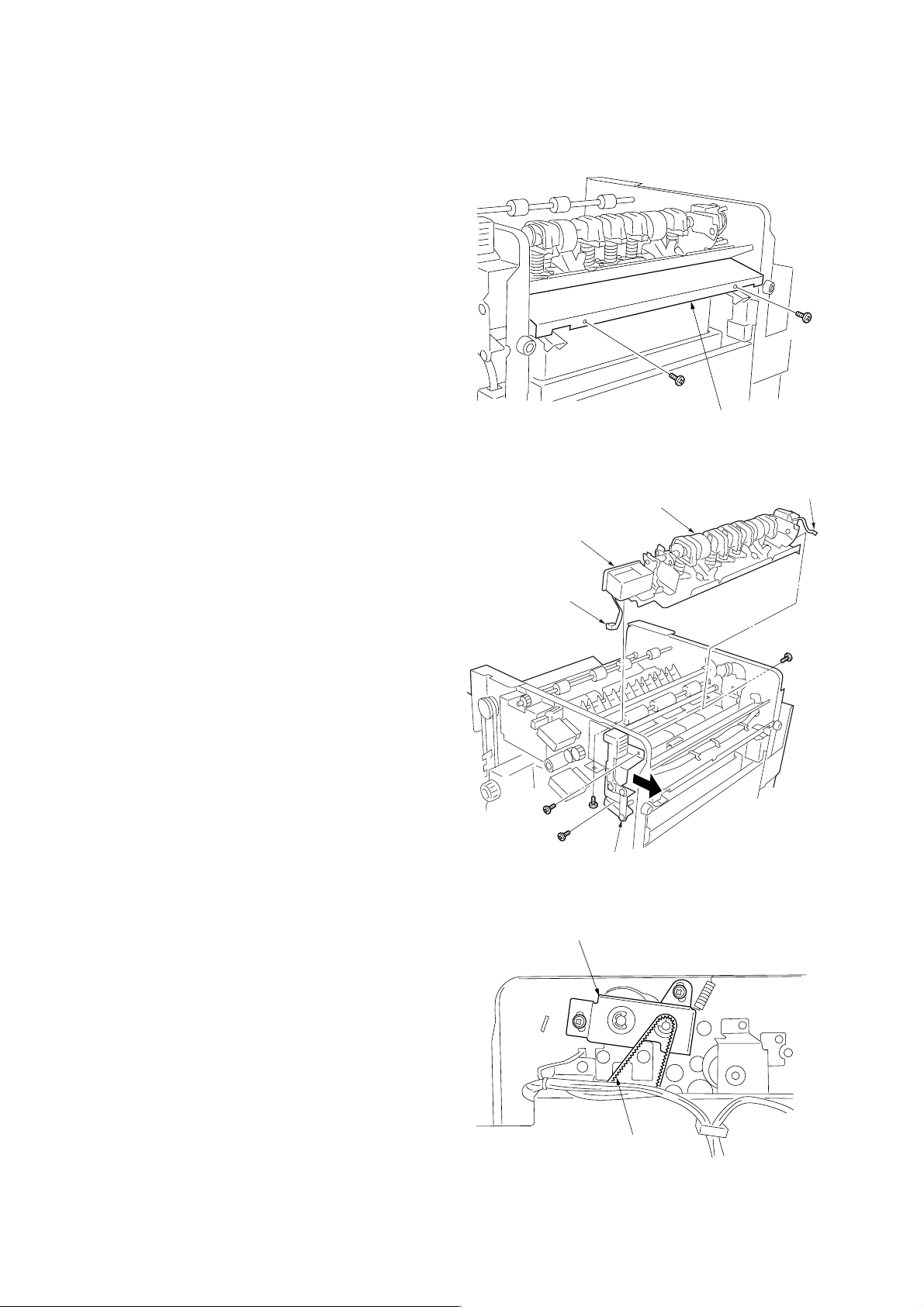
(2) Detaching and refitting the punch unit
Replace the punch unit as follows.
Procedure
1. Remove the top cover (four screws).
2. Open the front cover.
3. Remove the lower paper entry guide (two
screws).
Lower paper
entry guide
Figure 1-5-3
4. Remove the 3-pin connector of the hole-punch
pattern solenoid, and the 2-pin connector of the
punch clutch.
5. Remove the two screws holding the finisher
release button mount, and pull it in the direction
of the arrow.
6. Remove the screws holding the punch unit at
the machine front and rear (one screw each).
*At this time, turn on the punch pattern solenoid
(the axis is slid to the front side of the
machine).
7. Slide the punch unit toward the machine front
and detach it.
8. Fit a new punch unit.
*When fitting the new unit, tighten the screw at
the machine rear and then the screw at the
front.
9. Loosen the two screws of the punch drive unit,
check the tension of the tension belt, and then
tighten the screws again.
10. Refit all removed parts.
punch solenoid
3-pin connectors
Finisher release
button mount
Punch drive unit
punch unit
Figure 1-5-4
2-pin connector
1-5-2
Tension belt
Figure 1-5-5
Page 42

(3) Adjusting the center of the punch holes
Adjust the center of the punch holes after installing the finisher or when the center is displaced.
Procedure
1. Measure the distance (mm) of the punch hole
center displacement.
2. Loosen the four screws securing the retainer.
Shift the retainer by the measured distance
(mm), and tighten the screws.
• When the punch hole is displaced toward the
machine front (Figure 1-5-6), shift the retainer
Displacement
distance (mm)
toward the machine rear ( ).
• When the punch hole is displaced toward the
machine rear (Figure 1-5-7), shift the retainer
toward the machine front ( ).
Displacement
distance (mm)
3C1
Figure 1-5-6
Screws
Figure 1-5-7
Retainer
Screws
Figure 1-5-8
1-5-3
Page 43
3C1
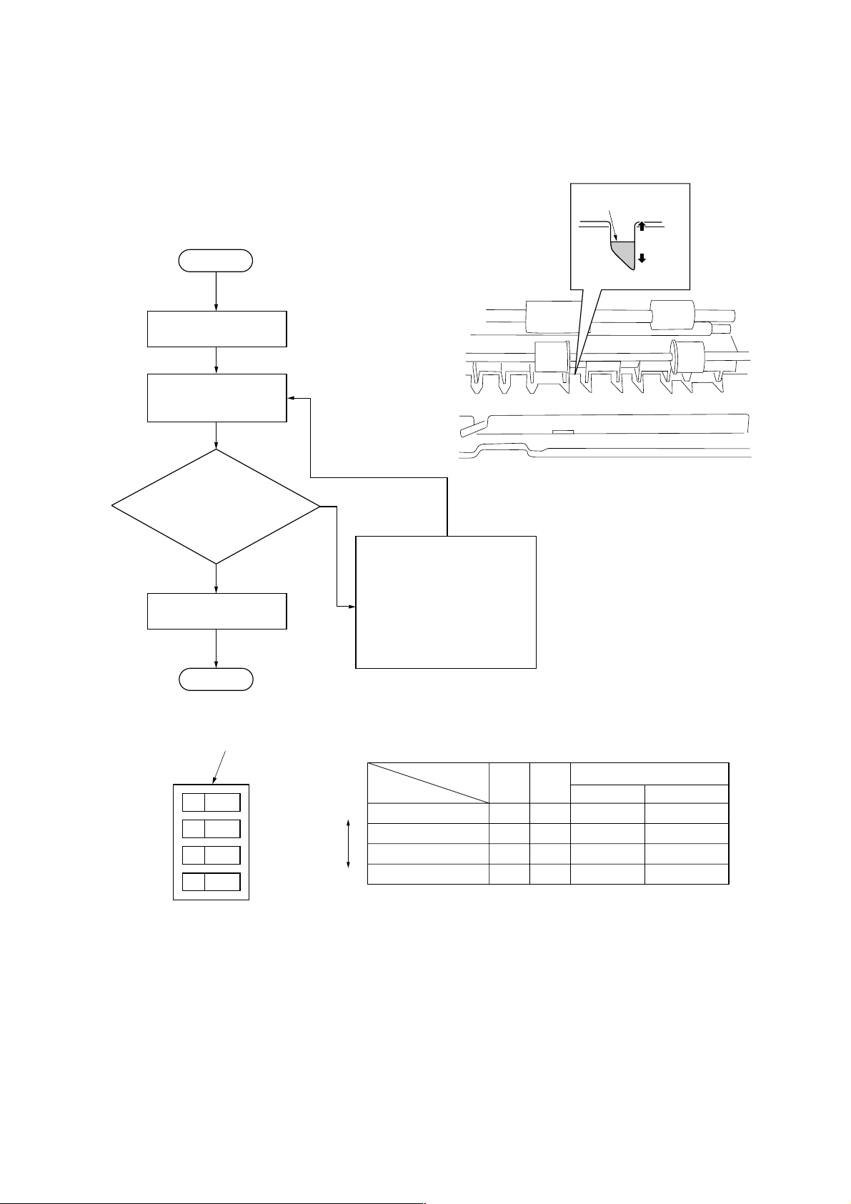
(4) Adjusting paddle clutch turn-on timing
Adjust the paddle clutch turn-on timing if, after disassembling or replacing the drive section or adjusting the belt tension, a
paper jam occurs in the paper conveying section during continuous sort copying from 2 or more originals.
Procedure
Trailing edge
of paper
Start
A
B
Remove the top and
rear covers.
Make test copies in continuous sort copy mode
using 2 or more originals.
Is the trailing
edge of the first sheet
paused in the paper conveying
section positioned within the
slots in the metal plate?
(Figure 1-5-9)
Yes
Refit the top and rear
covers.
No
Adjust the paddle clutch turn-on
timing using DIP switches 1 and
2 on the main PCB.
If the turn-on timing is set earlier,
the pausing position of the trailing
edge of the first sheet moves
toward A; if the timing is set
later, it moves toward B (Figure
1-5-9 and Figure 1-5-10).
Figure 1-5-9
End
DIP switch
ON
Figure 1-5-10
OFF
Earlier
1234
Later
Off
timing
DIP switch
A
B
C
DON
No.
12
ON ON
ON OFF
OFF OFF
OFF
Paddle clutch turn-off timing
Inch Metric
100 ms 105 ms
105 ms 110 ms
110 ms 115 ms
115 ms 120 ms
Table 1-5-1
1-5-4
Page 44

3C1
(5) Adjusting the pressure of the curl eliminator mechanism
If paper ejected from the copier is curled and a paper jam occurs, adjust the pressure of the curl eliminator mechanism to
reduce curl of paper.
Procedure
1. Remove the top cover (four screws).
2. Open the front cover.
3. Adjust the pressure of the curl eliminator using the pressure adjusting levers (five steps from 1 to 5).
*Turn the pressure adjusting levers clockwise.
• If upward curl is strong in paper ejected in the main tray (example A) or downward curl is strong in paper ejected in the
sub tray (example B):
Decrease the preset value for the upper pressure adjusting lever and increase the preset value for the lower pressure
adjusting lever.
• If downward curl is strong in paper ejected in the main tray (example B) or upward curl is strong in paper ejected in the
sub tray (example A):
Increase the preset value for the upper pressure adjusting lever and decrease the preset value for the lower pressure
adjusting lever.
Upper pressure adjusting lever
2
1
3
4
Example A Example B
Figure 1-5-11
5
5
4
3
Lower pressure adjusting lever
1
2
Figure 1-5-12
1-5-5
Page 45
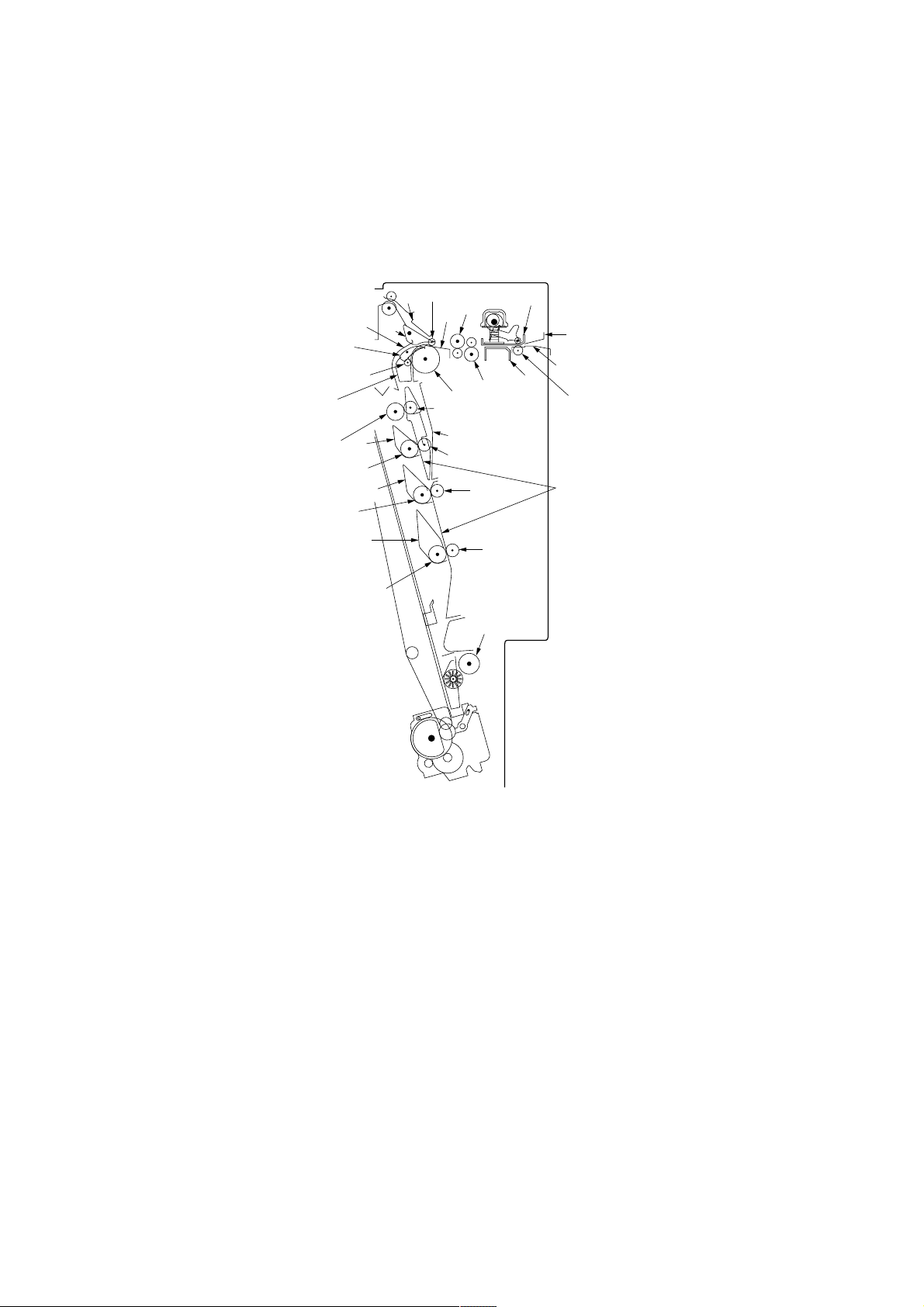
3C1
2-1-1 Construction of each section
(1) Paper conveying section
The paper conveying section consists of the components shown in Figure 2-1-1. This section conveys paper entering from
the copier to the finisher to the non-sort tray or internal tray. Feedshift claw 1 switches the paper path between the path to
the non-sort tray and the path to the internal tray.
Feedshift claw 1 is controlled by feedshift solenoid 1 (FSSOL1).
8
$
@
!
#
0
6
7
‹
9
‚
·
4
5
1
2
3
^
)
&
⁄
*
¤
(
Figure 2-1-1 Paper conveying section
1 Upper paper entry guide
2 Lower paper entry guide
3 Paper entry roller
4 Upper punch guide
5 Lower punch guide
6 Upper paper conveying guide
7 Lower paper conveying guide
8 Upper paper conveying pulley
9 Paper conveying roller
0 Feedshift claw 1
! Left paper conveyingguide
@ Feedshift claw 2
# Lower paper conveyingpulley
$ Paper conveying guide
% Retaining path guide
%
›
fi
—
fl
‡
^ Feedshift roller 1
& Feedshift roller 2
* Feedshift roller 3
( Feedshift roller 4
) Feedshift guide 1
⁄ Feedshift guide 2
¤ Feedshift guide 3
‹ Feedshift pulley 1
› Feedshift pulley 2
fi Feedshift pulley 3
fl Feedshift pulley 4
‡ Forwarding roller
— Feedshift guide
· Right curl eliminator roller
‚ Left curl eliminator roller
2-1-1
Page 46
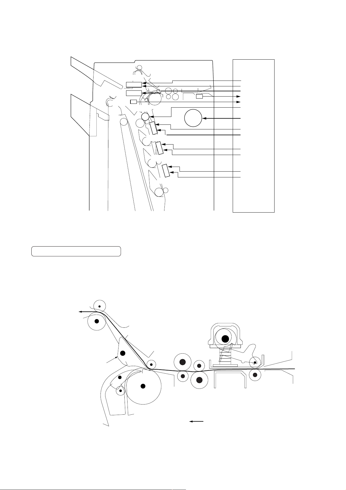
3C1
MPCB
FSSOL1
FSSOL2
PCS1
PDCL
PDSOL1
PDSOL2
PDSOL3
PES
PCM
Figure 2-1-2 Paper conveying section block diagram
CN7-20
CN7-2
CN7-4
CN6-2
CN12-14
CN7-16
CN8-4
CN8-10
CN8-12
CN8-14
CN8-16
CN8-18
CN8-20
Conveying paper to non-sort tray
In the non-sort mode, paper is conveyed through the paper conveying roller and non-sort tray eject roller to the non-sort
tray. However, paper is conveyed to the internal tray when the stapler is used or when originals are fed from the SRDF and
the punch is used.
Also a curl eliminator mechanism is provided in the transfer route to eliminate curl of paper.
To non-sort tray
Feedshift claw 1
Curl eliminator
mechanism
2-1-2
Paper path
Figure 2-1-3 Conveying paper to non-sort tray
Page 47
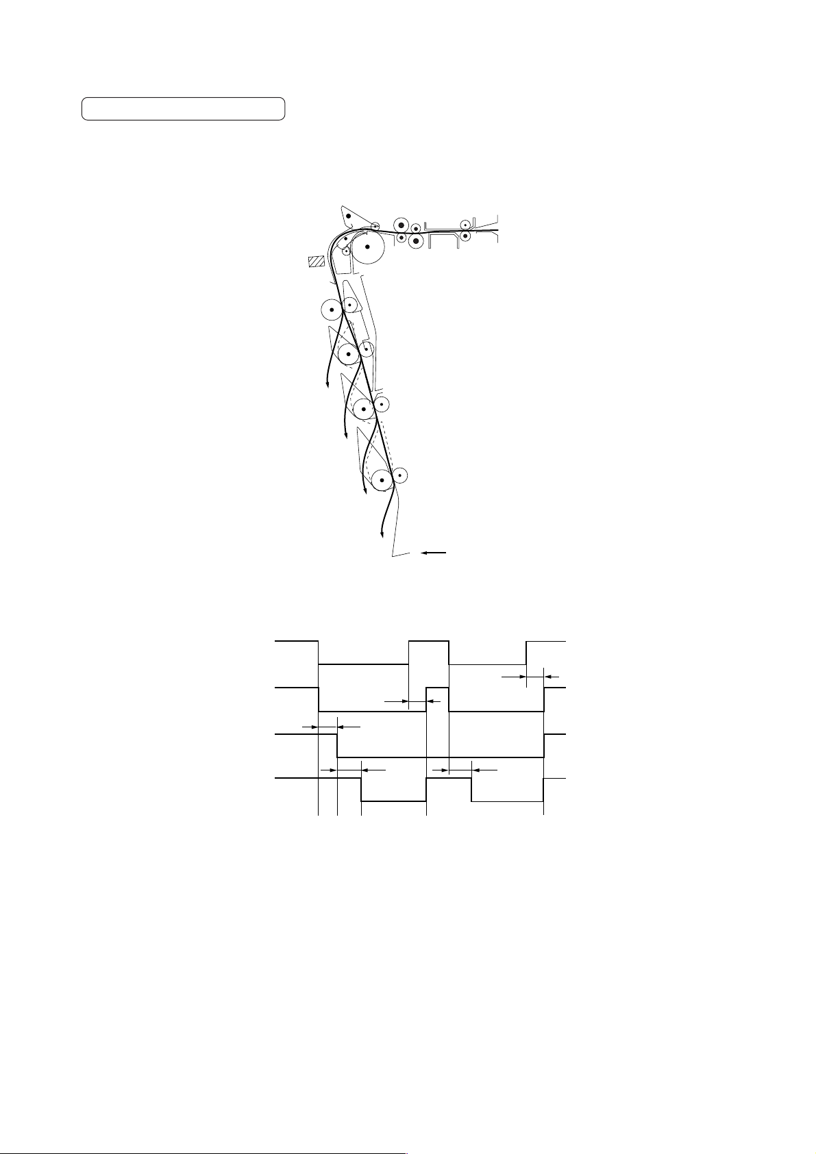
3C1
Conveying paper to internal tray
When conveying paper to the internal tray, feedshift guides 1, 2 or 3 are used according to the paper length. This is to
prevent paper misfeeding that would lead to a deviation in paper order.
Separation guides 1, 2 and 3 are controlled by paddle solenoids 1, 2 and 3 (PDSOL 1, 2, 3) respectively.
PCS1
A3/11" × 17"
B4/11" × 14"
1
A4R/8
/2" × 11"
A4/11" × 8
1
/2"
Paper path
Figure 2-1-4 Paper conveying by feedshift guides
PCSA3
PDSOL1
PDSOL2
PDSOL3
126 ms
140 ms
280 ms
ab c d e
Timing chart 2-1-1 Paper conveying operation
126 ms
280 ms
a: When the leading edge of paper passes across the paper conveying sensor 1 (PCS1), the paper conveying sensor 1
(PCS1) turns on and the paddle solenoid 1 (PDSOL1) also turns on.
b: 140 ms after the leading edge of paper has passed across the paper conveying sensor 1 (PCS1), the paddle solenoid 2
(PDSOL2) turns on.
c: 280 ms after the trailing edge of paper has passed across the paper conveying sensor 1 (PCS1), the paddle solenoid 3
(PDSOL3) turns on.
d: 126 ms after the paper conveying sensor 1 (PCS1) has turned off, the paddle solenoids 1 and 3 (PDSOL1 and 3) turn off.
e: 126 ms after the trailing edge of the last paper has passed and the paper conveying sensor 1 (PCS1) has turned off, the
paddle solenoids 1, 2, and 3 (PDSOL1, 2, and 3) turn off.
2-1-3
Page 48

3C1
Retaining path
When A4/11" × 8
1
/2" paper is conveyed to the internal tray in the sort mode, the retaining path is used. The first set of paper
is conveyed through the regular path to the internal tray. The first sheet of the second and later sets is conveyed through the
regular path, turns the paddle clutch (PDCL) on and stops in the path. Then the second sheet is guided to the retaining path
by feedshift claw 2, turning the paddle clutch (PDCL) off0. The first and second sheets are conveyed together to the internal
tray. The third and later sheets are conveyed through the regular path.
Feedshift claw 2 is controlled by feedshift solenoid 2 (FSSOL2).
The retaining path enables paper conveying during stapling, improving paper conveying efficiency.
First sheet of
second and later sets
Feedshift claw 2
Second sheet of
second and later sets
Paddle clutch
Regular path
Retaining path
2-1-4
Figure 2-1-5 Paper conveying through retaining path
Page 49

PES
PDCL
3C1
30 ms
300 ms
FSSOL2
PCBCL
230 ms
a b cd
Copy paper: A4/11" × 81/2", 2 sets of copies from 2 originals
Timing chart 2-1-2 Retaining path
a: 300 ms after the trailing edge of the first sheet of the second set passes the paper entry sensor (PES), the paddle clutch
(PDCL) turns on and the sheet stops in the regular path. At the same time, feedshift solenoid 2 (FSSOL2) turns on and
actuates feedshift claw 2 to guide the second sheet into the retaining path.
b: Simultaneously as the trailing edge of the second sheet of the second set passes the paper entry sensor (PES), the
paper conveying belt clutch (PCBCL) turns on and starts conveying paper in the internal tray.
c: 30 ms after the paper conveying belt clutch (PCBCL) turns off, the paddle clutch (PDCL) turns on and restarts conveying
the first sheet of the second set.
d: 230 ms after the trailing edge of the second sheet of the second set passes the paper entry sensor (PES), feedshift
solenoid 2 (FSSOL2) turns off, actuating feedshift claw 2 to guide the sheet into the regular path.
2-1-5
Page 50

3C1
(2) Internal tray section
In the sort mode, paper is aligned by the front and rear joggers while being conveyed to the internal tray. Once one set of
sheets is stored in the tray, the sheets of the odd-numbered sets are shifted toward the machine front, and those of the
even-numbered sets toward the machine rear. The paper conveying belt clutch (PCBCL) then turns on and the tractor
conveys paper to the sort tray.
1
2
1 Internal tray
2 Paper conveying belt clutch (PCBCL)
3 Paper conveying belt
4 Front cursor
5 Rear cursor
6 Tractor
7 Internal tray wheel
8 Internal tray wheel sensor
9 Paper receiver
0 Paper conveying sensor 2
3
Paper
0
45
6
8
7
RJHPS
FJM
FJHPS
PCBCL
RJM
9
Figure 2-1-6 Internal tray section
PCS2
MPCB
CN5-2
CN5-30
CN12-13
CN4-1 –
CN4-4
CN4-9 –
CN4-12
CN5-32
2-1-6
PCBHPS
CN5-28
Figure 2-1-7 Internal tray section block diagram
Page 51

3C1
Paper jogging and shifting operation
In the sort mode, the sides of paper are aligned by the front and rear joggers, while paper is stored in the internal tray.
Once one set of sheets is stored in the tray, the front and rear joggers shift the sheets and the sheets are then conveyed to
the sort tray. For odd-numbered sets, the front and rear joggers move toward the machine front, shifting the sheets toward
the machine front; for even-numbered sets, the joggers move toward the machine rear, shifting the sheets toward the
machine rear. The paper is thereby stocked by set in staggered order on the sort tray.
The front and rear jogger home positions are detected by the front and rear jogger home position sensors (FJHPS, RJHPS)
respectively.
Front jogger
Front jogger motor Rear jogger motor
Front jogger home
position sensor
Internal tray sensor
Internal tray wheel sensor
Figure 2-1-8
Rear jogger
Rear jogger home
position sensor
FJM
RJM
300 ms
ab ced
Moving inward
Timing chart 2-1-3 Paper jogging and shifting
a: The front and rear jogger motors (FJM, RJM) drive the front and rear joggers inward, aligning the sides of paper being
conveyed to the internal tray.
b: 300 ms after alignment, the front and rear joggers return to the standby positions.
c: Once one set of sheets is stocked in the internal tray, the front and rear jogger motors (FJM, RJM) drive the front and rear
joggers inward, aligning the sides of the sheets.
d: The front and rear joggers move outward and inward respectively, shifting the paper toward the machine front.
e: The rear jogger returns to the standby position.
Moving outward
2-1-7
Page 52

3C1
Paper switchback operation
Paper stored in the internal tray is conveyed to the sort tray by the tractor. Since the leading and trailing edges of paper
switch positions, the paper ejected face-up from the copier is reversed and stocked on the sort tray face down.
When passing the sensor lever, the tractor presses the lever down, turning on the paper conveying belt home position
sensor (PCBHPS) that then detects the tractor in the home position.
Paper conveying
belt clutch
Paper conveying belt
Tractor
Paper conveying belt
home position sensor
Sensor lever
PCBCL
PCBHPS
Figure 2-1-9
108 ms
88 ms
200 ms
abcd
Timing chart 2-1-4 Paper switchback operation
a: When the paper conveying belt clutch (PCBCL) turns on, the tractor moves, conveying paper to the sort tray.
b: 200 ms after the paper conveying belt clutch (PCBCL) turns off, it turns on again.
c: The tractor moves under the internal tray and passes the sensor lever, turning the paper conveying belt home position
sensor (PCBHPS) on.
d: 140 ms after the paper conveying belt home position sensor (PCBHPS) turns on, the tractor returns to the standby
position, turning the paper conveying belt clutch (PCBCL) off.
2-1-8
Page 53

3C1
(3) Punch section
The punch section consists of the components shown in Figure 2-1-10. Paper ejected from the copier is punched in this
section.
%
$
^
!
*
(
&
#
1 Punch cam
2 Paper stopper cam
3 Punch cam holder
4 Punch shaft
5 Punch stopper
6 Upper punch guide
7 Lower punch guide
8 Upper paper entry guide
9 Lower paper entry guide
0 Paper entry sensor (PES)
! Upper paper conveying guide
@ Lower paper conveying guide
1
‹
4
@
Figure 2-1-10 Punch section
¤
# Paper conveying guide
$ Left paper conveying guide
% Feedshift claw 1
^ Feedshift claw 2
& Paper conveying roller
* Upper paper conveying pulley
( Lower paper conveying pulley
) Paper entry pulley
⁄ Paper entry roller
¤ Right curl eliminator roller
‹ Left curl eliminator roller
7
2
3
0
5
)
⁄
6
8
9
PCL
PPSOL
Figure 2-1-11 Punch section block diagram
MPCB
CN7-18
CN7-6
CN7-8
2-1-9
Page 54
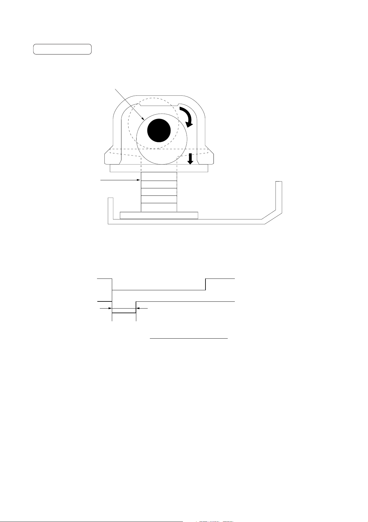
3C1
Punching operation
To punch paper, the punch cam rotates to lower the punch shaft holders.
Punch cam
Punch shaft
Figure 1-2-12 Punching operation
PES
PCL
*
ab
* Punching time = – 31 (ms)
Copier paper conveying speed
Timing chart 2-1-5 Punching operation
a: When the leading edge of paper passes the paper entry sensor (PES), the punch clutch (PCL) turns on.
The punch stopper holds the paper and the punch shafts punches the paper.
b: The punch clutch (PCL) turns off.
40.1 + 2
2-1-10
Page 55
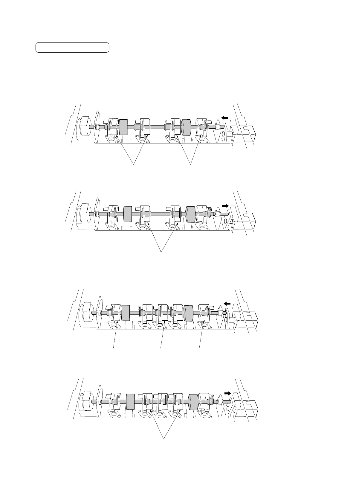
3C1
Punch pattern mechanism
The punch pattern solenoid (PPSOL) switches the punch pattern. When the solenoid turns on, the punch shaft move toward
the machine front and the number of punch cams that press the section changes.
Metric
• Four-hole punch
Punch pattern solenoid
turned off
Punch pressing
sections
• Two-hole punch
Punch pressing
sections
Inch
• Three-hole punch
Punch pressing
sections
• Two-hole punch
Punch pressing sections
Punch pressing
sections
Punch pattern solenoid
turned on
Punch pattern solenoid
turned off
Punch pressing
sections
Punch pressing sections
Figure 2-1-13 Punch pattern switching
Punch pattern solenoid
turned on
2-1-11
Page 56
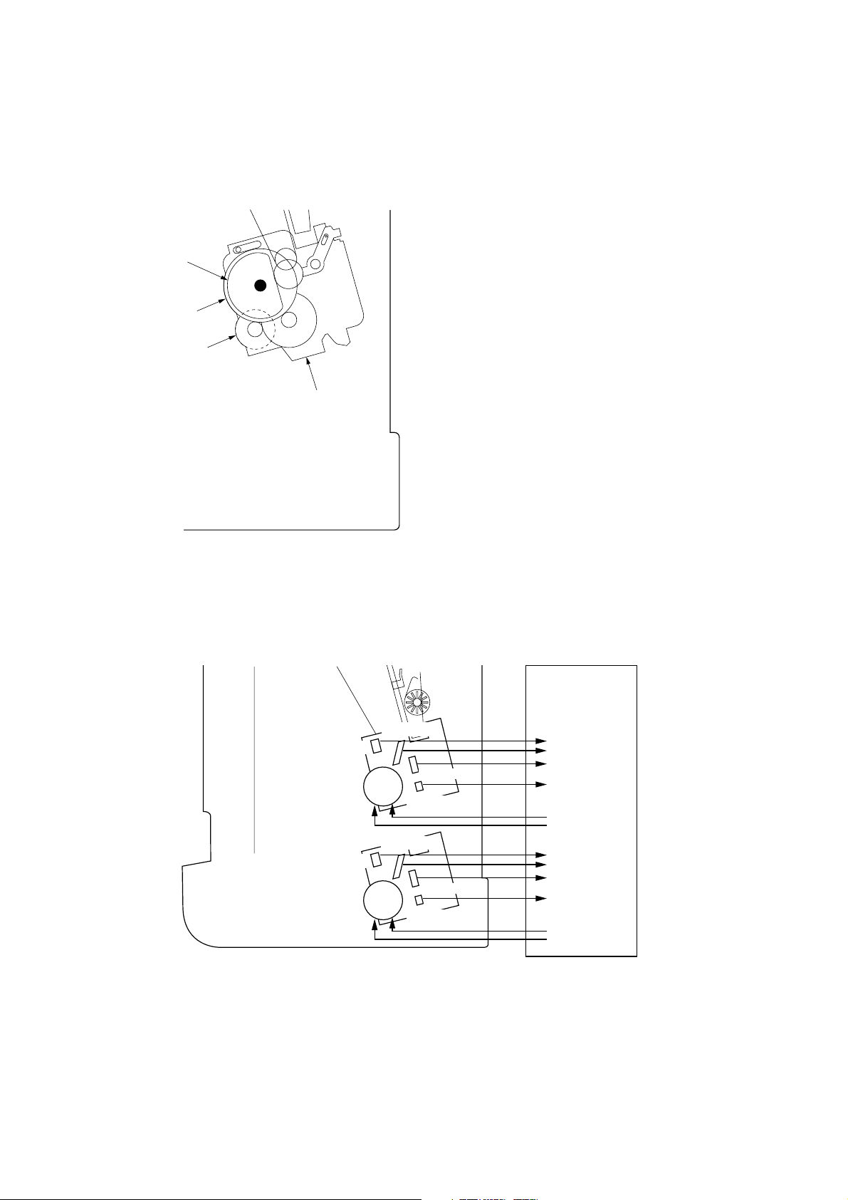
3C1
(4) Stapler section
In the staple mode, paper stored in the internal tray is stapled by the front and rear staplers. The staple modes include the
2-point stapling, front one-point stapling, rear one-point stapling modes.
The stapler motors (FSTM, RSTM) drive the front and rear staplers.
3
2
1 Stapler motor
1
Stapler unit
2 Stapler drive gear
3 Stapler cam
Figure 2-1-14 Stapler section
FSTHPS
FSTSPS
FSTCS
FSTM
FSTES
RSTHPS
RSTSPS
RSTCS
RSTM
RSTES
MPCB
CN5-22
CN5-24
CN5-20
CN5-18
CN10-1, 2
CN10-3, 4
CN5-14
CN5-16
CN5-12
CN5-10
CN10-5, 6
CN10-7, 8
2-1-12
Figure 2-1-15 Stapler section block diagram
Page 57

PES
FSTM
FSTHPS
3C1
RSTM
RSTHPS
FJM
RJM
100 ms
a bcde
Moving inward
2-point stapling, 2 sets of copies from 2 originals
Timing chart 2-1-6 Stapling operation
a: When jog operation for stapling of the one set of sheets stored in the internal tray completes, the front stapler motor
(FSTM) starts.
b: After the front stapler motor (FSTM) starts rotating, the front stapler home position sensor (FSTHPS) turns on.
c: 100 ms after the front stapler finishes stapling, the rear stapler motor (RSTM) starts rotating.
d: After the rear stapler motor (RSTM) starts rotating, the rear stapler home position sensor (RSTHPS) turns on.
e: The two-point stapling completes.
Moving outward
Stapling operation
The staplers are operated by the rotation of the stapler cams interlocked with the stapler drive gear.
Stapler
self-priming
sensor
Stapler drive gear
Stapler cam
Stapler motor
Stapler cam
Figure 2-1-16 Stapling operation
2-1-13
Page 58
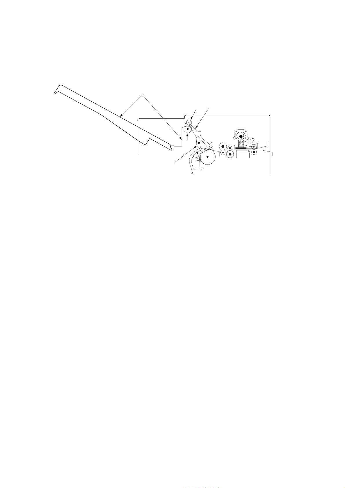
3C1
(5) Non-sort tray section
Feedshift claw 1 guides paper to the upper paper path. The paper is then ejected to the non-sort tray by the non-sort tray
eject roller and pulley.
1
34
2
5
Figure 2-1-17 Non-sort tray section
1 Non-sort tray
2 Non-sort tray eject roller
3 Non-sort tray eject pulley
4 Non-sort tray eject guide
5 Feedshift claw 1
2-1-14
Page 59
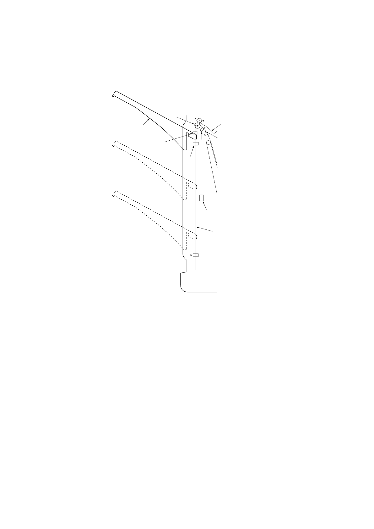
(6) Sort tray section
Sets of paper conveyed from the internal tray are ejected to the sort tray by the sort tray eject roller and pulley.
When paper on the sort tray is detected by tray stock sensors A and B (TSSA, TSSB), the sort tray descends.
The tray midpoint sensor (TMS) and tray lower limit sensor (TLLS) detect the sort tray reaching the stock limit.
3C1
1
78
!
2
9
6
0
3
@
4
5
Figure 2-1-18 Sort tray section
1 Sort tray
2 Sort tray eject roller
3 Sort tray eject pulley
4 Upper sort tray eject guide
5 Lower sort tray eject guide
6 Eject switch (ESW)
7 Tray stock sensor A (TSSA)
8 Tray stock sensor B (TSSB)
9 Tray upper limit sensor (TULS)
0 Tray midpoint sensor (TMS)
! Tray lower limit sensor (TLLS)
@ Sort tray rail
2-1-15
Page 60
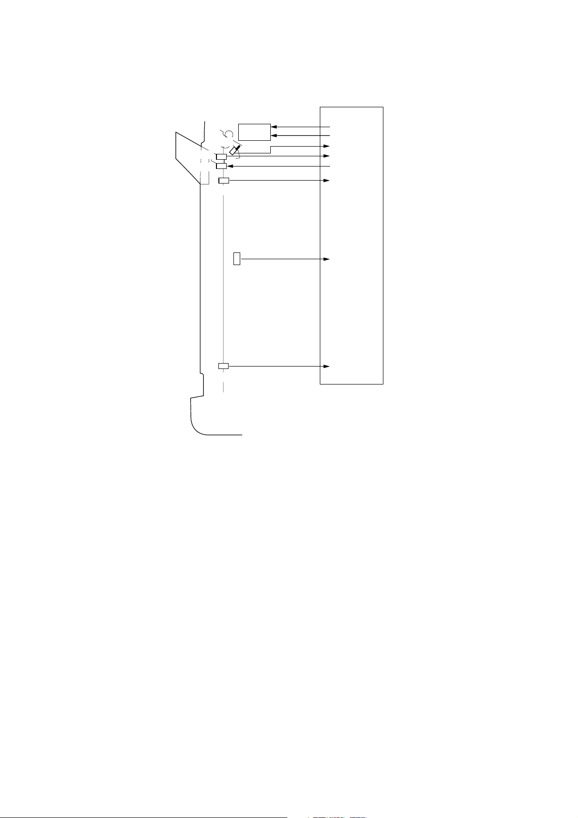
3C1
TSSA
TSSB
ESW
TULS
TMS
TEM
MPCB
CN9-1
CN9-2
CN6-4
CN6-12
CN6-14
CN6-6
CN6-8
CN6-10
TLLS
Figure 2-1-19 Sort tray section block diagram
2-1-16
Page 61

2-2-1 Electrical parts layout
3CG
1
Machine front Machine inside Machine rear
Figure 2-2-1 Electrical parts layout (PCB)
1. Main PCB (MPCB) ........................................ Controls electrical components.
2-2-1
Page 62

3CG
9,
10
12
15
17
3
18
14
1
19
5
11
4
6
7
13
Machine front Machine inside Machine rear
2
16
8
Figure 2-1-2 Electrical parts layout (switches and sensors)
1. Joint switch (JSW)......................................... Detects the finisher attached to the copier.
2. Front cover switch (FCSW) ........................... Detects opening/closing of the front cover.
3. Upper cover switch (UCSW) ......................... Detects opening/closing of the upper cover.
4. Front jogger home position sensor
(FJHPS)........................................................ Detects the front jogger in the home position.
5. Rear jogger home position sensor
(RJHPS) ....................................................... Detects the rear jogger in the home position.
6. Paper conveying belt home position sensor
(PCBHPS) ..................................................... Detects the tractor in the home position.
7. Internal tray sensor (ITS) .............................. Detects the paper entering the internal tray.
8. Internal tray wheel sensor (ITWS)................. Detects paper entering the internal tray.
9. Tray stock sensor A (TSSA).......................... Detects the presence of paper in the sort tray (receiver).
10. Tray stock sensor B (TSSB) .......................... Detects the presence of paper in the sort tray (emitter).
11. Tray midpoint sensor (TMS) .......................... Detects the sort tray reaching the lower limit while stapling or stocking
paper of other sizes than A4/11" × 8
1
/2".
12. Tray upper limit sensor (TULS) ..................... Detects the sort tray reaching the upper limit.
13. Tray lower limit sensor (TLLS) ...................... Detects the sort tray reaching the lower limit.
14. Paper entry sensor (PES) ............................. Detects paper entering the finisher.
15. Eject switch (ESW) ........................................ Detects paper exiting to the sort tray.
16. Scrap hole-punch sensor (PDTS) ................. Detects the presence of the scrap hole-punch tank.
17. Trailing edge press detection sensor
(TEPDS) ........................................................ Detects the presence of paper in the sort tray when the trailing edge
press is in contact with the paper in the sort tray.
2-2-2
Page 63

18. Paper conveying sensor 1 (PCS1) ................ Detects large paper (A3, B4, A4R, ledger or legal) that is fed to
the intermediate tray.
19. Paper conveying sensor 2 (PCS2) ................ Detects small paper (A4, B5 or letter) that is fed to the
intermediate tray.
3CG
2-2-3
Page 64

3CG
5
6
13
4
2
1
7
8
3
12
11
9
14
10
15
Machine front
Machine inside Machine rear
Figure 2-1-3 Electrical parts layout (clutches and solenoids)
1. Paper conveying belt clutch (PCBCL) ........... Drives the paper conveying belt.
2. Paddle clutch (PDCL).................................... Pauses paper passing the regular path.
3. Punch clutch (PCL) ....................................... Drives the punch.
4. Trailing edge press solenoid (TEPSOL)........ Holds the trailing edge of paper being ejected to the sort tray in non-
staple mode.
5. Feedshift solenoid 1 (FSSOL1) ..................... Switches between the sort path and non-sort path.
6. Feedshift solenoid 2 (FSSOL2) ..................... Switches the paper path to the retaining path.
7. Paddle solenoid 1 (PDSOL1) ........................ Guides A3/11" × 17" paper to the internal tray.
8. Paddle solenoid 2 (PDSOL2) ........................ Guides B4/11" × 14" paper to the internal tray.
9. Paddle solenoid 3 (PDSOL3) ........................ Guides A4R/8
1
/2" × 11" paper to the internal tray.
10. Rotating plate solenoid (RPSOL) .................. Drives the rotating plate.
11. Drive switching solenoid (DSSOL) ................ Switches the rotational direction of feedshift roller 3 and 4 to convey
A3/11" × 17" or B4/11" × 14" paper.
12. Punch pattern solenoid (PPSOL) .................. Switches the punch pattern between two-hole and three-hole (inch
specifications) or two-hole and four-hole (metric specifications).
13. Pressure switching solenoid (PSWSOL) ....... Switches paper retaining pressure while ejecting.
14. Forwarding solenoid (FWSOL) ...................... Drives the forwarding pulley.
15. Paper conveying clutch (PCCL) .................... Drives the paper conveying pulley.
2-2-4
Page 65
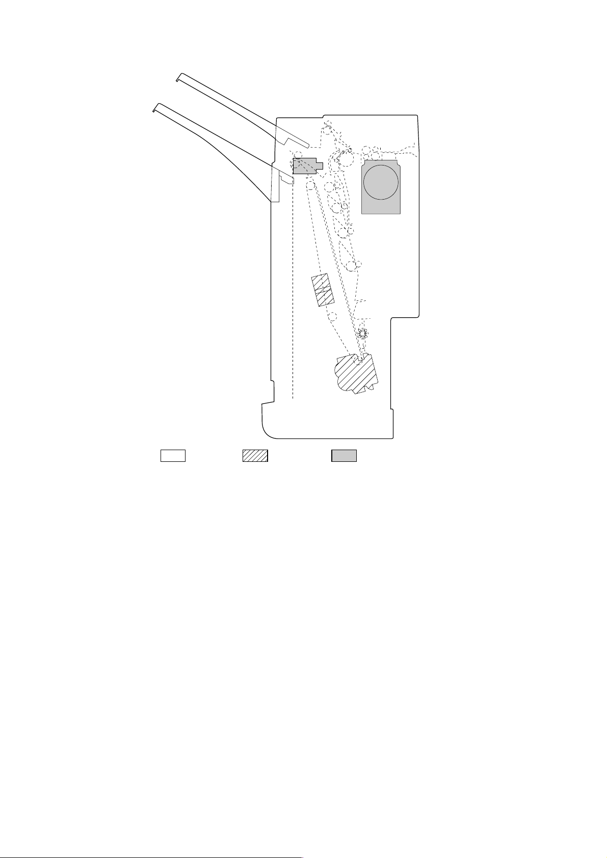
3CG
4
1
2
3
5, 6
Machine front Machine inside Machine rear
Figure 2-1-4 Electrical parts layout (motors and others)
1. Paper conveying motor (PCM) ...................... Conveys paper.
2. Front jogger motor (FJM) .............................. Aligns paper in the internal tray.
3. Rear jogger motor (RJM)............................... Aligns paper in the internal tray.
4. Tray elevation motor (TEM)........................... Raises and lowers the paper ejection tray.
5. Front stapler (FST) ........................................ Staples paper.
6. Rear stapler (RST) ........................................ Staples paper.
2-2-5
Page 66

3CG
5
1
Machine front Machine inside Machine rear
2
4
3
Figure 2-1-5 Electrical parts layout (stapler section)
1. Stapler empty sensor (STES) ....................... Detects the presence of staples.
2. Stapler cartridge sensor (STCS) ................... Detects the presence of the stapler cartridge.
3. Stapler home position sensor (STHPS) ........ Detects the stapler in the home position.
4. Stapler self-priming sensor (STSPS) ............ Detects the pre-stapling state of the stapler.
5. Stapler motor (STM)...................................... Drives the stapler.
2-2-6
Page 67

2-3-1 Main PCB
Switches,
sensors
PCM
FJM
Copier
CPU
IC8
Data bus
EPROM
IC20
Address bus
SRAM
IC18
3CG
CS
circuit
Chip
select
RJM
TEM
IC19
IC14
RSTM
ASIC
IC12
IC15
FSTM
Switches,
sensors
Clutches,
solenoids
Figure 2-3-1
The main PCB (MPCB) consists of the CPU IC8, EPROM IC20, SRAM IC18 and ASIC IC12. Following the program
written on the EPROM IC20, the main PCB controls each device and the entire operation of the finisher.
The EPROM IC20 contains a control program which is executed from the SRAM IC18. The ASIC IC12 is an extended I/O.
The copier and finisher communicate serially. Based on the communication data from the copier, the CPU IC8 on the
main PCB (MPCB) controls the entire operation of the finisher.
2-3-1
Page 68

3CG
TR3
TR5
CN3
TR6
CN4
CN1
TR2
IC3
IC8
IC13 IC14 IC17 IC18
TR4
CN11
IC15
IC21
IC9
IC2
IC19
CN2
TR1
IC25
IC6
SW1
IC22
IC24IC23
IC26
IC4
IC10
IC20
CN12
IC11
TR8
TR9
TR10
TR11
TR12
CN8
CN5
IC1
IC5
IC7
IC12
IC16
CN7
TR7
CN6
2-3-2
Figure 2-3-2
Page 69

Terminals (CN) Voltage Remarks
1-5 1-1, -2, 24 V DC 24 V DC supply, input
-3, -4
1-6 1-1, -2, 24 V DC 24 V DC supply, input
-3, -4
1-7 1-1, -2, 24 V DC 24 V DC supply, input
-3, -4
1-8 1-1, -2, 24 V DC 24 V DC supply, input
-3, -4
2-1 2-2 5 V DC 5 V DC supply, input
2-3 2-4 0/5 V DC (pulse) Serial communication signal for copier, output
2-5 2-6 0/5 V DC (pulse) Serial communication signal from copier, input
2-7 2-6 0/5 V DC RESET signal, input
2-8 2-6 0/5 V DC SET signal, input
3-1 3-3 24 V DC 24 V DC supply for JSW, output
4-1 1-1 0/5 V DC (pulse) FJM motor coil energization pulse (B)
4-2 1-1 0/5 V DC (pulse) FJM motor coil energization pulse (A_)
4-3 1-1 0/5 V DC (pulse) FJM motor coil energization pulse (B_)
4-4 1-1 0/5 V DC (pulse) FJM motor coil energization pulse (A)
4-5, -6 1-1 24 V DC 24 V DC supply for FJM, output
4-7, -8 1-1 24 V DC 24 V DC supply for RJM, output
4-9 1-1 0/5 V DC (pulse) RJM motor coil energization pulse (B_)
4-10 1-1 0/5 V DC (pulse) RJM motor coil energization pulse (A)
4-11 1-1 0/5 V DC (pulse) RJM motor coil energization pulse (B)
4-12 1-1 0/5 V DC (pulse) RJM motor coil energization pulse (A_)
5-1 5-5 24 V DC 24 V DC supply for PCBCL, output
5-2 5-5 0/24 V DC PCBCL on/off, output
5-8 5-6 0/5 V DC ITWS on/off, input
5-10 5-5 0/5 V DC RSTES on/off, input
5-12 5-5 0/5 V DC RSTCS on/off, input
5-14 5-5 0/5 V DC RSTSPS on/off, input
5-16 5-5 0/5 V DC RSTHPS on/off, input
5-18 5-5 0/5 V DC FSTES on/off, input
5-19 5-6 5 V DC 5 V DC supply for ITWS, output
5-20 5-5 0/5 V DC FSTCS on/off, input
5-21 5-5 5 V DC 5 V DC supply for RST, output
5-22 5-5 0/5 V DC FSTSPS on/off, input
5-23 5-9 5 V DC 5 V DC supply for FST, output
5-24 5-5 0/5 V DC FSTPS on/off, input
5-25 5-11 5 V DC 5 V DC supply for ITS, output
5-26 5-11 0/5 V DC ITS on/off, input
5-27 5-13 5 V DC 5 V DC supply for PCBHPS, output
5-28 5-13 0/5 V DC PCBHPS on/off, input
5-29 5-15 5 V DC 5 V DC supply for RJHPS, output
5-30 5-15 0/5 V DC RJHPS on/off, input
5-31 5-17 5 V DC 5 V DC supply for FJHPS, output
5-32 5-17 0/5 V DC FJHPS on/off, input
6-1 6-15 5 V DC 5 V DC supply for PESW, output
6-2 6-15 0/5 V DC PESW on/off, output
6-3 6-17 5 V DC 5 V DC supply for ESW, output
6-4 6-17 0/5 V DC ESW on/off, output
6-5 6-19 5 V DC 5 V DC supply for TULS, output
6-6 6-19 0/5 V DC TULS on/off, output
6-7 6-18 5 V DC 5 V DC supply for TMS, output
6-8 6-18 0/5 V DC TMS on/off, output
6-9 6-21 5 V DC 5 V DC supply for TLLS, output
6-10 6-21 0/5 V DC TLLS on/off, output
3CG
2-3-3
Page 70

3CG
Terminals (CN) Voltage Remarks
6-11 6-13 5 V DC 5 V DC supply for TEPDS, output
6-12 6-23 0/5 V DC TSSA on/off, input
6-14 6-25 0/5 V DC TSSB on/off, input
6-16 6-13 0/5 V DC TEPDS on/off, input
6-22 6-13 0/24 V DC JSW on/off, input
6-24 6-13 0/24 V DC FCSW on/off, input
6-26 6-13 0/24 V DC UCSW on/off, input
7-1 1-1 24 V DC 24 V DC supply for FSSOL1, output
7-2 1-1 0/24 V DC FSSOL1 release signal, output
7-3 1-1 24 V DC 24 V DC supply for FSSOL2, output
7-4 1-1 0/24 V DC FSSOL2 on/off, output
7-6 1-1 0/24 V DC PPSOL latch-on signal, output
7-8 1-1 0/24 V DC PPSOL release signal, output
7-13 1-1 24 V DC 24 V DC supply for PSWSOL, output
7-14 1-1 0/24 V DC PSWSOL on/off, output
7-15 1-1 24 V DC 24 V DC supply for PDCL, output
7-16 1-1 0/24 V DC PDCL on/off, output
7-17 1-1 24 V DC 24 V DC supply for PCL, output
7-18 1-1 0/24 V DC PCL on/off, output
7-20 1-1 0/24 V DC FSSOL1 latch-on signal, output
8-1 1-1 5 V DC 5 V DC supply for PCM, output
8-2 1-1 0/5 V DC PCM LOCK signal, output
8-3 1-1 0/24 V DC PCM on/off, output
8-6 1-1 0/5 V DC (pulse) PCM CLOCK signal, output
8-8 1-1 0/5 V DC PDTS on/off, input
8-10 1-1 0/24 V DC PDSOL1 latch-on signal, output
8-11 1-1 0/5 V DC 24 V DC supply for PDSOL1, output
8-12 1-1 0/24 V DC PDSOL1 release signal, output
8-13 1-1 24 V DC 24 V DC supply for PDSOL2, output
8-14 1-1 0/24 V DC PDSOL2 latch-on signal, output
8-15 1-1 24 V DC 24 V DC supply for PDSOL3, output
8-16 1-1 0/24 V DC PDSOL2 release signal, output
8-18 1-1 0/24 V DC PDSOL3 latch-on signal, output
8-19 1-1 24 V DC 24 V DC supply for DSSOL, output
8-20 1-1 0/24 V DC PDSOL3 release signal, output
8-23 1-1 0/24 V DC DSSOL latch-on signal, output
8-24 1-1 0/24 V DC DSSOL release signal, output
9-1 1-1 0/24 V DC TEM drive signal +, output
9-2 1-1 0/24 V DC TEM drive signal –, output
10-1, -2 1-1 0/24 V DC FSTM reverse/forward rotation +, output
10-3, -4 1-1 0/24 V DC FSTM forward/reverse rotation –, output
10-5, -6 1-1 0/24 V DC RSTM reverse/forward rotation +, output
10-7, -8 1-1 0/24 V DC RSTM forward/reverse rotation –, output
11-1, -2 11-3 24 V DC 24 V DC supply for PCM, output
12-1 1-1 24 V DC 24 V DC supply for RPSOL, output
12-2 1-1 0/24 V DC RPSOL on/off, output
12-3 1-1 24 V DC 24 V DC supply for PCCL, output
12-4 1-1 0/24 V DC PCCL on/off, output
12-5 1-1 24 V DC 24 V DC supply for FWSOL, output
12-6 1-1 0/24 V DC FWSOL on/off, output
12-7 1-1 24 V DC 24 V DC supply for TEPSOL, output
12-9 1-1 0/24 V DC TEPSOL latch-on signal, output
12-10 1-1 0/24 V DC TEPSOL release signal, output
12-13 12-11 0/5 V DC PCS2 on/off, input
12-14 12-12 0/5 V DC PCS1 on/off, input
12-15 12-11 5 V DC 5 V DC supply for PCS2, output
12-16 12-12 5 V DC 5 V DC supply for PCS1, output
2-3-4
Page 71
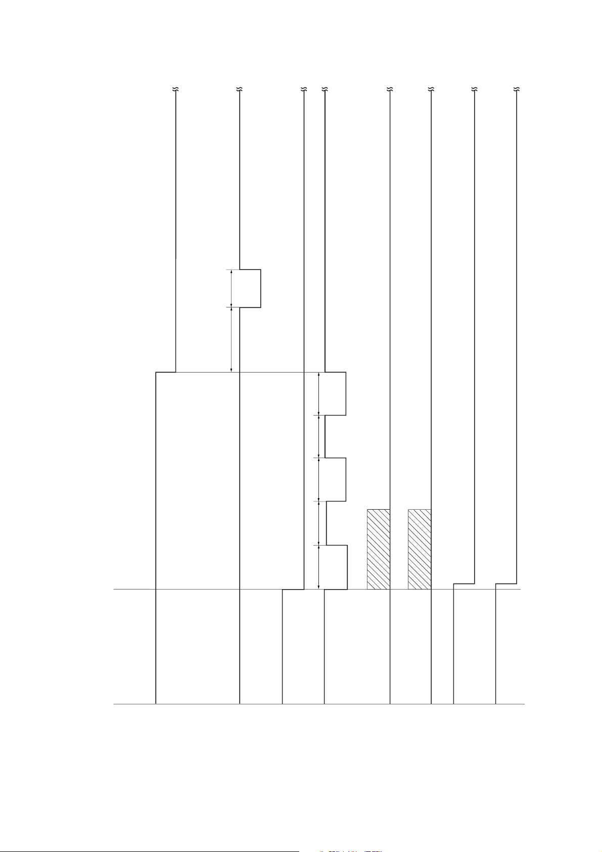
3C1
PCM CN8-4
PPSOL CN7-6
CN7-8
FSSOL1 CN7-2
CN7-20
DSSOL CN8-23
CN8-24
FJM CN4-1 –
CN4-4
RJM CN4-9 –
CN4-12
RJHPS CN5-30
FJHPS CN5-32
200 ms
500 ms 200 ms
500 ms
200 ms
500 ms
200 ms
Moving to standby position
Operation start
Moving to standby position
Timing chart No. 1 Initial operation
2-4-1
Page 72

PCM CN8-4
PES CN6-2
ESW CN6-4
PCL CN7-18
PRSOL CN12-2
PCCL CN12-4
FWSOL CN12-6
PDSOL3 CN8-18
CN8-20
PDSOL2 CN8-14
CN8-16
PCBHPS CN5-28
PCBCL CN5-2
FJM CN4-1 –
CN4-4
RJM CN4-9 –
CN4-12
TEPSOL CN12-9
CN12-10
PSWSOL CN7-14
247 ms
247 ms
300 ms
300 ms
300 ms
213 ms
88 ms
200 ms
108 ms
1st sheet
*1
2nd sheet
Jogging
Jogging
Moving to
home position
Shifting
Moving inward
Moving outward
Batch ejection start
Operation start
cleared
– 31 (ms)
40.1 + 2
Copier paper conveying speed
*1 Punching time =
PCS1 CN12-14
79 ms
200ms
79 ms
3C1
× ×
× ×
× 17" copy paper, two originals
Timing chart No. 2 Punch-sort mode: A3/11"
2-4-2
Page 73

PCM CN8-4
PES CN6-2
PCS2 CN12-13
PCCL CN12-4
ESW CN6-4
PRSOL CN12-2
PCL CN7-18
PDCL CN7-16
PCBHPS CN5-28
FWSOL CN12-6
FSTMF CN10-1
–
CN10-4
RSTMF CN10-5
–
CN10-8
PCBCL CN5-2
RSTHPS CN5-16
FSTHPS CN5-24
PCS1 CN12-14
FJM CN4-1 –
CN4-4
RJM CN4-9 –
CN-12
1st sheet 2nd sheet 3rd sheet 4th sheet
Operation start
cleared
Moving to
home position
Moving inward
Moving outward
– 31 (ms)
40.1 + 2
Copier paper conveying speed
*1 Punching time =
223 ms
305 ms
88 ms
200 ms
*1
185 ms
160 ms
54 ms
270 ms
100 ms
70 ms
100 ms
43 ms
110 ms
108 ms
3C1
" copy paper, two sets of copies from two originals, two-point stapling
2
/
1
× ×
× ×
× 8
Timing chart No. 3 Punch-sort mode: A4/11"
2-4-3
Page 74
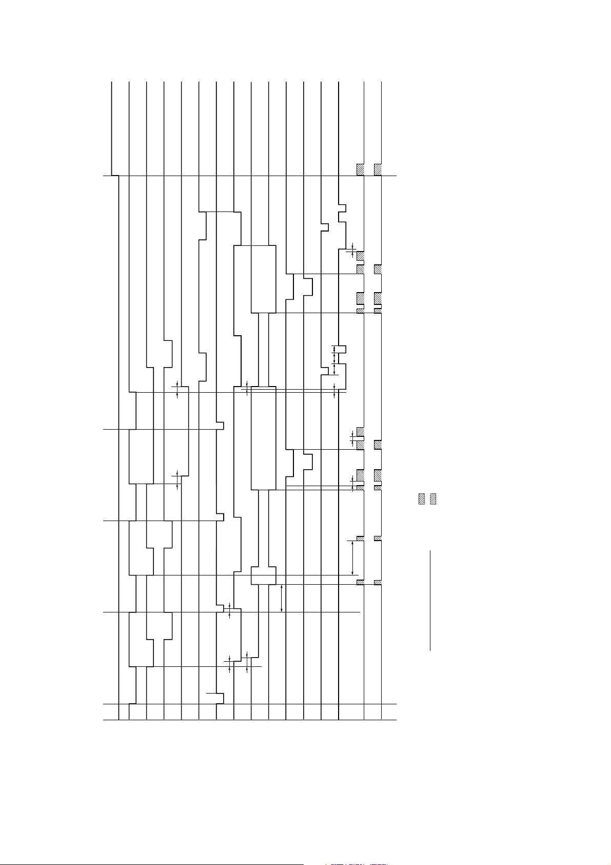
PCM CN8-4
PES CN6-2
PCS2 CN12-13
PCCL CN12-4
ESW CN6-4
PRSOL CN12-2
PCL CN7-18
PDCL CN7-16
PCBHPS CN5-28
PWSOL CN12-6
RSTMF CN10-5
–
CN10-8
PCBCL CN5-2
RSTHPS CN5-16
PCS1 CN12-14
FJM CN4-1 –
CN4-4
RJM CN4-9 –
CN-12
1st sheet 2nd sheet 3rd sheet 4th sheet
Operation start
cleared
Moving to
home position
Moving inward
Moving outward
– 31 (ms)
40.1 + 2
Copier paper conveying speed
*1 Punching time =
315 ms
305 ms
88 ms
200 ms
*1
185 ms
165 ms
54 ms
170 ms
70 ms
50 ms
100 ms
43 ms
110 ms
50 ms
108 ms
3C1
" copy paper, two sets of copies from two originals, rear one-point stapling
2
/
1
× ×
× ×
× 8
Timing chart No. 4 Punch-sort mode: A4/11"
2-4-4
Page 75

A B C D E F G H IJ
A B C D E F G H IJ
1
2
3
4
5
6
7
8
1
2
3
4
5
6
7
8
Wiring diagram
PCM
C101
CN-9:C002
1234567891011121314151617181920
12345678910
12345678910
1234567891011 12 13 14 15 16 17 18 19 20
C111 C301
GY C003-26
RD C001-3
RD C004-1
GY C004-20
GY C004-2
RD C004-1
GY C004-4
RD C004-3
BE C003-25
YW C003-14
GY C008-10
GY C008-9
RD C008-7
BE C003-13
YW C003-16
OE C003-11
YW C004-4
OE C003-2
BE C003-17
GY P001-3
GY P001-2
GY P001-1
GY C302-3
GY C302-2
GY C302-1
GY C303-3
GY C303-1
GY C305-2
GY C305-1
GY C306-6
GY C306-5
GY C306-4
GY C306-3
GY C306-2
GY C306-1
GY C304-3
GY C304-2
GY C304-1
1234567891011121314151617181920
1234567891011121314151617181920
21 22 23 24
21 22 23 24
C401 C113
GY C407-2
RD C407-1
GY C406-9
GY C406-8
RD C406-7
GY C406-6
GY C406-5
RD C406-4
GY C406-3
GY C406-2
RD C406-1
GY C408-2
RD C408-1
GY C404-3
GY C404-2
RD C404-1
BE C403-2
YW C403-1
BE C405-3
YW C405-2
OE C405-1
GY C402-3
RD C402-1
GY C008-6
RD C008-5
GY C006-20
GY C006-18
RD C006-15
GY C006-16
GY C006-14
RD C006-13
GY C006-12
GY C006-10
RD C006-11
GY C008-4
RD C008-3
GY C006-24
GY C006-23
RD C006-19
BE C006-7
YW C006-8
BE C008-11
YW C008-13
OE C008-15
GY C008-2
RD C008-1
C114 C801
GY C004-8
GY C004-6
RD C004-5
GY C003-22
RD C114-2
RD C001-1
GY C003-24
RD C111-17
RD C114-6
GY C802-3
GY C802-2
GY C802-1
GY P003-3
GY P003-2
GY P003-1
GY P002-3
GY P002-1
GY P002-1
GY C004-14
RD C004-13
5 V
PESW
5 V
ESW
5 V
TULS
5 V
TMS
5 V
TLLS
5 V
TSSASGTSSBSGTEPDSSGSGSGSG
JSWSGFCSWSGUCSW
PGPGPGPG24 V
24 V
24 V
24 V
OEOEGYGYWEWEYW
YW
PDTS
C403
YW C401-7
BE C401-8
1
2
PDTS
G
(
5 V
)
C407
RD C401-23
GY C401-24
1
2
R24 V
FWSOL
C408
GY C401-13
RD C401-12
1
2
PCCL
R24 V
C80232
1
C102
CN-6:C003
CN-1
OE C110-1
YW C110-2
OE C111-2
YW C111-3
OE C107-1
YW C107-2
OE C106-1
YW C106-2
OE C105-1
YW C105-2
OE C111-4
YW C104-1
BE C111-6
YW C111-10
BE C110-3
YW C111-5
BE C111-1
BE C106-3
BE C107-3
BE C105-3
GY C114-6
BE C104-2
GY C114-3
BE C111-11
GY C111-19
RD C113-1
GY C113-2
RE C113-12
RD C113-13
RD C113-23
GY C113-24
RD C111-7
RD C111-8
RD C111-9
BE C111-6
BE C115-3
YW C111-5
YW C115-2
OE C111-4
OE C111-1
3
1
123456789
1011121314151617181920212223242526
123456789
R24 V
PSSOL
R24 V
PCCL
R24 V
FESOL
R24 V
TEPSOL P
TEPSOL RSGSG
PCS2
PCS1
5 V
5 V
CN-12:C008
123456789
10111213141516
5 VSGFTXDSGFRXDSGRESET
SET
OEOEGYGYWEWEYW
YW
CN-2
1234567
8
FSTM F
FSTM F
FSTM R
FSTM R
FSTM F
FSTM F
FSTM R
FSTM R
RD C201-1
RD C201-2
BE C201-3
BE C201-4
RD C202-1
RD C202-2
BE C202-3
BE C202-4
CN-10:C009
1234567
8
FJM B
FJM A_FJM B_FJM A
R24 V
R24 V
R24 V
R24 V
RJM B_RJM A
RJM B
RJM A
_
PE C203-3
GN C203-6
PE C203-1
GN C203-4
RD C203-2
RD C203-5
RD C204-2
RD C204-5
PE C204-1
GN C204-4
PE C204-3
GN C204-6
CN-4:C008
123456789
101112
R24 V
FSSOL1 R
R24 V
FSSOL2
R24 V
PPSOL P
PPSOL R
R24 V
PSWSOL
R24 V
PDCL
R24 V
PCL
FSSOL1 P
CN-7:C004
RD C114-7
GY C114-8
GY C114-9
RD C102-1
GY C102-3
RD C108-1
GY C108-2
RD C109-1
GY C109-2
GY C111-12
123456789
1011121314151617181920
5 V
PCM LOCK
PCM ON/OFF
SG
PCM CLOCKSGPDTS
PDSOL1 P
R24 V
PDSOL1 R
R24 V
PDSOL2 P
R24 V
PDSOL2 R
PDSOL3 P
R24 V
PDSOL3 R
DSSOL P
DSSOL R
CN-8:C006
OE C101-6
YW C101-8
YW C101-7
BE C101-5
YW C101-9
BE C113-7
YW C113-8
GY C113-15
RD C113-14
GY C113-16
RD C113-17
GY C113-18
RD C113-20
GY C113-19
GY C113-21
RD C113-9
GY C113-22
GY C113-10
GY C113-11
123456789
101112131415161718192021222324
R24 V
R24 VPGPG
CN-11:C005
RD C101-1
RD C101-2
BE C101-3
BE C101-4
123
4
PSWSOL
R24 V
BE C002-2
RD C002-1
C10321
TEM R
TEM F
YW C003-12
BE C003-23
C104
321
TSSA
G
(
5 V
)
BE C003-21
YW C003-10
OE C003-9
C105
321
G
(
5 V
)
TLLS
5 V
BE C003-18
YW C003-8
OE C003-7
C106
321
G
(
5 V
)
TMS
5 V
BE C003-19
YW C003-6
OE C003-5
C107
321
G
(
5 V
)
TULS
5 V
GY C004-16
RD C004-15
C108
3
1
PDCL
R24 V
GY C004-18
RD C004-17
C109
2
1
PCL
R24 V
BE C003-15
YW C003-2
OE C003-1
C110
321
G
(
5 V
)
PESW
5 V
C30232
1
FSSOL1 R
FSSOL1 P
R24 V
PPSOL R
PPSOL P
R24 V
C30332
1
FSSOL2
R24 V
C30521
G
(
5 V
)
TSSB
C70232
1
5 V
ESW
G
(
5 V
)
P00132
1
UCSW
UCSW OUT
UCSW IN
GY C301-16
GY C301-15
GY C301-14
GY C801-9
GY C801-8
GY C801-7
GY C301-13
GY C301-12
GY C301-11
GY C301-10
GY C701-2
GY C701-3
GY C701-1
GY C301-19
GY C301-18
GY C301-17
C404
RD C401-9
GY C401-10
GY C401-11
321
R24 V
DSSOL P
DSSOL R
C402
RD C401-1
GY C401-2
321
R24 V
RPSOL
C504
RD C501-7
GY C501-8
GY C501-9
321
R24 V
PDSOL3 P
PDSOL3 R
C503
RD C501-4
GY C501-5
GY C501-6
321
R24 V
PDSOL2 P
PDSOL2 R
C502
RD C501-1
GY C501-2
GY C501-3
321
R24 V
PDSOL1 P
PDSOL1 R
RPSOL
FSSOL1
PPSOL
FSSOL2
TEPSOL
TEPDS
TEM
TSSA TLLS TMS TULS
GY C601-3
GY C601-2
GY C601-1
C602
321
G
(
5 V
)
TEPDS
5 V
GY C601-6
GY C601-5
GY C601-4
C603
321
TEPSOL R
TEPSOL P
R24 V
PDCL PCL
PCCL
PESW
BE C003-15
YW C003-2
OE C003-1
C111
321
G
(
5 V
)
PCS1
5 V
PCS1
PSWSOL
ESW
UCSW
P00232
1
FCSW
FCSW OUT
FCSW IN
P00332
1
JSW
JSW OUT
JSW IN
GY C801-3
GY C801-2
GY C801-1
GY C801-6
GY C801-5
GY C801-4
FCSW JSW
TSSB
DSSOL
FWSOL
PDSOL3 PDSOL2 PDSOL1
C406
GY C401-22
GY C401-21
RD C401-20
GY C401-19
GY C401-18
RD C401-17
GY C401-16
GY C401-15
RD C401-14
C501
GY C504-3
GY C504-2
RD C504-1
GY C503-3
GY C503-2
RD C503-1
GY C502-3
GY C502-2
RD C502-1
12345678910
12345678910
C306 C601
GY C301-9
GY C301-8
GY C301-7
GY C301-6
GY C301-5
GY C301-4
GY C603-3
GY C603-2
GY C603-1
GY C602-3
GY C602-2
GY C602-1
123456
123456
C304 C701
GY C301-3
GY C301-2
GY C301-1
GY C702-3
GY C702-2
GY C702-1
1234
1234
321
123
BE C401-6
YW C401-5
OE C401-4
C405
321
G
(
5 V
)
PCS2
5 V
PCS2
321
123
CN-5:C007
R24 V
PCBCL
SG
SG
SG
SG
ITWS
SG
RSTES
SG
RSTCS
SG
RSTSPS
SG
RSTHPS
SG
FSTES
5 V
FSTCS
5 V
FSTSPS
5 V
FSTHPS
5 V
ITS
5 V
PCBHPS
5 V
RJHPS
5 V
FJHPS
PE C006-3
RD C006-5
PE C006-1
GN C006-4
RD C006-6
GN C006-2
1
2
3
4
5
6
FJM B
_
R24 V
FJM B
FJM A
R24 V
FJM A
_
1
2
3
4
5
6
7
8
9
10
11
12
13
14
15
16
17
18
19
20
21
22
23
24
25
26
27
28
29
30
31
32
RD C207-1
GY C207-2
BE C202-5
BE C202-10
BE C210-3
BE C201-5
YW C210-2
BE C201-10
YW C202-7
BE C208-3
YW C202-8
BE C209-3
YW C202-11
BE C206-3
YW C202-9
BE C205-3
YW C201-7
OE C210-1
YW C201-8
OE C202-6
YW C201-11
OE C201-6
YW C201-9
OE C208-1
YW C208-2
OE C209-1
YW C209-2
OE C206-1
YW C206-2
OE C205-1
YW C205-2
RD C005-1
RD C005-2
BE C005-3
BE C005-4
BE C006-5
OE C006-1
YW C006-4
YW C006-2
YW C006-6
RD C103-1
GY C103-2
RD C114-4
RD C111-18
R24 V
R24 V
G(24 V
)
G(24 V
)
G(5 V
)
5 V
PCM ON/OFF
PCM LOCK
PCM CLOCK
1
2
3
4
5
6
7
8
9
TEM F
TEM R
1
2
CN-3:C001
MPCB
RY OUT
RY IN
1
2
3
C203
FJM
PE C006-9
RD C006-7
PE C006-11
GN C006-10
RD C006-8
GN C006-12
1
2
3
4
5
6
RJM B
_
R24 V
RJM B
RJM A
R24 V
RJM A
_
C204
BE C007-17
YW C007-32
OE C007-31
3
2
1
3
2
1
3
2
1
G(5 V
)
FJHPS
5 V
C205
RJM
RD C005-1
RD C005-2
BE C005-3
BE C005-4
BE C007-7
OE C007-23
YW C007-18
YW C007-20
YW C007-24
BE C007-9
YW C007-22
1
2
3
4
5
6
7
8
9
10
11
12
13
FSTM F
FSTM F
FSTM R
FSTM R
GND
5 V
FSTES
FSTCS
FSTHPS
GND
FSTSPS
C201
FST
RD C005-5
RD C005-6
BE C005-7
BE C005-8
BE C007-4
OE C007-21
YW C007-10
YW C007-12
YW C007-16
BE C007-5
YW C007-14
1
2
3
4
5
6
7
8
9
10
11
12
13
R STMF
R STMF
R STMR
R STMR
GND
5 V
RSTES
RSTCS
RSTHPS
GND
RSTSPS
C202
RST
BE C007-6
YW C007-8
OE C007-19
3
2
1
G(5 V
)
ITWS
5 V
C210
ITWS
FJHPS
BE C007-15
YW C007-30
OE C007-29
G(5 V
)
RJHPS
5 V
C206
RJHPS
Internal tray section
BE C007-13
YW C007-28
OE C007-27
G(5 V
)
PCBHPS
5 V
C209
PCBHPS
2
1
RD C007-2
RD C007-1
PCBCL
R24 V
C207
PCBCL
3
2
1
BE C007-11
YW C007-26
OE C007-25
G(5 V
)
ITS
5 V
C208
ITS
Wire color
Yellow
Green
Blue
White
Red
Orange
Purple
Gray
Mark
YW
GN
BE
WE
RD
OE
PE
GY
3C1
2-4-1
Page 76

KYOCERA MITA EUROPE B.V.
Hoeksteen 40, 2132 MS Hoofddorp,
The Netherlands
Phone: (020) 6540000
Home page: http://www.kyoceramita-europe.com
Email: info@kyoceramita-europe.com
KYOCERA MITA NEDERLAND B.V.
Hoeksteen 40, 2132 MS Hoofddorp,
The Netherlands
Phone: (020) 5877200
KYOCERA MITA (UK) LIMITED
8 Beacontree Plaza
Gillette Way,
Reading RG2 0BS UK
Phone: (0118) 931 1500
KYOCERA MITA ITALIA S.P.A.
Via Verdi 89/91 20063 Cernusco sul Naviglio
(Milano) Italy
Phone: 02-92179 1
S.A. KYOCERA MITA BELGIUM N.V.
Hermesstraat 8A, 1930 Zaventem, Belgium
Phone: (02) 7209270
KYOCERA MITA FRANCE S.A.
Parc les Algorithmes
SAINT AUBIN
91194 GIF-SUR-YVETTE
France
Phone: (01) 69852600
KYOCERA MITA ESPAÑA S.A.
Edificio Kyocera, Avda. De Manacor Nº2,
Urb. Parque Rozas, Apartado de Correos 76,
28230 Las Rozas, Madrid, Spain
Phone: (91) 631-8392
KYOCERA MITA FINLAND OY
Kirvesmiehenkatu 4, 00810 Helsinki,
Finland
Phone: (09) 478-05200
KYOCERA MITA (SCHWEIZ) AG
Industriestrasse 28,
8604 Volketswil, Switzerland
Phone: (01) 908 4949
KYOCERA MITA DEUTSCHLAND GMBH
Mollsfeld 12 40670 Meerbusch,
Germany
Phone: 02159-918120
KYOCERA MITA GMBH AUSTRIA
Eduard-Kittenberger-Gasse 95,
1230, Wien, Austria
Phone: (01) 86338-0
KYOCERA MITA SVENSKA AB
Siktgatan 2,
162 50 Vällingby, Sweden
Phone: (08) 4719999
KYOCERA MITA DANMARK A/S
Industrivej 11, DK-4632 Bjæverskov,
Denmark
Phone: 56871100
KYOCERA MITA PORTUGAL LDA.
CASCAISTOCK-Armazem nº8,
Rua das Fisgas, Alcoitão,
2765 Estoril, Portugal
Phone: (21) 4602221
KYOCERA MITA SOUTH AFRICA
(PTY) LTD.
UNIT 3, "Kyalami Crescent,"
Kyalami Business Park,
1685 Midrand, South Africa
Phone: (11) 466-3290
KYOCERA MITA
AMERICA, INC.
Headquarters:
225 Sand Road, P.O. Box 40008,
Fairfield, New Jersey 07004-0008,
U.S.A.
Phone: (973) 808-8444
KYOCERA MITA AUSTRALIA PTY.
LTD.
Level 3, 6-10 Talavera Road, North Ryde,
N.S.W. 2113 Australia
Phone: (02) 9888-9999
KYOCERA MITA NEW ZEALAND LTD.
1-3 Parkhead Place,
Albany, Auckland,
New Zealand
Phone: (09) 415-4517
KYOCERA MITA (THAILAND) CORP.,
LTD.
9/209 Ratchada-Prachachem Road,
Bang Sue, Bangkok 10800, Thailand
Phone: (02) 586-0320
KYOCERA MITA SINGAPORE
PTE LTD.
121 Genting Lane, 3rd Level,
Singapore 349572
Phone: (65) 7418733
KYOCERA MITA HONG KONG
LIMITED
11/F., Mita Centre,
552-566, Castle Peak Road,
Tsuen Wan, New Territories,
Hong Kong
Phone: (852) 24297422
KYOCERA MITA
CORPORATION
2-28, 1-chome, Tamatsukuri, Chuo-ku
Osaka 540-8585, Japan
Phone: (06) 6764-3555
©2001 KYOCERA MITA CORPORATION
is a trademark of Kyocera Corporation
is a registered trademark of KYOCERA MITA CORPORATION
Printed in Holland
 Loading...