

Page 1

SERVICE
MANUAL
Published in Dec. ’01
843B0110
Page 2

CAUTION
Danger of explosion if battery is incorrectly replaced. Replace only with the same or equivalent
type recommended by the manufacturer. Dispose of used batteries according to the
manufacturer’s instructions.
CAUTION
Double-pole/neutral fusing.
Page 3

Safety precautions
This booklet provides safety warnings and precautions for our service personnel to ensure the safety of
their customers, their machines as well as themselves during maintenance activities. Service personnel
are advised to read this booklet carefully to familiarize themselves with the warnings and precautions
described here before engaging in maintenance activities.
Page 4

Safety warnings and precautions
Various symbols are used to protect our service personnel and customers from physical danger and
to prevent damage to their property. These symbols are described below:
DANGER: High risk of serious bodily injury or death may result from insufficient attention to or incorrect
compliance with warning messages using this symbol.
WARNING:Serious bodily injury or death may result from insufficient attention to or incorrect compliance
with warning messages using this symbol.
CAUTION:Bodily injury or damage to property may result from insufficient attention to or incorrect
compliance with warning messages using this symbol.
Symbols
The triangle ( ) symbol indicates a warning including danger and caution. The specific point
of attention is shown inside the symbol.
General warning.
Warning of risk of electric shock.
Warning of high temperature.
indicates a prohibited action. The specific prohibition is shown inside the symbol.
General prohibited action.
Disassembly prohibited.
indicates that action is required. The specific action required is shown inside the symbol.
General action required.
Remove the power plug from the wall outlet.
Always ground the copier.
Page 5
1. Installation Precautions
WARNING
• Do not use a power supply with a voltage other than that specified. Avoid multiple connections to
one outlet: they may cause fire or electric shock. When using an extension cable, always check
that it is adequate for the rated current. ............................................................................................
• Connect the ground wire to a suitable grounding point. Not grounding the copier may cause fire or
electric shock. Connecting the earth wire to an object not approved for the purpose may cause
explosion or electric shock. Never connect the ground cable to any of the following: gas pipes,
lightning rods, ground cables for telephone lines and water pipes or faucets not approved by the
proper authorities. .............................................................................................................................
CAUTION:
• Do not place the copier on an infirm or angled surface: the copier may tip over, causing injury. .....
• Do not install the copier in a humid or dusty place. This may cause fire or electric shock. ..............
• Do not install the copier near a radiator, heater, other heat source or near flammable material.
This may cause fire. ..........................................................................................................................
• Allow sufficient space around the copier to allow the ventilation grills to keep the machine as cool
as possible. Insufficient ventilation may cause heat buildup and poor copying performance. ..........
• Always handle the machine by the correct locations when moving it. ..............................................
• Always use anti-toppling and locking devices on copiers so equipped. Failure to do this may
cause the copier to move unexpectedly or topple, leading to injury..................................................
• Avoid inhaling toner or developer excessively. Protect the eyes. If toner or developer is
accidentally ingested, drink a lot of water to dilute it in the stomach and obtain medical attention
immediately. If it gets into the eyes, rinse immediately with copious amounts of water and obtain
medical attention. ..............................................................................................................................
• Advice customers that they must always follow the safety warnings and precautions in the copier’s
instruction handbook. ........................................................................................................................
Page 6

2. Precautions for Maintenance
WARNING
• Always remove the power plug from the wall outlet before starting machine disassembly...............
• Always follow the procedures for maintenance described in the service manual and other related
brochures. .........................................................................................................................................
• Under no circumstances attempt to bypass or disable safety features including safety
mechanisms and protective circuits. .................................................................................................
• Always use parts having the correct specifications...........................................................................
• Always use the thermostat or thermal fuse specified in the service manual or other related
brochure when replacing them. Using a piece of wire, for example, could lead to fire or other
serious accident. ...............................................................................................................................
• When the service manual or other serious brochure specifies a distance or gap for installation of a
part, always use the correct scale and measure carefully. ...............................................................
• Always check that the copier is correctly connected to an outlet with a ground connection. ............
• Check that the power cable covering is free of damage. Check that the power plug is dust-free. If
it is dirty, clean it to remove the risk of fire or electric shock. ............................................................
• Never attempt to disassemble the optical unit in machines using lasers. Leaking laser light may
damage eyesight. ..............................................................................................................................
• Handle the charger sections with care. They are charged to high potentials and may cause
electric shock if handled improperly. .................................................................................................
CAUTION
• Wear safe clothing. If wearing loose clothing or accessories such as ties, make sure they are
safely secured so they will not be caught in rotating sections...........................................................
• Use utmost caution when working on a powered machine. Keep away from chains and belts. .......
• Handle the fixing section with care to avoid burns as it can be extremely hot. .................................
• Check that the fixing unit thermistor, heat and press rollers are clean. Dirt on them can cause
abnormally high temperatures...........................................................................................................
• Do not remove the ozone filter, if any, from the copier except for routine replacement....................
Page 7
• Do not pull on the AC power cord or connector wires on high-voltage components when removing
them; always hold the plug itself. ......................................................................................................
• Do not route the power cable where it may be stood on or trapped. If necessary, protect it with a
cable cover or other appropriate item. ..............................................................................................
• Treat the ends of the wire carefully when installing a new charger wire to avoid electric leaks........
• Remove toner completely from electronic components. ...................................................................
• Run wire harnesses carefully so that wires will not be trapped or damaged. ...................................
• After maintenance, always check that all the parts, screws, connectors and wires that were
removed, have been refitted correctly. Special attention should be paid to any forgotten
connector, trapped wire and missing screws. ..................................................................................
• Check that all the caution labels that should be present on the machine according to the
instruction handbook are clean and not peeling. Replace with new ones if necessary. ...................
• Handle greases and solvents with care by following the instructions below: ....................................
· Use only a small amount of solvent at a time, being careful not to spill. Wipe spills off completely.
· Ventilate the room well while using grease or solvents.
· Allow applied solvents to evaporate completely before refitting the covers or turning the main
switch on.
· Always wash hands afterwards.
• Never dispose of toner or toner bottles in fire. Toner may cause sparks when exposed directly to
fire in a furnace, etc...........................................................................................................................
• Should smoke be seen coming from the copier, remove the power plug from the wall outlet
immediately. ......................................................................................................................................
3. Miscellaneous
WARNING
• Never attempt to heat the drum or expose it to any organic solvents such as alcohol, other than
the specified refiner; it may generate toxic gas. ................................................................................
Page 8

CONTENTS
1-1 Specifications
1-1-1 Specification ......................................................................................................................................... 1-1-1
1-1-2 part names and functions ..................................................................................................................... 1-1-2
(1) Main unit ....................................................................................................................................... 1-1-2
(2) Operation panel ............................................................................................................................ 1-1-3
1-1-3 Machine cross sectional view ............................................................................................................... 1-1-4
1-1-4 Machine drive system .......................................................................................................................... 1-1-5
1-2 Handling Precautions
1-2-1 Installation environment ....................................................................................................................... 1-2-1
1-3 Installation
1-3-1 Unpacking and installing the scanner .................................................................................................. 1-3-1
(1) Installation procedure .................................................................................................................... 1-3-1
1-3-2 Copy mode initial settings .................................................................................................................. 1-3-12
1-3-3 User Settings ...................................................................................................................................... 1-3-13
(1) Default settings making procedure ............................................................................................. 1-3-13
(2) Making default settings ............................................................................................................... 1-3-14
1-4 Maintenance Mode
1-4-1 Maintenance mode ............................................................................................................................... 1-4-1
(1) Executing a maintenance item ...................................................................................................... 1-4-1
(2) Maintenance mode item list .......................................................................................................... 1-4-2
(3) Contents of maintenance mode items .......................................................................................... 1-4-6
3B0
1-5 Troubleshooting
1-5-1 Paper misfeed detection ...................................................................................................................... 1-5-1
(1) Paper misfeed indication ............................................................................................................... 1-5-1
(2) Paper misfeed detection conditions .............................................................................................. 1-5-1
(3) Paper misfeeds ............................................................................................................................. 1-5-3
1-5-2 Self-diagnostic function ........................................................................................................................ 1-5-4
(1) Self-diagnostic display .................................................................................................................. 1-5-4
(2) Self diagnostic codes .................................................................................................................... 1-5-4
1-5-3 Image formation problems ................................................................................................................... 1-5-5
(1) No image (entirely white). ............................................................................................................. 1-5-6
(2) Part or all of the image is solid black. ........................................................................................... 1-5-6
(3) Image is too light. .......................................................................................................................... 1-5-7
(4) Background is visible. ................................................................................................................... 1-5-7
(5) A white line appears longitudinally. ............................................................................................... 1-5-7
(6) A black line appears longitudinally. ............................................................................................... 1-5-8
(7) One side of the copy image is darker than the other. ................................................................... 1-5-8
(8) Image is blurred. ........................................................................................................................... 1-5-8
(9) The leading edge of the image is consistently misaligned with the original. ................................. 1-5-9
(10) The leading edge of the image is sporadically misaligned with the original. ................................ 1-5-9
(11) Image is out of focus. .................................................................................................................... 1-5-9
(12) The center of the image is misaligned with the original. ............................................................. 1-5-10
(13) One forth the A0 width of the image is white. ............................................................................. 1-5-10
(14) One forth the A0 width of the image is black. ............................................................................. 1-5-10
1-5-4 Electrical problems ............................................................................................................................. 1-5-11
(1) The original feed motor does not operate. .................................................................................. 1-5-11
(2) The right or left xenon lamp does not light. ................................................................................. 1-5-11
(3) The right or left xenon lamp does not go off. .............................................................................. 1-5-11
(4) The scan stop key does not operate. .......................................................................................... 1-5-11
1-5-5 Mechanical problems ......................................................................................................................... 1-5-12
(1) No original conveying. ................................................................................................................. 1-5-12
(2) Original jam. ................................................................................................................................ 1-5-12
1-1-1
Page 9

3B0
1-6 Assembly and Disassembly
1-6-1 Cautions during disassembly and assembly ........................................................................................ 1-6-1
(1) Caution .......................................................................................................................................... 1-6-1
(2) Executing a maintenance item ...................................................................................................... 1-6-2
1-6-2 Original feed and optical section .......................................................................................................... 1-6-3
(1) Attachment and removal of the contact image sensor .................................................................. 1-6-3
(2) Adjusting scanning magnification ................................................................................................. 1-6-6
(3) Adjusting the scanner leading edge registration ........................................................................... 1-6-7
(4) Adjusting the optical axis (center line) .......................................................................................... 1-6-8
(5) Adjusting the image width in the main scanning direction ............................................................ 1-6-9
(6) Adjusting the exposure amount .................................................................................................. 1-6-10
(7) Adjusting the automatic exposure ............................................................................................... 1-6-11
1-6-3 Image formation section ..................................................................................................................... 1-6-12
(1) Checking the drum surface potential .......................................................................................... 1-6-12
1-6-4 Paper feed section ............................................................................................................................. 1-6-13
(1) Adjusting printing magnification .................................................................................................. 1-6-13
(2) Adjusting the print start timing ..................................................................................................... 1-6-14
(3) Adjusting the standard cut length ............................................................................................... 1-6-15
(4) Adjusting the synchronized cut length ........................................................................................ 1-6-16
(5) Adjusting the long copy cut length .............................................................................................. 1-6-17
(6) Adjusting the trailing edge margin .............................................................................................. 1-6-18
1-7 Requirements on PCB Replacement
1-7-1 Replacing the IPU PCB ........................................................................................................................ 1-7-1
1-7-2 Replacing the scanner PCB ................................................................................................................. 1-7-1
1-7-3 Upgrading the version of the flash ROM firmware ............................................................................... 1-7-2
2-1 Mechanical construction
2-1-1 Mechanical construction of each section ............................................................................................. 2-1-1
(1) Exposure and original conveying section ..................................................................................... 2-1-1
(2) CIS section .................................................................................................................................... 2-1-4
2-2 Electrical Parts Layout
2-2-1 Electric parts layout .............................................................................................................................. 2-2-1
(1) PCBs ............................................................................................................................................. 2-2-1
(2) Switches and sensors ................................................................................................................... 2-2-2
(3) Others ........................................................................................................................................... 2-2-3
2-3 Operation of the PCBs
2-3-1 IPU PCB ............................................................................................................................................... 2-3-1
2-3-2 Operation unit PCB .............................................................................................................................. 2-3-6
2-3-3 Scanner PCB ....................................................................................................................................... 2-3-9
2-3-4 Original motor PCB ............................................................................................................................ 2-3-13
2-3-5 Left (right) inverter PCB ..................................................................................................................... 2-3-16
2-4 Appendixes
Timing Chart No. 1 ......................................................................................................................................... 2-4-1
Image adjustment procedure table ................................................................................................................. 2-4-2
Periodic maintenance procedure .................................................................................................................... 2-4-4
List of maintenance parts ............................................................................................................................... 2-4-5
General wiring diagram .................................................................................................................................. 2-4-6
1-1-2
Page 10

1-1-1 Specification
Copying method .............................Indirect electrostatic
Original type ................................... Sheet
Original feed method ...................... Fixed platen
Paper.............................................. Plain paper: 64 – 80 g/m
Special paper: Vellum, film
Original size ................................... Standard: A0 – A4R (64 – 80 g/m
36" × 48" – 8
Maximum: 920 (W) × 6,000 (L) mm (64 – 80 g/m
36" (W) × 237" (L) (64 – 80 g/m
Copy size ....................................... Standard: A0 – A4R (64 – 80 g/m
36" × 48" – 8
Maximum: 920 (W) × 6,000 (L) mm (64 – 80 g/m
36" (W) × 237" (L) (64 – 80 g/m
Effective image width: 920 mm/36"
Void area: Leading/trailing edge: 10 mm or less, right/left edge: 3 mm or less
Copying speed ............................... 2.6 ppm printer: 2 sheets/minute for A0/36" × 48",
4 sheets/minute for A1/36" × 24"
3 ppm printer: 3 sheets/minute for A0/36" × 48",
6 sheets/minute for A1/36" × 24"
First copy time ................................ Within 18 seconds (A1 [36" × 14"] standard size copying)
Continuous copying ....................... 1 – 99 copies
Reading system ............................. Scanning exposure of moving original
Resolution ...................................... 600 × 600 dpi
Light source ................................... Xenon lamp
Writing system ................................ LED (600 × 600 dpi)
Memory for storage of image ......... 128 MB as standard (1024 MB at the maximum)
Expansion memory ........................ Standard 168-pin type DIMM (64MB, 128MB, 256MB, 512MB)
Memory (for the internal server) ..... 256MB as standard (3 ppm printer: 512MB at the maximum)
Machine dimensions ...................... 1330 (W) × 643 (D) × 482 (H) mm
3
/8" (W) × 125/16" (D) × 19" (H)
52
Installation dimensions ................... 1330 (W) × 713 (D) mm
523/8" (W) × 281/16" (D)
Weight ............................................Approx. 62 kg/136.4 lbs.
Accessories .................................... Copy tray support plate, original loop guide, roll flange
Options ........................................... Roll unit, original tray, key counter, carrier sheet and expansion memory
2
2
1
/2" × 11" (64 – 80 g/m2)
1
/2" × 11" (64 – 80 g/m2)
)
2
2
)
)
2
)
2
)
2
)
3B0
• Scanner driver
TWAIN Souce (recommended operationg environment)
IBM PC-AT or compatible
OS
CPU
RAM
Free hard disk space
CD-ROM drive
Printer Port
Windows 95 (OSR2)/98 (Second Edition) /Me/NT4.0 (with service PACK 5 or later installed)/2000
266 MHz Celeron or faster
128MB or more
300MB
One drive
One 100 BASE-TX or 10 BASE-T port (shared with printer)
1-1-1
Page 11

3B0
1-1-2 part names and functions
(1) Main unit
6
12341 5
7
8
9
1-1-2
Figure 1-1-1
1 Original guides
2 Original cover
3 Original leading edge cover
4 Original loop guide
5 Operation panel
6 Original table
7 Original holders
8 Contact glass
9 Network interface connector
Page 12
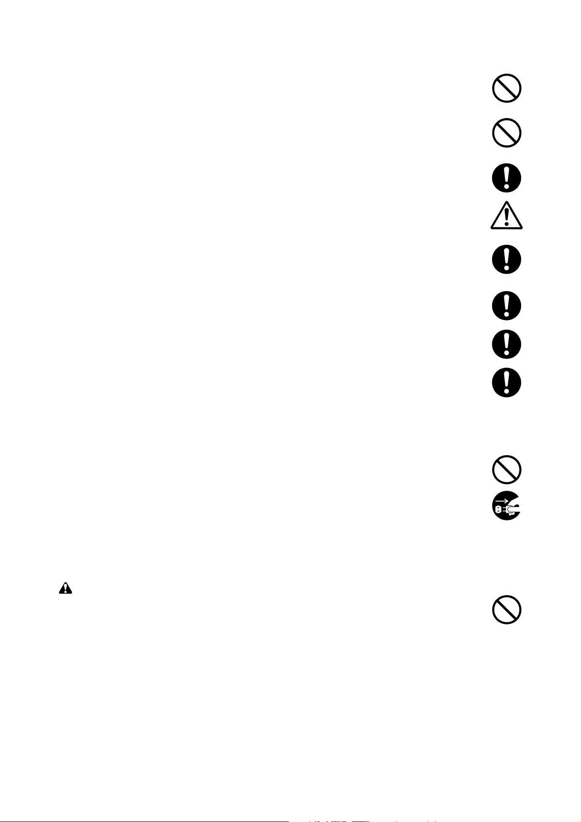
(2) Operation panel
Inch
Metric
3B0
1 APS/AMS key
2 100% key
3 Preset R/E key
4 Message display
5 Original Image Type key
6 Auto Exp. key (indicator)
7 Media key
8 Paper Source key
9 Cut Size key
0 */Language key
! Editing key
@ Output Adj. key
# Program Recall key
$ Cursor keys
% OK key
^ Memory indicator
& Repeat Copy key (indicator)
* Add Job key (indicator)
( Sort/Group key (indicator)
) Interrupt key (indicator)
⁄ Preview Copy key (indicator)
¤ Energy Saver key (indicator)
‹ Start key
› Reset key
fi Stop/Clear key
fl Light/Dark indicators
‡ Copy contrast indicators
° Copy contrast keys
· Scan indicator
‚ Copier/Printer/Scanner key (indicator)
ΠNumeric keys
„ Roll Cut key
´ Scan Stop key
Figure 1-1-2
1-1-3
Page 13

3B0
1-1-3 Machine cross sectional view
Optical section
Original conveying section
Figure 1-1-3 Machine cross sectional view
Original conveying path
1-1-4
Page 14

1-1-4 Machine drive system
3B0
Figure 1-1-4
1 Original motor pulley
2 Original feed drive belt
3 Original feed pulley 40
4 Tension pulley 20
5 Original feed pulley 40
6 Original feed pulley 40
7 Eject pulley 26
8 Eject pulley 26
9 Original cover belt
1-1-5
Page 15
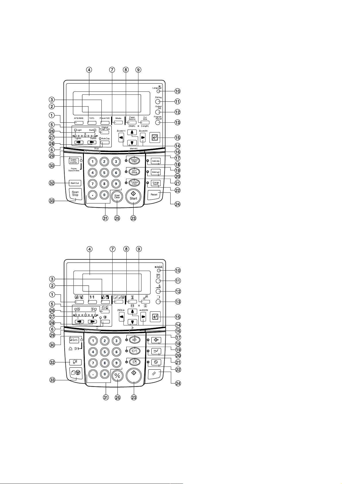
1-2-1 Installation environment
1. Temperature: 10°C – 35°C/50°F – 95°F
2. Humidity: 15% – 85% RH
3. Installation location
• Avoid locations with direct sunlight or bright areas such as near windows or with strong lighting.
• Avoid locations with high temperature or humidity, low temperature or humidity, and areas with sudden changes in
temperature. Also avoid areas with hot or cold draughts.
• Avoid areas with excessive dust or vibration.
• Be sure that the platform or floor area can support the weight of the equipment.
• Locate on a flat, horizontal surface (maximum inclination of 0.3°).
• Avoid atmosphere laden with substances that might chemically damage the equipment or the photoconductor
(mercury, alkali or acid vapors, inorganic gases, gases such as NOx and SOx, and chlorine-based organic solvents).
• Choose a location with adequate ventilation.
4. There should be sufficient space for operation and maintenance of the equipment:
800 mm/31
1
/2" at front, 500 mm/1911/16" at right and 300 mm/1113/16" at rear and left.
3B0
A
B
3
A: 1330 mm/52
/8"
C
B: 482 mm/19"
C: 643 mm/125/16"
Figure 1-2-1 Installation measurements
1-2-1
Page 16

1-3-1 Unpacking and installing the scanner
(1) Installation procedure
Unpack the scanner.
—
1
⁄
fi
3B0
#
·
%
(
^&
1 Machine body
2 Original loop guide
3 Scanner interface PCB ass'y
4 Junction wiring A, interface PCB
5 Junction wiring B, interface PCB
6 Junction wiring, scanner power
supply
7 Junction wiring, printer unit
8 DIMM
9 Clamp, EMT-3N
0 Clamp, GNK-5N
! Open bushing
$
(
¤
^*
45
67
·
Figure 1-3-1
@ BVM4 × 06 cross-head
bronze binding screws
# Outer case
$ Skid
% Bottom pad
^ Pad A
& Pad B
* Pad C
( Pad D
) Accessory case
⁄ Machine cover
)
3fl
90!
@‡
2‹
¤ Barcode label
‹ Polyethylene bag
› Hinge joints
fi Air cap bag
fl Air cap bag
‡ Vinyl bag
° Top board
· Pad E
‚ Polyethylene bag
ΠAir cap bag
„ Installation guide
¤
›
‚
„
8Œ
1-3-1
Page 17
3B0
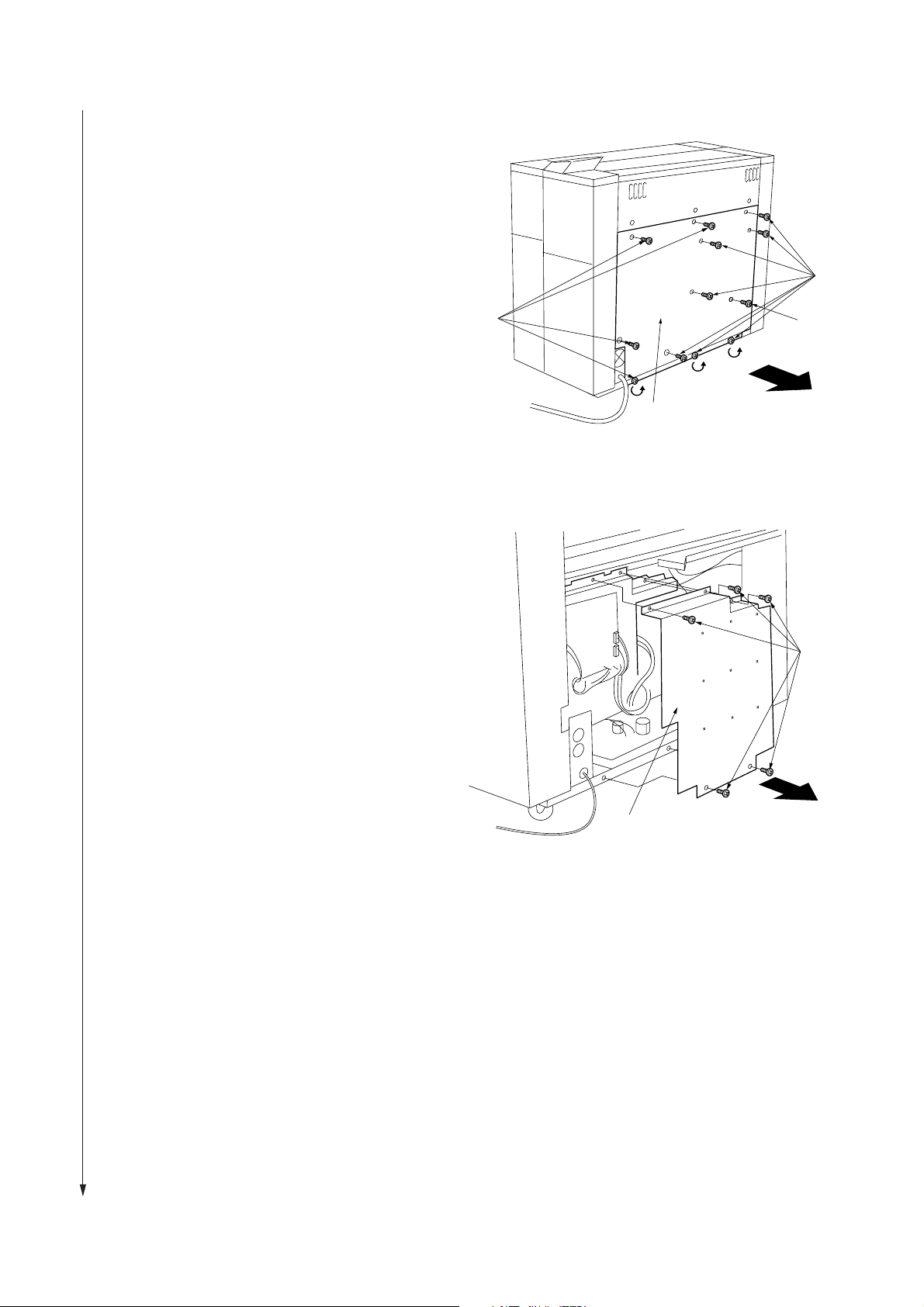
Screws
Main PCB cover
1. Remove eight screws and M4 × 6 raised
binding screw, loosen the three screws at the
bottom, and remove the rear cover.
Screws
2. Remove five screws, and remove the main PCB
cover.
Screws
M4 × 6 raised
binding screw
Rear cover
Figure 1-3-2
1-3-2
Figure 1-3-3
Page 18
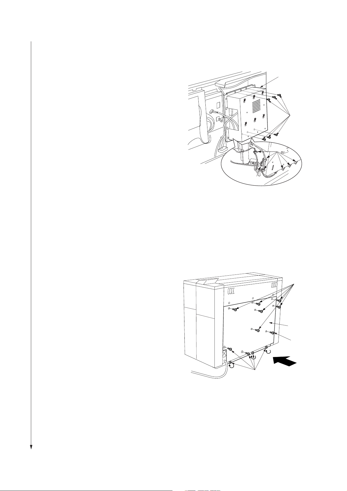
3. From the rear side of the main body, unlock the
clamps at the lower left of the controller cover
located at the right side, remove the connector
and the six screws, and then remove the
controller cover.
3B0
Controller cover
Screws
Clamps
Connector
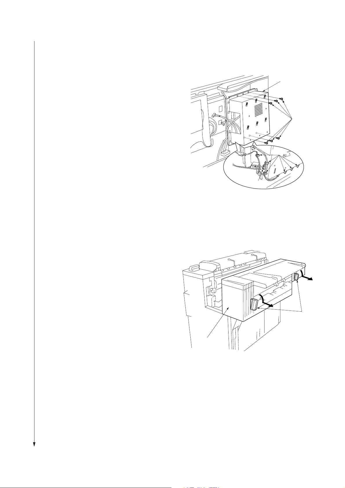
4. Lower the two levers at the front of the main
unit (pull them out and down), and pull out the
attachment unit.
Figure 1-3-4
Levers
Attachment unit
Figure 1-3-5
1-3-3
Page 19
3B0
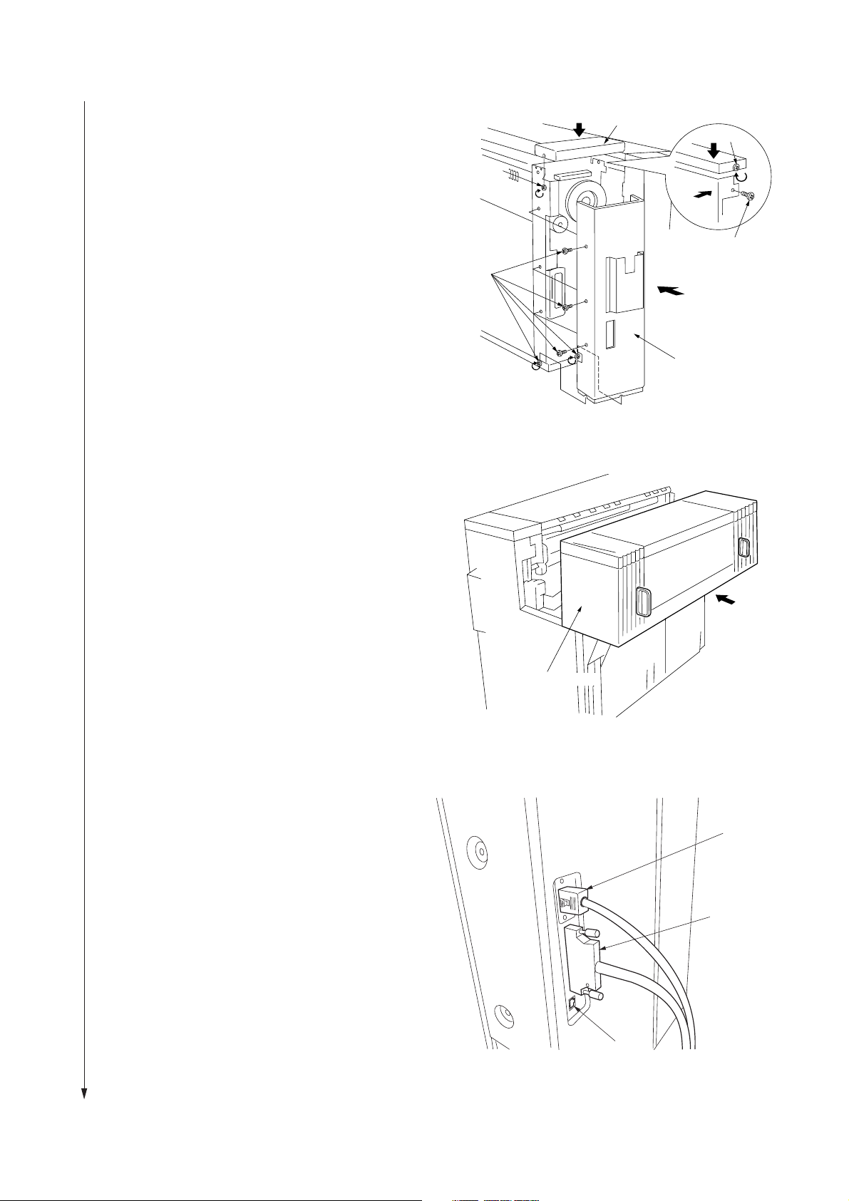
5. Loosen two screws and remove the main unit's
left rear upper cover.
6. Remove four screws, loosen two screws, and
remove the main unit's left rear lower cover.
Left rear
upper cover
Screw
Screw
Screw
Screws
Left rear
lower cover
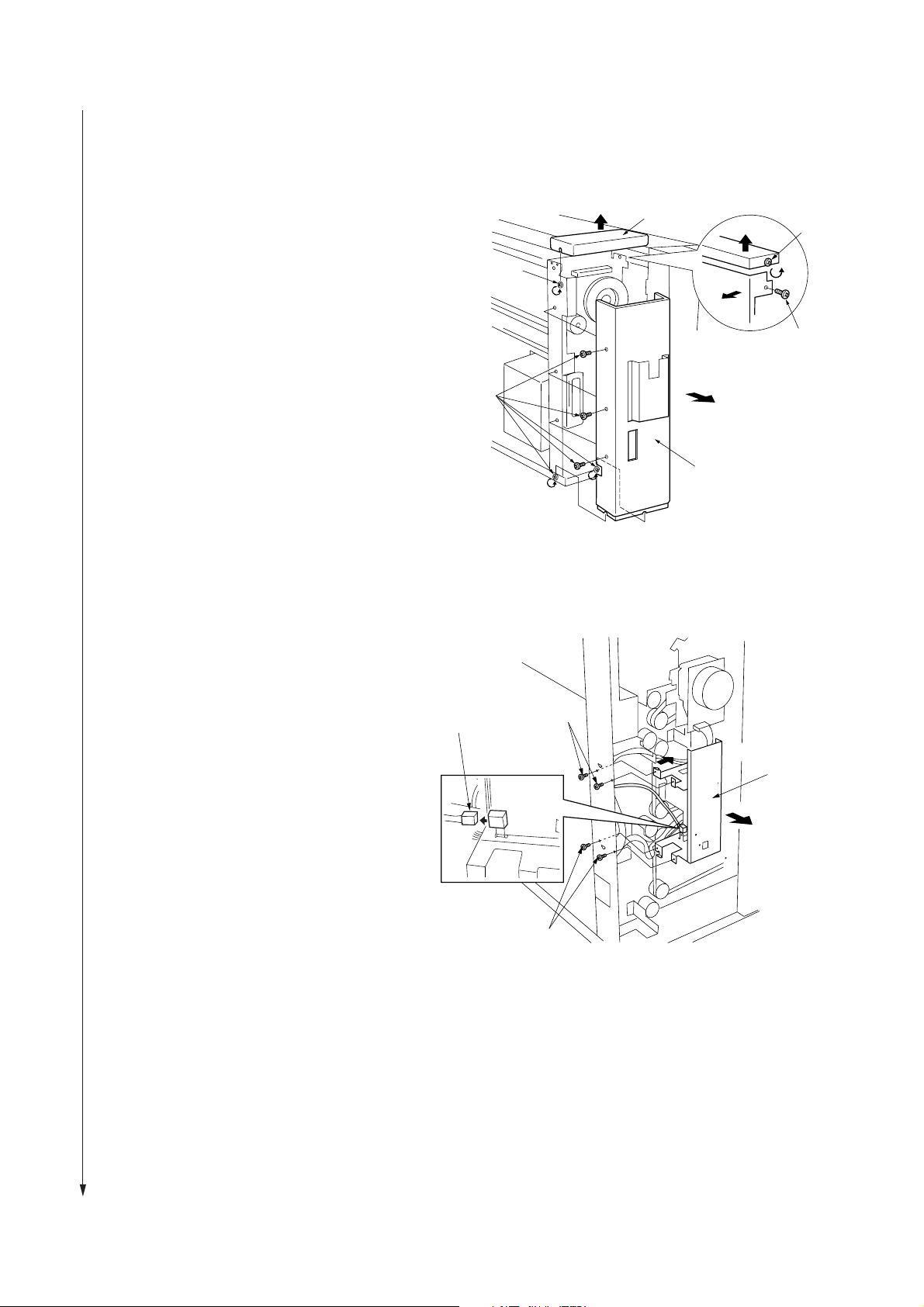
7. Remove four screws , and remove the scanner
interface retainer .
8. Remove the network connector.
Network connector
Figure 1-3-6
Screws
Scanner interface
retainer
Screws
Figure 1-3-7
1-3-4
Page 20

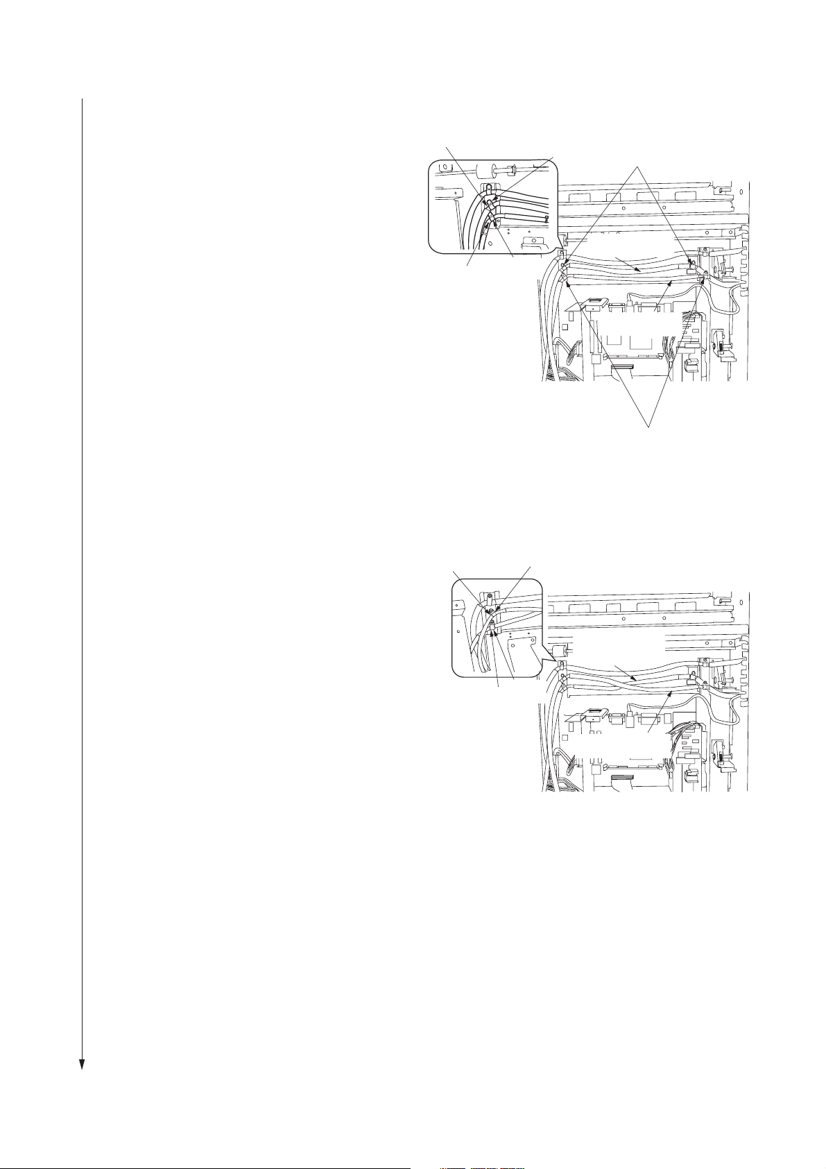
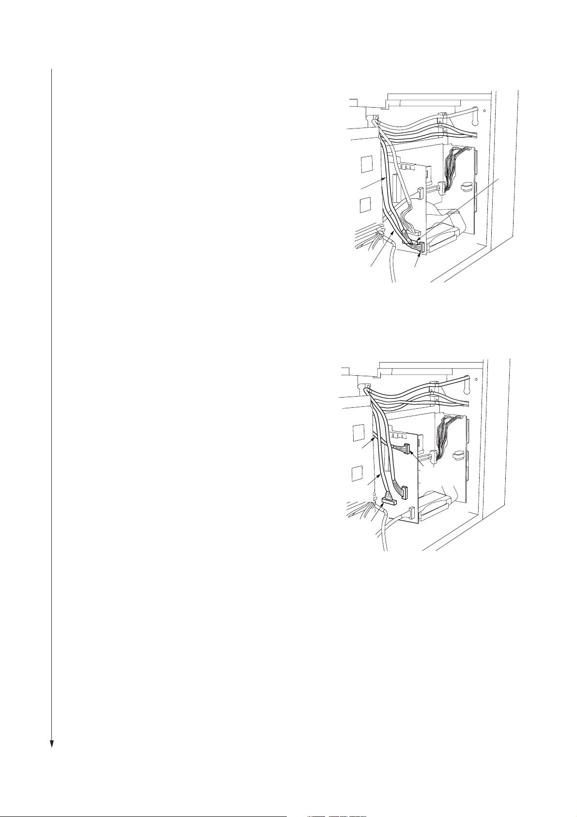
9. Put the 9-pin connector side of the Junction
Wiring and Printer Unit near the main PCB and
the 6-pin connector side near the right side of
the controller unit, and then lock the seven wire
saddles and lay it down.
3B0
Juction Wiring and
Printer unit
10. Insert DIMM into the memory slot of the
controller unit until the hooks on both sides are
closed.
9 pin
Memory slot
Hook
Figure 1-3-8
DIMM
Figure 1-3-9
Wire saddles
6 pin
Hook
11. Put the connectors of the Junction Wiring A,
Interface PCB and the Junction Wiring B,
Interface PCB with a binding band near the
main PCB, and pass the connectors of the
other side through the connection hole on the
main body.
*Pass the relay cable under the sheet metal so
that the cable does not hit the spring.
Junction Wiring A,
interface PCB
Binding band
Connection
hole
Junction Wiring B,
interface PCB
Figure 1-3-10
1-3-5
Page 21

3B0
12. Connect the modular connector, Junction
Wiring, Printer Unit 10-pin connector, 6-pin
connector (on the front side of scanner interface
PCB assembly), Junction Wiring B, Interface
PCB, and Junction Wiring A, Interface PCB to
the Scanner Interface PCB Assembly described
in step 11.
13. Fit the Scanner Interface PCB Assembly to the
main body with four screws.
* When fitting, pass the cord‚ between the
assembly and the main body so that the cord
does not hit the connection portion of the
Scanner Interface PCB Assembly.
Modular
connector
Junction Wiring A,
Interface PCB
Junction Wiring B,
Interface PCB
10-pin
connector
Figure 1-3-11
6-pin
connector
Screws
14. Pass the cable to be passed through the
connection hole at the rear right of the main
body through the open bushing, OCB-1000,
and fit it to the connection hole.
Cord
Screws
Figure 1-3-12
Connection hole
Open bushing
OCE-1000
Figure 1-3-13
1-3-6
Page 22
15. (120 V specifications)
Set the shield area of the Junction Wiring A,
Interface PCB with the clamp, GNK-5N and the
shield area of the Junction Wiring B, Interface
PCB with the clamp, EMT-3N, and fix them with
four binding screws M4 × 6.
Junction Wiring A,
interface PCB
Junction Wiring B,
interface PCB
Clamp,
EMT-3N
Clamp,
GNK-5N
3B0
Shield area
Junction Wiring A,
interface PCB
Junction Wiring B,
interface PCB
Shield area
(230 V specifications)
Bind the shield area of the Junction Wiring A,
interface PCB with the clamp, GNK-5N and at
the upper right and at the lower left, fix it with
two binding screws M4 × 6.
Bind the shield area of the Junction Wiring B,
interface PCB with the clamp, EMT-3N and at
the lower right and at the upper left, fix it with
two binding screws M4 × 6.
Junction Wiring B,
interface PCB
Junction Wiring A,
interface PCB
Figure 1-3-14
Clamp,
EMT-3N
Junction Wiring A,
interface PCB
Clamp,
GNK-5N
Junction Wiring B,
interface PCB
Figure 1-3-15
1-3-7
Page 23
3B0
16. (For 120V Specifications)
Connect the Junction Wiring A, Interface PCB
with a binding band to CN5, and connect the
Junction Wiring B, Interface PCB with a binding
band to CN4.
* When connecting them, support the IPU PCB
with your hand.
(For 230V Specifications)
On the plotter IPU PCB, connect the connector
of the Junction Wiring B, Interface PCB with a
binding band to the JPEG connector, and
connect the connector of the Junction Wiring A,
Interface PCB with a binding band to the
scanner connector.
* When connecting them, support the IPU PCB
with your hand.
Junction Wiring A,
interface PCB
Junction Wiring B,
interface PCB
Junction Wiring A,
interface PCB
Junction Wiring B,
interface PCB
CN5
CN4
Figure 1-3-16
Scanner
connector
1-3-8
JPEG
connector
Figure 1-3-17
Page 24

17. On the Junction Wiring, Printer Unit, connect
the connector at the lower part of the main PCB
located at the rear of the main body to the 10pin connector and connect the connector to the
9-pin connector.
* If the connector has been already connected
on the main body, disconnect it and then
connect it to the Junction.
Connector
Connector
10-pin
connector
9-pin
connector
Connector
3B0
9-pin
connector
18. Reattach the main PCB cover with five screws.
Figure 1-3-18
Screws
Main PCB cover
Figure 1-3-19
1-3-9
Page 25
3B0
19. Fit the controller cover with six screws, lock the
lower left six clamps on the right controller
cover from the rear side of the main body, and
connect the connector.
Controller
cover
Screws
Clamps
Connector
20. Reattach the rear cover, using M4 × 6 raised
binding screws and the eleven screws that you
removed or loosened at step 1.
Figure 1-3-20
Screws
Rear cover
M4 × 6 raised
binding screw
1-3-10
Screws
Figure 1-3-21
Page 26
3B0
Connector
Connector
Ethernet cable
21. Reattach the main unit's left rear lower cover
with six screws.
22. Reattach the main unit's left rear upper cover by
tightening its two screws.
23. Close the attachment unit securely.
Left rear upper cover
Screw
Screw
Screw
Screws
Left rear
lower cover
Figure 1-3-22
24. Connect the ethernet cable, the connector and
the connector at the left rear of the main body
respectively.
25. Run the maintenance item U065, U066 and
U067 on operation panel of this product, and
then enter the value of data sheet with this
product.
Attachment unit
Figure 1-3-23
Figure 1-3-24
1-3-11
Page 27

3B0
1-3-2 Copy mode initial settings
The factory settings for this machine are as shown below.
Maintenance
item No.
U256
U258
U267
U269
U271
U273
U344
User settings
Contents Setting at factory
Auto Preheat Time
Switching copy operation at toner empty detection
Adjusting the cutting length for the paper leading edge
Selecting the timing for total counting
Setting the unit of counting
Setting the maximum paper length
Setting the preheat (energy saving) mode
Auto Clear Time
Auto Shut-off Time
Copy size adjustment
Fusing temperature
Custom media type
Standard size set
Auto roll over
Buzzer
Management #
ON
Single
Length by temp.
Paper feeding
Total count: 0.1
Key counter: 0.1
Paper length Ltd.: 6000
Returnable Len. L: 1400
Energy save
ON
Shut off mode
0.0%
Plain: 155°C
Vellum: 185°C
Film: 150°C
Custom: 165°C
Vellum
A sizes/Architecture
OFF
ON
4850
1-3-12
Page 28
3B0
1-3-3 User Settings
The user can make default settings that determines how the copier acts when the main switch is turned on or after the reset
key is pressed. Default settings are categorized as “Machine default” that determine the copier’s basic operations and
“Copy default” which determine operability. Default settings are also divided into “user” and “manager” defaults, this former
being available to all users while this latter is restricted to only certain users. To make “manager defaults”, you need to input
a management No.
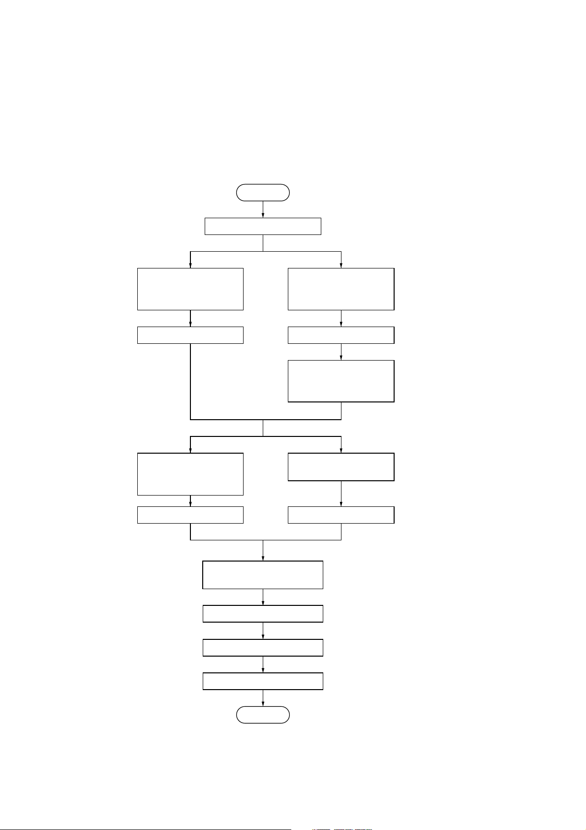
(1) Default settings making procedure
Start
Press the */Language key.
Select “Default setting/
user” using the cursor
up/down keys.
Press the OK key.
Select “Machine default”
using the cursor up/down
keys.
. . . . .
Set the default setting mode.
Select “Default set/manager”
using the cursor up/down
keys.
Press the OK key.
Enter management
No. (default: 4850) using
the numeric keys.
Select “Copy default” using
the cursor up/down keys.
Press the OK key.
Select item using the cursor
up/down keys.
Press the OK key.
Make the default setting.
Press the */Language key.
End
Press the OK key.
. . . . .
Exits the default setting mode.
1-3-13
Page 29

3B0
(2) Making default settings
Machine default
Items common to user/manager
Paper width adjustment
1. Select a paper source and press the OK key.
2. Select between “Auto” and “Input width (# key)”,
and press the OK key.
3. If having selected “Input width (# key)”, input the
width using the numeric keys and press the OK
key.
Setting range: 210 to 920 mm (8.5" to 36.2")
Media Type [Paper working]
1. Select between “ON” and “OFF”, and press the
OK key.
Media type setting [Paper material adjustment]
First turn “ON” Media Type.
1. Select a paper source and press the OK key.
2. Select a paper type and press the OK key.
Paper type: Plain, Vellum, Film, Custom
Items for managers only
Auto Clear Timer [Auto clear time]
1. Select between “ON” and “OFF”, and press the
OK key.
Auto Shut-off Time [Auto shutoff time]
1. Select between “Shut off mode”, “Sleep mode”,
and “OFF”, and press the OK key.
Timer Set
First turn “ON” Auto Clear Timer and set Auto
Shut-off Time to the setting other than “OFF”.
Auto Clear Time
1. Select “Auto Clear Time” and press the OK key.
2. Select a time and press the OK key.
Setting range: 30 s, 1 min, 3 min, 5 min
Auto Preheat Time
1. Select “Auto Preheat Time” and press the OK
key.
2. Select a time and press the OK key.
Setting range: Any 5 min mark between 5 and
45 min
Set Auto Preheat Time shorter than Auto Shut-off
Time.
Auto Shut-off Time
1. Select “Auto Shut-off Timer” and press the OK
key.
2. Select a time and press the OK key.
Setting range: Any 5 min mark between 15 and
120 min
Copy size adjustment
1. Select a paper type and press the OK key.
Paper type: Plain, Vellum, Film, Custom
2. Change the size and press the OK key.
Setting range: –3.0 to +3.0%
Roll end adjustment
1. Select a paper type and press the OK key.
2. Select between “Fix” and “Unfix”, and press the
OK key.
Display contrast
1. Select a contrast level and press the OK key.
Setting range: 1 to 7
Orig. eject direct
1. Select between “Discharge to back” [“Output to
back”] and “Discharge to front” [“Output to
front”], and press the OK key.
Fusing temperature [Set fixing temp.]
1. Select a paper type and press the OK key.
Paper type: Plain, Vellum, Film, Custom
2. Select a temperature and press the OK key.
Plain: 145°C, 155°C, 165°C
Vellum: 165°C, 175°C, 185°C
Film: 150°C, 160°C, 170°C
Custom: Select a temperature based on settings in
Custom media type.
Custom media type [Custom. pap. material]
1. Select “Custom” as the paper type and press
the OK key.
2. Select a fixing temperature and press the OK
key.
3. Adjust magnification and press the OK key.
Standard size set
1. Select between “Architecture” [“A sizes”] and
“Engineer” [“B sizes”], and press the OK key.
Auto roll over
1. Select between “ON” and “OFF”, and press the
OK key.
Buzzer
1. Select between “ON” and “OFF”, and press the
OK key.
Management # [Manage. code]
1. Enter a new 4-digit management No. using the
numeric keys and press the OK key.
If you press the stop/clear key before the OK key,
the management No. reverts back to the default
(4850).
1-3-14
Page 30

Copy default
Items common to user/manager
3B0
Auto rotation mode [Auto rotation]
1. Select between “ON” and “OFF”, and press the
OK key.
Zoom step [Zoom steps]
1. Select between “1%” and “0.1%”, and press the
OK key.
Zoom register
1. Select a user No. and press the OK key.
2. Select between “Zoom” and “XY Zoom”, and
press the OK key.
3. Set the magnification.
Zoom
Enter the zoom ratio using the cursor left/right keys
and the numeric keys, and press the OK key.
XY Zoom
Select a direction using the cursor up/down/left/
right keys, enter the zoom ratio using the cursor
up/down/left/right keys and the numeric keys, and
press the OK key.
Cut size register
1. Select between “User-1” and “User-2”, and
press the OK key.
2. Enter the cut size using the numeric keys and
press the OK key.
Setting range: 297 to 6000 mm (11 to 237")
Exposure step [Exposure steps]
1. Select between “7 steps” and “13 steps”, and
press the OK key.
Auto/Manual exp.
1. Select an original mode and press the OK key.
Original mode: Auto, Normal, Normal darker,
Normal lighter, Text/Line, Photo
Default exposure
First set Auto/Manual exp. to the setting other than
“Auto”.
1. Select an exposure level and press the OK key.
Setting range: 1 to 7
Exposure adj.
1. Select an original mode and press the OK key.
Original mode: Auto exposure, Normal originals,
Character/Line, Photo
2. Select an exposure level and press the OK key.
Setting range: 1 to 7
Items for manager only
Standard drawer
1. Select a paper source and press the OK key.
Paper source: 1st paper drawer*, 2nd paper
drawer, 3rd paper drawer, Bypass
* Optional
Auto select set
1. Select a copy mode and press the OK key.
Copy mode: APS, AMS, Manual
AMS mode
1. Select between “ON” and “OFF”, and press the
OK key.
Method copy start
1. Select between “Auto start” and “Start key”, and
press the OK key.
Start late time
First set Method copy start to “Auto start”.
1. Select a time and press the OK key.
Setting range: 0.5 s, 1 s, 2 s, 3 s, 4 s, 5 s
Paper cut [Select cut. Method]
1. Select a cutting mode and press the OK key.
Setting range
When “A sizes” (metric) is set: Synchronized cut,
1189 mm, 841 mm, 594 mm, 420 mm, 297 mm,
User-1, User-2
When “B sizes” (metric) is set: Synchronized cut,
1030 mm, 728 mm, 515 mm, 364 mm, User-1,
User-2
When “Architecture” (inch) is set: Synchronized
cut, 12.0", 18.0", 24.0", 36.0", 48.0", User-1,
User-2
When “Engineer” (inch) is set: Synchronized cut,
11.0", 17.0", 22.0", 34.0", 44.0" , User-1, User-2
Sync. Cut length
1. Select between “ON” and “OFF”, and press the
OK key.
Delete memory
1. Select between “Delete” and “Confirm before
deleting” [“Check data of repeat copy”], and
press the OK key.
Per rep copy [Permit repeat]
1. Select a mode and press the OK key.
Setting range: Permit, Code number, Deny
[Unpermit]
1-3-15
Page 31

3B0
Chg rep. copy # [Repeat codechange]
First set Per rep copy to “Code number”.
1. Enter a new 4-digit code No. using the numeric
keys and press the OK key.
If you press the stop/clear key before the OK key,
the code No. reverts back to the default (4850).
Memory compress
1. Select a compression mode and press the OK
key.
Setting range: Low-compression, Standard-compression, High-compression
Maximum Jobs
1. Select a max. number of jobs and press the OK
key.
Setting range: 5 Jobs, 10 Jobs, 20 jobs
Edit Function defaults [Default of edit. function]
Image Shift up/down
1. Select “Image Shift up/down” and press the OK
key.
2. Switch between the up and down direction
using the cursor up/down keys.
3. Enter a shift range using the numeric keys and
press the OK key.
Setting range 1 to 200 mm (0.1 to 8.0")
Image shift L/R
1. Select “Image shift up L/R” and press the OK
key.
2. Switch between the left and right direction using
the cursor left/right keys.
3. Enter a shift range using the numeric keys and
press the OK key.
Setting range 1 to 200 mm (0.1 to 8.0")
Leading edge
1. Select “Leading edge” and press the OK key.
2. Switch between “+” and “–” using the cursor up/
down keys, enter a size using the numeric keys
and press the OK key.
Setting range –200 to +200 mm (–8.0 to +8.0")
Trailing edge
1. Select “Trailing edge” and press the OK key.
2. Switch between “+” and “–” using the cursor up/
down keys, enter a size using the numeric keys
and press the OK key.
Setting range –200 to +200 mm (–8.0 to +8.0")
Border erase
1. Select “Border erase” and press the OK key.
2. Enter a size using the numeric keys and press
the OK key.
Setting range 0 to 200 mm (0.1 to 8.0")
Adj. preview copy
1. Select between “Preview contrast” and
“Preview image”, and press the OK key.
Reduce length Ldt.
1. Enter the length of the original using the
numeric keys and press the OK key.
Setting range 2500 to 6000 mm (98.4 to 237.0")
1-3-16
Page 32

1-4-1 Maintenance mode
The copier is equipped with a maintenance mode which can be used to maintain and service the machine.
(1) Executing a maintenance item
Start
3B0
Enter “10871087”.
Use the numeric keys or the cursor
up/down keys to enter the number of
the maintenance item to be executed.
Press the start key.
That maintenance item will be run.
Press the stop/clear key.
Yes
Run that item again?
- - - - - Entering the maintenance mode
- - - - - Selecting the maintenance item
No
Yes
Use the numeric keys or the cursor
up/down keys to enter “001”, and then
press the start key
Run another
maintenance item?
No
End
- - - - - Exiting the maintenance mode
1-4-1
Page 33

3B0
(2) Maintenance mode item list
Section
General
Initialization
Drive, paper
feed, paper
conveying and
cooling
systems
Item
No.
U000 Printing out an own-status report ———
U001 Exiting the maintenance mode ———
U003 Setting the service telephone number ———
U004 Setting the machine model number ———
U005 Copying without paper ———
U019 Displaying the ROM version ———
U020 Initializing all data ———
U030 Checking the operation of the motors ———
U031 Checking switches for paper conveying ———
U032 Checking the operation of the clutches ———
U033 Checking the operation of the solenoids ———
U034 Adjusting the print start timing Roll: –5
U037 Checking the operation of the fan motors ———
U038 Checking safety switches ———
U039 Adjusting printing magnification
U040 Adjusting the synchronized cut length 0
U041 Adjusting the standard cut length Normal/1/S: 0
Content of maintenance item Initial setting*
Bypass: 2
Normal/MAIN SCAN: 0
Normal/SUB SCAN: 0
Vellum/MAIN SCAN: 0
Vellum/SUB SCAN: 0
Film/MAIN SCAN: 0
Film/SUB SCAN: 0
Normal/1/M: 0
Normal/1/L: 0
Normal/2/S: 0
Normal/2/M: 0
Normal/2/L: 0
Normal/3/S: 0
Normal/3/M: 0
Normal/3/L: 0
Vellum/1/S: 0
Vellum/1/M: 0
Vellum/1/L: 0
Vellum/2/S: 0
Vellum/2/M: 0
Vellum/2/L: 0
Vellum/3/S: 0
Vellum/3/M: 0
Vellum/3/L: 0
* Initial setting when executing maintenance item U020.
1-4-2
Page 34

3B0
Section
Drive, paper
feed, paper
conveying and
cooling
systems
Optical
High voltage
Developing
Fixing and
cleaning
Item
No.
U041 Adjusting the standard cut length Film/1/S: 0
U044 Adjusting the long copy cut length PLAIN PAPER: 0
U045 Checking paper size switches ———
U060 Adjusting the input gamma Copier: 0
U061 Checking the operation of the xenon lamps ———
U065 Adjusting the scanning magnification Main scan (%): 0
U066 Adjusting the scanner leading edge registration 0
U067 Adjusting the optical axis (center line) 0
U073 Checking the operation of the original motor ———
U077 Checking the switches for original conveying ———
U079 Checking the shading operation ———
U090 Checking the AGC processing operation ———
U100 Setting the drum surface potential Grid data: 158
U101 Turning the transfer/separation charger on ———
U105 Forcing the cleaning lamps to be turned on ———
U111 Checking/Clearing the drum drive time 0
U129 Turning potential correction on/off ON
U130 Initial setting for the developer ———
U131 Changing the initial setting for the developer Control: 120
U132 Forcing toner to be replenished ———
U135 Checking the operation of the toner feed motor ———
U139 Displaying thermistor temperatures ———
U140 Adjusting the developing bias ———
U155 Displaying the toner sensor output ———
U156 Changing the toner density control data Adjust: 0
U157 Checking/Clearing the developing section drive time 0
U158 Checking/Clearing the developing count 0
U160 Coating the cleaning blade with toner ———
U162 Forced stabilization ———
U163 Releasing the fixing section error state ———
U196 Checking the operation of the fixing heater ———
U199 Displaying the fixing unit thermistor temperatures ———
Content of maintenance item Initial setting*
Film/1/M: 0
Film/1/L: 0
Film/2/S: 0
Film/2/M: 0
Film/2/L: 0
Film/3/S: 0
Film/3/M: 0
Film/3/L: 0
VELLUM: 0
FILM: 0
Scanner: 0
Sub scan (%): 0
Target Level: 200
LPH: 7
* Initial setting when executing maintenance item U020.
1-4-3
Page 35

3B0
Section
Operation
panel/Optional
units
Mode setting
Image
processing
Item
No.
U200 Turning all LEDs on ———
U204 Turning the key card/key counter option on/off OFF
U213 Checking the operation of the counters ———
U214 Checking the upper roll unit ———
U245 Checking messages ———
U250 Setting the maintenance cycle 3000 m
U251 Checking/Clearing the maintenance count 0
U252 Setting the region of use JAPAN METRIC
U256 Turning the auto preheat function on/off ON
U258 Switching copy operation at toner empty detection Single
U262 Ignoring a call for service detection ———
U267 Adjusting the cutting length for the paper leading edge Length by temp.
U269 Selecting the timing for total counting Paper feeding
U271 Setting the unit of counting Total count: 0.1
U272 Turning the upper roll unit option on/off OFF
U273 Setting the maximum paper length Paper length Ltd.:
U344 Setting the preheat (energy saving) mode Energy save
U400 Adjusting the image width in the main scanning direction 0
U406 Adjusting the trailing edge margin Trailing edge: 0
U450 Selecting the PG mode ———
U451 PG gray printout ———
U452 PG 16-level grayscale printout ———
U454 Adjusting the exposure amount Normal original: 0
U455 Adjusting the automatic exposure Base: 3
U457 Adjusting the filter gain Normal original: 10
U459 Adjusting the output gamma 0
U461 Adjusting the focus and measuring the solid-black density ———
U462 Printing PG to check LPH operation
U470 Setting the data compression ratio 80
U475 Setting the stain compensation mode MODE1
U476 Setting the photo mode scanning width MODE1
Content of maintenance item Initial setting*
Key counter: 0.1
6000
Returnable Len. L:
1400
Character/Line: 0
Photo: 0
Character/Line: 10
Photo: 0
* Initial setting when executing maintenance item U020.
1-4-4
Page 36

3B0
Other
Section
Item
No.
U901 Checking/Clearing total copy counts by paper feed location 0
U903 Checking/Clearing the paper jam counts 0
U904 Checking/Clearing the call for service counts 0
U908 Checking/Clearing the total count 0
U916 Clearing all counts ———
U969 Adjusting CF service call count ———
U991 Checking/Clearing the scan count 0
U993 Printing out all PGs ———
U999 Checking the memory ———
Content of maintenance item Initial setting*
* Initial setting when executing maintenance item U020.
1-4-5
Page 37

3B0
(3) Contents of maintenance mode items
Item No.
U000 Printing out an own-status report
Description
Prints out a list of the current settings of all maintenance items, and occurrences of paper jams and service
calls.
Purpose
To check the current setting of the maintenance items, or the occurrences of paper jams and service calls.
Before initializing or replacing the backup ROM, print out a list of the current settings of the maintenance items
so that you can reenter the same settings after initialization or replacement.
Method
1. Press the start key. The screen that allows you to select the desired item will be displayed.
2. Use the cursor up/down keys to select the item that you want to print out.
Display List to be printed out
Maintenance List of the current settings of all maintenance items
JAM List of paper jams
Service Call List of service calls
User default List of current user settings
3. Press the start key. The test copy screen will be displayed.
4. Press the start key. The selected list will be printed out.
Description and Procedure
Maintenance
JAM
Service Call
User default
Figure 1-4-1 Own-status report
1-4-6
Completion
Press the stop/clear key.
Page 38

3B0
Item No.
U001 Exiting the maintenance mode
Description
Exits the maintenance mode and returns to the normal copy mode.
Purpose
To exit the maintenance mode.
Method
Press the start key.
• The machine will enter the normal copy mode.
U003 Setting the service telephone number
Description
Sets the telephone number to be displayed when a service call code is detected.
Purpose
To set (during initial set-up of the machine) the telephone number for contacting service.
Method
Press the start key.
• The currently set telephone number will be displayed.
Setting
1. Use the numeric keys and the keys shown below to enter a telephone number (up to 16 digits).
• Use the cursor left/right keys to move the cursor and the cursor up/down keys to select the desired
number or symbol.
• The display at the cursor position will scroll through the numbers and symbols shown below each time the
cursor up/down keys are pressed.
Description and Procedure
Key Numbers/Symbols
Numeric keys 0 to 9
APS/AMS key *
100% key #
Preset R/E key [
Media key ]
Paper source key Cut size key (space)
2. Press the start key and set the telephone number. If you want to cancel the telephone number setting,
press the stop/clear key.
U004 Setting the machine model number
Description
Displays and changes the machine model number.
Purpose
To check, as well as to set, the machine model number.
Method
Press the start key.
• The current machine model number will be displayed.
Setting
1. Use the numeric keys to enter the lowest 6 digits of the machine model number. (If you want to clear the
current machine model number, press the reset key.)
• It is not necessary to enter the first 2 digits (“37”) of the machine model number.
2. Press the start key and set the machine model number.
Completion
Press the stop/clear key.
1-4-7
Page 39

3B0
Item No.
U005 Copying without paper
Description
Initiates copy operation without paper feed.
Purpose
To check the overall operation of the machine.
Method
1. Press the start key.
2. Press the interrupt key. The test copy screen will be displayed.
3. Remove all the paper from the paper source.
4. Select the operation conditions on the test copy screen.
• Set the number of copies to be made to 99 for continuous operation.
5. Press the start key. Test copying will start.
• Copy operation will be initiated without paper under the set conditions and the original conveying section
will feed the original accordingly.
Completion
Press the stop/clear key.
U019 Displaying the ROM version
Description
Displays the part number for the ROM fitted to each PCB.
Purpose
To check the part number or to decide, based on the last digit of the number, if the newest version of ROM is
installed.
Method
1. Press the start key.
2. Use the cursor up/down keys to switch between screens and select the ROM that you want to check.
• The part number for the ROM will be displayed.
Description and Procedure
Display Description
Engine Part number and version for the engine’s ROM
Main Part number and version for the main ROM
Scanner/MMI Part number and version for the scanner/MMI
HDC Part number and version for the HDC
Font Part number and version for the font ROM
Engine boot Part number and version for the engine boot
Main boot Part number and version for the main boot
Scanner/MMI boot Part number and version for the scanner/MMI boot
Option font Part number and version for the optional font ROM
Completion
Press the stop/clear key.
U020 Initializing all data
Description
Initializes the backup ROM on the engine main PCB in order to return to the factory default settings.
Purpose
Use when replacing the engine main PCB.
Method
1. Press the start key.
2. Use the cursor up/down keys to select “Action”.
• If you want to cancel the initialization, select “Cancel”.
3. Press the start key.
• All data in the backup ROM will be initialized and the screen for selecting a maintenance item No. will be
displayed again.
1-4-8
Page 40

3B0
Item No.
U030 Checking the operation of the motors
Description
Drives each motor.
Purpose
To check the operation of each motor.
Method
1. Press the start key.
2. Use the cursor up/down keys to select the motor that you want to check.
Display Operation
Main/Drum motor The main motor (MM), drum motor (DM), and developing
bias are turned on.
Fixing motors The fixing motor (FM) is turned on.
Feed motors The paper feed motor (PFM) is turned on.
3. Press the start key.
• The selected motor is turned on.
4. When you want to stop the motor, press the stop/clear key.
Completion
Press the stop/clear key.
U031 Checking switches for paper conveying
Description
Displays the on/off status of each paper detection switch on the paper path.
Purpose
To check the operation of the switches for paper conveying.
Method
1. Press the start key.
2. Use the cursor up/down keys to switch between screens and select the switch that you want to check.
3. Turn each switch on and off manually to check its status.
• When a switch is detected to be in the on position, the display for that switch will be highlighted.
Description and Procedure
Display Switch name
Pulse se. 1 Upper paper empty switch* (PESW-U)
Pulse se. 2 Middle paper empty switch (PESW-M)
Pulse se. 3 Lower paper empty switch (PESW-L)
Lead 1 Upper paper feed switch (PFSW-U)
Lead 2 Middle paper feed switch (PFSW-M)
Lead 3 Lower paper feed switch (PFSW-L)
Resist Registration switch (RSW)
Output Eject switch (ESW)
Lead Bp Bypass timing switch (BTSW)
BPResi. Bypass registration switch (BRSW)
* Optional
Completion
Press the stop/clear key.
1-4-9
Page 41

3B0
Item No.
U032 Checking the operation of the clutches
Description
Turns each clutch on.
Purpose
To check the operation of each clutch.
Method
1. Press the start key.
2. Remove all the paper from the paper source.
3. Use the cursor left/right keys to switch between screens and select the clutch that you want to check.
4. Use the cursor up/down keys to select the clutch that you want to check.
• The display for the selected clutch will be highlighted.
5. Press the start key.
• The selected clutch will be turned on for 1 second and the paper feed motor (PFM) will be turned on as
well.
Display Clutch name
feed 1 Upper feed clutch* (FCL-U)
feed 2 Middle feed clutch (FCL-M)
feed 3 Lower feed clutch (FCL-L)
CL1 Upper roll winding clutch* (RWCL-U)
CL2 Middle roll winding clutch (RWCL-M)
CL3 Lower roll winding clutch (RWCL-L)
Roll feed Roll feed clutch (RFCL)
Roll resi. Roll registration clutch (RRCL)
BPFeed Bypass feed clutch (BFCL)
BPResist Bypass registration clutch (BRCL)
* Optional
Completion
Press the stop/clear key.
U033 Checking the operation of the solenoids
Description
Applies current to each solenoid in order to check its on status.
Purpose
To check the operation of each solenoid.
Method
1. Press the start key.
2. Use the cursor up/down keys to select the solenoid that you want to check.
• The display for the selected solenoid will be highlighted.
3. Press the start key.
• The selected solenoid will be turned on for 1 second.
Description and Procedure
1-4-10
Display Solenoid name
Separa. of solenoids Separation claw solenoid (SSOL)
Main switch solenoid (Turns power off)
• Select “Main switch solenoid” in order to check the operation of the main switch when the auto shut-off
function engages.
Completion
Press the stop/clear key.
Page 42

3B0
Item No.
U034 Adjusting the print start timing
Method
See page 1-6-14.
U037 Checking the operation of the fan motors
Description
Drives each fan motor.
Purpose
To check the operation of each fan motor.
Method
1. Press the start key.
2. Use the cursor up/down keys to select the fan motor that you want to check.
Display Operation
LPH The LPH fan motor (LFM) is turned on.
Fixing The fixing fan motor (FFM) is turned on at full speed.
Fixing Low The fixing fan motor (FFM) is turned on at half speed.
Convey The paper conveying section fan motor (PCFM) is turned on.
3. Press the start key.
• The selected fan motor will be turned on.
4. When you want to stop the motor, press the stop/clear key.
Completion
Press the stop/clear key.
U038 Checking safety switches
Description
Displays the on/off status of each safety switch.
Purpose
To check the operation of the safety switches.
Method
1. Press the start key.
2. Open the respective covers to turn each switch on and off to check its status.
• When a switch is detected to be in the on position, the display for that switch will be highlighted.
Description and Procedure
Display Switch name Opening cover
Ori. Table Safety switches 1 and 2 (SSW1&2) Detachable unit
Fixing Safety switch 3 (SSW3) Eject cover
Dis. tank Safety switch 4 (SSW4) Right cover
F cover Safety switches 5 and 6 (SSW5&6) Front covers
Hopper Toner replenishing slot opening cover switch (OCSW) Toner replenishing slot
Original 1 Safety switches 7 (SSW7) Original cover
Original 2 Safety switches 8 (SSW8) Original leading edge cover
Completion
Press the stop/clear key.
1-4-11
Page 43

3B0
Item No.
U039 Adjusting printing magnification
Method
See page 1-6-13.
U040 Adjusting the synchronized cut length
Method
See page 1-6-16.
U041 Adjusting the standard cut length
Method
See page 1-6-15.
U044 Adjusting the long copy cut length
Method
See page 1-6-17.
U045 Checking paper size switches
Description
Displays the on/off status of each paper detection switch in the upper roller unit (optional) or middle/lower roller
units.
Purpose
To check the operation of the paper size switches.
Method
1. Press the start key.
2. Turn each switch on and off manually to check its status.
• When a switch is detected to be in the on position, the display for that switch will be highlighted.
Description and Procedure
Display Description
P.SIZE11 Upper paper size switch 1* (PSSW1-U)
P.SIZE12 Upper paper size switch 2* (PSSW2-U)
P.SIZE13 Upper paper size switch 3* (PSSW3-U)
P.SIZE14 Upper paper size switch 4* (PSSW4-U)
P.SIZE21 Paper size switch 1 (PSSW1)
P.SIZE22 Paper size switch 2 (PSSW2)
P.SIZE23 Paper size switch 3 (PSSW3)
P.SIZE24 Paper size switch 4 (PSSW4)
P.SIZE25 Paper size switch 5 (PSSW5)
* Optional
Completion
Press the stop/clear key.
1-4-12
Page 44

3B0
Item No.
U060 Adjusting the input gamma
Description
Adjusts the density at which images will be scanned in the copy operation mode or the scanner operation
mode.
Purpose
Used when the overall image is too light or too dark.
Method
1. Press the start key.
2. Use the cursor up/down keys to select the item that you want to set.
Display Setting item Setting range
Copier Adjust input gamma in the copy operation mode –15 to +15
Scanner Adjust input gamma in the scanner operation mode –15 to +15
3. Use the cursor left/right keys to change the setting as desired.
• Raising the setting value will increase the density while lowering it will decrease the density.
4. Press the start key to set the selected values.
5. Press the interrupt key. The test copy screen will be displayed.
6. Set the original and make a test copy.
Completion
Press the stop/clear key.
U061 Checking the operation of the xenon lamps
Description
Lights the right and left xenon lamps one at a time.
Purpose
To check whether the right and left xenon lamps are turned on.
Method
1. Press the start key.
2. Press the start key again.
• The right xenon lamp (XL-R) and left xenon lamp (XL-L) will light.
3. To turn the right and left xenon lamps off, press the stop/clear key.
Completion
Press the stop/clear key.
U065 Adjusting the scanning magnification
Method
See page 1-6-6.
Description and Procedure
U066 Adjusting the scanner leading edge registration
Method
See page 1-6-7.
U067 Adjusting the optical axis (center line)
Method
See page 1-6-8.
1-4-13
Page 45

3B0
Item No.
U073 Checking the operation of the original motor
Description
Operates the original motor (OM).
Purpose
To check the operation of the original conveying system.
Method
1. Press the start key.
2. Press the start key again.
• The following operations will take place every 4 seconds.
The original motor will be run normally.
The original motor will be operated in reverse.
The original motor will be turned off.
3. To turn the original motor off, press the stop/clear key.
Completion
Press the stop/clear key.
U077 Checking the switches for original conveying
Description
Displays the on/off status of each switch on the original conveying path.
Purpose
To check the operation of the switches when the original size is not detected correctly or when an original jam
occurs.
Method
1. Press the start key.
2. Turn each switch on and off manually to check its status.
• When a switch is detected to be in the on position, the display for that switch will be highlighted.
Description and Procedure
Display Switch name
Size SW4 Original size switch 4 (OSSW4)
Size SW3 Original size switch 3 (OSSW3)
Size SW2 Original size switch 2 (OSSW2)
Size SW1 Original size switch 1 (OSSW1)
Back SW Original trailing edge switch (OTSW)
Front SW Original leading edge switch (OLSW)
Completion
Press the stop/clear key.
1-4-14
Page 46

3B0
Item No.
U079 Checking the shading operation
Description
Performs the shading operation and shows the CIS channel data.
Purpose
To check the respective channel data when the solid black areas are too light or when white stripes appear on
the copy image. Also used when installing the optional book carrier.
Note
Always install the original cover when running maintenance item U079.
Method
1. Press the start key.
• After shading correction is completed, the data for each CIS channel will be displayed.
2. Use the cursor up/down keys to access the next data display.
Sample display
Data for CH1 to CH2 with the xenon lamp turning on/off
Description and Procedure
Checking Shading Correct. U079
BL/ch1 : 8
WH/ch1 : 103
BL/ch2 : 8
WH/ch2 : 105
Data for CH3 to CH4 with the xenon lamp turning on/off
Checking Shading Correct. U079
BL/ch3 : 7
WH/ch3 : 110
• When the data with the xenon lamp off is around 0 and that with the lamp on is 100 or more, the shading
operation is judged to be normal.
Completion
Press the stop/clear key.
BL/ch4 : 12
WH/ch4 : 102
Figure 1-4-2
1-4-15
Page 47

3B0
Item No.
U090 Checking the AGC processing operation
Description
Performs AGC processing and shows the CIS channel data.
Purpose
To check for an AGC error during A-D conversion.
Method
1. Press the start key.
• After AGC processing is completed, the data for each CIS channel will be displayed.
2. Use the cursor up/down keys to access the next data display.
Sample display
Data for CH1 to CH2 with the xenon lamp turning on/off
Checking AGC Correct. U090
BL/ch1 : 32
WH/ch1 : 260
Description and Procedure
BL/ch2 : 32
WH/ch2 : 255
Data for CH3 to CH4 with the xenon lamp turning on/off
Checking AGC Correct. U090
BL/ch3 : 29
WH/ch3 : 257
• When the data with the xenon lamp off is 100 or less and that with the lamp on is 250 or more, the AGC
processing operation is judged to be normal.
Completion
Press the stop/clear key.
U100 Setting the drum surface potential
Method
See page 1-6-12.
BL/ch4 : 27
WH/ch4 : 253
Figure 1-4-3
1-4-16
Page 48

3B0
Item No.
U101 Turning the transfer/separation charger on
Description
Performs transfer and separation charging.
Purpose
To check, when a transfer or separation problem occurs, whether charging is being performed correctly or not.
Method
1. Press the start key.
2. Use the cursor up/down keys to select the operation that you want to be performed.
Display Operation
TC: OFF (ON) Transfer charging
AC: OFF (ON) Separation charging
Transcript: OFF (ON) Switch between high and low transfer voltage
3. Use the cursor left/right keys to switch between the off and on display, or switch between on and off for
“Transcript”.
4. Press the start key.
• The selected charging operation will be performed.
5. When you want to stop the charging operation, press the stop/clear key.
Completion
Press the stop/clear key.
U105 Forcing the cleaning lamps to be turned on
Description
Turns the right, middle and left cleaning lamps on.
Purpose
To check, when an offset appears in the image, the operation of the cleaning lamps.
Method
1. Press the start key.
2. Press the start key again.
• The right cleaning lamp (CL-R), middle cleaning lamp (CL-M) and the left cleaning lamp (CL-L) will be
turned on.
3. To turn the right, middle and left cleaning lamps off, press the stop/clear key.
Completion
Press the stop/clear key.
U111 Checking/Clearing the drum drive time
Description
Displays and clears the drum drive time.
Purpose
To check usage conditions of the drum, as well as to clear the drum drive time after replacing the drum during
the periodic maintenance service.
Method
Press the start key.
• The current drum drive time (minute) will be displayed.
Clearing the drive time
1. Use the numeric keys to enter “0” or press the reset key.
2. Press the start key to clear the drum drive time.
• If you want to cancel the operation to clear the drum drive time, press the stop/clear key.
Completion
Press the stop/clear key.
Description and Procedure
1-4-17
Page 49

3B0
Item No.
U129 Turning potential correction on/off
Description
Selects whether or not potential correction is to be performed.
Purpose
To turn potential correction off when the drum surface potential sensor (DPS) has been removed for
replacement, and to enable the copy operation while ignoring a C5500 (drum surface potential sensor error)
detection.
Method
Press the start key.
• The current setting will be displayed.
Setting
1. Use the cursor left/right keys to select either “ON” or “OFF”, as desired.
Display Setting
Surface Pot OFF No potential correction
Surface Pot ON Potential correction
• The factory default setting is “ON”.
2. Press the start key and check the setting.
Note
Select “OFF” before removing the drum surface potential sensor for replacement, and select “ON” again after
installing the new sensor.
Completion
Press the stop/clear key.
U130 Initial setting for the developer
Description
Automatically sets the toner sensor control voltage for the installed developer.
Purpose
To set the desired value during initial set-up of the machine or when replacing the developer.
Method
1. Press the start key.
2. Press the start key again.
• Aging will be performed for 3 minutes and the value for toner sensor output will be displayed. During this
time, neither toner replenishment nor toner empty detection will be performed. After aging is completed,
the toner sensor control voltage for the installed developer will automatically be set and the value
displayed.
Description and Procedure
1-4-18
Display Description
Toner sen. output Toner sensor output value
Target Toner sensor control voltage
Confirm Automatic setting of the toner sensor control voltage
• If you want to stop the machine and return the setting to its previous value without having the toner sensor
control voltage set automatically, press the stop/clear key.
Supplement
The following data is also changed or cleared (set to zero) when this maintenance item is performed:
• Changing the toner sensor control voltage (U131)
• Clearing the toner density control data setting (U156)
• Clearing the developing section drive time (U157)
• Clearing the developing count (U158)
Completion
Press the stop/clear key.
Page 50

3B0
Item No.
U131 Changing the initial setting for the developer
Description
Displays and changes the toner sensor control voltage that was automatically set in maintenance item U130.
Purpose
To check the automatically set toner sensor control voltage, as well as to change the toner density if the images
are too dark or to light.
Method
Press the start key.
• The current toner sensor control voltage will be displayed.
Setting
1. Use the cursor up/down keys to select the item that you want to set.
Display Setting item Setting range
Control Toner sensor control voltage 0 to 255
2. Use the cursor left/right keys to change the setting as desired.
• Raising the toner sensor control voltage will increase toner density while lowering the voltage will
decrease the density. Raising the toner sensor control voltage too high may result in toner scattering.
3. Press the start key to set the selected values.
Completion
Press the stop/clear key.
U132 Forcing toner to be replenished
Description
Forcibly replenishes the toner until the toner sensor output reaches the toner control level.
Purpose
Used when a toner empty state is frequently detected.
Method
1. Press the start key.
• The following data will be displayed.
Description and Procedure
Display Description
Toner sen. input Toner sensor output value
Toner sen. level Toner control level
Ton. Sen. cont. data Toner sensor control voltage
2. Press the start key.
• Toner will be replenished until the toner sensor output reaches the toner control level.
3. When you want to stop the operation, press the stop/clear key.
Completion
Press the stop/clear key.
U135 Checking the operation of the toner feed motor
Description
Drives the toner feed motor.
Purpose
To check the operation of the toner feed motor when the toner is not replenished properly.
Note
Be sure to operate the toner feed motor for only a few seconds as driving it for too long may cause toner to jam
which can result in the machine locking up.
Method
1. Press the start key.
2. Press the start key again.
•The toner feed motor will be turned on for 5 seconds. If you want to stop the motor while it is running, press
the stop/clear key.
Completion
Press the stop/clear key.
1-4-19
Page 51

3B0
Item No.
U139 Displaying the thermistor temperatures
Description
Displays the detected temperatures of the thermistors.
Purpose
To check the temperature of the drum as well as that outside the machine.
Method
Press the start key.
• The detected temperature (°C) of the thermistors shown below will be displayed.
Display Corresponding thermistor
Dev. (°C) Developing thermistor (temperature around the developing section)
Atmosphere (°C) External temperature thermistor (temperature outside the machine)
Completion
Press the stop/clear key.
U140 Adjusting the developing bias
Description
Changes the preset value for the developing bias when the image is light or the background appears.
Purpose
The preset value need not be changed in the market.
Method
Press the start key.
• The current setting will be displayed.
Setting
1. Change the preset value using the cursor left/right keys.
• Change the value within the preset value 193 ± 20.
• A larger preset value darkens the image and a smaller preset value lightens the image.
• Measure the terminals of the developing bias with a tester and adjust the preset value so that 640 V
(reference value) is obtained.
2. Press the start key to register the selected setting.
Completion
Press the stop/clear key.
U155 Displaying the toner sensor output
Description
Displays the toner sensor output value and related data.
Purpose
To check the toner sensor output.
Method
1. Press the start key.
2. Press the start key again.
• The machine will begin operation without toner replenishment control, and the current data will be
displayed.
Description and Procedure
1-4-20
Display Description
T. sens. Toner sensor output value after the start key is pressed
Target Current toner control level
Control Current toner sensor control voltage (corrected values for
temperature and developing count)
Temp. Current developing thermistor detection temperature (°C)
3. When you want to stop the operation, press the stop/clear key.
Completion
Press the stop/clear key.
Page 52

3B0
Item No.
U156 Changing the toner density control data
Description
Displays and changes the data used in controlling the toner density.
Purpose
Performed during replacement of the engine main PCB.
Method
Press the start key.
• The current toner density control data will be displayed.
Display Setting item Setting range
T. mot. ON Toner feed motor on level ———
T. mot. OFF Toner feed motor off level ———
Empty Toner empty level ———
Forbid Copy disabling level ———
Adjust All data shift –30 to +30
Setting for all data shift
1. Use the cursor up/down keys to select “Adjust”.
2. Use the cursor left/right keys to change the setting as desired.
3. Press the start key to set the selected value.
• The values for all four items will be changed by the amount selected here.
Completion
Press the stop/clear key.
U157 Checking/Clearing the developing section drive time
Description
Displays and clears the developing section drive time.
Purpose
To check the developing section drive time after replacing the developer.
Method
Press the start key.
• The current developing section drive time will be displayed.
Clearing the drive time
1. Use the numeric keys to enter “0” or press the reset key.
2. Press the start key to clear the developing drive time.
• If you want to cancel the operation to clear the developing section drive time, press the stop/clear key.
Completion
Press the stop/clear key.
U158 Checking/Clearing the developing count
Description
Displays and clears the developing count.
Purpose
To check the developing count after replacing the developer.
Method
Press the start key.
• The current developing count will be displayed.
Clearing the time
1. Use the numeric keys to enter “0”.
2. Press the start key to clear the developing count.
• If you want to cancel the operation to clear the developing count, press the stop/clear key.
Completion
Press the stop/clear key.
Description and Procedure
1-4-21
Page 53

3B0
Item No.
U160 Coating the cleaning blade with toner
Description
Applies toner to the cleaning blade by coating the drum with toner. This maintenance item can be run after
machine stabilization. If you want to run this maintenance item BEFORE machine stabilization, be sure to run
maintenance item U162 first.
Purpose
Used when replacing the cleaning blade or the drum, or during initial set-up of the machine.
Method
1. Press the start key.
2. Remove the cleaning blade from the drum.
3. Use the cursor up/down keys to select “Action”.
• If you want to cancel the operation, select “Cancel”.
4. Press the start key.
• Drum operation will begin and, after applying toner to the drum at a pre-determined interval, the drum will
be stopped.
5. Once the drum is stopped, open the detachable unit, move the cleaning blade back to the drum and
stabilize it there.
6. Close the detachable unit.
• The drum will turn at a pre-determined interval and will then stop.
Completion
Press the stop/clear key.
U162 Forced stabilization
Description
Cancels the stabilization drive of the fixing section regardless of the fixing temperature.
Purpose
To force the machine into a stable state before the fixing section reaches its stabilization temperature.
Method
1. Press the start key.
2. Press the start key again.
• A forced stabilization mode will be entered, the stabilization drive of the fixing section will be canceled
regardless of the fixing temperature, and the screen for selecting a maintenance item No. will be
displayed again.
Completion
Turn the main switch off and then back on again.
U163 Releasing the fixing section error state
Description
Releases the service call state that was generated in the fixing section.
Purpose
To release the service call state after any required repair, service or replacement of related parts whenever a
service call code is detected in the fixing section.
Method
1. Press the start key.
2. Press the start key again and the service call state will be released.
• If you want to cancel the operation to release the service call state, press the stop/clear key.
Completion
Turn the main switch off and then back on again.
Description and Procedure
1-4-22
Page 54

3B0
Item No.
U196 Checking the operation of the fixing heater
Description
Turns the main or sub fixing heaters on.
Purpose
To check the fixing heaters.
Method
1. Press the start key.
2. Use the cursor up/down keys to select the heater that you want to turn on.
Display Description
HEAT1 Main fixing heater
HEAT2 Sub fixing heater
3. Press the start key.
• The selected heater will be turned on for 3 seconds.
Completion
Press the stop/clear key.
U199 Displaying the fixing unit thermistor temperatures
Description
Displays the detected temperatures of fixing unit thermistors 1 through 3 and the external temperature
thermistor.
Purpose
To check the fixing temperature when a fixing problem occurs.
Method
1. Press the start key.
• The detected temperature (°C) of the thermistors shown below will be displayed.
Description and Procedure
Display Description Corresponding thermistor
H.rol-M Surface temperature at the center of the heat roller Fixing unit thermistor 1
H.rol-E Surface temperature at the edges of the heat roller Fixing unit thermistor 2
P.rol-M Surface temperature at the center of the press roller Fixing unit thermistor 3
P.rol-E Surface temperature at the edges of the press roller Fixing unit thermistor 4
Completion
Press the stop/clear key.
U200 Turning all LEDs on
Description
Turns all of the LEDs on the operation panel on.
Purpose
To check the operation of all of the LEDs on the operation panel.
Method
Press the start key.
• All of the LEDs on the operation panel will light up.
Completion
Press the stop/clear key to turn the LEDs off.
1-4-23
Page 55

3B0
Item No.
U204 Turning the key card/key counter option on/off
Description
Turns the installation setting for the optional key card or key counter on/off.
Purpose
It is not necessary to run this maintenance item if a key card is installed on a 120 V specification machine. A key
card is not available for 220 – 240 V specifications.
Method
Press the start key.
Setting
1. Use the cursor up/down keys to select the type of optional counter that is installed.
Display Description
OFF No counter installed
Key counter The key counter is installed
Key card The MK-1 Key Card is installed
Key card 2 The DC Key Card I is installed
2. Press the start key to activate the selected setting.
Completion
Press the stop/clear key.
U213 Checking the operation of the counters
Description
Increases the count for each counter without actually making a copy.
Purpose
To check the operation of the counters.
Method
1. Press the start key.
2. Use the cursor up/down keys to select the counter for which you want to check operation.
Description and Procedure
Display Type of counter
Print counter Total counter
Scan counter Scan counter
Key counter Key counter*
Key card Key card*
* Optional
3. Press the start key.
• The count for the selected counter will be increased each time you press the start key.
Completion
Press the stop/clear key.
1-4-24
Page 56

3B0
Item No.
U214 Checking the upper roll unit
Description
Checks the operation of the optional upper roll unit.
Purpose
Used to check the operation of the upper roll winding clutch when there are problems with paper feed from the
upper roll unit.
Method
1. Press the start key.
2. Manually turn the pulse plate for the upper paper empty switch (PESW-U) and check the operation of the
upper roll winding clutch (RWCL-U).
• If the upper roll winding clutch is on when the upper paper empty switch is on and the upper roll winding
clutch is off when the upper paper empty switch is off, the operation of the upper roll winding clutch is
judged to be normal.
Completion
Press the stop/clear key.
U245 Checking messages
Description
Displays all messages that appear in the message display.
Purpose
To check displayed messages.
Method
1. Press the start key.
• A message will be displayed.
2. Use the cursor up/down keys to switch between messages.
Completion
Press the stop/clear key.
U250 Setting the maintenance cycle
Description
Displays and changes the maintenance cycle.
Purpose
To check and change the maintenance cycle.
Method
Press the start key.
• The currently set maintenance cycle will be highlighted.
Setting
1. Use the numeric keys to enter the desired maintenance cycle.
• Setting range: 0 – 999999 (m)
Setting example
If you set the maintenance cycle to 1500, a message to inform you that it is time for periodic maintenance
will be displayed once the maintenance count reaches 1500 m.
If you set the maintenance cycle to 0, the maintenance indication message will not be displayed.
2. Press the start key to register the selected setting.
Completion
Press the stop/clear key.
Description and Procedure
1-4-25
Page 57

3B0
Item No.
U251 Checking/Clearing the maintenance count
Description
Displays and clears or changes the maintenance count.
Purpose
To check, as well as to clear, the maintenance count during the periodic maintenance service.
Method
Press the start key.
• The current maintenance count will be displayed.
Clearing the count
1. Use the numeric keys to enter “0”.
2. Press the start key to clear the maintenance count.
• If you want to cancel the operation to clear the maintenance count, press the stop/clear key.
Changing the count
1. Use the numeric keys to enter the desired count value.
2. Press the start key to set the selected value.
• If you want to cancel the operation to change the maintenance count, press the stop/clear key.
Completion
Press the stop/clear key.
U252 Setting the region of use
Description
Sets operation procedures and displayed screens according to the region in which the machine will be used.
Purpose
Returns the region of use setting to the value before replacement or initialization when the backup ROM on the
engine main PCB has been replaced, or when the backup ROM has been initialize by running maintenance
item U020.
Method
Press the start key.
• The current setting will be highlighted.
Setting
1. Use the cursor up/down keys to select the region of use.
Description and Procedure
Display Description
JAPAN METRIC Metric specifications (Japan)
INCH Inch specifications (North America)
EUROPE METRIC Metric specifications (Europe)
ASIA PACIFIC Metric specifications (Asia/Oceania)
2. Press the start key to activate the selected setting.
Completion
Press the stop/clear key.
1-4-26
Page 58

3B0
Item No.
U256 Turning the auto preheat function on/off
Description
Turns the auto preheat function on or off.
Purpose
Set according to the preference of the user.
Method
Press the start key.
• The current setting will be highlighted.
Setting
1. Use the cursor up/down keys to select either “ON” or “OFF”, as desired.
Display Setting
ON Turns the auto preheat function on
OFF Turns the auto preheat function off
• The factory default setting is “ON”.
• Any time you change the setting from “OFF” to “ON”, the time for the auto preheat function to engage will
be set to its default value (15 min).
2. Press the start key to activate the selected setting.
Completion
Press the stop/clear key.
U258 Switching copy operation at toner empty detection
Description
Selects the mode that the machine will enter (continuous copying or single copy) any time a toner empty state
is detected.
Purpose
Set according to the preference of the user.
Method
Press the start key.
• The current setting will be highlighted.
Setting
1. Use the cursor up/down keys to select either “Single” or “Continue”, as desired.
Description and Procedure
Display Setting
Single Only single copies possible
Continue Enables continuous copying
• The factory default setting is “Single”.
2. Press the start key to register the selected setting.
Completion
Press the stop/clear key.
1-4-27
Page 59

3B0
Item No.
U262 Ignoring a call for service detection
Description
Enables you to control the machine by ignoring any call for service detection.
Purpose
To ignore any call for service detection in those cases when a call for service might be detected and operation
stopped, such as during adjustment of the machine.
Method
Press the start key.
Setting
• When you want to ignore only a specific type of call for service detection.
1. Use the cursor left/right keys to access the next display.
Cancel service call U262
C0210 : 0
C0220 : 0
C0310 : 0
Description and Procedure
C0800 : 0
ALL
Cancel service call U262
C6200 : 0
C6220 : 0
C7101 : 0
2. Use the cursor up/down keys to select the code for the type of call for service detection that you want to
ignore.
3. Use the numeric keys to enter the value that corresponds to the desired setting.
• If you want to return the setting to its original value, press the stop/clear key.
Display Setting
0 Does NOT ignore a call for service detection
1 Ignores a call for service detection
4. Press the start key to register the selected setting.
• When you want to ignore all types of call for service detection.
1. Use the cursor up/down keys to select “ALL”.
2. Use the numeric keys to enter the value that corresponds to the desired setting.
• If you want to return the setting to its original value, press the stop/clear key.
3. Press the start key to register the selected setting.
Completion
Press the stop/clear key.
C7200 : 0
ALL
Figure 1-4-4
1-4-28
Page 60

3B0
Item No.
U267 Adjusting the cutting length for the paper leading edge
Description
Selects whether or not the cutting length for the leading edge of paper will be changed according to the
temperature outside the machine when vellum is being used and the roll cut key is pressed. It is also possible
to adjust the temperature at which the cutting length is changed.
Purpose
If the user’s preference is for the leading edge of paper to be cut at 279 mm regardless of the temperature
outside the machine, adjust this setting to “Ignore”.
Method
Press the start key.
Setting
1. Use the cursor up/down keys to select either “Select temperature” or “Ignore”, as desired.
Display Setting
Length by temp. The cutting length for the leading edge of paper will be changed from 279 mm
to 800 mm when vellum is being used, the roll cut key is pressed and the
temperature outside the machine drops under 15°C.
Ignore Regardless of the temperature outside the machine, the cutting length for the
leading edge of paper will be set to 279 mm.
• The factory default setting is “Length by temp.”.
2. Press the start key to activate the selected setting.
• If you selected “Select temperature”, you will need to perform step 3 below as well.
3. Use the cursor left/right keys to change the activated temperature as desired.
Description and Procedure
Setting item Setting range Default setting Allowable setting increment
Temperature –5 to +5 0 (15°C) 1°C
Example:
If you select –5°C as this setting, the cutting length for the leading edge of paper will be changed from
279 mm to 800 mm when the temperature outside the machine drops under 10°C.
4. Press the start key to register the selected setting.
Completion
Press the stop/clear key.
U269 Selecting the timing for total counting
Description
Sets the timing at which each count will be added to the total counter.
Purpose
Set according to the preference of the user.
If a paper jam occurs at a given location and the count timing is set to a point prior to that, the copy count (and
related cost) will go up without the corresponding copy being made. In cases such as this, it is possible to delay
the timing of the count.
Method
Press the start key.
• The current setting will be highlighted.
Setting
1. Use the cursor up/down keys to select either “Paper feeding” or “Output the back”, as desired.
Display Setting
Paper feeding One count will be added during paper feed.
Output the back One count will be added after paper is ejected.
• The factory default setting is “Paper feeding”.
2. Press the start key to register the selected setting.
Completion
Press the stop/clear key.
1-4-29
Page 61

3B0
Item No.
U271 Setting the unit of counting
Description
Sets the unit of counting for the total counter and the optional key counter.
Purpose
To change the unit of counting to fit the paper usage.
Method
Press the start key.
• The current setting will be displayed.
Setting
1. Use the cursor up/down keys to select the item that you want to change the setting for.
Display Setting item Default setting
Total count (m) Total counter 0.1
Key counter (m) Key counter 0.1
2. Use the cursor left/right keys to select a value of either 0.1 or 1.0, as desired.
• If you set the count value to 0.1, one count will be added to the selected counter for each 0.1 meters. If
you set the count value to 1.0, one count will be added for each meter.
• If you want to return the setting to its original value, press the stop/clear key.
3. Press the start key to register the selected setting.
Completion
Press the stop/clear key.
U272 Turning the upper roll unit option on/off
Description
Turns the installation setting for the optional upper roll unit on/off.
Purpose
Used when the optional upper roll unit is installed.
Method
Press the start key.
• The current setting will be displayed.
Setting
1. Use the cursor left/right keys to select either “ON” or “OFF”, as desired.
Description and Procedure
Display Setting
OFF The upper roll unit is NOT installed
ON The upper roll unit is installed
• The factory default setting is “OFF”.
• If you want to return the setting to its original value, press the stop/clear key.
2. Press the start key to activate the selected setting.
Completion
Press the stop/clear key.
1-4-30
Page 62

3B0
Item No.
U273 Setting the maximum paper length
Description
Sets the length at which copy paper will be cut when making long copies and the maximum allowable original
length.
Purpose
Set according to the preference of the user.
Method
Press the start key.
• The current setting will be displayed.
Setting
1. Use the cursor up/down keys to select the item that you want to change the setting for.
Display Setting item Setting range Default setting
Paper length Ltd. Length at which copy paper will be cut 6000 – 9999 (mm) 6000
when making long copies
Returnable Len. L Maximum original length allowed for 1400 – 2500 (mm) 1400
returning
2. Use the cursor left/right keys to select the desired value for that setting.
• The setting can be changed to any 100 mm increment with the allowable setting range.
• If you want to return the setting to its original value, press the stop/clear key.
3. Press the start key to register the selected setting.
Completion
Press the stop/clear key.
U344 Setting the preheat (energy saving) mode
Description
Changes the control mode for the preheat (energy saving) function.
Purpose
Set according to the preference of the user, and give priority to either the time required to recover from the
preheat state or to saving more energy.
Method
Press the start key.
• The current setting will be highlighted.
Setting
1. Use the cursor up/down keys to select either “Energy save” or “Time save”, as desired.
Description and Procedure
Display Setting
Energy save Controls the fixing temperature at 105°C/221°F and stabilizes the
machine 210 seconds after releasing the preheat state.
Time save Controls the fixing temperature at 140°C/284°F and stabilizes the
machine 120 seconds after releasing the preheat state.
• The factory default setting is “Energy save”.
2. Press the start key to activate the selected setting.
Completion
Press the stop/clear key.
1-4-31
Page 63

3B0
Item No.
U400 Adjusting the image width in the main scanning direction
Method
See page 1-6-9.
U406 Adjusting the trailing edge margin
Method
See page 1-6-18.
U450 Selecting the PG mode
Description
Selects and prints out the PG pattern that is to be generated at the copier.
Purpose
Used when performing adjustments related to printing images in order to check the status of other parts of the
machine, besides the scanning section, using a PG pattern that is generated without the need to scan an
original.
Method
1. Press the start key.
Display Setting item Setting range
Pattern Type of PG pattern 0 to 30
Exposure Printout density 0 to 63
2. Use the cursor up/down keys to select “Pattern”.
3. Use the cursor left/right keys to change the setting and, thereby, select the desired PG pattern.
4. Use the cursor up/down keys to select “Exposure”.
5. Use the cursor left/right keys to change the setting and, thereby, select the desired PG density.
• Raising the setting will increase the contrast of the image while lowering it will decrease the contrast.
6. Press the interrupt key. The test copy screen will be displayed.
7. Press the start key. The selected PG pattern will be printed out.
Completion
Press the stop/clear key.
U451 PG gray printout
Description
Prints out a gray test pattern.
Purpose
Used when check for problems with the IPU PCB, LPH or the drum, and whether or not the main charger wire,
main charger housing or main grid are dirty.
Method
1. Press the start key.
2. Press the start key again and the test copy screen will be displayed.
3. Press the start key one more time and the test pattern will be printed out.
Description and Procedure
1-4-32
Figure 1-4-5 PG gray printout
Completion
Press the stop/clear key.
Page 64

3B0
Item No.
U452 PG 16-level grayscale printout
Description
Initiates current correction to the LPH and prints out a PG 16-level grayscale.
Purpose
Used when check for problems with the LPH, whether or not the main charger wire, main charger housing or
main grid are dirty, or to check the dark potential after replacing the drum.
Method
1. Press the start key.
2. Press the start key again and the test copy screen will be displayed.
3. Press the start key one more time and the test pattern will be printed out.
• The test pattern will be printed as a 16-level gradation.
Completion
Press the stop/clear key.
U454 Adjusting the exposure amount
Method
See page 1-6-10.
Description and Procedure
Figure 1-4-6 PG 16-level grayscale printout
U455 Adjusting the automatic exposure
Method
See page 1-6-11.
1-4-33
Page 65

3B0
Item No.
U457 Adjusting the filter gain
Description
Sets the filter gain for each original mode.
Purpose
To adjust the filter gain so that text appears more clearly on copy images.
Method
Press the start key.
Setting
1. Use the cursor up/down keys to select the type of original that you want to change the setting for.
Display Type of original
Normal original Illustrations and newspapers
Character/Line Maps and originals with both text and photographs
Photo Originals that have been cut and pasted together. Shadows from
the areas around the pasted sections will be reduced.
2. Use the cursor left/right keys to select the desired setting.
Setting item Setting range Default setting
Filter gain 0 – 31 Normal original: 10, Character/Line: 10, Photo: 0
• Raising the setting will increase the contrast of the image while lowering it will decrease the contrast.
Lowering it will additionally reduce the instances where dirt on the contact glass can be seen on the
copies, but text will be harder to read as well.
3. Press the start key to register the selected setting.
Completion
Press the stop/clear key.
U459 Adjusting the output gamma
Description
Adjusts the density at which images will be printed.
Purpose
Used when the overall image is too light or too dark.
Method
Press the start key.
Setting
1. Use the cursor left/right keys to change the setting as desired.
Description and Procedure
1-4-34
Setting item Setting range Default setting
Gamma value to be used when printing images –5 to +5 0
• Raising the setting value will increase the density while lowering it will decrease the density.
2. Press the start key to set the selected values.
Completion
Press the stop/clear key.
Page 66

3B0
Item No.
U461 Adjusting the focus and measuring the solid-black density
Description
Prints out a test pattern for adjusting the focus, as well as for measuring the density of a solid black image.
Purpose
Used to adjust the focus.
Method
1. Press the start key.
2. Use the cursor up/down keys to select the PG test pattern that you want to print out.
Display PG test pattern content
Adjust Focus Test pattern for adjusting the focus
Measure Black Densit Image for adjusting solid black
3. Press the start key. The test copy screen will be displayed.
4. Press the start key again and the selected test pattern will be printed out.
Test pattern for adjusting the focus Image for adjusting solid black
Description and Procedure
Completion
Press the stop/clear key.
U462 Printing PG to check LPH operation
Description
Prints out a test pattern for checking LPH operation.
Purpose
Used when checking for problems with the LPH.
Method
1. Press the start key.
2. Use the cursor up/down keys to select the PG test pattern.
Display PG test pattern
Pattern 1 Continuous printing of PG for HDC
Pattern 2 Gray (half-tone) printing of PG for MIP
3. Press the start key. The test copying screen will be displayed.
4. Press the start key. The test pattern will be printed out.
Completion
Press the stop/clear key.
Figure 1-4-7
1-4-35
Page 67

3B0
Item No.
U470 Setting the data compression ratio
Description
Sets the data compression ratio when the user default setting for the memory data compression is set to
“Standard-compression”.
Purpose
Fundamentally, the data compression ratio is selected in the corresponding user default setting, so there is
normally no need to change this setting here.
Method
Press the start key.
• The current setting will be displayed.
Setting
1. Use the cursor left/right keys to select the desired compression ratio.
Setting item Setting range Default setting
Compression ratio 1 to 99 80
• Raising the setting will decrease the compression ratio while lowering it will increase the ratio.
• If you want to return the setting to its original value, press the stop/clear key.
2. Press the start key to set the selected value.
Completion
Press the stop/clear key.
U475 Setting the stain compensation mode
Description
Sets the stain compensation mode.
Purpose
To select “Mode2” when stains or dust on the contact glass or the shading roller (middle upper original roller)
appear on the copy image.
Method
Press the start key.
Setting
1. Use the cursor up/down keys to select “Mode1” or “Mode2”.
Description and Procedure
Display Setting
Mode1 No stain compensation
Mode2 Stain compensation
• The factory default setting is “Mode1”.
2. If you selected “Mode2”, use the cursor left/right keys to change the setting.
Setting item Setting range Default setting
Low density –128 to +127 –100
reproducibility
• Raising the setting will increase the low density reproducibility of the image, and stains and dust will be
less visible in the copy image. Lowering it will decrease the low density reproducibility, making stains and
dust more visible in the copy image.
3. Press the start key to activate the setting.
Completion
Press the stop/clear key.
1-4-36
Page 68

3B0
Item No.
U476 Setting the photo mode scanning width
Description
Sets the image scanning width when copying in the photo mode.
Purpose
To select “Mode2” if the image of the shading roller (middle upper original roller) fogs both edges of the copy
image in the photo mode.
Method
Press the start key.
Setting
1. Use the cursor up/down keys to select “Mode1” or “Mode2”.
Display Setting
Mode1 Scans at a width (original size switch) that is one size
larger than the detected size of the original.
Mode2 Scans at the width assigned to the detected size of the
original.
• The factory default setting is “Mode1”.
2. Press the start key to activate the setting.
Completion
Press the stop/clear key.
Description and Procedure
1-4-37
Page 69

3B0
Item No.
Description and Procedure
U901 Checking/Clearing total copy counts by paper feed location
Description
Checks the total copy count of each paper feed location or resets all of the counts back to zero.
Purpose
Used to check the timing of the standard replacement of maintenance parts, or to clear all copy counts after
replacement of those parts.
Method
Press the start key.
• The copy count will be displayed for each paper feed location.
Sample display
Paper feeder counter U901
Bypass : 121212
1 drw : 232323
2 drw : 343434
3 drw : 343434
ALL
Figure 1-4-8
Display Paper source
Bypass Bypass
1 drw Upper roll unit*
2 drw Middle roll unit
3 drw Lower roll unit
ALL Clear counts for all locations
* Optional
Clearing the count
1. Use the cursor up/down keys to select “ALL”.
2. Press the start key.
• The copy counts for all paper feed locations will be returned to zero.
Completion
Press the stop/clear key.
1-4-38
Page 70

3B0
Item No.
U903 Checking/Clearing the paper jam counts
Description
Checks the total number of paper jams that have occurred by location and type, or resets all of the counts back
to zero.
Purpose
Used to check the occurrence of paper jams, or to clear all counts after replacement of maintenance parts.
Method
1. Press the start key.
• The paper jam count will be displayed for each paper feed location.
2. Use the cursor left/right keys to switch between screens.
Sample display
Clear paper misfeed count U903
1st dr : 12
2nd dr : 17
3rd dr : 9
Description and Procedure
Bypass : 17
B-Resi : 15
ALL
Clear paper misfeed count U903
R-Resi : 14
Convey : 18
Eject : 9
Display Paper jam location or type Jam code
1st dr Upper roll unit*; No paper feed J-11
2nd dr Middle roll unit; No paper feed J-12
3rd dr Lower roll unit; No paper feed J-13
Bypass Bypass; No paper feed J-10
B-Resi Bypass registration J-30
R-Resi Roll unit registration J-31
Convey Paper conveying J-40
Eject Paper ejection J-50
Origin Originals J-70
ALL Clear all jam counts ———
* Optional
Clearing the count
1. Use the cursor up/down keys to select ALL.
2. Press the start key.
• The paper jam counts for all locations and types will be returned to zero.
Completion
Press the stop/clear key.
Origin : 20
ALL
Figure 1-4-9
1-4-39
Page 71

3B0
Item No.
Description and Procedure
U904 Checking/Clearing the call for service counts
Description
Checks the total number of call for service detections, or resets the count back to zero.
Purpose
Used to check the occurrence of call for service detections, or to clear the count after replacement of
maintenance parts.
Method
Press the start key.
• The call for service detection count will be displayed for each code.
Clearing the count
• When you want to clear the count for only a specific call for service code
1. Use the cursor left/right keys to switch between screens.
Sample display
Clear service call count U904
C0110 : 4
C0210 : 0
C0220 : 2
C0310 : 0
ALL
Clear service call count U904
C6220 : 3
C6400 : 0
C7101 : 1
Figure 1-4-10
2. Use the cursor up/down keys to select the call for service code that you want to clear the count for.
3. Press the start key.
• The count for the selected call for service code will be returned to zero.
• When you want to clear the count for all call for service codes.
1. Use the cursor up/down keys to select “ALL”.
2. Press the start key.
• The count for all call for service codes will be returned to zero.
Completion
Press the stop/clear key.
C7200 : 0
ALL
1-4-40
Page 72

3B0
Item No.
U908 Checking/Clearing the total count
Description
Displays and clears the total count value.
Purpose
Used to check the timing of the standard replacement of maintenance parts.
Method
Press the start key.
• The current total count will be displayed.
Clearing the count
1. Use the numeric keys to enter “0”.
2. Press the start key to clear the total count.
• If you want to cancel the operation to clear the total count, press the stop/clear key.
Completion
Press the stop/clear key.
U916 Clearing all counts
Description
Clears all related counts.
Purpose
Used during a full maintenance operation.
Method
1. Press the start key.
2. Use the cursor up/down keys to select “Action”. If you want to cancel the operation to clear all counts,
select “Cancel”.
3. Press the start key.
• The values for the counts shown below will all be cleared and the screen for selecting a maintenance item
No. will be displayed again.
Description and Procedure
Maintenance Item No. Type of count
U251 Maintenance count
U901 Total count by paper source
U903 Paper jam count
U904 Call for service count
U908 Total count
U991 Scan count
U969 Adjusting CF service call count
Description
Returns the count of service call (C0220) to the previous value.
Purpose
If you use CompactFlash to upgrade only the scanner section, a communication error concerning the engine
section will occur and the count of service call (C0220) will increment. After upgrading is complete, therefore,
run this mode to return the count to the previous value.
Method
1. Press the start key.
• The current service call count will be displayed.
2. Press the cursor down key.
• The display will be highlighted.
3. Press the start key.
• The count will return to the previous value and the screen for selecting a maintenance item No. will be
displayed again.
Completion
Press the stop/clear key.
1-4-41
Page 73

3B0
Item No.
U991 Checking/Clearing the scan count
Description
Displays and clears the scan count value.
Purpose
Used to check the timing of the standard replacement of maintenance parts.
Method
Press the start key.
• The current scan count will be displayed.
Clearing the count
1. Use the numeric keys to enter “0”.
2. Press the start key to clear the scan count.
• If you want to cancel the operation to clear the scan count, press the stop/clear key.
Completion
Press the stop/clear key.
U993 Printing out all PGs
Description
Selects and prints out all PG patterns generated at the machine.
Purpose
Used when performing adjustments related to printing images in order to check the status of the ASIC on the
IPU PCB, using a PG pattern that is generated without the need to scan an original.
Method
1. Press the start key.
Description and Procedure
Display Setting item Setting range
1: HDC 2: MCP 3: MIP Type of ASIC 1 (Check LPH problems)
Pattern Type of PG pattern 0 to 30
Exposure Printout density 0 to 60
2. Use the cursor up/down keys to select “1: HDC 2: MCP 3: MIP”.
3. Use the cursor left/right keys to change the setting and, thereby, select the desired mode.
4. Use the cursor up/down keys to select “Pattern”.
5. Use the cursor left/right keys to change the setting and, thereby, select the desired PG pattern.
6. Use the cursor up/down keys to select “Exposure”.
7. Use the cursor left/right keys to change the setting and, thereby, select the desired PG density.
• Raising the setting will increase the contrast of the image while lowering it will decrease the contrast.
8. Press the interrupt key. The test copy screen will be displayed.
9. Press the start key. The selected PG pattern will be printed out.
Completion
Press the stop/clear key.
U999 Checking the memory
Description
Checks the memory capacity of the DIMM chips on the IPU PCB.
Purpose
Used to check the memory capacity of the DIMM chips that are installed on the IPU PCB as well as to check if
they are functioning correctly.
Method
1. Press the start key.
2. Press the start key again.
• The DIMM chips will be checked and then the total memory capacity of those chips displayed. If “0” is
displayed, there are either no DIMM chips installed or they are not functioning correctly.
Completion
Press the stop/clear key.
2 (Check DIMM problems)
3 (Check IPU PCB problems)
1-4-42
Page 74

3B0
1-5-1 Paper misfeed detection
(1) Paper misfeed indication
When a paper jam occurs, the copier immediately stops copying and the operation panel shows a paper misfeed message.
Paper jam counts sorted by the detecting conditions can be checked by maintenance item U903.
To remove paper, open the original cover.
To reset the paper misfeed detection, open and close the front covers, detachable unit, lower right cover, eject cover or
original cover to turn the safety switches 5 & 6, 1 & 2, 4, 3, or 7 & 8 off and on, respectively.
JAM code Description Messages
J-70 Paper jam in the original feed section
(2) Paper misfeed detection conditions
OTSW
Set original again
Remove original
OLSW
Figure 1-5-1 Paper misfeed detection
1-5-1
Page 75

3B0
1. Paper jam in the original feed section: J-70
When the original trailing edge switch (OTSW) does not turn on within 3 s of the original motor (OM) turning on (primary
original feed).
Start of the primary original feed
OM
OLSW
OTSW
3 s
Off
On
Off
On
Off
On
Timing chart 1-5-1
When the original trailing edge switch (OTSW) is off at the original motor (OM) turning on (secondary original feed).
When the original trailing edge switch (OTSW) does not turn off within 3500 ms of the original leading edge switch (OLSW)
turning off.
Start of the secondary original feed
OM
OLSW
OTSW
3500 ms
Off
On
Off
On
Off
On
Timing chart 1-5-2
When the original trailing edge switch (OTSW) is on at the scan stop key being pressed.
When the original leading edge switch (OLSW) does not turn off if the original has been fed beyond the maximum length
allowed for long copies.
In the original return mode, the original trailing edge switch (OTSW) does not turn off if the time required to feed that original
elapses.
1-5-2
Page 76

(3) Paper misfeeds
3B0
Problem
(J-70)
Paper jam in the
original feed section
Causes/check procedures
A piece of paper is caught around
the original trailing edge switch.
Defective original trailing edge
switch.
Original is extremely curled.
The original is longer than the
maximum length.
The surface of the front upper,
middle upper, rear upper, front
lower or rear lower original rollers
is dirty with the paper powder.
The front upper, middle upper, rear
upper, front lower or rear lower
original rollers are deformed or
worn.
The original cover is not closed
completely.
Electrical problem with the original
motor or original motor PCB.
Defective original leading edge
switch.
Corrective measures
Check and remove it, if any.
If CN7-1 on the scanner PCB remains the same when the
original trailing edge switch is turned on and off, replace
the original trailing edge switch.
Check and correct if necessary.
Use the original whose length meets specifications.
Check the rollers and, if they are dirty, clean them with
isopropyl alcohol.
Check and replace rollers if necessary.
Close the original cover completely.
See page 1-5-11.
If CN7-2 on the scanner PCB remains the same when the
original leading edge switch is turned on and off, replace
the original leading edge switch.
1-5-3
Page 77

3B0
1-5-2 Self-diagnostic function
(1) Self-diagnostic display
This unit is equipped with a self-diagnostic function. When it detects a problem with itself, it disables copying and displays
a 4-digit self-diagnostic code preceded by “C” indicating the nature of the problem together with a message requesting to
call for service on the display.
After removing the problem, the self-diagnostic function can be reset by opening and closing the detachable unit (SSW1
and 2 turning off and on) or turning the main switch off and back on.
Call service.
C0210
Figure 1-5-2 Service call code display
(2) Self diagnostic codes
Code Contents
C0210 MMI communication error
•Initial communication between IPU
PCB and engine main PCB was still
not complete after 50 seconds
elapsed.
•Retry was conducted 20 times after
data was sent but there was still no
response.
C0220 Engine communication error
•Initial communication between IPU
PCB and engine main PCB is still
not complete after a certain amount
of time elapsed.
C0310 HDC communication error
•Retry was conducted 50 times after
data was sent but there was still no
response.
C0620 Memory problem
•No DIMM is detected in the
memory slot.
Causes Check procedures/corrective measures
The engine main PCB
or IPU PCB is defective.
The engine main PCB
or IPU PCB is defective.
The engine main PCB
or IPU PCB is defective.
DIMM is not installed
correctly.
The IPU PCB is
defective.
Remarks
Replace the engine main PCB or the IPU
PCB and check for correct operation.
Replace the engine main PCB or the IPU
PCB and check for correct operation.
Replace the engine main PCB or the IPU
PCB and check for correct operation.
Reinstall the DIMM into CN7, CN8 and CN9
on the IPU PCB. (Be sure to install the
DIMM into CN7 first.)
Replace the IPU PCB and check for correct
operation.
C0800 Image processing error
•There has been no change in
image processing ASIC status.
C0850 Backup memory error
•Data can not be written normally in
backup memory.
1-5-4
The IPU PCB is
defective.
The IPU PCB is
defective.
Replace the IPU PCB and check for correct
operation.
Replace the IPU PCB and check for correct
operation.
Page 78

1-5-3 Image formation problems
3B0
(1) No image
(entirely white).
See page 1-5-6.
(6) A black line
appears
longitudinally.
See page 1-5-8.
(2) Part or all of the
image is solid
black.
See page 1-5-6.
(7) One side of the
copy image is
darker than the
other.
See page 1-5-8.
(3) Image is too light.
See page 1-5-7.
(8) Image is blurred.
See page 1-5-8.
(4) Background is
visible.
See page 1-5-7.
(9) The leading edge
of the image is
consistently
misaligned with
the original.
See page 1-5-9.
(5) A white line
appears
longitudinally.
See page 1-5-7.
(10) The leading edge
of the image is
sporadically
misaligned with
the original.
See page 1-5-9.
(11) Image is out of
focus.
See page 1-5-9.
(12) The center of the
image is misaligned with the
original.
See page 1-5-10.
(13) One forth the A0
width of the
image is white.
See page 1-5-10.
(14) One forth the A0
width of the
image is black.
See page 1-5-10.
1-5-5
Page 79

3B0
(1) No image (entirely white). Causes
1. LPH fails to turn on.
Causes
1. LPH fails to turn on.
Defective IPU PCB.
(2) Part or all of the image is solid
black.
Causes
1. Right or left xenon lamp fails to light.
Right or left inverter PCB is defective.
Defective scanner PCB.
Check procedures/corrective measures
Run maintenance item U451 and if no gray pattern is output, replace
the IPU PCB.
Causes
1. Right or left xenon lamp fails to light.
2. Loose IPU data wire connectors.
3. Defective IPU PCB.
Check procedures/corrective measures
Run maintenance item U061 and if the right or left xenon lamp does
not light while CN1-2 on the right or left inverter PCB goes low,
replace the PCB.
Run maintenance item U061 and check if CN8-5 or CN8-6 on the
scanner PCB goes low. If not, replace the PCB.
2. Loose IPU data wire connectors.
3. Defective IPU PCB.
1-5-6
Run maintenance item U461 by selecting “Measure Black Density”. If
an image for adjusting solid black is output, run maintenance item
U062. If the value of each channel is 255, check the connection of
the IPU data wire connectors and remedy if necessary.
Run maintenance item U461 by selecting “Measure Black Density”. If
an image for adjusting solid black is output, run maintenance item
U062. If the value of each channel is close to 0, replace the IPU PCB
(check that the xenon lamp is lit).
Page 80

(3) Image is too light. Causes
1. Misadjusted xenon lamp intensity.
3B0
Causes
1. Misadjusted xenon lamp intensity.
(4) Background is visible.
Causes
1. Dirty lens array in the CIS.
2. Misadjusted xenon lamp intensity.
Check procedures/corrective measures
Run maintenance item U454 and adjust the exposure volume (see
page 1-6-10).
Causes
1. Dirty lens array in the CIS.
2. Misadjusted xenon lamp intensity.
Check procedures/corrective measures
Clean the lens array in the CIS.
Run maintenance item U454 and adjust the exposure volume (see
page 1-6-10).
(5) A white line appears
longitudinally.
Causes
1. Dirty contact glass.
2. Dirty middle upper original roller.
Causes
1. Dirty contact glass.
2. Dirty middle upper original roller.
Check procedures/corrective measures
Clean the contact glass.
Clean the middle upper original roller.
1-5-7
Page 81

3B0
(6) A black line appears
longitudinally.
Causes
1. Dirty contact glass.
2. Dirty lens array in the CIS.
3. Dirty middle upper original roller.
4. Defective IPU PCB.
(7) One side of the copy image is
darker than the other.
Causes
1. Dirty contact glass.
2. Dirty lens array in the CIS.
3. Dirty middle upper original roller.
4. Defective IPU PCB.
Check procedures/corrective measures
Clean the contact glass.
Clean the lens array in the CIS.
Clean the middle upper original roller.
Run maintenance item U461 by selecting “Measure Black Density”. If
an image for adjusting solid black is output, run maintenance item
U062. If the value of each channel is close to 0, replace the IPU PCB
(check that the xenon lamp is lit).
Causes
1. Dirty lens array in the CIS.
2. Right or left xenon lamp is defective.
Causes
1. Dirty lens array in the CIS.
2. Right or left xenon lamp is defective.
(8) Image is blurred. Causes
1. Original is conveyed erratically.
Causes
1. Original is conveyed erratically.
Dirty or deformed front upper, middle upper,
rear upper, front lower or rear lower original
roller(s).
Original feed section drive system problem.
Check procedures/corrective measures
Clean the lens array in the CIS.
Run maintenance item U061 and check the right or left xenon lamp.
If any problem exists, replace the CIS (see page 1-6-3).
Check procedures/corrective measures
Clean or replace any of the front upper, middle upper, rear upper,
front lower and rear lower original rollers if necessary.
Check the gears and belts. Grease the gears or readjust the belt
tension if necessary.
Original cover installed incorrectly.
1-5-8
Reinstall.
Page 82

3B0
(9) The leading edge of the image
is consistently misaligned with
the original.
Causes
1. Misadjusted leading edge registration.
(10) The leading edge of the image
is sporadically misaligned with
the original.
Causes
1. Misadjusted leading edge registration.
Check procedures/corrective measures
Run maintenance item U066 and readjust the leading edge
registration (see page 1-6-7).
Causes
1. Roll registration clutch or bypass registration clutch installed or operating
incorrectly.
Causes
1. Roll registration clutch or bypass
registration clutch installed or operating
incorrectly.
(11) Image is out of focus. Causes
1. Defective CIS.
Causes
1. Defective CIS.
Check procedures/corrective measures
Check the installation position and operation of each clutch; if it has
any operation problem, replace it.
Check procedures/corrective measures
If the image is still out of focus during normal copying after the
correct pattern has been obtained by maintenance item U461 by
selecting “Adjust Focus”, replace the CIS.
1-5-9
Page 83

3B0
(12) The center of the image is
misaligned with the original.
Causes
1. Original is not placed correctly.
(13) One forth the A0 width of the
image is white.
Causes
1. Original is not placed correctly.
Check procedures/corrective measures
Correct.
Causes
1. Defective CIS or ISU PCB.
Causes
1. Defective CIS or ISU PCB.
Example
If there is a problem with CN3 (CN1) but CN4 (CN2) to CN6 (CN4) are normal, check by swapping the connections of
CN1 – CN3 and CN2 – CN4 of the CIS and ISU PCB.
When connection between CN2 of the CIS with
CN3 of the ISU PCB are normal.
When connection between CN1 of the CIS with
CN4 of the ISU PCB are normal.
(14) One forth the A0 width of the
image is black.
Causes
See “(13) One forth the A0 width of the image is white” for check procedures and
corrective measures.
Change the connections of the CIS and ISU PCB as shown in the
following example to locate the problem.
Connect CN1 of the CIS to CN4 of the ISU PCB. If there is a problem,
the CIS is defective. Replace the CIS.
Connect CN2 of the CIS to CN3 of the ISU PCB. If there is a problem,
the ISU PCB is defective. Replace the ISU PCB.
1. Defective CIS or ISU PCB.
Check procedures/corrective measures
1-5-10
Page 84

1-5-4 Electrical problems
3B0
Problem
(1)
The original feed
motor does not
operate.
(2)
The right or left
xenon lamp does not
light.
(3)
The right or left
xenon lamp does not
go off.
(4)
The scan stop key
does not operate.
Causes
The original feed motor coil is
broken.
The original motor PCB is
defective.
The scanner PCB is defective.
The right or left inverter PCB is
defective.
The scanner PCB is defective.
The CIS is defective.
The right or left inverter PCB is
defective.
The scanner PCB is defective.
The operation unit PCB is
defective.
Check procedures/corrective measures
Check for continuity across the coil. If none, replace the
original feed motor.
Run maintenance item U073. If the CN1-4 on the original
motor PCB goes low but the original motor does not
rotate, replace the PCB.
Run maintenance item U073. If CN8-1 on the scanner
PCB does not go low, replace the PCB.
Run maintenance item U061. If CN1-2 on the right or left
inverter PCB goes low but the right or left xenon lamp
does not light, replace the PCB.
Run maintenance item U061. If CN8-5 or CN8-6 on the
scanner PCB does not go low, replace the PCB.
Run maintenance item U061. If CN8-5 or CN8-6 on the
scanner PCB goes low but the right or left xenon lamp
does not light, replace the CIS.
Check if the right or left xenon lamp goes off when CN1-2
on the right or left inverter PCB is high. If not, replace the
PCB.
Check if CN8-5 or CN8-6 on the scanner PCB remains
low constantly. If so, replace the PCB.
If CN2-3 on the operation unit PCB does not go low when
the scan stop key is pressed, replace the PCB.
1-5-11
Page 85

3B0
1-5-5 Mechanical problems
Problem Causes/check procedures Corrective measures
(1)
No original conveying.
Check if the surfaces of the front upper,
middle upper, rear upper, front lower and rear
lower original rollers is dirty with paper
powder.
If they are, clean with isopropyl alcohol.
(2)
Original jam.
Check if the front upper and rear upper
original rollers are deformed or worn.
Check if the original leading edge switch
operates correctly.
Check if the actuator of the original leading
edge switch is broken.
Check if the original trailing edge switch
operates correctly.
Check if the actuator of the original trailing
edge switch is broken.
Check if original feed section drive belts 1
and 2 are installed correctly.
Check if the original cover is installed
correctly.
Check if a guide plate or other component
along the original conveying path is
deformed.
If it is, replace.
If CN7-1 on the scanner PCB does not
change levels when the original leading
edge switch is turned on and off, replace
the switch.
If it is, replace the switch.
If CN7-2 on the scanner PCB does not
change levels when the original trailing
edge detection switch is turned on and off,
replace the switch.
If it is, replace the switch.
If not, reinstall.
If not, reinstall.
If it is, correct or replace.
1-5-12
Page 86

3B0
1-6-1 Cautions during disassembly and assembly
(1) Caution
• When carrying out disassembly, be sure to turn the main switch off and pull out the power cord before starting.
• When handling PCBs avoid touching PCB connectors with the bare hands or scratching equipment.
• When ICs are used on PCBs, do not touch the board with the bare hands or with objects charged with static electricity.
• Use one of the testers shown below when measuring voltage:
• HIOKI 3200
• SANWA MD-180C
• SANWA YX-360TR
• BECKMAN TECH300
• BECKMAN 3030: Possible to measure RMS values
• BECKMAN 330: Possible to measure RMS values
• BECKMAN DM45
• BECKMAN DM850: Possible to measure RMS values
• FLUKE 8060A: Possible to measure RMS values
• ARLEC DMM1050
• ARLEC YF1030C
• Originals used.
1. NTC (new test chart)
1-6-1
Page 87

3B0
(2) Executing a maintenance item
Enter “10871087”.
Start
. . . . .
Entering the maintenance mode
Use the numeric keys or the cursor
up/down keys to enter the number of
the maintenance item to be executed.
Press the start key.
That maintenance item will be run.
Press the stop/clear key.
Yes
Yes
Run that item again?
No
Run another
maintenance item?
. . . . .
Selecting the maintenance item
1-6-2
No
Use the numeric keys or the cursor
up/down keys to enter “001”, and then
press the start key.
End
. . . . .
Exiting the maintenance mode
Page 88

1-6-2 Original feed and optical section
(1) Attachment and removal of the contact image sensor
Follow the procedure below when replacing the contact image sensor.
Procedure
1. Remove the six screws holding the rear
cover and then detach it.
3B0
Screw
Screw
2. Remove the ten screws holding the rear
inner cover and then detach it.
Rear cover
Screw
Screws
Figure 1-6-1
Screws
Screws
Screw
Rear inner cover
Figure 1-6-2
Screw
Screws
1-6-3
Page 89

3B0
3. Remove the four connectors from the ISU
PCB.
4. Remove the wires from the wire saddle.
5. Remove the connector from the left inverter
PCB.
6. Remove the wires from the clamp.
ISU PCB
Connectors
Wire saddle
Hole
Connector
Clamp
Left inverter PCB
Figure 1-6-3
7. Remove the connector from the right inverter
PCB.
8. Remove the wires from the clamp.
Clamp
Hole
Connector
Right inverter PCB
Figure 1-6-4
1-6-4
Page 90

9. Remove the four screws holding the contact
image sensor.
10. Push up the contact image sensor from the
both holes (see Figures 1-6-3 and 1-6-4).
11. Detach the contact image sensor from the
main unit.
Screws
3B0
Screws
Contact image sensor
12. After replacing the contact image sensor, refit
all the removed parts.
* Refit the four connectors of the contact image
sensors to the ISU PCB so that numbers
CN1 to CN4 indicated on the connectors
match connector numbers CN1 to CN4 on
the ISU PCB (see Figure 1-6-3).
Figure 1-6-5
1-6-5
Page 91

3B0
(2) Adjusting scanning magnification
Follow the procedure below when there is a magnification error between the original and the copy image.
Caution:
Before making the following adjustment, ensure that the below adjustment has been made in the maintenance mode.
Procedure
U039
(P.1-6-13)
Start
Enter the maintenance mode.
Enter “065” using the numeric keys.
Press the start key to display
the initial screen.
Select the direction that you wish to
adjust using the cursor up/down keys.
• Main scan
• Sub scan
Press the interrupt key to enter
the test copy mode.
Place an original and make a test
copy.
U065
Main scanning
direction
Sub
scanning
direction
Figure 1-6-6
Press the start key to store
the setting.
Is magnification in
the main/sub scanning
direction correct?
Yes
Press the stop/clear key.
Exit the maintenance mode.
End
Change the setting value using
No
the cursor left/right keys.
• The greater the value, the longer
the image.
• The smaller the value, the shorter
the image.
Setting range:
Main scan: –10.0 to +10.0
Sub scan: –10.0 to +10.0
Initial settings:
Main scan: 0
Sub scan: 0
Changing the value by 1 changes the magnification by
0.1% in the main scanning direction (1.0 mm for a
1000 mm original) and 0.5 mm in the sub scanning direction.
1-6-6
Page 92

3B0
(3) Adjusting the scanner leading edge registration
Follow the procedure below when there is a regular error between the leading edges of the original and the copy image.
Caution:
Before making the following adjustment, ensure that the below adjustments have been made in the maintenance mode.
Procedure
U039
(P.1-6-13)
Start
Enter the maintenance mode.
Enter “066” using the numeric keys.
Press the start key to display
the initial screen.
Press the interrupt key to enter
the test copy mode.
Place an original* and make a test
copy.
U034
(P.1-6-14)
U065
(P.1-6-6)
10 mm
Reference
line
Original Sample 1 Sample 2
U066
A
Figure 1-6-7
Press the start key to store
the setting.
* Use an original with a reference line
10 mm from the leading edge.
A
Is the length
A between the reference
line and the leading edge
shorter than 10 mm?
(Sample 1)
No
Is the length
A between the reference
line and the leading edge
longer than 10 mm?
(Sample 2)
No
Press the stop/clear key.
Exit the maintenance mode.
End
Increase the setting value using the
Yes
cursor right key.
• The greater the value, the later
the scanning starts.
Decrease the setting value using the
Yes
cursor left key.
• The smaller the value, the earlier
the scanning starts.
Setting range: –15 to +15
Initial setting: 0
Changing the value by 1 moves the leading
edge by 1.0 mm.
1-6-7
Page 93

3B0
(4) Adjusting the optical axis (center line)
Follow the procedure below when there is a regular error between the center lines of the original and the copy image.
Caution:
Before making the following adjustment, ensure that the below adjustment has been made in the maintenance mode.
Procedure
U039
(P.1-6-13)
Start
Enter the maintenance mode.
Enter “067” using the numeric keys.
Press the start key to display
the initial screen.
Press the interrupt key to enter
the test copy mode.
Place an original and make a test
copy.
Copy image
appears too far to right?
(Sample 1)
U067
Press the start key to store
the setting.
Setting range: –5.0 to +5.0
Initial setting: 0
Changing the value by 1 moves
the center line by 0.1 mm.
Increase the setting value using the
Yes
cursor right key.
• The greater the value, the earlier
the printing starts.
No
Copy image
appears too far to left?
(Sample 2)
No
Press the stop/clear key.
Exit the maintenance mode.
End
Sample 1 Sample 2
Decrease the setting value using the
Yes
cursor left key.
• The smaller the value, the later
the printing starts.
Original
Figure 1-6-8
1-6-8
Page 94

3B0
(5) Adjusting the image width in the main scanning direction
Follow the procedure below in order to widen the maximum LPH printing width when the edges in the main scanning
direction of the copy image are missing.
Caution:
Before making the following adjustment, ensure that the below adjustments have been made in the maintenance mode.
Procedure
U039
(P.1-6-13)
Start
Enter the maintenance mode.
Enter “400” using the numeric keys.
Press the start key to display the
initial screen.
Press the interrupt key to enter the
test copy mode.
Press the start key to output a test
pattern*.
Are the edges
in the main scanning
direction of the copy
image missing?
(Sample)
Press the stop/clear key.
Exit the maintenance mode.
U065
(P.1-6-6)
No
U067
(P.1-6-8)
Press the start key to store the
setting.
* Use paper with the width of A1/36".
Change the setting value using the
Yes
cursor left/right keys.
• The greater the value, the wider
the image.
• The smaller the value, the narrower
the image.
Setting range: –20 to +20
Initial setting: 0
Changing the value by 1 moves the
edges by 1.0 mm.
U400
End
Image width in the main
scanning direction
Test pattern Sample
Image width in the main
scanning direction
Figure 1-6-9
1-6-9
Page 95

3B0
(6) Adjusting the exposure amount
Follow the procedure below to adjust the LPH output density when the test copy density is not correct after cleaning or
replacing the CIS or contact glass. Also, perform the adjustment if the correct copy density cannot be obtained when the
copy mode is selected correctly for the original.
Procedure
Gamma curve
32
Darker
Start
Enter the maintenance mode.
Enter “454” using the numeric keys.
Press the start key to display the
initial screen.
Select a type of original that you
wish to adjust using the cursor
up/down keys.
• Normal original
• Character/line
• Photo
Press the interrupt key to enter the
test copy mode.
Place an original and make a test
copy.
Is the copy density correct?
Yes
Press the stop/clear key twice.
Exit the maintenance mode.
End
Output: LPH output density
0 255
Input: CIS scanning density
Changing the setting value (input) moves
the gamma curve along the Y axis.
Figure 1-6-10
Press the start key to store the
setting.
Change the setting value using the
No
left/right cursor keys.
• The greater the value, the darker
the image.
Setting range
Normal original: –6 to +6
Character/line: –4 to +4
Photo: –4 to +4
Initial settings
Normal original: 0
Character/line: 0
Photo: 0
Lighter
1-6-10
Page 96

3B0
(7) Adjusting the automatic exposure
Follow the procedure below when the test copy density in the automatic exposure mode is not correct after cleaning or
replacing the CIS or contact glass.
Procedure
Start
Enter the maintenance mode.
Enter “455” using the numeric keys.
Press the start key to display the
initial screen.
Press the interrupt key to enter the
test copy mode.
Place an original and make a test
copy.
Is the copy density correct?
Yes
Press the stop/clear key twice.
Exit the maintenance mode.
End
Press the start key to store the
setting.
Change the setting value using the
left/right cursor keys.
No
• The greater the value, the lighter
the image.
• The smaller the value, the darker
the image.
Setting range: 0 to 6
Initial settings: 3
1-6-11
Page 97

3B0
1-6-3 Image formation section
(1) Checking the drum surface potential
Follow the procedure below when replacing the drum, drum surface potential sensor and LED printhead.
Procedure
Start
Enter the maintenance mode.
Enter “452” using the numeric keys.
Output a test pattern.
Is the image correct?
(Sample 1)
No
Press the stop/clear key.
Enter “100” using the numeric keys.
Press the start key to display
the initial screen.
Approx. 1 cm
3
Sample 1
Sample 1: images can be seen from around 3rd level.
Sample 2: images can be seen from around 2nd level.
Sample 3: images can be seen from around 4th level.
Sample 2
2
Sample 3
Figure 1-6-11
Yes
Press the stop/clear key.
Exit the maintenance mode.
End
4
Select one of the below items
using the cursor up/down keys and
then press the start key.
• After replacing the LED printhead, select “Exposure Level”.
Select “Input” using the cursor
up/down keys and then press
the start key.
Change the setting value using
the left/right cursor key.
• For sample 2, decrease the
value by 2 or 3.
• For sample 3, increase the
value by 2 or 3.
Press the start key to store the
setting.
Press the stop/clear key three
times.
Select one of the below items
using the cursor up/down keys and
then press the start key.
• After replacing the drum or
drum surface potential sensor,
select “Surface Potential”.
Select “Input” using the cursor
up/down keys and then press
the start key.
Change the setting value using
the left/right cursor key.
• For sample 2, decrease the
value by 9 or 10.
• For sample 3, increase the
value by 9 or 10.
1-6-12
Page 98

1-6-4 Paper feed section
(1) Adjusting printing magnification
Follow the procedure below when the printing magnification is not correct.
Caution:
Use paper with the width of 841 mm or more.
Procedure
Start
3B0
Enter the maintenance mode.
Enter “039” using the numeric keys.
Press the start key to display
the initial screen.
Select a paper type that you wish
to adjust using the cursor up/down
keys and then press the start key.
* Prepare in advance the paper
of the type that you wish to adjust.
• Plain paper
• Vellum
• Film
Select the direction that you wish
to adjust using the cursor up/down
keys.
• MAIN SCAN
• SUB SCAN
Press the interrupt key to enter
the test copy mode.
Main scanning direction
Reference: 762±1 mm (12 grids)
Sub
scanning direction
Reference:
762±1 mm
(12 grids)
Test pattern
Figure 1-6-12
Press the start key to output the
test pattern.
Do image lengths
in the main/sub
scanning directions comply
with the reference?
Yes
Press the stop/clear key twice.
Exit the maintenance mode.
End
Press the start key to store the
setting.
Change the setting value using
the cursor left/right keys.
No
• The greater the value, the
longer the image.
• The smaller the value, the
shorter the image.
Setting range: –3.0 to +3.0
Initial settings: 0
Changing the value by 1 changes
the magnification by 0.1%.
1-6-13
Page 99

3B0
(2) Adjusting the print start timing
Follow the procedure below when there is a regular error between the leading edges of the copy image and original .
Caution:
Before making the following adjustment, ensure that the below adjustment has been made in the maintenance mode.
Procedure
U039
(P.1-6-13)
Start
Enter the maintenance mode.
Enter “034” using the numeric keys.
Press the start key to display
the initial screen.
Select the paper source that you
wish to adjust using the cursor
up/down keys.
• Roll (mm)
• Bypass (mm)
Press the interrupt key to enter
the test copy mode.
U034
A = 5±1 mm
Test pattern
Figure 1-6-13
Press the start key to output
a test pattern.
Is the leading
edge margin A 5±1 mm?
Yes
Press the stop/clear key.
Exit the maintenance mode.
End
Press the start key to store the
setting.
Change the setting value using
the cursor left/right keys.
• The greater the value, the
No
wider the leading edge margin.
• The smaller the value, the
narrower the leading edge
margin.
Setting range: –30 to +30
Initial setting Roll: –5
Bypass: 2
Changing the value by 1 moves
the leading edge by 1.0 mm.
1-6-14
Page 100

3B0
(3) Adjusting the standard cut length
Follow the procedure below if the paper is not cut correctly in standard cut copying.
Also, perform this adjustment when the paper is set to cut at different lengths according to the paper type (standard paper,
vellum or film).
Caution:
Always make this adjustment for lengths S, M and L.
Before making the following adjustment, ensure that the below adjustments have been made in the maintenance mode.
Procedure
U039
(P.1-6-13)
Enter the maintenance mode.
Enter “041” using the numeric keys.
Press the start key to display
the initial screen.
Select the paper type and paper source that you
wish to adjust using the cursor up/down keys and
then press the start key.
• Pla./2nd cas. • Vel./2nd cas. • Film/2nd cas.
• Pla./3rd cas. • Vel./3rd cas. • Film/3rd cas.
• Pla./1st cas. • Vel./1st cas. • Film/1st cas.
Select a length that you wish to
adjust using the cursor up/down
keys.
• S (297 mm)
• M (802 mm)
• L (1200 mm)
U034
(P.1-6-14)
Start
U041
A
Paper cut length: A
A: reference
S: 297±1 mm
M: 802±1 mm
L: 1200±1 mm
Figure 1-6-14
Press the interrupt key to enter
the test copy mode.
Press the start key to output
a test pattern.
Is paper cut within
the reference length A?
No
Change the setting value using
the left/right cursor keys.
• The greater the value, the longer
the cut length.
• The smaller the value, the shorter
the cut length.
Press the start key to store the setting.
Yes
Yes
Setting range: –30 to +30
Initial setting: 0
Changing the value by 1 changes the length by 1.0 mm.
Make adjustment
for other length?
No
Press the stop/clear key twice.
Exit the maintenance mode.
End
1-6-15
 Loading...