

Page 1
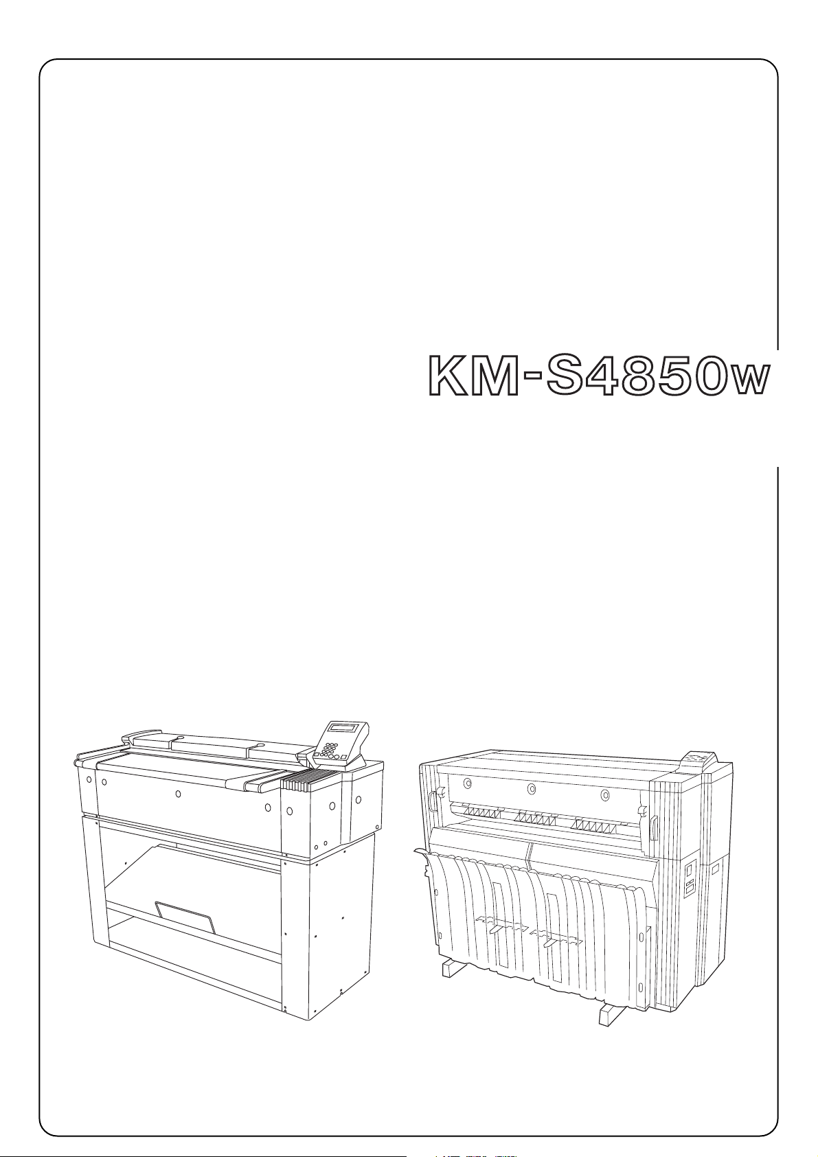
INSTALLATION GUIDE
Page 2

Page 3
A
B
C
F
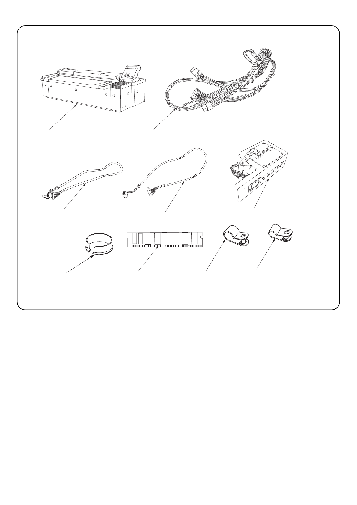
Package Contents
A KM-S4850w ........................................................ 1
B Junction Wiring, Printer Unit ............................... 1
C Junction Wiring, A, Interface PCB ...................... 1
D Junction Wiring, B, Interface PCB ...................... 1
E Scanner Interface PCB ASS’Y ........................... 1
F Open Bushing OCB-100 ..................................... 1
G SD-RAM DIMM 128MB ...................................... 1
H Clamp, GNK-5N .................................................. 2
I Clamp, EMT-3N .................................................. 2
J M4✕6 Binding Screws ........................................ 4
G
D
H
E
I
Important:
When disconnecting the power plug from the main body after
installation, turn off the main switch of the main body and wait
several seconds (more than five seconds) before disconnecting the
plug. Do not disconnect the plug immediately.
NOTE: PROTECT the electronics by taking these precautions
Before touching the main cricuit board and DIMM, touch a water
pipe or other large metal object to discharge yourself of static
electricity. While doing the work, it is recomended that you wear an
antistaic wrist strap.
A: The optional stand is not included in the product
carton.
1
Page 4

1
■Installation Procedure
* Turn the main unit main switch to OFF and unplug the main unit
from the power supply and remove the Ethernet cable before
starting this procedure.
1. Remove 8 screws 1 and M4✕6 Raised Binding Screw2, loosen
the 3 screws at the bottom 1, and remove the rear cover 2.
1
2
3
2. Remove 5 screws 4, and remove the main-PCB cover 5.
4
5
7
6
9
3. From the rear side of the main body, unlock the clamp 6 at the lower
left of the controller cover located at the right side, remove the
connector 7 and the six screws 8, and then remove the controller
cover 9.
8
2
Page 5

@
!
#
4. Lower the two levers 0 at the front of the main unit (pull them out and
down), and pull out the attachment unit !.
0
5. Loosen 2 screws @ and remove the main unit's left rear upper cover
#.
6. Remove 4 screws $, loosen 2 screws $, and remove the main unit's
left rear lower cover %.
@
$
*
$
%
7. Remove 4 screws ^, and remove the scanner interface retainer &.
8. Remove the Network connector *.
^
&
^
3
Page 6

B
9. Put the 9-pin connector side of the Junction Wiring and Printer Unit
B near the main PCB and the 6-pin connector side near the right
side of the controller unit, and then lock the wire saddle ( at seven
locations and lay it down.
9 pin
⁄
)
G
(
6 pin
10. For KM-P4845w (Low Printer)
Insert DIMM G into the memory slot ⁄ of the controller unit until the
hooks ) on both sides are closed.
)
11. Put the connectors of the Junction Wiring A, Interface PCB C and
the Junction Wiring B, Interface PCB D with a binding band ¤ near
the main PCB, and pass the connectors of the other side through the
connection hole ‹ on the main body.
* Pass the relay cable under the sheet metal so that the cable does
not hit the spring.
¤
C
‹
D
4
Page 7

°
12. Connect the modular connector ›, Junction Wiring, Printer Unit
B10-pin connector fi, 6-pin connector fl (on the front side of
Scanner Interface PCB Assembly), Junction Wiring B, Interface PCB
D‡, and Junction Wiring A, Interface PCB C° to the Scanner
Interface PCB Assembly E described in step 11.
‡
›
fi
fl
13. Fit the Scanner Interface PCB Assembly to the main body with four
screws ·.
* When fitting, pass the cord ‚ between the assembly and the main
body so that the cord does not hit the connection portion of the
Scanner Interface PCB Assembly E.
·
·
‚
F
14. Pass the cable to be passed through the connection hole Πat the
rear right of the main body through the Open Bushing, OCB-1000 F,
and fit it to the connection hole Œ.
Œ
5
Page 8

C
H
„
15A. (120 V specifications) Set the shaded area „ of the Junction
Wiring A, Interface PCB C with the clamp, GNK-5N H and the
shaded area ´ of the Junction Wiring B, Interface PCB D with the
clamp, EMT-3N I, and fix them with four binding screws M4 x 6 J.
120 V
D
D
´
I
Ï
I
230 V
C
C
D
´
15B. (230 V specifications) Bind the Shaded area of the Junction
Wiring A, interface PCB C with the CLAMP, GNK-5N H and at the
upper right „ and at the lower left ´, fix it with two binding screws
M4x6 J.
Bind the Shaded area of the Junction Wiring B, interface PCB D
with the CLAMP, EMT-3N I and at the lower right Ï and at the
upper left ˝, fix it with two binding screws M4x6 J.
„
C
C
H
´
˝
D
Ï
16A.(For 120V Specifications) Connect the Junction Wiring A, Interface
PCB C with a binding band to CN5 ˇ, and connect the Junction
Wiring B, Interface PCB D with a binding band to CN4 Á.
* When connecting them, support the IPU PCB with your hand.
ˇ
D
Á
6
Page 9

C
16B. (For 230V Specifications) On the plotter IPU PCB, connect the
connector of the Junction Wiring B, Interface PCB D with a binding
band to the JPEG connector Á, and connect the connector of the
Junction Wiring A, Interface PCB C with a binding band to the
Scanner connector ˇ.
* When connecting them, support the IPU PCB with your hand.
ˇ
D
Á
17. On the Junction Wiring, Printer Unit B, connect the connector ˆ at
the lower part of the main PCB located at the rear of the main body
to the 10-pin connector ¨ and connect the connector ∏ to the 9-pin
connector Ø.
∏
ˆ
Ø
¨
∏
* If the connector ∏ has been already connected on the main body,
disconnect it and then connect it to the Junction.
Ø
18. Reattach the main-PCB cover 5 with 5 screws 4.
5
4
7
Page 10

7
6
9
19. Fit the controller cover with six screws 8, lock the lower left six
clamps 6 on the right controller cover from the rear side of the main
body, and connect the connector 7.
8
20. Reattach the rear cover 3, using 1 M4✕6 Raised Binding Screws
2and the 11 screws 1 that you removed or loosened at Step 1.
@
#
1
1
3
@
2
21. Reattach the main unit's left rear lower cover % with 6 screws $.
22. Reattach the main unit's left rear upper cover # by tightening its 2
screws @.
$
$
%
8
Page 11

!
23. Close the attachment unit ! securely.
24. Connect the Ethernet cable Î, the connector Å and the connector
Í at the left rear of the main body respectively.
Î
Å
Í
25. Execute Sim065, 066 and 067 on operation panel of this product,
and then enter the value of data sheet with this product.
9
Page 12

2001. 11
3B081010A
 Loading...