

Page 1

KM-6330
KM-7530
SERVICE
MANUAL
Published in Feb. ’03
842FA110
Page 2

CAUTION
Danger of explosion if battery is incorrectly replaced. Replace only with the same or equivalent
type recommended by the manufacturer. Dispose of used batteries according to the
manufacturer’s instructions.
CAUTION
Double-pole/neutral fusing.
Page 3

Safety precautions
This booklet provides safety warnings and precautions for our service personnel to ensure the safety of
their customers, their machines as well as themselves during maintenance activities. Service personnel
are advised to read this booklet carefully to familiarize themselves with the warnings and precautions
described here before engaging in maintenance activities.
Page 4
Safety warnings and precautions
Various symbols are used to protect our service personnel and customers from physical danger and
to prevent damage to their property. These symbols are described below:
DANGER: High risk of serious bodily injury or death may result from insufficient attention to or incorrect
compliance with warning messages using this symbol.
WARNING:Serious bodily injury or death may result from insufficient attention to or incorrect compliance
with warning messages using this symbol.
CAUTION:Bodily injury or damage to property may result from insufficient attention to or incorrect
compliance with warning messages using this symbol.
Symbols
The triangle ( ) symbol indicates a warning including danger and caution. The specific point
of attention is shown inside the symbol.
General warning.
Warning of risk of electric shock.
Warning of high temperature.
indicates a prohibited action. The specific prohibition is shown inside the symbol.
General prohibited action.
Disassembly prohibited.
indicates that action is required. The specific action required is shown inside the symbol.
General action required.
Remove the power plug from the wall outlet.
Always ground the copier.
Page 5

1. Installation Precautions
WARNING
• Do not use a power supply with a voltage other than that specified. Avoid multiple connections to
one outlet: they may cause fire or electric shock. When using an extension cable, always check
that it is adequate for the rated current. ............................................................................................
• Connect the ground wire to a suitable grounding point. Not grounding the copier may cause fire or
electric shock. Connecting the earth wire to an object not approved for the purpose may cause
explosion or electric shock. Never connect the ground cable to any of the following: gas pipes,
lightning rods, ground cables for telephone lines and water pipes or faucets not approved by the
proper authorities. .............................................................................................................................
CAUTION:
• Do not place the copier on an infirm or angled surface: the copier may tip over, causing injury. .....
• Do not install the copier in a humid or dusty place. This may cause fire or electric shock. ..............
• Do not install the copier near a radiator, heater, other heat source or near flammable material.
This may cause fire. ..........................................................................................................................
• Allow sufficient space around the copier to allow the ventilation grills to keep the machine as cool
as possible. Insufficient ventilation may cause heat buildup and poor copying performance. ..........
• Always handle the machine by the correct locations when moving it. ..............................................
• Always use anti-toppling and locking devices on copiers so equipped. Failure to do this may
cause the copier to move unexpectedly or topple, leading to injury..................................................
• Avoid inhaling toner or developer excessively. Protect the eyes. If toner or developer is
accidentally ingested, drink a lot of water to dilute it in the stomach and obtain medical attention
immediately. If it gets into the eyes, rinse immediately with copious amounts of water and obtain
medical attention. ..............................................................................................................................
• Advice customers that they must always follow the safety warnings and precautions in the copier’s
instruction handbook. ........................................................................................................................
Page 6
2. Precautions for Maintenance
WARNING
• Always remove the power plug from the wall outlet before starting machine disassembly...............
• Always follow the procedures for maintenance described in the service manual and other related
brochures. .........................................................................................................................................
• Under no circumstances attempt to bypass or disable safety features including safety
mechanisms and protective circuits. .................................................................................................
• Always use parts having the correct specifications...........................................................................
• Always use the thermostat or thermal fuse specified in the service manual or other related
brochure when replacing them. Using a piece of wire, for example, could lead to fire or other
serious accident. ...............................................................................................................................
• When the service manual or other serious brochure specifies a distance or gap for installation of a
part, always use the correct scale and measure carefully. ...............................................................
• Always check that the copier is correctly connected to an outlet with a ground connection. ............
• Check that the power cable covering is free of damage. Check that the power plug is dust-free. If
it is dirty, clean it to remove the risk of fire or electric shock. ............................................................
• Never attempt to disassemble the optical unit in machines using lasers. Leaking laser light may
damage eyesight. ..............................................................................................................................
• Handle the charger sections with care. They are charged to high potentials and may cause
electric shock if handled improperly. .................................................................................................
CAUTION
• Wear safe clothing. If wearing loose clothing or accessories such as ties, make sure they are
safely secured so they will not be caught in rotating sections...........................................................
• Use utmost caution when working on a powered machine. Keep away from chains and belts. .......
• Handle the fixing section with care to avoid burns as it can be extremely hot. .................................
• Check that the fixing unit thermistor, heat and press rollers are clean. Dirt on them can cause
abnormally high temperatures...........................................................................................................
• Do not remove the ozone filter, if any, from the copier except for routine replacement....................
Page 7
• Do not pull on the AC power cord or connector wires on high-voltage components when removing
them; always hold the plug itself. ......................................................................................................
• Do not route the power cable where it may be stood on or trapped. If necessary, protect it with a
cable cover or other appropriate item. ..............................................................................................
• Treat the ends of the wire carefully when installing a new charger wire to avoid electric leaks........
• Remove toner completely from electronic components. ...................................................................
• Run wire harnesses carefully so that wires will not be trapped or damaged. ...................................
• After maintenance, always check that all the parts, screws, connectors and wires that were
removed, have been refitted correctly. Special attention should be paid to any forgotten
connector, trapped wire and missing screws. ..................................................................................
• Check that all the caution labels that should be present on the machine according to the
instruction handbook are clean and not peeling. Replace with new ones if necessary. ...................
• Handle greases and solvents with care by following the instructions below: ....................................
· Use only a small amount of solvent at a time, being careful not to spill. Wipe spills off completely.
· Ventilate the room well while using grease or solvents.
· Allow applied solvents to evaporate completely before refitting the covers or turning the main
switch on.
· Always wash hands afterwards.
• Never dispose of toner or toner bottles in fire. Toner may cause sparks when exposed directly to
fire in a furnace, etc...........................................................................................................................
• Should smoke be seen coming from the copier, remove the power plug from the wall outlet
immediately. ......................................................................................................................................
3. Miscellaneous
WARNING
• Never attempt to heat the drum or expose it to any organic solvents such as alcohol, other than
the specified refiner; it may generate toxic gas. ................................................................................
Page 8

CONTENTS
1-1 Specifications
1-1-1 Specifications ....................................................................................................................................... 1-1-1
1-1-2 Parts names and their functions ........................................................................................................... 1-1-3
(1) Copier ............................................................................................................................................. 1-1-3
(2) Operation panel .............................................................................................................................. 1-1-4
1-1-3 Machine cross section .......................................................................................................................... 1-1-5
1-1-4 Drive system ........................................................................................................................................ 1-1-6
(1) Drive system 1 (optical section) ...................................................................................................... 1-1-6
(2) Drive system 2 (paper feed motor drive train) ................................................................................ 1-1-7
(3) Drive system 3 (image forming motor drive train) ........................................................................... 1-1-8
(4) Drive system 4 (drive motor drive train) .......................................................................................... 1-1-9
(5) Drive system 5 (large paper deck) ................................................................................................ 1-1-10
(6) Drive system 6 (duplex section) ................................................................................................... 1-1-11
(7) Drive system 7 (SRDF) ................................................................................................................. 1-1-12
1-2 Handling Precautions
1-2-1 Drum .................................................................................................................................................... 1-2-1
1-2-2 Developer and toner ............................................................................................................................. 1-2-1
1-2-3 Installation environment ....................................................................................................................... 1-2-1
2CJ/2FA-1
1-3 Installation
1-3-1 Unpacking and installation ................................................................................................................... 1-3-1
(1) Installation procedure ..................................................................................................................... 1-3-1
1-3-2 Setting initial copy modes .................................................................................................................. 1-3-16
1-3-3 Installing the key counter (option) ...................................................................................................... 1-3-17
1-3-4 Installing the cassette heater (option) ................................................................................................ 1-3-19
1-3-5 Installing the multi finisher (option) ..................................................................................................... 1-3-20
1-3-6 Installing the side deck (option) .......................................................................................................... 1-3-30
1-3-7 Installing the printing system (option) ................................................................................................. 1-3-34
1-3-8 Installing the scanning system (option) .............................................................................................. 1-3-36
1-3-9 Installing the tandem kit (option) ........................................................................................................ 1-3-38
1-4 Maintenance Mode
1-4-1 Copier management ............................................................................................................................. 1-4-1
(1) Using the copier management mode .............................................................................................. 1-4-1
(2) Setting department management items .......................................................................................... 1-4-2
(3) Weekly timer ................................................................................................................................... 1-4-2
(4) Copy default ................................................................................................................................... 1-4-3
(5) Machine default .............................................................................................................................. 1-4-5
(6) Bypass Setting ................................................................................................................................ 1-4-6
(7) Document management default setting .......................................................................................... 1-4-6
(8) Hard disk management .................................................................................................................. 1-4-7
(9) Report ............................................................................................................................................. 1-4-7
(10) Language ........................................................................................................................................ 1-4-7
1-4-2 Maintenance mode ............................................................................................................................... 1-4-8
(1) Executing a maintenance item ....................................................................................................... 1-4-8
(2) Maintenance mode item list ............................................................................................................ 1-4-9
(3) Contents of maintenance mode items .......................................................................................... 1-4-13
1-1-1
1-5 Troubleshooting
1-5-1 Paper misfeed detection ...................................................................................................................... 1-5-1
(1) Paper misfeed indication ................................................................................................................ 1-5-1
(2) Paper misfeed detection conditions ................................................................................................ 1-5-2
(3) Paper misfeeds ............................................................................................................................... 1-5-9
1-5-2 Self-diagnosis ..................................................................................................................................... 1-5-19
(1) Self-diagnostic function ................................................................................................................ 1-5-19
(2) Self-diagnostic codes ................................................................................................................... 1-5-20
Page 9

2CJ/2FA
1-5-3 Image formation problems ................................................................................................................. 1-5-36
(1) No image appears (entirely white). ............................................................................................... 1-5-38
(2) No image appears (entirely black). ............................................................................................... 1-5-38
(3) Image is too light. ......................................................................................................................... 1-5-39
(4) Background is visible. ................................................................................................................... 1-5-39
(5) A white line appears longitudinally. .............................................................................................. 1-5-39
(6) A black line appears longitudinally. .............................................................................................. 1-5-40
(7) A black line appears laterally. ....................................................................................................... 1-5-40
(8) One side of the copy image is darker than the other. ................................................................... 1-5-40
(9) Black dots appear on the image. .................................................................................................. 1-5-41
(10) Image is blurred. ........................................................................................................................... 1-5-41
(11) The leading edge of the image is consistently misaligned with the original. ................................ 1-5-41
(12) The leading edge of the image is sporadically misaligned with the original. ................................ 1-5-42
(13) Paper creases. ............................................................................................................................. 1-5-42
(14) Offset occurs. ............................................................................................................................... 1-5-42
(15) Image is partly missing. ................................................................................................................ 1-5-43
(16) Fixing is poor. ............................................................................................................................... 1-5-43
(17) Image is out of focus. ................................................................................................................... 1-5-43
(18) Image center does not align with the original center. ................................................................... 1-5-43
(19) Image is not square. ..................................................................................................................... 1-5-44
(20) Image contrast is low (carrier scattering) ...................................................................................... 1-5-44
(21) When the large paper deck is used, the center of the original image
and that of the copy image do not align. ....................................................................................... 1-5-44
(22) There is a regular error between the centers of the original and copy image
when the SRDF is used. ............................................................................................................... 1-5-45
(23) There is a regular error between the leading edges of
the original and copy image when the SRDF is used. .................................................................. 1-5-45
1-5-4 Electrical problems ............................................................................................................................. 1-5-46
• Copier
(1) The machine does not operate when the main switch is turned on. ............................................. 1-5-46
(2) The image forming motor does not operate (C2000). .................................................................. 1-5-46
(3) The drive motor does not operate (C2550). ................................................................................. 1-5-46
(4) Paper feed motor does not operate (C2500). ............................................................................... 1-5-46
(5) The scanner motor does not operate. .......................................................................................... 1-5-47
(6) The duplex fan motor does not operate. ....................................................................................... 1-5-47
(7) The optical section motor does not operate. ................................................................................ 1-5-47
(8) The cooling fan motor does not operate. ...................................................................................... 1-5-47
(9) The fixing unit fan motor does not operate. .................................................................................. 1-5-47
(10) LSU fan motor 1 does not operate. .............................................................................................. 1-5-48
(11) LSU fan motor 2 does not operate. .............................................................................................. 1-5-48
(12) The main charger fan motor does not operate. ............................................................................ 1-5-48
(13) The eject fan motor does not operate. .......................................................................................... 1-5-48
(14) The upper lift motor does not operate (C1030). ........................................................................... 1-5-48
(15) The lower lift motor does not operate (C1040). ............................................................................ 1-5-49
(16) The large paper deck right lift motor does not operate (C1050). .................................................. 1-5-49
(17) The large paper deck left lift motor does not operate (C1060). .................................................... 1-5-49
(18) Blow fan motor 1 does not operate. .............................................................................................. 1-5-49
(19) Blow fan motor 2 does not operate. .............................................................................................. 1-5-49
(20) The toner feed motor does not operate. ....................................................................................... 1-5-49
(21) The main charger cleaning motor does not operate. .................................................................... 1-5-50
(22) The toner agitation motor does not operate. ................................................................................ 1-5-50
(23) The registration clutch does not operate. ..................................................................................... 1-5-50
(24) Feed clutch 1 does not operate. ................................................................................................... 1-5-50
(25) Feed clutch 2 does not operate. ................................................................................................... 1-5-50
(26) Feed clutch 3 does not operate. ................................................................................................... 1-5-51
(27) Feed clutch 4 does not operate. ................................................................................................... 1-5-51
(28) Feed clutch 5 does not operate. ................................................................................................... 1-5-51
(29) The upper paper feed clutch does not operate. ............................................................................ 1-5-51
1-1-2
Page 10

2CJ/2FA
(30) The lower paper feed clutch does not operate. ............................................................................ 1-5-51
(31) The bypass lift clutch does not operate. ....................................................................................... 1-5-51
(32) The bypass paper feed clutch does not operate. ......................................................................... 1-5-52
(33) The duplex forwarding clutch does not operate. ........................................................................... 1-5-52
(34) The duplex reversing clutch does not operate. ............................................................................. 1-5-52
(35) The large paper deck conveying clutch does not operate. ........................................................... 1-5-52
(36) Large paper deck paper feed clutch 1 does not operate. ............................................................. 1-5-52
(37) Large paper deck paper feed clutch 2 does not operate. ............................................................. 1-5-53
(38) The transfer charger belt release clutch does not operate. .......................................................... 1-5-53
(39) The duplex eject switching solenoid does not operate. ................................................................ 1-5-53
(40) The duplex pressure release solenoid does not operate. ............................................................. 1-5-53
(41) The feedshift solenoid does not operate. ..................................................................................... 1-5-53
(42) The fixing web solenoid does not operate. ................................................................................... 1-5-54
(43) The cleaning lamp does not turn on. ............................................................................................ 1-5-54
(44) The exposure lamp does not turn on. ........................................................................................... 1-5-54
(45) The exposure lamp does not turn off. ........................................................................................... 1-5-54
(46) Fixing heater M or S does not turn on (C6000). ........................................................................... 1-5-54
(47) Fixing heater M or S does not turn off. ......................................................................................... 1-5-54
(48) Main charging is not performed (C5100). ..................................................................................... 1-5-55
(49) Transfer charging is not performed (C5110). ............................................................................... 1-5-55
(50) No developing bias is output. ....................................................................................................... 1-5-55
(51) The original size is not detected. .................................................................................................. 1-5-55
(52) The original size is not detected correctly. ................................................................................... 1-5-55
(53) The touch panel keys do not work. ............................................................................................... 1-5-55
(54) The message requesting paper to be loaded is shown when paper is present
in the large paper deck. ................................................................................................................ 1-5-56
(55) The message requesting paper to be loaded is shown when paper is present
in the upper cassette. ................................................................................................................... 1-5-56
(56) The message requesting paper to be loaded is shown when paper is present
in the lower cassette. .................................................................................................................... 1-5-56
(57) The message requesting paper to be loaded is shown when paper is present
on the bypass table. ..................................................................................................................... 1-5-56
(58) The size of paper in the upper cassette is not displayed correctly. .............................................. 1-5-56
(59) The size of paper in the lower cassette is not displayed correctly. ............................................... 1-5-57
(60) The size of paper on the bypass table is not displayed correctly. ................................................ 1-5-57
(61) A paper jam in the paper feed, paper conveying or fixing section is indicated
on the touch panel immediately after the main switch is turned on. ............................................. 1-5-57
(62) The message requesting covers to be closed is displayed when the front, upper right,
lower right and eject covers are closed. ....................................................................................... 1-5-58
(63) Others. .......................................................................................................................................... 1-5-58
• DF
(1) The original feed motor does not operate. .................................................................................... 1-5-59
(2) The original conveying motor does not operate. .......................................................................... 1-5-59
(3) The original feed solenoid does not operate. ............................................................................... 1-5-59
(4) The switchback feedshift solenoid does not operate. ................................................................... 1-5-59
(5) The eject feedshift solenoid does not operate. ............................................................................. 1-5-59
(6) The switchback pressure solenoid does not operate. .................................................................. 1-5-59
(7) The original feed clutch does not operate. ................................................................................... 1-5-60
(8) A message indicating cover open is displayed when the SRDF is closed correctly. .................... 1-5-60
(9) An original jams when the main switch is turned on. .................................................................... 1-5-60
1-5-5 Mechanical problems ......................................................................................................................... 1-5-61
• Copier
(1) No primary paper feed. ................................................................................................................. 1-5-61
(2) No secondary paper feed. ............................................................................................................ 1-5-61
(3) Skewed paper feed. ...................................................................................................................... 1-5-61
(4) The scanner does not travel. ........................................................................................................ 1-5-61
(5) Multiple sheets of paper are fed at one time.................................................................................. 1-5-61
(6) No refeed. ..................................................................................................................................... 1-5-61
1-1-3
Page 11

2CJ/2FA
(7) Paper jams. .................................................................................................................................. 1-5-61
(8) Toner drops on the paper conveying path. ................................................................................... 1-5-62
(9) Abnormal noise is heard. .............................................................................................................. 1-5-62
• DF
(1) No primary original feed. .............................................................................................................. 1-5-63
(2) No secondary original feed. .......................................................................................................... 1-5-63
(3) Originals jam. ................................................................................................................................ 1-5-63
1-6 Assembly and Disassembly
1-6-1 Precautions for assembly and disassembly ......................................................................................... 1-6-1
(1) Precautions ..................................................................................................................................... 1-6-1
(2) Running a maintenance item .......................................................................................................... 1-6-2
1-6-2 Paper feed section ............................................................................................................................... 1-6-3
(1) Detaching and refitting the forwarding, upper and lower paper feed pulleys .................................. 1-6-3
(2) Detaching and refitting the bypass forwarding roller, bypass upper and
lower paper feed pulleys ................................................................................................................. 1-6-6
(2-1) Detaching the bypass paper feed unit ................................................................................... 1-6-6
(2-2) Detaching the bypass forwarding roller ................................................................................. 1-6-7
(2-3) Detaching the bypass upper paper feed pulley ..................................................................... 1-6-7
(2-4) Detaching the bypass lower paper feed pulley ...................................................................... 1-6-8
(3) Cleaning the paper feed belts ......................................................................................................... 1-6-9
(4) Detaching and refitting the deck paper feed roller and deck paper conveying roller .................... 1-6-11
(5) Detaching and refitting the upper and lower paper width switches
(For inch models only.) ................................................................................................................. 1-6-12
(6) Detaching and refitting the bypass paper width switch ................................................................. 1-6-14
(7) Adjusting the center registration ................................................................................................... 1-6-15
(7-1) Adjusting the position of the rack adjuster ........................................................................... 1-6-15
(7-2) Adjusting the position of the center adjuster ........................................................................ 1-6-16
(8) Adjustment after roller and clutch replacement ............................................................................ 1-6-17
(8-1) Adjusting the leading edge registration ............................................................................... 1-6-17
(8-2) Adjusting the leading edge registration for duplex switchback copying ............................... 1-6-18
(8-3) Adjusting the center line of image printing ........................................................................... 1-6-19
(8-4) Adjusting the margins for printing ........................................................................................ 1-6-20
(8-5) Adjusting the amount of slack in the paper at the registration roller for drawer,
bypass and duplex feeds ..................................................................................................... 1-6-21
(8-6) Adjusting the amount of slack in the paper at the vertical conveying .................................. 1-6-22
(9) Detaching and refitting the upper registration roller ...................................................................... 1-6-23
(10) Detaching and refitting the lower registration roller ...................................................................... 1-6-25
1-6-3 Main charging section ........................................................................................................................ 1-6-26
(1) Replacing the charger wire and charger grid assembly ............................................................... 1-6-26
(2) Replacing the grid wire cleaning pad and charger wire cleaning pad .......................................... 1-6-28
1-6-4 Optical section .................................................................................................................................... 1-6-29
(1) Detaching and refitting the exposure lamp ................................................................................... 1-6-29
(2) Detaching and refitting the scanner wires .................................................................................... 1-6-30
(2-1) Detaching the scanner wires ............................................................................................... 1-6-30
(2-2) Refitting the scanner wires .................................................................................................. 1-6-31
(3) Replacing the laser scanner unit .................................................................................................. 1-6-33
(4) Replacing the ISU (reference) ...................................................................................................... 1-6-34
(5) Adjusting the longitudinal squareness (reference) ....................................................................... 1-6-35
(6) Adjusting scanner image lateral squareness (reference) ............................................................. 1-6-36
(6-1) Adjusting the position of the laser scanner unit ................................................................... 1-6-36
(6-2) Adjusting the position of the ISU ......................................................................................... 1-6-38
(7) Adjusting magnification of the scanner in the main scanning direction ........................................ 1-6-39
(8) Adjusting magnification of the scanner in the auxiliary scanning direction ................................... 1-6-40
(9) Adjusting the scanner center line ................................................................................................. 1-6-41
(10) Adjusting the scanner leading edge registration ........................................................................... 1-6-42
(11) Adjusting the margins for scanning an original on the contact glass ............................................ 1-6-43
1-6-5 Drum section ...................................................................................................................................... 1-6-44
(1) Detaching and refitting the drum and drum heater ....................................................................... 1-6-44
(2) Detaching and refitting the front and rear drum electrode wires ................................................... 1-6-46
(3) Detaching and refitting the drum heater electrodes A and B ........................................................ 1-6-48
1-1-4
Page 12

2CJ/2FA-1
1-6-6 Developing section ............................................................................................................................. 1-6-49
(1) Adjusting the position of the magnetic brush (developing roller) (reference) ............................... 1-6-49
(2) Checking the position of the doctor blade (reference) .................................................................. 1-6-50
(3) Detaching and refitting the developing filter and the upper developing seal ................................ 1-6-51
(4) Detaching and refitting the lower developing shaft and developing blade assembly ................... 1-6-52
1-6-7 Transfer section ................................................................................................................................. 1-6-53
(1) Detaching and refitting the transfer charger belt .......................................................................... 1-6-53
(2) Detaching and refitting the transfer roller ..................................................................................... 1-6-54
(3) Detaching and refitting the belt cleaning brush ............................................................................ 1-6-55
1-6-8 Cleaning section ................................................................................................................................. 1-6-56
(1) Detaching and refitting the cleaning blade ................................................................................... 1-6-56
(2) Detaching and refitting the cleaning brush ................................................................................... 1-6-58
(3) Detaching and refitting the cleaning brush mount ........................................................................ 1-6-59
(4) Detaching and refitting the separation claw assembly ................................................................. 1-6-60
1-6-9 Fixing section ..................................................................................................................................... 1-6-61
(1) Detaching and refitting the fixing unit thermostat ......................................................................... 1-6-61
(2) Detaching and refitting the cleaning felt ....................................................................................... 1-6-62
(3) Detaching and refitting the fixing heaters M and S ....................................................................... 1-6-63
(4) Detaching and refitting the fixing unit thermistor .......................................................................... 1-6-65
(5) Detaching and refitting the lower cleaning roller ........................................................................... 1-6-66
(6) Detaching and refitting the heat roller and press roller ................................................................. 1-6-67
(7) Detaching and refitting the heat roller separation claw ................................................................. 1-6-68
(8) Detaching and refitting the press roller separation claw ............................................................... 1-6-69
1-6-10 Duplex section .................................................................................................................................... 1-6-70
(1) Cleaning the duplex switchback rollers ........................................................................................ 1-6-70
(2) Adjusting the position of the duplex eject switching solenoid ....................................................... 1-6-71
(3) Setting the switchback drive ......................................................................................................... 1-6-72
1-6-11 SRDF section ..................................................................................................................................... 1-6-73
(1) Detaching and refitting the DF forwarding pulley and the DF feed pulleys ................................... 1-6-73
(2) Detaching and refitting the DF separation pulley .......................................................................... 1-6-74
(3) Adjusting the DF magnification ..................................................................................................... 1-6-78
(4) Adjusting the DF center line ......................................................................................................... 1-6-79
(5) Adjusting the scanning start position when the DF is used .......................................................... 1-6-80
(5-1) Adjusting the DF leading edge registration .......................................................................... 1-6-80
(5-2) Adjusting the DF traling edge registration ........................................................................... 1-6-81
(6) Adjusting the margins for scanning the original from the DF ........................................................ 1-6-82
1-6-12 Others ................................................................................................................................................ 1-6-83
(1) Detaching and refitting the drum grounding plate spring .............................................................. 1-6-83
(2) Detaching and refitting the front cleaning seal ............................................................................. 1-6-84
1-7 Requirements on PCB Replacement
1-7-1 Upgrading the firmware on the main PCB ............................................................................................ 1-7-1
1-7-2 Adjustment-free variable resisters (VR) ............................................................................................... 1-7-2
2-1 Mechanical construction
2-1-1 Paper feed section ............................................................................................................................... 2-1-1
(1) Paper feed from the cassettes ........................................................................................................ 2-1-1
(2) Paper feed from the large paper deck ............................................................................................ 2-1-5
(2-1) Right cassette paper feed ...................................................................................................... 2-1-6
(2-2) Left cassette paper feed ........................................................................................................ 2-1-8
(2-3) Raising and lowering the lifts ................................................................................................. 2-1-9
(2-4) Detecting the paper level ..................................................................................................... 2-1-10
(3) Paper feed from the bypass table ................................................................................................. 2-1-11
2-1-2 Main charging section ........................................................................................................................
2-1-3 Optical section ....................................................................................................................................
(1) Original scanning ..........................................................................................................................
(2) Image printing ...............................................................................................................................
1-1-5
2-1-14
2-1-17
2-1-18
2-1-19
Page 13

2CJ/2FA-1
2-1-4 Developing section .............................................................................................................................
(1) Formation of magnetic brush ........................................................................................................
(2) Toner density control ....................................................................................................................
(2-1) Toner empty detection by the toner sensor .........................................................................
(2-2) Controling the toner feed motor and toner agitation motor ..................................................
(2-3) Toner empty detection by the toner level sensor .................................................................
(2-4) Toner control level absolute humidity correction .................................................................
2-1-5 Transfer and conveying sections .......................................................................................................
2-1-6 Cleaning section .................................................................................................................................
2-1-7 Charge erasing section ......................................................................................................................
2-1-8 Fixing section .....................................................................................................................................
2-1-9 Feedshift and eject sections ...............................................................................................................
2-1-10 Duplex section ....................................................................................................................................
2-1-11 SRDF .................................................................................................................................................
(1) Original feed section .....................................................................................................................
(1-1) Original feed timing ..............................................................................................................
(2) Original switchback section ..........................................................................................................
(2-1) Operation of original switchback ..........................................................................................
(3) Original conveying section ............................................................................................................
(3-1) Original switchback/conveying timing ..................................................................................
2-2 Electrical Parts Layout
2-2-1 Electrical parts layout ........................................................................................................................... 2-2-1
(1) PCBs .............................................................................................................................................. 2-2-1
(2) Switches and sensors ..................................................................................................................... 2-2-2
(3) Motors ............................................................................................................................................. 2-2-4
(4) Clutches and solenoids .................................................................................................................. 2-2-5
(5) Other electrical components ........................................................................................................... 2-2-6
(6) SRDF switches and sensors .......................................................................................................... 2-2-7
(7) SRDF motors .................................................................................................................................. 2-2-8
(8) SRDF clutches and solenoids ........................................................................................................ 2-2-9
2-1-21
2-1-22
2-1-24
2-1-24
2-1-25
2-1-25
2-1-25
2-1-26
2-1-29
2-1-30
2-1-31
2-1-34
2-1-36
2-1-39
2-1-39
2-1-40
2-1-41
2-1-42
2-1-43
2-1-44
2-3 Operation of the PCBs
2-3-1 Power source PCB ............................................................................................................................... 2-3-1
2-3-2 Main PCB ............................................................................................................................................. 2-3-6
2-3-3 Engine PCB ........................................................................................................................................ 2-3-11
2-3-4 Scanner motor PCB ...........................................................................................................................
2-3-5 CCD PCB ...........................................................................................................................................
2-4 Appendixes
Timing chart No. 1 .......................................................................................................................................... 2-4-1
Timing chart No. 2 .......................................................................................................................................... 2-4-2
Timing chart No. 3 .......................................................................................................................................... 2-4-3
Timing chart No. 4 .......................................................................................................................................... 2-4-4
Timing chart No. 5 .......................................................................................................................................... 2-4-5
Timing chart No. 6 .......................................................................................................................................... 2-4-6
Timing chart No. 7 .......................................................................................................................................... 2-4-7
Timing chart No. 8 .......................................................................................................................................... 2-4-8
Timing chart No. 9 .......................................................................................................................................... 2-4-9
Timing chart No. 10 ...................................................................................................................................... 2-4-10
Chart of image adjustment procedures ........................................................................................................ 2-4-11
Maintenance parts list................................................................................................................................... 2-4-14
Periodic maintenance procedures ................................................................................................................ 2-4-16
Optional devices supplied parts list .............................................................................................................. 2-4-21
List of error codes ......................................................................................................................................... 2-4-22
Functions and settings combination chart .................................................................................................... 2-4-25
General wiring diagram (63 cpm) ................................................................................................................. 2-4-26
General wiring diagram (75 cpm) ................................................................................................................. 2-4-27
1-1-6
2-3-19
2-3-22
Page 14

1-1-1 Specifications
Copier
Type ............................................... Console
Copying system.............................. Indirect electrostatic system
Originals ......................................... Sheets and books
Maximum size: A3/11" × 17"
Original feed system ...................... Fixed
Copy paper .................................... Cassette: Plain paper (60 – 80 g/m
Duplex unit: Plain paper (64 – 105 g/m
Bypass table: Plain paper (45 – 200 g/m
Special paper:
Transparencies, tracing paper, colored paper and envelopes (only when used as a
printer)
Note: Use the bypass table for special paper.
Copying sizes ................................. Maximum: A3/11" × 17"
1
Minimum: A6R/5
/2" × 81/2"
During duplex copying
Maximum: A3/11" × 17"
1
Minimum: A5R/5
/2" × 81/2"
Magnification ratios ........................ Manual mode: 25 – 400%, 1% increments
Auto copy mode: Fixed ratios
Metric
1:1, 1:4.00/1:2.00/1:1.41/1:1.06/1:0.75/1:0.70/1:0.50/1:0.25
Inch
1:1, 1:4.00/1:2.00/1:1.29/1:1.21/1:0.78/1:0.64/1:0.50/1:0.25
100% magnification ........................ Copier: ±0.8%
SRDF: ±1.5%
Enlargement/reduction ................... Copier: ±1.0%
SRDF: ±1.5%
Copy speed .................................... At 100% magnification in memory copy mode:
• 63 cpm
A4/11" × 81/2": 63 copies/min.
1
A4R/8
/2" × 11": 44 copies/min.
A3/11" × 17": 32 copies/min.
1
B4 (257 × 364 mm)/8
/2" × 14": 38 copies/min.
B5: 63 copies/min.
B5R: 50 copies/min.
When the SRDF is used (at 100% magnification):
A4/11" × 81/2": 63 copies/min.
• 75 cpm
×
A4/11"
A4R/8
A3/11"
B4 (257
81/2": 75 copies/min.
1
/2"
×
11": 52 copies/min.
×
17": 38 copies/min.
×
364 mm)/81/2"
×
B5: 75 copies/min.
B5R: 60 copies/min.
When the SRDF is used (at 100% magnification):
A4/11"
×
81/2": 75 copies/min.
First copy time ................................
3.6 s (63 cpm)/3.2 s (75 cpm)
manual copy density control)
Warm-up time................................. 360 s or less (room temperature 20°C/68°F, 65%RH)
With preheat, switchable between 90 s and 30 s (room temperature 20°C/68°F,
65%RH)
Paper feed system ......................... Automatic feed
Capacity:
Cassette (two cassettes): 500 sheets
Large paper deck: 3000 sheets
Manual feed
Capacity:
Bypass: 100 sheets
Multiple copying ............................. 1 – 999 copies
Photoconductor .............................. a-Si (film thickness 30 µm, drum diameter 84 mm)
2
)
2
)
2
)
14": 45 copies/min.
(A4/11" × 81/2", 100% magnification, upper cassette,
2CJ/2FA-1
1-1-1
Page 15

2CJ/2FA-1
Charging system ............................ Double positive corona charging, 900 µA
Recording system .......................... Semiconductor laser
Developing system ......................... Dry, reverse developing (double magnet roller)
Developer: 2-component, ferrite carrier and N32T black toner
Density control: Developer density detection
Toner replenishing: Automatic from a toner hopper
Transfer system ............................. Transfer belt, approximately 1.2 to 1.3 kV (rated current: 50 µA)
Separation system ......................... Transfer belt and separation claws
Fixing system ................................. Heat roller
Heat source: Halogen heaters
63 cpm: main 970 W for 120 V/1350 W for 230/240 V models,
sub 270 W for 120 V models/380 W for 230/240 V models
75 cpm: main 1025 W for 120 V/1350 W for 230/240 V models,
sub 270 W for 120 V models/380 W for 230/240 V models
Control temperature: 190°C/374°F (at normal ambient temperature)
Abnormally high temperature protection devices: 180°C/356°F thermostats
Fixing pressure:
60 N (63 cpm)
160 N for 120 V models/154 N for 230/240 V models (75 cpm)
Charge erasing system .................. Exposure by cleaning lamp
Cleaning system............................. Blade and fur brush
Scanning system ............................ Flat bed scanning by CCD image sensor
Bitmap memory .............................. 128 MB (standard)
Image storage memory .................. 20 GB (standard)
Resolution ...................................... 600 × 600 dpi
Light source ................................... Inert gas lamp (24 W)
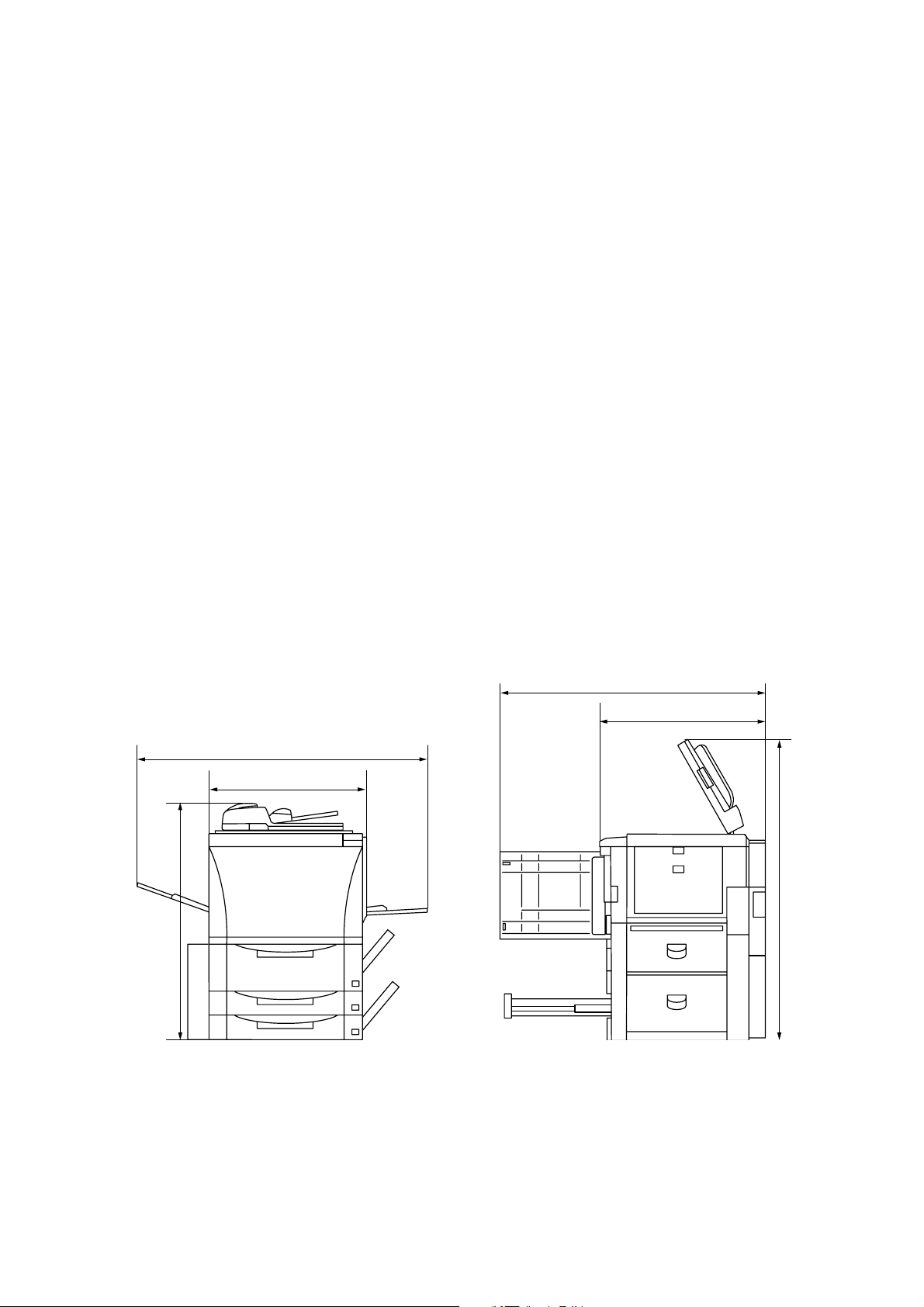
Dimensions ....................................
685 (W)
26
15
/16" (W)
×
800 (D)
×
311/2" (D)
×
1181 (H) mm
×
461/2" (H)
Weight ............................................200 kg/440 lbs
Floor requirements .........................
1390 mm (W)
3
/4" (W)
54
×
×
800 (D) mm
311/2" (D)
Functions........................................ Auto paper selection mode, Image quality selection, Auto magnification selection
mode, Zoom mode, Preset zoom mode, XY zoom mode, 2-sided copy modes, Page
separation/Split copy modes, Margin mode, Centering/Image shift mode, Memo
mode, Border erase modes, Combine/Merge Copy modes, Print page numbers
mode, Form overlay mode, Booklet/Stitching mode, Book to Booklet mode, Sort/
Finished mode, Auto rotation function, Auto Selection/Filing mode, Cover mode,
Transparency + backing sheet mode, Invert mode, Mirror image mode, Proof mode,
Repeat copy mode, Batch scanning mode, Eco print mode, Program function, Job
build mode, Form registration, Shared data box, Synergy print boxes, Copy
management mode, Weekly timer function, Language selection function
Power source .................................
63 cpm:
120 V AC, 60 Hz, 13A/220 – 240 V AC, 50 Hz, 4.9 A (ave.)
75 cpm: 120 V AC, 60 Hz, 15A/220 – 240 V AC, 50 Hz, 7.0 A (ave.)
Power consumption........................
63 cpm:
1920 W (max.) for 120 V models/2400 W (max.) for 220 – 240 V models
75 cpm: 1920 W (max.) for 120 V models/1920 W (max.) for 220 – 240 V models
Options ........................................... Side deck, finisher, key counter, print/scan system and tandem copy kit.
Document processor
Original feed system ...................... Automatic feed
Originals ......................................... Sheets
Original weights ............................. Single-sided original mode: 35 – 160 g/m
Double-sided original mode: 50 – 120 g/m
2
2
Original paper ................................ Plain paper, thermal paper, art paper and colored paper
1
Original sizes.................................. A3 – A5R, folio/11" × 17" – 5
No. of originals ............................... Up to 70 sheets (A3, B4, folio, 11" × 17", 8
Up to 100 sheets (up to A4/11" × 8
/2" × 81/2"
1
/2")
1
/2" × 14")
Up to 30 sheets in the auto selection mode
Art or thermal paper must be fed individually.
Power source ................................. Electrically connected to the copier
1-1-2
Page 16
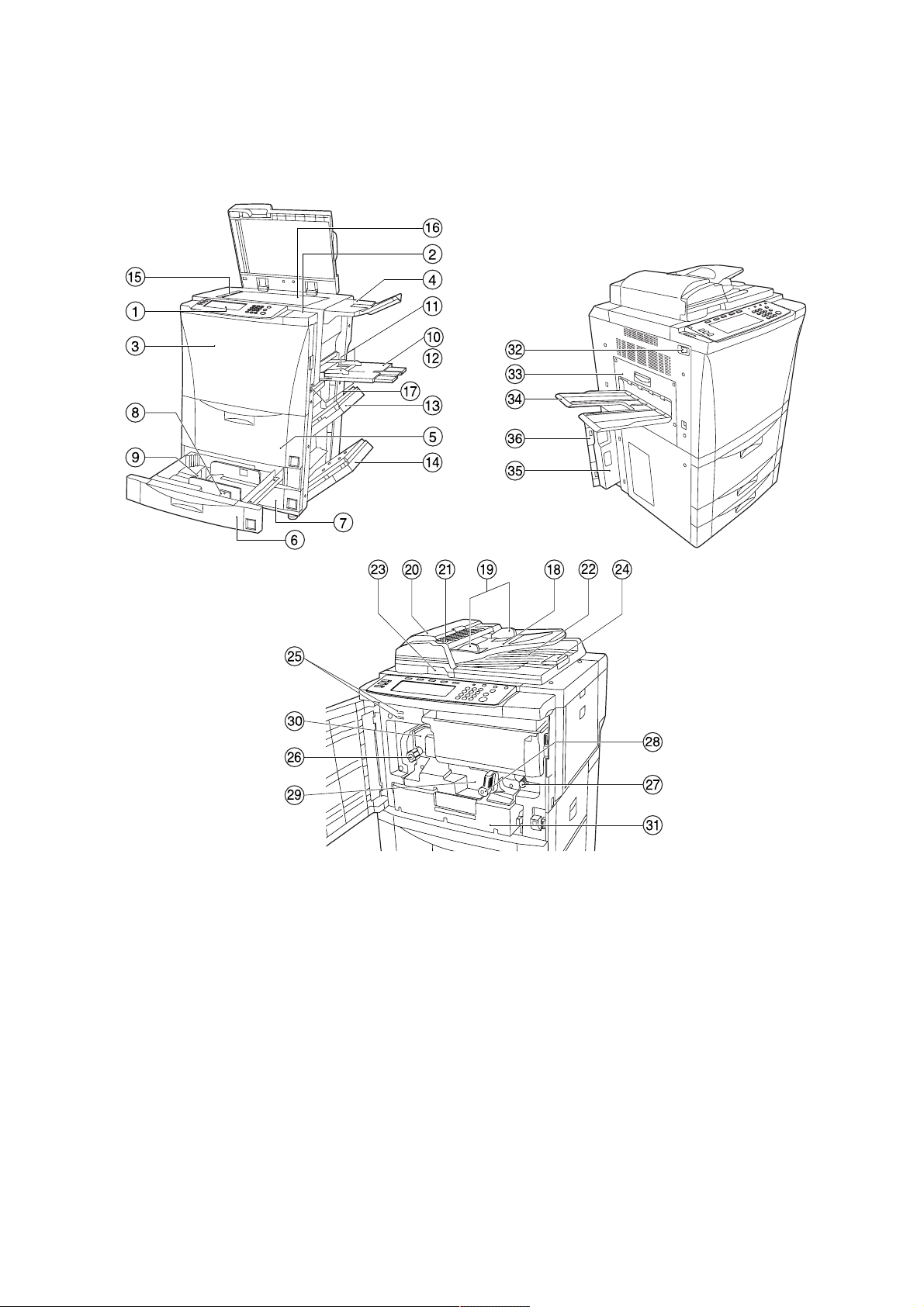
1-1-2 Parts names and their functions
(1) Copier
2CJ/2FA
1 Operation panel
2 Operation section right cover
3 Front cover
4 Original tray
5 Large paper deck
6 Upper cassette
7 Lower cassette
8 Width guide
9 Length guide
0 Bypass table
! Insert guides
@ Support guide
# Upper right cover
Figure 1-1-1
$ Lower right cover
% Original size indicator lines
^ Contact glass
& Handles for transport
* Original table
( Original insert guides
) DF original reversing cover
⁄ Original set indicator
¤ Original ejection cover
‹ DF opening/closing lever
› Ejection guide
fi Total counter
fl Fixing knob
‡ Paper feed section knob
— Paper conveying section
release lever
· Paper conveying section
‚ Fixing unit
ΠDuplex unit
„ Main switch
´ Ejection cover
‰ Ejection tray
ˇ Waste toner box
Á Waste toner box cover
1-1-3
Page 17
2CJ/2FA
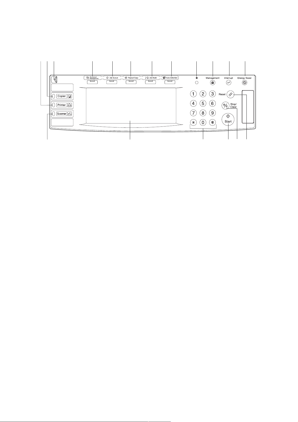
(2) Operation panel
#
1 Start key (indicator)
2 Stop/clear key
3 Reset key
4 Energy saver key (indicator)
5 Interrupt key (indicator)
6 Management key
7 *(default setting) key
8 Numeric keys
9 Touch panel
9
Figure 1-1-2
$%^&*0@ !
0 Brightness adjustment control dial
! Copier key (indicator)
@ Printer key (indicator)
# Scanner key (indicator)
$ Auto selection key (indicator)
% Job build key (indicator)
^ Repeat key (indicator)
& Job queue key (indicator)
* Document management key (indicator)
7
6 5 4
8 3
1
2
1-1-4
Page 18
1-1-3 Machine cross section
2CJ/2FA
3
8
6
9
0
!
2
4
7
5
1
Figure 1-1-3 Machine cross section
1 Paper feed section
2 Main charging section
3 Optical section
4 Developing section
5 Transfer and paper conveying section
6 Cleaning section
Light path
Paper and original path
7 Charge erasing section
8 Fixing section
9 Feedshift and eject section
0 Duplex section
! SRDF
1-1-5
Page 19

2CJ/2FA
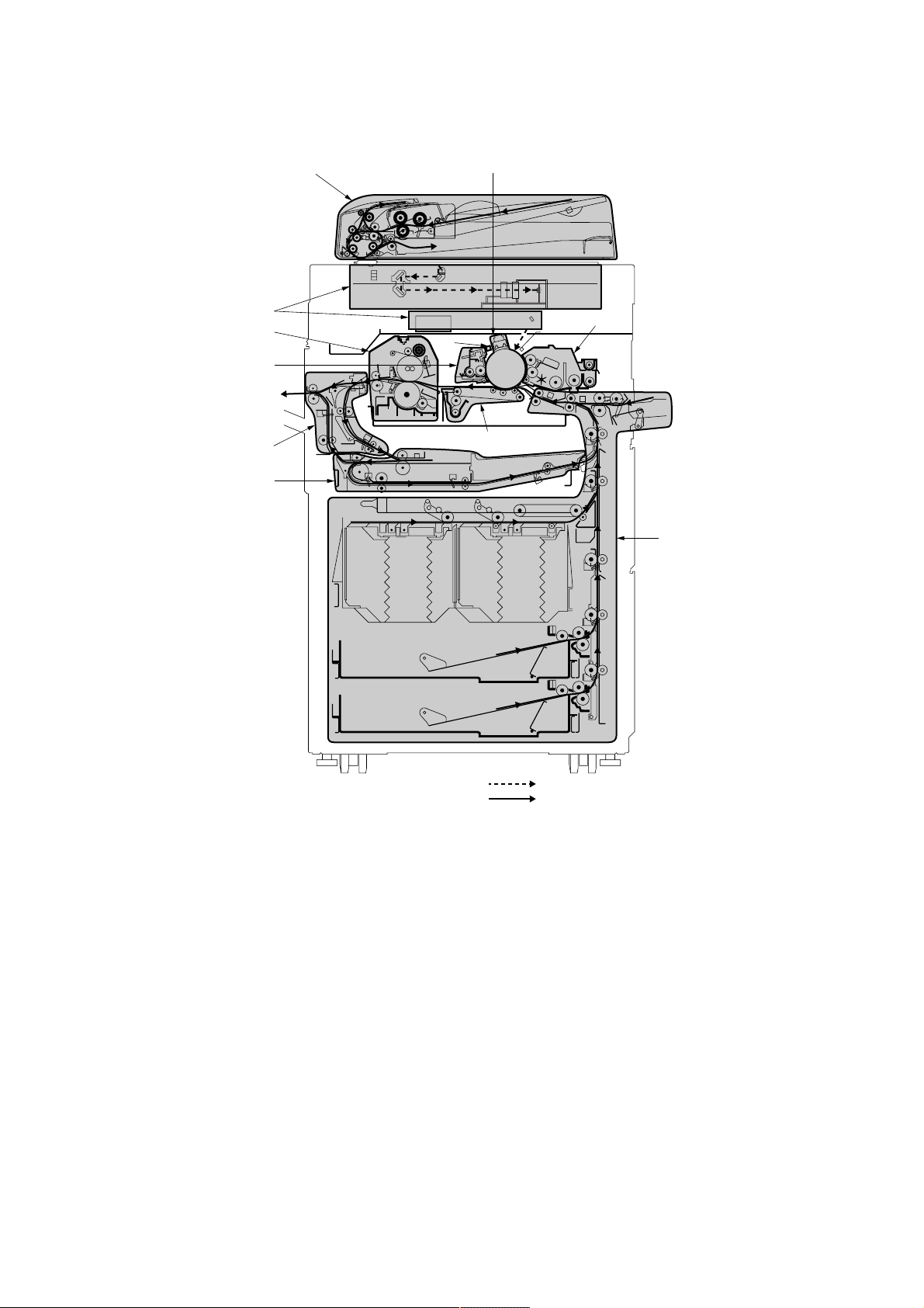
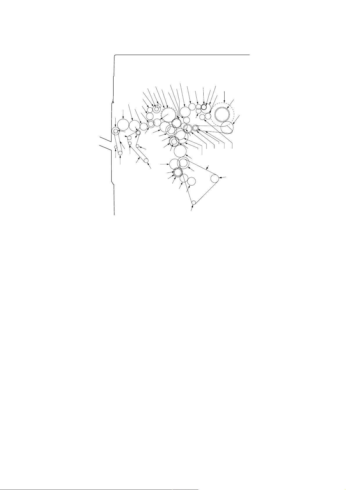
1-1-4 Drive system
(1) Drive system 1 (optical section)
6
6
Figure 1-1-4
1 Scanner motor pulley
2 Scanner drive belt
3 Scanner drive pulley
4 Scanner wire drum
5 Scanner wire
6 Scanner wire pulley
5
3
4
6
1
2
1-1-6
Page 20
(2) Drive system 2 (paper feed motor drive train)
2CJ/2FA
Á
Œ
›
°
·
‡
(
fl
‚
*
fi
⁄
7
„
6
)
¤
ˇ
1
2
3
4
5
‹
‰
´
8
9
0
!
@
1 Idle gear 20
2 Feed gear 22/32
3 Feed drive belt
4 Feed gear 22/32
5 Idle gear 20
6 Upper paper feed clutch gear
7 Idle sub gear 18
8 Feed clutch 4 gear
9 Idle gear 26
0 Paper feed gear 16
! Toner roller gear
@ Feed clutch 5 gear
# Paper feed gear 16
$ Toner roller gear
% Idle sub gear 18
^ Lower paper feed clutch gear
& Idle gear 40
* Idle gear 24
&
^
Figure 1-1-5
( Gear 42/32
) Feed clutch 2 gear
⁄ Gear 38T
¤ Gear 35
‹ Gear 29
› Idle gear 29
fi Idle gear 30
fl Feed gear 55/45
‡ Paper feed motor gear
— Gear 42/32
· Paper feed drive belt
‚ Tension pulley 20
ΠTension pulley 20
„ Tension pulley 20
´ Gear 42/32
‰ Feed clutch 3 gear
ˇ Tension pulley 20
Á Idle pulley 21
#
%
$
1-1-7
Page 21
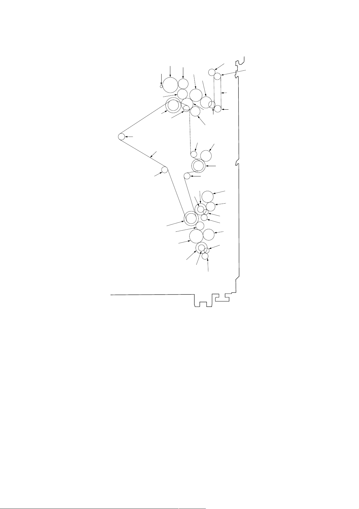
2CJ/2FA
(3) Drive system 3 (image forming motor drive train)
6
4
1
2
3
5
7
8
9
0
!
1 Drum
2 Drum gear 60/54
3 Drum pulley 26/26
4 Idle pulley
5 Developing gear 30
6 Developing idle gear 27
7 Drum drive belt
8 Idle pulley 24/72
9 Drum idle gear 45
0 Image forming motor gear
! Gear 53/44/33
„
Œ
‚
‡
·
@ Developing spiral gear
# Bypass clutch gear
$ Gear 18
% Idle gear 20
^ Idle gear 20
& Idle gear 20
* Clutch gear 26
( Clutch gear 26
) Clutch gear 26
⁄ Bypass clutch gear
¤ Paper feed pulley B gear
fi
°
fl
›
Figure 1-1-6
‹
¤
⁄
)
@
#
$
%
^
&
(
*
‹ Idle gear 30/15
› Registration upper gear 16
fi Gear 18
fl Feed clutch 1 gear
‡ Paddle A gear
— Idle gear 27
· Gear 18
‚ Registration upper gear 16
ΠRegistration clutch gear
„ Fixing drive gear
1 Developing gear 27
2 Main unit mixing gear 35
3 Toner gear 34
4 Paddle idle gear
5 Developing left spiral gear
1-1-8
4
789!
@
0
5
3
Figure 1-1-7 Developing section
6 Developing rear gear 25
7 Developing idle gear 27/36
8 Developing joint gear
9 Developing idle gear
0 Developing idle lower gear
2
6
#
1
! Developing upper gear
@ Developing lower gear
# Sub unit agitation gear 28
Page 22
(4) Drive system 4 (drive motor drive train)
ˆ
Ø
Ó
Ô
Ç
◊
˛
Ò
ı
¸
Ú
¯
Î
Ï
˝
”
¨
Í
Á
˜
1
Â
2
ˇ
˘
3
‰
´
¿
¡
4
5
Å
„
™
6
£
7
8
¢
·
⁄
0
)
‚
°
Œ
@
‡
fl
#
9
fi
$
%
›
^
‹
2CJ/2FA
&
*
¤
!
1 Oil roller gear 16
2 Heat roller
3 Heat roller gear
4 Fixing joint gear 36
5 Developing joint gear
6 Idle gear 22
7 Fixing drive gear 36
8 Idle gear 25
9 Cleaning drive belt
0 Cleaning drive gear
! Pulley 36
@ Feedshift gear 21
# Spiral roller gear 19
$ Blade thrust gear 36
% Oil supply roller gear 22
^ Drum
& Drum gear 60/54
* Transfer charger belt release clutch gear
( Idle pulley 21
) Loop gear 18
⁄ Idle gear 22
¤ Agitation gear 20
(
Figure 1-1-8
‹ Transfer belt
› Transfer belt drive roller
fi Idle gear 22
fl Fulcrum gear
‡ Idle gear 40
— Developing drive gear 45
· Oil roller gear
‚ Duplex gear 44
ΠIdle pulley 31/42
„ Developing gear 20
´ Motor idle gear 45
‰ Drive motor gear
ˇ Motor idle gear 56/25
Á Gear 38T
¨ Fixing eject joint gear
ˆ Eject joint gear
Ø Fixing eject joint gear
” Developing gear 20
Å Idle gear 28
Í Oil roller gear 16
Î Gear 30
Ï Gear 19
˝ Fixing eject joint gear
Ó Idle gear 40
Ô Idle gear 28
Æ Eject pulley 24
Ò Switchback drive belt
Ú Forwarding pulley
¸ Paper conveying belt pulley
˛ SB gear 19
Ç Feedshift pulley 22
– Pulley 16
ı Pulley 20
˜ Paper conveying belt pulley
 Pulley 24
¯ Duplex paper conveying belt
˘ Idle gear 40
¿ SB gear 24
¡ Gear 32
™ Gear 36
£ Idle gear 30
¢ Gear 31
1-1-9
Page 23

2CJ/2FA
(5) Drive system 5 (large paper deck)
7
8
3
1
2
1 Pulse gear
2 Gear 1.0-24
3 Lift pulley
4 Left lift belt assembly
5 Right lift belt assembly
6 Large paper deck lift motor gear
7 Large paper deck paper feed clutch 2 gear
8 Gear 18
9 Gear 24
0 Gear 18
! Idle gear 31
@ Gear 33
# Gear 18
5
!@#$%)⁄
9
6
^
0
&
6
Figure 1-1-9
$ Gear 28
% Idle gear 19
^ Gear 20
& Gear 18
* Gear 22
( Gear 18
) Gear 14
⁄ Gear 14
¤ Large paper deck paper feed clutch 1 gear
‹ Paper feed belt pulley
› Paper feed belt
fi Paper feed belt pulley
fl Large paper deck conveying clutch gear
¤
*(
2
3
4
1
‹
›
fi
fl
1-1-10
Page 24

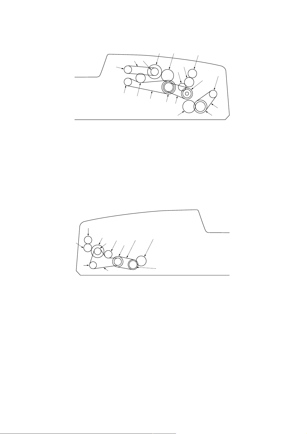
(6) Drive system 6 (duplex section)
9
0
&
8
1
2
^
7%$
3
#
@
!
5
6
Figure 1-1-10
2CJ/2FA
7
4
1 Duplex joint gear
2 Clutch gear 26
3 Paper conveying pulley 40
4 Paper conveying drive belt
5 Paper conveying tension pulley
6 Paper conveying pulley 20
7 Paper conveying pulley 20
8 Duplex registration gear 20/30
9 Clutch gear 26
0 Front transfer drive gear
! Gear 22
@ Gear 18
# Gear 17
$ Gear 40
% Duplex forwarding clutch gear
^ Gear 40
& Duplex reversing clutch gear
1-1-11
Page 25
2CJ/2FA
(7) Drive system 7 (SRDF)
6
1
Figure 1-1-11 SRDF (inside rear of machine)
1 Original feed motor pulley
2 Pulley 35/22/22
3 Idle gear 26
4 Original feed clutch gear
5 DF original feed pulley 18
6 DF forwarding pulley 18
7 Tension pulley
8 Original feed drive belt
9 DF forwarding belt
9
7
5
43
#
@
!
0
8
2
$
&
As viewed from machine rear
0 DF registration pulley 28/18
! Idle gear 15
@ Idle gear 20
# Switchback gear 18
$ DF registration drive belt
% Gear 22/35
^ Original conveying motor pulley
& Gear 28
* Original conveying drive belt 1
^
*
%
8
7
6
5
9
0
1
4
!
Figure 1-1-12 SRDF (inside front of machine)
1 Lower original conveying pulley 25/18
2 Gear 18/25
3 Eject gear 18
4 Middle original conveying pulley 18
5 Upper original conveying pulley 18
6 JAM release gear 24
3
2
As viewed from machine front
7 Joint gear 14
8 JAM release gear 14
9 Tension pulley
0 Eject drive belt
! Conveying drive belt 2
1-1-12
Page 26
2CJ/2FA-1
1-2-1 Drum
Note the following when handling or storing the drum.
• When removing the image formation unit, never expose the drum surface to strong direct light.
• Keep the drum at an ambient temperature between –20°C/–4°F and 40°C/104°F and at a relative humidity not higher
than 90% RH. Avoid abrupt changes in temperature and humidity.
• Avoid exposure to any substance which is harmful to or may affect the quality of the drum.
• Do not touch the drum surface with any object. Should it be touched by hands or stained with oil, clean it.
1-2-2 Developer and toner
Store the developer and toner in a cool, dark place. Avoid direct light and high humidity.
1-2-3 Installation environment
1. Temperature: 10 - 35°C/50 - 95°F
2. Humidity: 15 - 85%RH
3. Power supply: 120 V AC, 13 A/220 - 240 V AC, 4.9 A (ave.)
120 V AC, 15 A/220 - 240 V AC, 7.0 A (ave.) (75 cpm)
4. Power source frequency: 50 Hz ±0.3%/60 Hz ±0.3%
5. Installation location
• Avoid direct sunlight or bright lighting. Ensure that the photoconductor will not be exposed to direct sunlight or other
strong light when removing paper jams.
• Avoid extremes of temperature and humidity, abrupt ambient temperature changes, and hot or cold air directed onto
the machine.
• Avoid dust and vibration.
• Choose a surface capable of supporting the weight of the machine.
• Place the machine on a level surface (maximum allowance inclination: 1° ).
• Avoid air-borne substances that may adversely affect the machine or degrade the photoconductor, such as
mercury, acidic of alkaline vapors, inorganic gasses, NOx, SOx gases and chlorine-based organic solvents.
• Select a room with good ventilation.
6. Allow sufficient access for proper operation and maintenance of the machine.
Machine front: 1000 mm/39
3
/8" Machine rear: 100 mm/315/16"
Machine right: 700 mm/279/16" Machine left: 600 mm/235/8"
(63 cpm)
f
c
e
b
d
a
1181 mm/461/2"
a:
b: 685 mm/2615/16"
800 mm/311/2"
c:
d: 1530 mm/601/4"
e:
1390 mm/543/4"
f: 1375 mm/541/8"
Figure 1-2-1 Installation dimensions
1-2-1
Page 27
1-3-1 Unpacking and installation
(1) Installation procedure
Start
Unpack.
Remove the tapes.
2CJ/2FA-1
Remove the tapes of the duplex unit .
Connect the power cord.
Remove the pins holding light source units 1 and 2.
Remove the cleaning assembly retainers.
Set the cleaning assembly.
Load developer.
Install the upper developing seal.
Fitl the belt cleaning spacers and
lower cleaning roller (for 63 cpm only).
Set the fixing pressure.
Carry out initial developer setting.
(maintenance item U130)
Apply toner to the cleaning blade.
(maintenance item U160)
Set the cleaning blade.
Exit maintenance mode.
Load toner.
Install the original tray*.
Make test copies.
Completion of the machine installation.
*For inch models only.
1-3-1
Page 28
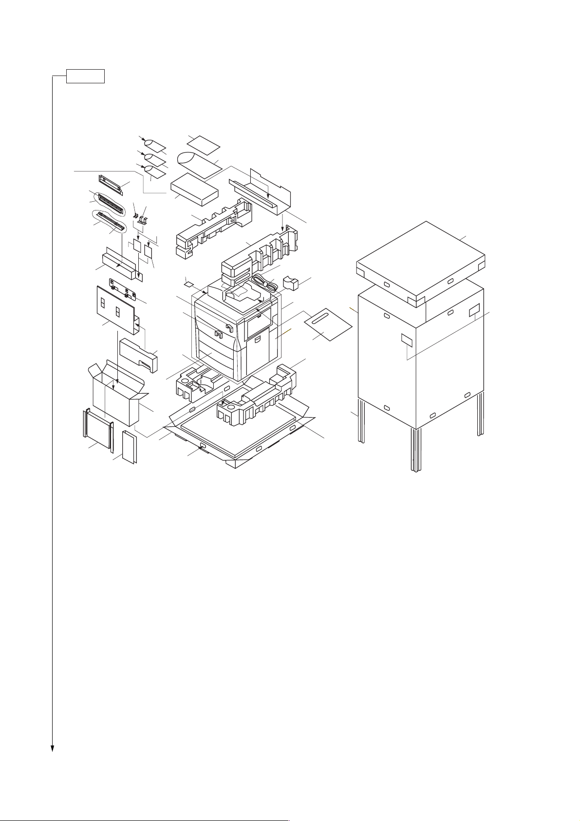
2CJ/2FA
Unpack.
‡
Ï
Ï
Í
›
fl
&
^*
$(
‚
%
„
%
Œ
fi
Á
ˆ
°·
Ô
%
´
#
‹
¨
Ø
%
%
´
@
!
3
˝
4
Å
Ó
4
∏
Ï
⁄
1
0
2
3
ˇ
9
7
8
¤
‰
6
Î
1 Copier
2 Upper spacer
3 Bottom pad
4 Upper pad
5 Bottom plate
6 Skid
7 Supports
8 Upper case
9 Outer case
0 Tank spacer
! Front transfer spacer
@ Rear transfer spacer
# Upper developing seal
$ Belt cleaning spacers
% Plastic bag
^ Paper labels
)
Figure 1-3-1 Unpacking
& Screws (M3 × 8 chromate)
* Cassette size labels
( Screws (M4 × 10 TP-A bronze)
) Hinge joints
⁄ Machine cover
¤ Bar code labels
‹ Attachment case
› Attachment spacer
fi Mounting plate assembly
fl Rail release plate
‡ Release fixing plate
° Release handle
· Shield gasket
‚ Connecting stoppers
ΠMounting support plates
„ Release adjusting plate
*1
5
´ Waste toner boxes
‰ Slider assembly
ˇ Eject pad
Á Screws (M4 × 12 TP-A chrome)
¨ Screws (M4 × 6 TP-A chrome)
ˆ Screws (M4 × 10 binding bronze)
Ø Screws (M4 × 6 binding bronze)
∏ Power code
Å DP spacer
Í Upper spacer of attachment
Î Side spacer of attachment
Ï Plastic bags
˝ Operation guide
Ó Plastic bag
Ô Clamp
*1: for 220 - 240 V specifications only.
*2: for 230 V specifications only.
*1
*2
1-3-2
Page 29
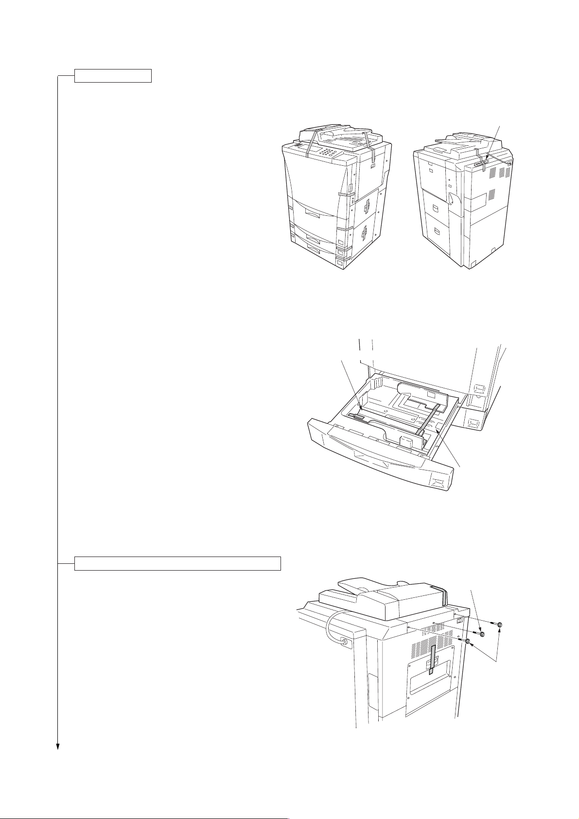
Remove the tapes.
1. Remove the tapes holding the SRDF.
2. Remove the tape holding the front cover.
3. Remove the tape holding the right cover.
4. Remove the tapes holding the large paper deck
and cassettes.
5. Remove the tape holding the bypass table.
6. Remove the tapes holding the power cord.
2CJ/2FA-1
Power cord
Figure 1-3-2
7. Draw out the upper cassette and remove the
tapes holding the cassette lift and pull out the
upper developing seal.
Remove the pins holding light source units 1 and 2.
1. Remove the tapes with the two pins holding light
source unit 1 and the one pin holding light source
unit 2 at the left side of the machine, and remove
the each pin.
2. Remove the tapes holding the eject cover and DF
original switchback cover.
Upper developing seal
Cassette lift
Figure 1-3-3
Light source
unit 2 pin
Figure 1-3-4
Light source
unit 1 pin
1-3-3
Page 30
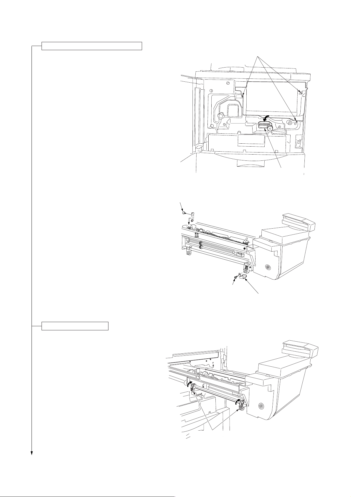
2CJ/2FA
Remove the cleaning assembly retainers.
1. Open the front cover and remove the three
screws holding the image forming unit. Tip the
transfer section release lever, then pull out the
image forming unit horizontally.
Caution: When pulling out the image forming unit,
hold the both of the image forming unit
firmly and do not touch the separation
claws.
Screws
Conveying release lever
Figure 1-3-5
2. Remove the screw holding the cleaning assembly
retainer (at the front side of the machine), then
remove the cleaning assembly retainer. Remove
the pin holding the cleaning assembly retainer (at
the rear side of the machine), then remove the
cleaning assembly retainer.
Set the cleaning assembly.
1. Turn the cleaning retaining levers in the direction
of the arrow and set the cleaning retaining levers
firmly.
Pin
Cleaning assembly retainer
(rear side)
Screw
Cleaning assembly retainer
(front side)
Figure 1-3-6
1-3-4
Cleaning retaining levers
Figure 1-3-7
Page 31

Load developer.
1. Lift the lock lever holding the developing
assembly through 90 degrees and slide the lever
on the top of the developing assembly in the
direction of the arrow, then release the nozzle of
the developing assembly from the toner hopper.
2. Remove the screw holding each of the front and
rear developing assembly retainers and lift the
levers for securing the developing assembly, and
then disconnect the positive connector and 4-pin
connector.
3. Hold the handle of the developing assembly and
remove the assembly from the copier.
Screw
Lock lever
4-pin connector
2CJ/2FA
Positive connector
Screw
Lever
Figure 1-3-8
Handle
4. Remove the three screws and disengage the two
hooks and then remove the upper developing
cover.
Caution: Be sure to place the developing
assembly on a level surface when
loading developer.
Developing assembly
Figure 1-3-9
Screws
Upper developing cover
Figure 1-3-10
1-3-5
Page 32

2CJ/2FA
5. Shake the developer bottle well to agitate the
developer.
6. While turning the developing gear (with the
marked arrow) in the direction of the arrow,
uniformly pour developer into the developing
assembly. (Pour two bottles of developer.)
Caution: Never turn the developing gear in the
reverse direction.
7. Refit the upper developing cover to the
developing assembly.
• When refitting the upper developing cover, be
sure to insert the large and small hooks until
they click into place and then secure with the
three screws.
Developing gear
Developer
Figure 1-3-11
Screws
Figure 1-3-12
Hooks
1-3-6
Page 33

2CJ/2FA-1
Install the upper developing seal.
1. Remove the two screws and fit the upper
developing seal using the removed screws.
• When fitting the upper developing seal, fit while
holding it toward the drum.
2. Insert the developing assembly back into the
image forming unit and connect the positive
connector and 4-pin connector.
3.
Lower the levers for securing the developing
assembly to lock the assembly and refit the screw
holding each of the front and rear developing
assembly retainers.
4.Slide the lever on the top of the developing
assembly in the direction of the arrow and lower
the lock lever through 90 degrees to secure the
nozzle of the developing assembly to the toner
hopper.
Screws
Upper developing seal
Figure 1-3-13
Levers for securing
the developing assembly
5. Push back the image forming unit its original
position and then fasten with the three screws
fastened the unit .
Lock lever
Lever
Figure 1-3-14
Screws
Conveying release lever
Figure 1-3-15
1-3-7
Page 34

2CJ/2FA-1
Fit the belt cleaning spacers and lower
cleaning roller (for 63 cpm only).
1. Remove the screw and draw the conveying
section out laterally.
2. Remove the front and rear transfer spacers.
Conveying section
Screw
Figure 1-3-16
Rear transfer spacer
3. Remove the stop rings and bearing from the
transfer charger belt shaft.
1-3-8
Front transfer spacer
Figure 1-3-17
Stop ring
Bearing
Bearing
Stop ring
Figure 1-3-18
Page 35

2CJ/2FA-1
4. Disconnect the 1-pin connector on the white wire,
1-pin connector on the red wire and the 1-pin
connector on the green wire. Shift the transfer
charger belt in the direction of the arrow, then
remove by lifting it.
Caution: Never touch the transfer charger belt.
5. Remove the four screws and disconnect the 1-pin
connector on a green wire, and then remove the
belt cleaning housing.
1-pin connector
(green wire)
Figure 1-3-19
Screws
1-pin connector
(white wire)
Belt cleaning
housing
1-pin connector
(red wire)
Screws
6. Fit the lower cleaning roller to fixing unit with the
two screws.
1-pin connector
(green wire)
Figure 1-3-20
Lower cleaning roller
Figure 1-3-20-1
1-3-9
Page 36

2CJ/2FA-1
7.
Fit the belt cleaning spacers as shown in the
diagram.
8.
Use the supplied four screws to tighten the belt
cleaning spacers and the belt cleaning housing
together.
• Reattach the film of the belt cleaning housing to
its original position under the guide plate.
Belt cleaning spacers
Figure 1-3-21
9.
Connect the 1-pin connector on the green wire.
10.
Refit the transfer charger belt.
• Be sure to insert the grounding bearing into the
grounding plate.
11.
Connect the 1-pin connector on the green wire, 1pin connector on the red wire and the 1-pin
connector on the white wire, and then fit the stop
rings and bearings to the transfer charger belt
shaft.
Set the fixing pressure.
1. Open the fixing eject cover.
Guide plate
Figure 1-3-22
Film
1-3-10
Fixing eject cover
Figure 1-3-23
Page 37

2. Turn the fixing pressure screws in the direction of
the clockwise and tighten it, then set the fixing
pressure.
3. Close the fixing eject cover.
4. Push back the transfer section its original position
and lift the transfer section release lever to the its
original position, then fasten it.
Remove the tapes of the duplex unit.
1. Draw out the duplex unit and remove the three
tapes holding the duplex unit.
2CJ/2FA-1
Fixing pressure screw
Figure 1-3-24
Duplex cover
Tapes
Connect the power cord.
Figure 1-3-25
1. Connect the power cord to the machine.
2. Insert the power plug into the wall outlet.
Carry out initial developer setting. (mentenance item U130)
1. Turn the main switch on with opening the front cover.
2. The machine starts warming up, after “Close the front cover” message is displayed, enter the maintenance mode
by entering “10871087” using the numeric keys.
3. Enter “130” using the numeric keys and press the start key.
4. Close the front cover.
5. Press the start key to execute the maintenance item.
• In approximately 2 minutes, the toner control level and toner sensor control voltage are automatically set and the
settings displayed on the touch panel.
Display example
INPUT: 104 (toner sensor output voltage)
CONTROL: 125 (Toner sensor control voltage)
FIRST TARGET: 103 (Toner control reference voltage)
HUMID: 65 (Absolute humidity)
6. Press the stop/clear key.
Apply toner to the cleaning blade (maintenance item U160)
1. Enter “160” using the numeric keys and press the start key.
2. Press the start key to execute the maintenance item.
• Toner is applied to the drum and then the drive stops automatically.
1-3-11
Page 38

2CJ/2FA-1
Set the cleaning blade.
1. Open the front cover and remove the three
screws holding the image forming unit. Tip the
transfer section release lever, then pull out the
image forming unit horizontally.
2. Check that the toner is applied to the drum and
loosen the blade retaining screw at the left side of
the image forming unit, then slide the blade
release lever in the direction of the arrow.
• The cleaning blade is set and the cleaning blade
contacts with the drum.
Image forming unit
Conveying release lever
Figure 1-3-26
Blade release lever
3. Refasten the blade retaining screw, then fasten
the blade release lever.
4. Push back the image forming unit its original
position and lift the conveying release lever up
the its original position, and then fasten with the
three screws fastened the image forming unit .
5. Close the front cover.
6. After driving stops, press the stop/clear key.
Exit maintenance mode.
1. Enter “001” using the numeric keys and press the
start key.
• The machine exits the simulation mode.
Blade retaining screw
Figure 1-3-27
Screws
Conveying release lever
Figure 1-3-28
1-3-12
Page 39

Load toner.
1. Open the operation right cover.
2. Hold a new toner bottle upside down and tap the
bottom approximately 10 times.
2CJ/2FA
Operation right cover
Figure 1-3-29
3. Shake the toner bottle up and down and from
side to side approximately 10 times.
Toner bottle
Figure 1-3-30
Figure 1-3-31
1-3-13
Page 40

2CJ/2FA
4. Push the round hole of the toner bottle to the
metal pin at the opening for toner replenishment.
5. While pushing down the toner bottle, turn it 90°
clockwise.
6. Wait until toner drops (approx. 60 seconds).
Metal pin
Figure 1-3-32
7. To drop toner completely, tap the side of the
toner bottle approximately 10 times.
1-3-14
Figure 1-3-33
Figure 1-3-34
Page 41

8. Turn the toner bottle to the original position while
pushing it down, and gently remove it from the
opening for toner replenishment.
9. Close the operation right cover.
Install the original tray.*
1. Hook the grooves of the original tray to the pins
(two) at the right side of the machine, then install
the original tray to the machine.
*Inch models only.
2CJ/2FA
Figure 1-3-35
Make test copies.
1. Load paper in a casette and make test copies.
Completion of machine installation.
1-3-15
Page 42

2CJ/2FA-1
1-3-2 Setting initial copy modes
Factory settings are as follows:
Maintenance
item No.
U253
U254
U255
U258
U260
U263
U264
U266
U330
U331
U343
U344
U347
User
settings
Contents
Switching between double and single counts
Turning auto start function on/off
Setting auto clear time
Switching copy operation at toner
empty detection
Changing the copy count timing
Setting the paper ejection when copying from
the DF
Setting the display order of the date
Setting the number of days after which to
automatically delete documents
Setting the number of sheets to enter stacking
mode during sort operation
Switching the paper ejection mode
Switching between duplex/simplex
copy mode
Setting preheat/energy saver mode
Setting auto drawer size detection
Exposure mode
Exposure steps
Original image quality
Paper selection
Default drawer
Default magnification
Margin width
Border erase width
Copy limit
Auto shutoff time
Auto preheat time
Factory setting
Double count (A3/LEDGER)
ON
90s
SINGLE MODE, 5
EJECT
Face down
Month-day-year (inch)
Day-month-year (metric)
7 days
100
FACE UP
Simplex copy
Energy Star
ON (inch), OFF (metric)
Manual
1 step
Text+Photo
APS
Drawer1
Manual
Left: 6 mm /
Outside border: 6 mm /
Center area: 6 mm /
1
/4" Top: 0 mm / 0"
1
/4"
1
/4"
999
90
15
1-3-16
Page 43

1-3-3 Installing the key counter (option)
Key counter installation requires the following parts:
Key counter set
Contents of the set:
• Key counter cover (P/N 2A360010)
• Key counter retainer (P/N 66060030)
• Key counter cover retainer
• Key counter mount (P/N 66060040)
• Key counter assembly (P/N 41529210)
• Four (4) M4 × 6 bronze TP-A screws (P/N B4304060)
• Two (2) M4 × 10 bronze TP-A screws (P/N B4304100)
• One (1) M4 × 20 bronze TP-A screw (P/N B4304200)
• One (1) M4 × 6 chrome TP-A screw (P/N B4104060)
• One (1) M3 × 8 bronze binding screw (P/N B1303080)
• One (1) M4
• Two (2) M3 × 6 bronze flat-head screws (P/N B2303060)
• Two (2) M4 × 10 tap-tight S binding screws (P/N B3024100)
• Two (2) M4 × 10 tap-tight P chrome binding screws (P/N B8014100)
• One (1) M3 bronze nut (P/N C2303000)
<Procedure>
1. Fit the key counter assembly to the key counter
retainer using the two screws and nut.
2. Fit the key counter mount to the key counter cover
using the two screws, and attach the key counter
retainer to the mount using the two screws.
(P/N 2A369704)
(P/N 66060022)
×
30 bronze binding screw (P/N B1304300)
×
6 screws
M4
(B4304060)
M3 nut (C2303000)
2CJ/2FA-1
Key counter retainer (66060030)
Key counter mount (66060040)
3. Remove the four screws and detach the middle right
cover from the machine.
4. Cut out the aperture plate on the middle right cover
using nippers.
M4
×
6 screws (B4304060)
Key counter assembly (41529210)
M3 × 6 flat-head screws (B2303060)
Figure 1-3-36
Key counter cover (2A360010)
Aperture plate
Middle right cover
Figure 1-3-37
1-3-17
Page 44

2CJ/2FA-1
5. Pass the 4-pin connector of the key counter through
the apertures in the key counter cover retainer and
middle right cover, and insert into the 4-pin connector
inside the machine.
6. Seat the projection of the key counter cover retainer
in the aperture in the middle right cover, and fasten
them both to the machine using the two screws.
7. Refit the screw to the machine of the middle right
cover.
8. Fit the key counter cover with the key counter
assembly inserted to the key counter cover retainer
on the machine.
4-pin connector
4-pin connector
Aperture
Middle right cover
Key counter cover retainer
(66060021)
Screw
×
20 screw
M4
(B4304200)
Key counter cover
M4 × 6 screw
(B4104060)
Figure 1-3-38
9. Insert the key counter into the key counter assembly.
10. Turn the main switch on and enter the maintenance mode.
11. Run maintenance item U204 and select “KEY COUNTER.”
12. Exit the maintenance mode.
13. Check that the message requesting the key counter to be inserted is displayed when the key counter is pulled out.
14. Check that the counter counts up as copies are made.
1-3-18
Page 45

1-3-4 Installing the cassette heater (option)
2CJ/2FA
<Procedure>
1. Remove the four screws holding the lower rear cover
and then the cover.
2. Remove the two screws securing the main PCB
shield and open the main PCB shield.
3. Remove the four screws holding the large paper
deck and then the deck.
4. Pull the upper and lower cassettes out.
5. Fit the cassette heater using the tapes and then
pass the wires through the clearance under the
machine rear and let the them out.
Screws
Screws
Large paper deck
Figure 1-3-39
Cassette heater
6. Remove the open connector from the 2-pin
connector of the machine, and insert the 2-pin
connector of the cassette heater into the 2-pin
connector of the machine.
7. Secure the wires using the clamp.
8. Refit all the removed parts.
Figure 1-3-40
2-pin connector
2-pin connector
Figure 1-3-41
1-3-19
Page 46

2CJ/2FA
1-3-5 Installing the multi finisher (option)
<Procedure>
1. Fit the release fixing plate to the ejection cover of the
copier with the two M4 × 12 TP screws.
2. Remove the two screws from the ejection cover of
the copier and fit the release adjusting plate with the
removed two screws and the two M4 × 6 TP screws
by aligning the lower end.
Ejection cover
Ejection cover
Release fixing plate
Figure 1-3-42
3. Insert the two rail unit mounting plate stoppers into
the holes of the rail unit mounting plate.
Release
adjusting plate
Figure 1-3-43
Rail unit mounting plate
Rail unit mounting
plate stoppers
1-3-20
Figure 1-3-44
Page 47

4. Remove the two screws from the copier and fit the
rail unit mounting plate with the removed two screws
by aligning the lower end.
5. Fix the rail unit mounting plate stoppers with the two
M4 × 6 binding screws.
6. Attach the connecting sponge to the side plate of the
finisher by aligning it to the lower end “a” of the
narrow area and the front end “b” of the side plate.
2CJ/2FA
Rail unit mounting plate
Rail unit mounting
plate stopper
Rail unit mounting
plate stopper
Figure 1-3-45
7. Remove the screw and then remove the release
hook.
8. Remove the three pins and then remove the
connecting rail.
Release hook
b
a
a
Connecting sponge
Figure 1-3-46
Connecting rail
Figure 1-3-47
Pins
1-3-21
Page 48

2CJ/2FA
9. Remove the screw and then remove the gray handle
of the release hook. Fit the green release hook
handle with the removed screw.
10. Fit the latch plate with the two pins that have been
removed in step 8.
Gray handle
Release hook
Green release hook handle
Figure 1-3-48
11. Fit the release hook with the screw that has been
removed in step 7.
Latch plate
Pins
Figure 1-3-49
Release hook
1-3-22
Figure 1-3-50
Page 49

12. Open the front cover.
13. Remove the four blue screws locking each of the two
separate retainers to the intermediate tray and
detach both retainers.
14. Pull out the intermediate tray.
15. Remove the strip of fixing tape from the release
lever.
2CJ/2FA
Intermediate tray
Separate
retainers
Figure 1-3-51
Release lever
16. Raise the release lever to open the intermediate tray,
and then remove the four strips of fixing tape.
Intermediate tray
Strip of fixing tape
Strip of fixing
tape
Strip of fixing tape
Figure 1-3-52
Strip of fixing tape
Strip of fixing tape
Release lever
Intermediate tray
Figure 1-3-53
1-3-23
Page 50

2CJ/2FA
17. Insert a stapler cartridge into each of the staplers and
of the intermediate tray. Press on the cartridges until
they are securely locked.
For 220 - 240 V specifications only
18. Attach the shield gasket to the rear side opening
plate of the intermediate tray.
• Attach it after cleaning the rear side
opening plate with alcohol.
• Attach it by aligning with the end of the rear side
opening plate between the notch and the cable tie.
Stapler cartridge
Stapler
Stapler
Intermediate tray
Figure 1-3-54
Rear side opening plate
Notch
Shield gasket
Intermediate
tray
Cable tie
Figure 1-3-55
1-3-24
Page 51

2CJ/2FA
19. Push the release lever to close the intermediate tray and insert it into its original position.
20. Fit the main tray with two hexagonal nuts.
21. Secure the main tray with two pins.
22. Attach the sub tray to the finisher by inserting the projections at the front and back of the sub tray into the holes of the
finisher.
23. Attach label A to the recessed portion on the side of the main tray.
24. Attach label B to the recessed portion on the side of the sub tray.
Main tray
Label A
25. Remove the 2-pin connector from the main tray unit
and then remove the five screws to remove the rear
cover.
Hexagonal nuts
Label B
Pins
Figure 1-3-56
Rear cover
Sub tray
Projections
Hole
Projections
Hole
26. Remove the four screws and then remove the lower
right stay.
2-pin
connector
Figure 1-3-57
Lower right stay
Figure 1-3-58
1-3-25
Page 52

2CJ/2FA
27. Insert the rail unit into the lower part of the finisher.
28. Pull out the intermediate tray.
29. Fix the rail unit with the four M4 × 10 binding screws.
• As shown in the illustration, the fixing
positions of the M4 × 10 binding screws may be
different depending on the finisher model.
30. Insert the intermediate tray into its original position.
Finisher
Rail unit
Figure 1-3-59
31. Refit the lower right stay to its original position.
32. Refit the rear cover to its original position and
connect the 2-pin connector of the main tray unit.
33. Pull out the rail unit and insert the pin of the rail unit
to the connecting section of the rail unit mounting
plate.
Rail unit
Rail unit
Figure 1-3-60
Connecting section
Pins
Rail unit mounting plate
1-3-26
Figure 1-3-61
Page 53

2CJ/2FA-1
34. Insert the stopper to the connecting section and fix it
with the two M4 × 6 binding screws.
35. Connect the signal cable of the finisher to the
connector of the copier.
For 230 V specifications only, fit the clamp to the
signal cable and use the screw of the rear middle
cover of the copier to tighten them together.
Stopper
Stopper
Figure 1-3-62
Signal cable
Clamp
Figure 1-3-63
36. With the release hook handle pulled, loosen the two screws and the two M4 × 6 TP screws and adjust the mounting
position of the release adjusting plate so that the claw of the latch plate is positioned at the center of the opening of
the release adjusting plate.
37. Connect the finisher to the copier.
• The pin of the release adjusting plate is inserted into the hole of the finisher.
38. Close the front cover.
39. Plug the copier’s power cable into a wall outlet and turn the copier on from the main switch.
Finisher
Hole
Pin
Release
adjusting plate
Screw
Claw
Figure 1-3-64
Screw
Opening
Screw
1-3-27
Page 54

2CJ/2FA
Correcting Paper Curling
1. Set the machine in the non-sort mode and run paper
through the machine to make a test copy.
2. Check if the paper that is ejected from the finisher is
curled. If it is, make the following adjustment.
If the Paper Curls Downward (figure 1-3-65 “a”)
1. Open the front cover.
2. Rotate the lower lever by one mark in the direction of
the higher numbers.
Note: There are 5 marks. The lever is set to the first
mark when shipped.
3. Close the front cover.
4. Run paper through the machine and check if it is still
curled downward.
5. Repeat steps 1 to 4 until the ejected paper does not
curl downward anymore.
ab
Figure 1-3-65
1
Lower lever
2
3
5
4
1-3-28
Figure 1-3-66
Page 55

If the Paper Curls Upward (figure 1-3-65 “b”)
1. Open the front cover.
2. Remove the three screws locking down the inner left
cover followed by the cover.
2CJ/2FA
Inner left cover
Figure 1-3-67
3. Rotate the upper lever by one mark in the direction of
the higher numbers.
Note: There are 5 marks. The lever is set to the first
mark when shipped.
4. Close the front cover.
5. Run paper through the machine and check if it is still
curled upward.
6. Repeat steps 1 to 5 until the ejected paper does not
curl upward anymore.
7. When the correction is completed, reattach the inner
left cover.
4
3
2
Figure 1-3-68
5
Upper lever
1
1-3-29
Page 56

2CJ/2FA
1-3-6 Installing the side deck (option)
<Procedure>
1. Remove the two screws from the support.
Screws
Figure 1-3-69
2. Cut out the three aperture plates on the upper right
cover using nippers.
3. Insert the lower merge guide into the upper right
cover. Open the upper right cover and secure the
lower merge guide with two screws (M4 × 06 binding
screws).
Upper right cover
Aperture plates
Figure 1-3-70
Upper right cover
1-3-30
Screws
(binding M4 × 06)
Lower merge guide
Figure 1-3-71
Page 57

4. Close the upper right cover. While holding the lower
merge guide downward, secure the guide with two
screws (M4 × 08 TP-P tight screws).
Lower merge guide
Figure 1-3-72
Screws
(TP-P tight M4
2CJ/2FA
×
08)
5. Open the upper right cover. Insert the upper merge
guide into the cover from the inside and secure with
two screws (M4 × 06 binding screws).
6. Close the upper right cover. While holding the upper
merge guide upward, secure the guide with two
screws (M4 × 08 TP-P tight screws).
Upper right cover
Screws
(binding M4
Figure 1-3-73
Screws
(TP-P tight M4
Upper merge guide
×
06)
×
08)
Figure 1-3-74
Upper merge guide
1-3-31
Page 58

2CJ/2FA
7. Remove the two screws from the lower rear right
cover, the screw from the lower front right cover, and
then remove the lower middle right cover.
8. Refit the screws removed in step 7 to the lower rear
right cover and lower front right cover.
9. Insert the folded part of the interlock switch into the
slot in the lower rear right cover and secure with a
screw (M4 × 12 flat-head screw).
Lower front right cover Lower rear right cover
Lower middle
right cover
Screw
Screws
Figure 1-3-75
Interlock switch
Screw
(flat-head M4
×
12)
10. Pull out the rail retainer of the deck and insert it
between the frame and the lower right cover.
1-3-32
Figure 1-3-76
Lower right cover
Figure 1-3-77
Retainer
Page 59

11. Open the lower vertical conveying cover and align
the V-shaped groove of the retainer with the center of
the scale located at the base. Then secure the
retainer with two screws (M4 × 06 TP screws).
12. If the gaps between the copier and the side deck at
the top and bottom are not even after installing the
side deck, loosen the two height adjusting screws
and move the retaining rail in the direction of the
arrow by the necessary number of marks so that the
gaps become even, and retighten the screws.
(TP screw M4
Figure 1-3-78
Screws
×
2CJ/2FA
06)
Retaining rail
13. Connect the signal cable for the deck to the
connector on the copier.
14. Connect the power plug to the wall outlet and turn
the main switch on.
15. Press the right down switch to descend the lift until it
reaches lower limit.
16. Load paper in the side deck.
17. Run maintenance item U034 (Adjusting the print start
timing) and make a test copy.
18. Measure the discrepancy L (mm) between the center
of the test copy and the optical axis. If L is 1.0 mm or
above, loosen the two screws of the retainer and
move the V-shaped groove on the retainer by the
measured amount L and retighten the screws.
• If the line is shifted to the front ( a ), move the V-
shaped groove of the retainer toward the front.
• If the line is shifted to the rear ( b ), move the V-
shaped groove of the retainer toward the rear.
Side deck
Gap
Gap
Adjusting screws
Retaining rail
Mark Mark
Figure 1-3-79
L
L
a b
Figure 1-3-80
1-3-33
Page 60

2CJ/2FA-1
1-3-7 Installing the printing system (option)
<Procedure>
1. Remove 2 screws and take off the cover.
Cover
Figure 1-3-81
2. Push the printing system all the way in along the
rails, and fasten it to the controller box with 2 screws.
Install the (optional) printer network kit.
3. Remove 2 screws and take off the cover.
4. Push the printer network kit all the way in along the
rails, and fasten it to the controller box with 2 screws.
Printing system
Figure 1-3-82
1-3-34
Cover
Printer
network kit
Figure 1-3-83
Page 61

Install the (optional) HD-4 hard disk.
y
5. Remove 2 screws and take off the cover.
6. Push the HD-4 hard disk all the way in along the
rails, and fasten it to the controller box with 2 screws.
• After installation, the hard disc must be formatted.
Turn ON the power, go to the printer screen and
select the “Printer Menu” followed by “Hard Disk” and
then “Format”.
Installing the Optional Bar-Code Reader
7. Fasten the serial connector in place with 2 screws.
• After installation, the barcode reader must be set to
ON using the following procedure. Turn ON the
power, go to the printer screen and select “Printer
Menu”, “Interface”, “Serial”, “Detailed Settings”,
“Barcode”, “ON”, “Emulation”, “Change Interface”,
“Serial”, “PCL6”. Then turn the main switch off and
on.
Cover
2CJ/2FA-1
HD-4
hard disk
Figure 1-3-84
Installing the Optional Memory DIMM
8. Remove the printing system, and insert the optional
memory DIMM firmly into either of the memory slots.
Push the DIMM firmly into the slot so that the two
hooks (one hook at each end of the slot) snap
closed.
• The board provides two DIMM slots, and can accept
up to two optional DIMMs. If installing a single DIMM,
you can use either slot.
Serial connector
Screws
Figure 1-3-85
Optional memory DIMM
Hooks
Hooks
Memor
slots
Figure 1-3-86
1-3-35
Page 62

2CJ/2FA-1
1-3-8 Installing the scanning system (option)
<Procedure>
1. Remove the two screws securing the cover CF and
then the cover.
2. Remove the six screws securing the copier rear
middle cover A and then the cover.
3. Remove the eight screws securing the shield upper
cover and then the cover.
* When removing the shield upper cover, remove the
2-pin connector of the cooling fan in advance.
Rear middle
cover A
Cover CF
Figure 1-3-87
4. Remove the two screws and remove the cover.
5. Insert the scanner board through the opening and
connect the CN1 connector of the scanner board to
the CN4 connector of the main PCB of the copier.
Shield upper cover
CN4
2-pin
connector
Figure 1-3-88
CN1
Scanner board
Cover
Screws
1-3-36
Figure 1-3-89
Page 63

6. Fasten the scanner board to the controller-box cover
with two screws.
7. Refit the covers that have been removed in step 1 to
3 and the 2-pin connector of the cooling fan.
230 V specifications only
8. Fit the Ethernet cable to the core by winding it one
turn around the core.
9. Fit the Ethernet cable described in step 7 to the
Ethernet cable connector.
2CJ/2FA-1
Scanner board
Screws
Figure 1-3-90
Ethernet cable connector
230 V specifications only
10. Fasten the Ethernet cable with the clamp to the
screw on the right side at the lower rear of the copier
cover.
Core
Figure 1-3-91
Screw
Clamp
Figure 1-3-92
1-3-37
Page 64

2CJ/2FA-1
1-3-9 Installing the tandem kit (option)
<Procedure>
1. Remove the two screws securing the cover CF and
then the cover.
2. Remove the six screws securing the copier rear
middle cover A and then the cover.
3. Remove the four screws securing the copier rear
lower cover and then the cover.
4. Remove the 14 screws securing the shield upper
and lower covers and then the covers.
* When removing the shield upper and lower covers,
remove the 2-pin connector of the cooling fan in
advance.
Rear middle
cover A
Cover CF
Rear
lower cover
Figure 1-3-93
Shield upper cover
5. Remove the two screws securing the interface
mounting plate and then the plate.
6. Remove the two screws securing the interface cover
and then the cover.
2-pin connector
Shield lower cover
Figure 1-3-94
Interface
mounting plate
Interface cover
1-3-38
Figure 1-3-95
Page 65

7. Insert CN2 on the assembly relay PCB into CN1 on
y
the interface PCB for installation.
CN1
2CJ/2FA-1
Interface PCB
CN2
8. Insert CN1 on the assembly relay PCB into CN5 on
the main PCB of the copier.
×
9. Secure the interface PCB with two M4
6 binding
screws.
10. Insert the 2-pin connector on the S-BOX wire into 2pin connector CN3 on the interface PCB.
CN5
Assembly
relay PCB
S-BOX wire
Assembl
relay PCB
Figure 1-3-96
CN1
Figure 1-3-97
Screws
(M4 × 6
CN3
Interface PCB
binding)
Figure 1-3-98
1-3-39
Page 66

2CJ/2FA-1
11. Secure the interface mounting plate with the two
screws removed in step 5.
12. Secure the connector of the interface PCB to the
×
interface mounting plate with two M2.6
5 brass
binding screws.
13. Refit the shield upper and lower covers, the 2-pin
connector of the cooling fan, the copier rear lower
cover, the copier rear middle cover A, and the cover
CF.
14. Connect the interface cable to the connector of the
interface PCB.
Interface mounting plate
Screws
Screws
(M2.6 × 5
brass binding)
Figure 1-3-99
Figure 1-3-100
Interface cable
1-3-40
Page 67

2CJ/2FA
1-4-1 Copier management
This copier is equipped with the maintenance mode for service personnel and the management mode that can be used also
by users (mainly by copier administrator). In this copier management mode, settings such as default settings can be
changed.
(1) Using the copier management mode
Start
Press the * (Default setting) key.
Press the [Management] key.
Enter the
management code.
Press the [Weekly timer]
([Week timer]) key.
Enter the
management code.
Press the [Copy default] key.
Enter the
management code.
Press the [Machine default] key.
Enter the
management code.
Press the [Bypass setting] key.
Enter the
management code.
Press the [Document
management] key.
Execute department management items (page 1-4-2).
Press the [Close] key.
Make weekly timer settings
(page 1-4-2).
Press the [Close] key.
Make copy default settings
(page 1-4-3).
Press the [Close] key.
Make machine default settings
(page 1-4-5).
Press the [Close] key.
Make bypass settings
(page 1-4-6).
Press the [Close] key.
Enter the
management code.
Press the [BOX management]
([Hard Disk management]) key.
Enter the
management code.
Press the [Print Form] key.
Press the [Language] key.
Make document management
default settings (page 1-4-6).
Press the [Close] key.
Execute hard disk management
items (page 1-4-7).
Press the [Close] key.
Output the setting list
(page 1-4-7).
Press the [Close] key.
Set the language (page 1-4-7).
End
1-4-1
Page 68

2CJ/2FA
(2) Setting department management items
Registering a new department code
Sets a department code and the limit of the
number of copies for that department.
1. Press the [ID-code Reg./Del.] key.
2. Press the [Register] key and press the [#
keys].
3. Enter a department code (8-digit) using the
numeric keys and press the [# keys].
4. Enter the number of copies limit using the
numeric keys. The copy limit can be set to any
1 page increment between 1 and 999999.
Entering “0” enables unlimited copying.
5. Press the [Close] key.
6. Press the [Close] key.
7. Press the [On] key.
8. Press the [Close] key.
Deleting a department code
1. Press the [ID-code Reg./Del.] key.
2. Select the department code to be deleted and
press the [Delete] key.
3. Select “Yes” or “No”.
4. Press the [Close] key.
5. Press the [On] key.
6. Press the [Close] key.
Altering the copy limit
1. Press the [# of copy correct] key.
2. Select the department code to be altered and
press the [Correction] key.
3. Enter the number of copies limit using the
numeric keys. The copy limit can be set to any
1 page increment between 1 and 999999.
Entering “0” enables unlimited copying.
4. Press the [Close] key.
5. Press the [Close] key.
6. Press the [On] key.
7. Press the [Close] key.
Clearing copy counts
1. Press the [Counter clear] key.
2. Select “Yes” or “No”.
3. Press the [Close] key.
Enabling/disabling department management
1. Select “On” or “Off”.
Enabling/disabling printer department management
1. Select “On” or “Off” under “Printer”.
Setting printer error report
When the printer department management is
enabled, if printing is performed with an incorrect
department code, an error report can be output.
1. Press the [On] key under “Printer”.
2. Press the [Print Err. PRT.] key.
3. Press the [On] key.
4. Press the [Close] key.
(3) Weekly timer
Setting weekly timer
Sets the time at which the copier is to be turned
ON or OFF during each day of the week, or
whether it will be left ON or OFF all day on any of
those days.
1. Select the day of the week and press the
[Change #] key.
2. To set the time at which the copier is to be
turned on or off, press the [Select work time]
key and press the +/- keys to select the
power-on hour and minute and the power-off
hour and minute.
To set the copier OFF all day, press the [All
day-OFF] key.
To set the copier ON all day, press the [All
day-ON] key.
3. Press the [Close] key.
Canceling the weekly timer function temporarily
1. Select the day of the week and press the
[Change #] key.
2. Press the [On] key under “Cancel”.
3. Press the [Close] key.
Turning the [weekly timer] key ON/OFF
1. Select “On” or “Off”.
Viewing copy counts
1. Press the [Counter by ID-code] key.
2. View copy counts using the cursor up/down
keys.
3. Press the [Close] key.
4. Press the [Close] key.
Print management list
1. Press the [Print the list] key.
1
If A4/11" × 8
/2" paper is present, the list is
automatically printed out. Otherwise, select
the paper source and press the start key.
1-4-2
Page 69

2CJ/2FA
(4) Copy default
Exposure mode
Selects the exposure mode at power-on.
1. Select “Exposure mode” and press the
[Change #] key.
2. Select “Manual” or “Auto”.
Exposure steps
Sets the number of exposure steps for the
manual exposure mode.
1. Select “Exposure steps” and press the
[Change #] key.
2. Select “1 step” or “0.5 step”.
Original image quality
Selects the copy quantity mode at power-on.
1. Select “Original image quality” (“Image quality
Original”) and press the [Change #] key.
2. Select “Text+Photo”, “Photo” or “Text”.
Custom original size (setting No. 1 - No. 4)
Sets the custom original sizes.
1. Select one of “Original size” settings (“custom
1” through “custom 4”) and press the [Change
#] key.
2. Press the [On] key.
3. Press the +/- keys to set Y (width).
Setting range: 2 to 11" (inch specifications)
50 to 297 mm (metric specifications)
4. Press the +/- keys to set X (length).
Setting range: 2 to 17" (inch specifications)
50 to 432 mm (metric specifications)
Eco print
Selects the toner economy mode to be
automatically on or off at power-on.
1. Select “Eco print” and press the [Change #]
key.
2. Select “On” or “Off”.
Paper selection
Sets whether the same sized paper as the
original to be copied is automatically selected.
1. Select “Paper selection”(“Select paper”) and
press the [Change #] key.
2. Select “APS” or “Default cassette”.
Select paper type (APS)
Specifies paper types to be selected for the auto
paper selection mode.
1. Select “Select paper type(APS)” and press
the [Change #] key.
2. Press the [On] key.
3. Select the paper type. (Multiple types can be
selected.)
Default drawer
Sets the drawer to be selected in cases such as
after the reset key is pressed.
1. Select “Default drawer”(“Default cassette”)
and press the [Change #] key.
2. Select priority drawer.
Drawer for cover paper
Sets the drawer to be selected for cover paper.
1. Select “Drawer for cover paper” and press the
[Change #] key.
2. Select the drawer for cover paper.
Default magnification
Selects whether auto magnification selection or
100% magnification is to be given priority when
the sizes of the original and copy paper are
different.
1. Select “Default magnification”(“Default
mode”) and press the [Change #] key.
2. Select “Manual” or “AMS”.
Auto exposure adjustment
Adjusts the exposure for the auto exposure
mode.
1. Select “Auto exposure adj. (Auto)” and press
the [Change #] key.
2. Press the [Lighter] or [Darker] key to adjust
default setting of copy exposure.
Setting range: -3 to +3
Auto exposure adjustment (OCR)
Adjusts the exposure for scanning with OCR in
the scanner mode.
1. Select “Auto exposure adj. (OCR)” and press
the [Change #] key.
2. Press the [Lighter] or [Darker] key to adjust
default setting of copy exposure.
Setting range: -3 to +3
Manual exposure adjustment (Mixed)
Adjusts the exposure to be used when text and
photo original is selected for the image mode.
1. Select “Manual exp. adj. (Mixed)” and press
the [Change #] key.
2. Press the [Lighter] or [Darker] key to adjust
default setting of copy exposure.
Setting range: -3 to +3
Manual exposure adjustment (Text)
Adjusts the exposure to be used when text
original is selected for the image mode.
1. Select “Manual exp. adj. (Text)” and press the
[Change #] key.
2. Press the [Lighter] or [Darker] key to adjust
default setting of copy exposure.
Setting range: -3 to +3
1-4-3
Page 70

2CJ/2FA
Manual exposure adjustment (Photo)
Adjusts the exposure to be used when photo
original is selected for the image mode.
1. Select “Manual exp. adj. (Photo)” and press the
[Change #] key.
2. Press the [Lighter] or [Darker] key to adjust
default setting of copy exposure.
Setting range: -3 to +3
Sort mode
Sets whether or not the sort mode will be the
default setting in the initial mode.
1. Select “Sort” and press the [Change #] key.
2. Select “On” or “Off ”.
Auto rotation mode
Sets whether or not the auto rotation mode will be
the default setting in the initial mode.
1. Select “Auto Rotation” and press the [Change
#] key.
2. Select “Rotate” or “No Rotate”.
Margin width
Sets the default setting of the margin width for the
margin copying.
1. Select “Default margin width” and press the
[Change #] key.
2. Press the up, down, right, and left cursor keys
to set the default settings.
Setting range: 0 to 3/4" (inch specifications)
0 to 18 mm (metric specifications)
Border erase width
Sets the default setting of the border erase width
for the border erase mode.
1. Select “Default erase width” and press the
[Change #] key.
2. Press the +/- keys to adjust default erase
width.
Setting range:
Outside border:
0 to 3/4" (inch specifications)
0 to 18 mm (metric specifications)
Center area:
0 to 1 1/2" (inch specifications)
0 to 36 mm (metric specifications)
Modify Copy
Disables the modify copy function or enables the
modify copy function in the default mode.
1. Select “Modify Copy” and press the [Change
#] key.
2. Select “On” or “Off” under “Function”.
3. Select “On” or “Off” under “Default”.
Job Queue Report
Sets whether or not the job queue report is
selected.
1. Select “Job Queue Report” and press the
[Change #] key.
2. Select “off”, “On/All copy job” (“On/(All
copy)”) or “On/reserved” (“On/reserv.job”).
Display register key
Sets whether or not to display the Register key in
the copy operation screen.
1. Select “Display register key” and press the
[Change #] key.
2. Select “On” or “Off”.
Black-line correction
Reduces black lines that may be caused when
the DF is used.
1. Select “Correct. fine black line” and press the
[Change #] key.
2. Select “On” or “Off”.
Customize the base screen (main function)
Changes the layout of the main functions of the
base screen.
1. Select “Customize (Main function)” and press
the [Change #] key.
2. Change the layout to press [Move ahead] or
[Move to behind].
Customize the copy operating screen (add function)
Changes the layout of the functions except the
main functions of the copy operating screens.
1. Select “Customize (Add function)” and press
the [Change #] key.
2. Change the layout to press [ ← ].
Copy limit
Sets the number of copies limit for multiple
copying.
1. Select “Preset limit” and press the [Change #]
key.
2. Press the +/- keys to set copy preset in one
job.
Setting range: 1 to 999 copies
1-4-4
Page 71

2CJ/2FA-1
(5) Machine default
Auto drawer switching
Enables or disables the auto drawer switching
function and sets whether “All types of paper” or
“Feed same paper type” is selected.
1. Select “Auto drawer switching” (“Auto
cassette switching”) and press the [Change #]
key.
2. Select “On” or “Off”.
3. Select “All types of paper” or “Feed same
paper type”.
Paper size (drawer No.1 & No.2)
Sets the size of paper that is loaded in drawers 1
and 2.
1. Select one of the “Paper size” settings (“1st
drawers” or “2nd drawer”) and press the
[Change #] key.
2. Select the paper size.
Paper type (drawer No.1 - No.5)
Sets the type of paper for drawers 1 through 5.
1. Select one of “Paper type” settings (“1st
drawer” through "5th drawer") and press the
[Change #] key.
2. Select the paper type.
Select paper type (2 sided)
Sets whether or not each of custom paper types
(custom 1 - custom 8) will be available for 2 sided
copying.
1. Select “Select paper type (2 sided)” and
press the [Change #] key.
2. Select one of the “custom” paper type
settings (“custom 1” through “custom 8”) and
set “On” or “Off”.
Select paper type (for used paper)
Sets whether or not the used paper function will
be turned on for each custom type of paper
(custom 1 - custom 8).
1. Select “Select paper (Used Paper)” [“Select
‘used paper’ type”] and press the [Change #]
key.
2. Select one of the “custom” paper type
settings (“custom 1” through “custom 8”) and
set “On” or “Off”.
Auto shutoff time
Sets the auto shutoff time.
1. Select “Auto shut-off time” and press the
[Change #] key.
2. Press the +/- keys to set the auto shutoff
time.
Setting range: 15 to 240 minutes
Auto preheat time
Sets the auto preheat time.
1. Select “Auto preheat time” and press the
[Change #] key.
2. Press the +/- keys to set the auto preheat
time.
Setting range:
Note: Set the auto preheat time to be shorter
than the auto shutoff time.
Sets the copy eject location when a finisher and a
multi-job tray are installed.
1. Select “Select Copy output mode” and press
the [Change #] key.
2. Select the eject location.
Sets if a beep sounds when a key on the key
press panel is pressed.
1. Select “Key sound ON/OFF” and press the
[Change #] key.
2. Select “On” or “Off”.
Selects whether or not to enter silent mode after
copying.
1. Select “Silent Mode” and press the [Change
#] key.
2. Select “On” or “Off”.
Sets the current date and time.
1. Select “Day & time” and press the [Change #]
key.
2. Press the +/- keys to set the year, month, day,
hour, and minute respectively.
Sets the time difference.
1. Select “Time difference” and press the
[Change #] key.
2. Press the +/- keys to set the time difference.
Setting range: +12:00 to -12:00
1 to 240 minutes
Copy eject location setting
Key sound
Silent mode
Day & time
Time difference
1-4-5
Page 72

2CJ/2FA
Management code change
Changes the management code.
1. Select “Management code change” and press
the [Change #] key.
2. Enter the 4-digit management code using the
numeric keys and press the enter key.
Auto shutoff
Sets whether the auto shutoff function is
available.
1. Select “Auto shut-off” and press the [Change
#] key.
2. Select “On” or “Off ”.
(6) Bypass setting
Paper size and paper type settings
Sets the paper size and paper type for the
bypass settings.
When using special papers such as transparency,
cards, and postcards, be sure to set the paper
type to prevent faulty transfer and faulty fixing.
1. To enable the auto paper size detection,
press the [Auto Detection] key and select
“Centimeter” or “Inch”.
To set a custom size, press the [Input size]
key and press the +/- keys to set the paper
size.
Setting range: Width: 3 7/8" - 11 5/8" (inch
specifications)
Length: 5 7/8" - 17"
Width: 98 - 297 mm (metric specifications)
Length: 148 - 432 mm
2. Press the [Select paper type] key.
3. Select the paper type.
4. Press the [Close] key.
Other standard size setting
Sets a special standard size.
1. Press the [Others standard] key.
2. Press the [Select size] key.
3. Select the paper size.
4. Press the [Close] key.
(7) Document management default setting
Document list print out
Prints out each job list.
1. Press the function key to print out the
document list you want.
Reset box
Prints out each job list.
1. Press the function key to delete all data you
don’t want.
2. Press the [Yes] key.
Box name setting
Sets the name of synergy print box.
1. Press the [Box editting] key.
2. Select the desired box.
3. Press the [Change #] key.
4. Enter the box name.
5. Press the [End] key.
6. Press the [Yes] key.
7. Press the [Close] key.
8. Press the [Job cancel] key.
Box password setting
Sets the password for the synergy box.
1. Press the [Box editting] key.
2. Select the desired box.
3. Select “Password” and press the [Change #]
key.
4. Enter the password and press the [Close]
key.
5. Press the [Close] key.
6. Press the [Job cancel] key.
Box data deletion
Deletes the data in the synergy print box.
1. Press the [Box editting] key.
2. Select the desired box.
3. Press the [Reset Box] key.
4. Press the [Yes] key.
5. Press the [Close] key.
6. Press the [Job cancel] key.
Duration to save document data setting
Sets the duration to save the document data in
the synergy print box.
1. Press the [Document data saving term]
([Document data save period]) key.
2. Press the +/- keys to set the duration.
Setting range: 1 to 7 days
To save documents with no specific duration,
press the [Save without duration] key.
3. Press the [Close] key.
1-4-6
Page 73

(8) Hard disk management
Deletes the invalid data in the hard disk.
1. Press the [On] key.
2. Press the [Close] key.
(9) Report
Outputs the setting reports.
1. Press the [Print form] key.
2. Select the report.
Copy report/Option report/Counter report/
Machine report
(10) Language
Switches the language to be displayed on the
press panel.
1. Press the [Language] key.
2. Select the display language.
2CJ/2FA
1-4-7
Page 74

2CJ/2FA
1-4-2 Maintenance mode
The copier is equipped with a maintenance function which can be used to maintain and service the machine.
(1) Executing a maintenance item
Start
Yes
Enter “10871087” using
the numeric keys.
Enter the maintenance item
number using the cursor up/down keys
or numeric keys.
Press the start key.
The selected maintenance item is run.
Press the stop/clear key.
Repeat the same
maintenance item?
Maintenance mode is entered.
The maintenance item is
selected.
1-4-8
Yes
No
Run another maintenance
item?
No
Enter “001” using the cursor
up/down keys or numeric keys
and press the start key.
End
Maintenance mode is exited.
Page 75

(2) Maintenance mode item list
2CJ/2FA-1
Section
General
Initialization
Drive, paper
feed, paper
conveying and
cooling system
Optical
Item
No. setting*
U000 Outputting an own-status report —
U001 Exiting the maintenance mode —
U002 Setting the factory default data —
U003 Setting the service telephone number
U004 Setting the machine number 000000
U005 Copying without paper —
Maintenance item contents
U008 Machine report
U018 Displaying the ROM checksum —
U019 Displaying the ROM version —
U020 Initializing all data —
U021 Initializing all memory —
U022 Initializing backup memory —
U024 HDD formatting —
U030 Checking motor operation —
U031 Checking switches for paper conveying —
U032 Checking clutch operation —
U033 Checking solenoid operation —
U034 Setting paper timing
• Leading edge registration/Leading edge registration for duplex copying
• Center line/Center line for duplex copying
U035 Setting folio size
• Length 330
• Width 210
U037 Checking fan motor operation —
U050 Setting the switchback drive
• Duplex forwarding clutch-off timing 100
Initial
***************
—
–6.0
/0
–2.8
/0
(63 cpm)
75 (75 cpm)
• Duplex forwarding clutch-off timing (for 11" × 17" copy paper only) 75
(63 cpm)
55 (75 cpm)
• Duplex reversing clutch-on timing 50
• Duplex reversing clutch-off timing 120
U051 Adjusting the amount of slack in the paper
• Drawer feed 15
(63 cpm)
0/0/0/0 (75 cpm)
• Bypass feed –10
(63 cpm)
-15/-15/-15/-25/
-5/-30 (75 cpm)
• Duplex feed 10
(63 cpm)
-10/-10/5/-15
(75 cpm)
U053 Adjusting motor speed standard
• Drive motor speed adjustment
• Paper conveying motor speed adjustment
30
30 (63 cpm)
25 (75 cpm)
• Polygon motor speed adjustment
U054 Adjusting the amount of slack in the paper 30
-5
(63 cpm)
30/150 (75 cpm)
U058 Setting of deck paper feed timing data
U060 Adjusting the scanner input properties 12
U061 Turning the exposure lamp on —
U063 Adjusting the shading position 0
0/0/0
* Initial setting for factory default setting
1-4-9
Page 76

2CJ/2FA-1
Section
Optical
High voltage
Developing
Item
No. setting*
U064 Adjusting the CCD level 9
Maintenance item contents
Initial
(63 cpm)
11 (75 cpm)
U065 Adjusting the scanner motor speed
• Main scanning direction/auxiliary scanning direction
U066 Adjusting the leading edge registration for scanning an original on the
contact glass
• Leading edge registration/Leading edge registration for rotate copying
U067 Adjusting the center line for scanning an original on the contact glass
• Center line/Center line for rotate copying
0/1
0
–16
/–8
/–1
U068 Adjusting the scanning position for originals from the DF 0
U070 Adjusting the DF magnification
U071 Adjusting the DF leading timing
• DF leading edge registration/DF trailing edge registration
U072 Adjusting the DF original center line
• 1 sided mode/front in 2 sided mode/rear in 2 sided mode –25/–21/
U073 Checking scanner motors —
U074 Executing DF automatic adjustment —
U080 Adjusting exposure in toner economy mode –6
U089 Outputting a MIP-PG pattern —
U091 Checking shading —
U092 Adjusting the scanner automatically —
U093 Setting the exposure density gradient
• Text and photo/text/photo 0/0/0
U099 Checking and setting the original size detection sensor —
U100 Checking the operation of main high voltage
• Grid control voltage —
U101 Setting the other high voltages
• Developing bias step control final voltage 184
• Developing bias step control initial voltage
4
19/
–23
62 (63 cpm)
70 (75 cpm)
• Transfer control voltage for simplex copying
150 (63 cpm)
100 (75 cpm)
• Transfer control voltage for duplex copying
200 (63 cpm)
100 (75 cpm)
• Transfer control voltage for simplex copying (50K or later) 100 (75 cpm)
• Transfer control voltage for duplex copying (50K or later) 100 (75 cpm)
U102 Setting the cleaning interval for the main charger 1/
U110 Checking/clearing the drum count —
U111 Checking/clearing the drum drive time —
OFF
U127 Checking/clearing the transfer count (for 75 cpm only) —
U129 Adjusting the transfer timing 0/0
U130 Initial setting for the developer —
U131 Setting the toner sensor control voltage 128
U132 Replenishing toner forcibly —
U135 Checking toner motors operation —
U136 Turning the toner level detection function on/off ON
U137 Checking the toner level detection sensor —
U155 Displaying the toner sensor output —
U156 Changing the toner control level
• Toner control level
141 (63 cpm)
128 (75 cpm)
• Difference between the toner control level and the toner empty level 30
• Toner control reference voltage 102
–20
* Initial setting for factory default setting
1-4-10
Page 77

2CJ/2FA-1
Section
Developing
Fixing and
cleaning
Item
No. setting*
U157 Checking/clearing the developing drive time —
U158 Checking/clearing the developing count —
U160 Applying toner to the cleaning blade —
U161 Setting the fixing control temperature
• Control temperature during copying
• Primary stabilization fixing temperature 165
• Secondary stabilization fixing temperature 190
• Aging time after secondary stabilization
• Control temperature adjustment in duplex copying –15
• Time from power on to stabilization of fixing 350
U162 Stabilizing fixing forcibly —
U163 Resetting the fixing problem data —
U194 Setting the fixing web drive —
U196 Turning the fixing heater on —
U198 Setting the fixing phase control Inch: OFF
Operation
panel and
support
U200 Turning all LEDs on —
U201 Initializing the touch panel —
U202 Setting the KMAS host monitoring system —
U203 Operating DF separately —
U204 Setting the presence or absence of a key card or key counter OFF
U206 Setting the presence or absence of the coin vender —
U207 Checking the operation panel keys —
U208 Setting the paper size for the deck Inch: 11" × 81/2"
U209 Setting date and time —
U212 Setting the deck lift operation SIDE FEED
U235 Setting output tray initialize mode HP ON
U237 Adjusting finisher stack quantity 0
U240 Checking the operation of the finisher —
U241 Checking the operation of the switches of the finisher —
U243 Checking the operation of the DF motors, solenoids and clutch —
U244 Checking the DF switches —
U245 Checking messages —
U247 Setting the paper feed device —
U248 Setting the paper eject devices —
Mode setting
* Initial setting for factory default setting
U250 Setting the maintenance cycle 500000
U251 Checking/clearing the maintenance count 0
U252 Setting the destination Inch
U253 Switching between double and single counts
U254 Turning auto start function on/off ON
U255 Setting auto clear time 90
U258 Switching copy operation at toner empty detection SINGLE/5
U260 Changing the copy count timing EJECT
U263 Setting the paper ejection when copying from the DF
U264 Setting the display order of the date Inch
Maintenance item contents
Initial
195 (63 cpm)
190 (75 cpm)
90 (63 cpm)
120 (75 cpm)
Metric: ON
Metric: A4
DOUBLE COUNT
(A3/LEDGER)
FACE-DOWN
MONTH-DAY-YEAR
Metric
DAY-MONTH-YEAR
1-4-11
Page 78

2CJ/2FA-1
Section
Mode setting
Printer
Image
processing
Network
scanner
Others
Item
No. setting*
U265 Setting OEM purchaser code —
U266 Setting the number of days after which to automatically delete documents 7
U275 Setting the number of sheets for duplex circulation MODE1
U277 Setting auto application change time 30
U330 Setting the number of sheets to enter stacking mode during sort operation 100
U331 Switching the paper ejection mode FACE UP
U332 Setting the size conversion factor 1.0/1.0
U335 Setting the drum heater mode ON1
U336 Setting the HDD type 0
U339 Setting the drawer heater mode OFF
U341 Specific paper feed location setting for printing function —
U342 Setting the ejection restriction ON
U343 Switching between duplex/simplex copy mode OFF
U344 Setting preheat/energy saver mode
U345 Setting the value for maintenance due indication —
U347 Setting auto drawer size detection
U350 Setting the ID-code error output OFF
U355 Setting the output mode for face up output FIRST PRINT
U402 Adjusting margins of image printing —
U403 Adjusting margins for scanning an original on the contact glass —
U404 Adjusting margins for scanning an original from the DF —
U407 Adjusting the leading edge registration for memory image printing 0
Maintenance item contents
Initial
ENERGY STAR
ON (inch), OFF(metric)
U467 Adjusting the laser output 230
U504 Initializing the scanner NIC
U505 Setting Data Base Assistant ON
—
U506 Setting the time out 10
U508 Setting the LDAP OFF
U509 Upload to dictionary —
U901 Checking/clearing copy counts by paper feed locations —
U903 Checking/clearing the paper jam counts —
U904 Checking/clearing the service call counts —
U905 Checking/clearing counts by optional devices —
U906 Resetting partial operation control —
U907 Checking and resetting the count value on each ejection location —
U908 Changing the total counter value —
U909 Checking/clearing the fixing web count —
U910 Clearing the black ratio data —
U911 Checking/clearing copy counts by paper sizes —
U922 Checking/clearing the solenoid count value —
U925 Checking/clearing the system error counts —
U960 Outputting the machine used circumstances list —
U988 ID-code scanner count mode setting —
U989 HDD Scandisk —
U990 Checking/clearing the time for the exposure lamp to light —
U991 Checking/clearing the scanner count —
U992 Checking or clearing the printer count
* Initial setting for factory default setting
1-4-12
Page 79

(3) Contents of maintenance mode items
2CJ/2FA
Maintenance
item No.
U000 Outputting an own-status report
Description
Outputs lists of the current settings of the maintenance items, and paper jam and service call occurrences.
Purpose
To check the current setting of the maintenance items, or paper jam or service call occurrences.
Before initializing or replacing the backup RAM, output a list of the current settings of the maintenance items to
reenter the settings after initialization or replacement.
Method
1. Press the start key. The screen for selecting an item is displayed.
2. Select the item to be output. The selected item is displayed in reverse.
Display Output list
MAINTENANCE List of the current settings of the maintenance modes
JAM List of the paper jam occurrences
SERVICE CALL List of the service call occurrences
3. Press the start key. The interrupt copy mode is entered and a list is output.
1
When A4/11" × 8
/2" paper is available, a report of this size is output. If not, specify the paper feed location.
When output is complete, the screen for selecting an item is displayed.
Completion
Press the stop/clear key at the screen for selecting an item. The screen for selecting a maintenance item No. is
displayed.
U001 Exiting the maintenance mode
Description
Exits the maintenance mode and returns to the normal copy mode.
Purpose
To exit the maintenance mode.
Method
Press the start key. The normal copy mode is entered.
U002 Setting the factory default data
Description
Restores the machine conditions to the factory default settings.
Purpose
To reset the values such as an electronic counter. Also to move the mirror frame of the scanner to the position
for transport (position in which the frame can be fixed).
Method
1. Press the start key. The screen for selecting an item is displayed.
2. Select a mode. The selected item is displayed in reverse.
Display Description
MODE1(ALL) To set the language to English and return the other settings to
MODE2(SELECT) To return the settings to the factory default settings without
3. Press the start key.
The following count values are cleared.
Developing count, service call count, each paper source count, and jam count
Backup data of user simulation, etc. is reset to the default values for each destination.
Completion
Turn the main switch off.
Description
the factory default settings
changing the language
1-4-13
Page 80

2CJ/2FA-1
Maintenance
item No.
U003 Setting the service telephone number
Description
Sets the telephone number to be displayed when a service call code is detected.
Purpose
To set the telephone number to call service when installing the machine.
Method
Press the start key. The currently set telephone number is displayed.
Setting
1. Enter a telephone number (up to 15 digits) using the numeric keys.
• To enter symbols such as hyphens and parentheses, select as required from the symbols displayed on
the touch panel as shown below. To move the cursor, press LEFT or RIGHT in the bottom row.
∗
(
-
LEFT
2. Press the start key. The phone number is set, and the screen for selecting a maintenance item No. is
displayed.
Completion
To exit this maintenance item without changing the current setting, press the stop/clear key. The screen for
selecting a maintenance item No. is displayed.
U004 Setting the machine number
Description
Displays and changes the machine number.
Purpose
To check or set the machine number.
#
)
(Space)
RIGHT
be changed on the 75 cpm model.
Method
Press the start key. The currently set machine number is displayed.
Setting
1. Enter the last six digits of the machine number using the numeric key.
Do not enter the first two digits, 3 and 7.
2. Press the start key. The machine number is set, and the screen for selecting a maintenance item No. is
displayed.
Completion
To exit this maintenance item without changing the current setting, press the stop/clear key. The screen for
selecting a maintenance item No. is displayed.
Description
This setting can be made only on the 63 cpm model. The setting cannot
1-4-14
Page 81

2CJ/2FA-1
Maintenance
item No.
U005 Copying without paper
Description
Simulates the copy operation without paper feed.
Purpose
To check the overall operation of the machine.
Method
1. Press the start key. The screen for selecting an item is displayed.
2. Select the item to be operated. The selected item is displayed in reverse.
Display Operation
PPC Only the copier operates.
PPC + DF Both the copier and DF operate (continuous operation).
3. Press the interrupt key. The copy mode screen is displayed.
4. Set the operation conditions required on the copy mode screen. Changes in the following settings can be
made.
• Paper feed locations
• Magnifications
• Simplex or duplex copy mode
• Number of copies: in simplex copy mode, continuous copying is performed when set to 999; in duplex
copy mode, continuous copying is performed regardless of the setting.
• Copy density
• Keys on the operation panel other than the energy saver (preheat) key
5. To control the paper feed pulley, remove all the paper in the drawers, or the drawers. With the paper
present, the paper feed pulley does not operate.
6. Press the start key. The operation starts.
Copy operation is simulated without paper under the set conditions. When operation is complete, the
screen for selecting an item is displayed.
7. To stop continuous operation, press the stop/clear key.
Completion
Press the stop/clear key at the screen for selecting an item. The screen for selecting a maintenance item No. is
displayed.
U008 Machine report
Description
Outputs a machine information report.
Purpose
To check the current status of the machine.
Method
1. Press the start key. A machine information report that shows the option installation status, ROM version,
paper feeding status, and various count values is output.
Completion
Press the stop/clear key. The screen for selecting a maintenance item No. is displayed.
U018 Displaying the ROM checksum
Description
Displays the checksum of ROM.
Purpose
To check the checksum.
Method
1. Press the start key. Program names for the copier and an optional finisher (when installed) are displayed.
2. Press the start key. The ROM checksum is displayed.
Display Description
MAIN Main PCB ROM checksum
MMI Operation PCB ROM checksum
LANGUAGE(Stand.) Standard language ROM checksum
LANGUAGE(Option) Optional language ROM checksum
FINISHER Finisher main PCB ROM checksum
Completion
Press the stop/clear key. The screen for selecting a maintenance item No. is displayed.
Description
1-4-15
Page 82

2CJ/2FA-1
Maintenance
item No.
U019 Displaying the ROM version
Description
Displays the part number of the ROM fitted to each PCB.
Purpose
To check the part number or to decide if the ROM version is new from the last digit of the number.
Method
Press the start key. The last
Display Description
MAIN Main ROM IC
MMI Operation ROM IC
LANGUAGE(Stand.) Standard language ROM IC
LANGUAGE(Option) Optional language ROM IC
MAIN BOOT Boot of main ROM IC
MMI BOOT Boot of operation ROM IC
PRINTER Optional printer ROM IC
NETWORK SCANNER Optional network scanner ROM IC
FINISHER Optional finisher ROM IC
FINISHER BOOT Boot of optional finisher ROM IC
Completion
Press the stop/clear key. The screen for selecting a maintenance item No. is displayed.
U020 Initializing all data
Description
Initializes all the backup RAM on the main PCB to return to the original settings.
U004, U110, U158, and the second item of U908 are not initialized.
Purpose
Used when replacing the backup RAM on the main PCB.
Method
1. Press the start key. The screen for executing is displayed.
2. Press EXECUTE on the touch panel. It is displayed in reverse.
3. Press the start key. All data in the backup RAM is initialized, and the original settings for inch specifications
are set.
When initialization is complete, the machine automatically returns to the same status as when the main
switch is turned on and the display language to the initial setting of English.
Completion
To exit this maintenance item without executing initialization, press the stop/clear key. The screen for selecting
a maintenance item No. is displayed.
U021 Initializing all memory
Description
Initializes the setting data other than that for adjustments due to variations between respective machines, i.e.,
settings for counters, service call history and mode settings. As a result, initializes the backup RAM according
to the specifications depending on the destination selected in U252.
U110, U158, and the second item of U908 are not initialized.
Purpose
Used to return the machine settings to the factory settings.
Method
1. Press the start key. The screen for executing is displayed.
2. Press EXECUTE on the touch panel. It is displayed in reverse.
3. Press the start key. All data other than that for adjustments due to variations between machines is
initialized based on the destination setting.
Completion
To exit this maintenance item without executing initialization, press the stop/clear key. The screen for selecting
a maintenance item No. is displayed.
Description
six
digits of the part number indicating the ROM version are displayed.
In the 75 cpm model, however,
In the 75 cpm model, however, U004,
1-4-16
Page 83

2CJ/2FA-1
Maintenance
item No.
U022 Initializing backup memory
Description
Initializes only the backup data for image processing.
Purpose
To be executed after replacing the scanner unit.
Method
1. Press the start key. The screen for executing is displayed.
2. Press SCANNER on the touch panel.
3. Press EXECUTE on the touch panel. It is displayed in reverse.
4. Press the start key.
Completion
To exit this maintenance item without executing initialization, press the stop/clear key. The screen for selecting
a maintenance item No. is displayed.
U024 HDD formatting
Description
Formats the HDD backup data areas for the network scanner and department administration.
Purpose
To initialize the HDD when installing or replacing the HDD after shipping.
Method
1. Press the start key. The screen for executing is displayed.
2. Press EXECUTE on the touch panel. It is displayed in reverse.
3. Press the start key to initialize the hard disk.
The EXECUTE display flashes during initializing.
Initialization results will be displayed when initializing is completed.
4. Press the stop/clear key. The screen for selecting a maintenance item No. is displayed.
Completion
To exit this maintenance item without executing initialization, press the stop/clear key. The screen for selecting
a maintenance item No. is displayed.
U030 Checking motor operation
Description
Drives each motor.
Purpose
To check the operation of each motor.
Method
1. Press the start key. The screen for selecting an item is displayed.
2. Select the motor to be operated. The selected item is displayed in reverse and the operation starts.
Display Motor
MAIN The drive motor operates and developing bias is applied.
FEED The paper feed motor operates.
3. To stop operation, press the stop/clear key.
Completion
Press the stop key after operation stops. The screen for selecting a maintenance item No. is displayed.
Only backup data for image processing is initialized.
Description
1-4-17
Page 84

2CJ/2FA-1
Maintenance
item No.
U031 Checking switches for paper conveying
Description
Displays the on-off status of each paper detection switch on the paper path.
Purpose
To check if the switches for paper conveying operate correctly.
Method
1. Press the start key. A list of the switches, the on-off status of which can be checked, are displayed.
2. Turn each switch on and off manually to check the status.
When the on-status of a switch is detected, that switch is displayed in reverse.
Display Switches
FEED A SW Paper feed switch 1 (PFSW1)
FEED B SW Paper feed switch 2 (PFSW2)
FEED C SW Paper feed switch 3 (PFSW3)
FEED D SW Paper feed switch 4 (PFSW4)
FEED E SW Paper feed switch 5 (PFSW5)
FEED SW Feed switch (FSW)
RESIST SW Registration switch (RSW)
EJECT SW Eject switch (ESW)
BRA1 SW Feed shift switch (FSSW)
REV SW Switchback eject switch (SBESW)
BRA3 SW Duplex feed shift switch (DUPFSSW)
DUP SW Duplex jam detection switch (DUPJSW)
DUP1 SW Duplex paper conveying switch 1 (DUPPCSW1)
DUP2 SW Duplex paper conveying switch 2 (DUPPCSW2)
DUP3 SW Duplex eject switch (DUPESW)
LCF PPS0 Large paper deck paper path sensor 1 (LPDPPSENS1)
LCF PPS1 Large paper deck paper path sensor 2 (LPDPPSENS2)
LCF PPS2 Large paper deck paper path sensor 3 (LPDPPSENS3)
LCF P.EMP Large paper deck paper empty sensor (LPDPESENS)
LCF F/L SW Large paper deck open safety switch (LPDOSSW)
LCF LS1 Large paper deck level switch 1 (LPDLSW1)
LCF LS2 Large paper deck level switch 2 (LPDLSW2)
Description
Completion
Press the stop/clear key. The screen for selecting a maintenance item No. is displayed.
1-4-18
Page 85

2CJ/2FA-1
Maintenance
item No.
U032 Checking clutch operation
Description
Turns each clutch on.
Purpose
To check the operation of each clutch.
Method
1. Press the start key. The screen for selecting an item is displayed.
2. Select the clutch to be operated. The selected item is displayed in reverse, and the clutch turns on for 1 s.
Display Clutches
SB FEED Bypass paper feed clutch (BYPPFCL)
SB LIFT Bypass lift clutch (BYPLCL)
PF D Upper paper feed clutch (PFCL-U)
PF E Lower paper feed clutch (PFCL-L)
LCF BCL Large paper deck conveying clutch (LPDCCL)
LCF P1CL Large paper deck paper feed clutch 1 (LPDPFCL1)
LCF P2CL Large paper deck paper feed clutch 2 (LPDPFCL2)
FEED B Feed clutch 2 (FCL2)
FEED C Feed clutch 3 (FCL3)
FEED D Feed clutch 4 (FCL4)
FEED E Feed clutch 5 (FCL5)
FEED Feed clutch 1 (FCL1)
RESIST Registration clutch (RCL)
DUP FWD Duplex forwarding clutch (DUPFWDCL)
DUP REV Duplex reversing clutch (DUPREVCL)
TC BELT Transfer charger belt release clutch (TCBRCL)
Description
Completion
Press the stop/clear key. The screen for selecting a maintenance item No. is displayed.
U033 Checking solenoid operation
Description
Turns each solenoid on.
Purpose
To check the operation of each solenoid.
Method
1. Press the start key. The screen for selecting an item is displayed.
2. Select the solenoid to be operated. The selected item is displayed in reverse, and the solenoid turns on for
1 s.
Display Solenoids
BRANCH Feed shift solenoid (FSSOL)
DUP FS Duplex eject switching solenoid (DUPESSOL)
DUP PR Duplex pressure release solenoid (DUPPRSOL)
FIX WEB SOL Fixing WEB solenoid (FWEBSOL)
MSW OFF Main switch turns on
Select MAIN SW SOL to check the operation of the main switch in auto shut off.
Completion
Press the stop/clear key. The screen for selecting a maintenance item No. is displayed.
U034 Setting paper timing
Adjustment
See pages 1-6-17 and 19.
1-4-19
Page 86

2CJ/2FA-1
Maintenance
item No.
U035 Setting folio size
Description
Changes the image area for copying onto folio size paper.
Purpose
To prevent the image at the trailing edge, or right or left side of the paper from not being copied by setting the
actual size of the folio paper used.
Method
Press the start key. The screen for adjustment is displayed.
Setting
1. Select the item to be set. The selected item is displayed in reverse.
2. Change the setting using the cursor up/down keys.
Display Setting Setting range Initial setting
LENGTH DATA Length 330 to 356 mm 330
WIDTH DATA Width 200 to 220 mm 210
3. Press the start key. The value is set.
Completion
Press the stop/clear key at the screen for adjustment. The screen for selecting a maintenance item No. is
displayed.
U037 Checking fan motor operation
Description
Applies power to each fan motor to turn on.
Purpose
To check the operation of each fan motor.
Method
1. Press the start key. The screen for selecting an item is displayed.
2. Select the desired fan motor to operate. The selected item is displayed in reverse and the operation starts.
Display Switches
S-BOX Optical section fan motor (OPFM)
COOL Cooling fan motor (CFM)
FIXING Fixing unit fan motor (FFM)
MC Main charger fan motor (MCFM)
LSU LSU fan motor (LSUFM)
DUPLEX Duplex fan motor (DUPFM)
EJECT Eject fan motor (EFM)
BLOW Blow fan motors 1 and 2 (BFM1,2)
BRANCH Branch fan motors 1 and 2 (BRFM1,2) (for 75 cpm only)
POWER Power source fan motor (PSFM) (for 75 cpm only)
3. To stop operation, press the stop/clear key.
Completion
Press the stop key after operation stops. The screen for selecting a maintenance item No. is displayed.
U050 Setting the switchback drive
Adjustment
See page 1-6-72.
U051 Adjusting the amount of slack in the paper
Adjustment
See page 1-6-21.
Description
1-4-20
Page 87

2CJ/2FA-1
Maintenance
item No.
U053 Adjusting motor speed standard
Description
Performs fine adjustment of the speeds of the motors.
Purpose
Used to adjust the speed of the respective motors when the magnification is not correct.
Method
Press the start key. The screen for adjustment is displayed.
Setting
1. Select the item to be set. The selected item is displayed in reverse.
2. Change the setting using the cursor up/down keys.
Display Description Setting range Initial setting
MAIN MOTOR Drive motor speed adjustment 0 to +49
CONV MOTOR Paper conveying motor speed adjustment 0 to +49
POLYGON MOTOR Polygon motor speed adjustment -20 to +20
MAIN MOTOR /CONV MOTOR
Increasing the setting makes the image shorter in the auxiliary scanning direction, and decreasing it makes
the image longer in the auxiliary scanning direction.
POLYGON MOTOR
Increasing the setting makes the image longer in the main scanning direction and shorter in the auxiliary
scanning direction; decreasing the setting makes the image shorter in the main scanning direction and
longer in the auxiliary scanning direction.
3. Press the start key. The value is set.
Interrupt copy mode
While this maintenance item is being performed, a VTC pattern shown below is output in interrupt copy mode.
Correct values for an A3/11" × 17" output are:
A = 300 ± 1.5 mm
B = 270 ± 1.0 mm
Description
30
30 (63 cpm)
25 (75 cpm)
-5
Figure 1-4-1
Adjustment
1. Output an A3/11" × 17" VTC pattern in interrupt mode.
2. Measure A and B on the VTC pattern (Figure 1-4-1), and perform the following adjustments if they are
different from the correct sizes:
A: Drive motor speed adjustment
B: Polygon motor speed adjustment
Completion
Press the stop/clear key at the screen for adjustment. The screen for selecting a maintenance item No. is
displayed.
1-4-21
Page 88

2CJ/2FA-1
Maintenance
item No.
U054 Adjusting the amount of slack in the paper
Adjustment
See page 1-6-22.
U058 Setting of deck paper feed timing data
Description
Sets the timing of clutch ON/OFF in paper feeding from the large paper deck.
Purpose
To adjust the setting when improper conveying such as Z folds and no feeding due to excessive paper slack
occurs.
Method
Press the start key. The screen for adjustment is displayed.
Display Description
RIGHT P1CL ON To set the timing to turn on the large paper deck paper feed clutch 1 the
moment the large paper deck conveying clutch is turned on in paper feeding
from the right cassette.
LEFT P1CL ON To set the timing to turn on the large paper deck paper feed clutch 1 the
moment the large paper deck conveying clutch is turned on in paper feeding
from the left cassette or in retry feeding.
P1CL OFF To set the timing to turn off the large paper deck conveying clutch after the
large paper deck paper path sensor 1 is turned off.
Setting
1. Select the item to be set. The selecting item is displayed in reverse.
2. Change the setting using the cursor up/down keys.
Setting range: 0 to 100
Initial setting RIGHT P1CL ON: 0 , LEFT P1CL ON: 0, P1CL OFF: 0
A larger preset value advances the timing of ON or OFF and a smaller preset value delays the timing of ON
or OFF.
3. Press the start key. The value is set.
Completion
Press the stop/clear key at the screen for adjustment. The screen for selecting a maintenance item No. is
displayed.
U060 Adjusting the scanner input properties
Description
Adjusts the image scanning density in text, text and photo, or photo mode.
Purpose
Used when the entire image appears too dark or light.
Method
Press the start key. The screen for executing is displayed.
Setting
1. Change the setting using the cursor up/down keys.
Description Setting range Initial setting
Image scanning density 1 to +23 12
Increasing the setting makes the density lower, and decreasing it makes the density higher.
2. Press the start key. The value is set.
Interrupt copy mode
While this maintenance item is being performed, copying from an original can be made in interrupt copy mode.
Completion
Press the stop/clear key at the screen for selecting an item. The screen for selecting a maintenance item No. is
displayed.
Caution
The following settings are also reset to the initial values by performing this maintenance item:
• Exposure density gradient set in maintenance mode (U093)
• Exposure set in the copy default item of the copier management mode
Description
1-4-22
Page 89

2CJ/2FA-1
Maintenance
item No.
U061 Turning the exposure lamp on
Description
Turns the exposure lamp on.
Purpose
To check the exposure lamp.
Method
1. Press the start key. The screen for executing is displayed.
2. Press the start key. The exposure lamp lights.
3. To turn the exposure lamp off, press the stop/clear key.
Completion
Press the stop/clear key. The screen for selecting a maintenance item No. is displayed.
U063 Adjusting the shading position
Description
Changes the shading position.
Purpose
Used when white lines continue to appear longitudinally on the image after the shading plate is cleaned. This is
due to flaws or stains inside the shading plate. To prevent this problem, the shading position should be changed
so that shading is possible without being affected by the flaws or stains.
Method
1. Press the start key. The screen for adjustment is displayed.
2. Change the setting using the cursor up/down keys.
Description Setting range Initial setting Change in value per step
Shading position –8 to +2 0 0.17 mm
Increasing the setting moves the shading position toward the machine right, and decreasing it moves the
position toward the machine left.
3. Press the start key. The value is set.
Interrupt copy mode
While this maintenance item is being performed, copying from an original can be made in interrupt copy mode.
Completion
Press the stop/clear key at the screen for adjustment. The screen for selecting a maintenance item No. is
displayed.
U064 Adjusting the CCD level
Description
Adjusts the CCD level.
Purpose
To adjust when density difference due to CCD is generated between both sides of the center of the copy image.
Setting
1. Press the start key. The screen for adjustment is displayed.
2. Change the setting using the cursor up/down keys.
Description Setting range Initial setting
CCD level
3. Press the start key. The value is set.
Completion
Press the stop/clear key at the screen for adjustment. The screen for selecting a maintenance item No. is
displayed.
Description
7 to 10 (63 cpm)/10 to 12 (75 cpm)
9
(63 cpm)/11 (75 cpm)
1-4-23
Page 90

2CJ/2FA-1
Maintenance
item No.
U065 Adjusting the scanner motor speed
Adjustment
See pages 1-6-39 and 40.
U066 Adjusting the leading edge registration for scanning an original on the contact glass
Adjustment
See page 1-6-42.
U067 Adjusting the center line for scanning an original on the contact glass
Adjustment
See page 1-6-41.
Description
U068 Adjusting the scanning position for originals from the DF
Description
Adjusts the position for scanning originals from the DF.
Purpose
Used when there is a regular error between the leading edges of the original and the copy image when the DF
is used.
Method
Press the start key. The screen for executing is displayed.
Setting
1. Change the setting using the cursor up/down keys.
Description Setting range Initial setting Change in value per step
Scanning position –2 to +3 0 0.254 mm
Increasing the setting moves the image backward, and decreasing it moves the image forward.
2. Press the start key. The value is set.
Completion
Press the stop/clear key. The screen for selecting a maintenance item No. is displayed.
1-4-24
Page 91

2CJ/2FA-1
Maintenance
item No.
U070 Adjusting the DF magnification
Adjustment
See pages 1-6-78.
U071 Adjusting the DF leading timing
Adjustment
See page 1-6-80.
U072 Adjusting the DF original center line
Adjustment
See page 1-6-79.
U073 Checking scanner motors
Description
Simulates the scanner operation under arbitrary conditions.
Purpose
To check scanner operation.
Method
1. Press the start key. The screen for selecting an item is displayed.
2. Select the item to be changed. The selected item is displayed in reverse.
3. Change the setting using the cursor up/down keys.
Display Operating conditions Setting range
ZOOM Magnification 25 to 400%
SIZE Original size See below.
LAMP On and off of the exposure lamp 0 (off) or 1 (on)
Original sizes for each setting in SIZE
Setting Paper size Setting Paper size
8 A4 42 A5R
9 B5 47 Folio
24 11" × 8
36 A3 53 11" × 15"
39 B4 55 81/2" × 14"
40 A4R 56 8
41 B5R 58 5
4. Press the start key. The setting is set. Scanning starts under the selected conditions.
5. To stop operation, press the stop/clear key.
Completion
Press the stop/clear key when scanning stops. The screen for selecting a maintenance item No. is displayed.
Description
1
/2" 52 11" × 17"
1
/2" × 11"
1
/2" × 81/2"
1-4-25
Page 92

2CJ/2FA
Maintenance
item No.
U074 Executing DF automatic adjustment
Description
Uses a specified original and automatically adjusts the following items in the DF scanning section.
• Adjusting the DF magnification (U070)
• Adjusting the DF scanning timing (U071)
• Adjusting the DF center line (U072)
• Adjusting the margins for scanning an original from the DF (U404)
When you run this maintenance mode, the preset values of U70, U071, U072, and U404 will also be updated.
Purpose
To perform automatic adjustment of various items in the DF scanning section.
Method
1. Set a specified original (part number: 2AC68241) in the DF.
2. Press the start key. The screen for executing is displayed.
3. Press the start key. Auto adjustment starts. When adjustment is complete, each adjusted value is
displayed.
Display Description
CONVEY SPEED DF magnification in the auxiliary scanning direction
LEAD EDGE ADJ DF leading edge registration
TRAIL EDGE ADJ DF trailing edge registration
ADJUST DATA DF original center line
DATA (simplex)
DATA (duplex, front)
DATA (duplex, back)
DF A MARGIN DF scanning margin (A side)
DF B MARGIN DF scanning margin (B side)
DF C MARGIN DF scanning margin (C side)
DF D MARGIN DF scanning margin (D side)
If a problem occurs during auto adjustment, DATA: XX (XX is replaced by an error code) is displayed and
operation stops. Should this happen, determine the details of the problem and either repeat the procedure
from the beginning, or adjust the remaining items manually by running the corresponding maintenance
items.
Completion
Press the stop/clear key after auto adjustment is complete. The screen for selecting a maintenance item is
displayed.
If the stop/clear key is pressed during auto adjustment, adjustment stops and no settings are changed.
U080 Adjusting exposure in toner economy mode
Description
Adjusts the image density in the eco-print mode.
Purpose
To increase or decrease the image density in the eco-print mode.
Method
Press the start key. The screen for adjustment is displayed.
Setting
1. Change the setting using the cursor up/down keys.
Description Setting range Initial setting
Exposure is toner economy mode –12 to 0 –6
Increasing the setting makes the image darker; decreasing it makes the image lighter.
2. Press the start key. The value is set.
Completion
Press the stop/clear key at the screen for adjustment. The screen for selecting a maintenance item No. is
displayed.
Description
1-4-26
Page 93

2CJ/2FA
Maintenance
item No.
U089 Outputting a MIP-PG pattern
Description
Selects and outputs the MIP-PG pattern created in the copier.
Purpose
When performing respective image printing adjustments, used to check the machine status apart from that of
the scanner with a non-scanned output MIP-PG pattern.
Method
1. Press the start key. The screen for selecting an item is displayed.
2. Select the MIP-PG pattern to be output.
Display
GRAYSCALE To check the laser scanner unit
MONO-LEVEL To check the drum quality.
Description
PG pattern to be output Purpose
engine output characteristics.
256-LEVEL To check resolution
reproducibility in printing.
1 DOT-LINE To check fine line reproducibility.
To adjust the position of the laser
scanner unit (lateral squareness)
3. To change the output conditions of MONO-LEVEL and 1dot-LINE, use the cursor up/down keys to change
the preset values and press the Start key to register the setting.
Display Setting range Initial setting
Output density of MONO-LEVEL 0 or 70 0
1dot-LINE 0 to 21 0
4. Press the interrupt key. The copy mode screen is displayed.
5. Press the start key. A MIP-PG pattern is output.
Completion
Press the stop/clear key at the screen for selecting an item. The screen for maintenance item No. is displayed.
1-4-27
Page 94

2CJ/2FA
Maintenance
item No.
U091 Checking shading
Description
Performs scanning under the same conditions as before and after shading is performed, displaying the original
scanning values at nine points of the contact glass.
Purpose
To check the change in original scanning values before and after shading. The results may be used to decide
the causes for fixing unevenness (uneven density) of the gray area of an image: either due to optical (shading
or CCD) or other problems.
Also to check the causes for a white or black line appearing longitudinally.
Method
1. Press the start key. The screen for selecting an item is displayed.
2. Select the item to be operated. The selected item is displayed in reverse.
Display Description
SHD BEFORE Performs scanning before shading and displays the result.
SHD AFTER Performs scanning after shading and displays the result.
3. Press the start key. Scanning is performed under the selected conditions and the result is displayed.
When scanning is performed before shading, the scan value at the machine center should be slightly
different from those at the machine front and rear. When scanning is performed after shading, there should
be no difference between respective values. Any differences between the values at machine front and rear
indicates that scanner problem causes the fixing unevenness.
If the displayed results indicate no shading problems, the fixing unevenness (uneven copy density) is
caused by factors other than in the scanner section (shading or CCD).
If a black line appears, the cause may assumed to be based on the results of the scanning operation before
shading: if a white line appears, they may be assumed based on the results of the scanning operation after
shading. Note that depending on the thickness and location of the black or white line, it may not be possible
to use this method to determine the cause. This is because the displayed values obtained from scanning at
the limit of nine points are insufficient to provide significant information.
Description
20 mm from the machine left
200 mm from the machine left
400 mm from the machine left
100 mm from the
machine center
toward machine
front
Machine center
100 mm from the
machine center
toward machine
rear
Figure 1-4-2
4. To return to the screen for selecting an item, press the stop/clear key.
Completion
Press the stop/clear key at the screen for selecting an item. The screen for entering a maintenance item is
displayed.
1-4-28
Page 95

2CJ/2FA-1
Maintenance
item No.
U092 Adjusting the scanner automatically
Description
Makes auto scanner adjustments in the order below using the specified original.
• Adjusting the scanner center line (U067)
• Adjusting the scanner leading edge registration (U066)
• Adjusting the scanner magnification in the auxiliary direction (U065)
• Adjusting the margins for scanning an original on the contact glass (U403)
When this maintenance item is performed, the settings in U065, U066, U067 and U403 are also changed.
Purpose
Used to make respective auto adjustments for the scanner.
Method
1. Place the specified original (P/N: 2A068020) on the contact glass.
2. Press the start key. The screen for executing is displayed.
3. Press the start key. Auto adjustment starts. When adjustment is complete, each adjusted value is
displayed.
Display Description
SCAN CENTER Scanner center line
SCAN TIMING Scanner leading registration
SUB SCAN Scanner magnification in the auxiliary direction
MAIN SCAN Scanner magnification in the main scanning direction
SCAN A MARGIN Scanner reading margin (A side)
SCAN B MARGIN Scanner reading margin (B side)
SCAN C MARGIN Scanner reading margin (C side)
SCAN D MARGIN Scanner reading margin (D side)
If a problem occurs during auto adjustment, DATA: XX (XX is replaced by an error code) is displayed and
operation stops. Should this happen, determine the details of the problem and either repeat the procedure
from the beginning, or adjust the remaining items manually by running the corresponding maintenance
items.
Since the scanner magnification in the main direction is not automatically adjusted, use U065 for this
adjustment.
Completion
Press the stop/clear key after auto adjustment is complete. The screen for selecting a maintenance item No. is
displayed.
If the stop/clear key is pressed during auto adjustment, adjustment stops and no settings are changed.
Description
1-4-29
Page 96

2CJ/2FA
Maintenance
item No.
U093 Setting the exposure density gradient
Description
Changes the exposure density gradient in manual density mode, depending on respective image modes (text,
text and photo, photo).
Purpose
To set how the image density is altered by a change of one step in the manual density adjustment. Also used to
make copy image darker or lighter.
Start
1. Press the start key. The screen for selecting an item is displayed.
2. Select the image mode to be adjusted and press the start key. The screen for the selected item is
displayed.
Display Description
MIXED Density in text and photo mode
TEXT Density in text mode
PHOTO Density in photo mode
Setting
1. Select the item to be adjusted. The selected item is displayed in reverse.
2. Adjust the setting using the cursor up/down keys.
Display Description Setting range Initial setting
DARKER Change in density when manual density is set dark 0 to 3 0
LIGHTER Change in density when manual density is set light 0 to 3 0
Increasing the setting makes the change in density larger, and decreasing it makes the change smaller.
Description
Image density
Dark
Light
Light
Setting: 3
Set to LIGHTER
Set to DARKER
Center
Setting: 0
Density adjustment
Dark
Figure 1-4-3 Exposure density gradient
3. Press the start key. The value is set.
4. To return to the screen for selecting an item, press the stop/clear key.
Interrupt copy mode
While this maintenance item is being performed, copying from an original can be made in interrupt copy mode.
Completion
Press the stop/clear key at the screen for selecting an item. The screen for selecting a maintenance item No. is
displayed.
1-4-30
Page 97

2CJ/2FA-1
Maintenance
item No.
U099 Checking and setting the original size detection sensor
Description
Checks the operation of the original size detection sensor and sets the sensing threshold value.
Purpose
To adjust the sensitiveness of the sensor and size judgement time if the original size detection sensor
malfunctions frequently due to incident light or the like.
Start
1. Press the start key. The screen for selecting an item is displayed.
2. Select an item and press the start key. The screen for executing each item is displayed.
Display Description
DATA Displaying detection sensor transmission data
B/W LEVEL Setting detection sensor threshold value
Setting original size judgment time
Method to display the data for the sensor
1. Press the start key. The detection sensor transmission data is displayed.
Rear of machine
Center of machine
Front of machine
Description
: 123 123 123
: 123 123 123
: 255 255 255
Figure 1-4-4
2. To return to the screen for selecting an item, press the stop/clear key.
Setting
1. Select an item to be set.
Display Description Setting range Initial setting
LEVEL Detection sensor threshold value 0 to 255 170
WAIT TIME Original size judgment time* 0 to 100
ORIG. AREA Original size detection position display (mm) ––
SIZE Detected original size display ––
Time from activation of the original detection switch (ODSW) to original size judgment
Method to set the detection threshold value
1. Adjust the preset value using the cursor up/down keys.
A larger value increases the sensor sensitivity, and a smaller value decreases it.
2. Press the start key. The value is set.
3. To return to the screen for selecting an item, press the stop/clear key.
Method to set the original size judgment time
1. Adjust the preset value using the cursor up/down keys.
A larger value increases the original size judgment time, and a smaller value decreases it.
2. Press the start key. The value is set.
3. To return to the screen for selecting an item, press the stop/clear key.
Completion
Press the stop/clear key at the screen for selecting an item. The screen for maintenance item No. is displayed.
20
1-4-31
Page 98

2CJ/2FA-1
Maintenance
item No.
U100 Checking the operation of main high voltage
Description
Performs the main charging output.
Purpose
To check the main charging. Do not change the preset value.
Start
Press the start key. The screen for selecting an item is displayed.
Display Description
DSP DATA Changing the grid control voltage
MC ON Turning the main charger on
MC ON/OFF Turning the main charger on and off
LASER ON/OFF Turning the main charger on and the laser scanner unit on and off
LASER POWER CHECK Turning the main charger on and the laser scanner unit on and off
Method for main chager output
1. Select the main charger output on the screen for selecting an item: select one from MC ON, MC ON/OFF
or LASER ON/OFF on the touch panel. The selected operation starts.
2. To stop operation, press the stop/clear key.
Setting the grid control voltage
1. Press the DSP DATA on the touch panel of the screen for selecting an item.
2. Change the setting using the ∗ or # keys.
Description Setting range
Grid control voltage 77 to 230 115
Increasing the setting makes the surface potential higher, and decreasing it makes the potential lower.
Change in value per step: approximately 3.6 V
Interrupt copy mode
While this maintenance item is being performed, copying from an original can be made in interrupt copy mode.
Completion
Press the stop/clear key at the screen for selecting an item when main charger output stops. The screen for
selecting a maintenance item No. is displayed.
Description
Reference value
1-4-32
Page 99

2CJ/2FA-1
Maintenance
item No.
U101 Setting the other high voltages
Description
Sets the developing bias control voltage, the transfer control voltage, and the separation control voltage or
checks the output of these voltages.
Purpose
To check or change the developing bias, the transfer voltage, and the separation voltage.
Method
Press the start key. The screen for selecting an item is displayed.
Display Description
DEV BIAS SET Setting of developing bias control voltage
TC SET Setting and output check of transfer control voltage
Setting: developing bias control voltage
1. Press the DEV BIAS SET on the touch panel of the screen for selecting an item.
2. Select an item to be set.
Display Description Setting range Initial setting
DB DATA Developing bias step control final voltage 0 to 255 184
DB DATA2 Developing bias step control initial voltage 0 to 255 62
3. Change the setting using the cursor up/down keys.
Increasing the setting makes the image darker; decreasing it makes the image lighter.
4. Press the start key. The value is set.
Setting: transfer bias control voltage
1. Press the TC SET on the touch panel of the screen for selecting an item.
2. Select an item to be set.
Display Description Setting range Initial setting
TC DATA Transfer control voltage for simplex copying 0 to 255 150
TC DATA (DUP) Transfer control voltage for duplex copying 0 to 255
TC DATA2 Transfer control voltage for simplex copying 0 to 255 100 (75 cpm)
(50K or later)
TC DATA2 (DUP) Transfer control voltage for duplex copying 0 to 255 100 (75 cpm)
(50K or later)
TC ON Transfer voltage output ON ––
3. Change the setting using the ∗ or # keys.
Increasing the setting makes the transfer voltage higher, and decreasing it makes the voltage lower.
Press the TC ON on the touch panel. The currently set transfer voltage is output. To stop the transfer
voltage output, press the stop/clear key.
4. Press the start key. The value is set.
Interrupt copy mode
While this maintenance item is being performed, copying from an original can be made in interrupt copy mode.
Completion
Press the stop/clear key at the screen for selecting an item. The screen for maintenance item No. is displayed.
Description
(63 cpm)
70 (75 cpm)
(63 cpm)
100 (75 cpm)
200 (63 cpm)
100 (75 cpm)
1-4-33
Page 100

2CJ/2FA-1
Maintenance
item No.
U102 Setting the cleaning interval for the main charger
Description
Executes a cleaning operation for the main charger and changes the intervals at which the main charger is
cleaned.
Purpose
To check the cleaning operation for the main charger. Also to change the intervals for the operation. Making the
intervals longer decreases the stand-by time when starting copying.
Method
Press the start key. The screen for selecting an item is displayed.
Display Description
MC ADJUST DATA Main charger cleaning operation intervals
MC TEST RUN Main charger cleaning operation ON
Description
MC ADJUST MODE Main charger cleaning operation start timing
Setting: main charger cleaning operation intervals
1. Change the setting using the ∗ or # keys.
Setting range: 1 to 2 (unit: 1,000 sheets)
Initial setting: 1
If you select MC TEST RUN, the main charger cleaning operation will be performed once.
2. Press the start key. The value is set.
Setting: main charger cleaning operation start timing
1. Press the MC ADJUST MODE on the touch panel of the screen for selecting an item.
2. Select ON or OFF. The selected item is displayed in reverse. Initial setting: OFF
If ON is selected, when the preset number of sheets for charger cleaning operation intervals is exceeded
during copying, the copier stops copying temporarily and starts charger cleaning operation.
If OFF is selected, when the preset number of sheets for charger cleaning operation is exceeded during
copying, the copier continues copying to the end and then starts charger cleaning operation.
3. Press the start key. The value is set.
Completion
Press the stop/clear key. The screen for selecting a maintenance item No. is displayed.
U110 Checking/clearing the drum count
Description
Displays the drum counts for checking, clearing or changing the figure, which is used as a reference when
correcting the main charger potential output.
Purpose
To check the drum status. Also used to clear the count after replacing the drum during regular maintenance.
Since the count was cleared before shipping, do not clear it when installing.
Method
Press the start key. The drum counter count is displayed.
Clearing
1. Press the CLEAR on the touch panel.
2. Press the start key. The count is cleared, and the screen for selecting a maintenance item No. is displayed.
Setting
Enter a seven-digit count using the numeric keys.
1.
2. Press the start key. The count is set, and the screen for selecting a maintenance item No. is displayed.
Completion
To exit the maintenance mode without changing the count, press the stop/clear key. The screen for selecting a
maintenance item No. is displayed.
1-4-34
 Loading...