

Page 1

JACKET(KM4230/5230) 1/1/32, 0:071
SERVICE
MANUAL
Published in Feb. ’00
842A3110
Page 2
Service
Service
Manual
Manual
LABEL(KM4230/5230) 1/1/32, 0:171
KM-4230/5230 (MCE) S/M
Page 3

Safety precautions
This booklet provides safety warnings and precautions for our service
personnel to ensure the safety of their customers, their machines as well
as themselves during maintenance activities. Service personnel are
advised to read this booklet carefully to familiarize themselves with the
warnings and precautions described here before engaging in
maintenance activities.
Safety precautions (MCE) 1/1/32, 0:181
Page 4
Safety warnings and precautions
Various symbols are used to protect our service personnel and
customers from physical danger and to prevent damage to their
property. These symbols are described below:
DANGER: High risk of serious bodily injury or death may result from
insufficient attention to or incorrect compliance with warning
messages using this symbol.
WARNING: Serious bodily injury or death may result from insufficient
attention to or incorrect compliance with warning messages
using this symbol.
CAUTION: Bodily injury or damage to property may result from
insufficient attention to or incorrect compliance with warning
messages using this symbol.
Symbols
The triangle (
and caution. The specific point of attention is shown inside
the symbol.
) symbol indicates a warning including danger
General warning.
indicates a prohibited action. The specific prohibition is
shown inside the symbol.
Safety precautions (MCE) 1/1/32, 0:182
Warning of risk of electric shock.
Warning of high temperature.
General prohibited action.
Disassembly prohibited.
Page 5
indicates that action is required. The specific action
required is shown inside the symbol.
General action required.
Remove the power plug from the wall outlet.
Always ground the copier.
1. Installation Precautions
WARNING
• Do not use a power supply with a voltage other than that specified.
Avoid multiple connections to one outlet: they may cause fire or electric
shock. When using an extension cable, always check that it is
adequate for the rated current. ...............................................................
• Connect the ground wire to a suitable grounding point. Not grounding
the copier may cause fire or electric shock. Connecting the earth wire
to an object not approved for the purpose may cause explosion or
electric shock. Never connect the ground cable to any of the following:
gas pipes, lightning rods, ground cables for telephone lines and water
pipes or faucets not approved by the proper authorities.........................
CAUTION:
• Do not place the copier on an infirm or angled surface: the copier may
tip over, causing injury. ...........................................................................
• Do not install the copier in a humid or dusty place. This may cause fire
or electric shock......................................................................................
• Do not install the copier near a radiator, heater, other heat source or
near flammable material. This may cause fire. .......................................
• Allow sufficient space around the copier to allow the ventilation grills to
keep the machine as cool as possible. Insufficient ventilation may
cause heat buildup and poor copying performance................................
Safety precautions (MCE) 1/1/32, 0:183
Page 6
• Always handle the machine by the correct locations when moving it. ....
• Always use anti-toppling and locking devices on copiers so equipped.
Failure to do this may cause the copier to move unexpectedly or
topple, leading to injury...........................................................................
• Avoid inhaling toner or developer excessively. Protect the eyes. If toner
or developer is accidentally ingested, drink a lot of water to dilute it in
the stomach and obtain medical attention immediately. If it gets into the
eyes, rinse immediately with copious amounts of water and obtain
medical attention.....................................................................................
• Advice customers that they must always follow the safety warnings and
precautions in the copier’s instruction handbook....................................
2. Precautions for Maintenance
WARNING
• Always remove the power plug from the wall outlet before starting
machine disassembly. ............................................................................
• Always follow the procedures for maintenance described in the service
manual and other related brochures.......................................................
• Under no circumstances attempt to bypass or disable safety features
including safety mechanisms and protective circuits. .............................
• Always use parts having the correct specifications. ...............................
• Always use the thermostat or thermal fuse specified in the service
manual or other related brochure when replacing them. Using a piece
of wire, for example, could lead to fire or other serious accident............
• When the service manual or other serious brochure specifies a
distance or gap for installation of a part, always use the correct scale
and measure carefully. ...........................................................................
• Always check that the copier is correctly connected to an outlet with a
ground connection. .................................................................................
Safety precautions (MCE) 1/1/32, 0:184
Page 7
• Check that the power cable covering is free of damage. Check that the
power plug is dust-free. If it is dirty, clean it to remove the risk of fire or
electric shock. .........................................................................................
• Never attempt to disassemble the optical unit in machines using lasers.
Leaking laser light may damage eyesight...............................................
• Handle the charger sections with care. They are charged to high
potentials and may cause electric shock if handled improperly..............
CAUTION
• Wear safe clothing. If wearing loose clothing or accessories such as
ties, make sure they are safely secured so they will not be caught in
rotating sections......................................................................................
• Use utmost caution when working on a powered machine. Keep away
from chains and belts..............................................................................
• Handle the fixing section with care to avoid burns as it can be
extremely hot..........................................................................................
• Check that the fixing unit thermistor, heat and press rollers are clean.
Dirt on them can cause abnormally high temperatures. .........................
• Do not remove the ozone filter, if any, from the copier except for
routine replacement. ...............................................................................
• Do not pull on the AC power cord or connector wires on high-voltage
components when removing them; always hold the plug itself...............
• Do not route the power cable where it may be stood on or trapped. If
necessary, protect it with a cable cover or other appropriate item. ........
• Treat the ends of the wire carefully when installing a new charger wire
to avoid electric leaks. ............................................................................
• Remove toner completely from electronic components..........................
• Run wire harnesses carefully so that wires will not be trapped or
damaged.................................................................................................
Safety precautions (MCE) 1/1/32, 0:185
Page 8
• After maintenance, always check that all the parts, screws, connectors
and wires that were removed, have been refitted correctly. Special
attention should be paid to any forgotten connector, trapped wire and
missing screws. ......................................................................................
• Check that all the caution labels that should be present on the machine
according to the instruction handbook are clean and not peeling.
Replace with new ones if necessary.......................................................
• Handle greases and solvents with care by following the instructions
below: .....................................................................................................
· Use only a small amount of solvent at a time, being careful not to
spill. Wipe spills off completely.
· Ventilate the room well while using grease or solvents.
· Allow applied solvents to evaporate completely before refitting the
covers or turning the main switch on.
· Always wash hands afterwards.
• Never dispose of toner or toner bottles in fire. Toner may cause
sparks when exposed directly to fire in a furnace, etc..........................
• Should smoke be seen coming from the copier, remove the power
plug from the wall outlet immediately. ..................................................
3. Miscellaneous
WARNING
• Never attempt to heat the drum or expose it to any organic solvents
such as alcohol, other than the specified refiner; it may generate toxic
gas. .........................................................................................................
Safety precautions (MCE) 1/1/32, 0:186
Page 9

CONTENTS
I THEORY AND CONSTRUCTION SECTION
1-1 Specifications
1-1-1 Specifications ................................................................................ 1-1-1
1-2 Handling Precautions
1-2-1 Drum ............................................................................................. 1-2-1
1-2-2 Developer and toner...................................................................... 1-2-1
1-3 Mechanical Construction
1-3-1 Parts names and their functions.................................................... 1-3-1
1-3-2 Machine cross section................................................................... 1-3-4
1-3-3 Drive system ................................................................................. 1-3-5
1-3-4 Mechanical construction................................................................ 1-3-8
II ELECTRICAL SECTION
2-1 Electrical Parts Layout
2-1-1 Electrical parts layout .................................................................... 2-1-1
2-2 Detection of Paper Misfeed
2-2-1 Paper misfeed detection ............................................................... 2-2-1
2-2-2 Paper misfeed detection conditions .............................................. 2-2-2
2-2-3 Original misfeed detection........................................................... 2-2-14
2-2-4 Original misfeed detection conditions ......................................... 2-2-15
2-3 Operation of the PCBs
2-3-1 Power source PCB ........................................................................ 2-3-1
2-3-2 Engine PCB................................................................................... 2-3-3
2-3-3 Main PCB ...................................................................................... 2-3-4
2-3-4 Memory copy PCB ........................................................................ 2-3-6
2-3-5 Scanner motor PCB ...................................................................... 2-3-8
2-3-6 CCD PCB ...................................................................................... 2-3-9
2-3-7 DF driver PCB ............................................................................. 2-3-11
2-3-8 Operation unit main PCB,operation unit right PCB,and
operation unit left PCB ................................................................ 2-3-12
2-3-9 Deck main PCB (42 ppm: optional/52 ppm: standard) ................ 2-3-16
2A3/4
III SET UP AND ADJUSTMENT SECTION
3-1 Installation
3-1-1 Unpacking and installation ............................................................ 3-1-1
3-1-2 Setting initial copy modes ........................................................... 3-1-29
3-1-3 Installing the memory copy kit
(42 ppm: optional/52 ppm: standard) .......................................... 3-1-30
3-1-4 Installing the image memory SIMM (option)................................ 3-1-33
3-1-5 Installing the optical heater (service part) ................................... 3-1-35
3-1-6 Installing the drawer heater (service part) ................................... 3-1-38
3-1-7 Installing the key counter (option) ............................................... 3-1-41
3-1-8 Installing the dehumidfier heaters (service part) ......................... 3-1-44
3-1-9 Installing the MMD host monitorig system device
(optional for 120 V specifications only) ....................................... 3-1-47
CONTENTS (2A3/4/E) 1/1/32, 0:091
1-1-1
Page 10

2A3/4
3-2 Maintenance Mode
3-2-1 Maintenance mode........................................................................ 3-2-1
3-2-2 Copier management.................................................................... 3-2-99
3-3 Assembly and Disassembly
3-3-1 Precautions for assembly and disassembly .................................. 3-3-1
3-3-2 Paper feed section ........................................................................ 3-3-3
3-3-3 Optical section............................................................................. 3-3-23
3-3-4 Main charging section ................................................................. 3-3-42
3-3-5 Drum section ............................................................................... 3-3-45
3-3-6 Developing section ...................................................................... 3-3-51
3-3-7 Transfer and separation section.................................................. 3-3-56
3-3-8 Cleaning section.......................................................................... 3-3-59
3-3-9 Fixing section .............................................................................. 3-3-64
3-3-10 Feedshift and duplex section ...................................................... 3-3-80
3-3-11 SRDF section .............................................................................. 3-3-89
3-3-12 Large paper deck section
(42 ppm: optional/52 ppm: standard) ........................................ 3-3-102
3-4 PCB Initial Settings
3-4-1 Replacing the main PCB ............................................................... 3-4-1
3-4-2 Replacing the main PCB ROMs .................................................... 3-4-2
3-4-3 Adjustment-free variable resisters (VR) ........................................ 3-4-3
3-5 Self-Diagnosis
3-5-1 Self-diagnosis................................................................................ 3-5-1
3-6 Troubleshooting
3-6-1 Image formation problems ............................................................ 3-6-1
3-6-2 Paper misfeeds ........................................................................... 3-6-18
3-6-3 PCB terminal voltages................................................................. 3-6-33
3-6-4 Electrical problems ...................................................................... 3-6-73
3-6-5 Mechanical problems .................................................................. 3-6-97
3-7 Appendixes
Timing chart No. 1 .................................................................................... 3-7-1
Timing chart No. 2 .................................................................................... 3-7-2
Timing chart No. 3 .................................................................................... 3-7-3
Timing chart No. 4 .................................................................................... 3-7-4
Timing chart No. 5 .................................................................................... 3-7-5
Timing chart No. 6 .................................................................................... 3-7-6
Timing chart No. 7 .................................................................................... 3-7-7
Timing chart No. 8 .................................................................................... 3-7-8
Timing chart No. 9 .................................................................................... 3-7-9
Timing chart No. 10 ................................................................................ 3-7-10
Timing chart No. 11 ................................................................................ 3-7-11
Timing chart No. 12 ................................................................................ 3-7-12
Power source PCB 1/2 ........................................................................... 3-7-13
Power source PCB 2/2 ........................................................................... 3-7-14
Engine PCB 1/2 ...................................................................................... 3-7-15
Engine PCB 2/2 ...................................................................................... 3-7-16
Main PCB 1/9.......................................................................................... 3-7-17
Main PCB 2/9.......................................................................................... 3-7-18
Main PCB 3/9.......................................................................................... 3-7-19
Main PCB 4/9.......................................................................................... 3-7-20
1-1-2
CONTENTS (2A3/4/E) 1/1/32, 0:092
Page 11

2A3/4
Main PCB 5/9.......................................................................................... 3-7-21
Main PCB 6/9.......................................................................................... 3-7-22
Main PCB 7/9.......................................................................................... 3-7-23
Main PCB 8/9.......................................................................................... 3-7-24
Main PCB 9/9.......................................................................................... 3-7-25
Memory copy PCB 1/12.......................................................................... 3-7-26
Memory copy PCB 2/12.......................................................................... 3-7-27
Memory copy PCB 3/12.......................................................................... 3-7-28
Memory copy PCB 4/12.......................................................................... 3-7-29
Memory copy PCB 5/12.......................................................................... 3-7-30
Memory copy PCB 6/12.......................................................................... 3-7-31
Memory copy PCB 7/12.......................................................................... 3-7-32
Memory copy PCB 8/12.......................................................................... 3-7-33
Memory copy PCB 9/12.......................................................................... 3-7-34
Memory copy PCB 10/12........................................................................ 3-7-35
Memory copy PCB 11/12........................................................................ 3-7-36
Memory copy PCB 12/12........................................................................ 3-7-37
Scanner motor PCB................................................................................ 3-7-38
CCD PCB................................................................................................ 3-7-39
DF driver PCB......................................................................................... 3-7-40
Operation unit main PCB 1/2 .................................................................. 3-7-41
Operation unit main PCB 2/2 .................................................................. 3-7-42
Operation unit right PCB......................................................................... 3-7-43
Operation unit left PCB ........................................................................... 3-7-44
Deck main PCB ...................................................................................... 3-7-45
Interface PCB ......................................................................................... 3-7-46
SRDF connection diagram...................................................................... 3-7-47
General connection diagram (42 ppm copier) ........................................ 3-7-48
General connection diagram (52 ppm copier) ........................................ 3-7-49
SRDF wiring diagram.............................................................................. 3-7-50
Large paper deck wiring diagram ........................................................... 3-7-51
CONTENTS (2A3/4/E) 1/1/32, 0:093
1-1-3
Page 12

I
THEOR Y AND
CONSTRUCTION
SECTION
I Theory and
Construction Section
JACKET(KM4230/5230) 1/1/32, 0:072
Page 13

CONTENTS
1-1 Specifications
1-1-1 Specifications ...................................................................................... 1-1-1
2A3/4
CONTENTS (2A3/4/E) 1/1/32, 0:095
1-1-5
Page 14

2A3/4
1-1-1 Specifications
Copier (42 ppm copier)
Type …………………………… Desktop
Copying system ……………… Dry, indirect electrostatic system
Originals ………………………Sheets and books
Original feed system ………… Fixed
Copy paper ……………………Drawer and duplex unit: Plain paper (64 – 80 g/m2)
Copying sizes ………………… Maximum: A3/11" × 17"
Magnification ratios …………… Manual mode: 25 – 400%, 1% increments
Copy speed ……………………At 100% magnification in memory copy mode:
First copy time ………………… 4.5 s or less (A4/11" × 81/2", 100% magnification,
Warm-up time …………………120 s or less (room temperature 20˚C/68˚F, 65%RH)
Paper feed system ……………Automatic feed
Photoconductor ………………OPC (drum diameter 60 mm)
Charging system ……………… Single positive corona charging, 670 – 730 µA
Exposure light source ………… Semiconductor laser
Exposure scanning system … Polygon mirror
Maximum size: A3/11" × 17"
Bypass table: Plain paper (60 – 160 g/m2)
Special paper: Transparencies, tracing paper, colored
paper, letterhead and envelopes (only when used as a
printer)
Note: Use the bypass table for special paper.
Minimum: A6R/51/2" × 81/2"
During duplex copying
Maximum: A3/11" × 17"
Minimum: A5R/51/2" × 81/2"
Auto copy mode: Fixed ratios
Metric
1:1 ± 0.1%, 1:4.00/1:2.00/1:1.41/1:1.06/1:0.75/
1:0.70/1:0.50/1:0.25
Inch
1:1 ± 0.1%, 1:4.00/1:2.00/1:1.29/1:1.21/1:0.78/
1:0.64/1:0.50/1:0.25
A4/11" × 81/2": 42 copies/min.
A4R/81/2" × 11": 32 copies/min.
A3/11" × 17": 24 copies/min.
B5 : 42 copies/min.
B5R : 36 copies/min.
B4 (257 × 364)/81/2" × 14": 28 copies/min.
When the SRDF is used (at 100% magnification):
A4/11" × 81/2": 42 copies/min.
upper drawer, manual copy density control)
Capacity:
Drawers: 550 sheets
Manual feed
Capacity:
Bypass: 100 sheets
1-1 (2A3/4/E) 1/1/32, 2:451
1-1-1
4230/5230 (MCA) S/M
KM4230/5230 (MCE) S/M
Page 15

2A3/4
Developing system …………… Dry, reverse developing (magnetic brush)
Developer: 2-component, ferrite carrier and N29T black
toner
Toner density control: toner sensor
Toner replenishing: automatic from a toner cartridge
Transfer system ………………Single negative corona charging, –210 µA
Separation system ……………Single AC corona charging
Fixing system ………………… Heat roller
Heat source: halogen heaters (main 850 W, sub 850 W)
Control temperature: 180˚C/356˚F (at normal ambient
temperature)
Abnormally high temperature protection devices:
140˚C/284˚F thermostat
Fixing pressure: 210 N
Charge erasing system ………Exposure by cleaning lamp
Cleaning system ………………Cleaning blade
Scanning system ……………… Flat bed scanning by CCD image sensor
Bit map memory ………………12 MB (standard)
Image storage memory ………32 MB (standard)
Resolution ………………………600 × 600 dpi
Light source …………………… Inert gas lamp (12 W)
Dimensions …………………… 627 (W) × 748 (D) × 841 (H) mm
2411/16" (W) × 297/16" (D) × 331/8" (H)
Weight ………………………… 129 kg/283.8 lbs
Floor requirements ……………1287 mm (W) × 748 (D)mm
505/16" (W) × 297/16" (D)
Functions ……………………… (1) Self-diagnostics
(2) Preheat
(3) Automatic copy density control
(4) Original size detection
(5) Automatic paper selection
(6) Automatic magnification selection
(7) Enlargement/reduction copy
(8) Fixed ratio selection
(9) Size zoom mode
(10) XY zoom mode
(11) Photo mode
(12) Duplex copy
(13) Margin copy
(14) Print page numbers function
(15) Split copy
(16) Border erasing
(17) Sheet copy
(18) Transparency backing sheet function
(19) Form overlay
(20) Combine copy
(21) Booklet + cover copy
(22) Sort copy
(23) Invert copy
(24) Mirror image mode
1-1-2
1-1 (2A3/4/E) 1/1/32, 2:452
4230/5230 (MCA) S/M
KM4230/5230 (MCE) S/M
Page 16

2A3/4
(25) Program copy
(26) Setting change mode
(27) Job build mode
(28) Department control
(29) Weekly timer
(30) Language selection
Power source ………………… 120 V AC, 60 Hz, 10.5 A
220 – 240 V AC, 50 or 60 Hz, 4.9 A
Power consumption …………… 1300 W (for 120 V specifications)
1200 W (for 220-240 V specifications)
Options ………………………… Paper feed desk, large paper deck, finisher, key counter,
key card*, printer unit, memory copy board, additional
memory (16 MB/32 MB), booklet stitcher, MMD host
monitoring system device* and copy tray*.
* for 120 V specifications only
1-1 (2A3/4/E) 1/1/32, 2:453
1-1-3
4230/5230 (MCA) S/M
KM4230/5230 (MCE) S/M
Page 17

2A3/4
Copier (52 ppm copier)
Type …………………………… Console
Copying system ……………… Dry, indirect electrostatic system
Originals ……………………… Sheets and books
Maximum size: A3/11" × 17"
Original feed system ………… Fixed
Copy paper ……………………Drawer and duplex unit: Plain paper (64 – 80 g/m2)
Bypass table: Plain paper (60 – 160 g/m2)
Special paper: Transparencies, tracing paper, colored
paper, letterhead and envelopes (only when used as a
printer)
Note: Use the bypass table for special paper.
Copying sizes ………………… Maximum: A3/11" × 17"
Minimum: A6R/51/2" × 81/2"
During duplex copying
Maximum: A3/11" × 17"
Minimum: A5R/51/2" × 81/2"
Magnification ratios …………… Manual mode: 25 – 400%, 1% increments
Auto copy mode: Fixed ratios
Metric
1:1 ± 0.1%, 1:4.00/1:2.00/1:1.41/1:1.06/1:0.75/
1:0.70/1:0.50/1:0.25
Inch
1:1 ± 0.1%, 1:4.00/1:2.00/1:1.29/1:1.21/1:0.78/
1:0.64/1:0.50/1:0.25
Copy speed …………………… At 100% magnification in memory copy mode:
A4/11" × 81/2": 52 copies/min.
A4R/81/2" × 11": 35 copies/min.
A3/11" × 17": 26 copies/min.
B5 : 52 copies/min.
B5R : 42 copies/min.
B4 (257 × 364)/81/2" × 14": 31 copies/min.
When the SRDF is used (at 100% magnification):
A4/11" × 81/2": 42 copies/min.
First copy time ………………… 4.5 s or less (A4/11" × 81/2", 100% magnification,
upper drawer, manual copy density control)
Warm-up time …………………180 s or less (room temperature 20˚C/68˚F, 65%RH)
Paper feed system …………… Automatic feed
Capacity:
Drawers: 550 sheets
Manual feed
Capacity:
Bypass: 100 sheets
Photoconductor ………………OPC (drum diameter 60 mm)
Charging system ………………Single positive corona charging, 670 – 730 µA
Exposure light source ………… Semiconductor laser
Exposure scanning system … Polygon mirror
Developing system …………… Dry, reverse developing (magnetic brush)
Developer: 2-component, ferrite carrier and N29T black
toner
1-1-4
1-1 (2A3/4/E) 1/1/32, 2:454
4230/5230 (MCA) S/M
KM4230/5230 (MCE) S/M
Page 18

Toner density control: toner sensor
Toner replenishing: automatic from a toner cartridge
Transfer system ………………Single negative corona charging, –210 µA
Separation system ……………Single AC corona charging
Fixing system ………………… Heat roller
Heat source: halogen heaters (main 850 W, sub 850W)
Control temperature: 190˚C/374˚F (at normal ambient
temperature)
Abnormally high temperature protection devices:
140˚C/284˚F thermostat
Fixing pressure: 210 N
Charge erasing system ………Exposure by cleaning lamp
Cleaning system ………………Cleaning blade
Scanning system ……………… Flat bed scanning by CCD image sensor
Bit map memory ………………12 MB (standard)
Image storage memory ………32 MB (standard)
Resolution ………………………600 × 600 dpi
Light source …………………… Inert gas lamp (12 W)
Dimensions …………………… 627 (W) × 748 (D) × 1131 (H) mm
2411/16" (W) × 297/16" (D) × 449/16" (H)
Weight ………………………… 160 kg/352 lbs
Floor requirements ……………1287 mm (W) × 748 (D)mm
505/16" (W) × 297/16" (D)
Functions ……………………… (1) Self-diagnostics
(2) Preheat
(3) Automatic copy density control
(4) Original size detection
(5) Automatic paper selection
(6) Automatic magnification selection
(7) Enlargement/reduction copy
(8) Fixed ratio selection
(9) Size zoom mode
(10) XY zoom mode
(11) Photo mode
(12) Duplex copy
(13) Margin copy
(14) Print page numbers function
(15) Split copy
(16) Border erasing
(17) Sheet copy
(18) Transparency backing sheet function
(19) Form overlay
(20) Combine copy
(21) Booklet + cover copy
(22) Sort copy
(23) Invert copy
(24) Mirror image mode
(25) Program copy
(26) Setting change mode
(27) Job build mode
2A3/4
1-1 (2A3/4/E) 1/1/32, 2:455
1-1-5
4230/5230 (MCA) S/M
KM4230/5230 (MCE) S/M
Page 19

2A3/4
(28) Department control
(29) Weekly timer
(30) Language selection
Power source ………………… 120 V AC, 60 Hz, 10.5 A
220 – 240 V AC, 50 or 60 Hz, 4.9 A
Power consumption …………… 1200 W (for 120 V specifications)
1300 W (for 220-240 V specifications)
Options ………………………… Finisher, key counter, key card*, printer unit, additional
memory (16 MB/32 MB) , MMD host monitoring system
device* and copy tray*
* for 120 V specifications only
SRDF
Original feed system ………… Automatic feed
Originals ……………………… Sheets
Original weights ……………… Single-sided original mode: 35 – 160 g/m
Double-sided original mode: 50 – 120 g/m
2
2
Original paper …………………Plain paper, thermal paper, art paper, colored paper
Original sizes …………………A3 – A5R, folio/11" × 17" – 81/2" × 51/2"
No. of originals …………………Up to 50 sheets (A3, B4, folio, 11" × 17", 81/2" × 14")
Up to 70 sheets (up to A4/11" × 81/2")
Up to 50 sheets in the auto selection mode
Art or thermal paper must be fed individually.
Power source ………………… Electrically connected to the copier
Large paper deck
Paper ……………………………Plain paper (64 – 80 g/m2)
Paper size ………………………A4/11" × 81/2", B5
Capacity ………………………3000 sheets (1500 sheets × 2)
No. of stacks …………………… 2
Power source ………………… Electrically connected to the copier
1-1-6
1-1 (2A3/4/E) 1/1/32, 2:456
4230/5230 (MCA) S/M
KM4230/5230 (MCE) S/M
Page 20

CONTENTS
1-2 Handling Precautions
1-2-1 Drum ................................................................................................... 1-2-1
1-2-2 Developer and toner ........................................................................... 1-2-1
2A3/4
CONTENTS (2A3/4/E) 1/1/32, 0:097
1-1-7
Page 21

2A3/4
1-2-1 Drum
Note the following when handling or storing the drum.
• When removing the image formation unit, never expose the drum surface to strong direct
light.
• Keep the drum at an ambient temperature between –20°C/–4°F and 40°C/104°F and at
a relative humidity not higher than 85% RH. Avoid abrupt changes in temperature and
humidity.
• Avoid exposure to any substance which is harmful to or may affect the quality of the drum.
• Do not touch the drum surface with any object. Should it be touched by hands or stained
with oil, clean it.
• If the machine is left open for more than 5 minutes for maintenance, remove the drum and
store it in the drum storage bag (Part No. 78369020).
1-2-2 Developer and toner
Store the developer and toner in a cool, dark place. Avoid direct light and high humidity.
1-2 (2A3/4/E) 1/1/32, 2:431
1-2-1
PointSource Vi500 (MCE) S/M
Page 22

CONTENTS
1-3 Mechanical Construction
1-3-1 Parts names and their functions ......................................................... 1-3-1
1-3-2 Machine cross section ........................................................................ 1-3-4
1-3-3 Drive system ....................................................................................... 1-3-5
1-3-4 Mechanical construction ..................................................................... 1-3-8
(1) Paper feed section ...................................................................... 1-3-8
(1-1) Paper feed from the drawers ............................................ 1-3-8
(1-2) Paper feed from the bypass table.................................... 1-3-13
(2) Main charging section ................................................................ 1-3-16
(3) Optical section ............................................................................ 1-3-19
Original scanning........................................................................1-3-20
Image printing............................................................................ 1-3-22
(4) Developing section .................................................................... 1-3-25
Formation of magnetic brush..................................................... 1-3-27
Toner density control................................................................. 1-3-29
Correcting toner feed start level ................................................ 1-3-31
Toner level detection ................................................................. 1-3-34
Toner hopper lockup detection.................................................. 1-3-35
(5) Transfer and separation section ................................................ 1-3-36
Charger wire cleaning ............................................................... 1-3-38
(6) Cleaning section ........................................................................ 1-3-40
(7) Charge erasing section ............................................................. 1-3-41
(8) Fixing section ............................................................................ 1-3-43
Heating the heat roller and detecting temperature .................... 1-3-45
Fixing temperature control......................................................... 1-3-46
Paper separation ....................................................................... 1-3-48
(9) Feedshift and eject section........................................................ 1-3-49
(10) Duplex section ........................................................................... 1-3-51
Duplex copying operation timing ............................................... 1-3-54
(11) SRDF......................................................................................... 1-3-57
(11-1) Original feed section....................................................... 1-3-57
Original feed timing......................................................... 1-3-59
(11-2) Original switchback section ............................................ 1-3-60
Operation of original switchback..................................... 1-3-62
(11-3) Original conveying section.............................................. 1-3-63
Original switchback/conveying timing............................. 1-3-65
(12) Large paper deck (42 ppm: optional/52 ppm: standard) ........... 1-3-67
(12-1) Right cassette primary paper feed.................................. 1-3-69
(12-2) Left cassette primary paper feed .................................... 1-3-72
(12-3) Raising and lowering the lifts.......................................... 1-3-74
(12-4) Detecting the paper level................................................ 1-3-76
2A3/4
CONTENTS (2A3/4/E) 1/1/32, 0:099
1-1-9
Page 23
A A
E E
A
EA
A
E
2A3/4
E
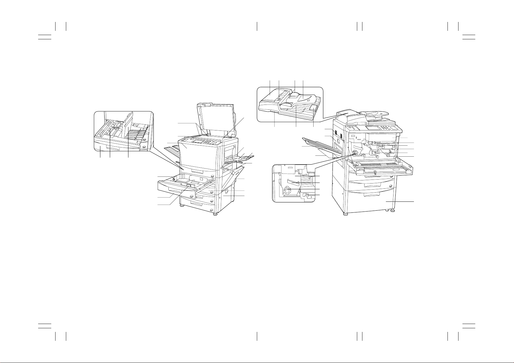
1-3-1 Part names and their functions
• 42 ppm copier
^
&*(
1
2
90 !
#
@
$
7
3
5
8
%
¨
)⁄¤
64
fi
Á
Á
‹
›
„
´
‰
ˇ
fl
°
‚
‡
·
Œ
ˆ
Figure 1-3-1-a
1 Contact platen
2 Original size indictor lines
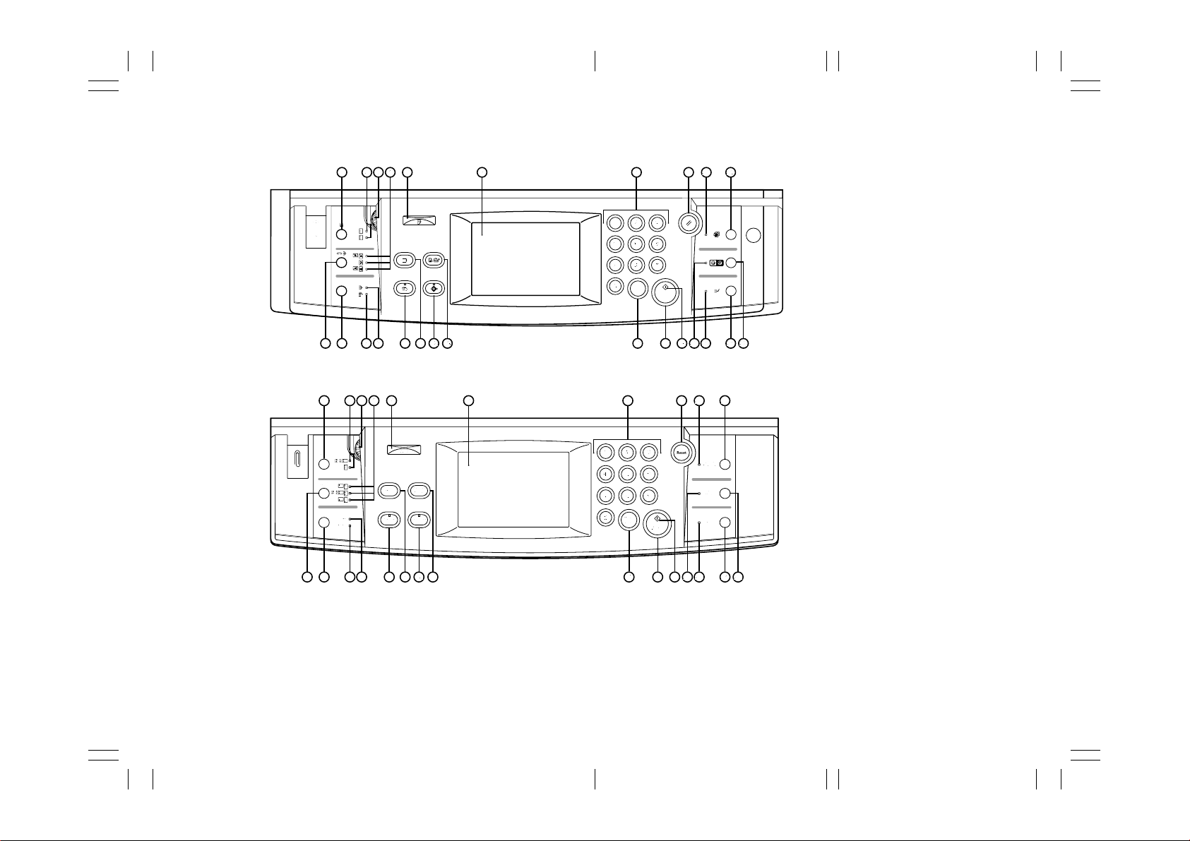
3 Operation panel
4 Bypass table
5 Insert guide
6 Support guide
7 Front cover
8 Right cover
9 Duplex unit
0 Re-feeding section
! Duplex unit cover
@ Upper drawer
# Length guide tab
$ Width guide tab
% Lower drawer
^ DF original reversing cover
& Original set indicator
* Original insertion guides
( Original table
) DF opening/closing lever
⁄ Original ejection cover
¤ Paper ejection guide
‹ Main switch
› Left cover
fi Copy tray*
fl Toner cartridge
‡ Toner cartridge release lever
° Image formation unit release button
· Image formation unit handle
‚ Paper transfer unit release lever
1
ΠPaper feed section knob
„ Fixing unit
´ Fixing unit handle
‰ Fixing knob
ˇ Fixing unit release lever
Á Handles for transport
¨ Paper feed desk*
ˆ Large paper deck*
*1: Optional for 120 V specifications.
*2: Optional.
2
2
1-3-1
E
A
1-3-1 (2A3/4/E) 1/1/32, 21:011
A A
E E
EA
2AD (MCA)
E
A
Page 24
AA A
EE E
A
A
E
2A3/4
• 52 ppm copier
E
¤⁄)(
Î
6
fl
‡
°
Î
‹›fi
·
‚
Œ
„
´
‰
0
7
1
2
3
5
4
8
ˇ
^
*
9
!
&
@
$
#
Ø
∏
Å
Í
ˆ
Á
¨
%
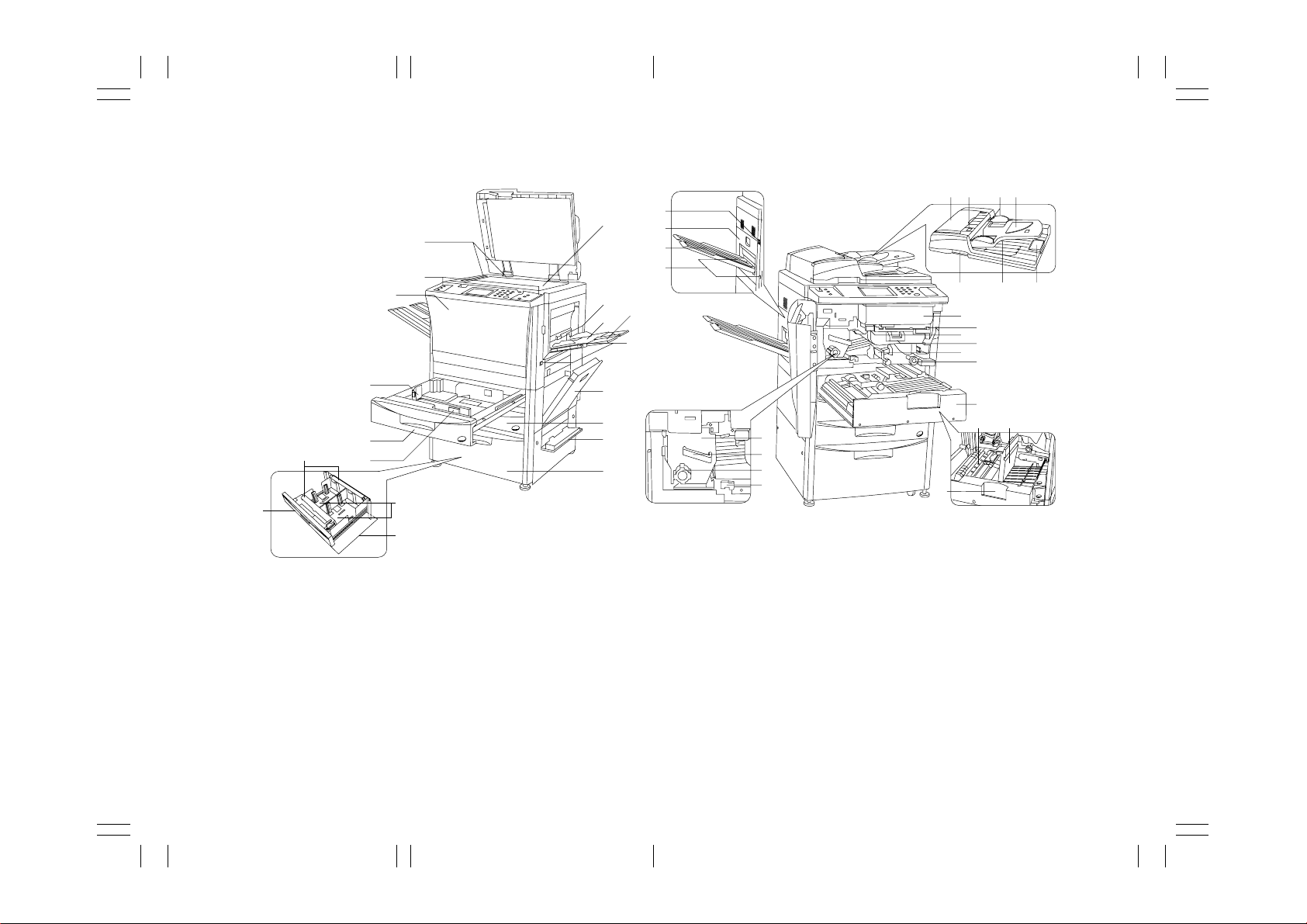
Figure 1-3-1-b
1 Contact platen
2 Original size indictor lines
3 Operation panel
4 Bypass table
5 Insert guide
6 Support guide
7 Front cover
8 Right cover
9 Upper drawer
0 Length guide tab
! Width guide tab
@ Lower drawer
# Large paper deck
$ Deck side cover
% Drawer
^ Deck front cover
& Lifts
* Paper side guides
( DF original reversing cover
) Original set indicator
⁄ Original insertion guides
¤ Original table
‹ DF opening/closing lever
› Original ejection cover
fi Paper ejection guide
fl Main switch
‡ Left cover
° Copy tray*
· Toner cartridge
‚ Toner cartridge release lever
ΠImage formation unit release button
„ Image formation unit handle
´ Paper transfer unit release lever
‰ Paper feed section knob
ˇ Duplex unit
Á Re-feeding section
¨ Duplex unit cover
ˆ Duplex unit handle
Ø Fixing unit
∏ Fixing unit handle
Å Fixing knob
Í Fixing unit release lever
Î Handles for transport
* Optional for 120 V specifications.
1-3-2
E
A
1-3-1 (2A3/4/E) 1/1/32, 21:012
AA A
EE E
2AD (MCA)
E
A
Page 25
A A
E E
A
EA
A
E
2A3/4
Metric
1 Punch mode key
2 Punch mode indicator
3 Staple sort mode key
4 Staple sort mode indicator
5 Sorter mode key
6 Sort mode indicator
7 Group mode indicator
8 Brightness adjustment control
9 Data indicator
0 Program key
! Manual key
@ Add job key
# Copier/printer switching key
$ Touch panel
% Numeric keys
^ Stop/clear key
& Print key
* Print indicator
( Reset key
Inch
) Auto selection key
⁄ Auto selection indicator
¤ Energy saver key
‹ Energy saver indicator
› Interrupt key
fi Interrupt indicator
E
Figure 1-3-2 Operation panel
1-3-3
E
A
1-3-1 (2A3/4/E) 1/1/32, 21:013
A A
E E
EA
2AD (MCA)
E
A
Page 26
AA A
EE E
A
A
E
2A3/4
E
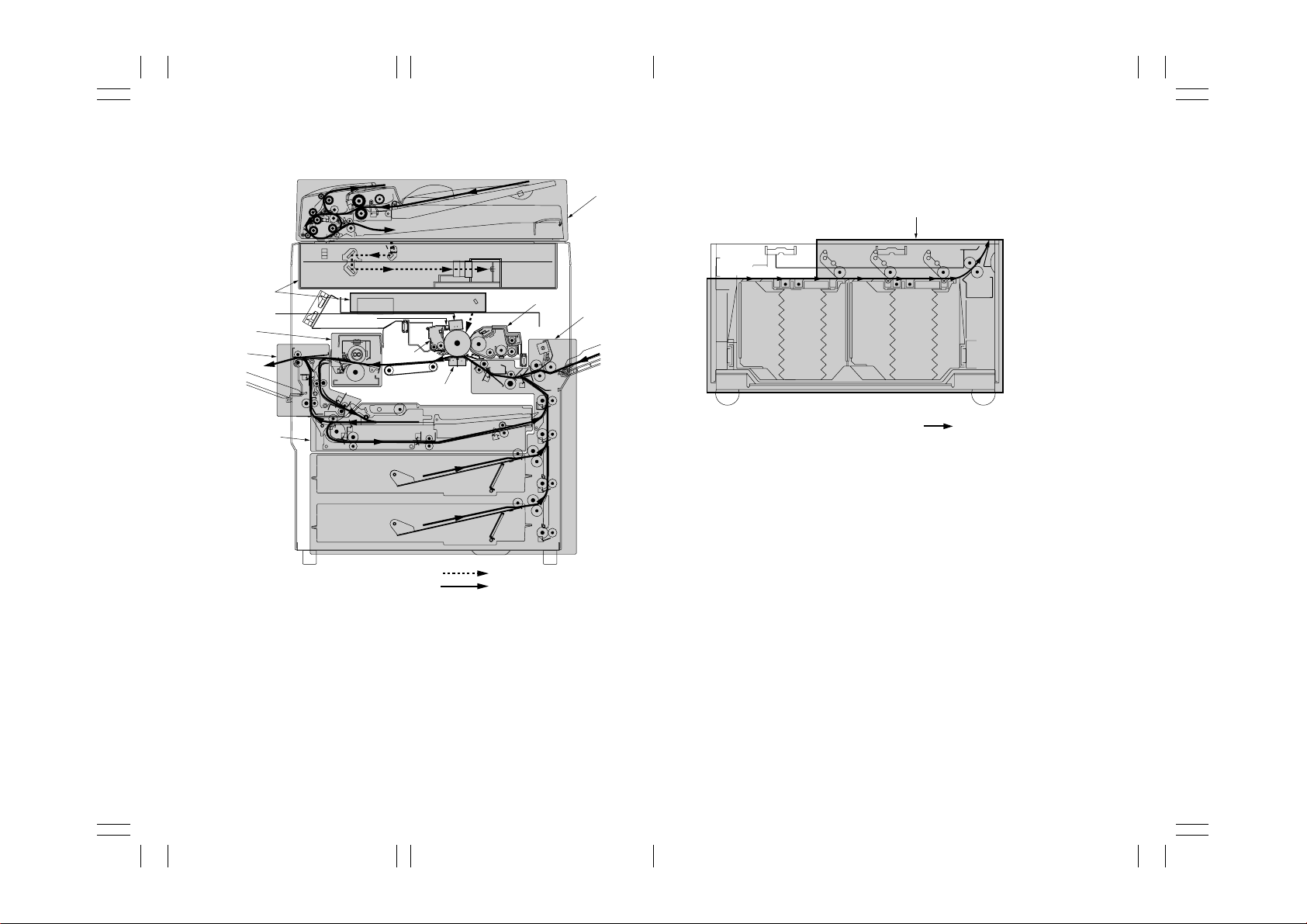
1-3-2 Machine cross section
9
8
3
2
7
!
4
1
6
Large paper deck
(page 1-3-67)
5
0
Figure 1-3-4 Machine cross section—Large paper deck
(42 ppm: optional/52 ppm: standard)
Paper path
Light path
Paper and original path
Figure 1-3-3 Machine cross section—copier and SRDF
1 Paper feed section (page 1-3-8)
2 Main charging section (page 1-3-16)
3 Optical section (page 1-3-19)
4 Developing section (page 1-3-25)
5 Transfer and separation section (page 1-3-36)
6 Cleaning section (page 1-3-40)
7 Charge erasing section (page 1-3-41)
8 Fixing section (page 1-3-43)
9 Feedshift and eject section (page 1-3-49)
0 Duplex section (page 1-3-51)
! SRDF (page 1-3-57)
1-3-4
E
A
1-3-1 (2A3/4/E) 1/1/32, 21:014
AA A
EE E
2AD (MCA)
E
A
Page 27
A A
E E
A
EA
A
E
E
2A3/4
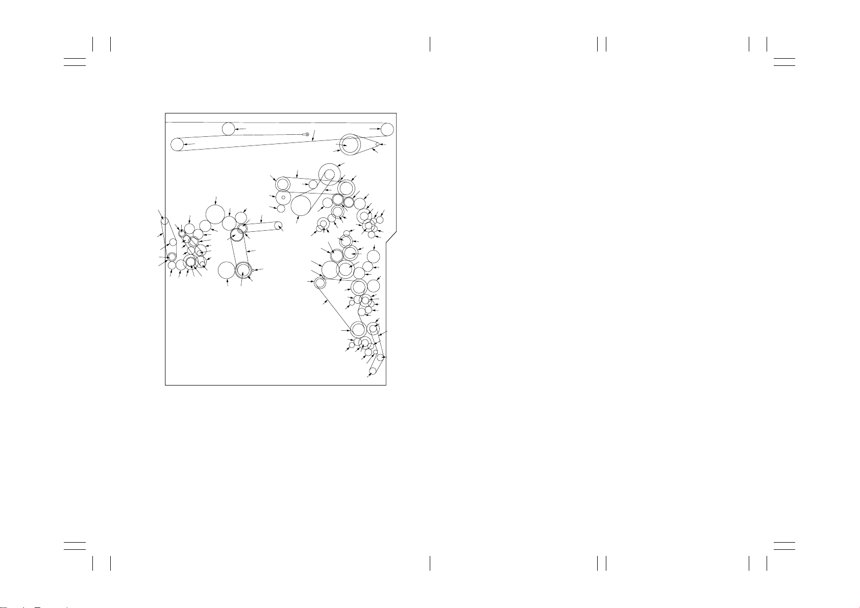
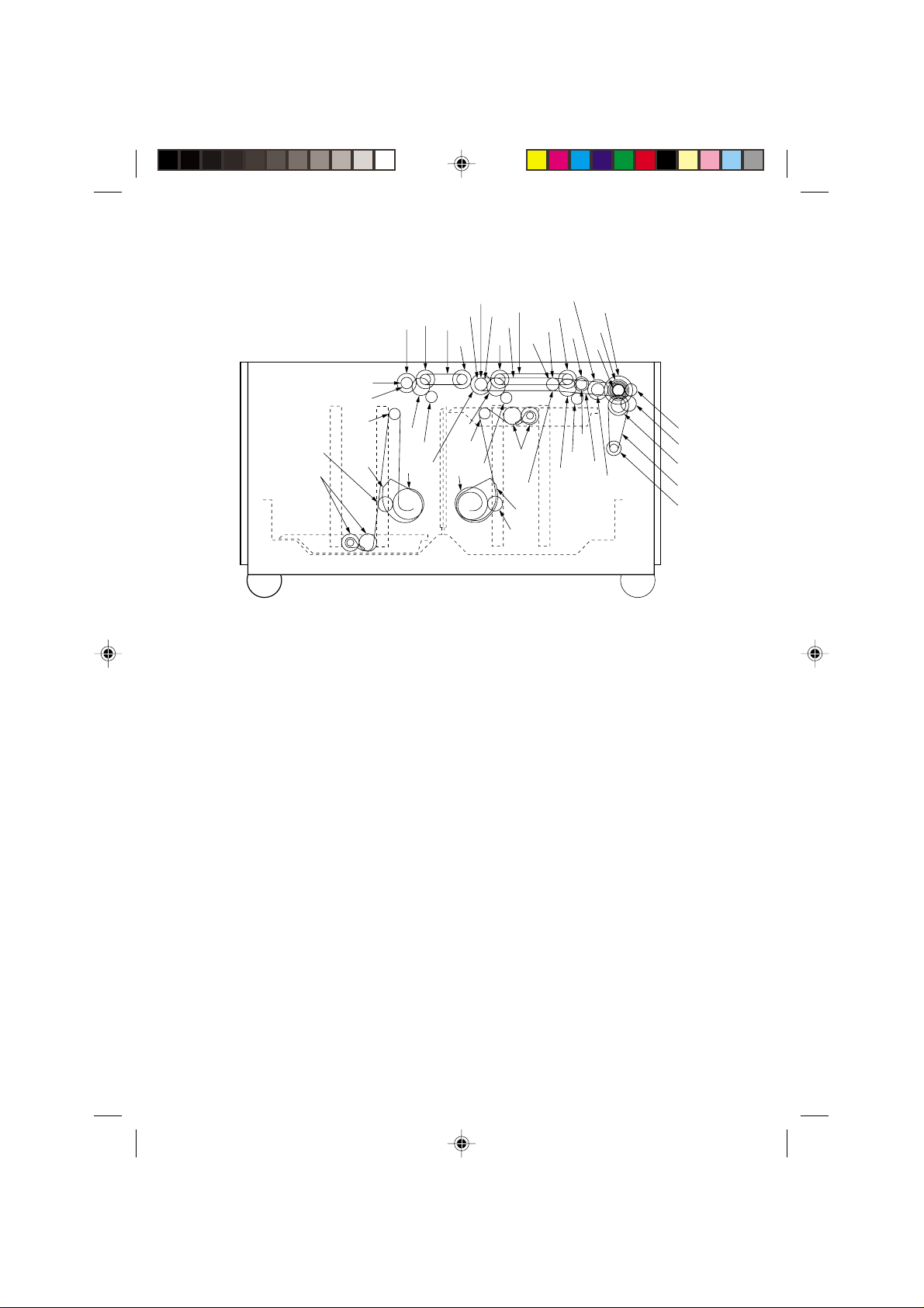
1-3-3 Drive system
7
6
5
3
9
@
0
“
*
‚
·
Î
7
1
8
$
%
^&
ˆ
„
Œ
‰
˝
Ò
Ï
Ú
◊
Â
¯
As viewed from the machine front
! Gear 35/29
@ Developing drive gear
# Gear 31
$ Gear 24
% Gear 20
^ Registration clutch gear
& Upper registration roller gear
* Lower registration roller gear
( Gear 39/25
) Gear 30
8
3
4
2
(
)
⁄
¤
°
!
#
‡
‹
Ø
fi
›
fl
¨
Í
ˇ
Á
´
Å
Ó
∏
Ô
¸
˛
Ç
¡
™
£
˘
ı
˜
¢
¿
∞
§
⁄ Gear 37
¤ Gear 20
‹ Bypass paper feed clutch gear
› Gear 18
fi Gear 16
fl Lower bypass paper feed pulley gear
‡ Gear 16
° Bypass forwarding pulley gear
· paper feed motor gear
‚ Gear 55/45
ΠFeed clutch 5 gear
„ Gear 30
´ Feed clutch 4 gear
‰ Gear 47
ˇ Gear 40
Á Gear 28
¨ Gear 34
ˆ Lower feed roller gear
Ø Upper feed roller gear
∏ Gear 30
Å Gear 28
Í Feed clutch 1 gear
Î Idle pulley 38/23
Ï Paper feed drive belt
˝ Idle pulley 31/42
Ó Feed clutch 2 gear
Ô Upper paper feed clutch gear
Upper paper feed pulley gear
Ò Gear 21
Ú Forwarding pulley gear
¸ Gear16
˛ Lower paper feed pulley gear
Ç Paper feed tension pulley
◊ Idle pulley 31/42
ı Lower paper feed clutch gear
˜ Upper paper feed pulley gear
 Gear 21
¯ Forwarding pulley gear
˘ Gear 16
¿ Lower paper feed pulley gear
¡ Feed clutch 3 gear
™ Feed roller 3 pulley
£ Feed drive belt
¢ Feed idle pulley
∞ Tension pulley 10
§ Feed roller 4 pulley
¶ Paper conveying motor gear
• Idle gear 43
ª Duplex unit input gear
º Pulley 63/32
œ Paper conveying drive belt
∑ Pulley 36/32
® Idle gear 36/36
† Idle gear 30
¥ Gear 26
ø Paper conveying roller
π Paper conveying belt
“ Paper conveying pulley
‘ Fixing drive gear
« Idle gear 30
å Idle gear 26
ß Idle gear 26
∂ Gear 19
ƒ Pulley 22
© Gear 19
˙ Feedshift drive belt
∆ Tension pulley 22
˚ Pulley 22
¬ Gear 20/28
… Idle gear 29
Ω Idle gear 30
≈ One-way gear
ç Idle gear 20
√ Eject speed switching clutch gear
∫ Gear 26
µ Idle gear 26
≤ Idle gear 20
≥ Gear 23
÷ Pulley 28
` Eject drive belt
1 Tension pulley 28
2 Eject roller pulley
3 Scanner motor pulley
4 Scanner drive belt
5 Scanner drive pulley
6 Scanner wire drum
7 Scanner wire
8 Scanner wire pulley
8
2
`
1
÷
≥
ß
∂ƒ
©
˙
ç
√
≈∫
≤
µ
1 Drive motor gear
2 Idle pulley 63/35
3 Cleaning drive belt
4 Idle pulley 40/38
5 Blade thrust gear
6 Cleaning spiral gear
7 Idle pulley 80/26
8 Drum drive belt
9 Drum drive tension pulley
0 Drum drive pulley
8
4
‘
®
«
å
¬
∑
…
∆
Ω
˚
ªº
5
6
†
π
ø
¥
œ
¶
•
Figure 1-3-5 Drive system—copier
1-3-5
E
A
A A
E E
EA
1-3-1 (2A3/4/E) 1/1/32, 21:025
2AD (MCA)
E
A
Page 28
AA A
6
95
43
!
@
0
*
%
&
$
2
8
7
1
^
#
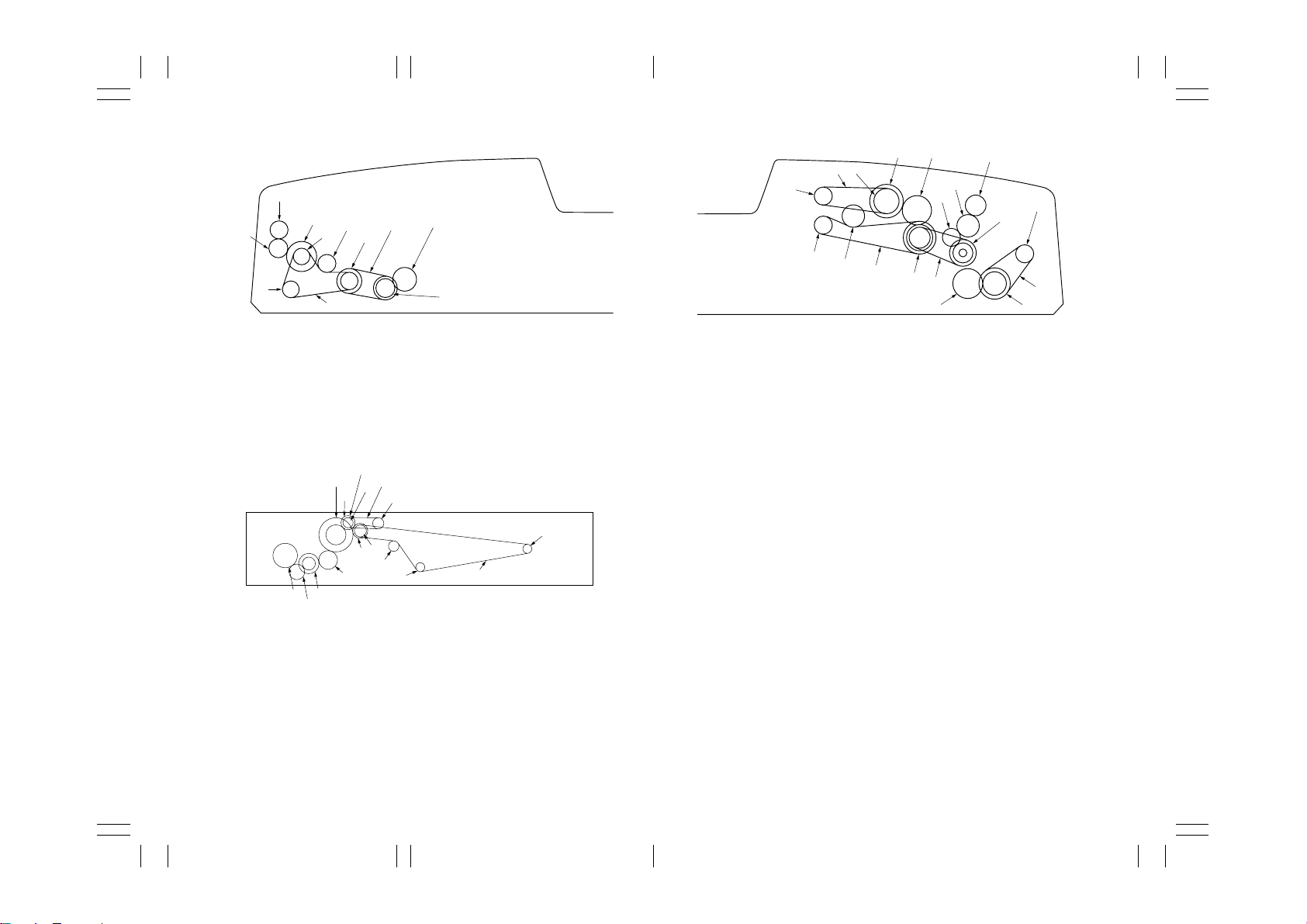
As viewed from machine rear
EE E
A
A
E
2A3/4
E
8
6
7
5
9
1
4
!
Figure 1-3-6 Drive system—SRDF (inside front of machine)
1 Lower original conveying pulley 25/18 7 Joint gear 14
2 Gear 18/25 8 JAM release gear 14
3 Eject gear 18 9 Tension pulley
4 Middle original conveying pulley 18 0 Eject drive belt
5 Upper original conveying pulley 18 ! Conveying drive belt 2
6 JAM release gear 24
0
1
6
7
8
0
9
3
2
As viewed from machine front
Figure 1-3-7 Drive system—SRDF (inside rear of machine)
1 Original feed motor pulley 0 DF registration pulley 28/18
2 Pulley 35/22/22 ! Idle gear 15
3 Idle gear 26 @ Idle gear 20
4 Original feed clutch gear # Switchback gear 18
5 DF original feed pulley 28 $ DF registration drive belt
6 DF forwarding pulley 20 % Gear 22/35
7 Tension pulley ^ Original conveying motor pulley
8 Original feed drive belt & Gear 28
9 DF forwarding belt * Original conveying drive belt 1
^
@
!
$
2
3
5
4
Figure 1-3-8 Drive system—Duplex section
1 Duplex joint gear 9 Forwarding pulley 27
2 Gear 28 0 Gear 18
3 Duplex registration gear 20/30 ! Gear 26
4 Gear 26 @ Paper conveying pulley 40
5 Switchback roller gear # Paper conveying drive belt
E
6 Forwarding drive gear 18 $ Paper conveying tension pulley
7 Pulley 22 % Paper conveying pulley 20
8 Forwarding belt ^ Paper conveying pulley 20
1-3-6
%
#
As viewed from machine front
E
A
AA A
EE E
1-3-1 (2A3/4/E) 1/1/32, 21:026
2AD (MCA)
A
Page 29
2A3/4
9
(
5
%
3
$
)
$
$
*
5
%
5
%
&
⁄
¤
›
$
fi
#
4
fi
$
¤
⁄
#
^
‹
&
As viewed from machine front
Figure 1-3-9 Drive system—Large paper deck
(42 ppm: optional/52 ppm: standard)
1 Belt 180-6
2 Paper feed clutch 1
3 Paper feed clutch 2
4 Paper conveying clutch
5 Gear 20
6 Gear 26
7 Gear 50-20
8 Gear 35-1-20
9 Pulley 18
0 Gear 43-20
! Pulley S2M-18
@ Gear 16
# Roller 0.8-20
$ Pulley 20, gear 32
% One-way drum
^ Pulley 18-OW
& Pulse gear
* Belt 258
( Belt 234
) Belt 144
⁄ Gear 1.0-24
¤ Lift pulley
‹ Left lift belt assembly
› Right lift belt assembly
fi Paper deck motor gear
fl Pulley 16
$
$
2
6
#
@
8
fl
(
7
5
5
6
0
1
!
1-3-2 (2A3/4/E) 1/1/32, 2:397
1-3-7
Page 30
2A3/4
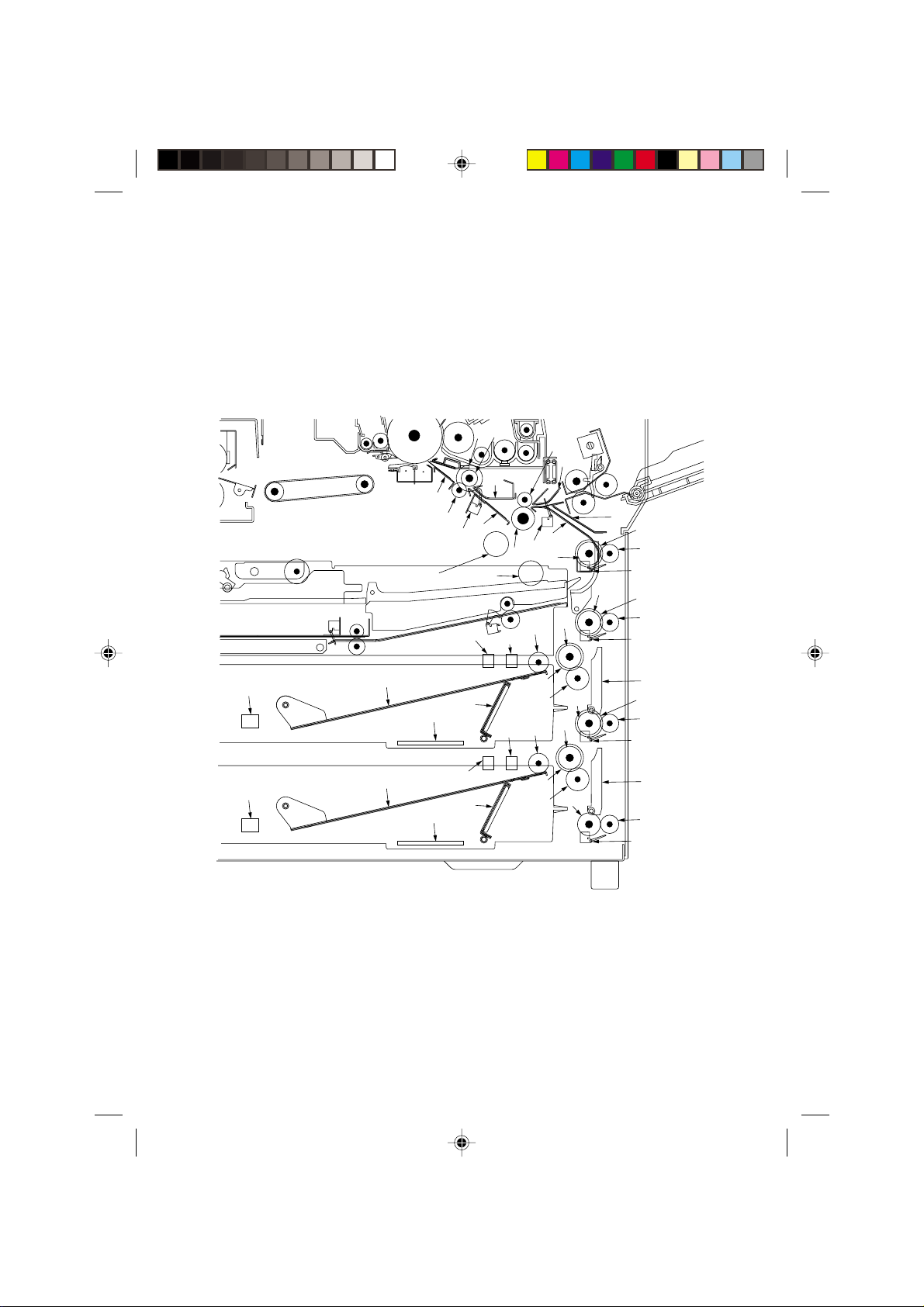
1-3-4 Mechanical construction
(1) Paper feed section
The paper section consists of the primary feed and secondary feed subsections.
Primary feed conveys paper from the upper drawer, lower drawer or bypass table to the
upper and lower registration rollers, at which point secondary feed takes place and the
paper travels to the transfer section in sync with the printing timing.
(1-1) Paper feed from the drawers
$
·
4
6
^
*
°
%
Ø
„
&
‡
‚
5
ˆ
1
8
9
2
0
7
›
#
‰
fi
#
ˇ
∏
Å
Figure 1-3-10 Drawer paper feed and secondary paper feed sections
1-3-8
)
)
Í
Î
⁄
´
⁄
Œ
1
¤
3
‹
3
2
@
!
(
fl
#
Á
(
#
¨
1-3-2 (2A3/4/E) 1/1/32, 2:398
Page 31

2A3/4
1 Forwarding pulley
2 Upper paper feed pulley
3 Lower paper feed pulley
4 Upper feed roller
5 Lower feed roller
6 Upper feed guide plate
7 Middle feed guide plate
8 Lower feed guide plate
9 Feed roller 1
0 Feed roller 2
! Feed roller 3
@ Feed roller 4
# Feed pulley
$ Upper registration roller
% Lower registration roller
^ Upper registration guide
& Lower registration guide
* Lower pre-transfer guide
( Feed guide
) Drawer lift
⁄ Lift operation plate
¤ Upper paper feed clutch (PFCL-U)
‹ Lower paper feed clutch (PFCL-L)
› Feed clutch 1 (FCL1)
fi Feed clutch 2 (FCL2)
fl Feed clutch 3 (FCL3)
‡ Feed clutch 4 (FCL4)
° Feed clutch 5 (FCL5)
· Registration clutch (RCL)
‚ Upper paper switch (PSW-U)
ΠLower paper switch (PSW-L)
„ Upper lift limit switch (LICSW-U)
´ Lower lift limit switch (LICSW-L)
‰ Paper feed switch 1 (PFSW1)
ˇ Paper feed switch 2 (PFSW2)
Á Paper feed switch 3 (PFSW3)
¨ Paper feed switch 4 (PFSW4)
ˆ Feed switch (FSW)
Ø Registration switch (RSW)
” Upper paper length switch
(PLSW-U)
Å Lower paper length switch
(PLSW-L)
Í*Upper paper width switch
(PWSW-U)
Î*Lower paper width switch
(PWSW-L)
* For inch specifications only.
1-3-2 (2A3/4/E) 1/1/32, 2:399
1-3-9
Page 32

2A3/4
Each drawer consists of a lift driven by the lift motor and other components. Each
drawer can hold up to 550 sheets of paper.
Paper is fed from the drawer by the rotation of the forwarding pulley and upper paper
feed pulley. The lower paper feed pulley prevents multiple sheets from being fed at one
time, via the torque limiter.
CN13-4
CN13-7
CN13-10
CN13-13
CN8-B11
RCL
CN8-B2
CN13-1
CN12-A2
CN8-B9
CN12-A4
CN12-A8
CN15-3
CN15-9
CN15-13
CN12-A10
CN15-4
CN15-10
CN15-14
EPCB
LICSW-U
LICSW-L
RSW
FCL5
FCL4
PSW-U
PSW-L
PFCL
U
PFCL
L
FSW
FCL1
PFSW1
FCL2
PFSW2
FCL3
PFSW3
PFSW4
Figure 1-3-11 Drawer paper feed section block diagram
1-3-10
1-3-2 (2A3/4/E) 1/1/32, 2:3910
Page 33

Image ready
2A3/4
Print key
FCL4
FSW
RSW
FCL5
RCL
PFM
DM
PFCL-U
FCL2
PFSW2
FCL1
PFSW1
Auto copy density control, copy paper: A4/11" × 8
174 ms
250 ms
100 ms
50 ms
163 ms
28 ms
ABC D E F G H J K
58 ms
35 ms
100 ms
74 ms 80 ms
35 ms
1
/2", magnification ratio 100%
Timing chart 1-3-1 Paper feed from the upper drawer
1-3-2 (2A3/4/E) 1/1/32, 2:3911
1-3-11
Page 34

2A3/4
A When the print key is pressed, the paper feed motor (PFM) turns on, and 250 ms later
the drive motor (DM) turns on to start drive for the paper feed section.
B 100 ms after the print key is pressed, the upper paper feed clutch (PFCL-U) turns on,
and the upper and lower paper feed pulleys rotate to start the primary paper feed.
C 50 ms after the upper paper feed clutch (PFCL-U) turns on, feed clutch 2 (FCL2) turns
on, and feed roller 2 rotates.
D 28 ms after the leading edge of the paper turns paper feed switch 2 (PFSW2) on, feed
clutch 1 (FCL1) turns on, and feed roller 1 to rotates.
E 163 ms after paper feed switch 2 (PFSW2) turns on, the upper paper feed clutch (PFCL-
U) turns off.
F 174 ms after the leading edge of the paper turns paper feed switch 1 (PFSW1) on, feed
clutch 4 (FCL4) turns on, and the lower feed roller rotates at high speed to create slack
in the paper before registration.
G 58 ms after the trailing edge of the paper turns paper feed switch 2 (PFSW2) turns off,
feed clutch 2 (FCL2) turns off.
H 35 ms after the leading edge of the paper turns the registration switch (RSW) on, feed
clutches 1 and 4 (FCL1 and FCL4) turn off.
I 74 ms after image ready signal turn on, the registration clutch (RCL) turns on, causing
the upper and lower registration rollers to rotate to start secondary paper feed.
Simultaneously, feed clutch 5 (FCL5) turns on and the lower feed roller rotates at low
speed.
J 100 ms after the trailing edge of the paper turns the feed switch (FSW) off, feed clutch
5 (FCL5) turns off.
K 80 ms after the trailing edge of the paper turns the registration switch (RSW) off, the
registration clutch (RCL) turns off.
1-3-12
1-3-2 (2A3/4/E) 1/1/32, 2:3912
Page 35

(1-2) Paper feed from the bypass table
2A3/4
!
9
7
8
Figure 1-3-12 Bypass paper feed section
1 Bypass table
2 Bypass upper guide
3 Bypass lower guide
4 Bypass stopper
5 Bypass friction plate
6 Bypass forwarding pulley
7 Bypass upper paper feed pulley
8 Bypass lower paper feed pulley
0
2
6
#
5
3
4
9 Bypass paper feed clutch
(BYPPFCL)
0 Bypass solenoid (BYPSOL)
! Bypass paper switch (BYPPSW)
@ Bypass paper length switch
(BYPPLSW)
# Bypass paper width switch
(BYPPWSW)
$ Bypass table extended detection
switch (BYPEDSW)
1
$
@
The bypass table can hold up to 100 sheets of paper at one time.
When the start key is pressed, the bypass solenoid (BYPSOL) turns on, unlocking the
bypass stopper and lowering the bypass forwarding pulley until it comes into contact
with the paper. This conveys paper placed on the bypass table to the bypass upper and
lower paper feed pulleys. The bypass paper feed clutch (BYPPFCL) then turns on,
transmitting the drive motor (DM) drive to these pulleys to start primary paper feed.
The bypass lower paper feed pulley rotates opposite to the paper feed direction so that
the torque limiter prevents multiple sheets from being fed at one time.
1-3-2 (2A3/4/E) 1/1/32, 2:3913
1-3-13
Page 36

2A3/4
CN14-A8
CN14-A4
CN14-A7
CN8-B11
RCL
BYPPSW
BYP
PFCL
BYPSOL
Print key
FSW
RSW
FCL5
RCL
PFM
DM
BYPSOL
BYPPFCL
CN8-B2
CN13-1
CN12-A2
CN8-B9
EPCB
RSW
FCL5
FSW
FCL4
Figure 1-3-13 Bypass paper feed section block diagram
Image ready
115 ms 100 ms65 ms
74 ms 80 ms
250 ms
100 ms
300 ms
90 ms
200 ms
AB C D E G H I J
Auto copy density control, copy paper: A5R/5
Timing chart 1-3-2 Paper feed from the bypass table
1-3-14
1-3-2 (2A3/4/E) 1/1/32, 2:3914
F
1
/2" × 81/2", magnification ratio 25%
Page 37

2A3/4
A When the print key is pressed, the paper feed motor (PFM) turns on, and 250 ms later
the drive motor (DM) turn on to start drive for the paper feed section.
B 100 ms after the print key is pressed, the bypass solenoid (BYPSOL) turns on. The
bypass stopper is then unlocked, and the bypass forwarding pulley lowers to forward the
paper.
C 300 ms after the bypass solenoid (BYPSOL) turns on, the bypass paper feed clutch
(BYPPFCL) turns on, and the upper and lower bypass paper feed pulleys rotate to start
primary paper feed.
D 115 ms after the leading edge of the paper turn the feed switch (FSW) on, feed clutch
5 (FCL5) turns on, and the lower feed roller rotates at low speed to create slack in the
paper before registration.
E 200 ms after the feed switch (FSW) turns on, the bypass paper feed clutch (BYPPFCL)
turns off.
F 90 ms after feed clutch 5 (FCL5) turns on, the bypass solenoid (BYPSOL) turns off.
G 65 ms after the leading edge of the paper turns the registration switch (RSW) on, feed
clutch 5 (FCL 5) turns off.
H 74 ms after the image ready signal turns on, the registration clutch (RCL) turns on, and
the upper and lower registration rollers rotate to start secondary paper feed.
Simultaneously, feed clutch 5 (FCL5) turns on and lower feed roller rotates at low speed.
I 100 ms after the trailing edge of the paper turns the feed switch (FSW) off, feed clutch
5 (FCL5) turns off.
J 80 ms after the trailing edge of the paper turns the registration switch (RSW) off, the
registration clutch (RCL) turns off.
1-3-2 (2A3/4/E) 1/1/32, 2:3915
1-3-15
Page 38

2A3/4
(2) Main charging section
The main charging section consists of the drum and the main charger assembly.
The main charger assembly charges the drum so that a latent image is formed on the
surface, the charger grid ensuring the charge is applied uniformly.
Main charger assembly
Main charger grid
Tungsten wire
Drum
Figure 1-3-14 Main charging section
1-3-16
1-3-2 (2A3/4/E) 1/1/32, 2:3916
Page 39

!
2A3/4
0
3
1
5
Figure 1-3-15 Main charger
1 Main charger front housing
2 Main charger rear housing
3 Main charger front lid
4 Main charger rear lid
5 Main charger shield
CN5-B1
CN5-B13
CN5-B11
CN5-B12
EPCB
24 V DC
MC REM
MC ALM
GRID CONT
6
2
6 Tungsten wire
7 Charger spring
8 Charger terminal
9 Charger pin
0 Main charger grid
! Grid tension plate
CN1-13
CN1-1
CN1-3
CN1-2
TB
HVTPCB
4
9
7
8
MC
Grid
Drum
Figure 1-3-16 Main charging section block diagram
1-3-2 (2A3/4/E) 1/1/32, 2:3917
1-3-17
Page 40

2A3/4
Print key
CFM1
ESW
520 ms
MC REM
PFM
AB C
Auto copy density control, copy paper: A4/11" × 8
360 ms
300 ms
290-30000 ms
1
/2", magnification ratio 100%
Timing chart1-3-3 Main charging
A When the print key is pressed, the paper feed motor (PFM) turns on.
B 520 ms after the paper feed motor (PFM) turns on, main charging (MC REM) starts.
C 300 ms after cooling fan motor 1 (CFM1) turns off, main charging (MC REM) is
completed.
1-3-18
1-3-2 (2A3/4/E) 1/1/32, 2:3918
Page 41

2A3/4
(3) Optical section
The optical section consists of the scanner, mirror frame and image scanning unit for
scanning and the laser scanner unit for printing.
6
4
$
5
1 Scanner
2 Mirror frame
3 Mirror 1
4 Mirror 2
5 Mirror 3
6 Exposure lamp (EL)
7 Reflector
7
2
Figure 1-3-17 Optical section
8
9
1
3
8 Image scanning unit
9 Lens
0 Optical rail
! Laser scanner unit (LSU)
@ CCD PCB (CCDPCB)
# Scanner motor (SM)
$ Scanner home position switch
(SHPSW)
!
0
@
#
1-3-2 (2A3/4/E) 1/1/32, 2:3919
1-3-19
Page 42

2A3/4
Original scanning
The original image is illuminated by the exposure lamp (EL) and scanned by the CCD
PCB (CCDPCB) in the image scanning unit via the three mirrors, the reflected light
being converted to an electrical signal.
The scanner and mirror frame travel to scan on the optical rails on the front and rear of
the machine to scan from side to side. The speed of the mirror frame is half the speed
of the scanner. When the SRDF is used, the scanner and mirror frame stop at the DF
original scanning position to start scanning.
Original
SHPSW
CN4-2
SM
CN2-1–
CN2-6
CN1-1–
CN5-1–
SMPCB INPCB
CN3-1–
CN3-6
CN1-16
CN5-16
CN1-1–
CN1-140
MPCB
CN1-1–
CN1-6
EL
CN2-1
CN7-1–
CN7-13
CN2-4
CN8-1–
LSU
Drum
CCDPCB
CN11-1–
CN11-11
CN8-5
CN12-1–
CN12-7
CN9-1–
CN9-4
CN1-1–
Figure 1-3-18 Optical section block diagram
1-3-20
1-3-2 (2A3/4/E) 1/1/32, 2:3920
CN1-140
EPCB
CN7-1–
CN7-2
Page 43

2A3/4
Print key
Fwd. rotation
SM
Rev. rotation
SHPSW
FVSYNC signal
410 P
414 P
9921 P
AB
Manual copy density control, copy paper: A3/11" × 17", magnification ratio 100%
CD
110 P
Timing chart 1-3-4 Scanner operation
A When the print key is pressed, the scanner motor (SM) reverses for 410 pulses and
then rotates forward.
B 414 pulses after the scanner motor rotates forward, the FVSYNC signal turns on for
9921 pulses for scanning.
C The scanner motor (SM) reverses to return the scanner to the home position.
D 110 pulses after the scanner home position switch (SHPSW) turns on, the scanner
motor (SM) turns off, and the scanner stops at its home position.
1-3-2 (2A3/4/E) 1/1/32, 2:3921
1-3-21
Page 44

2A3/4
Image printing
The image data scanned by the CCD PCB (CCDPCB) is processed on the main PCB
(MPCB) and transmitted as image printing data to the laser scanner unit (LSU). By
repeatedly turning the laser on and off, the laser scanner unit forms a latent image on
the drum surface.
• Laser scanner unit
Collimator lenses
Laser diodes (LD)
LD control PCB
BD sensor mirror
Oject mirror
Beam spritter
Lens 1
Lens 3
Lens 2
Polygon mirror
Polygon motor (PM)
Lens 4
Figure 1-3-19 Laser scanner unit (1)
1-3-22
1-3-2 (2A3/4/E) 1/1/32, 2:3922
BD sensor
Motor drive PCB
Cylindrical correcting lens
Page 45

2A3/4
1
2
6
5
7
3
5
8
9
0
1 Laser diodes: Generate the laser beams that form the latent image on the drum.
2 Collimator lenses: Collimate the diffused laser beams emitted from the laser diodes into
cylindrical beams.
3 Beam splitter: Refracts the laser beam emitted from one of the laser diodes so that it
becomes parallel to the other laser beam, and sends those two beams to lens 1.
4 Polygon mirror: 6-faced mirror that rotates at approximately 29527 rpm. Each face
reflects the laser beams toward the drum in the horizontal (main) scan direction. The
motion of the beams across the drum forms one scan line.
5 Lenses 1, 2, 3 and 4: Maintain scanning speed across the drum and beam diameters
constant. These lenses also correct the vertical alignment of the polygon mirror so that
the focal plane of the laser beams are always on the drum.
6 Object mirror: Reflects the laser beams onto the drum surface.
7 BD sensor mirror: Directs a laser beam to the BD sensor to generate the horizontal sync
signal.
8 Cylindrical correcting lens: Corrects for the deviation of the laser beam reflected by the
BD sensor mirror.
9 BD sensor: Detects the laser beam reflected by BD sensor mirror, and sends the
detection signal to the main PCB (MPCB). The main PCB (MPCB) uses this signal to
determine the horizontal scanning signal timing.
0 Glass dust filter: Prevents dust from entering the unit.
Drum
Figure 1-3-20 Laser scanner unit (2)
5
4
1-3-2 (2A3/4/E) 1/1/32, 2:3923
1-3-23
Page 46

2A3/4
The dimensions of the laser beam are as shown in Figure 1-3-19.
70 µm
65 µm
Figure 1-3-21
Scanning in the main direction is provided by the rotating polygon mirror, while scanning
in the auxiliary direction is provided by the rotating drum, forming a static latent image
on the drum.
The static latent image of the letter “A”, for example, is formed on the drum surface as
shown in Figure 1-3-22. Electrical charge is dissipated on the area of the drum surface
irradiated by the laser.
The focal point of the laser beam is moved line by line, and adjacent lines slightly
overlap each other.
1-3-24
1-3-2 (2A3/4/E) 1/1/32, 2:3924
Main
scanning
direction
Auxilary
scanning
direction
: laser beam is on
Figure 1-3-22
Page 47

(4) Developing section
The developing section consists of the developing unit and the toner recycling
assembly.
2A3/4
Developing unit
Toner sub hopper
Figure 1-3-23 Developing section
The developing unit consists of the developing roller where a magnetic brush is formed,
the doctor blade and the developing spirals that agitate the developer.
The toner recycling assembly consists of the toner main and sub-hoppers. In t he main
hopper new toner from the toner cartridge is mixed with residual toner recovered from
the cleaning section. The mixture is conveyed by the sub-hopper to the developing unit.
The toner level detection sensor (TLDS) checks whether or not toner remains in the
main hopper.
1-3-2 (2A3/4/E) 1/1/32, 2:3925
1-3-25
Page 48

2A3/4
Toner cartridge
Toner level sensor
Toner recycle paddle A
Toner cartridge paddle
Toner hopper lockup sensor
Toner cartridge spiral
Toner recycle paddle B
Toner recycle spiral
Cleaning unit
Cleaning spiral
Toner feed motor
Toner main hopper
Toner recycle motor
1-3-26
1-3-2 (2A3/4/E) 1/1/32, 2:3926
Main hopper spiral
Toner sub hopper
Sub hopper spiral
Figure 1-3-24 Toner recycling
Developing unit
Toner flow
Page 49

2A3/4
S2
N3
S1
N1
N2
43.5°
59°
85.5°
74.5°
Magnetic poles on the developing roller
Formation of magnetic brush
The developing roller consists of a magnet roller with five poles and a sleeve roller.
Rotation of the sleeve roller around the magnet roller entrains developer, which in turn
forms a magnetic brush at pole N1 on the magnet roller. The height of the magnet brush
is regulated by the doctor blade; the developing result is affected by the position of the
poles on the magnet roller and the position of the doctor blade.
A developing bias voltage generated by the high-voltage transformer (HVTPCB) is
applied to the developing roller to provide image contrast.
4
A
2
5
1
A: Distances beteen the doctor blade and
developing roller: 0.53 ± 0.05 mm
Figure 1-3-25 Forming a magnetic brush
1 Developing unit housing
2 Developing roller
3 Toner sensor (TNS)
4 Doctor blade
6
7
3
5 Developing spiral A
6 Developing spiral B
7 Developing spiral C
N1: 830
N2: 630
N3: 450
S1: 860
S2: 700
× 10
× 10
× 10
× 10
× 10
–4
T
–4
T
–4
T
–4
T
–4
T
1-3-2 (2A3/4/E) 1/1/32, 2:3927
1-3-27
Page 50

2A3/4
CN2-A5
CN2-A6
CN2-A7
CN2-A8
CN2-B3
CN2-A10
CN2-B11
CN2-B9
CN5-B10
CN5-B8 CN1-6
CN5-B1 CN1-13
EPCB
TFM–
TFM+
TRM–
TRM+
TLDS
TLS
TNS SIG
TNS CONT
DB REM
DB CONT
24 V DC
TRM
CN1-4
HVTPCB
TFM
TNS
CN2
DB
Figure 1-3-26 Developing section block diagram
Toner density is detected by the toner sensor (TNS).
The sensor section of the toner sensor detects the ratio of toner to carrier in the
developer near it and converts it into a voltage. As more toner is used, the ratio of toner
to carrier decreases, increasing the toner sensor output voltage.
When the ratio drops below the specified value, the increase in toner sensor output
voltage triggers toner replenishing. When toner is added and the ratio of toner to carrier
returns to normal, the toner sensor output voltage drops to the point where toner
replenishing stops.
1-3-28
1-3-2 (2A3/4/E) 1/1/32, 2:3928
Page 51

2A3/4
Toner density control
Toner density control is conducted using the TARGET value as the reference which is
the toner sensor initial output value set by maintenance item U130 when developer is
loaded for the first time.
Toner being replenished message
Toner sensor
output voltage (V)
Toner empty detection
level
Toner empty reset level
Toner feed start level
(TARGET by U130)
Toner feed stop level
Toner request message
(Toner cartridge to be replaced.)
Aging:
1 min: during copying
Copying
AB CD EF G H IJ
Figure 1-3-27 Toner density control
A When the toner sensor output voltage exceeds the toner feed start level, the toner feed
motor (TFM) and the toner recycle motor (TRM) operate intermittently—on for 0.5 s and
off for 1.5 s, and on for 1.0 s and off for 1.0 s, respectively—to replenish toner.
B As toner is replenished, the toner sensor output voltage drops below the toner feed stop
level and replenishing stops.
C Both the toner feed motor (TFM) and toner recycle motor (TRM) operate intermittently—
on for 0.5 s and off for 0.5 s—to replenish toner until the toner sensor output voltage
reaches the toner empty reset level after exceeding the toner feed start level.
D The toner feed motor (TFM) and toner recycle motor (TRM) operate intermittently—on
for 1.0 s and off for 1.0 s, and on for 1.5 s and off for 0.5 s, respectively—to replenish
toner until the toner sensor output voltage reaches the toner empty detection level after
exceeding the toner feed reset level
E When the toner sensor output voltage exceeds the toner empty detection level after
toner replenishing is carried out, the toner being replenished message appears. Both the
toner feed motor (TFM) and toner recycle motor (TRM) then operate intermittently—on
for 1.5 s and off for 0.5 s—for 1 min. for aging. If the voltage fails to fall to the toner empty
reset level, the toner request message appears.
1-3-2 (2A3/4/E) 1/1/32, 2:3929
1-3-29
Page 52

2A3/4
F When the toner sensor output voltage drops to the toner empty reset level, the toner
being replenished message disappears, and both the toner feed motor (TFM) and toner
recycle motor (TRM) operates intermittently—on for 0.5 s and off for 0.5 s—to replenish
toner.
G When toner is replenished, the toner sensor output voltage drops below the toner feed
stop level and replenishing stops.
H After the toner cartridge is replaced, both the toner feed motor (TFM) and toner recycle
motor (TRM) operate intermittently—on for 1.5 s and off for 0.5 s—to replenish toner.
I When the toner sensor output voltage drops to the toner feed stop level, the toner request
message disappears. Both the toner feed motor (TFM) and toner recycle motor (TRM)
then operate intermittently—on for 1.0 s and off for 1.0 s—to replenish toner.
J When toner is replenished, the toner sensor output voltage drops to the toner feed stop
level and replenishing stops.
1-3-30
1-3-2 (2A3/4/E) 1/1/32, 2:3930
Page 53

2A3/4
(g
)
Correcting toner feed start level
The toner feed start level is corrected based on the absolute humidity and the drive time
so that toner density becomes proper depending on the change of the humidity and the
drive time.
• Correction based on the absolute humidity
Correction at the toner
feed start level (V)
0.74
B
0
– 0.16
0 3.09 10.8
C
A
Maintenance item U130 performed.
35.9
D
Absolute humidity
/m
3
Figure 1-3-28 Correction based on the absolute humidity
A When maintenance item U130 is carried out for initial developer setting, the toner sensor
control voltage (CONTROL) is set so that the toner sensor outputs 2.01 V when the
absolute humidity is 10.8 g/m3.
B When the absolute humidity is between 0 and 10.8 g/m3, the toner feed start level is
decreased with the absolute humidity so that the toner sensor output voltage drops.
C When the absolute humidity is between 10.8 and 35.9 g/m3, the toner feed start level is
increased with the absolute humidity so that the toner sensor output voltage rises.
D When the absolute humidity exceeds 35.9 g/m3, the toner feed start level is increased
by 0.74 V to regulate the toner sensor output.
1-3-2 (2A3/4/E) 1/1/32, 2:3931
1-3-31
Page 54

2A3/4
Computing the absolute humidity
The external humidity sensor (EHUMSENS) and external temperature thermistor
(ETTH) are located on the humidity sensor PCB (HUMPCB). The external humidity
sensor (EHUMSENS) converts the relative humidity detected by the humidity sensing
element into a voltage and sends it to the engine PCB (EPCB). The main PCB
(MPCB)computes the absolute humidity based on this EHUMSENS signal and the
temperature (ETTH signal) detected by the external temperature thermistor (ETTH).
EPCB
HUMPCB
Humidity sensing element
ETTH
43ETTH
GND
2 EHUMSENS
CN5-A1
CN5-A2
CN5-A3
EHUMSENS
15 V
CN5-A4
Figure 1-3-29 Absolute humidity computation block diagram
1-3-32
1-3-2 (2A3/4/E) 1/1/32, 2:3932
Page 55

2A3/4
• Correction based on the total drive motor time
The toner feed start level is also corrected based on the total time the drive motor (DM)
has been on from execution of maintenance item U130, so that the toner sensor output
is regulated properly.
Correction at the toner
feed start level (V)
0.76
0.46
0.36
0.24
D
C
E
B
0
10 30 50 150 Drive time (h)
A
Maintenance item U130 performed.
Figure 1-3-30 Correction based on the total drive motor time
A When maintenance item U130 is carried out for initial developer setting, the total drive
motor time is cleared and the correction for the toner feed start level is reset to 0.
B When the total drive time reaches 10 hours, the toner feed start level is corrected with
a constant value of 0.24 V.
C When the total drive time reaches 30 hours, the toner feed start level is corrected with
a constant value of 0.36 V.
D When the total drive time reaches 50 hours, the toner feed start level is corrected with
a constant value of 0.46 V.
E When the total drive time exceeds 150 hours, the toner feed start level is corrected with
a constant value of 0.76 V.
1-3-2 (2A3/4/E) 1/1/32, 2:3933
1-3-33
Page 56

2A3/4
Toner level detection
The toner level in the toner main hopper is monitored by the toner level detection sensor
(TLDS). It converts the presence or absence of toner in the toner main hopper into a
voltage and sends it to the main PCB (MPCB), which triggers a message to request the
toner cartridge to be replaced before the recycled toner ratio in the toner main hopper
reaches a significant level.
Toner feed motor (TFM)
4.5 V
Toner level detection
sensor output voltage
0.5 V
Toner request message Toner empty detection
Toner cartridge to be
replaced.
Toner empty detection
TFM: on
ignored.
10 s
reactivated.
U 130 performed.
Toner empty
detection ignored.
1 min. 5 min.
10 s
Toner empty detection
reactivated.
10 s
AB C D
Figure 1-3-31 Toner level detection
A When the toner level detection sensor (TLDS) output voltage drops below 0.5 V while
the toner feed motor (TFM) is on, the toner motor drive time starts to be counted.
B If the toner level detection sensor (TLDS) output voltage remains below 0.5 V for 10 s,
the toner request message appears.
Note: When the toner request message is displayed under these conditions, the
available copy mode and the number of copies that can be made are
restricted as set in maintenance item U258 (see page 3-2-74).
C Toner empty detection is ignored for 1 min. (the toner feed motor on time) after the toner
cartridge has been replaced. If the toner level detection sensor (TLDS) output remains
at 4.5 V or above for 10 s, toner empty detection is reactivated.
D Toner empty detection is ignored for 5 min. (the toner feed motor on time) after
maintenance item U130 has been performed for developer initial setting. If the toner level
detection sensor (TLDS) output remains at 4.5 V or above for 10 s, toner empty detection
is reactivated.
1-3-34
1-3-2 (2A3/4/E) 1/1/32, 2:3934
Page 57

2A3/4
Toner hopper lockup detection
The amount of recycled toner in the toner main hopper is monitored by the toner hopper
lockup sensor (TLS). It converts the presence or absence of toner in the toner main
hopper into a voltage and sends it to the main PCB, which prevents toner main hopper
lockup as the amount of the recycled toner in the hopper increases.
Toner feed start level
Toner feed stop level
Toner recycle motor
1 min
Toner hopper lockup
sensor output voltage (V)
4.5 V
0.5 V
AB C D
Figure 1-3-32 Toner hopper lockup detection
A When the toner hopper lockup sensor (TLS) output voltage is below 0.5 V, toner is
replenished to control toner density.
B When the toner hopper lockup sensor (TLS) output voltage exceeds 4.5 V while toner
sensor output voltage is below the toner feed start level, toner is not replenished.
C When the toner sensor output voltage is over the toner feed start level while the toner
hopper lockup sensor (TLS) output level is over 4.5 V, the toner feed motor (TFM) does
not operate, while the toner recycle motor (TRM) operates continuously.
D When the toner hopper lockup sensor (TLS) output voltage is over 4.5 V, the on-time of
the toner recycle motor (TRM) is counted. When the continuous on-time exceeds 1 min.,
C740 (toner hopper problem) is displayed.
1-3-2 (2A3/4/E) 1/1/32, 2:3935
1-3-35
Page 58

2A3/4
(5) Transfer and separation section
Drum separation claw
Tungsten wires
Transfer charger assembly
Figure 1-3-33 Transfer and separation section
The transfer and separation section consists of the transfer charger assembly and drum
separation claws.
The transfer charger assembly consists of the transfer charger that applies a high
voltage to transfer the toner image from the drum surface onto the paper, and the
separation charger that helps the paper separate from the drum surface.
In the transfer charger, a high voltage generated by the high-voltage transformer PCB
(HVTPCB) is applied to the both ends of the tungsten wire.
The separation charger uses the AC voltage applied from the high-voltage transformer
PCB to neutralize the residual charge on the paper after the transfer process. The paper
can then separate from the drum under its own weight.
The separation claws ensure that the paper separates reliably from the drum.
1-3-36
1-3-2 (2A3/4/E) 1/1/32, 2:3936
Page 59

2A3/4
CN5-B7
CN5-B6
CN5-B5
CN5-B4
CN5-B3
CN5-B1
EPCB
CN8-B4
CN8-B5
CCM REV
CCM FWD
TC REM
TC CONT
SC REM
SC CONT
ST ALM
24 V DC
CCM
CN1-7
CN1-8
CN1-9
CN1-10
CN1-11
CN1-13
HVTPCB
Drum
SC TC
Figure 1-3-34 Transfer and separation section block diagram
1-3-2 (2A3/4/E) 1/1/32, 2:3937
1-3-37
Page 60

2A3/4
Charger wire cleaning
The charger wires are cleaned by the transfer charger cleaning pad and separation
charger cleaning pad traveling along each wire. The pads are placed on a slider which
moves back and forth along the charger cleaning spiral as the spiral is turned by the
charger cleaning motor (CCM).
The two shield cleaning sponges travel along the transfer charger shield, cleaning the
inside of the shield.
6
4
2
7
3
#
1
5
8
!
0
9
@
$
Figure 1-3-35 Transfer charger assembly
1 Transfer charger front housing 8 Tungsten wire for separation
2 Transfer charger rear housing 9 Transfer charger cleaning pad
3 Transfer charger front lid 0 Separation charger cleaning pad
4 Transfer charger rear lid ! Shield cleaning sponges
5 Transfer charger shield @ Charger cleaning pad slider
6 Separation guide # Charger cleaning spiral
7 Tungsten wire for transfer $ Charger cleaning motor (CCM)
1-3-38
1-3-2 (2A3/4/E) 1/1/32, 2:3938
Page 61

2A3/4
Image ready
Print key
CFM1
ESW
MC REM
PFM
SC REM
RSW
RCL
TC REM
520 ms
700 ms
74 ms
210 ms 270 ms
AB C D
Auto copy density control, copy paper: A4/11" × 81/2", magnification ratio 100%
Secondary paper feed start
Secondary paper feed end
360 ms
300 ms
290-30000 ms
80 ms
E
Timing chart 1-3-5 Transfer and separation
A When the print key is pressed, the paper feed motor (PFM) turns on.
B 700 ms after the paper feed motor (PFM) turns on, separation charging (SC REM)
starts.
C 210 m after the registration clutch (RCL) turn on to start secondary paper feed,
transfer charging (TC REM) starts.
D 270 ms after the trailing edge of the paper turns the registration switch (RSW) off,
transfer charging (TC REM) ends.
E 290 to 30000 ms after the main charging (MC REM) ends, the paper feed motor
(PFM) turns off and separation charging (SC REM) ends.
1-3-2 (2A3/4/E) 1/1/32, 2:3939
1-3-39
Page 62

2A3/4
(6) Cleaning section
The cleaning section consists of the cleaning blade and brush that remove residual
toner from the drum surface after the transfer process, and the cleaning spiral that
carries the residual toner back to the toner recycling assembly.
1
2
3
4
5
Figure 1-3-36 Cleaning section
1 Drum
2 Cleaning blade
3 Cleaning brush
4 Cleaning spiral
5 Lower cleaning seal
1-3-40
1-3-2 (2A3/4/E) 1/1/32, 2:3940
Page 63

(7) Charge erasing section
The cleaning lamp (CL) consists of 36 LEDs which remove residual charge from the
drum surface.
Cleaning lamp
Figure 1-3-37 Charge erasing section
2A3/4
EPCB
CN2-A2
CL REM
CL
Drum
Figure 1-3-38 Charge erasing section block diagram
1-3-41
1-3-2 (2A3/4/E) 1/1/32, 2:3941
Page 64

2A3/4
Print key
CL
PFM
50 ms
AB C
Auto copy density control, copy paper: A4/11" × 81/2", magnification ratio 100%
600 ms
Timing chart 1-3-6 Charge erasing
A When the print key is pressed, the paper feed motor (PFM) turns on.
B 50 ms after the paper feed motor (PFM) turns on, the cleaning lamp (CL) lights to
remove the residual charge from the drum surface after the residual toner is
removed by the cleaning section.
C 600 ms after the paper feed motor (PFM) turns off, the cleaning lamp (CL) turns off.
1-3-42
1-3-2 (2A3/4/E) 1/1/32, 2:3942
Page 65

(8) Fixing section
2A3/4
1
!
5
3
4
0
Figure 1-3-39 Fixing section
1 Fixing unit upper cover
2 Fixing unit front guide
3 Fixing unit upper guide
4 Fixing unit lower left guide
5 Heat roller
6 Press roller
7 Heat roller separation claws
7
@
2
9
#
8 Fixing heater M (H1)
9 Fixing heater S (H2)
0 Eject switch (ESW)
! Fixing unit thermostat (TH)
@ Fixing unit thermistor (FTH)
# Press roller separation claws
8
6
1-3-2 (2A3/4/E) 1/1/32, 2:3943
1-3-43
Page 66

2A3/4
The fixing section consists of the parts shown in Figure 1-3-39. When paper reaches the
fixing section after the transfer process, it passes between the press roller and heat
roller, which is heated by fixing heaters M or S (H1 or H2). Pressure is applied by the
pressure springs so that the toner on the paper is melted, fused and fixed onto the
paper.
When the fixing process is completed, the paper is separated from the heat roller by its
separation claws and is ejected from the copier to either the eject section or duplex
section.
TH
PRY
Heat roller
TB3
CN10-1
CN10-2
PSPCB
CN4-5
CN4-4
H1 REM
H2 REM
CN6-8
CN6-7
EPCB
Figure 1-3-40 Fixing section block diagram
H1 H2
FTH
CN3-B8
FTH
5 V DC
CN3-B7
1-3-44
1-3-2 (2A3/4/E) 1/1/32, 2:3944
Page 67

Heating the heat roller and detecting temperature
4
2A3/4
5
3
1
2
Figure 1-3-41 Heating the heat roller and detecting temperature
1 Heat roller
2 Fixing heater M (H1)
3 Fixing heater S (H2)
The heat roller is heated by fixing heaters M or S (H1 or H2) inside it; its surface
temperature is detected by the fixing unit thermistor (FTH) and is regulated by the fixing
heaters turning on and off.
If the fixing section becomes abnormally hot, either the fixing unit thermistor detects it or
fixing unit thermostat (TH) operates, in each case, shutting the power to the fixing
heaters off.
4 Fixing unit thermostat (TH)
5 Fixing unit themistor (FTH)
1-3-2 (2A3/4/E) 1/1/32, 2:3945
1-3-45
Page 68

2A3/4
Fixing temperature control
Copying enabled
MSW
PRY
H1
H2
CCM
DM
PCM
CL
DB REM
CFM1
PCFM
IFFM
PM
*1: 42 ppm: 180°C/356°F
52 ppm: 190°C/374°F
Aging end
3 s
2 s
Charger wire cleaning
200 ms
50 ms
Half speed
1 s
Primary stabilization fixing
temperature 175°C/347°F
*3
Secondary stabilization fixing
270 ms
Full speed
temperature *1
*2
AB C D E F G H I
*2: 42 ppm: 60 s
52 ppm: 120 s
*3: 42 ppm: 116 s
52 ppm: 176 s
600 ms
Half speed
Timing chart 1-3-7 Fixing temperature control
A 2s after the main switch (MSW) is turned on, the power relay (PRY) and fixing
heater M (H1) turn on to heat the heat roller. The charger cleaning motor (CCM)
also turns on to clean the charger wire, and cooling fan motor 1 (CFM1) rotates at
half speed.
B 1 s after fixing heater M (H1) turns on, the polygon motor (PM) in the laser scanner
unit turns on.
1-3-46
1-3-2 (2A3/4/E) 1/1/32, 2:3946
Page 69

2A3/4
C When the fixing temperature reaches 175°C/347°F, the copier enters primary
stabilization. 50 ms later the cleaning lamp (CL) and developing bias (DB REM) turn
on and primary stabilization starts.
D 200 ms after the cleaning lamp (CL) turns on, the drive motor (DM) turns on.
E 270 ms after the drive motor (DM) turns on, the paper conveying motor (PCM),
paper conveying fan motor (PCFM) and image formation section fan motor (IFFM)
turn on and cooling fan motor 1 (CFM1) rotates at full speed.
F
When the fixing temperature reaches 180°C/356°F (42 ppm) or 190°C/374°F (52 ppm),
the copier enters secondary stabilization. Fixing heater M (H1) is turned on and off
to keep the fixing temperature at 180°C/356°F (42 ppm) or 190°C/374°F (52 ppm)
and aging starts.
G 116 s (42 ppm) or 176 s (52 ppm) after the power relay (PRY) turns on or 60 s (42
ppm) or 120 s (52 ppm) after the copier enters secondary stabilization (whichever
event occurs first), copying is enables.
H 3 s after copying is enabled, the drive motor (DM), paper conveying motor (PCM)
and image formation section fan motor (IFFM) turn off, and aging ends. Cooling fan
motor 1 (CFM1) rotates at half speed.
I 600 ms after aging ends, the cleaning lamp (CL), developing bias (DB REM) and
paper conveying fan motor (PCFM) turn off.
• Fixing control temperature correction
Depending on the ambient temperature, the fixing control temperature is corrected as
follows.
Table 1-3-1
Correction for low ambient
temperature
(Ambient temperature: 17°C/
62.6°F or below)
Correction for high ambient
temperature
(Ambient temperature: 37°C/
98.6°F or higher)
Fixing heater M or S (H1 or H2) is turned on for 5 s from the start of the copying
operation so that the fixing control temperature becomes 190°C/374°F (10°C/18°F
higher for 42 ppm) or 195°C/383°F (5°C/9°F higher for 52 ppm).
1-3-2 (2A3/4/E) 1/1/32, 2:3947
Copy setting
Paper feed from upper
and lower drawers,
bypass table and large
paper deck
Continuous copying of
100 or less sheets in
duplex copy mode
Fixing control temperature
42 ppm: 190°C/374°F
(10°C/18°F higher)
52 ppm: 195°C/383°F
(5°C/9°F higher)
42 ppm: 160°C/320°F
(20°C/36°F lower)
52 ppm: 170°C/338°F
(20°C/36°F lower)
1-3-47
Page 70

2A3/4
Paper separation
Paper is separated in the fixing section by the separation claws as shown in Figure 1-3-
42.
Heat roller separation claws
Press roller separation claws
Figure 1-3-42 Paper separation
Heat roller
Press roller
1-3-48
1-3-2 (2A3/4/E) 1/1/32, 2:3948
Page 71

(9) Feedshift and eject section
The feedshift and eject section consists of the parts shown in Figure 1-3-43. When
fixing is complete, the conveying path is switched by the feedshift guide to eject the
paper to either the copy tray or duplex unit.
2A3/4
1
(
#
$
^
2
%
&
9
3
4
0
7
5
8
6
*
@
!
Figure 1-3-43 Feedshift and eject section
1 Eject roller
2 Eject pulley
3 Upper eject guide
4 Feedshift guide
5 Upper right feedshift guide
6 Right feedshift roller
7 Left feedshift roller
8 Lower right feedshift guide
9 Lower left feedshift guide
0 Lower feedshift guide
1-3-2 (2A3/4/E) 1/1/32, 2:3949
! Lower feedshift roller
@ Feedshift pulley
# Left switchback eject guide
$ Right middle switchback eject guide
% Right switchback feed roller
^ Left switchback feed roller
& Lower right switchback eject guide
* Feedshift switch (FSSW)
( Switchback eject switch (SBESW)
1-3-49
Page 72

2A3/4
CN3-A8
CN3-A9
CN3-B9
CN3-A1
CN3-A4
EPCB
FSSOL1
FSSOL2
SBE
SW
FSSOL
ESW
FSSW
Figure 1-3-44 Feedshift and eject section block diagram
1-3-50
1-3-2 (2A3/4/E) 1/1/32, 2:3950
Page 73

(10) Duplex section
In duplex copy mode, the paper copied onto the first face (rear face) is sent to the
duplex section for side registration and switchback, and refeed for copying onto the
second face (front face).
1
4
3
$
@
8
0
2A3/4
2
6
#
%
5
1 Duplex forwarding pulley
2 Upper refeed guide
3 Paper tapping guide
4 Refeed pulley
5 Switchback roller
6 Duplex upper registration roller
7 Duplex lower registration roller
8 Duplex conveying roller
9 Duplex conveying pulley
7
Figure 1-3-45 Duplex section
^
!
9
0 Duplex eject roller
! Duplex eject pulley
@ Side registration guides
# Switchback feedshift guide
$ Stock switch (STKSW)
% Duplex registration switch
(DUPRSW)
^ Duplex paper conveying switch
(DUPPCSW)
& Duplex eject switch (DUPESW)
&
1-3-2 (2A3/4/E) 1/1/32, 2:3951
1-3-51
Page 74

2A3/4
When the paper is sent to the duplex section, the duplex paper tapping solenoid
(DUPPTSOL) lowers, which forwards the paper by means of the rotation of the duplex
forwarding pulley until it is caught by the switchback roller.
In duplex copy mode, the switchback feedshift solenoid (SBFSSOL) turns on to operate
the switchback feedshift guide. The paper is then sent to the duplex paper conveying
section by the rotation of the switchback roller.
During switchback ejection, the paper is conveyed to the feedshift and eject section and
ejected with the copied face down.
2
4
3
5
In duplex copy mode
During switchback ejection
Figure 1-3-46 Duplex refeed mechanism
1 Duplex forwarding pulley
2 Switchback feedshift guide
3 Paper tapping guide
4 Refeed pulley
5 Switchback roller
1
1-3-52
1-3-2 (2A3/4/E) 1/1/32, 2:3952
Page 75

CN10-12
CN10-10
SBFSSOL1
SBFSSOL2
SBFSSOL
EPCB
CN9-7
CN9-16
STKSW
DUPRSW
CN10-14
DUPFWDSOL
DUP
PTSOL
CN10-8
DUP
PCSW
CN9-8
CN9-11
SRM
SRHPSW
Figure 1-3-47 Duplex section block diagram
CN10-1–
CN10-5
2A3/4
CN9-12
DUPESW
1-3-2 (2A3/4/E) 1/1/32, 2:3953
1-3-53
Page 76

2A3/4
Duplex copying operation timing
Image ready
FSSOL
SBFSSOL
FSSW
DUPFWDSOL
DUPPTSOL
Fwd. rotation
SRM
Rev. rotation
SRHPSW
RCL
ESW
STKSW
1160 ms
30 ms
60 ms
74 ms
ABC DEF
1
Copy paper: A4/11" × 8
/2", 100% magnification
12 P
80 ms
Timing chart 1-3-8 Feedshift and side registration
A 74 ms after the image ready signal turns on during copying onto the first face (back), the
registration clutch (RCL) turns on to start secondary paper feed.
B 1160 ms after the registration clutch (RCL) turns on, the feedshift solenoid (FSSOL)
turns on, operating the feedshift guide to switch the paper path to the duplex unit.
C When the leading edge of the paper turns the eject switch (ESW) on, the switchback
feedshift solenoid (SBFSSOL) turns on, operating the switchback guide to switch the
paper path to the duplex unit conveying section.
D 60 ms after copying onto the first face (back) is competed and the trailing edge of the
paper turns the feedshift switch (FSSW) off, the side registration motor (SRM) rotates
forward for 12 pulses for side registration. At the same time, the duplex paper tapping
solenoid (DUPPTSOL) turns on, and the paper tapping guide lowers to hold down the
trailing edge (leading edge during refeed) of the paper that was conveyed to the duplex
section.
E 30 ms after the duplex paper tapping solenoid (DUPPTSOL) turns on, the duplex
forwarding solenoid (DUPFWDSOL) turns on, operating the duplex forwarding pulley to
forward the paper until it is caught by the switchback roller.
F 80 ms after the stock switch (STKSW) turns off, the duplex tapping solenoid (DUPPTSOL)
and duplex forwarding solenoid (DUPFWDSOL) turn off.
1-3-54
1-3-2 (2A3/4/E) 1/1/32, 2:3954
Page 77

2A3/4
35 ms
1160 ms
80 ms
360 ms
500 ms 500 ms 500 ms
1
/2", 100% magnification
5 P
FSSOL
SBFSSOL
Fwd. rotation
SRM
Rev. rotation
SRHPSW
DUPRSW
DUPPCSW
DUPESW
FCL1
FCL4
FSW
RSW
FCL5
RCL
ESW
232 ms
30 ms
74 ms 100 ms
ABCD E FG IJ KL MH
Copy paper: A4/11" × 8
Timing chart 1-3-9 Refeed
A 232 ms after the leading edge of the paper turns the duplex eject switch (DUPESW) on,
feed clutch 1 (FCL1) turns on and feed roller 1 rotates.
B 30 ms after the leading edge of the paper turns the feed switch (FSW) on, feed clutch
4 turns on and the lower feed roller rotates at high speed to create slack in the paper
before registration.
C 35 ms after the leading edge of the paper turns the registration switch (RSW) on, feed
clutch 1 (FCL1) and feed clutch 4 (FCL4) turn off.
D 74 ms after feed clutch 4 (FCL4) turns off, the registration clutch (RCL) turns on, and the
upper and lower registration rollers rotate to start secondary paper feed. At the same
time feed clutch 5 (FCL5) turns on and the lower feed roller rotates at low speed.
E 100 ms after the trailing edge of the paper turns the feed switch (FSW) off, feed clutch
5 (FCL5) turns off.
F 80 ms after the trailing edge of the paper turns the registration switch (RSW) off, the
registration clutch (RCL) turns off.
G 1160 ms after the registration clutch (RCL) turns on, the feedshift solenoid (FSSOL)
turns off.
H 360 ms after copying onto the second face (front) is completed and the eject switch
(ESW) turns off, the switchback feedshift solenoid (SBFSSOL) turns off.
I 500 ms after the switchback feedshift solenoid (SBFSSOL) turns off, the side registration
motor (SRM) reverses to move the side registration guides outwards.
1-3-2 (2A3/4/E) 1/1/32, 2:3955
1-3-55
Page 78

2A3/4
J When the side registration home position switch (SRHPSW) turns on, the side registration
motor (SRM) turns off.
K 500 ms after the side registration home position switch (SRHPSW) turns on, the side
registration motor (SRM) rotates forward to move the side registration guides inwards.
L When the side registration home position switch (SRHPSW) turns off, the side registration
motor (SRM) turns off.
M 500 ms after the side registration home position switch (SRHPSW) turns off, the side
registration motor (SRM) reverses for 5 pulses, and the side registration guide stops at
its home position.
1-3-56
1-3-2 (2A3/4/E) 1/1/32, 2:3956
Page 79

2A3/4
(11) SRDF
(11-1) Original feed section
The original feed section consists of the parts shown in Figure 1-3-48. An original
placed on the original table is conveyed to the original switchback section or the original
conveying section.
#
3
@
8
0
9
Figure 1-3-48 Original feed section
1 Original table
2 DF forwarding pulleys
3 DF original feed pulley
4 DF separation pulley
5 DF original feed upper guide
6 DF original feed lower guide
7 Original stopper
$
7
2 5 1
6!4
8 DF registration pulley
9 DF registration roller
0 DF registration guide
! Original set switch (OSSW)
@ Original feed switch (OFSW)
# Original feed clutch (OFCL)
$ Original feed solenoid (OFSOL)
1-3-2 (2A3/4/E) 1/1/32, 2:3957
1-3-57
Page 80

2A3/4
OFSOL
OFSW
CN6-B5
DFDPCB
OFCL
CN5-B12 –
CN5-B13
OSSW
CN5-A5
OFM
CN6-B2
Figure 1-3-49 Original feed section block diagram
CN5-B1 –
CN5-B6
1-3-58
1-3-2 (2A3/4/E) 1/1/32, 2:3958
Page 81

Original feed timing
2A3/4
OFSOL A
OFSOL R
OFCL
Fwd. rotation
Rev. rotation
OFSW
OSBSW
OCM
DFTSW
200 ms
200 ms
OffOFM
556 P*
1
20 ms
288 P*2
+ 30 ms
BCDA
1
*
Burst of OFM pulses
2
*
Burst of OCM pulses
Timing chart 1-3-10 Original feed (in double-sided original mode)
A The OFSOL A signal turns on for 200 ms and then the original feed solenoid (OFSOL)
turns on, lowering the DF forwarding pulleys and releasing the original stopper to convey
the original forward. The original feed clutch (OFCL) simultaneously turns on, rotating
the DF original feed pulley to start primary original feed. The original feed motor (OFM)
rotates forward during this operation.
B 556 OFM pulses after the leading edge of the original turns the original feed switch
(OFSW) on, the original feed clutch (OFCL) and original feed motor (OFM) turn off. 20
ms later, the rotation of the motor switches to the reverse direction and secondary
original feed is performed by rotation of the DF registration roller.
C 288 OFM pulses plus 30 ms after the leading edge of the original turns the DF timing
switch (DFTSW) on, the original feed motor (OFM) turns off.
D After ejection of the original, as the original conveying motor (OCM) turns off, the OFSOL
R signal turns on for 200 ms and the original feed solenoid (OFSOL) turns off.
1-3-2 (2A3/4/E) 1/1/32, 2:3959
1-3-59
Page 82

2A3/4
(11-2) Original switchback section
The original switchback section consists of the parts shown in Figure 1-3-50. The
original from the original feed section or original conveying section is reversed and
conveyed to the original conveying section.
18
5
Figure 1-3-50 Original switchback section
1 Switchback pulley
2 Switchback roller
3 Switchback feedshift guide
4 Left switchback guide
2 7
3
4
6
5 Switchback guide
6 Original switchback switch (OSBSW)
7 Switchback feedshift solenoid (SBFSSOL)
8 Switchback pressure solenoid (SBPSOL)
1-3-60
1-3-2 (2A3/4/E) 1/1/32, 2:3960
Page 83

SBPSOL SBFSSOL
OSBSW
2A3/4
CN5-A2 –
CN5-A3
CN6-A5
CN5-B8
DFDPCB
Figure 1-3-51 Original switchback section block diagram
1-3-61
1-3-2 (2A3/4/E) 1/1/32, 2:3961
Page 84

2A3/4
Operation of original switchback
In the double-sided original mode, the switchback feedshift solenoid (SBFSSOL) turns
on, changing the position of the switchback feedshift guide. This switches the path of
the original to the original switchback section to where the original is fed.
The switchback feedshift solenoid (SBFSSOL) then turns off, allowing the switchback
feedshift guide to return to the original position by which the path of the original is
switched back to the original conveying section. The now reversed original is carried to
the original conveying section and the switchback pressure solenoid (SBPSOL) turns
off, releasing the switchback pulley to prevent an original jam in the original switchback
section.
Switchback
pulley
Switchback feedshift guide
1-3-62
1-3-2 (2A3/4/E) 1/1/32, 2:3962
Figure 1-3-52
Page 85

2A3/4
(11-3) Original conveying section
The original conveying section consists of the parts shown in Figure 1-3-53.
Synchronized with the copier scanning operation, the original is conveyed across the slit
glass and ejected when scanning is complete.
In the double-sided original mode, the eject feedshift solenoid (EFSSOL) turns on,
moving the eject feedshift guide to switch the path of the original. When the scanning of
the first face (reverse face) of the original is complete, the original is conveyed to the
original switchback section again.
%
1
0
7
2
$
3
!
5
4
9
#
6@
8
Figure 1-3-53 Original conveying section
1 Upper original conveying pulley
2 Upper original conveying roller
3 Lower original conveying roller
4 Front scanning pulley
5 Middle original conveying roller
6 Middle original conveying pulley
7 Eject pulley
8 Eject roller
1-3-2 (2A3/4/E) 1/1/32, 2:3963
9 Original conveying guide
0 Eject feedshift guide
! Upper eject guide
@ Lower eject guide
# Slit glass (copier)
$ DF timing switch (DFTSW)
% Eject feedshift solenoid (EFSSOL)
1-3-63
Page 86

2A3/4
OCM
EFSSOL
DFTSW
1-3-64
CN5-A8 –
CN5-A13
CN6-A14
DFDPCB
CN5-A7
Figure 1-3-54 Original conveying section block diagram
1-3-2 (2A3/4/E) 1/1/32, 2:3964
Page 87

Original switchback/conveying timing
2A3/4
Fwd. rotation
OFM
Rev. rotation
SBFSSOL
SBPSOL
OSBSW
EFSSOL
DFTSW
Off
OFSW
OCM
556 P*
100 ms
1
20 ms
1
115 P*
Scanning speed
30 ms
288 P*
Scanning speed
2
AB DCEFG
1
Burst of OFM pulses
*
2
*
Burst of OCM pulses
Timing chart 1-3-11 Reversing the first face of the original
A During primary original feed, when the original feed switch (OFSW) turns on, the
switchback feedshift solenoid (SBFSSOL) also turns on, changing the position of the
switchback feedshift guide. This switches the path of the original to the original
switchback section.
B 556 OFM pulses plus 20 ms after the original feed switch (OFSW) turns on, the rotation
of the original feed motor (OFM) switches to the reverse direction and the original is
conveyed to the switchback section by the rotation of the switchback roller. The
switchback pressure solenoid (SBPSOL) simultaneously turns on to operate the
switchback pulley.
C When the trailing edge of the original turns the original switchback switch (OSBSW) off,
the switchback feedshift solenoid (SBFSSOL) turns off, the switchback feedshift guide
returns to the original position.
D 115 OFM pulses after the original switchback switch (OSBSW) turns off, the original feed
motor (OFM) turns off. 100 ms later, the original feed motor (OFM) rotates forward,
switching the rotational direction of the switchback roller. The original in the original
switchback section is then reversed and conveyed to the original conveying section.
E Simultaneously as the original feed motor (OFM) starts rotating forward, the original
conveying motor (OCM) turns on to convey the original onto the slit glass. The eject
feedshift solenoid (EFSSOL) simultaneously turns on, changing the position of the eject
feedshift guide. This switches the path of the original to the original switchback section.
F When the original is conveyed onto the slit glass, the DF timing switch (DFTSW) turns
on. 288 OCM pulses later, the switchback pressure solenoid (SBPSOL).
G 30 ms after the switchback pressure solenoid (SBPSOL) turns off, the original feed motor
(OFM) turns off.
1-3-2 (2A3/4/E) 1/1/32, 2:3965
1-3-65
Page 88

2A3/4
Scanning request signal : On
Scanning
Fwd. rotation
Off
OFM
Rev. rotation
OFSW
SBFSSOL
SBPSOL
OSBSW
OCM
EFSSOL
DFTSW
A
115 P*
564 P*
30 ms
100 ms
1
1
B
C
speed
1
327 P*
Scanning speed
ED
100 ms
2
288 P*
G
F
*1 Burst of OFM pulses
2
*
30 ms
2337 P*2 + 30 ms
I
H
Burst of OCM pulses
J
Timing chart 1-3-12 Reversing of the second face of the original and ejection
A 564 OFM pulses after the scanning of the first face (reverse face) of the original
completes and the DF timing switch (DFTSW) turns off, the switchback pressure
solenoid (SBPSOL) turns on, operationg the switchback pulley.
B When the trailing edge of the original turns the original switchback switch (OSBSW) off,
the eject feedshift solenoid (EFSSOL) turns off and the eject feedshift guide returns to
the original position, switching the path of the original to the eject section. Simultaneously,
the switchback feedshift solenoid (SBFSSOL) turns off and the switchback feedshift
guide returns to the original position.
C 30 ms after the original switchback switch (OSBSW) turns off, the original conveying
motor (OCM) turns off.
D 115 OFM pulses after the original switchback switch (OSBSW) turns off, the original feed
motor (OFM) turns off.
E 100 ms after the original feed motor (OFM) turns off, the motor starts rotating forward,
switching the rotational direction of the switchback roller. The original in the original
switchback section is then reversed and conveyed to the original conveying section.
F 327 OFM pulses plus 100 ms after the original feed motor (OFM) turns off, the motor
starts rotating forward again and the original conveying motor (OCM) turns on
simultaneously, conveying the original onto the slit glass.
G 288 OFM pulses after the original is conveyed onto the slit glass and the DF timing switch
(DFTSW) turns on, the switchback pressure solenoid (SBPSOL) turns off.
H 30 ms after the switchback pressure solenoid (SBPSOL) turns off, the original feed motor
(OFM) turns off.
I When the scanning request signal turns on, scanning of the second face (front face) of
the original starts.
J 2337 OCM pulses plus 30 ms after scanning of the second face (front face) of the original
completes and the DF timing switch (DFTSW) turns off, the original conveying motor
(OCM) turns off, completing the ejection of the original.
1-3-66
1-3-2 (2A3/4/E) 1/1/32, 2:3966
Page 89

2A3/4
(12) Large paper deck (42 ppm: optional/52 ppm: standard)
The large paper deck consists mainly of the right and left cassettes and separation
section. The right cassette primary paper feed section sends paper from the lift to the
upper and lower deck separation rollers. When the right cassette becomes empty, the
left cassette primary paper feed section conveys paper onto the lift of the right cassette.
The upper and lower deck separation rollers in the separation section convey paper
received from the right cassette primary paper feed section into the copier, preventing
multiple sheets from being fed at one time.
65 43 42 6 41 9
7
8
Figure 1-3-55 Mechanical construction (1)
1 Deck paper feed roller 1
2 Deck paper conveying roller
3 Deck paper feed roller 2
4 Pickup arm
5 Paper conveying base
6 Lift
7 Paper guide U
##
$$
8 Deck side cover
9 Upper deck separation roller
0 Lower deck separation roller
! Bracket
@ Paper guide D
# Guide pulley
$ Air damper
0
!
@
1-3-2 (2A3/4/E) 1/1/32, 2:3967
1-3-67
Page 90

2A3/4
¤
57
68 4 0 ! 3 2 $
)*# @&
Figure 1-3-56 Mechanical construction (2)
9
1
%
^
⁄
(
1 Paper path sensor 1 (PPSENS1)
2 Paper path sensor 2 (PPSENS2)
3 Paper path sensor 3 (PPSENS3)
4 Paper empty sensor (PESENS)
5 Deck level switch 1 (DLSW1, front)
6 Deck level switch 2 (DLSW2, front)
7 Upper limit switch 1 (UPSW1, rear)
8 Upper limit switch 2 (UPSW2, rear)
9 Paper feed clutch 1 (PFCL1)
0 Paper feed clutch 2 (PFCL2)
! Paper conveying clutch (CCL)
@ Paper deck motor pulse sensor 1
(PDMSENS1)
# Paper deck motor pulse sensor 2
(PDMSENS2)
1-3-68
$ Deck open/closed safety switch
(DOSSW)
% Side cover switch (SCSW)
^ Deck paper conveying motor (CM)
& Paper deck motor 1 (PDM1)
* Paper deck motor 2 (PDM2)
( Paper level detection sensor 1
(PLDSENS1)
) Paper level detection sensor 2
(PLDSENS2)
⁄*Dehumidifier heater 1 (DH1)
¤*Dehumidifier heater 2 (DH2)
* Service part.
1-3-2 (2A3/4/E) 1/1/32, 2:3968
Page 91

(12-1) Right cassette primary paper feed
As paper feed clutch 1 (PFCL1) turns on, the drive is transmitted to deck paper feed
roller 1 and the upper and lower deck separation rollers, starting primary paper feed
from the right cassette. The upper and lower deck separation rollers ensure that the
paper is fed one sheet at a time and that it is fed into the copier correctly.
To prevent multiple sheets from being fed, there is a torque limiter on the lower deck
separation roller.
2A3/4
Paper feed signal from the copier
PFSW4 (copier)
PPSENS1
PPSENS2
PPSENS3
FCL3 (copier)
100 ms
64 P (70 ms)
PFCL1
ABC
Timing chart 1-3-13 Right cassette primary paper feed
A The paper feed signal from the copier turns paper feed clutch 1 (PFCL1) on, starting
primary paper feed.
B 64 pulses after paper feed switch 4 (PFSW4) on the copier has been turned on by the
leading edge of the paper, paper feed clutch 1 (PFCL1) turns off.
C 70 ms after paper feed switch 4 (PFSW4) on the copier has turned on, copier feed clutch
3 (FCL3) turns on to feed the paper to complete primary paper feed.
1-3-2 (2A3/4/E) 1/1/32, 2:3969
1-3-69
Page 92

2A3/4
FCL3
Paper path
Feed roller 4
Upper deck separation roller
PFCL1
Deck paper feed roller 1
Lift
Lower deck separation roller
Feed pulley
Figure 1-3-57 Right cassette paper feed section
Copier
PFSW4
1-3-70
1-3-2 (2A3/4/E) 1/1/32, 2:3970
Page 93

• When the right cassette is empty, its lift serves as a guide for the paper being
conveyed from the left cassette lift.
PFSW4 (copier)
PFCL1
2A3/4
PFCL1 PFCL1
CN5-6
CN1-4
CN4-4 CN9-5
PDMPCBI/FPCB
PFSW4 (copier)
Figure 1-3-58 Right cassette primary paper feed section block diagram
1-3-2 (2A3/4/E) 1/1/32, 2:3971
1-3-71
Page 94

2A3/4
(12-2) Left cassette primary paper feed
As the last sheet in the right cassette is fed, paper feed clutch 2 (PFCL2) and the paper
conveying clutch (CCL) turn on for primary feed from the left cassette. Deck paper feed
roller 2 and the deck paper conveying roller start to rotate to convey paper from the left
cassette onto the right cassette lift.
PFSW4 (copier)
PPSENS1
PPSENS2
PPSENS3
CCL
PFCL2
43 P
ABC D
Timing chart 1-3-14 Left cassette primary paper feed
A When copier paper feed switch 4 (PFSW4) is turned on by the last paper from the right
cassette, paper feed clutch 2 (PFCL2) turns on to start primary paper feed.
B The paper conveying clutch (CCL) turns on as soon as the leading edge of the paper from
the left cassette turns paper path sensor 3 (PPSENS3) on.
C Paper feed clutch 2 (PFCL2) turns off as soon as the leading edge of the paper from the
left cassette turns paper path sensor 2 (PPSENS2) on, completing primary paper feed.
D 43 pluses after the leading edge of the paper from the left cassette turns paper path
sensor 1 (PPSENS1) on, the paper conveying clutch (CCL) turns off and the paper stops
in the right cassette.
1-3-72
1-3-2 (2A3/4/E) 1/1/32, 2:3972
Page 95

Paper path
CCLPFCL2
PPSENS3
2A3/4
PFSW4 (copier)
PPSENS2
PPSENS1
Deck paper feed roller 2
Deck paper conveying roller
Figure 1-3-59 Left cassette paper feed section
PFSW4 (copier)
CCLPFCL2
PPSENS2
PPSENS3
PFCL2
CCL
PPSENS1
PPSENS3
CN4-8
CN4-2
CN5-4
CN5-2
CN7-2
I/FPCB
CN2-6
CN2-11
CN1-5
CN1-6
CN1-9
PPSENS2
PPSENS2
PPSENS3
PFCL2
CCL
PPSENS1
PPSENS1
CN1-6
CN1-11
CN4-5
CN4-6
CN4-9
PDMPCB
PFSW4 (copier)
CN9-5
Figure 1-3-60 Left cassette primary paper feed section block diagram
1-3-2 (2A3/4/E) 1/1/32, 2:3973
1-3-73
Page 96

2A3/4
(12-3) Raising and lowering the lifts
The following is a description of the right cassette lift operating mechanism. The left
cassette lift operates in the same manner.
Paper deck motor 1 (PDM1) drives the right lift belt assembly that winches the belt up
and hence raises the lift until it is stopped by deck level switch 1 (DLSW1).
When paper is loaded on the lift and the deck is closed, the lift is raised until deck level
switch 1 (DLSW1) turns on.
When desk level switch 1 (DLSW1) is turned off as the paper on the lift is used, paper
deck motor 1 (PDM1) starts to raise the lift until the switch turns on.
Deck level switch 1
Lift
Lift belt assembly
Winch shaft
Air damper
Figure 1-3-61 Raising and lowering the lift
When the deck is opened for removing a jammed paper or other purposes, the winch
shaft is released from its holder on paper deck motor 1 (PDM1), allowing the lift to
descend under its own weight. The air damper buffers the impact of the descending lift.
1-3-74
1-3-2 (2A3/4/E) 1/1/32, 2:3974
Paper deck motor 1
Page 97

2A3/4
DLSW1
DLSW2
DLSW2
PDM2
CN3-3
CN3-9
I/FPCB
CN2-7
CN2-9
DLSW1
DLSW2
Figure 1-3-62 Lift block diagram
PDM1
CN1-7
CN1-9
PDMPCB
DLSW1
CN7-1
CN7-4
PDM1
PDM2
1-3-2 (2A3/4/E) 1/1/32, 2:3975
1-3-75
Page 98

2A3/4
(12-4) Detecting the paper level
The lift rises as paper in the deck is used. When the remaining number of sheets in
either right or left cassette reduces to around 100 to 250 sheets, the projection on the lift
belt assembly pushes against the sensor lever which turns the relevant paper level
detection sensor 1 or 2 (PLDSENS1/2) on.
When both paper level detection sensors 1 and 2 (PLDSENS1, 2) have turned on, the
message “Low on paper.” is shown on the copier touch panel. This message is not
shown when only one of them is on.
As more copies are made with the message on, paper path sensors 1, 2 and 3
(PPSENS1, 2, 3) or the paper empty sensor (PESENS) start to detect absence of
paper, and the message on the copier touch panel changes to “Place paper in deck.”
Sensor lever
Paper level
detection sensor 1
Lift belt
assembly
Lift belt assembly
When paper level detection sensor 1 is off When paper level detection sensor 1 is on
Sensor lever
Paper level
detection sensor 1
Figure 1-3-63 Detecting the paper level
PLDSENS2 PLDSENS1
Figure 1-3-64 Paper level detection system block diagram
1-3-76
1-3-2 (2A3/4/E) 1/1/32, 2:3976
CN2-3
CN2-6
PDMPCB
Page 99

II
ELECTRICAL
SECTION
II Electrical Section
JACKET(KM4230/5230) 1/1/32, 0:073
Page 100

CONTENTS
2-1 Electrical Parts Layout
2-1-1 Electrical parts layout .......................................................................... 2-1-1
(1) Copier .......................................................................................... 2-1-1
(2) SRDF......................................................................................... 2-1-11
(3) Large paper deck (42 ppm: optional/52 ppm: standard) ........... 2-1-15
2A3/4
CONTENTS (2A3/4/E) 1/1/32, 0:0911
1-1-11
 Loading...