

Page 1

SERVICE
MANUAL
Published in Oct.’01
842BH111
Revision 1
Page 2

CAUTION
Danger of explosion if battery is incorrectly replaced. Replace only with the same or equivalent
type recommended by the manufacturer. Dispose of used batteries according to the
manufacturer’s instructions.
CAUTION
Double-pole/neutral fusing.
Page 3

Safety precautions
This booklet provides safety warnings and precautions for our service personnel to ensure the safety of
their customers, their machines as well as themselves during maintenance activities. Service personnel
are advised to read this booklet carefully to familiarize themselves with the warnings and precautions
described here before engaging in maintenance activities.
Page 4
Safety warnings and precautions
Various symbols are used to protect our service personnel and customers from physical danger and
to prevent damage to their property. These symbols are described below:
DANGER: High risk of serious bodily injury or death may result from insufficient attention to or incorrect
compliance with warning messages using this symbol.
WARNING:Serious bodily injury or death may result from insufficient attention to or incorrect compliance
with warning messages using this symbol.
CAUTION: Bodily injury or damage to property may result from insufficient attention to or incorrect
compliance with warning messages using this symbol.
Symbols
The triangle ( ) symbol indicates a warning including danger and caution. The specific point
of attention is shown inside the symbol.
General warning.
Warning of risk of electric shock.
Warning of high temperature.
indicates a prohibited action. The specific prohibition is shown inside the symbol.
General prohibited action.
Disassembly prohibited.
indicates that action is required. The specific action required is shown inside the symbol.
General action required.
Remove the power plug from the wall outlet.
Always ground the copier.
Page 5
1. Installation Precautions
WARNING
• Do not use a power supply with a voltage other than that specified. Avoid multiple connections to
one outlet: they may cause fire or electric shock. When using an extension cable, always check
that it is adequate for the rated current. ............................................................................................
• Connect the ground wire to a suitable grounding point. Not grounding the copier may cause fire or
electric shock. Connecting the earth wire to an object not approved for the purpose may cause
explosion or electric shock. Never connect the ground cable to any of the following: gas pipes,
lightning rods, ground cables for telephone lines and water pipes or faucets not approved by the
proper authorities. .............................................................................................................................
CAUTION:
• Do not place the copier on an infirm or angled surface: the copier may tip over, causing injury. .....
• Do not install the copier in a humid or dusty place. This may cause fire or electric shock. ..............
• Do not install the copier near a radiator, heater, other heat source or near flammable material.
This may cause fire. ..........................................................................................................................
• Allow sufficient space around the copier to allow the ventilation grills to keep the machine as cool
as possible. Insufficient ventilation may cause heat buildup and poor copying performance. ..........
• Always handle the machine by the correct locations when moving it. ..............................................
• Always use anti-toppling and locking devices on copiers so equipped. Failure to do this may
cause the copier to move unexpectedly or topple, leading to injury..................................................
• Avoid inhaling toner or developer excessively. Protect the eyes. If toner or developer is
accidentally ingested, drink a lot of water to dilute it in the stomach and obtain medical attention
immediately. If it gets into the eyes, rinse immediately with copious amounts of water and obtain
medical attention. ..............................................................................................................................
• Advice customers that they must always follow the safety warnings and precautions in the copier’s
instruction handbook. ........................................................................................................................
Page 6

2. Precautions for Maintenance
WARNING
• Always remove the power plug from the wall outlet before starting machine disassembly...............
• Always follow the procedures for maintenance described in the service manual and other related
brochures. .........................................................................................................................................
• Under no circumstances attempt to bypass or disable safety features including safety
mechanisms and protective circuits. .................................................................................................
• Always use parts having the correct specifications...........................................................................
• Always use the thermostat or thermal fuse specified in the service manual or other related
brochure when replacing them. Using a piece of wire, for example, could lead to fire or other
serious accident. ...............................................................................................................................
• When the service manual or other serious brochure specifies a distance or gap for installation of a
part, always use the correct scale and measure carefully. ...............................................................
• Always check that the copier is correctly connected to an outlet with a ground connection. ............
• Check that the power cable covering is free of damage. Check that the power plug is dust-free. If
it is dirty, clean it to remove the risk of fire or electric shock. ............................................................
• Never attempt to disassemble the optical unit in machines using lasers. Leaking laser light may
damage eyesight. ..............................................................................................................................
• Handle the charger sections with care. They are charged to high potentials and may cause
electric shock if handled improperly. .................................................................................................
CAUTION
• Wear safe clothing. If wearing loose clothing or accessories such as ties, make sure they are
safely secured so they will not be caught in rotating sections...........................................................
• Use utmost caution when working on a powered machine. Keep away from chains and belts. .......
• Handle the fixing section with care to avoid burns as it can be extremely hot. .................................
• Check that the fixing unit thermistor, heat and press rollers are clean. Dirt on them can cause
abnormally high temperatures...........................................................................................................
• Do not remove the ozone filter, if any, from the copier except for routine replacement....................
Page 7
• Do not pull on the AC power cord or connector wires on high-voltage components when removing
them; always hold the plug itself. ......................................................................................................
• Do not route the power cable where it may be stood on or trapped. If necessary, protect it with a
cable cover or other appropriate item. ..............................................................................................
• Treat the ends of the wire carefully when installing a new charger wire to avoid electric leaks........
• Remove toner completely from electronic components. ...................................................................
• Run wire harnesses carefully so that wires will not be trapped or damaged. ...................................
• After maintenance, always check that all the parts, screws, connectors and wires that were
removed, have been refitted correctly. Special attention should be paid to any forgotten
connector, trapped wire and missing screws. ..................................................................................
• Check that all the caution labels that should be present on the machine according to the
instruction handbook are clean and not peeling. Replace with new ones if necessary. ...................
• Handle greases and solvents with care by following the instructions below: ....................................
· Use only a small amount of solvent at a time, being careful not to spill. Wipe spills off completely.
· Ventilate the room well while using grease or solvents.
· Allow applied solvents to evaporate completely before refitting the covers or turning the main
switch on.
· Always wash hands afterwards.
• Never dispose of toner or toner bottles in fire. Toner may cause sparks when exposed directly to
fire in a furnace, etc...........................................................................................................................
• Should smoke be seen coming from the copier, remove the power plug from the wall outlet
immediately. ......................................................................................................................................
3. Miscellaneous
WARNING
• Never attempt to heat the drum or expose it to any organic solvents such as alcohol, other than
the specified refiner; it may generate toxic gas. ................................................................................
Page 8

CONTENTS
1-1 Specifications
1-1-1 Specifications ....................................................................................................................................... 1-1-1
1-1-2 Parts names and their functions ........................................................................................................... 1-1-3
(1) Copier ............................................................................................................................................. 1-1-3
(2) Operation panel .............................................................................................................................. 1-1-4
1-1-3 Machine cross section .......................................................................................................................... 1-1-5
1-1-4 Drive system ........................................................................................................................................ 1-1-6
(1) Drive system 1 (drive motor and eject motor drive trains) .............................................................. 1-1-6
(2) Drive system 2 (paper feed motor drive train) ................................................................................ 1-1-7
1-2 Handling Precautions
1-2-1 Drum .................................................................................................................................................... 1-2-1
1-2-2 Toner .................................................................................................................................................... 1-2-1
1-2-3 Installation environment ....................................................................................................................... 1-2-1
1-3 Installation
1-3-1 Unpacking and installation ................................................................................................................... 1-3-1
(1) Installation procedure ..................................................................................................................... 1-3-1
1-3-2 Setting initial copy modes .................................................................................................................... 1-3-9
1-3-3 Copier management ........................................................................................................................... 1-3-10
(1) Using the copier management mode ............................................................................................ 1-3-10
(2) Setting department management items ........................................................................................ 1-3-11
(3) Copy default ................................................................................................................................. 1-3-11
(4) Machine default ............................................................................................................................ 1-3-13
(5) Report ........................................................................................................................................... 1-3-14
(6) Language ...................................................................................................................................... 1-3-14
1-3-4 Installing the key counter (option) ...................................................................................................... 1-3-15
1-3-5 Installing the drawer heater (option) ................................................................................................... 1-3-17
1-3-6 Installing the paper feed desk (option) ............................................................................................... 1-3-18
1-3-7 Installing the large paper deck (option) .............................................................................................. 1-3-21
1-3-8 Installing the saddle finisher/switchback unit (option) ........................................................................ 1-3-25
1-3-9 Installing the sheet-through document holder (option) ....................................................................... 1-3-34
1-3-10 Installing the Facsimile System (option) ............................................................................................. 1-3-35
1-3-11 Installing the Printing System (option) ................................................................................................ 1-3-43
1-3-12 Installing the Scanning System (option) ............................................................................................. 1-3-45
1-3-13 Installing the duplex unit (option) ....................................................................................................... 1-3-48
1-3-14 Installing the built-in finisher (option) .................................................................................................. 1-3-50
1-3-15 Installing the job separator (option) .................................................................................................... 1-3-55
2BH/J-1
1-4 Maintenance Mode
1-4-1 Maintenance mode ............................................................................................................................... 1-4-1
(1) Executing a maintenance item ....................................................................................................... 1-4-1
(2) Maintenance mode item list ............................................................................................................ 1-4-2
(3) Contents of maintenance mode items ............................................................................................ 1-4-5
1-5 Troubleshooting
1-5-1 Paper misfeed detection ...................................................................................................................... 1-5-1
(1) Paper misfeed indication ................................................................................................................ 1-5-1
(2) Paper misfeed detection conditions ................................................................................................ 1-5-3
(3) Paper misfeeds ............................................................................................................................. 1-5-16
1-5-2 Self-diagnosis ..................................................................................................................................... 1-5-27
(1) Self-diagnostic function ................................................................................................................ 1-5-27
(2) Self-diagnostic codes ................................................................................................................... 1-5-28
1-1-1
Page 9

2BH/J
1-5-3 Image formation problems ................................................................................................................. 1-5-42
(1) No image appears (entirely white). ............................................................................................... 1-5-43
(2) No image appears (entirely black). ............................................................................................... 1-5-44
(3) Image is too light. ......................................................................................................................... 1-5-45
(4) Background is visible. ................................................................................................................... 1-5-45
(5) A white line appears longitudinally. .............................................................................................. 1-5-45
(6) A black line appears longitudinally. .............................................................................................. 1-5-46
(7) A black line appears laterally. ....................................................................................................... 1-5-46
(8) One side of the copy image is darker than the other. ................................................................... 1-5-46
(9) Black dots appear on the image. .................................................................................................. 1-5-47
(10) Image is blurred. ........................................................................................................................... 1-5-47
(11) The leading edge of the image is consistently misaligned with the original. ................................ 1-5-47
(12) The leading edge of the image is sporadically misaligned with the original. ................................ 1-5-48
(13) Paper creases. ............................................................................................................................. 1-5-48
(14) Offset occurs. ............................................................................................................................... 1-5-48
(15) Image is partly missing. ................................................................................................................ 1-5-49
(16) Fixing is poor. ............................................................................................................................... 1-5-49
(17) Image is out of focus. ................................................................................................................... 1-5-49
(18) Image center does not align with the original center. ................................................................... 1-5-50
(19) Image is not square. ..................................................................................................................... 1-5-50
1-5-4 Electrical problems ............................................................................................................................. 1-5-51
(1) The machine does not operate when the main switch is turned on. ............................................. 1-5-51
(2) The drive motor does not operate (C2000). ................................................................................. 1-5-51
(3) The paper feed motor does not operate (C2500). ........................................................................ 1-5-51
(4) The eject motor does not operate. ................................................................................................ 1-5-51
(5) The upper lift motor does not operate (C1010). ........................................................................... 1-5-52
(6) The lower lift motor does not operate (C1020). ............................................................................ 1-5-52
(7) The scanner motor does not operate. .......................................................................................... 1-5-52
(8) Cooling fan motor 1 does not operate. ......................................................................................... 1-5-52
(9) Cooling fan motor 2 does not operate. ......................................................................................... 1-5-52
(10) Cooling fan motor 3 does not operate. ......................................................................................... 1-5-52
(11) Cooling fan motor 4 does not operate. ......................................................................................... 1-5-52
(12) Cooling fan motor 5 does not operate. ......................................................................................... 1-5-53
(13) Cooling fan motor 6 does not operate. ......................................................................................... 1-5-53
(14) Cooling fan motor 7 does not operate. ......................................................................................... 1-5-53
(15) Cooling fan motor 8 does not operate. ......................................................................................... 1-5-53
(16) Cooling fan motor 9 does not operate. ......................................................................................... 1-5-53
(17) The upper paper feed clutch does not operate. ............................................................................ 1-5-53
(18) The lower paper feed clutch does not operate. ............................................................................ 1-5-53
(19) Feed clutch 1 does not operate. ................................................................................................... 1-5-53
(20) Feed clutch 2 does not operate. ................................................................................................... 1-5-54
(21) Feed clutch 3 does not operate. ................................................................................................... 1-5-54
(22) The bypass paper feed clutch does not operate. ......................................................................... 1-5-54
(23) The bypass feed clutch does not operate. .................................................................................... 1-5-54
(24) The registration clutch does not operate. ..................................................................................... 1-5-54
(25) The feedshift solenoid does not operate. ..................................................................................... 1-5-54
(26) The toner feed solenoid does not operate. ................................................................................... 1-5-54
(27) The cleaning lamp does not turn on. ............................................................................................ 1-5-55
(28) The exposure lamp does not turn on. ........................................................................................... 1-5-55
(29) The exposure lamp does not turn off. ........................................................................................... 1-5-55
(30) The fixing heater does not turn on (C6000). ................................................................................. 1-5-55
(31) The fixing heater does not turn off. ............................................................................................... 1-5-55
(32) Main charging is not performed. ................................................................................................... 1-5-55
(33) Transfer charging is not performed. ............................................................................................. 1-5-55
(34) No developing bias is output. ....................................................................................................... 1-5-56
(35) The original size is not detected. .................................................................................................. 1-5-56
(36) The original size is not detected correctly. ................................................................................... 1-5-56
(37) The touch panel keys do not work. ............................................................................................... 1-5-56
1-1-2
Page 10

2BH/J
(38) The message requesting paper to be loaded is shown
when paper is present in the upper drawer. ................................................................................. 1-5-56
(39) The message requesting paper to be loaded is shown
when paper is present in the lower drawer. .................................................................................. 1-5-56
(40) The message requesting paper to be loaded is shown
when paper is present on the bypass tray. ................................................................................... 1-5-56
(41) The size of paper in the upper drawer is not displayed correctly. ................................................ 1-5-56
(42) The size of paper in the lower drawer is not displayed correctly. ................................................. 1-5-57
(43) The printing width of the paper on the bypass tray is not detected correctly. ............................... 1-5-57
(44) A paper jam in the paper feed, paper conveying or fixing section is indicated
when the main switch is turned on. .............................................................................................. 1-5-57
(45) The message requesting covers to be closed is displayed
when the front cover and conveying cover are closed. ................................................................ 1-5-58
(46) Others. .......................................................................................................................................... 1-5-58
1-5-5 Mechanical problems ......................................................................................................................... 1-5-59
(1) No primary paper feed. ................................................................................................................. 1-5-59
(2) No secondary paper feed. ............................................................................................................ 1-5-59
(3) Skewed paper feed. ...................................................................................................................... 1-5-59
(4) The scanner does not travel. ........................................................................................................ 1-5-59
(5) Multiple sheets of paper are fed at one time.................................................................................. 1-5-59
(6) Paper jams. .................................................................................................................................. 1-5-59
(7) Toner drops on the paper conveying path. ................................................................................... 1-5-60
(8) Abnormal noise is heard. .............................................................................................................. 1-5-60
1-6 Assembly and Disassembly
1-6-1 Precautions for assembly and disassembly ......................................................................................... 1-6-1
(1) Precautions ..................................................................................................................................... 1-6-1
(2) Running a maintenance item .......................................................................................................... 1-6-2
1-6-2 Paper feed section ............................................................................................................................... 1-6-3
(1) Detaching and refitting the forwarding, paper feed and separation pulleys .................................... 1-6-3
(2) Detaching and refitting the bypass separation, bypass papaer feed and
bypass forwarding pulleys .............................................................................................................. 1-6-5
(3) Adjustment after roller and clutch replacement ............................................................................ 1-6-10
(3-1) Adjusting the leading edge registration of image printing .................................................... 1-6-10
(3-2) Adjusting the leading edge registration for memory image printing ..................................... 1-6-11
(3-3) Adjusting the center line of image printing ........................................................................... 1-6-12
(3-4) Adjusting the margins for printing ........................................................................................ 1-6-13
(3-5) Adjusting the amount of slack in the paper .......................................................................... 1-6-14
1-6-3 Optical section .................................................................................................................................... 1-6-15
(1) Detaching and refitting the exposure lamp ................................................................................... 1-6-15
(2) Detaching and refitting the scanner wires .................................................................................... 1-6-16
(2-1) Detaching the scanner wires ............................................................................................... 1-6-16
(2-2) Refitting the scanner wires .................................................................................................. 1-6-17
(3) Detaching and refitting the laser scanner unit .............................................................................. 1-6-20
(4) Adjusting the skew of the laser scanner unit (reference) .............................................................. 1-6-22
(5) Detaching and refitting the ISU (reference) .................................................................................. 1-6-23
(6) Adjusting the position of the ISU (reference) ................................................................................ 1-6-25
(7) Adjusting the longitudinal squareness (reference) ....................................................................... 1-6-26
(8) Adjusting magnification of the scanner in the main scanning direction ........................................ 1-6-27
(9) Adjusting magnification of the scanner in the auxiliary scanning direction ................................... 1-6-28
(10) Adjusting the scanner leading edge registration ........................................................................... 1-6-29
(11) Adjusting the scanner center line ................................................................................................. 1-6-30
(11) Adjusting the margins for scanning an original on the contact glass ............................................ 1-6-31
1-6-4 Drum section ...................................................................................................................................... 1-6-32
(1) Detaching and refitting the drum unit ............................................................................................ 1-6-32
(2) Detaching and refitting the main charger unit ............................................................................... 1-6-32
(3) Detaching and refitting the drum separation claw assemblies ..................................................... 1-6-33
1-1-3
Page 11

2BH/J-1
1-6-5 Developing section ............................................................................................................................. 1-6-34
(1) Detaching and refitting the developing unit .................................................................................. 1-6-34
1-6-6 Transfer section ................................................................................................................................. 1-6-35
(1) Detaching and refitting the transfer roller assembly ..................................................................... 1-6-35
1-6-7 Fixing section ..................................................................................................................................... 1-6-36
(1) Detaching and refitting the fixing unit ........................................................................................... 1-6-36
(2) Detaching and refitting the heat roller separation claws ............................................................... 1-6-36
(3) Detaching and refitting the press roller ......................................................................................... 1-6-37
(4) Detaching and refitting the fixing heater M and S ......................................................................... 1-6-38
(5) Detaching and refitting the heat roller ........................................................................................... 1-6-39
(6) Detaching and refitting the fixing unit thermistor .......................................................................... 1-6-40
1-7 Requirements on PCB Replacement
1-7-1 Upgrading the firmware on the main PCB ............................................................................................ 1-7-1
1-7-2 Replacing the backup ROM ................................................................................................................. 1-7-2
1-7-3 Adjustment-free variable resisters (VR) ............................................................................................... 1-7-3
2-1 Mechanical construction
2-1-1 Paper feed section ............................................................................................................................... 2-1-1
2-1-2 Main charging section .......................................................................................................................... 2-1-5
2-1-3 Optical section ...................................................................................................................................... 2-1-7
(1) Original scanning ............................................................................................................................ 2-1-8
(2) Image printing ................................................................................................................................. 2-1-9
2-1-4 Developing section ............................................................................................................................. 2-1-12
(1) Formation of magnetic brush ........................................................................................................ 2-1-13
(2) Computing the absolute humidity ................................................................................................. 2-1-14
(3) Single component developing system ....................................................................................... 2-1-14-1
2-1-5 Transfer and separation sections ....................................................................................................... 2-1-15
2-1-6 Cleaning and charge erasing sections ............................................................................................... 2-1-17
2-1-7 Fixing section ..................................................................................................................................... 2-1-18
2-1-8 Eject and switchback sections ........................................................................................................... 2-1-20
2-2 Electrical Parts Layout
2-2-1 Electrical parts layout ........................................................................................................................... 2-2-1
(1) PCBs .............................................................................................................................................. 2-2-1
(2) Switches and sensors ..................................................................................................................... 2-2-2
(3) Motors ............................................................................................................................................. 2-2-4
(4) Other electrical components ........................................................................................................... 2-2-5
2-3 Operation of the PCBs
2-3-1 Power source PCB ............................................................................................................................... 2-3-1
2-3-2 Main PCB ............................................................................................................................................. 2-3-4
2-3-3 Operation unit PCB ............................................................................................................................ 2-3-13
2-3-4 Scanner drive PCB ............................................................................................................................. 2-3-18
2-3-5 CCD PCB ........................................................................................................................................... 2-3-20
2-4 Appendixes
Timing chart No. 1 .......................................................................................................................................... 2-4-1
Timing chart No. 2 .......................................................................................................................................... 2-4-2
Timing chart No. 3 .......................................................................................................................................... 2-4-3
Timing chart No. 4 .......................................................................................................................................... 2-4-4
Timing chart No. 5 .......................................................................................................................................... 2-4-5
Timing chart No. 6 .......................................................................................................................................... 2-4-6
Timing chart No. 7 .......................................................................................................................................... 2-4-7
Timing chart No. 8 .......................................................................................................................................... 2-4-8
Timing chart No. 9 .......................................................................................................................................... 2-4-9
Timing chart No. 10 ...................................................................................................................................... 2-4-10
Timing chart No. 11 ...................................................................................................................................... 2-4-11
Chart of image adjustment procedures ........................................................................................................ 2-4-12
1-1-4
Page 12

2BH/J
Maintenance parts list .................................................................................................................................. 2-4-15
Periodic maintenance procedures ................................................................................................................ 2-4-16
General wiring diagram ................................................................................................................................ 2-4-18
1-1-5
Page 13

1-1-1 Specifications
Type ............................................... Desktop
Copying system.............................. Indirect electrostatic system
Originals ......................................... Sheets and books
Maximum size: A3/11" × 17"
Original feed system ...................... Fixed
Copy paper..................................... Drawer: Plain paper (60 – 105 g/m
Bypass table: Plain paper (45 – 200 g/m
Special paper: Transparencies, tracing paper, colored paper, letterhead
and envelopes (when using the printer function only)
Note: Use the bypass table for special paper.
Copying sizes ................................. Maximum: A3/11" × 17"
1
Minimum: A6R/5
/2" × 81/2" (When the bypass table is used)
Magnification ratios ........................ Manual mode: 25 – 400%, 1% increments
Auto copy mode: fixed ratios
Metric
1:1 ± 1.0%, 1:4.00/1:2.00/1:1.41/1:1.15/1:0.81/1:0.70/1:0.50/1:0.25
Inch
1:1 ± 1.0%, 1:4.00/1:2.00/1:1.29/1:1.21/1:0.78/1:0.64/1:0.50/1:0.25
Copy speed .................................... At 100% magnification in copy mode:
25 cpm copier
A3/11" × 17": 15 copies/min.
1
/2" × 14": 18 copies/min.
B4/8
A4/11" × 8
A4R/8
1
/2": 25 copies/min.
1
/2" × 11": 20 copies/min.
35 cpm copier
A3/11" × 17": 19 copies/min.
1
/2" × 14": 23 copies/min.
B4/8
A4/11" × 81/2": 35 copies/min.
1
/2" × 11": 25 copies/min.
A4R/8
First copy time ................................ From 3.9 s (A4/11" × 8
1
/2")
Warm-up time................................. 60 s or less (room temperature 20°C/68°F, 65% RH)
In preheat/energy saver mode: 30 s or less (room temperature 20°C/68°F, 65% RH)
[priorty to power save]
In preheat/energy saver mode: 10 s or less (room temperature 20°C/68°F, 65% RH)
[priorty to recovery]
Paper feed system ......................... Automatic feed
Capacity:
Drawers: 500 sheets
Manual feed
Capacity:
Bypass: 200 sheets
Continuous copying ....................... 1 - 250 sheets
Photoconductor .............................. a-Si (drum diameter 40 mm)
Charging system ............................ Single positive corona charging
Exposure light source .................... Semiconductor laser
Exposure scanning system ............ Polygon mirror
Developing system ......................... Dry, reverse developing (magnetic brush)
Developer: 1-component, magnetism toner
Developing bias: +1.72 kV AC
Developing shift bias: 160 V
Toner replenishing: automatic from a toner container
Transfer system ............................. Transfer roller
Separation system ......................... Separation electrode
(100 µA)
(60 or 10 µA depending on the paper)
Fixing system ................................. Heat roller
Heat source: halogen heaters (120 V specifications:main 600 W, sub 400W/ 220-240
V specifications:main 630 W, sub 420 W)
Control temperature: 165°C/329°F (at normal ambient temperature)
Abnormally high temperature protection device: 170°C/338°F thermostat
Fixing pressure: 107.8 N
Charge erasing system .................. Exposure by cleaning lamp
Cleaning system ............................ Cleaning blade
Scanning system ............................ Flat bed scanning by CCD image sensor
2
)
(500 µA)
2
)
2BH/J-1
1-1-1
Page 14

2BH/J
Bit map memory ............................. 9 MB (standard)
Image storage memory .................. 23 MB (standard)
Resolution ...................................... 600 × 600 dpi
Light source ................................... Inert gas lamp
Dimensions .................................... 585 (W) × 646 (D) × 745 (H) mm
2
23" (W) × 25
/5" (D) × 291/3" (H)
Weight ............................................ Approx. 79 kg/165 lbs
Floor requirements ......................... 1356 (W) × 646 (D) mm
3
/8" (W) × 252/5" (D)
53
Functions........................................ Self-diagnostics, preheat, automatic copy density control, original size detection, auto
paper size selection function, auto magnification selection mode, zoom copy mode,
standard copy mode, size zoom mode, photo mode, margin mode, page separation
copy mode, border erase mode, layout copy, sort mode, copy management function,
language selection function
Power source ................................. 120 V AC, 60 Hz, 11 A
....................................................... 220 – 240 V AC, 50/60 Hz, 5.7 A
Power consumption ....................... 1320 W (120V)
1368W (220 – 240V)
Options ........................................... STDF*, SRDF, paper feed desk, large paper deck, duplex unit, job separator, finisher,
booklet stitcher, built-in finisher, key counter, fax board, printer board, network printer
board, network scanner board
*Optional for 25 cpm copier only.
1-1-2
Page 15
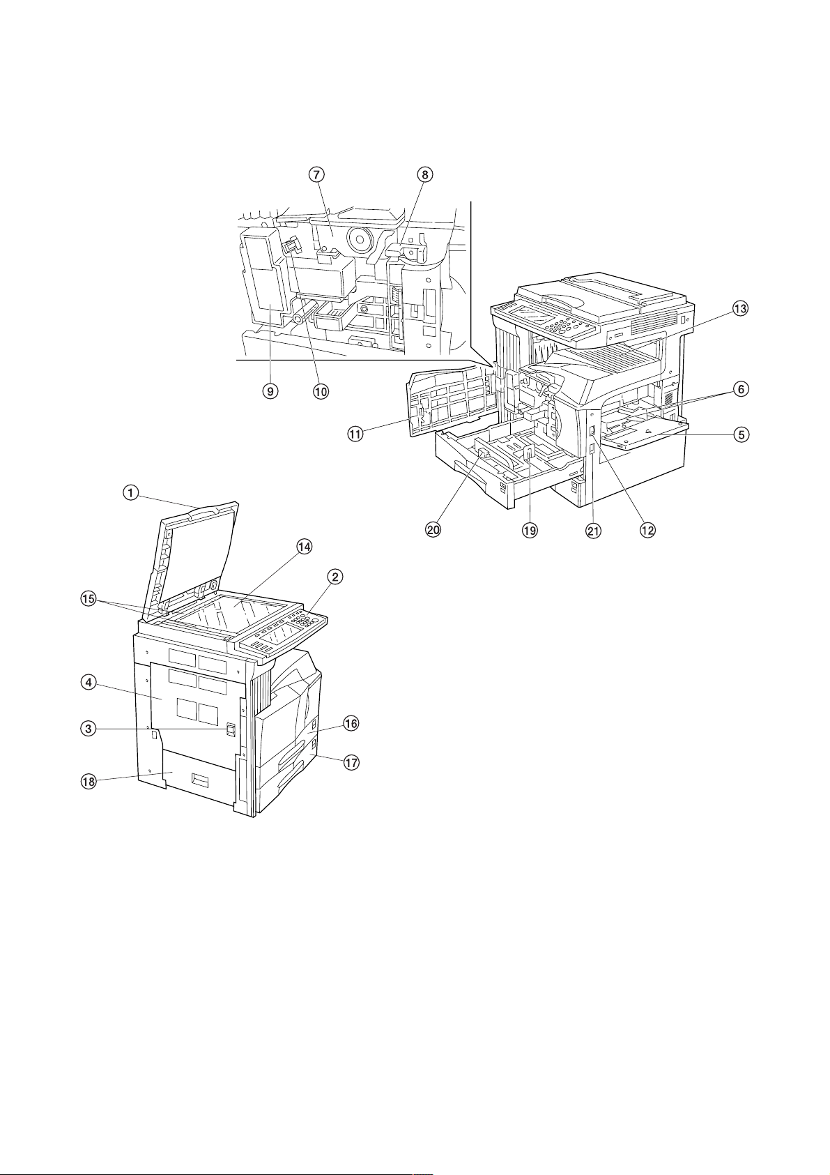
1-1-2 Parts names and their functions
(1) Copier
2BH/J
1 Original cover
2 Operation panel
3 Conveying cover handle
4 Conveying cover
5 Bypass tray
6 Insert guides
7 Toner container
8 Toner container release lever
9 Toner disposal tank
0 Cleaning shaft
! Front cover
Figure 1-1-1
@ Main switch
# Copy store section
$ Platen
% Original size scales
^ Upper drawer
& Lower drawer
* Side cover
( Length adjustment plate
) Width adjustament lever
⁄ Handles for transport
1-1-3
Page 16
2BH/J
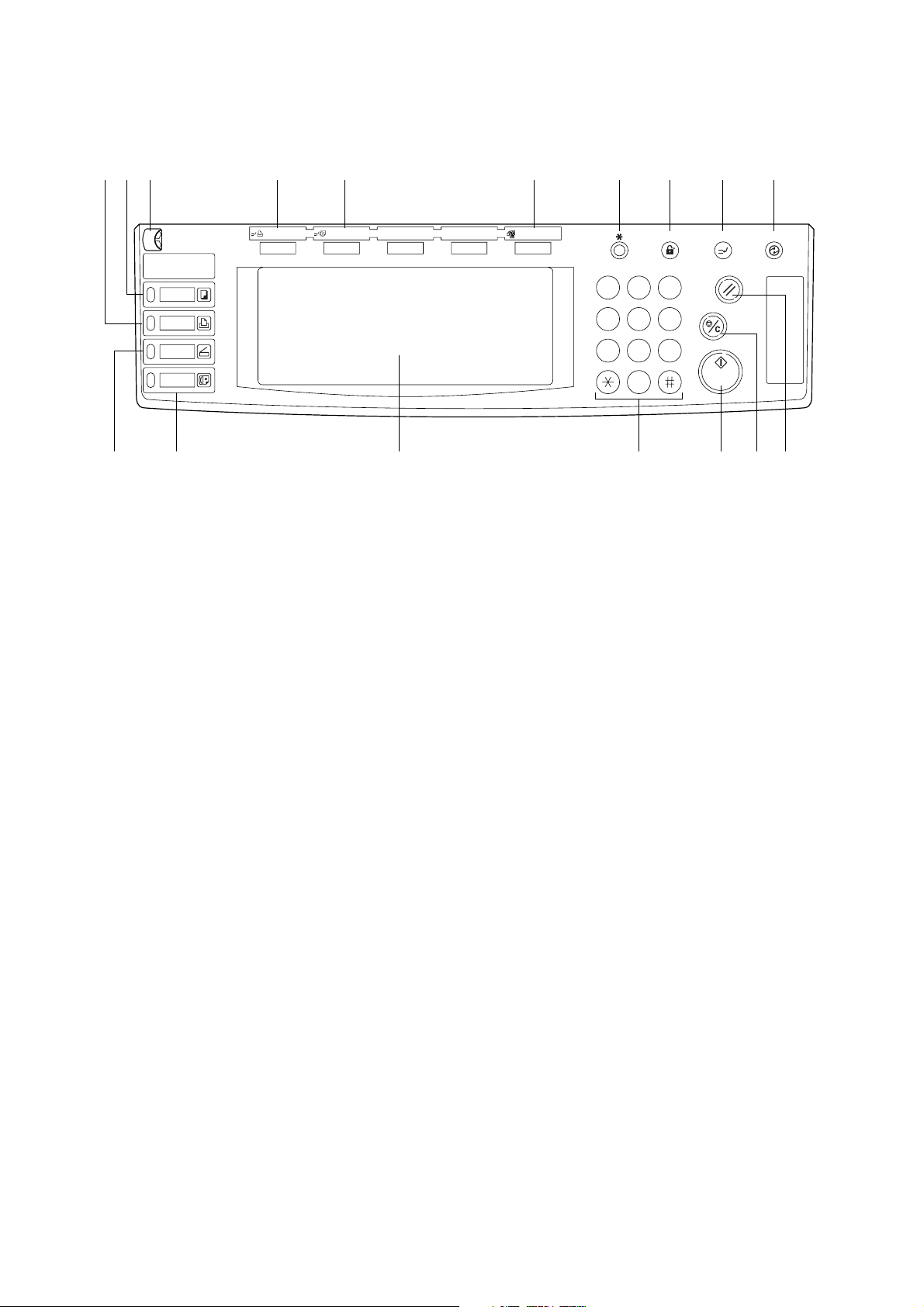
(2) Operation panel
^
Copier
Printer
Scanner
Fax
Printer
Priority Output
Facsimile
Priority Output
& 8 1 2 39
1 Start key (Indicator)
2 Stop/clear key
3 Reset key
4 Energy Saver (preheat) key
5 Interrupt key (Indicator)
6 Management key
7 * (Default) key
8 Numeric key
9 Touch panel
Figure 1-1-2
0!@
Auto Selection
1 2 3
4 5 6
InterruptManagement Energy Saver
Reset
Stop
Clear
7 8 9
0
0 Auto selection key (Indicator)
! Facsimile priority output key (Indicator)
@ Printer priority output key (Indicator)
# Brightness adjustment control dial
$ Copier key (Indicator)
% Printer key (Indicator)
^ Scanner key (Indicator)
& Fax key (Indicator)
Start
4567#$%
1-1-4
Page 17
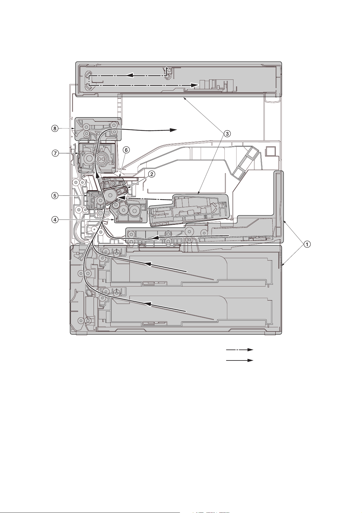
1-1-3 Machine cross section
2BH/J
Figure 1-1-4 Machine cross section
1 Paper feed section
2 Main charging section
3 Optical section
4 Developing section
5 Transfer and separation section
6 Cleaning and charge erasing section section
7 Fixing section
8 Eject and switchback section
Light path
Paper path
1-1-5
Page 18

2BH/J
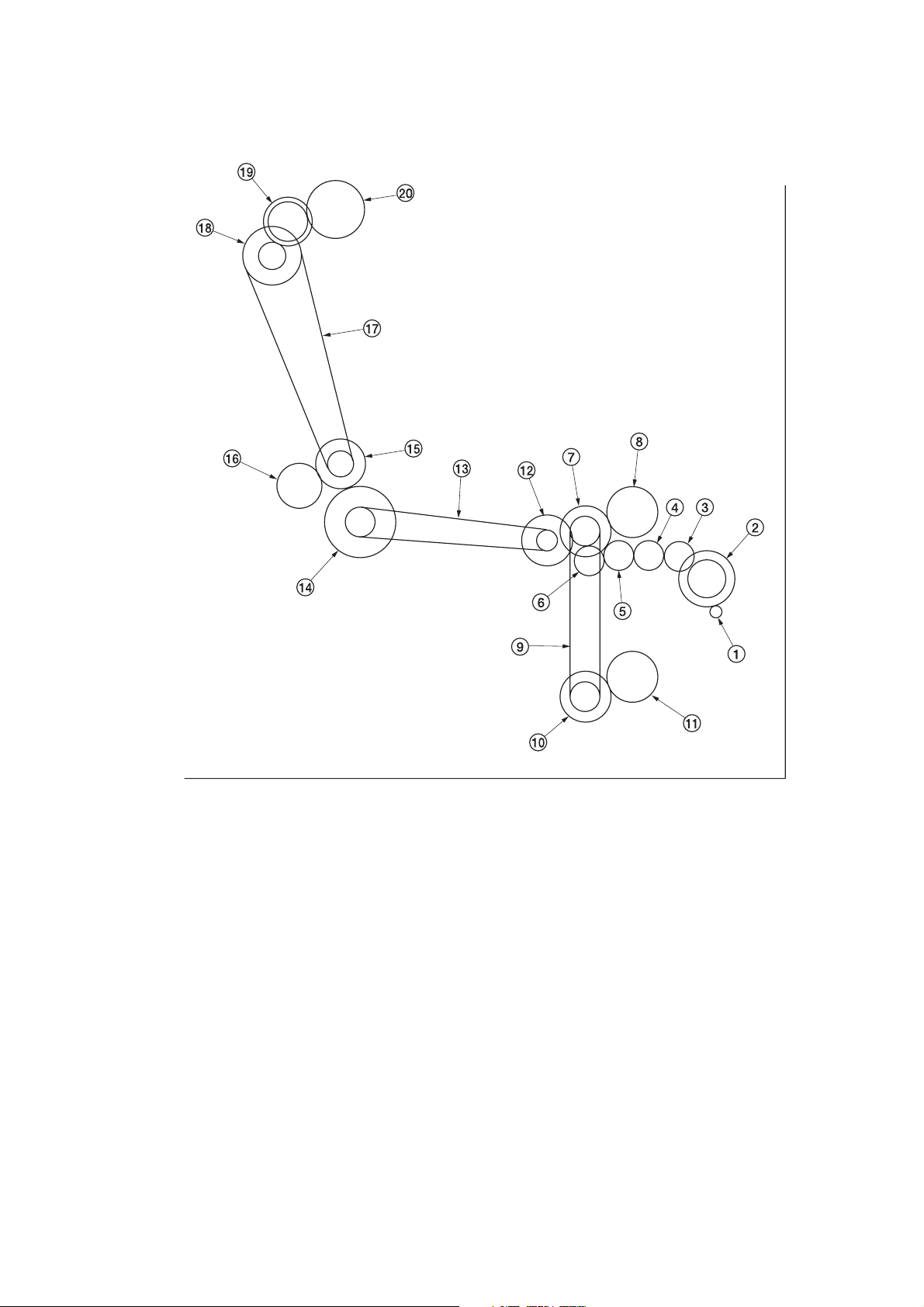
1-1-4 Drive system
(1) Drive system 1 (drive motor and eject motor drive trains)
1-1-6
1 Drive motor gear
2 Drum gear Z76H/Z30H
3 Drum gear Z70H
4 Gear Z76H/Z35H
5 Gear Z50H
6 Gear Z36S/Z31H
7 Gear Z37H/28H
8 Gear Z34H
As viewed from machine rear
Figure 1-1-4
9 Registration clutch gear
0 Gear Z63H/Z45S
! Gear Z37S
@ Gear Z24S
# Joint gear Z32S
$ Eject motor gear
% Gear Z47S/Z28S
^ Eject gear Z30S
Page 19
(2) Drive system 2 (paper feed motor drive train)
2BH/J
1 Paper feed motor gear
2 Gear Z76H/Z35S
3 Feed gear Z25
4 Feed gear Z25
5 Feed gear Z25
6 Feed gear Z25
7 Gear Z41S/Z24S/P30
8 Upper paper feed clutch gear
9 Paper feed drive belt
0 Gear Z41S/Z24S
As viewed from machine rear
Figure 1-1-5
! Lower paper feed clutch gear
@ Gear Z41S/P15
# Bypass drive belt
$ Gear Z60S/P20
% Gear Z41S/P18
^ Gear Z40S/Z32S
& Container drive belt
* Gear Z24S/P40
( Gear Z40S/Z25S
) Container gear
1-1-7
Page 20

2BH/J-1
1-2-1 Drum
Note the following when handling or storing the drum.
• When removing the drum unit, never expose the drum surface to strong direct light.
• Keep the drum at an ambient temperature between 0°C/32°F and 35°C/95°F and at a relative humidity not higher than
85% RH. Avoid abrupt changes in temperature and humidity.
• Avoid exposure to any substance which is harmful to or may affect the quality of the drum.
• Do not touch the drum surface with any object. Should it be touched by hands or stained with oil, clean it.
1-2-2 Toner
Store the toner in a cool, dark place. Avoid direct light and high humidity.
1-2-3 Installation environment
1. Temperature: 10 - 35°C/50 - 95°F
2. Humidity: 15 - 85%RH
3. Power supply: 120 V AC, 11 A
4. Power source frequency: 50 Hz ±0.3%/60 Hz ±0.3%
5. Installation location
• Avoid direct sunlight or bright lighting. Ensure that the photoconductor will not be exposed to direct sunlight or other
strong light when removing paper jams.
• Avoid extremes of temperature and humidity, abrupt ambient temperature changes, and hot or cold air directed onto
the machine.
• Avoid dust and vibration.
• Choose a surface capable of supporting the weight of the machine.
• Place the machine on a level surface (maximum allowance inclination: 1° ).
• Avoid air-borne substances that may adversely affect the machine or degrade the photoconductor, such as
mercury, acidic of alkaline vapors, inorganic gasses, NOx, SOx gases and chlorine-based organic solvents.
• Select a room with good ventilation.
6. Allow sufficient access for proper operation and maintenance of the machine.
Machine front: 1000 mm/39
Machine right: 300 mm/11
220 - 240 V AC, 5.7 A
3
/8" Machine rear: 300 mm/1113/16"
13
/16" Machine left: 300 mm/1113/16"
f
ec
b
3
5
/16"
/8"
5
/8"
a: 745 mm/29
b: 585 mm/23"
c: 646 mm/25
d: 1510 mm/597/16"
a
d
e: 1032 mm/40
f: 961 mm/3713/16"
Figure 1-2-1 Installation dimensions
1-2-1
Page 21
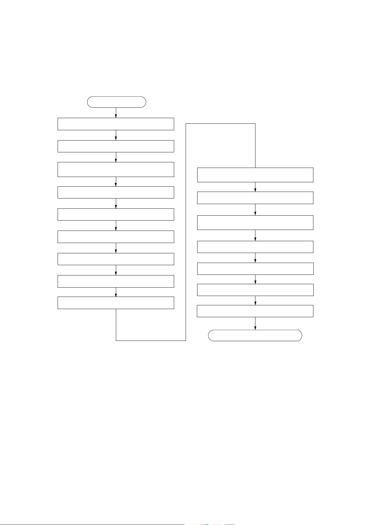
1-3-1 Unpacking and installation
(1) Installation procedure
Start
Unpack.
Remove the tapes and pad.
2BH/J
Install the optional paper feed desk or
large paper deck.
Remove the pins holding light source units 1 and 2.
Install the original cover or the DF.
Install other optional devices.
Install the toner container.
Install the toner disposal tank.
Connect the power cord.
Carry out initial developer setting
(maintenance item U130).
Load paper.
Output an own-status report
(maintenance item U000).
Exit maintenance mode.
Print out the user setting list.
Make test copies.
Attach the function seat.
Completion of the machine installation.
1-3-1
Page 22

2BH/J
Moving the machine
When moving the machine, pull out the four handles for transport on the right and left sides and hold them.
* For the left front handle for transport, open the door and push it into the machine before pulling out the handle.
Handle for
transport
Handle for
transport
Figure 1-3-1
Handle for
transport
Handle for
transport
1-3-2
Page 23
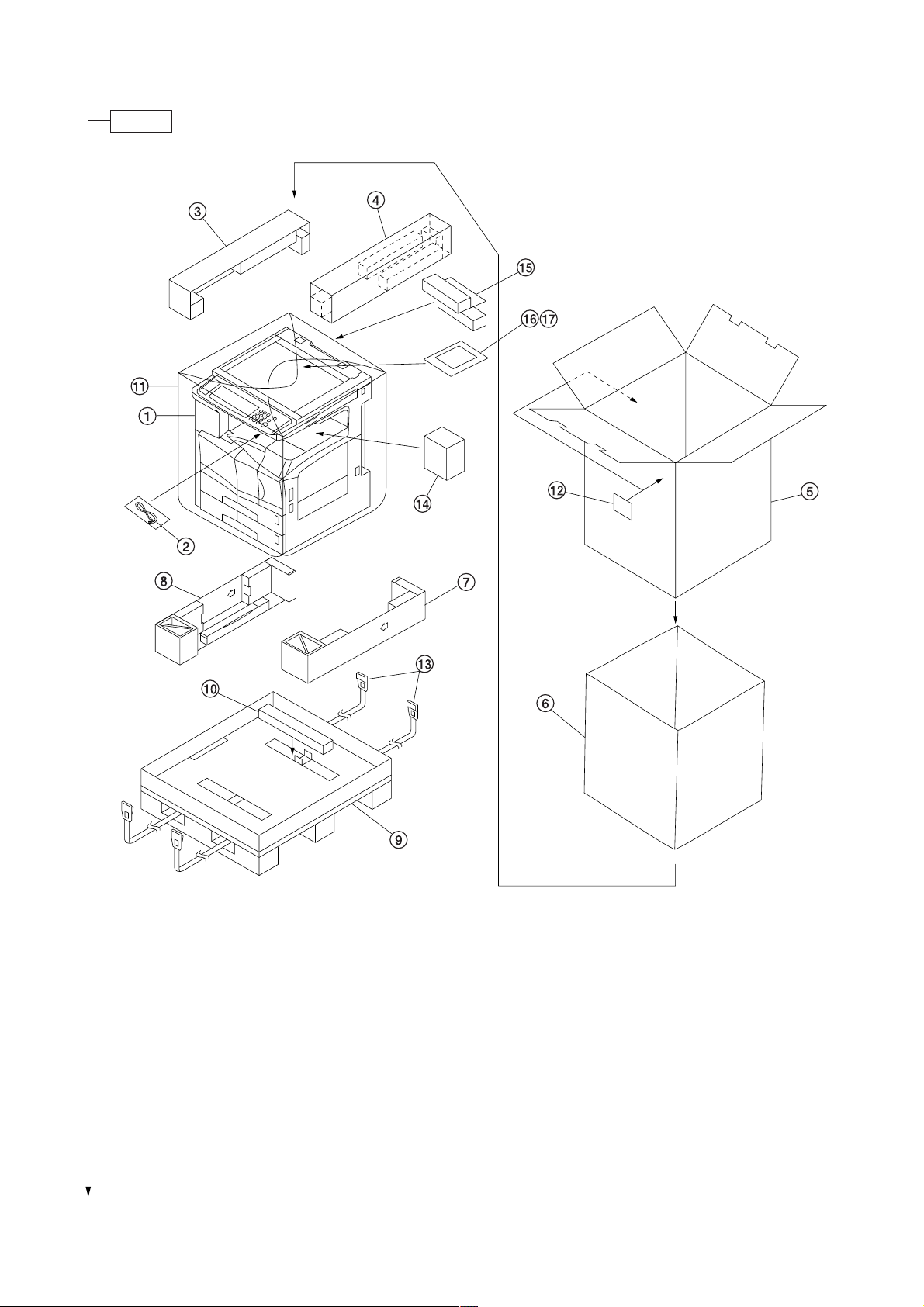
Unpack.
2BH/J
1 Copier
2 Power cord
3 Upper left pad
4 Upper right pad
5 Outer case
6 Inner frame
7 Lower right pad
8 Lower left pad
9 Skid
Figure 1-3-2 Unpacking
0 Bottom pad
! Machine cover
@ Bar code labels
# Belt
$ Eject spacer
% Spacer*
^ Plastic bag
& Operation guide
*220-230 V specifications only.
1-3-3
Page 24
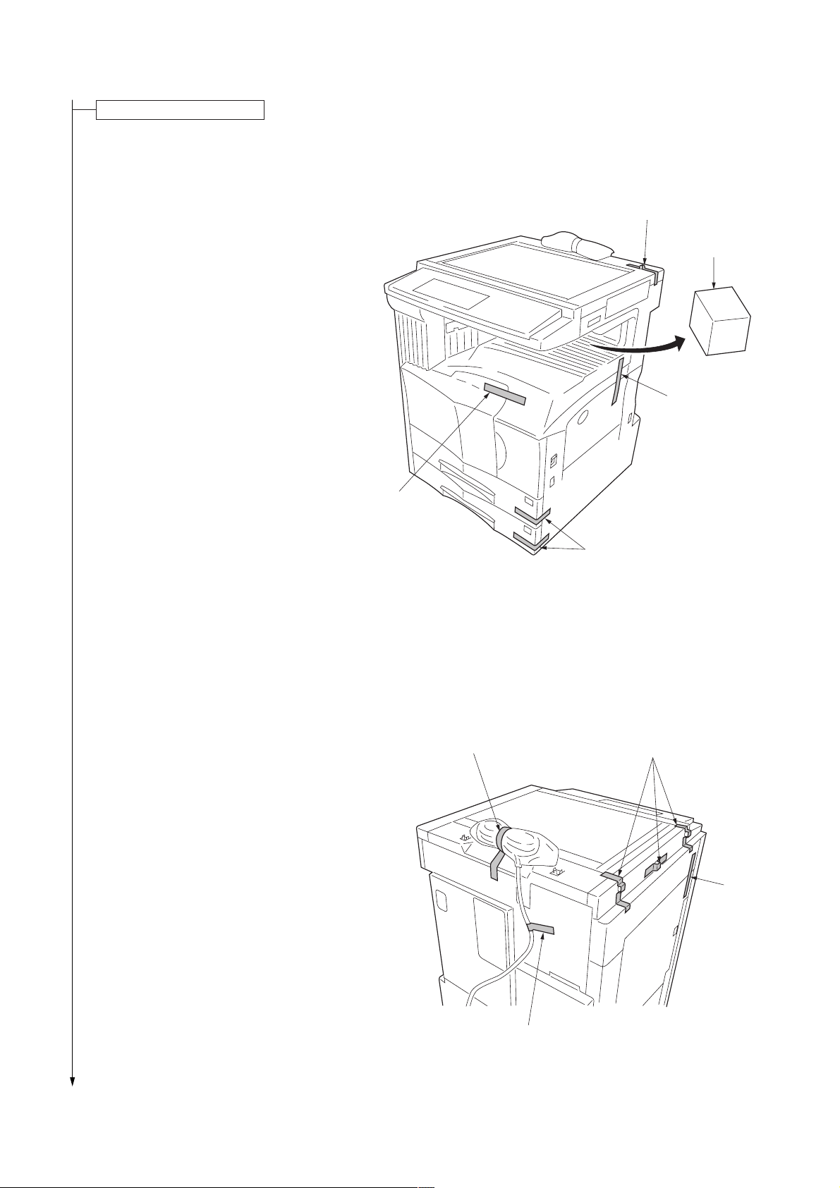
2BH/J
Remove the tapes and pad.
1. Remove the tapes holding the front cover,
bypass tray, drawers and original detection
switch.
2. Remove the pad at the eject section.
Tape
Pad
Tape
3. Remove the three tapes holding the pins for light
source units 1 and 2.
4. Remove the tape holding the conveying cover.
5. Remove the two tapes holding the power cord.*
*120 V specifications only.
Tape
Tape
Tapes
Figure 1-3-3
Tapes
Tape
1-3-4
Tape
Figure 1-3-4
Page 25

6. Pull upper and lower drawers out and remove the
tape holding each of the drawer lift.
Install the optional paper feed desk or large paper deck.
1. Install the optional paper feed desk or large paper
deck as necessary (see page 1-3-18 to 1-3-24).
2BH/J
Tape
Figure 1-3-5
Remove the pins holding light source units 1 and 2.
1. Remove the two pins for light source unit 1 and
the pin for light source unit 2.
Light source unit 1 pins
Light source unit 2 pin
Install the original cover or the DF.
1. Install the original cover or DF (see page 1-3-34 when installing the DF).
Figure 1-3-6
Install other optional devices.
1. Install the optional devices (job separator, duplex unit, finisher, fax board, and/or printer board etc.) as necessary
(see pages 1-3-35 to 1-3-56).
1-3-5
Page 26

2BH/J
Install the toner container.
1. Open the front cover.
2. Turn the toner container release lever to the
direction of arrow.
3. Tap the top of the toner container five to six
times. Then, shake it horizontally eight to ten
times to agitate the toner.
Toner container
release lever
Figure 1-3-7
Toner container
4. Insert the toner container into the copier.
5. Secure the toner container by returning the toner
container release lever.
1-3-6
Figure 1-3-8
Toner container
Toner container
release lever
Figure 1-3-9
Page 27
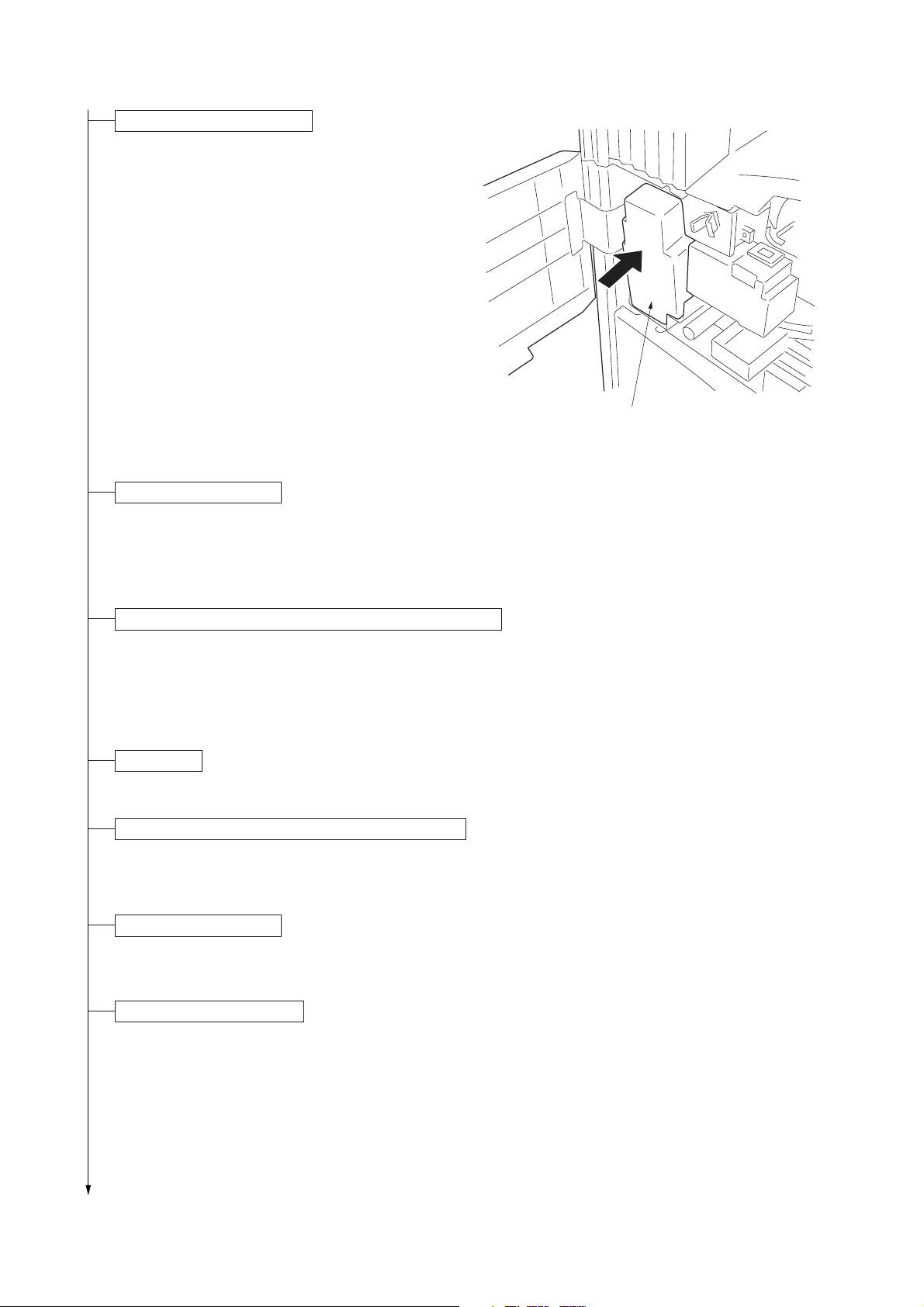
Install the toner disposal tank.
1. Install the toner disposal tank in the copier.
2. Close the front cover.
Connect the power cord.
1. Connect the power cord to the connector on the
copier.*
*200-240 V specifications only.
2. Insert the power plug into the wall outlet.
2BH/J
Toner disposal tank
Figure 1-3-10
Carry out initial developer setting (maintenance item U130).
1. Turn the main switch on and enter the maintenance mode by entering “10871087” using the numeric keys.
2. Enter “130” using the numeric keys and press the start key.
3. Press the start key to execute the maintenance item.
The drive stops within approximately 5 minutes.
4. Press the stop/clear key.
Load paper.
1. Load paper in the drawer.
Output an own-status report (maintenance item U000).
1. Enter “000” using the numeric keys and press the start key.
2. Select “MAINTENANCE” and press the start key to output a list of the current settings of the maintenance items.
3. Press the stop/clear key.
Exit maintenance mode.
1. Enter "001" using the numeric keys and press the start key.
The machine exits the maintenance mode.
Print out the user setting list.
1. Press the * key to enter default setting and press the [Print form] key. The counter report will be output.
1-3-7
Page 28
2BH/J-1
Make test copies.
1. Place an original and make test copies.
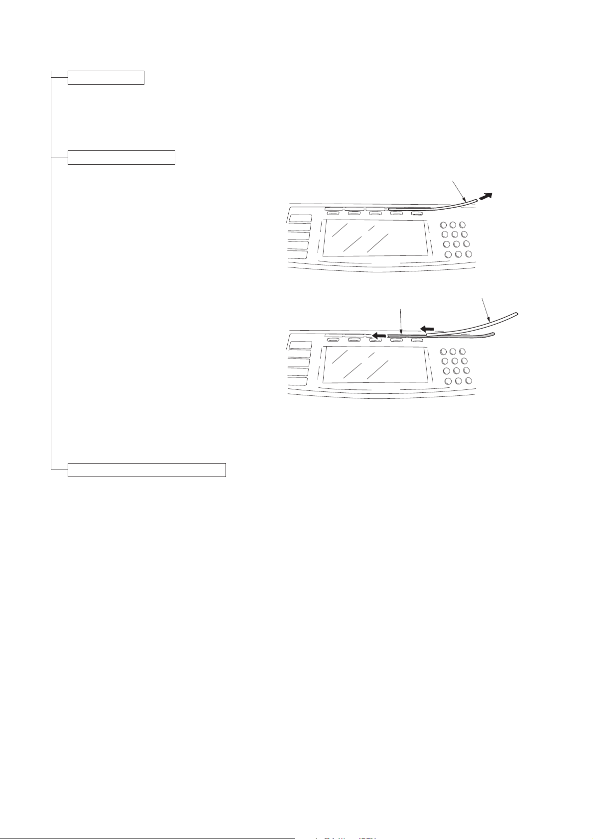
Attach the function seat.
1. Remove the PET film from the operation panel.
2. Fit the relevant function sheet.
If the DF has been installed, select a function
sheet among No. 1 to 4 based on installation of
the fax board and the printer board.
If the DF has not been installed, select a function
sheet among No. 5 to 8 based on installation of
the fax board and the printer board.
3. Refit the PET film to its original position.
PET film
PET film
Function seat
Completion of the machine installation.
Figure 1-3-11
1-3-8
Page 29

1-3-2 Setting initial copy modes
Factory settings are as follows:
2BH/J
Maintenance
item No.
U253
U254
U255
U256
U258
U260
U342
U343
U344
Contents
Switching between double and single counts
Turning auto start function on/off
Setting auto clear time
Turning auto preheat/energy saver
function on/off
Switching copy operation at toner
empty detection
Changing the copy count timing
Setting the ejection restriction
Switching between duplex/simplex copy mode
Setting preheat/energy saver mode
Factory setting
Double count
ON
90s
ON
SINGLE MODE, 0
After ejection
ON
OFF
E2000
1-3-9
Page 30

2BH/J
1-3-3 Copier management
In addition to a maintenance function for service, the copier is equipped with a management function which can be operated
by users (mainly by the copier administrator). In this copier management mode, settings such as default settings can be
changed.
(1) Using the copier management mode
Start
Press the * (Default setting) key.
Press the [Management] key.
Enter the
management code.
Press the [Copy default] key.
Enter the
management code.
Press the [Machine default] key.
Enter the
management code.
Press the [Print form] key.
Execute department management items (page 1-3-11).
Press the [Close] key.
Make copy default settings
(page 1-3-11).
Press the [Close] key.
Make machine default settings
(page 1-3-13).
Press the [Close] key.
Output the setting list
(page 1-3-14).
1-3-10
Press the [Language] key.
Set the language (page 1-3-14).
End
Page 31

2BH/J
(2) Setting department management items
Registering a new department code
Sets a department code and the limit of the
number of copies for that department.
1. Press the [ID-code Reg./Del.] key.
2. Press the [Register] key and press the [#
keys].
3. Enter a department code (8-digit) using the
numeric keys and press the [# keys].
4. Enter the number of copies limit using the
numeric keys. Setting range is 1000 pieces of
units to 1000-999000 pieces. Entering “0”
enables unlimited copying.
5. Press the [Close] key.
6. Press the [Close] key.
7. Press the [On] key.
8. Press the [Close] key.
Deleting a department code
1. Press the [ID-code Reg./Del.] key.
2. Select the department code to be deleted and
press the [Delete] key.
3. Select “Yes” or “No”.
4. Press the [Close] key.
5. Press the [On] key.
6. Press the [Close] key.
Altering the copy limit
1. Press the [# of copy correct] key.
2. Select the department code to be altered and
press the [Correction] key.
3. Enter the number of copies limit using the
numeric keys. Setting range is 1000 pieces of
units to 1000-999000 pieces. Entering “0”
enables unlimited copying.
4. Press the [Close] key.
5. Press the [Close] key.
6. Press the [On] key.
7. Press the [Close] key.
Clearing copy counts
1. Press the [Counter clear] key.
2. Select “Yes” or “No”.
3. Press the [Close] key.
Viewing copy counts
1. Press the [Counter by ID-code] key.
2. View copy counts using the cursor up/down
keys.
3. Press the [Close] key.
4. Press the [Close] key.
Print management list
1. Press the [Print the list] key.
If A4/11" × 81/2" paper is present, the list is
automatically printed out. Otherwise, select
the paper source and press the start key.
(3) Copy default
Exposure mode
Selects the exposure mode at power-on.
1. Select “Exposure mode” and press the
[Change #] key.
2. Select “Manual” or “Auto”.
Exposure steps
Sets the number of exposure steps for the
manual exposure mode.
1. Select “Exposure steps” and press the
[Change #] key.
2. Select “1 step” or “0.5 step”.
Original type
Selects the copy quantity mode at power-on.
1. Select “Original type” and press the [Change
#] key.
2. Select “Text+Photo”, “Photo” or “Text”.
Eco print
Selects the toner economy mode to be
automatically on or off at power-on.
1. Select “ECO print” and press the [Change #]
key.
2. Select “On” or “Off”.
Paper selection
Sets whether the same sized paper as the
original to be copied is automatically selected.
1. Select “Paper selection” and press the
[Change #] key.
2. Select “APS” or “Default cassette”.
Default drawer
Sets the drawer to be selected in cases such as
after the reset key is pressed.
1. Selct “Default cassette” and press the
[Change #] key.
2. Select priority drawer.
Default magnification
Selects whether auto magnification selection or
100% magnification is to be given priority when
the sizes of the original and copy paper are
different.
1. Select “Default magnification” and press the
[Change #] key.
2. Select “Manual” or “AMS”.
Auto exposure adjustment
Adjusts the exposure for the auto exposure
mode.
1. Select “Auto exposure adjustment” and press
the [Change #] key.
2. Press the [Lighter] or [Darker] key to adjust
default setting of copy exposure.
Setting range: -3 to +3
1-3-11
Page 32

2BH/J
Manual exposure adjustment (Mixed)
Adjusts the exposure to be used when text and
photo original is selected for the image mode.
1. Select “Manual exp. adj. (Mixed)” and press
the [Change #] key.
2. Press the [Lighter] or [Darker] key to adjust
default setting of copy exposure.
Setting range: -3 to +3
Manual exposure adjustment (Text)
Adjusts the exposure to be used when text
original is selected for the image mode.
1. Select “Manual exp. adj. (Text)” and press the
[Change #] key.
2. Press the [Lighter] or [Darker] key to adjust
default setting of copy exposure.
Setting range: -3 to +3
Manual exposure adjustment (Photo)
Adjusts the exposure to be used when photo
original is selected for the image mode.
1. Select “Manual exp. adj. (Photo)” and press the
[Change #] key.
2. Press the [Lighter] or [Darker] key to adjust
default setting of copy exposure.
Setting range: -3 to +3
Display register key
Sets whether or not to display the Register key in
the copy operation screen.
1. Select “Display register key” and press the
[Change #] key.
2. Select “On” or “Off”.
Customize the base screen (main function)
Changes the layout of the main functions of the
base screen.
1. Select “Customize (Main function)” and press
the [Change #] key.
2. Change the layout to press [Move ahead] or
[Move to behind].
Customize the copy operating screen (add function)
Changes the layout of the functions except the
main functions of the copy operating screens.
1. Select “Customize (Add function)” and press
the [Change #] key.
2. Change the layout to press [ ← ].
Margin width
Sets the default setting of the margin width for the
margin copying.
1. Select “Default margin width” and press the
[Change #] key.
2. Press the +/- keys to adjust default margin
width.
Setting range: 0 to 3/4" (inch specifications)
0 to 18 mm (metric specifications)
Border erase width
Sets the default setting of the border erase width
for the border erase mode.
1. Select “Default erase width” and press the
[Change #] key.
2. Press the +/- keys to adjust default erase
width.
Setting range: 0 to 3/4" (inch specifications)
0 to 18 mm (metric specifications)
Copy limit
Sets the number of copies limit for multiple
copying.
1. Select “Preset limit” and press the [Change #]
key.
2. Press the +/- keys to set copy preset in one
job.
Setting range: 1 to 999 copies
1-3-12
Page 33

2BH/J
(4) Machine default
Auto drawer switching
Sets whether the auto drawer switching function
is available.
1. Select “Auto cassette switching” and press
the [Change #] key.
2. Select “On” or “Off”.
Special paper
Sets the drawer for such special paper as colored
paper or recycled paper.
1. Select “Special paper” and press the [Change
#] key.
2. Select “1st paper” or “2nd paper”.
APS for special paper
Sets whether to use the paper source with the
special paper for auto paper selection and auto
drawer switching.
1. Selct “APS for special paper” and press the
[Change #] key.
2. Select “On” or “Off”.
Paper size (upper drawer)
Sets the paper size for upper drawer.
1. Select “Paper size (1st cassette)” and press
the [Change #] key.
2. Select the paper size.
Paper size (lower drawer)
Sets the paper size for lower drawer.
1. Select “Paper size (2nd cassette)” and press
the [Change #] key.
2. Select the paper size.
Paper type (upper drawer)
Sets the paper type (standard or special) for
upper drawer.
1. Select “Paper type (1st cassette)” and press
the [Change #] key.
2. Select the paper type.
Paper type (lower drawer)
Sets the paper type (standard or special) for
lower drawer.
1. Select “Paper type (2nd cassette)” and press
the [Change #] key.
2. Select the paper type.
Check bypass sizing
Sets whether or not to display the paper size key
of the basic screen when copying with the bypass
tray.
1.Select “Check bypass express” and press the
[Change #] key.
2. Selct “On” or “Off”.
Auto shutoff time
Sets the auto shutoff time.
1. Select “Auto shut-off time” and press the
[Change #] key.
2. Press the +/- keys to set the auto shutoff
time.
Setting range: 15 to 240 minutes
Auto preheat time
Sets the auto preheat time.
1. Select “Auto preheat time” and press the
[Change #] key.
2. Press the +/- keys to set the auto preheat
time.
Setting range: 1 to 45 minutes
Note: Set the auto preheat time to be shorter
than the auto shutoff time.
Copy eject location setting
Selects whether to eject copies to copier, finisher
or job separator.
1. Select “Select Copy output mode” and press
the [Change #] key.
2. Select the eject location.
Key sound
Sets if a beep sounds when a key on the key
press panel is pressed.
1. Select “Key sound ON/OFF” and press the
[Change #] key.
2. Select “On” or “Off”.
Silent mode
Selects whether or not to enter silent mode after
copying.
1. Select “Silent Mode” and press the [Change
#] key.
2. Select “On” or “Off”.
Management code change
Changes the management code.
1. Select “Management code change” and press
the [Change #] key.
2. Enter the 4-digit management code using the
numeric keys and press the enter key.
Auto shutoff
Sets whether the auto shutoff function is
available.
1. Select “Auto shut-off” and press the [Change
#] key.
2. Select “On” or “Off”.
1-3-13
Page 34

2BH/J
(5) Report
Outputs the setting reports.
1. Press the [Print form] key.
2. Select the report.
Copy report/Option report/Counter report/
Machine report
(6) Language
Switches the language to be displayed on the
press panel.
1. Press the [Language] key.
2. Select the display language.
1-3-14
Page 35

1-3-4 Installing the key counter (option)
Key counter installation requires the following parts:
Key counter set (P/N 2A369703)
Contents of the set:
• Key counter cover (P/N 2A360010)
• Key counter retainer (P/N 66060030)
• Key counter cover retainer (P/N 66060022)
• Key counter mount (P/N 66060040)
• Key counter socket assembly (P/N 41529210)
• Four (4) M4 × 6 bronze TP-A screws (P/N B4304060)
• Two (2) M4 × 10 bronze TP-A screws (P/N B4304100)
• One (1) M4 × 20 bronze TP-A screw (P/N B4304200)
• One (1) M4 × 6 chrome TP-A screw (P/N B4104060)
• One (1) M3 × 8 bronze binding screw (P/N B1303080)
• One (1) M4 × 30 bronze binding screw (P/N B1304300)
• Two (2) M3 × 6 bronze flat-head screws (P/N B2303060)
• One (1) M3 bronze nut (P/N C2303000)
2BH/J
Procedure
1. Fit the key counter socket assembly to the
key counter retainer using the two screws
and nut.
2. Fit the key counter mount to the key counter
cover using the two screws, and attach the
key counter retainer to the mount using the
two screws.
3. Remove the three screws holding the middle
right cover and then the cover.
4. Cut out the aperture plate on the middle right
cover using nippers.
5. Pass the connect inside the copier through
the aperture and refit the middle right cover.
M4 × 6 screws (B4304060)
Key counter retainer (66060030)
M3 nut
(C2303000)
M4 × 6 screws (B4304060)
Key counter socket assembly
(41529210)
M3 × 6 flat-head screws (B2303060)
Figure 1-3-12
Middle right cover
Key counter mount (66060040)
Key counter cover
(2A360010)
Aperture
Figure 1-3-13
Connector
1-3-15
Page 36

2BH/J
6. Pass the connector of the key counter
through the aperture in the key counter
retainer, and insert into the connector of the
copier.
7. Seat the projection of the key counter cover
retainer in the aperture in the middle right
cover.
8. Fit the key counter cover with the key counter
socket assembly inserted to the key counter
cover retainer on the copier using the screw.
9. Insert the key counter into the key counter
socket assembly.
Key counter cover retainer (66060022)
Key conuter cover
Connector
10. Turn the main switch on and enter the
maintenance mode.
11. Run maintenance item U204 and select
“KEY-COUNTER.”
12. Exit the maintenance mode.
13. Check that the message requesting the key
counter to be inserted is displayed on the
touch panel when the key counter is pulled
out.
14. Check that the counter counts up as copies
are made.
Connector
Projection
M4 × 30 screws
(B1304300)
Figure 1-3-14
1-3-16
Page 37

1-3-5 Installing the drawer heater (option)
Drawer heater installation requires the following parts:
• Drawer heater (P/N 34860030): for 120 V specifications
• Drawer heater (P/N 33960020): for 220 - 240 V specifications
• Band (P/N M2107120)
Procedure
1. Pull the upper and lower drawers out.
2. Fit the drawer heater to the bottom of the
machine and bind the wire of the drawer
heater with the band.
3. Put the wire of the drawer heater out of the
machine through the aperture of the rear
frame.
2BH/J
Aperture
Drawer heater
Band
Figure 1-3-15
4. Remove the four screws and the two
connectors and then remove the power
source unit from the rear side of the machine.
5. Remove the two screws and pull out the wire
of the drawer heater that has been put out of
the rear frame while raising the power source
PCB unit.
6. Insert the connector of the drawer heater into
the connector of the machine.
7. Refit all the removed parts.
Connectors
Power source unit
Figure 1-3-16
Wire of the drawer heater
Figure 1-3-17
Power source PCB unit
Connector
1-3-17
Page 38

2BH/J
1-3-6 Installing the paper feed desk (option)
Preparation
1. Remove the lower drawer from the copier.
2. Place the copier on top of the paper feed
desk with the positioning pins at the front left
and right of the paper feed desk aligned with
the holes in the base of the copier.
Lower drawer
Figure 1-3-18
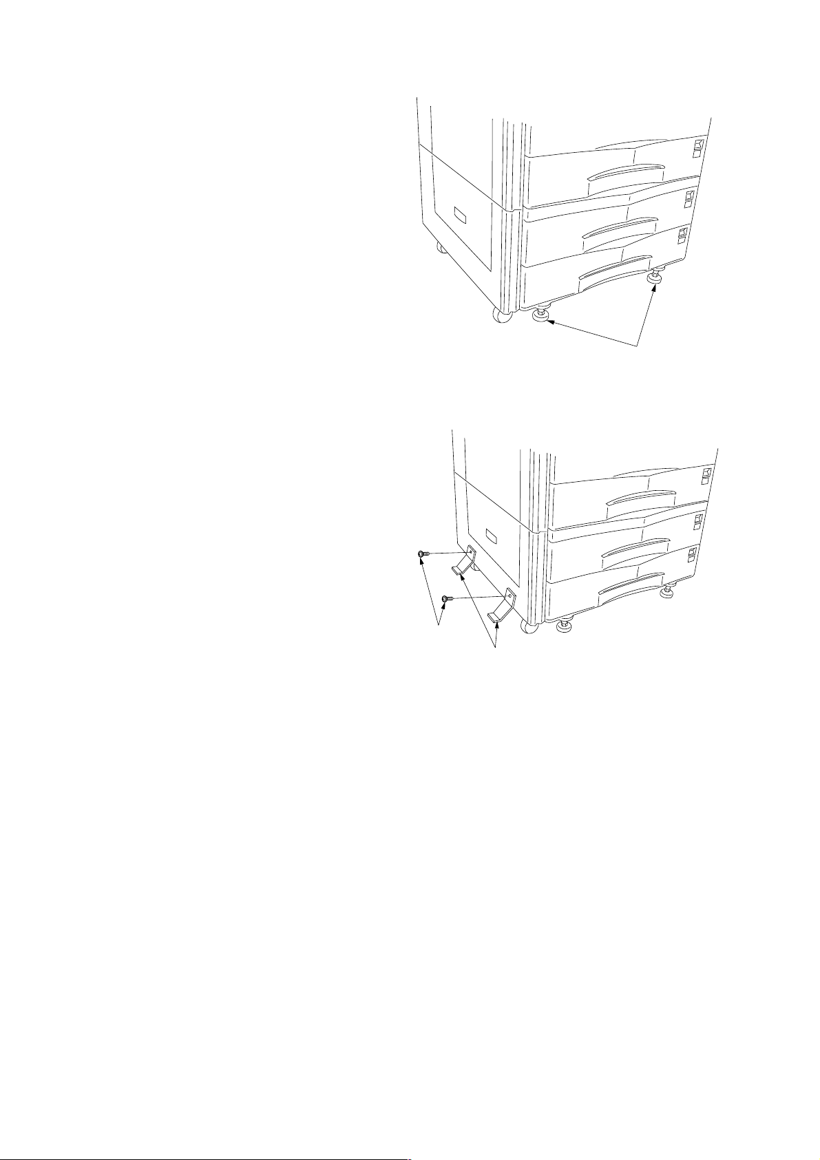
3. Secure the copier to the paper feed desk
using the two pins.
4. Refit the lower drawer to the copier.
Pin
Holes
Pins
Paper feed desk
Figure 1-3-19
Pin
1-3-18
Paper feed desk
Figure 1-3-20
Page 39

5. Remove the screw and then the cover from
the rear of the paper feed desk.
6. Remove the screw from the copier.
7. Insert the 12-P connector of the paper
feed desk into the connector on the copier.
Screw
Screw
Figure 1-3-21
2BH/J
Cover
8. Route the harness through the clamp on the
retainer.
9. Fit the retainer using the screw removed in
step 6 and the two CVM4 × 06 cross-head
chromate binding screws.
10. Refit the cover.
12-P connector
Figure 1-3-22
Clamp
Harness
Retainer
Screw
CVM4 × 06 cross-head
chromate binding screws
Figure 1-3-23
1-3-19
Page 40
2BH/J
11. Turn the four leveling bolts until they reach
the floor and adjust them to level the
machine.
12. Fit the two stays to the left of the paper feed
desk (one toward the front and the other the
rear) using the two M4 × 10 chrome TP
screws such that they make contact with the
floor.
Note: Do not fit the stays if the finisher is to
be installed.
13. Connect the copier power plug to the wall
outlet and turn the copier main switch on.
14. Load paper into the drawer and make a test
copy to check the operation.
Leveling bolts
Figure 1-3-24
M4 × 10 chrome
TP screws
Stays
Figure 1-3-25
1-3-20
Page 41

1-3-7 Installing the large paper deck (option)
Preparation
1. Remove the lower drawer from the copier.
2. Place the copier on top of the large paper
deck with the positioning pins at the front left
and right of the large paper deck aligned with
the holes in the base of the copier.
2BH/J
Lower drawer
Figure 1-3-26
3. Secure the copier to the large paper deck
using the two pins.
4. Refit the lower drawer to the copier.
Hole
Pin
Large paper desk
Pin
Hole
Pin
Figure 1-3-27
Pin
Figure 1-3-28
Large paper desk
1-3-21
Page 42

2BH/J
5. Remove the screw and then the cover from
the rear of the large paper deck.
6. Remove the screw from the rear of the copier.
7. Insert the 12-pin connector of the large paper
deck into the connector on the copier.
Screw
Screw
Figure 1-3-29
Cover
8. Fit the retainer using the screw removed in
step 6 and the two CVM4 × 06 cross-head
chromate binding screws.
9. Refit the cover using the screw (see step 5).
12-pin connector
Figure 1-3-30
Retainer
CVM4 × 06 cross-head
chromate binding screw
CVM4 × 06 cross-head
chromate binding screw
Screw
1-3-22
Figure 1-3-31
Page 43

10. Turn the four leveling bolts until they reach
the floor and adjust them to level the
machine.
2BH/J
Leveling bolts
Figure 1-3-32
11. Fit the stay to the lower left of the large paper
deck toward the rear using the two M4 × 16
chrome TP screws such that it makes contact
with the floor.
Note: Do not fit the stay if the finisher is to be
installed.
Setting the paper size
1. Open the large paper deck.
2. Move the sliders at the machine front and
rear inward (two at each point).
3. Remove the screw from each of the front and
rear lateral size adjusters.
Stay
M4 × 16 chrome
TP screws
Figure 1-3-33
Screw
Leteral size adjuster
Sliders
Leteral size adjuster
Sliders
Screw
Figure 1-3-34
1-3-23
Page 44
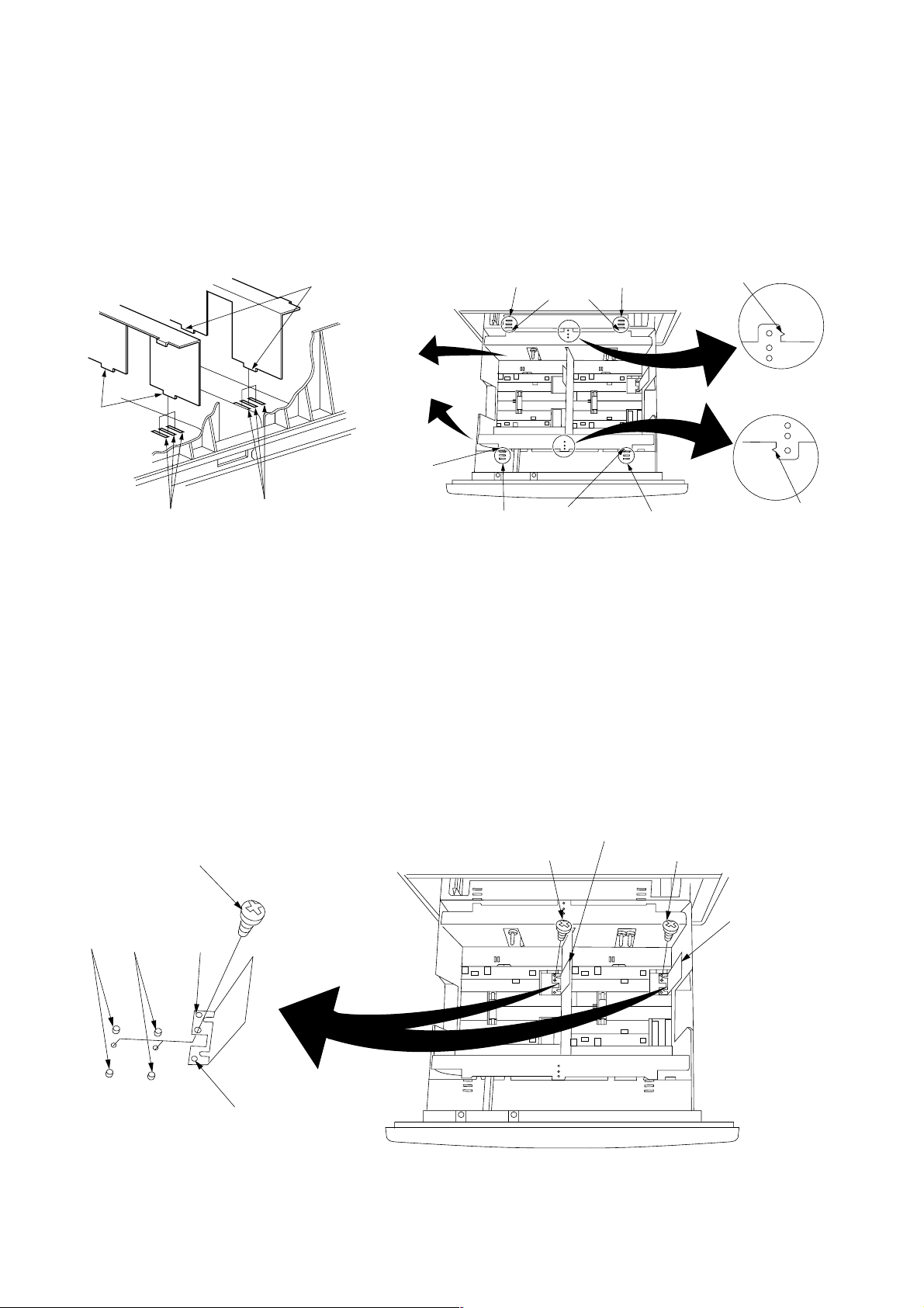
2BH/J
4. Insert the upper tabs and lower tabs of the
front and rear lateral size adjusters into the
upper slots and lower slots respectively such
that the size indicators point to the size of
paper to be used. Secure the lateral size
adjusters using the screw for each.
5. Move the front and rear sliders (two at each
point) outward until they make contact with
the lateral size adjusters.
Lower tabs
Lower tabs
Lower slots
Lower slots
Upper tab
Upper slots
Upper slots
Upper tabs
Upper tab
Upper slots
Upper slots
Size indicator
A4
LT
B5
B5
LT
A4
Size indicator
Steps 6 to 9 are for metric specifications only.
6. Remove the screw from each of the left and
right longitudinal size adjusters.
7. Align the pin holes in the left and right
longitudinal size adjusters with the A4 pins or
B5 pins according to the size of paper to be
used. Secure the adjusters using the screw
for each.
8. Connect the copier power plug to the wall
outlet and turn the copier main switch on.
9. Run maintenance item 208 and set the paper
size for the large paper deck (B5/A4).
10. Load paper into the drawer and make a test
copy to check the operation.
Screw
B5 pins
A4 pins
Pin hole
Figure 1-3-35
Longitudinal size adjuster
Screw
Screw
Longitudinal size adjuster
B5
1-3-24
A4
Pin hole
Figure 1-3-36
Page 45
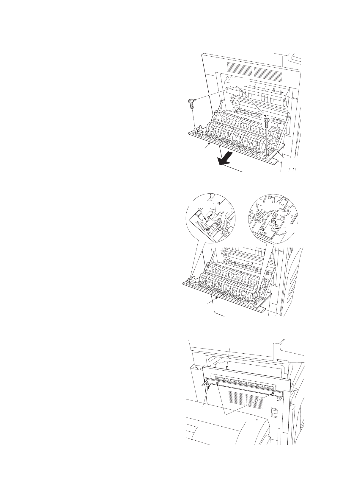
1-3-8 Installing the saddle finisher/switchback unit (option)
Preparation
1. Open the conveying cover of the copier.
2. Remove the two screws securing the
feedshift guide assembly and then the
assembly.
Feedshift guide
assembly
Screws
Figure 1-3-37
Conveying
cover
2BH/J
3. Fit the curl eliminator to the conveying cover
such that the projections on the cover fit into
the two ends of the curl eliminator.
4. Secure the curl eliminator using the two
screws removed in step 2.
5. Close the conveying cover.
6. Fit the latch catch to the conveying cover
using two M4 × 10 binding screws.
Projection
Curl eliminator
Screw
Figure 1-3-38
Conveying cover
Screw
Projection
Latch catch
M4 × 10 binding screws
Figure 1-3-39
1-3-25
Page 46

2BH/J
CN15
J1
Board
supports
Main PCB
Board support
IPC PCB
IPC PCB
7. Remove the two screws securing the shield
cover and then the cover.
8. Detach the 10-pin connector (four wires) from
CN4 on the main PCB and connect it to J2 on
the IPC PCB.
Screws
Shield cover
Figure 1-3-40
10-pin connector
IPC PCB
J2
9. Connect J1 on the IPC PCB to CN15 on the
main PCB.
10. Insert the three board supports of the IPC
PCB into the main PCB to secure them.
11. Refit the shield cover.
Main PCB
CN15
CN4
10-pin connector
Figure 1-3-41
1-3-26
Figure 1-3-42
Page 47

2BH/J
12. Align the rail retainer with the groove of the
guide rail and attach the rail retainer to the
guide rail. Make sure that the plate spring of
the rail retainer fits into the groove and the
edge of the guide rail fits between the pulleys
on the reverse side of the rail retainer.
When the switchback unit is not to be installed
13. Orient the guide rail such that its pulley is
positioned toward the copier, and then fit a
caster rail to each side of the rail retainer.
When the switchback unit is to be installed
14. Attach a spacer to each end of the rail
retainer using two M4 × 6 binding screws for
each.
15. Orient the guide rail such that its pulley is
positioned toward the copier, and then fit the
caster rails to the spacer.
Guide rail
Figure 1-3-43
Rail retainer
Plate spring
Caster rail
Rail retainer
Guide rail
16. Secure the rail retainer to the copier using
two M4 × 10 binding screws such that the
front and rear gaps between the floor and rail
retainer are approximately 10 mm.
Rail retainer
Caster rail
M4 × 6
binding screws
Spacer
Rail retainer
Rail retainer
Caster rail
Spacer
Pulley
Caster railGuide rail
Figure 1-3-44
Rail retainer
10 mm 10 mm
M4 × 6
binding screws
M4 × 10
binding screws
Figure 1-3-45
1-3-27
Page 48
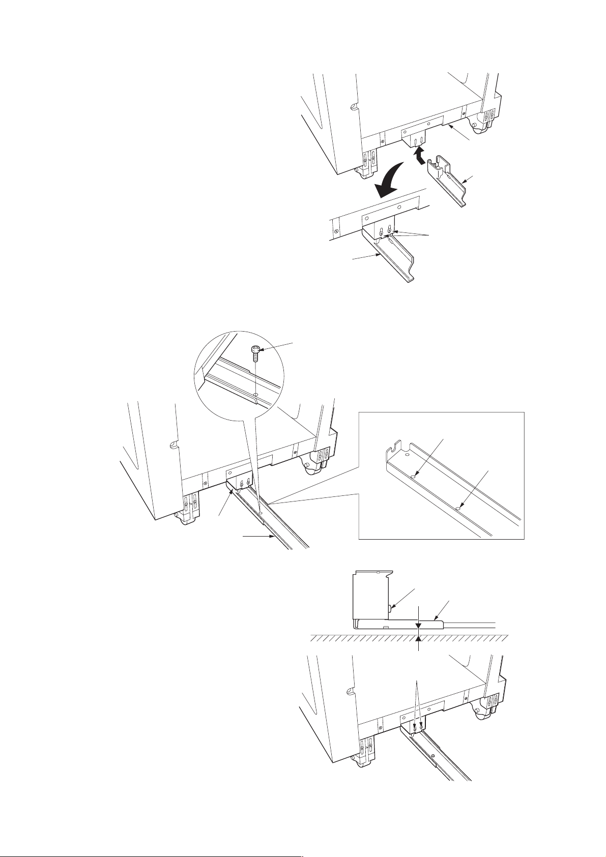
2BH/J
17. Slightly lift the bottom of the finisher and
insert the rail fixing plate into the finisher, and
then join them by inserting two M4 × 6
binding screws loosely.
18. Insert the guide rail into the rail fixing plate
and secure it using an M4 × 6 binding screw
at the position where the screw hole in it and
that in the rail fixing plate meet.
Note: When installing the switchback unit,
use screw hole a in the guide rail; when not
installing the switchback unit, use screw
hole b in the guide rail.
Finisher
Rail fixing plate
M4 × 6
binding screws
Rail fixing plate
Figure 1-3-46
M4 × 6
binding screw
Rail fixing plate
Guide rail
19. Adjust the position of the rail fixing plate so
that the gap between the plate and the floor is
approximately 8.0 mm, and then tighten the
two loosely fitted M4 × 6 binding screws.
Screw hole a
Screw hole b
Figure 1-3-47
M4 × 6
binding screws
Rail fixing plate
8.0 mm
M4 × 6
binding screws
1-3-28
Figure 1-3-48
Page 49

20. Fit the eject tray to the finisher by hooking the
two claws and secure it using two M4 × 6
binding screws.
21. Open the front panel and insert the stapler
unit into the finisher.
22. Close the front panel.
Claw
Eject tray
M4 × 6
binding screws
2BH/J
Claw
Figure 1-3-49
Installing the switchback unit
1. Remove the two support rubbers on the right
of the finisher and loosely fit the two M3 × 8
binding screws in their places.
2. Remove the two screws.
Stapler unit
Front panel
Figure 1-3-50
Finisher
Screw
Support rubber
Screw
Support rubber
M3 × 8
binding screws
Figure 1-3-51
1-3-29
Page 50
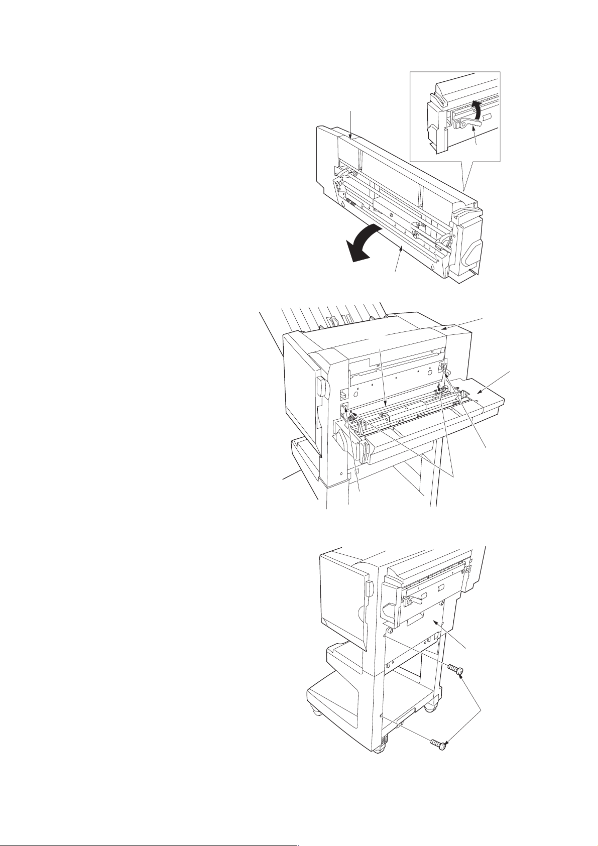
2BH/J
3. Release the hook of the switchback unit by
lifting the release lever.
4. Fit the switchback unit to the finisher by
hanging the hook of the switchback unit on
the loosely fitted M3 × 8 binding screws.
5. Tighten the loosely fitted M3 × 8 binding
screws.
6. Secure the switchback unit using two M4 × 12
TP screws.
7. Close the switchback unit.
Switchback unit
Release lever
Hook
Figure 1-3-52
Finisher
Hook
Switchback unit
8. Remove the two screws from the cover of the
finisher.
M4 × 12
TP screw
Figure 1-3-53
M4 × 12
TP screw
M3 × 8
binding screws
Finisher
Screws
1-3-30
Figure 1-3-54
Page 51

9. Insert the rib of the front cover into the groove
in the top cover of the switchback unit, and
then fit the front cover to the finisher.
10. Secure the front cover by fitting an M4 × 12
TP screw and M4 × 16 TP screw into the
holes where screws were inserted
(see step 8).
Rib
Groove
Front cover
2BH/J
Finisher
M4 × 12
TP screw
M4 × 16
TP screw
Figure 1-3-55
11. Fit the two support rubbers removed in step 1
to the switchback unit.
12. If the finisher and the copier do not engage
securely, perform the following finisher height
adjustment.
Adjusting the height of the finisher
1. Remove the two covers from the lower left
part of the finisher by removing one screw
each.
2. Remove the four caps from above the four
casters of the finisher.
Support rubbers
Figure 1-3-56
Cap
Cover
Screws
Cap
Caster
Cover
Figure 1-3-57
1-3-31
Page 52

2BH/J
3. Loosen the two screws on each of the four
casters.
4. Adjust the height of the rear right caster by
turning its adjustment bolt using a crossheaded screwdriver so that the axis of the pin
of the latch catch is aligned with the middle of
the three markings on the right of the slot of
the finisher or switchback unit when the
finisher is joined to the copier (viewed from
the machine front).
Note: Turning the adjustment bolts clockwise
lowers the finisher, while turning them
counterclockwise lifts the finisher.
Pin
Adjustment bolt
Slot
Screws
5. Adjust the height of the front right caster in
the same manner as in step 4 so that the axis
of the pin of the latch catch is aligned with the
marking above the slot and the center of the
two hooks on the finisher align with the center
of the holes on the latch catch when the
finisher is joined to the copier (viewed from
above).
Slot
Pin
Caster
Figure 1-3-58
Pin
HolesHooks
1-3-32
Pin
Figure 1-3-59
Page 53

6. Adjust the height of the left two casters in the
same manner as in step 4 so that the top and
bottom gaps (A) between the finisher and the
copier are the same when the finisher is
detached from the copier.
7. Retighten the two screws on each of the four
casters.
8. Refit the two covers and four caps.
2BH/J
A
A
Figure 1-3-60
Connecting the signal cable
1. Connect the signal cable of the finisher to the
copier. If the switchback unit has been
installed, connect the signal cable of the
switchback unit, as well.
2. Insert the copier power plug to the wall outlet
and turn the main switch on.
3. Make test copeies and check that the finisher
and the switchback unit operate correctly.
Signal cable of
the finisher
Signal cable of
the switchback unit
Figure 1-3-61
1-3-33
Page 54

2BH/J
1-3-9 Installing the sheet-through document holder (option)
Preparation
1. Insert the DF into the copier.
2. Connect the connector of the DF to the
copier.
3. Insert the copier power plug to the wall outlet
and turn the main switch on.
DF
Figure 1-3-62
DF
4. Run maintenance item U211 to set “SADF”
(25 cpm copier only).
5. Place the original on the DF and make a test
copy. Check the operation and the copy
image.
6. If the copy image is different from the original,
run the following adjustment.
Maintenance item U70 (sub-scan line
•
adjustment)(see page 1-4-15)
Maintenance item U71 (leading edge timing
•
adjustment)(see page 1-4-16)
Maintenance item U72 (center line
•
adjustment)(see page 1-4-17)
Connector
Figure 1-3-63
1-3-34
Page 55
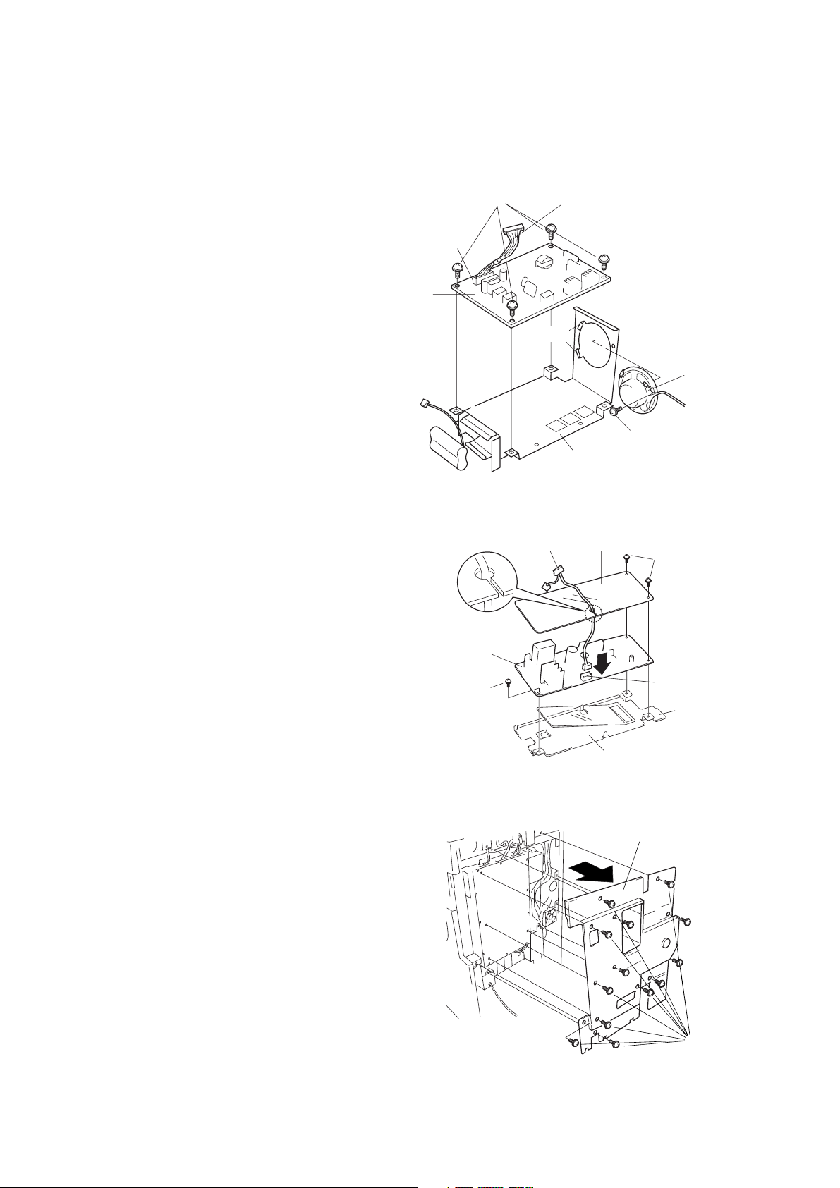
1-3-10 Installing the Facsimile System (option)
Procedure
1. Fit the battery pack into the NCU retainer as
shown in the illustration.
2. Fit the speaker onto the two catches on the
NCU retainer, and fasten it into place with
one M3 × 06 chrome binding screw.
3. Fasten the NCU board to the NCU retainer
with four M3 × 06 chrome binding screws.
4. Connect the NCU cable to connector CN1 on
the NCU board.
NCU board
M3 × 06 chrome
binding screws
Connector
CN1
2BH/J
NCU cable
Catches
Speaker
5. Adhere the lower-sheet to the auxiliary power
source retainer.
6. Fasten the auxiliary power source PCB,
together with the upper-sheet, to the auxiliary
power source retainer, using three M3 × 06
chrome binding screws.
7. Pass the FAX-PCB-Power cable through the
cutout in the upper-sheet, and connect it to
connector CN1 on the auxiliary power source
PCB.
8. Remove 13 screws and take off the rear
cover.
Battery pack
FAX-PCB-Power cable
Auxiliary power
source PCB
M3 × 06 chrome
binding screw
M3 × 06 chrome binding screw
NCU retainer
Figure 1-3-64
Upper-sheet
M3 × 06 chrome
binding screws
Connector CN1
Auxiliary power
source retainer
Lower-sheet
Figure 1-3-65
Rear cover
Figure 1-3-66
Screws
1-3-35
Page 56

2BH/J
• If the printing system is installed
9. Remove the 2 screws holding the printer
system in place, and pull the printing system
out of the shield cover.
10. Remove 13 screws and take off the shield
cover.
Printer system
Screws
Figure 1-3-67
Shield cover
11. Move the film out of the way to the left, and
fasten the fax board into place using six M3 ×
06 chrome binding screws.
Film
Figure 1-3-68
Fax board
Figure 1-3-69
Screws
M3 × 06 chrome
binding screws
1-3-36
Page 57

2BH/J
12. Fasten the NCU unit into place from the
bottom with two M3 × 06 chrome binding
screws.
13. Connect the three connectors from the NCU
board to the corresponding connectors on the
fax board, as follows:
• Speaker 2-pin connector → CN7
• NCU board connector → CN3
• Battery connector → CN6
14. Connect the three positive connectors on the
power board to the corresponding connectors
on the auxiliary power source PCB, as
follows.
• White positive connector → TB1 (white)
• Green positive connector → TB2 (green)
• White positive connector → TB3
15. Connect the FAX-PCB-Power cable to
connector on the auxiliary power source PCB.
CN6
CN7
Speaker
2-pin connecto
NCU board
connector
CN3
Battery
connector
White positive
connector
NCU board
NCU unit
M3 × 06 chrome
binding screws
Figure 1-3-70
Auxiliary power
source PCB
FAX-PCB-Power
cable
16. Fit the catch on the auxiliary power unit into
the mount hole in the copier, and fasten the
auxiliary power unit into place with one M3 ×
06 chrome binding screw.
Green positive
connector
TB1
TB3
TB2
White positive
connector
Figure 1-3-71
Connector
M3 × 06 chrome
binding screw
Catch
Mount hole
Figure 1-3-72
1-3-37
Page 58

2BH/J
17. Through the opening of controller-box above
the speaker, connect the FAX-PCB-Power
cable on the auxiliary power source PCB to
connector CN8 on the fax board.
18. Connect the 2-pin connector to the 2-pin
connector with green cable.
19. Unlock CN1 on the fax board by pulling its
connector housing.
20. Hold the fax cable with its conductive side
facing up, insert it into connector CN1, then
push the housing back in to lock the
connector.
21. Hold the other end of the fax cable with its
conductive side facing down, and connect it
to connector CN44 on the main PCB. (Pull
the CN44 housing out to release the
connector lock, then insert the cable, and
then push the housing back in.)
Important: Be sure to push the fax cable all
the way in, and be sure that the connection is
straight. A poor connection may result in a
variety of problems.
Connector CN8
FAX-PCB-Power cable
Fax cable
Fax board
Figure 1-3-73
Connector CN44
2-pin connector
with green cable
2-pin connector
Auxiliary power source PCB
CN44
CN1
Important: The Memory module DIMM (8MB)
must be installed onto the fax board. Please be
sure that you do not install it onto the main PCB.
22. Insert the Memory module DIMM (8MB) at an
angle into the memory slot on the fax board.
23. Push the free end of the module down toward
the board.
1-3-38
Fax board
Figure 1-3-74
Memory slot
Figure 1-3-75
Connector CN1
Memory module
DIMM (8MB)
Page 59
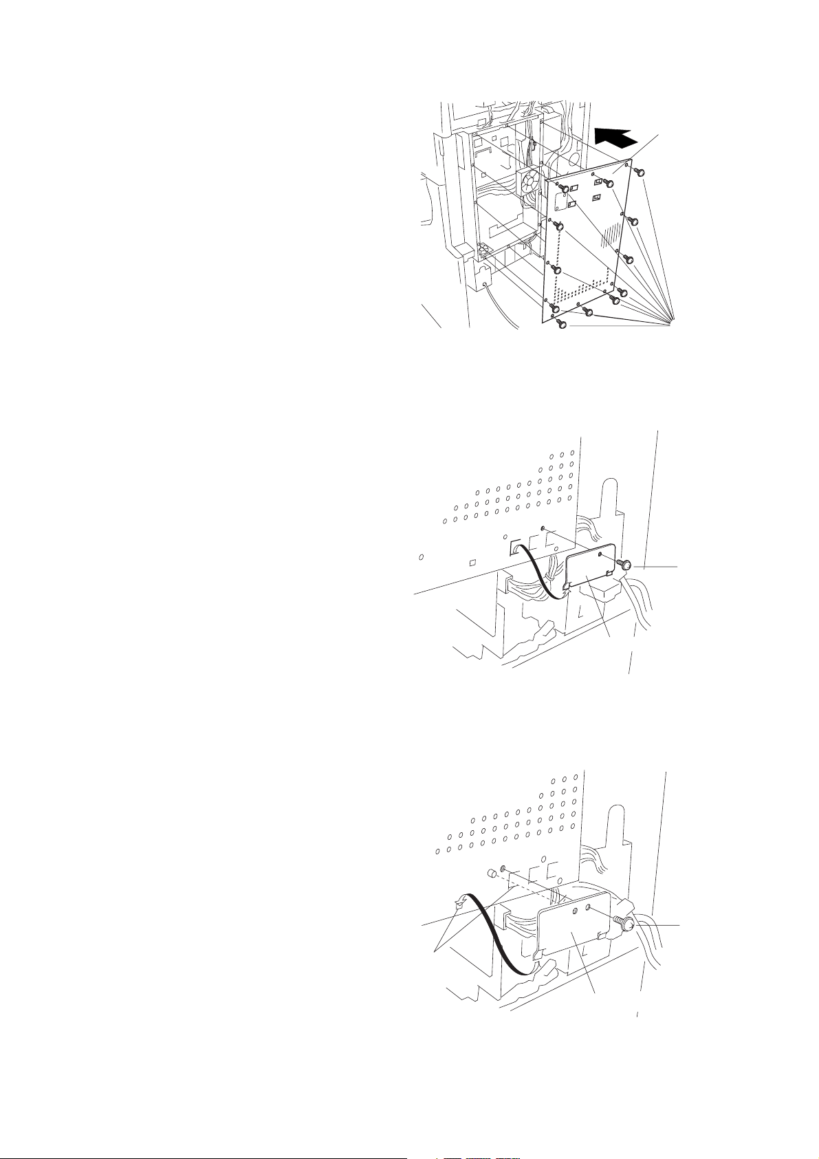
24. Fasten the shield cover into place with 13
screws.
25. Remove 1 screw and take off the modular
cover.
2BH/J
Shield cover
Screws
Figure 1-3-76
26. Hang the modular cover onto the holes on the
shield cover, and fasten it into place with 1
screw.
Screw
Modular cover
Figure 1-3-77
Screw
Holes
Modular cover
Figure 1-3-78
1-3-39
Page 60
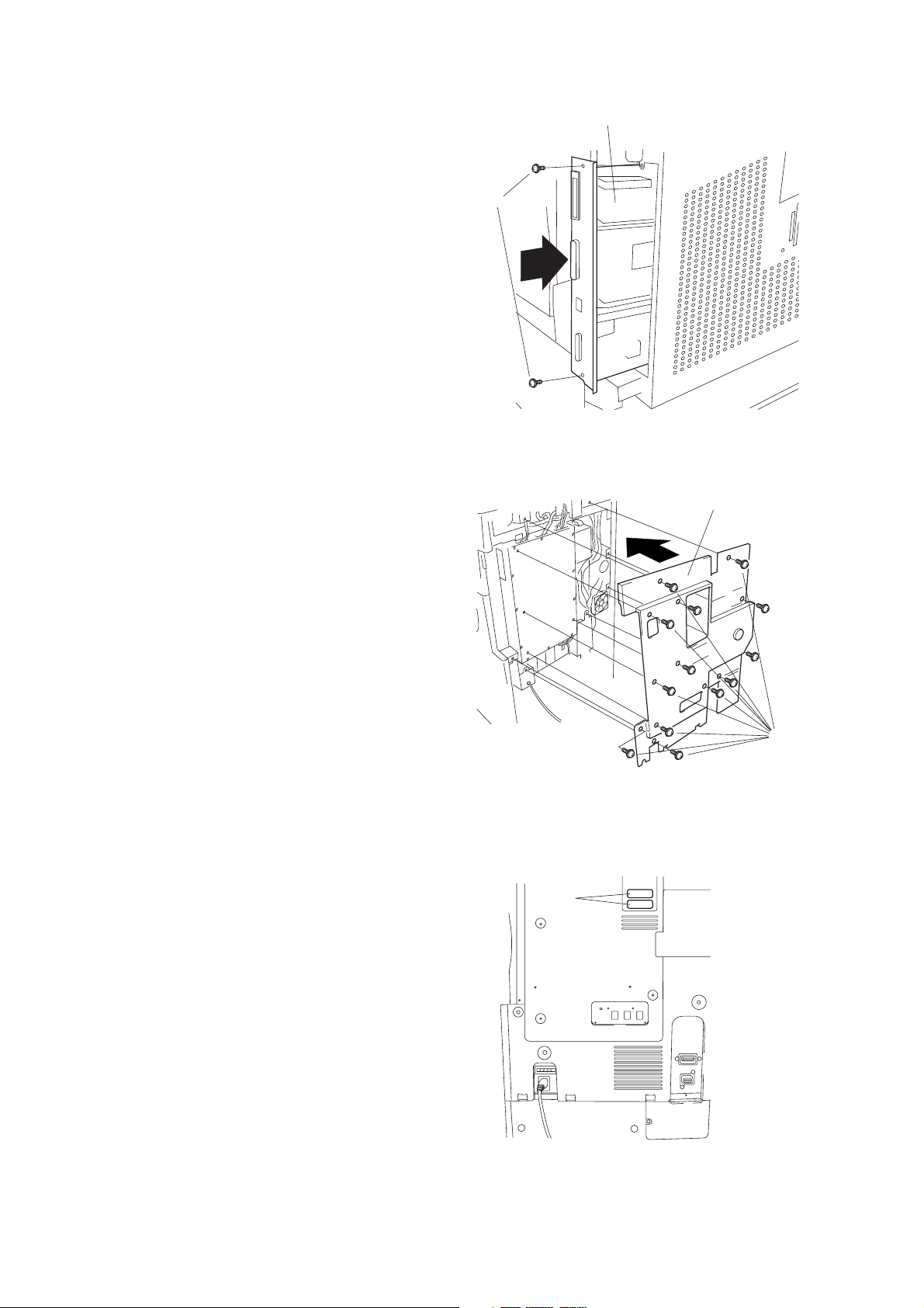
2BH/J
• If the printing system was installed
27. Reinstall the printing system into the shield
cover, fastening it into place with 2 screws.
28. Reattach the rear cover with 13 screws.
Printing system
Screws
Figure 1-3-79
Rear cover
29. Adhere the certification labels to the rear
cover at the locations indicated in the
illustration (only 120 V Spac.).
Screws
Figure 1-3-80
Certification
labels
Figure 1-3-81
1-3-40
Page 61

30. Take the power label from the fax-kit label
sheet, and adhere it to the copier directly
under the main switch.
2BH/J
Main switch
Power label
Figure 1-3-82
31. Take the alphabet labels from the fax-lit label
sheet, and adhere them above the
corresponding numeric keys on the operation
panel.
• In Asia, use the “PQRS TUV WXYZ” label,
and do not use the “PRS TUV WXZ” and
“OPER” labels.
32. Connect the L terminal to the phone circuit
using a modular connector cable.
Important: On 120 V systems, use the
included modular connector cable to make
the connection.
Alphabet labels
1
4756
PQRS TUV
Management
ABC DEF
23
OPER
0
Interrupt
Reset
MNOJKL
S
WXYZ
98
Start
Figure 1-3-83
L terminal
Stop/
Clear
Energy Sever
Figure 1-3-84
L
Modular connector
cable
1-3-41
Page 62

2BH/J
Initialization procedure after installation of facsimile system
1. Insert the copier power plug to the wall outlet
and turn the main switch on.
2. Run maintenance item U601.
3. Enter a destination code using the numeric
keys (refer to the destination code list) and
then press the start key.
* Enter a destination code with three digits.
Code
000
009
080
084
088
108
126
136
137
152
156
4. Enter the OEM code (000) and then press the
start key.
5. Confirm that the display is changed as shown
in the illustration.
* At the position of @, the version number of
the software is displayed.
Destination
Japan
Australia
Hong Kong
Indonesia
Israel
Malaysia
New Zealand
Peru
Philippines
Middle East
Singapore
Code Code
159
South Africa
169
Thailand
181
U.S.A.
242
South America
243
Saudi Arabia
253
CTR21 (European nations)
Netherlands
Destination Destination
253
Sweden
France
Austria
Switzerland
Belgium
Denmark
Italy
Germany
Spain
U.K.
254
INI. KEEP DATA
COMPLETED XXX 000
INI. KEEP DATA
COMPLETED V@.@@
Finland
Portugal
Ireland
Norway
Taiwan
6. Press the cursor key to change the display to
maintenance item U602.
7. Press the start key and confirm that the
display is changed as shown in the
illustration.
* At the position of @, the version number of
the software is displayed.
8. After completing the installation, run a
communications test to confirm that the fax
system is working correctly.
SELECT THE MAINTENANCE NUMBER.
Initial keep data U601
Figure 1-3-85
INI. SHIP DATA
COMPLETED XXX 000
INI. SHIP DATA
COMPLETED V@.@@
SELECT THE MAINTENANCE NUMBER.
Initial ship data U602
Figure 1-3-86
1-3-42
Page 63
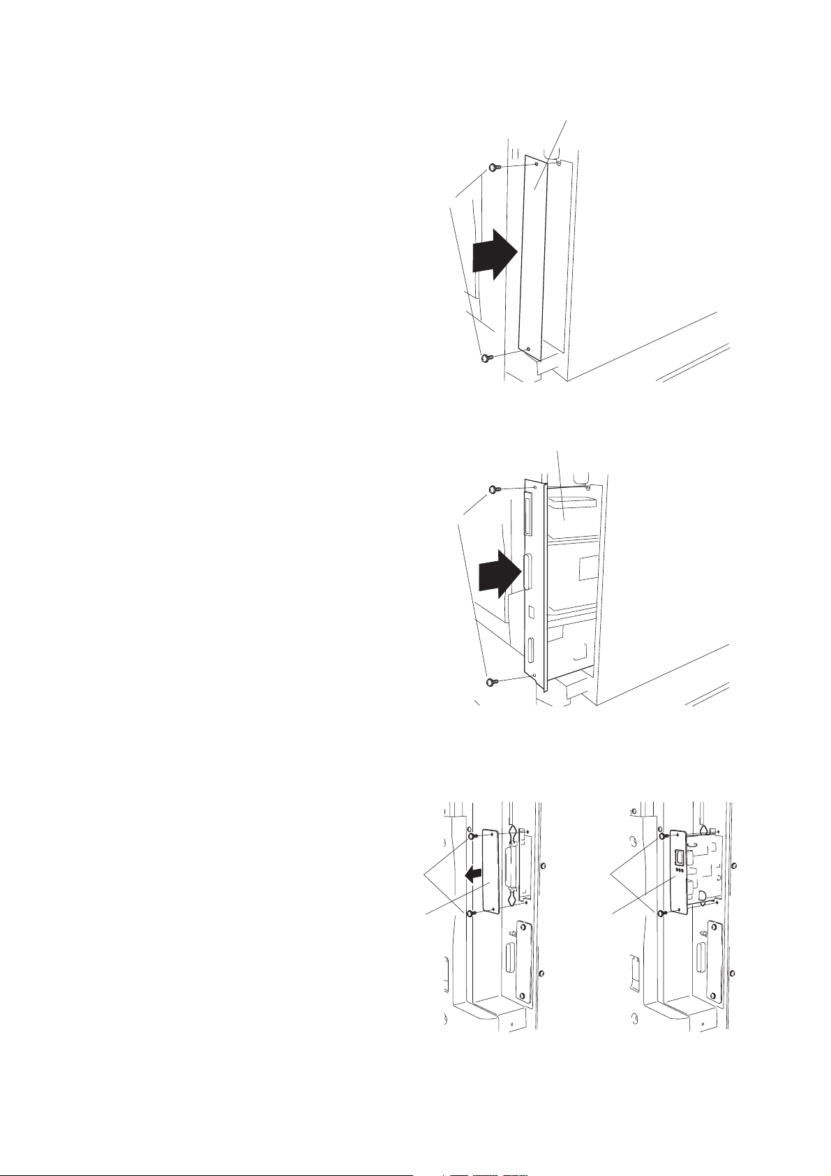
2BH/J
1-3-11 Installing the Printing System (option)
Procedure
1. Remove 2 screws and take off the cover.
2. Push the printing system all the way in along
the rails, and fasten it with 2 screws.
Cover
Screws
Figure 1-3-87
Printing system
Install the (optional) network printer board.
3. Remove 2 screws and take off the cover.
4. Push the network printer board all the way in
along the rails, and fasten it with 2 screws.
Screws
Cover
Screws
Figure 1-3-88
Screws
Netwark
printer
board
Figure 1-3-89
1-3-43
Page 64

2BH/J
Install the (optional) hard disk.
5. Remove 2 screws and take off the cover.
6. Push the hard disk all the way in along the
rails, and fasten it with 2 screws.
Installing the Optional Bar-Code Reader
7. Fasten the serial connector in place with 2
screws.
8. Tie the excess cord with the two bands, so
that the free cord length comes to about 1
meter.
9. Peel off the backing from one of the clamps,
adhere the clamp to the copier at the position
shown in the illustration, and pass the wire
though the clamp.
• If a wing tray is installed, attach the other
clamp to the wing tray and pass the wire
through both clamps.
Cover
Screws
Hard desk
Screws
Figure 1-3-90
Clamp
Wing tray
Cramps
Serial connector
Installing the Optional Memory DIMM
10. Remove the printing system, and insert the
optional memory DIMM firmly into either of
the memory slots. Push the DIMM firmly into
the slot so that the two hooks (one hook at
each end of the slot) snap closed.
• The board provides two DIMM slots, and can
accept up to two optional DIMMs. If installing
a single DIMM, you can use either slot.
Bands
Hooks
Figure 1-3-91
Option mermory
DIMM
Memory
slots
Screws
Hooks
1-3-44
Figure 1-3-92
Page 65
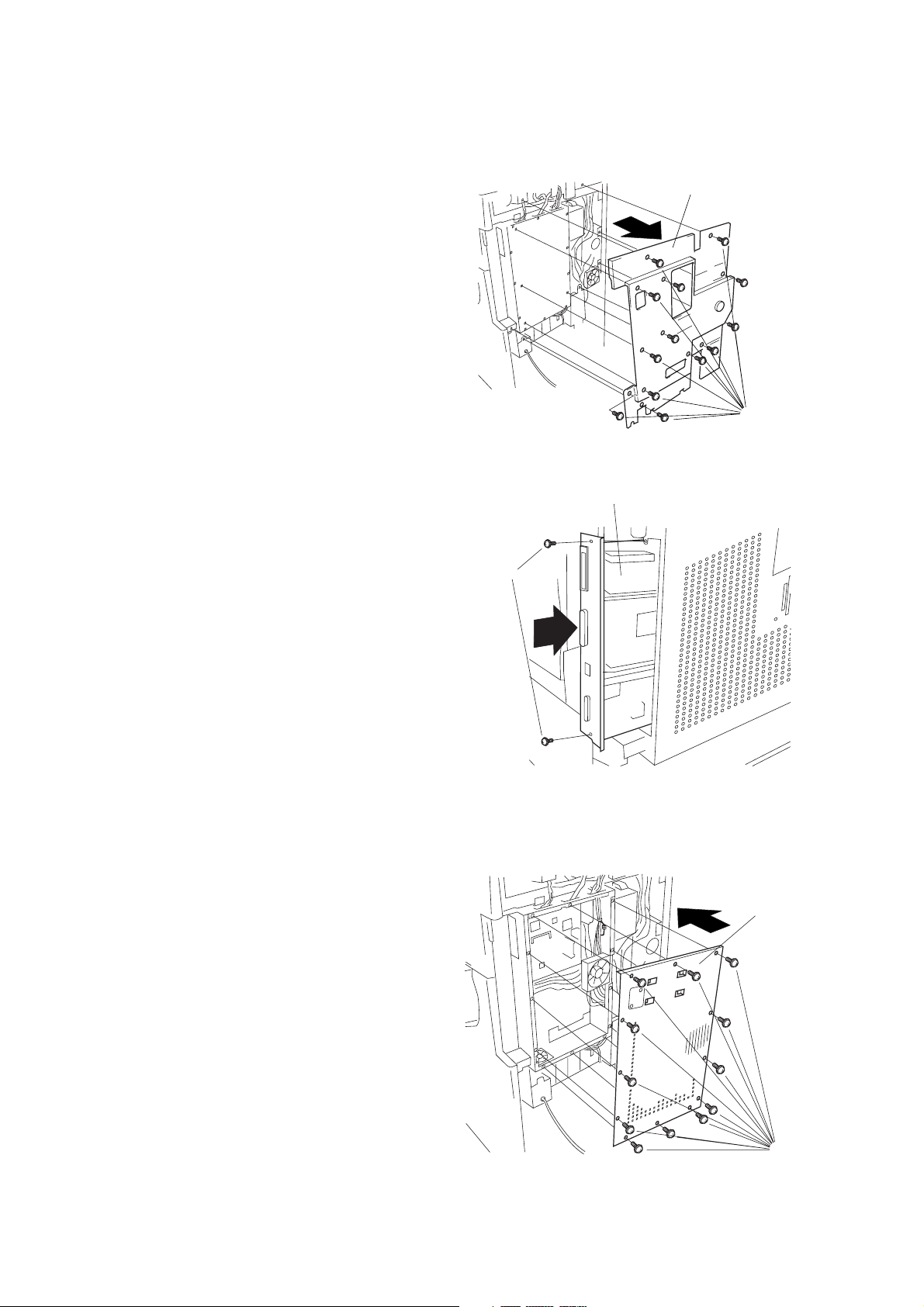
1-3-12 Installing the Scanning System (option)
Procedure
1. Remove 13 screws and take off the rear
cover.
2BH/J
Rear cover
Screws
Figure 1-3-93
• If the printing system is installed
2. Remove the 2 screws holding the printer
system in place, and pull the printing system
out of the shield cover.
3. Remove 13 screws and take off the shield
cover.
Printer system
Screws
Figure 1-3-94
Shield cover
Figure 1-3-95
Screws
1-3-45
Page 66
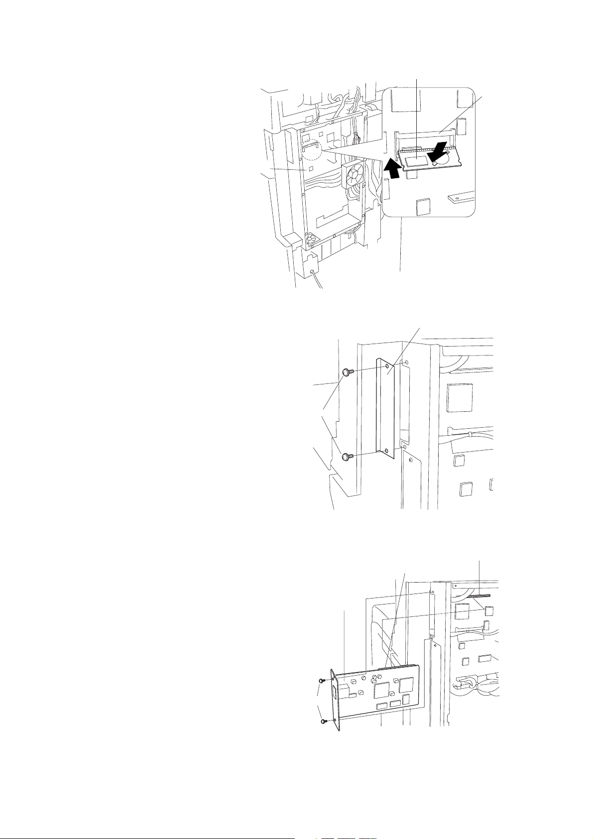
2BH/J
4. Insert the RTC board at an angle into the
RTC board slot on the main PCB.
5. Push the free end of the RTC board down
toward the fax board.
6. Remove 2 screws, and take off the cover.
RTC board
RTC board slot
Main PCB
Figure 1-3-96
Cover
7. Firmly push connector CN1 on the scanner
board all the way into connector CN50 on the
main PCB.
8. Fasten the scanner board with 2 screws.
Screws
Figure 1-3-97
Connector CN50
Connector CN1
Scanner board
Screws
1-3-46
Figure 1-3-98
Page 67

9. Fasten the shield cover into place with 13
screws.
2BH/J
Shield cover
Screws
Figure 1-3-99
• If the printing system was installed
10. Reinstall the printing system into the shield
cover, fastening it into place with 2 screws.
11. Reattach the rear cover with 13 screws.
Printing system
Screws
Figure 1-3-100
Rear cover
Figure 1-3-101
Screws
1-3-47
Page 68

2BH/J
1-3-13 Installing the duplex unit (option)
Preparation
1. Open the conveying cover.
2. Remove the screw from the front and rear
struts respectively to remove the struts and
remove the conveying cover in the horizontal
direction.
Conveying cover
Screws
Struts
Conveying cover
3. Insert the nut plates into the paper conveying
bases.
4. Raise the release lever of the conveying unit,
open the conveying unit a little, and hang the
hook sections in the front and rear of the
duplex unit on the shaft of the conveying unit.
5. Secure the duplex unit using the four M3 × 10
bronze binding screws.
Duplex unit
M3 × 10
bronze binding screws
Figure 1-3-102
Paper conveying base
Nut plates
Figure 1-3-103
Hook
Paper
conveying base
Shaft
Conveying unit
1-3-48
Release lever
M3 × 10
bronze binding screws
Figure 1-3-104
Page 69

6. Insert the 8-pin connector of the duplex unit
into the groove of the housing and pull out the
harness.
7. Connect the 8-pin connector of the duplex
unit to the connector of the copier and
arrange wiring so that the harness is placed
down.
2BH/J
Duplex unit
Connector
Groove
8. Insert the removed conveying cover in the
horizontal direction and reattach the front and
rear struts using the screw respectively.
9. Close the conveying cover.
Conveying
cover
8-pin connector
Conveying
cover
Hamess
Figure 1-3-105
Screws
Struts
10. Connect the copier power plug to the wall
outlet and turn the copier main switch on.
11. Run maintenance item U034 to adjust the
center line for duplex copying (see page 1-6-
12).
Figure 1-3-106
1-3-49
Page 70

2BH/J
1-3-14 Installing the built-in finisher (option)
Preparation
1. Remove the two screws and then remove the
upper left cover.
Upper left cover
Screws
Figure 1-3-107
2. Open the conveying cover and the front
cover.
3. Loosen the two screws on the left side and
the screw on the front side, open the hook on
the right side, and remove the left front cover.
4. Close the conveying cover and the front
cover.
5. Remove the two screws and then remove the
ejection cover with the mounting plate.
Left front cover
Screws
Figure 1-3-108
Ejection cover
Hook
Screw
1-3-50
Screws
Figure 1-3-109
Page 71

6. Remove the two screws and then remove the
inner ejection cover.
2BH/J
Inner ejection
cover
Screws
7. Insert the transfer unit into the copier from the
front side and slide it to the left.
Secure the unit using two +TP-A bronze
screws M3 × 05 and the pin that has been
fitted to the transfer unit.
Transfer unit
Figure 1-3-110
+TP-A bronze screw M3 × 05
+TP-A bronze screw M3 × 05
Figure 1-3-111
Pin
8. Insert the metal hook of the transfer unit into
the oblong hole of the frame of the copier and
secure it using a +TP-A bronze screw M3 ×
05.
* Insert the projection of the frame into the
hole of the metal hook to position the hook.
* Arrange the cable to position it under the
metal fittings.
Metal fittings
+TP-A bronze
screw M3 × 05
Cable
Figure 1-3-112
Hook
Oblong hole
Hole
Projection
1-3-51
Page 72

2BH/J
9. Remove a screw, turn the metal fittings
upward, and fit the screw again to the lower
hole.
10. Insert the intermediate tray and connect the
connector (white) of the intermediate tray to
the transfer unit. Connect the connectors
(gray) to the connectors of the copier as
shown in the illustration.
Connect the gray connector with more pins to
the upper connector and the gray connector
with less pins to the lower connector.
Metal fittings
Screw
Screw
Figure 1-3-113
Connector (white)
Intermediate tray
Connector (gray)
11. Attach the intermediate tray to the copier as
shown in the illustration so that the right and
left pins of the intermediate tray are
positioned to the recessed portions of the
copier and the transfer unit.
Transfer unit
1-3-52
Recessed portion
Figure 1-3-114
Pin
Recessed porton
Intermediate tray
Figure 1-3-115
Page 73
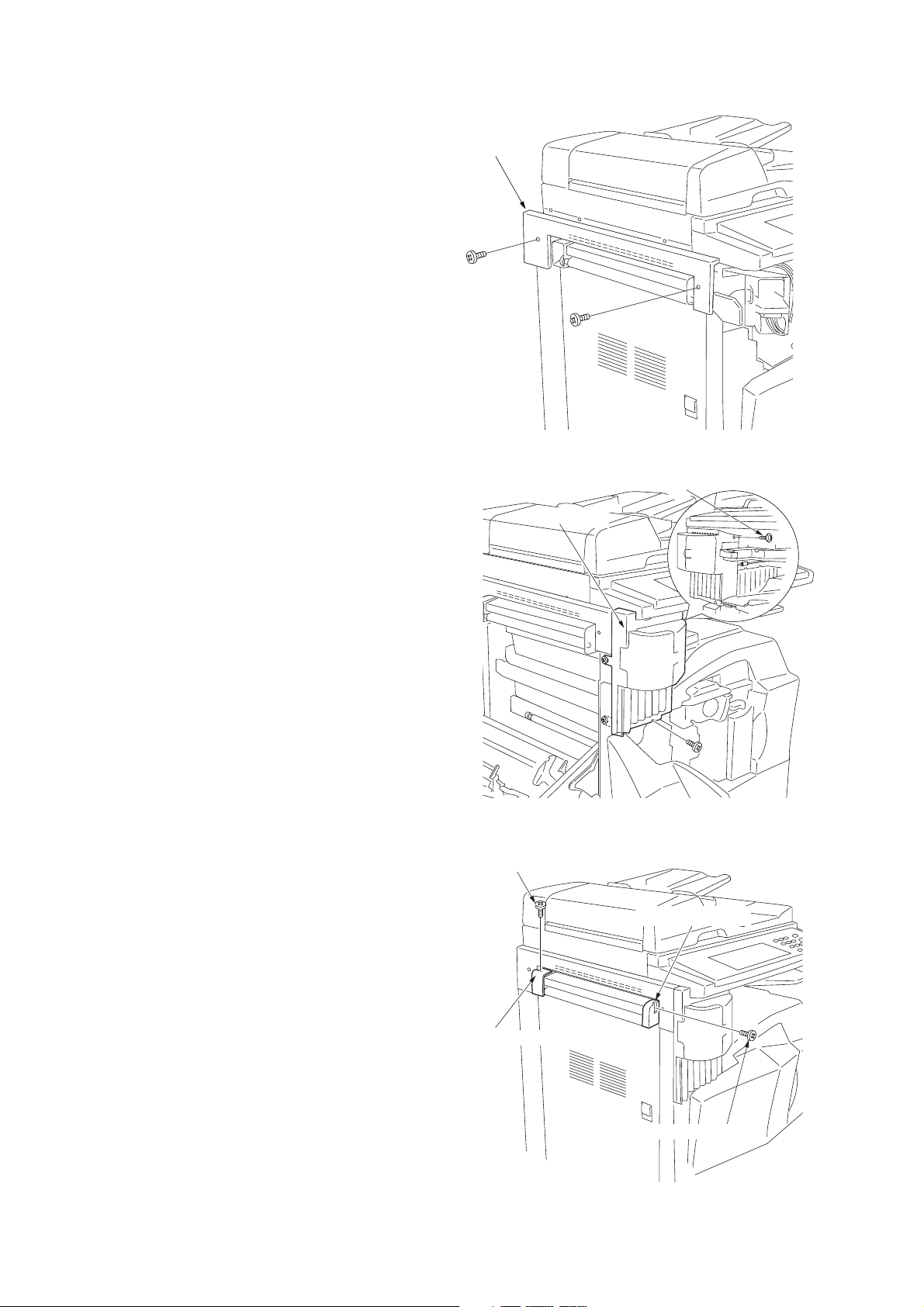
12. Attach the large ejection cover using the two
screws that have secured the upper left cover.
2BH/J
Large ejection
cover
Figure 1-3-116
13. Open the front cover and the conveying
cover.
14. Attach the staple cover.
* Tighten the two screws on the left side to
secure the cover with the copier, secure the
front side using the screw that has been
removed in step 3, and secure the right side
using a +TP-A chrome screw M3 × 05.
15. Attach the front ejection cover and the rear
ejection cover using a +TP-A chrome screw
M3 × 05 each.
+TP-A chrome screw M3 × 05
Staple cover
Figure 1-3-117
+TP-A chrome screw M3 × 05
Front ejection cover
Rear ejection cover
+TP-A chrome screw M3 × 05
Figure 1-3-118
1-3-53
Page 74

2BH/J
16. Attach the copy tray.
Copy tray
Figure 1-3-119
17. Insert the staple cartridge into the stapler.
18. Insert the power plug of the copier into an
outlet and turn the main switch on.
19. Select the staple mode and make a stapled
copy to check that stapling is performed
properly.
Staple cartridge
Figure 1-3-120
1-3-54
Page 75
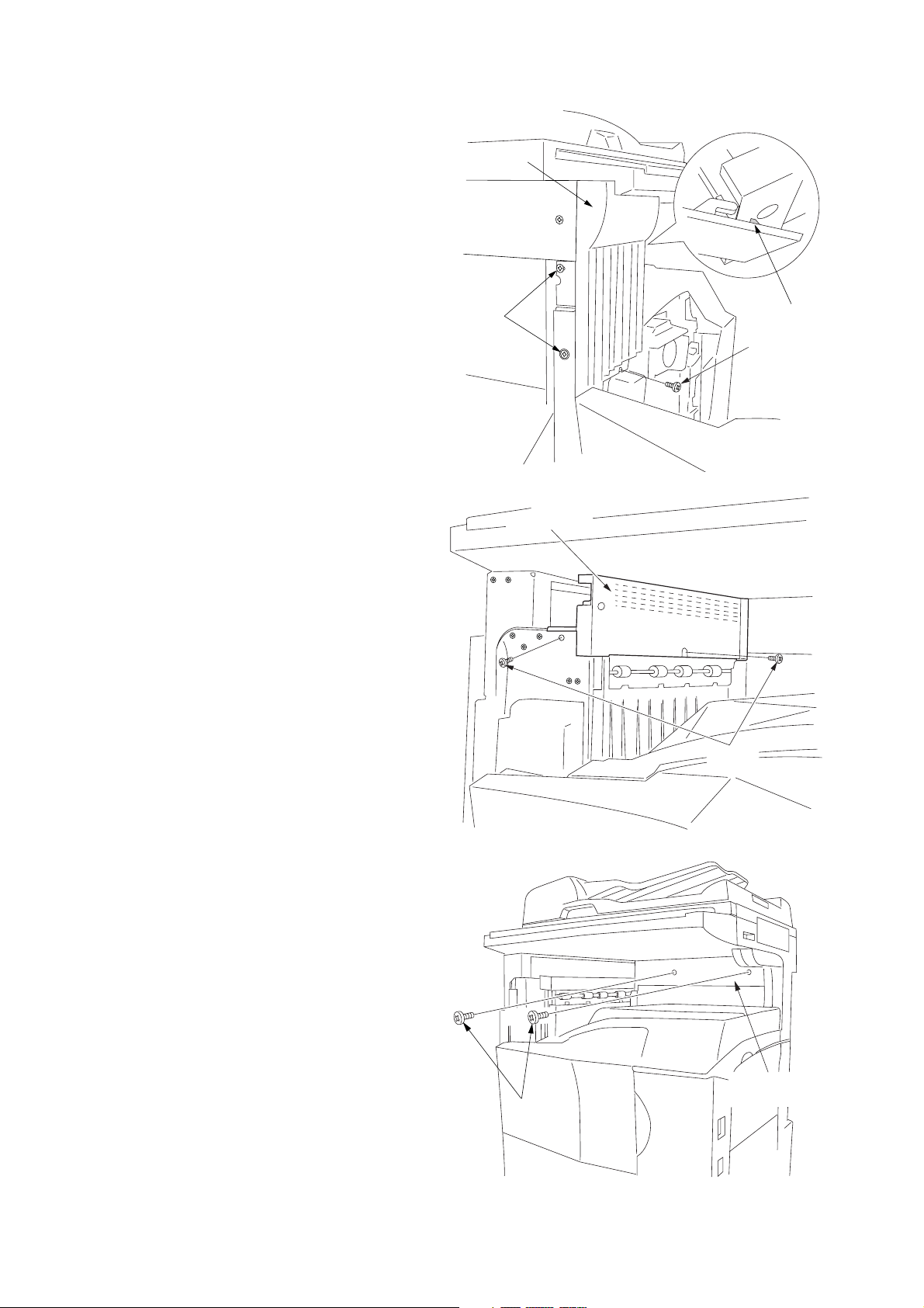
1-3-15 Installing the job separator (option)
2BH/J
Preparation
1. Open the conveying cover and the front
cover.
2. Loosen the two left screws on the left side,
remove the screw on the front side, open the
hook on the right side, and remove the left
front cover.
3. Close the conveying cover and the front
cover.
4. Remove the two screws and remove the
ejection cover with the mounting plate.
Left front
cover
Screws
Hook
Screw
Figure 1-3-121
Ejection cover
5. Remove the two screws and then remove the
inner ejection cover.
Screws
Screws
Figure 1-3-122
Inner ejection
cover
Figure 1-3-123
1-3-55
Page 76
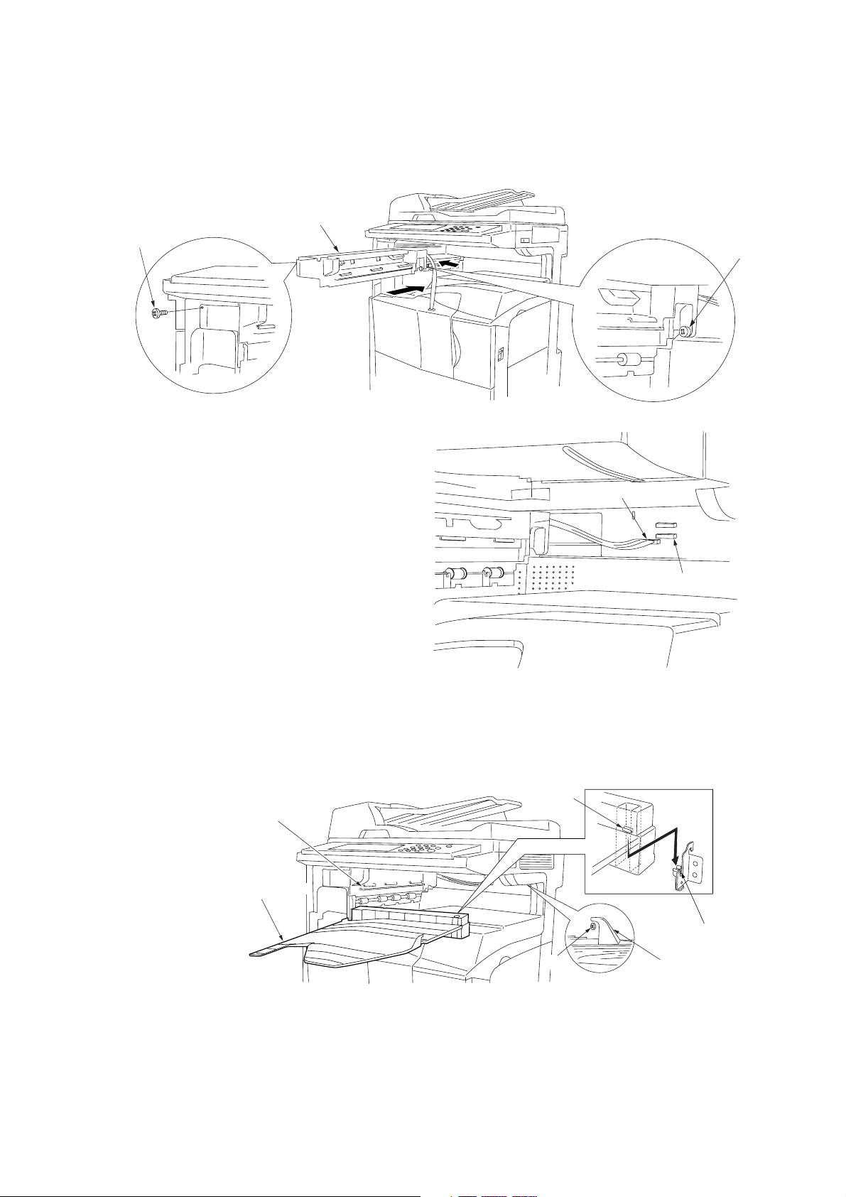
2BH/J
6. Insert the job separator into the copier from
the front side and slide it to the left. Secure
the front side using a +TP-A bronze screw M3
× 05 and the rear side using a pin.
* Check to see if the branch pressure lever on
the rear side of the job separator has
lowered.
Job separator
+TP-A bronze screw
M3 × 05
Pin
7. Connect the connector of the job separator to
the lower connector of the copier.
8. Attach the job separator tray to the rail of the
job separator by sliding it from the front side.
* Insert the fitting section on the right side of
the job separator tray into the recessed
portion of the copier.
* Put the hook on the right side onto the pin.
9. Reattach the left front cover in its original
position.
Rail
Figure 1-3-124
Connector
Connector of the copier
Figure 1-3-125
Fitting section
Job separator
tray
10. Insert the power plug of the copier into an
outlet and turn the main switch on.
11. Set the “copy ejection location” of the
machine default settings to job separator.
12. Make a test copy to check that a copy is
ejected to the job separator tray.
1-3-56
Pin
Figure 1-3-126
Recessed portion
Hook
Page 77
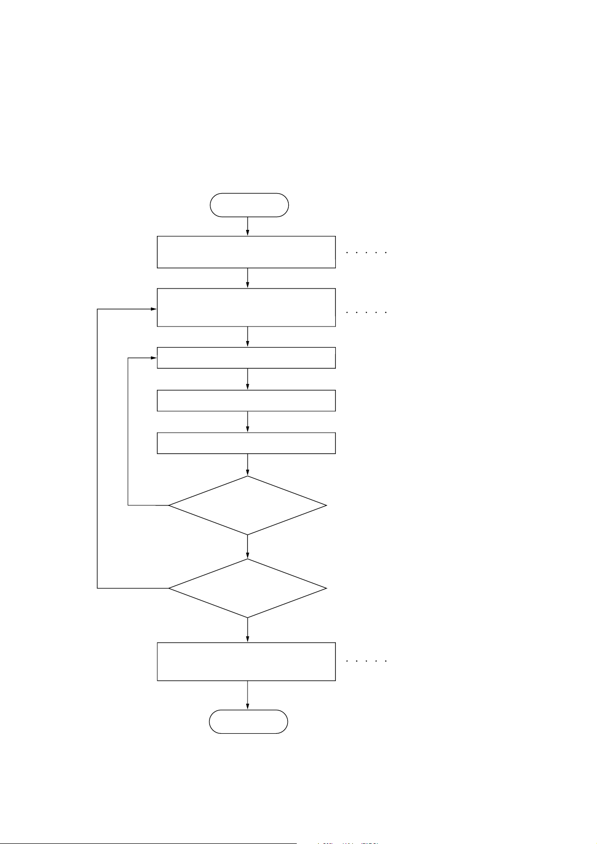
1-4-1 Maintenance mode
The copier is equipped with a maintenance function which can be used to maintain and service the machine.
(1) Executing a maintenance item
Start
2BH/J
Yes
Enter “10871087” using
the numeric keys.
Enter the maintenance item
number using the cursor up/down keys
or numeric keys.
Press the start key.
The selected maintenance item is run.
Press the stop/clear key.
Repeat the same
maintenance item?
Maintenance mode is entered.
The maintenance item is
selected.
Yes
No
Run another maintenance
item?
No
Enter “001” using the cursor
up/down keys or numeric keys
and press the start key.
End
Maintenance mode is exited.
1-4-1
Page 78

2BH/J-1
(2) Maintenance mode item list
Section
General
Initialization
Drive, paper
feed, paper
conveying and
cooling system
Optical
Item
No. setting*
U000 Outputting an own-status report —
U001 Exiting the maintenance mode —
U003 Setting the service telephone number
U004 Setting the machine number 000000
U005 Copying without paper —
U019 Displaying the ROM version —
U020 Initializing all data —
U021 Initializing counters and mode settings —
U022 Initializing data for optical system —
U030 Checking motor operation —
U031 Checking switches for paper conveying —
U032 Checking clutch operation —
U033 Checking solenoid operation —
U034 Adjusting the print start timing
• Adjusting the leading edge registration
• Adjusting the center line
U035 Setting folio size
• Length 330
• Width 210
U038 Checking the copier cover switch —
U051 Adjusting the amount of slack in the paper
• Regist data
• Feed data
U053 Performing fine adjustment of the motor speed
• Drive motor 7
• Eject motor 7
• Polygon motor 0
U060 Adjusting the scanner input properties 12
U061 Turning the exposure lamp on —
U063 Adjusting the shading position 0
U065 Adjusting the scanner magnification
• Main scanning direction/auxiliary scanning direction
U066 Adjusting the leading edge registration for scanning an original on the
contact glass
U067 Adjusting the center line for scanning an original on the contact glass
U068 Adjusting the scanning position for originals from the DF 0
U070 Adjusting the DF magnification 0
U071 Adjusting the DF scanning timing
• DF leading edge registration/DF trailing edge registration 0
U072 Adjusting the DF center line 0
U073 Checking scanner operation —
U074 Adjusting the DF input light luminosity 1
U087 Turning the DF scanning position adjust mode on/off On
U088 Setting the input filter (moiré reduction mode) Off
U089 Outputting a MIP-PG pattern —
U091 Checking shading —
U092 Adjusting the scanner automatically —
U093 Setting the exposure density gradient
Maintenance item contents
• Text and photo/text/photo/text in fax/photo in fax mode 0/0/0/2/3
U099 Checking and setting the original size detection sensor —
* Initial setting for executing maintenance item U020
1-4-2
Initial
***************
—
—
—
—
—
—
—
Page 79

2BH/J-1
Section
High voltage
Developing
Fixing and
cleaning
Operation
panel and
support
equipmen
Mode setting
Item
No. setting*
U100 Checking the operation of main high voltage 184
U101 Setting high voltages
• Developing bias AC component frequency at image formation
• Developing bias AC component duty at image formation
•
Developing shift bias potential at image formation 0
• Transfer control voltage
Maintenance item contents
Initial
0
0
120
U109 Drum type display —
U110 Checking/clearing the drum count —
U112 Setting toner refresh operation
• Time of toner refreshment 120
• Developing bias on time 700
U113 Operating the drum refreshment —
U130 Initial setting for the developer —
U144 Setting toner loading operation MODE2
U150 Checking sensors and switches for toner —
U157 Checking/clearing the developing drive time —
U158 Checking/clearing the developing count —
U161 Setting the fixing control temperature
• Control temperature during copying
• Primary stabilization fixing temperature
• Secondary stabilization fixing temperature
U162 Stabilizing fixing forcibly —
U163 Resetting the fixing problem data —
U165 Checking/clearing fixing counts —
U196 Turning the fixing heater on —
U199 Checking the fixing temperature —
U200 Turning all LEDs on —
U201 Initializing the touch panel —
U202 Setting the KMAS host monitoring system —
U203 Operating DF separately —
U204 Setting the presence or absence of a key card or key counter —
U206 Setting the presence or absence of the coin vender —
U207 Checking the operation panel keys —
U208 Setting the paper size for the large paper deck A4
U211 Setting DF type —
U217 Setting 81/2" × 13" paper —
165
110
165
U236 Setting the limit for the ejection section of the built-in finisher —
U237 Setting finisher stack quantity —
U243 Checking the operation of the DF motors, solenoids and clutch —
U244 Checking the DF switches —
U245 Checking messages —
U246 Setting the finisher
• Amount of slack in the paper 0
• Booklet stapling position adjustment 0
• Side registration cursor stop position 0
U247 Checking the operation of large paper deck and paper feed desk —
U249 Checking the paper ejection to optional devices —
U250 Setting the maintenance cycle
U251 Checking/clearing the maintenance count —
U252 Setting the destination Japan
500000 (35 cpm)
400000 (25 cpm)
* Initial setting for executing maintenance item U020
1-4-3
Page 80

2BH/J-1
Section
Mode setting
Image
processing
Others
Item
No. setting*
U253 Switching between double and single counts Double count
U254 Turning auto start function on/off On
U255 Setting auto clear time 90
U256 Turning auto preheat/energy saver function on/off On
U258 Switching copy operation at toner empty detection
Maintenance item contents
Initial
Single mode,
70
U260 Changing the copy count timing After ejection
U264 Setting the display order of the date Inch
specifications:
MONTH-DATE-YEAR
Metric
specifications:
DATE-MONTH-YEAR
U265 Setting OEM purchaser code —
U274 Setting the laser scanner unit type 0
U330 Setting the number of sheets to enter stacking mode during sort operation —
U331 Switching the finisher eject section OFF
U332 Setting the size conversion factor —
U341 Specific paper feed location setting for printing function —
U342 Setting the ejection restriction On
U343 Switching between duplex/simplex copy mode Off
U344 Setting preheat/energy saver mode
U345 Setting the value for maintenance due indication —
ENERGY STAR
U346 Setting the sleep mode operation MODE0
U402 Adjusting margins of image printing —
U403 Adjusting margins for scanning an original on the contact glass —
U404 Adjusting margins for scanning an original from the DF —
U407 Adjusting the leading edge registration for memory image printing —
U500 Setting the limit on data size for e-mail transmission LITTLE
U501 Setting image area ON
U504 Initializing the scanner NIC —
U540 Adjusting the auxiliary scanning magnification 0
U901 Checking/clearing copy counts by paper feed locations —
U902 Checking/clearing finisher punch count
U903 Checking/clearing the paper jam counts —
U904 Checking/clearing the service call counts —
U905 Checking/clearing counts by optional devices —
U906 Resetting partial operation control —
U908 Changing the total counter value —
U910 Clearing the black ratio data —
U911 Checking/clearing copy counts by paper sizes —
U990 Checking/clearing the time for the exposure lamp to light —
U991 Checking/clearing the scanner count —
U992 Checking or clearing the printer/fax count —
U993 Outputting a VTC-PG pattern —
20000
* Initial setting for executing maintenance item U020
1-4-4
Page 81

(3) Contents of maintenance mode items
2BH/J
Maintenance
item No.
U000 Outputting an own-status report
Description
Outputs lists of the current settings of the maintenance items, and paper jam and service call occurrences.
Purpose
To check the current setting of the maintenance items, or paper jam or service call occurrences.
Before initializing or replacing the backup RAM, output a list of the current settings of the maintenance items to
reenter the settings after initialization or replacement.
Method
1. Press the start key. The screen for selecting an item is displayed.
2. Select the item to be output. The selected item is displayed in reverse.
Display Output list
MAINTENANCE List of the current settings of the maintenance modes
JAM List of the paper jam occurrences
SERVICE CALL List of the service call occurrences
3. Press the start key. The interrupt copy mode is entered and a list is output.
1
When A4/11" × 8
/2" paper is available, a report of this size is output. If not, specify the paper feed location.
When output is complete, the screen for selecting an item is displayed.
Completion
Press the stop/clear key at the screen for selecting an item. The screen for selecting a maintenance item No. is
displayed.
U001 Exiting the maintenance mode
Description
Exits the maintenance mode and returns to the normal copy mode.
Purpose
To exit the maintenance mode.
Method
Press the start key. The normal copy mode is entered.
Description
1-4-5
Page 82

2BH/J
Maintenance
item No.
U003 Setting the service telephone number
Description
Sets the telephone number to be displayed when a service call code is detected.
Purpose
To set the telephone number to call service when installing the machine.
Method
Press the start key. The currently set telephone number is displayed.
Setting
1. Enter a telephone number (up to 15 digits) using the numeric keys.
• To enter symbols such as hyphens and parentheses, select as required from the symbols displayed on
the touch panel as shown below. To move the cursor, press LEFT or RIGHT in the bottom row.
*
(
-
LEFT
2. Press the start key. The phone number is set, and the screen for selecting a maintenance item No. is
displayed.
Completion
To exit this maintenance item without changing the current setting, press the stop/clear key. The screen for
selecting a maintenance item No. is displayed.
U004 Setting the machine number
Description
Displays and changes the machine number.
Purpose
To check or set the machine number.
Method
Press the start key. The currently set machine number is displayed.
Setting
1. Enter the last six digits of the machine number using the numeric key.
Do not enter the first two digits, 3 and 7.
2. Press the start key. The machine number is set, and the screen for selecting a maintenance item No. is
displayed.
Completion
To exit this maintenance item without changing the current setting, press the stop/clear key. The screen for
selecting a maintenance item No. is displayed.
#
)
(Space)
RIGHT
Description
1-4-6
Page 83

2BH/J
Maintenance
item No.
U005 Copying without paper
Description
Simulates the copy operation without paper feed.
Purpose
To check the overall operation of the machine.
Method
1. Press the start key. The screen for selecting an item is displayed.
2. Select the item to be operated. The selected item is displayed in reverse.
Display Operation
PPC Only the copier operates.
PPC + DF Both the copier and DF operate (continuous operation).
3. Press the interrupt key. The copy mode screen is displayed.
4. Set the operation conditions required on the copy mode screen. Changes in the following settings can be
made.
• Paper feed locations
• Magnifications
• Simplex or duplex copy mode
• Number of copies: in simplex copy mode, continuous copying is performed when set to 999; in duplex
copy mode, continuous copying is performed regardless of the setting.
• Copy density
• Keys on the operation panel other than the energy saver (preheat) key
5. To control the paper feed pulley, remove all the paper in the drawers, or the drawers. With the paper
present, the paper feed pulley does not operate.
6. Press the start key. The operation starts.
Copy operation is simulated without paper under the set conditions. When operation is complete, the
screen for selecting an item is displayed.
7. To stop continuous operation, press the stop/clear key.
Completion
Press the stop/clear key at the screen for selecting an item. The screen for selecting a maintenance item No. is
displayed.
U019 Displaying the ROM version
Description
Displays the part number of the ROM fitted to each PCB.
Purpose
To check the part number or to decide if the ROM version is new from the last digit of the number.
Method
Press the start key. The last eight digits of the part number indicating the ROM version are displayed.
Display Description
MAIN Main ROM IC
MMI Operation ROM IC
LANGUAGE(Stand.) Standard language ROM IC
LANGUAGE(Option) Optional language ROM IC
MAIN BOOT Boot of main ROM IC
MMI BOOT Boot of operation ROM IC
NETWORK SCANNER Network scanner ROM IC
Description
Completion
Press the stop/clear key. The screen for selecting a maintenance item No. is displayed.
1-4-7
Page 84

2BH/J
Maintenance
item No.
U020 Initializing all data
Description
Initializes all the backup RAM on the main PCB to return to the original settings.
Purpose
Used when replacing the backup RAM on the main PCB.
Method
1. Press the start key. The screen for executing is displayed.
2. Press EXECUTE on the touch panel. It is displayed in reverse.
3. Press the start key. All data in the backup RAM is initialized, and the original settings for Japan
specifications are set.
When initialization is complete, the machine automatically returns to the same status as when the main
switch is turned on and the display language to the initial setting of English.
Completion
To exit this maintenance item without executing initialization, press the stop/clear key. The screen for selecting
a maintenance item No. is displayed.
U021 Initializing counters and mode settings
Description
Initializes the setting data other than that for adjustments due to variations between respective machines, i.e.,
settings for counters, service call history and mode settings. As a result, initializes the backup RAM according
to the specifications depending on the destination selected in U252.
Purpose
Used to return the machine settings to the factory settings.
Method
1. Press the start key. The screen for executing is displayed.
2. Press EXECUTE on the touch panel. It is displayed in reverse.
3. Press the start key. All data other than that for adjustments due to variations between machines is
initialized based on the destination setting.
Completion
Press the stop/clear key. The screen for selecting a maintenance item No. is displayed.
U022 Initializing data for optical system
Description
Initializes only the data set for the optical section.
Purpose
To be executed after replacing the scanner unit.
Method
1. Press the start key. The screen for executing is displayed.
2. Press SCANNER on the touch panel.
3. Press EXECUTE on the touch panel. It is displayed in reverse.
4. Press the start key. The data for the optical section (U060 to 067, U088 to 099, U403, U990 and U991) is
initialized.
Completion
Press the stop/clear key. The screen for selecting a maintenance item No. is displayed.
Description
1-4-8
Page 85

2BH/J
Maintenance
item No.
U030 Checking motor operation
Description
Drives each motor.
Purpose
To check the operation of each motor.
Method
1. Press the start key. The screen for selecting an item is displayed.
2. Select the motor to be operated. The selected item is displayed in reverse and the operation starts.
Display Operation
FEED Paper feed motor operates
MAIN Drive motor operates
EJECT(FW) Eject motor rotates forward
EJECT(REV) Eject motor rotates in reverse
3. To stop operation, press the stop/clear key.
Completion
Press the stop key after operation stops. The screen for selecting a maintenance item No. is displayed.
U031 Checking switches for paper conveying
Description
Displays the on-off status of each paper detection switch on the paper path.
Purpose
To check if the switches for paper conveying operate correctly.
Method
1. Press the start key. A list of the switches, the on-off status of which can be checked, are displayed.
2. Turn each switch on and off manually to check the status.
When the on-status of a switch is detected, that switch is displayed in reverse.
Display Switches
F1 Feed switch 1 (FSW1)
F2 Feed switch 2 (FSW2)
F3 Feed switch 3 (FSW3)
BYP Bypass feed switch (BYPFSW)
RES Registration switch (RSW)
EJE Eject switch (ESW)
BRA Feedshift switch (FSSW)
DUP Duplex paper conveying switch (DUPPCSW)*
JOB Job separator eject switch (JBESW)*
*Optional.
Completion
Press the stop/clear key. The screen for selecting a maintenance item No. is displayed.
Description
1-4-9
Page 86

2BH/J
Maintenance
item No.
U032 Checking clutch operation
Description
Turns each clutch on.
Purpose
To check the operation of each clutch.
Method
1. Press the start key. The screen for selecting an item is displayed.
2. Select the clutch to be operated. The selected item is displayed in reverse, and the clutch turns on for 1 s.
Display Clutches
PF1 Upper paper feed clutch (PFCL-U)
PF2 Lower paper feed clutch (PFCL-U)
PFBYP Bypass paper feed clutch (BYPPFCL)
FEED1 Feed clutch 1 (FCL1)
FEED2 Feed clutch 2 (FCL2)
FEED3 Feed clutch 3 (FCL3)
BYPF Bypass feed clutch (BYPFCL)
RES Registration clutch (RCL)
DUPF Duplex feed clutch (DUPFCL)*
*Optinal.
Completion
Press the stop/clear key. The screen for selecting a maintenance item No. is displayed.
U033 Checking solenoid operation
Description
Turns each solenoid on.
Purpose
To check the operation of each solenoid.
Method
1. Press the start key. The screen for selecting an item is displayed.
2. Select the solenoid to be operated. The selected item is displayed in reverse, and the solenoid turns on for
1 s.
Display Solenoids
TONER SOL Toner feed solenoid (TNFSOL)
BRANCH1 SOL Feedshift solenoid (FSSOL)
BRANCH2 SOL Feedshift solenoid (FSSOL)*
MAIN SW SOL Main switch turns on
*Optional.
Select MAIN SW SOL to check the operation of the main switch in auto shut off.
Completion
Press the stop/clear key. The screen for selecting a maintenance item No. is displayed.
U034 Adjusting the print start timing
Adjustment
See pages 1-6-10 and 12.
Description
1-4-10
Page 87

2BH/J
Maintenance
item No.
U035 Setting folio size
Description
Changes the image area for copying onto folio size paper.
Purpose
To prevent the image at the trailing edge, or right or left side of the paper from not being copied by setting the
actual size of the folio paper used.
Method
Press the start key. The screen for selecting an item is displayed.
Setting
1. Select the item to be set. The selected item is displayed in reverse.
2. Change the setting using the cursor up/down keys.
Display Setting Setting range Initial setting
LENGTH DATA Length 330 to 356 mm 330
WIDTH DATA Width 200 to 220 mm 210
3. Press the start key. The value is set.
Completion
Press the stop/clear key. The screen for selecting a maintenance item No. is displayed.
U038 Checking the copier cover switch
Description
Displays the on-off status of each cover switch.
Purpose
To check if the switches of covers operate correctly.
Method
1. Press the start key. A list of the switches, the on-off status of which can be checked, are displayed.
2. Open and close each cover to check the status of each switch.
When the cover is closed, the switch shall be displayed in reverse. When the cover is open, the switch shall
be displayed normally.
Display Switches
INTER LOCK SW Safty switch 1 and 2 (SSW1 and 2)
FRONT COVER Front cover switch (FRCSW)
LEFT1 COVER Conveying cover switch (CCSW)
LEFT2 COVER Side cover switch (SCSW)
Completion
Press the stop/clear key. The screen for selecting a maintenance item No. is displayed.
U051 Adjusting the amount of slack in the paper
Adjustment
See page 1-6-14.
Description
1-4-11
Page 88

2BH/J
Maintenance
item No.
U053 Performing fine adjustment of the motor speed
Description
Performs fine adjustment of the speeds of the motors.
Purpose
Used to adjust the speed of the respective motors when the magnification is not correct.
Method
Press the start key. The screen for selecting an item is displayed.
Setting
1. Select the item to be set. The selected item is displayed in reverse.
2. Change the setting using the cursor up/down keys.
Display Description Setting range Initial setting
MAIN MOTOR Drive motor speed adjustment 0 to +14 7
EJECT MOTOR Eject motor speed adjustment 0 to +14 7
POLYGON MOTOR Polygon motor speed adjustment -20 to +20 0
MAIN MOTOR /EJECT MOTOR
Increasing the setting makes the image longer in the auxiliary scanning direction, and decreasing it makes
the image shorter in the auxiliary scanning direction.
POLYGON MOTOR
Increasing the setting makes the image longer in the main scanning direction and shorter in the auxiliary
scanning direction; decreasing the setting makes the image shorter in the main scanning direction and
longer in the auxiliary scanning direction.
EJECT MOTOR
Normally no change is necessary but this can be used as countermeasures against wrinkles (waving) of
paper.
3. Press the start key. The value is set.
Interrupt copy mode
While this maintenance item is being performed, a VTC pattern shown below is output in interrupt copy mode.
Correct values for an A3/11" × 17" output are:
A = 300 ± 1.5 mm
B = 260 ± 1.0 mm
Description
1-4-12
Figure 1-4-1
Adjustment
1. Output an A3/11" × 17" VTC pattern in interrupt mode.
2. Measure A and B on the VTC pattern (Figure 1-4-1), and perform the following adjustments if they are
different from the correct sizes:
A: Drive motor speed adjustment
B: Polygon motor speed adjustment
Completion
Press the stop/clear key at the screen for selecting an item. The screen for selecting a maintenance item No. is
displayed.
Page 89

2BH/J
Maintenance
item No.
U060 Adjusting the scanner input properties
Description
Adjusts the image scanning density in text, text and photo, or photo mode.
Purpose
Used when the entire image appears too dark or light.
Method
Press the start key. The screen for executing is displayed.
Setting
1. Change the setting using the cursor up/down keys.
Descrition Setting range Initial setting
Image scannnig density 0 to +24 12
Increasing the setting makes the density lower, and decreasing it makes the density higher.
2. Press the start key. The value is set.
Interrupt copy mode
While this maintenance item is being performed, copying from an original can be made in interrupt copy mode.
Completion
Press the stop/clear key at the screen for selecting an item. The screen for selecting a maintenance item No. is
displayed.
Caution
The following settings are also reset to the initial values by performing this maintenance item:
• Exposure density gradient set in maintenance mode (U093)
• Exposure set in the copy default item of the copier management mode
U061 Turning the exposure lamp on
Description
Turns the exposure lamp on.
Purpose
To check the exposure lamp.
Method
1. Press the start key. The screen for executing is displayed.
2. Press the start key. The exposure lamp lights.
3. To turn the exposure lamp off, press the stop/clear key.
Completion
Press the stop/clear key. The screen for selecting a maintenance item No. is displayed.
Description
1-4-13
Page 90

2BH/J-1
Maintenance
item No.
U063 Adjusting the shading position
Description
Changes the shading position.
Purpose
Used when white lines continue to appear longitudinally on the image after the shading plate is cleaned. This is
due to flaws or stains inside the shading plate. To prevent this problem, the shading position should be changed
so that shading is possible without being affected by the flaws or stains.
Method
1. Press the start key. The screen for adjustment is displayed.
2. Change the setting using the cursor up/down keys.
Description Setting range Initial setting Change in value per step
Shading position –5 to +5 0 0.17 mm
Increasing the setting moves the shading position toward the machine right, and decreasing it moves the
position toward the machine left.
3. Press the start key. The value is set.
Interrupt copy mode
While this maintenance item is being performed, copying from an original can be made in interrupt copy mode.
Completion
Press the stop/clear key at the screen for adjustment. The screen for selecting a maintenance item No. is
displayed.
U065 Adjusting the scanner magnification
Adjustment
See pages 1-6-27 and 28.
U066 Adjusting the leading edge registration for scanning an original on the contact glass
Adjustment
See page 1-6-29.
U067 Adjusting the center line for scanning an original on the contact glass
Adjustment
See page 1-6-30.
U068 Adjusting the scanning position for originals from the DF
Description
Adjusts the position for scanning originals from the DF.
Purpose
Used when there is a regular error between the leading edges of the original and the copy image when the DF
is used.
Method
Press the start key. The screen for executing is displayed.
Setting
1. Change the setting using the cursor up/down keys.
Description Setting range Initial setting Change in value per step
Scanning position
Increasing the setting moves the image backward, and decreasing it moves the image forward.
2. Press the start key. The value is set.
Completion
Press the stop/clear key. The screen for selecting a maintenance item No. is displayed.
–2 to +3
Description
0 0.254 mm
1-4-14
Page 91
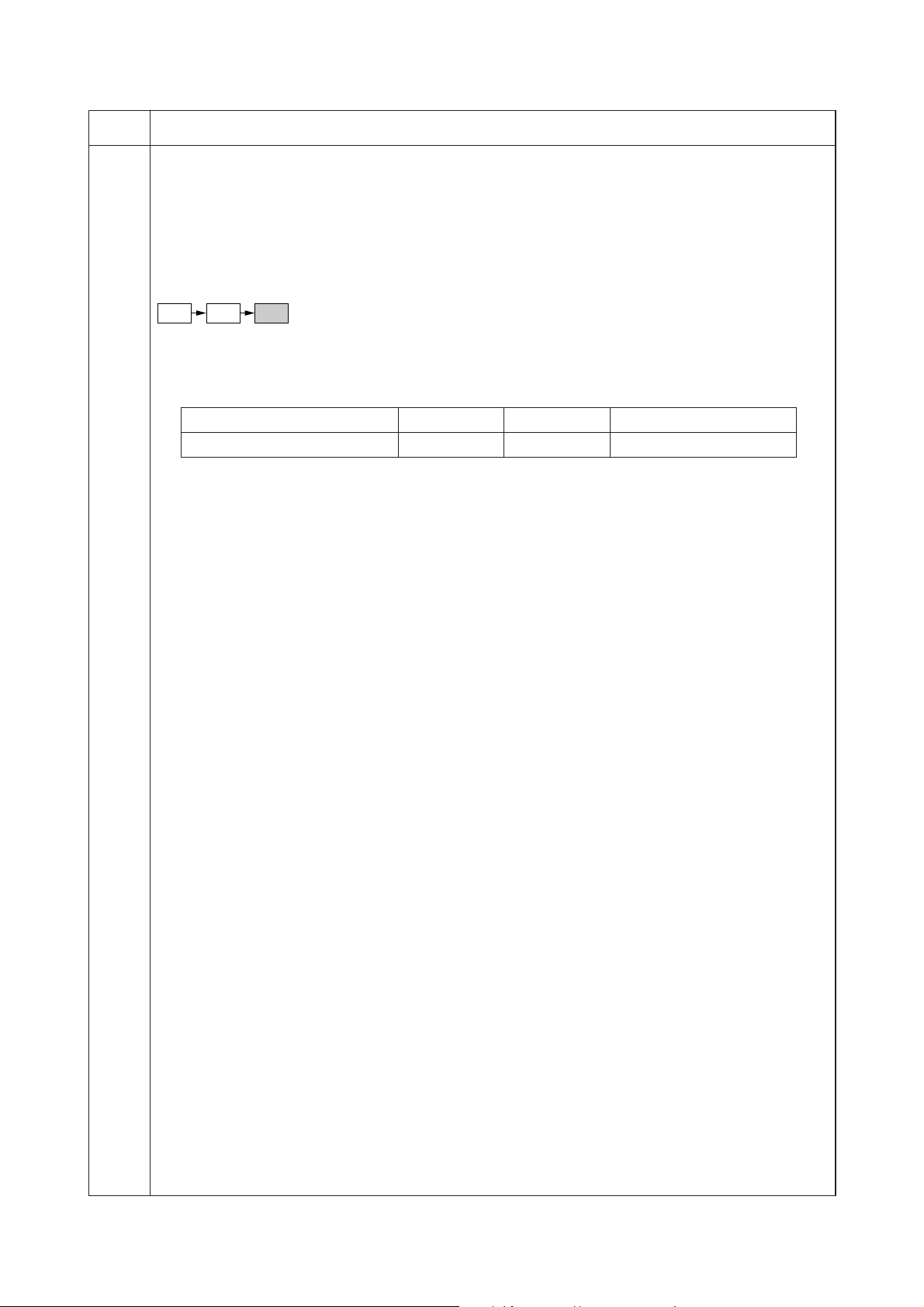
2BH/J
Maintenance
item No.
U070 Adjusting the DF magnification
Description
Adjusts the DF original scanning speed.
Purpose
To be executed if the correct magnification is not obtained in the auxiliary scanning direction when the optional
DF is used.
Caution
Before making this adjustment, ensure that the following adjustments have been made in maintenance mode.
U053 U065 U070
Method
Press the start key. The screen for executing is displayed.
Setting
1. Change the setting using the cursor up/down keys.
Description Setting range Initial setting Change in value per step
Original conveying motor speed –25 to +25 0 0.1%
Increasing the setting makes the image longer, and decreasing it makes the image shorter.
2. Press the start key. The value is set.
Interrupt copy mode
While this maintenance item is being performed, copying from an original can be made in interrupt copy mode.
Completion
Press the stop/clear key at the screen for selecting an item. The screen for selecting a maintenance item No. is
displayed.
Description
1-4-15
Page 92

2BH/J
Maintenance
item No.
U071 Adjusting the DF scanning timing
Description
Adjusts the DF original scanning timing.
Purpose
To be executed if there is a regular error between the leading or trailing edges of the original and the copy
image when the optional DF is used.
Caution
Before making this adjustment, ensure that the following adjustments have been made in maintenance mode.
U034 U066 U071
Method
Press the start key. The screen for selecting an item is displayed.
Setting
1. Select the item to be set. The selected item is displayed in reverse.
2. Change the setting using the cursor up/down keys.
Display Description Setting range Initial setting
LEAD EDGE ADJ DF leading edge registration –32 to +32 0 0.17 mm
TRAIL EDGE ADJ DF trailing edge registration –32 to +32 0 0.17 mm
Increasing the setting moves the copy image backward, and decreasing it moves the copy image forward.
3. Press the start key. The value is set.
Interrupt copy mode
While this maintenance item is being performed, copying from an original can be made in interrupt copy mode.
Adjustment
1. In interrupt copy mode, make a copy using the DF.
2. Check the copy image and adjust the registration as follows.
For copy example 1, increase the setting of LEAD EDGE ADJ.
For copy example 2, decrease the setting of LEAD EDGE ADJ.
Description
Change in
value per step
1-4-16
Original Copy
example 1
Copy
example 2
Figure 1-4-2
Completion
Press the stop/clear key at the screen for selecting an item. The screen for selecting a maintenance item No. is
displayed.
Page 93
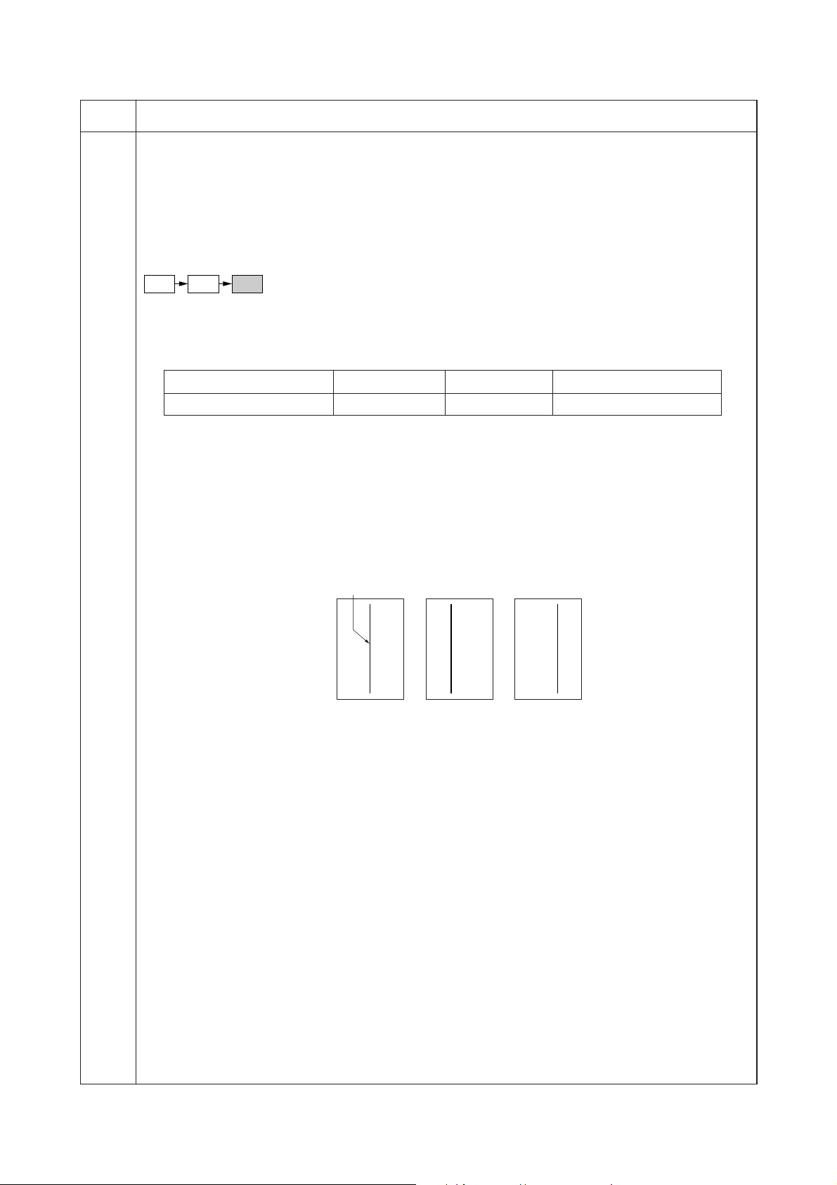
2BH/J
Maintenance
item No.
U072 Adjusting the DF center line
Description
Adjusts the scanning start position for the DF original.
Purpose
To be executed if there is a regular error between the centers of the original and the copy image when the
optional DF is used.
Caution
Before making this adjustment, ensure that the following adjustments have been made in maintenance mode.
U034 U067 U072
Method
Press the start key. The screen for executing is displayed.
Setting
1. Change the setting using the cursor up/down keys.
Description Setting range Initial setting Change in value per step
DF center line –39 to +39 0 0.17 mm
Increasing the setting moves the image to the right, and decreasing it moves the image to the left.
2. Press the start key. The value is set.
Interrupt copy mode
While this maintenance item is being performed, copying from an original can be made in interrupt copy mode.
Adjustment
1. In interrupt copy mode, make a copy using the DF.
2. Check the copy image and adjust the center line as follows.
For copy example 1, increase the setting.
For copy example 2, decrease the setting.
Description
Reference
Original Copy
example 1
Copy
example 2
Figure 1-4-3
Completion
Press the stop/clear key at the screen for selecting an item. The screen for selecting a maintenance item No. is
displayed.
1-4-17
Page 94

2BH/J
Maintenance
item No.
U073 Checking scanner operation
Description
Simulates the scanner operation under arbitrary conditions.
Purpose
To check scanner operation.
Method
1. Press the start key. The screen for selecting an item is displayed.
2. Select the item to be changed. The selected item is displayed in reverse.
3. Change the setting using the cursor up/down keys.
Display Operating conditions Setting range
ZOOM Magnification 100 to 400%
SIZE Original size See below.
LAMP On and off of the exposure lamp 0 (off) or 1 (on)
Original sizes for each setting in SIZE
Setting Paper size Setting Paper size
8 A4 42 A5R
9 B5 47 Folio
24 11" × 8
36 A3 53 11" × 15"
39 B4 55 8
40 A4R 56 8
41 B5R 58 5
4. Press the strat key. The setting is set.
5. Press the interrupt key. The copy mode screen is displayed.
6. Press the start key. Scanning starts under the selected conditions.
7. To stop operation, press the stop/clear key.
Completion
Press the stop/clear key when scanning stops. The screen for selecting a maintenance item No. is displayed.
U074 Adjusting the DF input light luminosity
Description
Adjusts the luminosity of the exposure lamp for scanning originals from the optional DF.
Purpose
Used if the exposure amount differs significantly between when scanning an original on the contact glass and
when scanning an original from the DF.
Method
Press the start key. The screen for executing is displayed.
Setting
1. Change the setting using the cursor up/down keys.
Description Setting range Initial setting
DF input light luminosity 0 to 8 1
Increasing the setting makes the luminosity higher, and decreasing it makes the luminosity lower.
2. Press the start key. The value is set.
Interrupt copy mode
While this maintenance item is being performed, copying from an original can be made in interrupt copy mode.
Completion
Press the stop/clear key at the screen for selecting an item. The screen for selecting a maintenance item No. is
displayed.
Description
1
/2" 52 11" × 17"
1
/2" × 14"
1
/2" × 11"
1
/2" × 81/2"
1-4-18
Page 95

2BH/J
Maintenance
item No.
U087 Turning the DF scanning position adjust mode on/off
Description
Turns on or off the DF scanning position adjust mode, in which the DF original scanning position is adjusted
automatically by determining the presence or absence of dust on the slit glass. Also changes the reference
data for identifying dust.
Reference
In the DF original scanning position adjust mode, the presence or absence of dust is determined by comparing
the scan data of the original trailing edge and that taken after the original is conveyed past the DF original
scanning position. If dust is identified, the DF original scanning position is adjusted for the following originals.
Purpose
Used to prevent appearance of black lines due to dust adhering in the original scanning position on the slit
glass when the DF is used.
Method
1. Press the start key. The screen for selecting an item is displayed.
2. Select the item to be set and press the start key.
Display Description
ON/OFF Setting the mode on/off
DATA Setting the reference data for identifying dust
Setting the mode on/off
1. Select ON or OFF. The selected item is displayed in reverse.
Display Description
ON DF scanning position adjust mode on
OFF DF scanning position adjust mode off
Initial setting: ON
2. Press the start key. The setting is set. The screen for selecting an item is displayed.
Setting the reference data for identifying dust
Available only when the mode is turned on.
1.Change the setting using the cursor up/down keys.
Description Setting range Initial setting
Minimum density to be regarded as dust 10 to 95 35
Example
The figure indicates the density in 256 levels of gray (0: white, 255: black). When the setting is 35, data of
the level of 35 or higher is regarded as dust and data of lower level is regarded as the background (scan
data taken when there is no original).
2. Press the start key. The value is set.
3. To return to the screen for selecting an item, press the stop/clear key.
Completion
Press the stop/clear key at the screen for selecting an item. The screen for selecting a maintenance item No. is
displayed.
Description
1-4-19
Page 96

2BH/J-1
Maintenance
item No.
U088 Setting the input filter (moiré reduction mode)
Description
Turns moiré reduction mode on and off by switching the input filter on and off.
Purpose
Used to prevent regular density unevenness (moiré) on halftone image areas of the copy image in text mode
and text and photo mode. Such moiré is more likely to appear when an enlargement or reduction copy is made
in text mode from an original containing large halftone image areas.
Method
Press the start key. The screen for selecting an item is displayed.
Setting
1. Select ON or OFF. The selected item is displayed in reverse.
Display Description
ON Moiré reduction mode
OFF Normal copy mode
Initial setting: OFF
If moiré on the copy image is significant, change the setting to ON. Note that when the moiré reduction
mode is turned on, the resolution may be slightly reduced.
2. Press the start key. The value is set. The screen for selecting a maintenance item No. is displayed.
Completion
To exit this maintenance item without changing the current setting, press the stop/clear key. The screen for
selecting a maintenance item No. is displayed.
U089 Outputting a MIP-PG pattern
Description
Selects and outputs the MIP-PG pattern created in the copier.
Purpose
When performing respective image printing adjustments, used to check the machine status apart from that of
the scanner with a non-scanned output MIP-PG pattern.
Method
1. Press the start key.
2. Select the MIP-PG pattern to be output.
Display Description Adjusting range
GRAYSCALE Gray scale –
MONO-LEVEL Mono level 0 to 255
256-LEVEL 256 level –
1dot-LINE 1 dot level –
3. Press the interrupt key to set the pattern output mode.
4. Press the start key. A MIP-PG pattern is output.
Completion
Press the stop/clear key.
The screen for selecting a maintenance item No. is displayed.
Description
1-4-20
Page 97

2BH/J
Maintenance
item No.
U091 Checking shading
Description
Performs scanning under the same conditions as before and after shading is performed, displaying the original
scanning values at nine points of the contact glass.
Purpose
To check the change in original scanning values before and after shading. The results may be used to decide
the causes for fixing unevenness (uneven density) of the gray area of an image: either due to optical (shading
or CCD) or other problems.
Also to check the causes for a white or black line appearing longitudinally.
Method
1. Press the start key. The screen for selecting an item is displayed.
2. Select the item to be operated. The selected item is displayed in reverse.
Display Description
SHD BEFORE Performs scanning before shading and displays the result.
SHD AFTER Performs scanning after shading and displays the result.
3. Press the start key. Scanning is performed under the selected conditions and the result is displayed.
When scanning is performed before shading, the scan value at the machine center should be slightly
different from those at the machine front and rear. When scanning is performed after shading, there should
be no difference between respective values. Any differences between the values at machine front and rear
indicates that scanner problem causes the fixing unevenness.
If the displayed results indicate no shading problems, the fixing unevenness (uneven copy density) is
caused by factors other than in the scanner section (shading or CCD).
If a black line appears, the cause may assumed to be based on the results of the scanning operation before
shading: if a white line appears, they may be assumed based on the results of the scanning operation after
shading. Note that depending on the thickness and location of the black or white line, it may not be possible
to use this method to determine the cause. This is because the displayed values obtained from scanning at
the limit of nine points are insufficient to provide significant information.
Description
20 mm from the machine left
200 mm from the machine left
400 mm from the machine left
100 mm from the
machine center
toward machine
front
Machine center
100 mm from the
machine center
toward machine
rear
Figure 1-4-4
4. To return to the screen for selecting an item, press the stop/clear key.
Completion
Press the stop/clear key at the screen for selecting an item. The screen for entering a maintenance item is
displayed.
1-4-21
Page 98

2BH/J
Maintenance
item No.
U092 Adjusting the scanner automatically
Description
Makes auto scanner adjustments in the order below using the specified original.
• Adjusting the scanner center line (U067)
• Adjusting the scanner leading edge registration (U066)
• Adjusting scanner magnification in the auxiliary direction (U065)
When this maintenance item is performed, the settings in U065, U066 and U067 are also changed.
Purpose
Used to make respective auto adjustments for the scanner.
Method
1. Place the specified original (P/N: 2A068020) on the contact glass.
2. Press the start key. The screen for executing is displayed.
3. Press the start key. Auto adjustment starts. When adjustment is complete, each adjusted value is
displayed.
Display Description
SCAN CENTER Scanner center line
SCAN TIMING Scanner leading edge registration
SUB SCAN Scanner magnification in the auxiliary scanning direction
If a problem occurs during auto adjustment, DATA: XX (XX is replaced by an error code) is displayed and
operation stops. Should this happen, determine the details of the problem and either repeat the procedure
from the beginning, or adjust the remaining items manually by running the corresponding maintenance
items.
Completion
Press the stop/clear key after auto adjustment is complete. The screen for selecting a maintenance item No. is
displayed.
If the stop/clear key is pressed during auto adjustment, adjustment stops and no settings are changed.
Description
1-4-22
Page 99

2BH/J-1
Maintenance
item No.
U093 Setting the exposure density gradient
Description
Changes the exposure density gradient in manual density mode, depending on respective image modes (text,
text and photo, photo, text in fax mode, photo in fax mode).
Purpose
To set how the image density is altered by a change of one step in the manual density adjustment. Also used to
make copy image darker or lighter.
Start
1. Press the start key. The screen for selecting an item is displayed.
2. Select the image mode to be adjusted and press the start key. The screen for the selected item is
displayed.
Display Description
MIXED Density in text and photo mode
TEXT Density in text mode
PHOTO Density in photo mode
FAX TEXT Density in the text in fax mode
FAX PHOTO Density in the photo in fax mode
Setting
1. Select the item to be adjusted. The selected item is displayed in reverse.
Display Description
DARKER Change in density when manual density is set dark
LIGHTER Change in density when manual density is set light
2. Adjust the setting using the cursor up/down keys.
Display Setting range Initial setting
MIXED DARKER/MIXED LIGHTER 0 to 3/0 to 3 0/0
TEXT DARKER/TEXT LIGHTER 0 to 3/0 to 3 0/0
PHOTO DARKER/PHOTO LIGHTER 0 to 3/0 to 3 0/0
FAX TEXT DARKER/FAX TEXT LIGHTER 0 to 4/0 to 9 2/2
FAX PHOTO DARKER/FAX PHOTO LIGHTER 0 to 6/0 to 6 3/3
Increasing the setting makes the change in density larger, and decreasing it makes the change smaller.
Description
Image density
Dark
Light
Light
Setting: 3
Set to LIGHTER
Set to DARKER
Center
Setting: 0
Density adjustment
Dark
Figure 1-4-5 Exposure density gradient
3. Press the start key. The value is set.
4. To return to the screen for selecting an item, press the stop/clear key.
Interrupt copy mode
While this maintenance item is being performed, copying from an original can be made in interrupt copy mode.
Completion
Press the stop/clear key at the screen for selecting an item. The screen for selecting a maintenance item No. is
displayed.
1-4-23
Page 100

2BH/J
Maintenance
item No.
U099 Checking and setting the original size detection sensor
Description
Checks the operation of the original size detection sensor and sets the sensing threshold value.
Purpose
To adjust the sensitiveness of the sensor and size judgement time if the original size detection sensor
malfunctions frequently due to incident light or the like.
Start
1. Press the start key. The screen for selecting an item is displayed.
2. Select an item and press the start key. The screen for executing each item is displayed.
Display Description
DATA Displaying detection sensor transmission data
B/W LEVEL Setting detection sensor threshold value
Setting original size judgment time
Method to display the data for the sensor
1. Press the start key. The detection sensor transmission data is displayed.
Rear of machine
Center of machine
Front of machine
Description
: 123 123 123
: 123 123 123
: 255 255 255
Figure 1-4-6
2. To return to the screen for selecting an item, press the stop/clear key.
Setting
1. Select an item to be set.
Display Description Setting range Initial setting
LEVEL Detection sensor threshold value 0 to 255 170
WAIT TIME Original size judgment time* 0 to 100 50
ORIG. AREA Original size detection position display (mm) 0 to 350 –
SIZE Detected original size display 0 to 63 –
* Time from activation of the original detection switch (ODSW) to original size judgment
Method to set the detection threshold value
1. Adjust the preset value using the cursor up/down keys.
* A larger value increases the sensor sensitivity, and a smaller value decreases it.
2. Press the start key. The value is set.
3. To return to the screen for selecting an item, press the stop/clear key.
Method to set the original size judgment time
1. Adjust the preset value using the cursor up/down keys.
* A larger value increases the original size judgment time, and a smaller value decreases it.
2. Press the start key. The value is set.
3. To return to the screen for selecting an item, press the stop/clear key.
Completion
Press the stop/clear key at the screen for selecting an item. The screen for maintenance item No. is displayed.
1-4-24
 Loading...