

Page 1

KM-1620
SERVICE
MANUAL
Published in Sep. ’03
842C9111
Revision 1
Page 2

CAUTION
Danger of explosion if battery is incorrectly replaced. Replace only with the same or equivalent
type recommended by the manufacturer. Dispose of used batteries according to the
manufacturer’s instructions.
CAUTION
Double-pole/neutral fusing.
Page 3

Safety precautions
This booklet provides safety warnings and precautions for our service personnel to ensure the safety of
their customers, their machines as well as themselves during maintenance activities. Service personnel
are advised to read this booklet carefully to familiarize themselves with the warnings and precautions
described here before engaging in maintenance activities.
Page 4

Safety warnings and precautions
Various symbols are used to protect our service personnel and customers from physical danger and
to prevent damage to their property. These symbols are described below:
DANGER: High risk of serious bodily injury or death may result from insufficient attention to or incorrect
compliance with warning messages using this symbol.
WARNING:Serious bodily injury or death may result from insufficient attention to or incorrect compliance
with warning messages using this symbol.
CAUTION:Bodily injury or damage to property may result from insufficient attention to or incorrect
compliance with warning messages using this symbol.
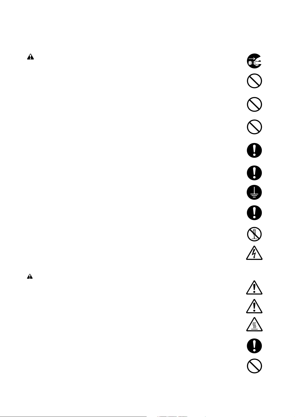
Symbols
The triangle ( ) symbol indicates a warning including danger and caution. The specific point
of attention is shown inside the symbol.
General warning.
Warning of risk of electric shock.
Warning of high temperature.
indicates a prohibited action. The specific prohibition is shown inside the symbol.
General prohibited action.
Disassembly prohibited.
indicates that action is required. The specific action required is shown inside the symbol.
General action required.
Remove the power plug from the wall outlet.
Always ground the copier.
Page 5

1. Installation Precautions
WARNING
• Do not use a power supply with a voltage other than that specified. Avoid multiple connections to
one outlet: they may cause fire or electric shock. When using an extension cable, always check
that it is adequate for the rated current. ............................................................................................
• Connect the ground wire to a suitable grounding point. Not grounding the copier may cause fire or
electric shock. Connecting the earth wire to an object not approved for the purpose may cause
explosion or electric shock. Never connect the ground cable to any of the following: gas pipes,
lightning rods, ground cables for telephone lines and water pipes or faucets not approved by the
proper authorities. .............................................................................................................................
CAUTION:
• Do not place the copier on an infirm or angled surface: the copier may tip over, causing injury. .....
• Do not install the copier in a humid or dusty place. This may cause fire or electric shock. ..............
• Do not install the copier near a radiator, heater, other heat source or near flammable material.
This may cause fire. ..........................................................................................................................
• Allow sufficient space around the copier to allow the ventilation grills to keep the machine as cool
as possible. Insufficient ventilation may cause heat buildup and poor copying performance. ..........
• Always handle the machine by the correct locations when moving it. ..............................................
• Always use anti-toppling and locking devices on copiers so equipped. Failure to do this may
cause the copier to move unexpectedly or topple, leading to injury..................................................
• Avoid inhaling toner or developer excessively. Protect the eyes. If toner or developer is
accidentally ingested, drink a lot of water to dilute it in the stomach and obtain medical attention
immediately. If it gets into the eyes, rinse immediately with copious amounts of water and obtain
medical attention. ..............................................................................................................................
• Advice customers that they must always follow the safety warnings and precautions in the copier’s
instruction handbook. ........................................................................................................................
Page 6
2. Precautions for Maintenance
WARNING
• Always remove the power plug from the wall outlet before starting machine disassembly...............
• Always follow the procedures for maintenance described in the service manual and other related
brochures. .........................................................................................................................................
• Under no circumstances attempt to bypass or disable safety features including safety
mechanisms and protective circuits. .................................................................................................
• Always use parts having the correct specifications...........................................................................
• Always use the thermostat or thermal fuse specified in the service manual or other related
brochure when replacing them. Using a piece of wire, for example, could lead to fire or other
serious accident. ...............................................................................................................................
• When the service manual or other serious brochure specifies a distance or gap for installation of a
part, always use the correct scale and measure carefully. ...............................................................
• Always check that the copier is correctly connected to an outlet with a ground connection. ............
• Check that the power cable covering is free of damage. Check that the power plug is dust-free. If
it is dirty, clean it to remove the risk of fire or electric shock. ............................................................
• Never attempt to disassemble the optical unit in machines using lasers. Leaking laser light may
damage eyesight. ..............................................................................................................................
• Handle the charger sections with care. They are charged to high potentials and may cause
electric shock if handled improperly. .................................................................................................
CAUTION
• Wear safe clothing. If wearing loose clothing or accessories such as ties, make sure they are
safely secured so they will not be caught in rotating sections...........................................................
• Use utmost caution when working on a powered machine. Keep away from chains and belts. .......
• Handle the fixing section with care to avoid burns as it can be extremely hot. .................................
• Check that the fixing unit thermistor, heat and press rollers are clean. Dirt on them can cause
abnormally high temperatures...........................................................................................................
• Do not remove the ozone filter, if any, from the copier except for routine replacement....................
Page 7

• Do not pull on the AC power cord or connector wires on high-voltage components when removing
them; always hold the plug itself. ......................................................................................................
• Do not route the power cable where it may be stood on or trapped. If necessary, protect it with a
cable cover or other appropriate item. ..............................................................................................
• Treat the ends of the wire carefully when installing a new charger wire to avoid electric leaks........
• Remove toner completely from electronic components. ...................................................................
• Run wire harnesses carefully so that wires will not be trapped or damaged. ...................................
• After maintenance, always check that all the parts, screws, connectors and wires that were
removed, have been refitted correctly. Special attention should be paid to any forgotten
connector, trapped wire and missing screws. ..................................................................................
• Check that all the caution labels that should be present on the machine according to the
instruction handbook are clean and not peeling. Replace with new ones if necessary. ...................
• Handle greases and solvents with care by following the instructions below: ....................................
· Use only a small amount of solvent at a time, being careful not to spill. Wipe spills off completely.
· Ventilate the room well while using grease or solvents.
· Allow applied solvents to evaporate completely before refitting the covers or turning the main
switch on.
· Always wash hands afterwards.
• Never dispose of toner or toner bottles in fire. Toner may cause sparks when exposed directly to
fire in a furnace, etc...........................................................................................................................
• Should smoke be seen coming from the copier, remove the power plug from the wall outlet
immediately. ......................................................................................................................................
3. Miscellaneous
WARNING
• Never attempt to heat the drum or expose it to any organic solvents such as alcohol, other than
the specified refiner; it may generate toxic gas. ................................................................................
Page 8

CONTENTS
1-1 Specifications
1-1-1 Specifications ....................................................................................................................................... 1-1-1
1-1-2 Parts names and their functions ........................................................................................................... 1-1-3
(1) Copier ............................................................................................................................................. 1-1-3
(2) Operation panel .............................................................................................................................. 1-1-4
1-1-3 Machine cross section .......................................................................................................................... 1-1-5
1-1-4 Drive system ........................................................................................................................................ 1-1-6
1-2 Handling Precautions
1-2-1 Drum .................................................................................................................................................... 1-2-1
1-2-2 Toner .................................................................................................................................................... 1-2-1
1-2-3 Installation environment ....................................................................................................................... 1-2-2
1-3 Installation
1-3-1 Unpacking and installation ................................................................................................................... 1-3-1
(1) Installation procedure ..................................................................................................................... 1-3-1
1-3-2 Setting initial copy modes .................................................................................................................... 1-3-5
1-3-3 Installing the paper feeder (option) ...................................................................................................... 1-3-6
1-3-4 Installing the DP (option) ...................................................................................................................... 1-3-8
1-3-5 Installing the duplex unit (option) ....................................................................................................... 1-3-11
1-3-6 Installing the drawer heater (option) ................................................................................................... 1-3-14
1-3-7 Installing the key counter (option) ...................................................................................................... 1-3-17
2C9-1
1-4 Maintenance Mode
1-4-1 Maintenance mode ............................................................................................................................... 1-4-1
(1) Executing a maintenance item ....................................................................................................... 1-4-1
(2) Maintenance mode item list ............................................................................................................ 1-4-2
(3) Contents of maintenance mode items ............................................................................................ 1-4-5
1-4-2 Copier management ........................................................................................................................... 1-4-45
(1) Using the copier management mode ............................................................................................ 1-4-45
(2) Setting department management items ........................................................................................ 1-4-46
(3) Copy default ................................................................................................................................. 1-4-46
1-5 Troubleshooting
1-5-1 Paper misfeed detection ...................................................................................................................... 1-5-1
(1) Paper misfeed indication ................................................................................................................ 1-5-1
(2) Paper misfeed detection conditions ................................................................................................ 1-5-2
(3) Paper misfeeds ............................................................................................................................... 1-5-6
1-5-2 Self-diagnosis ..................................................................................................................................... 1-5-15
(1) Self-diagnostic function ................................................................................................................ 1-5-15
(2) Self-diagnostic codes ................................................................................................................... 1-5-15
1-5-3 Image formation problems ................................................................................................................. 1-5-20
(1) No image appears (entirely white). ............................................................................................... 1-5-21
(2) No image appears (entirely black). ............................................................................................... 1-5-21
(3) Image is too light. ......................................................................................................................... 1-5-22
(4) Background is visible. ................................................................................................................... 1-5-22
(5) A white line appears longitudinally. .............................................................................................. 1-5-22
(6) A black line appears longitudinally. .............................................................................................. 1-5-23
(7) A black line appears laterally. ....................................................................................................... 1-5-23
(8) One side of the copy image is darker than the other. ................................................................... 1-5-23
(9) Black dots appear on the image. .................................................................................................. 1-5-24
(10) Image is blurred. ........................................................................................................................... 1-5-24
(11) The leading edge of the image is consistently misaligned with the original. ................................ 1-5-24
(12) The leading edge of the image is sporadically misaligned with the original. ................................ 1-5-25
(13) Paper creases. ............................................................................................................................. 1-5-25
1-1-1
Page 9

2C9
(14) Offset occurs. ............................................................................................................................... 1-5-25
(15) Image is partly missing. ................................................................................................................ 1-5-26
(16) Fixing is poor. ............................................................................................................................... 1-5-26
(17) Image is out of focus. ................................................................................................................... 1-5-26
(18) Image center does not align with the original center. ................................................................... 1-5-27
1-5-4 Electrical problems ............................................................................................................................. 1-5-28
(1) The machine does not operate when the power switch is turned on. ........................................... 1-5-28
(2) The drive motor does not operate (C200). ................................................................................... 1-5-28
(3) The registration motor does not operate. ..................................................................................... 1-5-28
(4) The exit motor does not operate. .................................................................................................. 1-5-28
(5) The scanner motor does not operate. .......................................................................................... 1-5-29
(6) Cooling fan motor 1 does not operate. ......................................................................................... 1-5-29
(7) Cooling fan motor 2 does not operate. ......................................................................................... 1-5-29
(8) The paper feed clutch does not operate. ...................................................................................... 1-5-29
(9) The bypass paper feed clutch does not operate. ......................................................................... 1-5-29
(10) The cleaning lamp does not turn on. ............................................................................................ 1-5-29
(11) The exposure lamp does not turn on. ........................................................................................... 1-5-29
(12) The exposure lamp does not turn off. ........................................................................................... 1-5-30
(13) The fixing heater does not turn on (C600). ................................................................................... 1-5-30
(14) The fixing heater does not turn off. ............................................................................................... 1-5-30
(15) Main charging is not performed. ................................................................................................... 1-5-30
(16) Transfer charging is not performed. ............................................................................................. 1-5-30
(17) No developing bias is output. ....................................................................................................... 1-5-30
(18) The original size is not detected. .................................................................................................. 1-5-30
(19) The original size is not detected correctly. ................................................................................... 1-5-30
(20) The message requesting paper to be loaded is shown when paper is present in the drawer. ..... 1-5-31
(21) The size of paper in the drawer is not displayed correctly. ........................................................... 1-5-31
(22) A paper jam in the paper feed, paper conveying or fixing section is indicated when
the power switch is turned on. ...................................................................................................... 1-5-31
(23) The message requesting covers to be closed is displayed when the front cover and
left cover are closed. .................................................................................................................... 1-5-31
(24) Others. .......................................................................................................................................... 1-5-31
1-5-5 Mechanical problems ......................................................................................................................... 1-5-32
(1) No primary paper feed. ................................................................................................................. 1-5-32
(2) No secondary paper feed. ............................................................................................................ 1-5-32
(3) Skewed paper feed. ...................................................................................................................... 1-5-32
(4) The scanner does not travel. ........................................................................................................ 1-5-32
(5) Multiple sheets of paper are fed at one time.................................................................................. 1-5-32
(6) Paper jams. .................................................................................................................................. 1-5-32
(7) Toner drops on the paper conveying path. ................................................................................... 1-5-32
(8) Abnormal noise is heard. .............................................................................................................. 1-5-32
1-6 Assembly and Disassembly
1-6-1 Precautions for assembly and disassembly ......................................................................................... 1-6-1
(1) Precautions ..................................................................................................................................... 1-6-1
(2) Running a maintenance item .......................................................................................................... 1-6-2
1-6-2 Paper feed section ............................................................................................................................... 1-6-3
(1) Detaching and refitting the separation pulley ................................................................................. 1-6-3
(2) Detaching and refitting the forwarding pulley and paper feed pulley .............................................. 1-6-5
(3) Detaching and refitting the paper conveying unit ........................................................................... 1-6-7
(4) Detaching and refitting the bypass paper feed pulley and bypass separation pad ........................ 1-6-9
(5) Detaching and refitting the registration left roller .......................................................................... 1-6-11
(6) Detaching and refitting the registration cleaner ............................................................................ 1-6-11
(7) Adjustment after roller and clutch replacement ............................................................................ 1-6-12
(7-1) Adjusting the leading edge registration of image printing .................................................... 1-6-12
(7-2) Adjusting the leading edge registration for memory image printing ..................................... 1-6-13
(7-3) Adjusting the center line of image printing ........................................................................... 1-6-14
(7-4) Adjusting the margins for printing ........................................................................................ 1-6-15
(7-5) Adjusting the amount of slack in the paper .......................................................................... 1-6-16
1-1-2
Page 10

2C9
1-6-3 Optical section .................................................................................................................................... 1-6-17
(1) Detaching and refitting the exposure lamp ................................................................................... 1-6-17
(2) Detaching and refitting the scanner wires .................................................................................... 1-6-18
(2-1) Detaching the scanner wires ............................................................................................... 1-6-18
(2-2) Fitting the scanner wires ...................................................................................................... 1-6-20
(3) Detaching and refitting the ISU (reference) .................................................................................. 1-6-23
(4) Detaching and refitting the laser scanner unit .............................................................................. 1-6-24
(5) Adjusting the longitudinal squareness (reference) ....................................................................... 1-6-27
(6) Adjusting magnification of the scanner in the main scanning direction ........................................ 1-6-28
(7) Adjusting magnification of the scanner in the auxiliary scanning direction ................................... 1-6-29
(8) Adjusting the scanner leading edge registration ........................................................................... 1-6-30
(9) Adjusting the scanner center line ................................................................................................. 1-6-31
(10) Adjusting the margins for scanning an original on the contact glass ............................................ 1-6-32
1-6-4 Drum section ....................................................................................................................................... 1-6-33
(1) Detaching and refitting the drum unit ............................................................................................ 1-6-33
(2) Detaching and refitting the drum separation claws ....................................................................... 1-6-34
(3) Detaching and refitting the main charger unit ............................................................................... 1-6-35
1-6-5 Developing section .............................................................................................................................. 1-6-36
(1) Detaching and refitting the developing unit .................................................................................. 1-6-36
1-6-6 Transfer section .................................................................................................................................. 1-6-37
(1) Detaching and refitting the transfer roller ..................................................................................... 1-6-37
1-6-7 Fixing section ...................................................................................................................................... 1-6-38
(1) Detaching and refitting the fixing unit ........................................................................................... 1-6-38
(2) Detaching and refitting the press roller ......................................................................................... 1-6-39
(3) Detaching and refitting the fixing heater M and S ......................................................................... 1-6-40
(4) Detaching and refitting the heat roller separation claws ............................................................... 1-6-41
(5) Detaching and refitting the heat roller ........................................................................................... 1-6-42
(6) Detaching and refitting the fixing thermostat ................................................................................ 1-6-43
(7) Detaching and refitting the fixing thermistor ................................................................................. 1-6-43
1-7 Requirements on PCB Replacement
1-7-1 Upgrading the firmware on the main PCB ............................................................................................ 1-7-1
1-7-2 Adjustment-free variable resisters (VR) ............................................................................................... 1-7-2
1-7-3 Remarks on engine PCB or main PCB replacement............................................................................ 1-7-2
2-1 Mechanical construction
2-1-1 Paper feed section ............................................................................................................................... 2-1-1
2-1-2 Optical section ...................................................................................................................................... 2-1-4
(1) Original scanning ............................................................................................................................ 2-1-5
(2) Image printing ................................................................................................................................. 2-1-6
2-1-3 Drum section ........................................................................................................................................ 2-1-8
2-1-4 Developing section ............................................................................................................................. 2-1-10
(1) Formation of magnetic brush ........................................................................................................ 2-1-11
(2) Single component developing system .......................................................................................... 2-1-12
2-1-5 Transfer and separation sections ....................................................................................................... 2-1-13
2-1-6 Fixing section ..................................................................................................................................... 2-1-15
(1) Fixing temperature system ........................................................................................................... 2-1-16
(2) Fixing temperature control based on ambient temperature .......................................................... 2-1-16
2-1-7 Exit and switchback sections ............................................................................................................. 2-1-17
2-1-8 Duplex section .................................................................................................................................... 2-1-18
(1) Paper conveying operation in duplex copying .............................................................................. 2-1-19
1-1-3
2-2 Electrical Parts Layout
2-2-1 Electrical parts layout ........................................................................................................................... 2-2-1
(1) PCBs .............................................................................................................................................. 2-2-1
(2) Switches and sensors ..................................................................................................................... 2-2-2
(3) Motors ............................................................................................................................................. 2-2-3
(4) Other electrical components ........................................................................................................... 2-2-4
Page 11

2C9
2-3 Operation of the PCBs
2-3-1 Power source PCB ............................................................................................................................... 2-3-1
2-3-2 Main PCB ............................................................................................................................................. 2-3-4
2-3-3 Engine PCB .......................................................................................................................................... 2-3-8
2-3-4 Operation unit PCB ............................................................................................................................ 2-3-14
2-3-5 CCD PCB ........................................................................................................................................... 2-3-17
2-4 Appendixes
Timing chart No. 1 .......................................................................................................................................... 2-4-1
Timing chart No. 2 .......................................................................................................................................... 2-4-2
Timing chart No. 3 .......................................................................................................................................... 2-4-3
Timing chart No. 4 .......................................................................................................................................... 2-4-4
Chart of image adjustment procedures .......................................................................................................... 2-4-5
Maintenance parts list..................................................................................................................................... 2-4-8
Periodic maintenance procedures .................................................................................................................. 2-4-9
Optional devices supplied parts list .............................................................................................................. 2-4-11
General wiring diagram ................................................................................................................................ 2-4-12
1-1-4
Page 12

1-1-1 Specifications
Type ............................................... Desktop
Copying system.............................. Indirect electrostatic system
Originals ......................................... Sheets, books and 3-dimensional objects (Maximum original size: A3)
Maximum size: A3/11" × 17"
Original feed system ...................... Fixed
Copy paper..................................... Paper weights
Drawer: 64 – 105 g/m
Bypass table: 45 – 160 g/m
Paper type
Drawer: Plain paper, recycled paper and colored paper
Bypass table: Plain paper, recycled paper, thin paper, thick paper and colored paper
Copying sizes ................................. Maximum: A3/11" × 17"
Minimum: A6R /5
Magnification ratios ........................ Manual mode: 50 – 200%, 1% increments
Copy speed .................................... At 100% magnification in copy mode:
A4: 16 copies/min.
A4R: 13 copies/min.
A3: 8 copies/min.
A5R: 10 copies/min.
A6R: 10 copies/min.
B5: 16 copies/min.
B5R: 13 copies/min.
B4 (257 × 364 mm): 8 copies/min.
1
11" × 8
8
/2": 16 copies/min.
1
/2" × 11": 10 copies/min.
11" × 17": 8 copies/min.
81/2" × 14": 8 copies/min.
First copy time ................................ Approximately 5.9 s (A4/11" × 8
Warm-up time................................. Less then 19 s (room temperature 23°C/73.4°F, 50% RH)
Paper feed system ......................... Automatic feed
Capacity:
Drawers: 300 sheets (80 g/m2)
Manual feed
Capacity:
Bypass: 50 sheets (A4/11" × 8
25 sheets (A3, B4, 11" × 17", 8
Paper ejection system .................... In-machine ejection (face down)
Capacity: 250 sheets (80 g/m2)
Continuous copying........................ 1 – 250 sheets
Photoconductor .............................. OPC (drum diameter 30 mm)
Charging system ............................ Single positive corona charging
Recording system .......................... Semiconductor laser
Developing system ......................... Single component developing system
Toner: magnetism toner
Toner replenishing: automatic from a toner container
Transfer system ............................. Transfer roller
Separation system ......................... Curvature separation and separation electrode
Fixing system ................................. Heat roller
Heat source: halogen heaters (120 V specifications:main 550 W, sub 400W/ 220-240
V specifications:main 600 W, sub 450 W)
Control temperature: 170°C/338°F (180°C/356°F on and after 6th sheet)
Abnormally high temperature protection device: 180°C/356°F thermostat
Fixing pressure: 44.1 N
Charge erasing system .................. Exposure by cleaning lamp
Cleaning system............................. Cleaning blade
Scanning system ............................ Flat bed scanning by CCD image sensor
Bitmap memory .............................. 18 MB (standard)
Image storage memory .................. 14 MB (standard)
Resolution ...................................... 600 × 600 dpi
Light source.................................... Inert gas lamp
2
1
/2" × 81/2"
2
1
1
/2" or less)
/2")
1
/2" × 14")
2C9
1-1-1
Page 13

2C9
Dimensions .................................... 571 (W) × 552 (D) × 502 (H) mm
1
22
/2" (W) × 213/4" (D) × 193/4" (H)
Weight ............................................Approx. 39 kg/85.8 lbs
Floor requirements ......................... 885 (W) × 552 (D) mm
13
/16" (W) × 213/4" (D)
34
Functions........................................ Automatic paper selection, Image quality selection, Automatic sizeing selection
function, zoom function, Duplex copy, Divided copy, Binding margin, Border width,
Aggregate copy, Sort copy, Eco-copy, Copy program and Section management mode
Power source ................................. 120 V AC, 60 Hz, 11 A
220 – 240 V AC, 50 Hz, 4.5 A (Average)
Power consumption........................ 1320 W
Options ........................................... Document processer, paper feeder, duplex unit, key counter
• Duplex unit
Type ............................................... Internal type
Copy paper..................................... Paper weights: 60 – 90 g/m
2
Paper type: Plain paper, recycled paper and colored paper
1
Paper sizes .................................... A3 – A5R/11" × 17" – 5
/2" × 81/2"
Power source ................................. Electrically connected to the copier
Dimensions .................................... 368 (W) × 53 (D) × 180 (H) mm
1
/2" (W) × 21/16" (D) × 71/16" (H)
14
Weight ............................................Approx. 0.65 kg/1.43 lbs
1-1-2
Page 14

1-1-2 Parts names and their functions
(1) Copier
2C9
1 Original cover
2 Copy storage section
3 Operation panel
4 Drawer
5 Width guide
6 Length guide
7 Left cover handle
8 Bypass tray
9 Support guide
0 Slider
Figure 1-1-1
! Contact glass
@ Original size indicator plate
# Left cover
$ Waste toner box
% Toner container release lever
^ Toner container
& Cleaner rod
* Front cover
( Power switch
1-1-3
Page 15

2C9
(2) Operation panel
Metric
Inch
1 Start key (Indicator)
2 Stop/Clear key
3 Reset key
4 Numeric keys
5 Energy Saver key (Indicator)
6 Interrupt key (Indicator)
7 Management key
8 Auto Exposure key
9 Copy exposure adjustment keys (Indicators)
0 Eco-copy key
! Image mode selection key
@ Program key
# Copy quantity/magnification display
$ Zoom (+) key
% Zoom (-) key
^ Recall%/Enter key
& Magnification Select key
* Paper Select key
1-1-4
Figure 1-1-2
( Paper supply indicator
) Paper supply level indicator
⁄ Paper jam indicator
¤ Bypass tray indicator
‹ Original size Select key
› Toner recovery indicator
fi Toner supply indicator
fl Memory overflow indicator
‡ Maintenance indicator
° Auto Selection key
· Aggregate copy key
‚ Duplex copy key
ΠDivided key
„ Sort key
´ Border lightening key
‰ Margin key
ˇ Printer type selection key
Page 16

1-1-3 Machine cross section
2C9
Figure 1-1-3 Machine cross section
1 Paper feed section
2 Optical section
3 Drum section
4 Developing section
5 Transfer and separation section
6 Fixing section
7 Exit and switchback section
8 Duplex section
Light path
Paper path
1-1-5
Page 17

2C9
1-1-4 Drive system
1-1-6
1 Drive motor gear
2 Gear 122
3 Registration gear 51
4 Registration motor gear
5 Gear 32
6 Gear 25
7 Gear 25
8 Gear 20
9 Paper feed clutch gear
0 Gear 30
! Gear 31
@ Gear 25
# Gear 49
$ Gear 30/23
Figure 1-1-4
% Developing gear 25
^ Developing gear 26
& Fixing joint gear 29
* Gear 40
( Gear 40
) Gear 88/34
⁄ Gear 40
¤ Fixing joint gear 40
‹ Coupling gear
› Gear 50
fi Gear 60
fl Exit motor gear
‡ Gear 43/20
Page 18

1-2-1 Drum
Note the following when handling or storing the drum.
• When removing the drum unit, never expose the drum surface to strong direct light.
• Keep the drum at an ambient temperature between –20°C/–4°F and 55°C/131°F and at a relative humidity not higher
than 90% RH. Avoid abrupt changes in temperature and humidity.
• Avoid exposure to any substance which is harmful to or may affect the quality of the drum.
• Do not touch the drum surface with any object. Should it be touched by hands or stained with oil, clean it.
1-2-2 Toner
Store the toner in a cool, dark place. Avoid direct light and high humidity.
2C9
1-2-1
Page 19

2C9
1-2-3 Installation environment
1. Temperature: 10 - 32.5°C/50 - 90.5°F
2. Humidity: 15 - 80%RH
3. Power supply: 120 V AC, 11 A
4. Power source frequency: 50 Hz ±0.3%/60 Hz ±0.3%
5. Installation location
• Avoid direct sunlight or bright lighting. Ensure that the photoconductor will not be exposed to direct sunlight or other
strong light when removing paper jams.
• Avoid extremes of temperature and humidity, abrupt ambient temperature changes, and hot or cold air directed onto
the machine.
• Avoid dust and vibration.
• Choose a surface capable of supporting the weight of the machine.
• Place the machine on a level surface (maximum allowance inclination: 1° ).
• Avoid air-borne substances that may adversely affect the machine or degrade the photoconductor, such as
mercury, acidic of alkaline vapors, inorganic gasses, NOx, SOx gases and chlorine-based organic solvents.
• Select a room with good ventilation.
6. Allow sufficient access for proper operation and maintenance of the machine.
Machine front: 1000 mm/39
Machine right: 300 mm/11
220 - 240 V AC, 4.5 A (Average)
3
/8" Machine rear: 100 mm/315/16"
13
/16" Machine left: 300 mm/1113/16"
d
a
f
c
b
e
a: 571 mm/22
b: 552 mm/21
c: 502 mm/19
d: 1371.5 mm/54"
e: 1272 mm/501/16"
f: 952.5 mm/37
1
/2"
3
/4"
3
/4"
1
/2"
1-2-2
Figure 1-2-1 Installation dimensions
Page 20

1-3-1 Unpacking and installation
(1) Installation procedure
Start
Unpack.
Install the optional paper feeder.
2C9
Installing the toner
(maintenance item U130).
Remove the tapes and pins.
Install the original cover or the optional DP.
Install the optional duplex unit.
Install the toner container.
Connect the power cord.
Load paper.
Output an own-status report
(maintenance item U000).
Exit maintenance mode.
Make test copies.
Completion of the machine installation.
1-3-1
Page 21

2C9
Unpack.
1 Copier
2 Power cord
3 Toner container
4 Outer case
5 Lower left pad
6 Lower right pad
7 Upper left pad
8 Upper right pad
9 Inner frame
* Place the machine on a level surface.
1-3-2
Figure 1-3-1 Unpacking
0 Left spacer
! Rear spacer
@ Rear pad
# Skid
$ Belt
% Cartridge spacer
^ Machine cover
& Bar code labels
Page 22

Install the optional paper feeder.
1. Install the optional paper feeder as necessary
(see page 1-3-6 to 1-3-7).
Remove the tapes and pins.
1. Remove the eight tapes.
2C9
Tape
Tapes
Tape
Tape
Tapes
2. Remove the two pins for light source unit.
Install the original cover or the optional DP.
Figure 1-3-2
Pins
Figure 1-3-3
1. Install the original cover or optional DP (see page 1-3-8 to 1-3-10 when installing the DP).
Install the optional duplex unit.
1. Install the optional duplex unit as necessary (see pages 1-3-11 to 1-3-13).
1-3-3
Page 23

2C9
Install the toner container.
1. Open the front cover.
2. Tap the top of the toner container five to six
times.
3. Shake the toner container approximately 10 times
in the horizontal direction to stir toner.
4. Turn the toner container release lever and gently
push the toner container into the copier.
*Push the container all the way into the copier until
it locks in place.
5. Restore the toner container release lever.
6. Close the front cover.
Toner container release lever
Toner container
Figure 1-3-4
Connect the power cord.
1. Connect the power cord to the connector on the copier.
2. Insert the power plug into the wall outlet and turn the power switch on.
Installing the toner (maintenance item U130).
1. Enter the maintenance mode by entering “10871087” using the numeric keys.
2. Enter “130” using the numeric keys and press the start key.
3. Press the start key to execute the maintenance item.
Installation of toner starts and "9" is indicated in the copy quantity display. Each time one minute elapses, the
indicated value decrements. When the installation is complete, "Gd" will be displayed if the installation is
successful or "nG" will be displayed if it has failed.
4. Press the stop/clear key.
Load paper.
1. Load paper in the drawer.
Output an own-status report (maintenance item U000).
1. Enter “000” using the numeric keys and press the start key.
2. Select “d-L” and press the start key to output a list of the current settings of the maintenance items.
3. Press the stop/clear key.
Exit maintenance mode.
1. Enter "001" using the numeric keys and press the start key.
The machine exits the maintenance mode.
Make test copies.
1. Place an original and make test copies.
Completion of the machine installation.
1-3-4
Page 24

1-3-2 Setting initial copy modes
Factory settings are as follows:
2C9
Maintenance
item No.
U253
U254
U255
U258
U260
U342
Contents
Switching between double and single counts
Turning auto start function on/off
Setting auto clear time
Switching copy operation at toner
empty detection
Changing the copy count timing
Setting the ejection restriction
Factory setting
Double count
ON
90s
SINGLE MODE
After ejection
ON
1-3-5
Page 25

2C9
1-3-3 Installing the paper feeder (option)
<Procedure>
1. Place the copier on the paper feeder by aligning the
positioning insertion sections of the copier with the
positioning pins at the rear part of the paper feeder.
* When placing the copier, take care not to hit the
copier against the drawer, the pins or ground plate
of the paper feeder.
For stacking paper feeders for use:
Stack a paper feeder on another paper feeder by
aligning the positioning insertion sections of the first
paper feeder with the positioning pins at the rear
part of the second paper feeder. (Up to three paper
feeders can be stacked.)
Positioning pins
Paper feeder
Figure 1-3-5
Positioning
pins
2. If a type of paper that is not included in the
specifications for the standard sheet cassette size is
used, replace the cassette size sheet indication with
the supplied one.
3. Insert the copier power plug into the wall outlet and
turn the copier power switch on.
Load paper in the drawer and make test copies to
check the operation.
Positioning
pins
Figure 1-3-6
1-3-6
Cassette size
sheet indication
Figure 1-3-7
Page 26

Adjusting the leading edge timing
1. Run maintenance mode 034.
Press the image quality mode key until "Text" is lit. (group 1)
First paper feeder: Press the exposure key until "exp3" is lit. (mode 3)
Second paper feeder: Press the exposure key until "exp4" is lit. (mode 4)
Third paper feeder: Press the exposure key until "exp5" is lit. (mode 5)
Make a test copy to check the image. If an adequate image cannot be obtained, carry out the following adjustment.
2. If a copy example a is obtained, increase the adjustment value.
If a copy example b is obtained, decrease the adjustment value.
Setting range: -5.0 - 10.0
3. Make a test copy again.
4. Repeat steps 2 and 3 until an adequate image is obtained.
Adequate image Copy example a Copy example b
2C9
Figure 1-3-8
Adjusting the center line
1. Run maintenance mode 034.
Press the image quality mode key until "Text" and "Photo" are lit. (group 2)
First paper feeder: Press the exposure key until "exp3" is lit. (mode 3)
Second paper feeder: Press the exposure key until "exp4" is lit. (mode 4)
Third paper feeder: Press the exposure key until "exp5" is lit. (mode 5)
Make a test copy to check the image. If an adequate image cannot be obtained, carry out the following adjustment.
2. If a copy example a is obtained, increase the adjustment value.
If a copy example b is obtained, decrease the adjustment value.
Setting range: -8.0 - 10.0
3. Make a test copy again.
4. Repeat steps 2 and 3 until an adequate image is obtained.
Adequate image Copy example a Copy example b
Figure 1-3-9
1-3-7
Page 27

2C9
1-3-4 Installing the DP (option)
<Procedure>
1. Remove the original holder and remove the two
screws from the rear top cover.
2. Pass the two pins through the screw holes of the rear
top cover and attach them to the lower frame.
Pin
Screw
Pin
Screw
Figure 1-3-10
3. Place the DP on the copier by fitting the pins into the
holes at the hinge sections of the DP and sliding
them toward the front side.
4. Secure the DP with the two chrome TP screws M4 x
10 and the two screws that have been removed in
step 1.
Chrome
TP screw
M4 x 10
DP
Pin
Hole Hole
Pin
Figure 1-3-11
Chrome
TP screw
Screw
M4 x 10
Screw
1-3-8
DP
Figure 1-3-12
Page 28

5. Close the DP, fit the fixing fitting from the rear side of
15mm15mm
15mm
15mm
Lines
Lines
Center line
Original
the right hinge, and secure it with the two bronze TP
screws M3 x 06.
6. Connect the cable of the DP to the copier.
* Be sure to tighten the fixing screws on both side of
the connector.
7. Paste the caution label that corresponds to the
language according to the destination to the DP.
2C9
Cable
Fixing fitting
Bronze TP screws M3 x 06
Figure 1-3-13
[Operation check]
1. Prepare an original on which 4 lines are drawn 15
mm from the edges and the center line is drawn.
2. Set the original on the DP and make a test copy to
check the copy image.
At this time, set the paper guide for the original table
and drawer to the paper size to be used.
3. If the copy image does not match the original image,
carry out the following adjustments in maintenance
mode.
• Maintenance mode 070 (sub-scan line adjustment)
• Maintenance mode 071 (leading edge timing
adjustment)
• Maintenance mode 072 (center line adjustment)
Caution label
Figure 1-3-14
Figure 1-3-15
1-3-9
Page 29

2C9-1
Maintenance mode 070 (sub-scan line adjustment)
For copy example a: decrease the value.
For copy example b: increase the value.
Changing the value by one changes the sub-scan line by 0.1%.
The larger the value, the larger the magnification of the sub-scan line of the copy image.
The smaller the value, the smaller the magnification of the sub-scan line of the copy image.
Original Copy example a Copy example b
Figure 1-3-16
Maintenance mode 071 (leading edge timing adjustment)
For copy example a: increase the value.
For copy example b: decrease the value.
Changing the value by one moves the leading edge by 0.17 mm.
The larger the value, the later the image scan start timing.
The smaller the value, the earlier the image scan start timing.
Original Copy example a Copy example b
Maintenance mode 072 (center line adjustment)
For copy example a: increase the value.
For copy example b: decrease the value.
Changing the value by one moves the center line by 0.17 mm.
The larger the value, the center of the image moves toward the right.
The smaller the value, the center of the image moves toward the left.
Original Copy example a Copy example b
1-3-10
Figure 1-3-17
Figure 1-3-18
Page 30
1-3-5 Installing the duplex unit (option)
Left cover
Strap
Stop
ring
Fitting projection
Pin
Stopper
<Procedure>
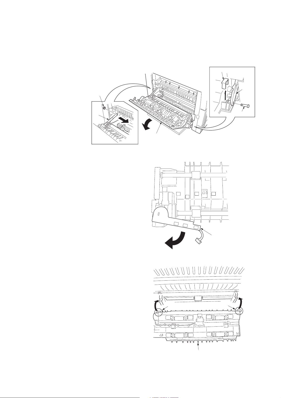
1. Open the left cover.
2. Remove the stop ring and the strap from the rear
side.
3. Restore the conveyor section.
4. Remove the fitting projection and pin, and then
remove the stopper from the front side.
5. Open the left cover until it is put horizontally.
6. Turn the wire guide section of the duplex unit in the
direction indicated by the arrow.
2C9
Figure 1-3-19
7. Insert the axis sections of the duplex unit into the Ushape grooves of the conveyer unit.
Figure 1-3-20
Axis section
Figure 1-3-21
Wire guide section
Axis section
Duplex unit
1-3-11
Page 31
2C9
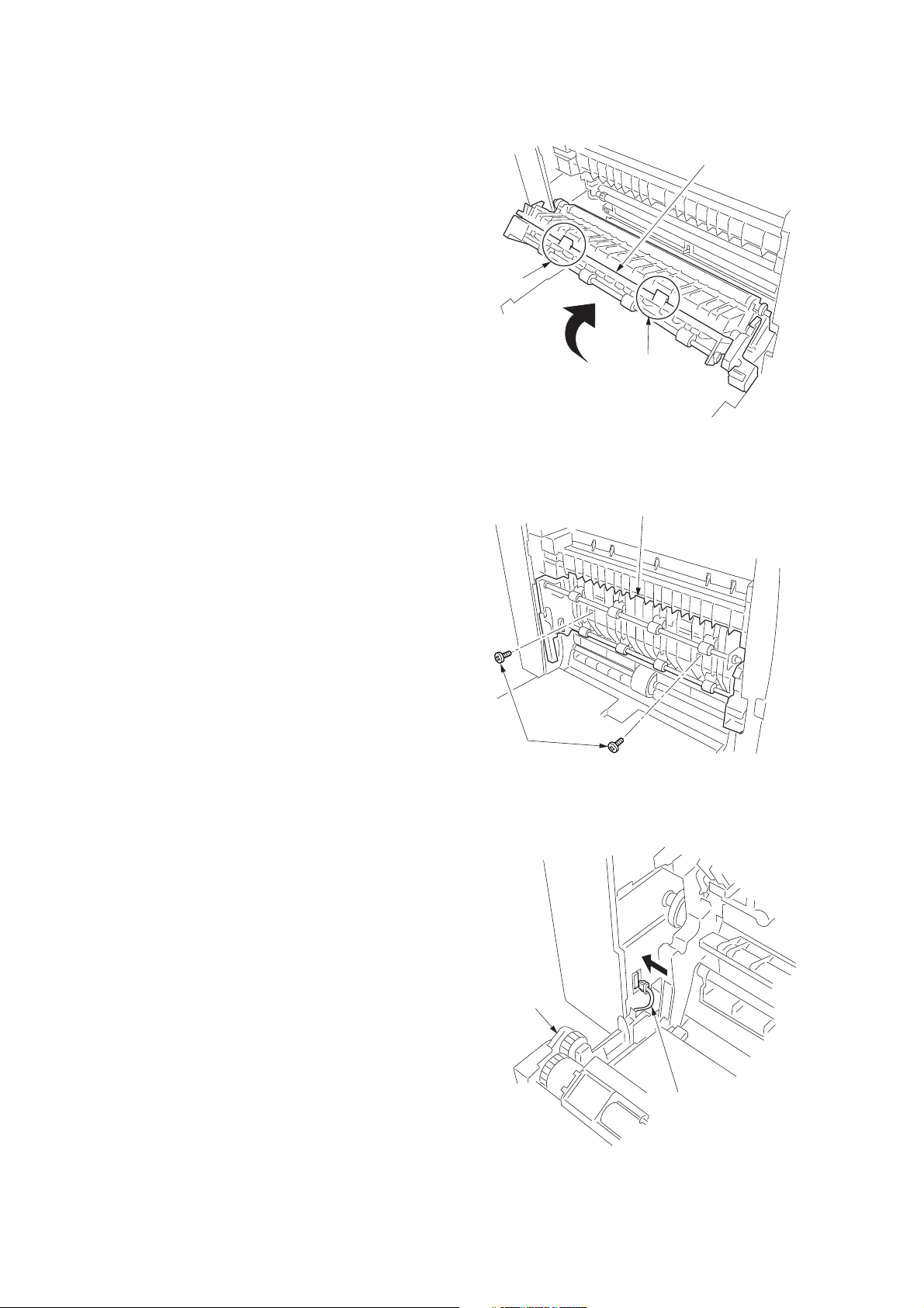
8. Press the duplex unit in the direction indicated by the
arrow to fit the claws into the conveyer unit.
Duplex unit
Claw
Claw
Figure 1-3-22
9. Secure the duplex unit with the two S tite screws M3
x 06.
10. Open the conveyer unit and connect the connector of
the duplex unit to the copier.
11. Reattach the removed parts to their original
positions.
12. Connect the copier power plug to the wall outlet and
turn the copier power switch on.
Duplex unit
S tite screws
M3 x 06
Figure 1-3-23
1-3-12
Duplex unit
Connector
Figure 1-3-24
Page 32

Adjusting the leading edge timing
1. Run maintenance mode 034.
Press the image quality mode key until "Text" is lit. (group 1)
Press the exposure key until "exp1" is flashing.
(mode 6)
Make a test copy in the duplex mode to check the image. If an adequate image cannot be obtained, carry out the
following adjustment.
2. If a copy example a is obtained, increase the adjustment value.
If a copy example b is obtained, decrease the adjustment value.
Setting range: -5.0 - 10.0
3. Make a test copy again.
4. Repeat steps 2 and 3 until an adequate image is obtained.
Adequate image Copy example a Copy example b
2C9-1
Figure 1-3-25
Adjusting the center line
1. Run maintenance mode 034.
Press the image quality mode key until "Text" and "Photo" are lit. (group 2)
Press the exposure key until "exp1" is flashing.
(mode 6)
Make a test copy in the duplex mode to check the image. If an adequate image cannot be obtained, carry out the
following adjustment.
2. If a copy example a is obtained, increase the adjustment value.
If a copy example b is obtained, decrease the adjustment value.
Setting range: -8.0 - 10.0
3. Make a test copy again.
4. Repeat steps 2 and 3 until an adequate image is obtained.
Adequate image Copy example a Copy example b
Figure 1-3-26
1-3-13
Page 33

2C9
1-3-6 Installing the drawer heater (option)
Drawer heater installation requires the following parts:
• Drawer heater (P/N 120 V specifications: 2C960030, 220-240 V specifications: 2C960040)
• One (1) M4 × 10 tap-tight S binding screw (P/N B3024100)
<Procedure>
1. Remove the right cover.
2. Pull out the drawer.
3. Remove the three screws and then the front right
cover.
Front right cover
Figure 1-3-27
1-3-14
Page 34

4. Insert the cassette heater from the bottom of the
Drawer heater
Screw hole
Projections
Hole in the right frame
Connector
M4 × 10 tap tight
S binding screw
Holes in the rear frame
machine and attach it to the copier.
1) Pass the connector of the cassette heater through
the hole located in the right frame of the machine to
pull it out.
2) Insert the projections at the rear side of the cassette
heater mounting plate into the two holes in the rear
frame of the machine.
3) Position the screw hole of the drawer heater to the
screw hole of the front frame of the machine and
secure the heater using the M4 × 10 Taptite S
binding screw.
2C9
Figure 1-3-28
1-3-15
Page 35

2C9
5. Remove the two screws and open the power source
PCB in the direction indicated by the arrow.
* Take care not to open the power source PCB too
much.
6. Fit the wire of the drawer heater into the groove of
the frame and put it inside the power source PCB.
* Fit the wire into the groove so that the band mounted
to the wire is located above the frame.
Wire of the drawer heater
Power source PCB
Band
7. Reattach the power source PCB to its original
position and connect the connector of the drawer
heater to YC8 of the power source PCB.
8. Refit all the removed parts.
Figure 1-3-29
Connector
YC8
Figure 1-3-30
1-3-16
Page 36

1-3-7 Installing the key counter (option)
Key counter installation requires the following parts:
• Key counter cover (P/N 2A360010)
• Key counter retainer (P/N 66060030)
• Key counter mount (P/N 66060040)
• Key counter assembly (P/N 41529210)
• Four (4) M4 × 6 bronze TP-A screws (P/N B4304060)
• One (1) M4 × 35 round head screw (P/N B0004350)
• Two (2) M3 × 6 bronze flat-head screws (P/N B2303060)
• One (1) M3 bronze nut (P/N C2303000)
• Key counter mounting plate (P/N 2C960100)
• Key counter wire (P/N 2C960110)
Procedure
1. Fit the key counter socket assembly to the key
counter retainer using the two screws and nut.
2. Fit the key counter mount to the key counter cover
using the two screws, and attach the key counter
retainer to the mount using the two screws.
2C9-1
M4 × 6 screws (B4304060)
Key counter retainer (66060030)
M3 nut
(C2303000)
M4 × 6 screws (B4304060)
Key counter socket assembly
(41529210)
M3 × 6 flat-head screws (B2303060)
Figure 1-3-31
Key counter mount (66060040)
Key counter cover
(2A360010)
1-3-17
Page 37

2C9-1
p
3. Remove the rear cover.
4. Cut out the aperture plate on the right cover using
nippers.
5. Connect the 4-pin connector of the key counter wire
(located at a longer distance from the tube) to YC13
on the engine PCB, pass the wire through the two
clamps, and pull the other 4-pin connector out from
the aperture of the right cover.
* Arrange the key counter wire behind the optical
system wire as shown in the illustration.
6. Fold the 7-pin connector of the key counter wire
back, pass the wire through the clamp at the upper
part of the controller box, and hang it.
Aperture
4-pin connector
7-pin connector
Clamp
7. Pass the connector of the key counter through the
aperture of the key counter mounting plate, and
engage the projection of key counter mounting plate
with the square hole of the key counter cover.
Aperture
Key counter wire
4-pin connector
Clamp
Figure 1-3-32
YC13
4-
in connector
Key counter mounting
plate (2C960100)
Key counter
cover
1-3-18
Projection
Square hole
Figure 1-3-33
Page 38

8. Connect the 4-pin connector of the key counter to the
key counter wire.
9. Engage the projection of the key counter mounting
plate with the aperture of the right cover.
10. Secure the key counter cover and the key counter
mounting plate together with the copier using a M4 x
35 screw.
11. Refit the rear cover.
Aperture
Key counter wire
4-pin connector
Key counter mounting
plate (2C960100)
2C9-1
Projection
Key counter
cover
M4×35 screw
(B0004350)
12. Insert the key counter into the key counter socket
assembly.
13. Turn the main switch on and enter the maintenance
mode.
14. Run maintenance item U204 and select “KEY-
COUNTER.”
15. Exit the maintenance mode.
16. Check that if the key counter is removed, “U1” is
displayed in the copy quantity display.
17. Check that the counter counts up as copies are
made.
Figure 1-3-34
1-3-19
Page 39

1-4-1 Maintenance mode
The copier is equipped with a maintenance function which can be used to maintain and service the machine.
(1) Executing a maintenance item
Start
2C9
Yes
Enter “10871087” using
the numeric keys.
Enter the maintenance item
number using the zoom
+/- keys or numeric keys.
Press the start key.
The selected maintenance item is run.
Press the stop/clear key.
Repeat the same
maintenance item?
Maintenance mode is entered.
The maintenance item is
selected.
Yes
No
Run another maintenance
item?
No
Enter “001” using the
+/- keys
or numeric keys
and press the start key.
End
zoom
Maintenance mode is exited.
1-4-1
Page 40
2C9
(2) Maintenance mode item list
Section
General
Initialization
Drive, paper
feed and paper
conveying
system
Optical
Item
No. setting*
U000 Outputting an own-status report —
U001 Exiting the maintenance mode —
U004 Checking the machine number —
U005 Copying without paper —
U019 Displaying the ROM version —
U020 Initializing all data —
U021 Initializing memories —
U030 Checking motor operation —
U031 Checking switches for paper conveying —
U032 Checking clutch operation —
U034 Setting paper timing
• Adjusting the leading edge registration 5.1/0/0/0/0/0
• Adjusting the center line -1.2/0/0/0/0/0
U035 Setting folio size
• Length 330
• Width 210
U051 Adjusting the amount of slack in the paper 20/0/70/80/80/0
U053 Performing fine adjustment of the motor speed
• Drive motor speed adjustment 0
• Polygon motor speed adjustment 0
• Exit motor speed adjustment 0
• Registration motor speed adjustment 0
• Motor speed adjustment (for paper feed from bypass tray) 0
• Motor speed adjustment (for paper feed from optional paper feeder) 0
• Motor speed adjustment (in duplex mode) 0
U060 Adjusting the scanner input properties 12
U061 Turning the exposure lamp on —
U063 Adjusting the shading position 0
U065 Adjusting the scanner magnification
• Main scanning direction 0
• auxiliary scanning direction –12
U066 Adjusting the leading edge registration for scanning an original on the 10
contact glass
U067 Adjusting the center line for scanning an original on the contact glass 0
U068 Adjusting the scanning position for originals from the DP 0
U070 Adjusting the DP magnification 0
U071 Adjusting the DP scanning timing
• Adjusting leading edge registration 0
• Adjusting trailing edge registration 0
U072 Adjusting the DP center line 0
U073 Checking scanner operation —
U074 Adjusting the DP input light luminosity 1
U087 Turning the DP scanning position adjust mode on/off 35
U088 Setting the input filter (moiré reduction mode) Off
U089 Outputting a MIP-PG pattern —
U091 Checking shading —
U092 Adjusting the scanner automatically —
U093 Setting the exposure density gradient
• Text/text and photo/photo mode 0/0/0
U099 Checking the original size detection —
Maintenance item contents
Initial
* Initial setting for executing maintenance item U020
1-4-2
Page 41

2C9
Section
High voltage
Developing
Fixing and
cleaning
Operation
panel and
support
equipment
Mode setting
Item
No. setting*
U100 Setting the main high voltage
• Grid control voltage 135
• Copy interval 60
• Copy quantity 50
• Correction amount 10
U101 Setting the other high voltages
• Developing bias clock frequency 27
• Developing bias clock duty 45
• Transfer control voltage (large size) 168
• Transfer control voltage (small size) 179
• Transfer charging output OFF timing 38
• Transfer charging output ON timing 34
• Separation control voltage 1
• Separation charging output ON timing 33
• Separation charging output OFF timing 43
U110 Checking/clearing the drum count —
U130 Toner install mode —
U144 Setting toner loading operation 0
U158 Checking/clearing the developing count —
U161 Setting the fixing control temperature
• Primary stabilization fixing temperature 140
• Secondary stabilization fixing temperature 160
• Copying operation temperature 1 170
• Copying operation temperature 2 180
• Number of sheets for fixing control 5
• Number of sheets for fixing control (thick paper) 20
U162 Stabilizing fixing forcibly —
U163 Resetting the fixing problem data —
U167 Checking/clearing the fixing count —
U199 Checking the fixing temperature —
U200 Turning all LEDs on —
U202 Setting the KMAS host monitoring system —
U203 Operating DP separately —
U204 Setting the presence or absence of a key card or key counter Off
U207 Checking the operation panel keys —
U243 Checking the operation of the DP motors and solenoids —
U244 Checking the DP switches —
U250 Setting the maintenance cycle 150000
U251 Checking/clearing the maintenance count 0
U252 Setting the destination Japan
U253 Switching between double and single counts A3
U254 Turning auto start function on/off On
U255 Setting auto clear time 90
U258 Switching copy operation at toner empty detection Single mode
U260 Changing the copy count timing After ejection
U265 Setting the destination specifications 0
U332 Setting the size conversion factor 1.0
U342 Setting the ejection restriction On
U345 Setting the value for maintenance due indication —
Maintenance item contents
Initial
* Initial setting for executing maintenance item U020
1-4-3
Page 42

2C9
Section
Image
processing
Others
Item
No. setting*
U402 Adjusting margins of image printing —
U403 Adjusting margins for scanning an original on the contact glass —
U404 Adjusting margins for scanning an original from the DP —
U407 Adjusting the leading edge registration for memory image printing —
U901 Checking/clearing copy counts by paper feed locations —
U903 Checking/clearing the paper jam counts —
U904 Checking/clearing the service call counts —
U905 Checking/clearing counts by the DP —
U908 Checking the total count —
U910 Clearing the black ratio data —
U911 Checking/clearing copy counts by paper size —
U927 Clearing accounting counter —
U928 Checking/clearing the machine life counts —
U990 Checking/clearing the time for the exposure lamp to light —
U991 Checking the scanner count —
U993 Outputting a VTC-PG pattern —
Maintenance item contents
Initial
1-4-4
Page 43

(3) Contents of maintenance mode items
2C9
Maintenance
item No.
U000 Outputting an own-status report
Description
Outputs lists of the current settings of the maintenance items, and paper jam and service call occurrences.
Purpose
To check the current setting of the maintenance items, or paper jam or service call occurrences.
Before initializing the backup RAM, output a list of the current settings of the maintenance items to reenter the
settings after initialization or replacement.
Method
1. Press the start key. A selection item appears.
2. Select the item to be output using the copy exposure adjustment keys.
Display Output list
d-L List of the current settings of the maintenance modes
J-L List of the paper jam occurrences
C-L List of the service call occurrences
3. Press the start key. The test copy mode is entered and a list is output.
1
When A4/11" × 8
/2" paper is available, a report of this size is output. If not, specify the paper feed location.
When output is complete, the selected item appears.
Completion
Press the stop/clear key while a selection item is displayed. The indication for selecting a maintenance item No.
appears.
U001 Exiting the maintenance mode
Description
Exits the maintenance mode and returns to the normal copy mode.
Purpose
To exit the maintenance mode.
Method
Press the start key. The normal copy mode is entered.
U004 Checking the machine number
Description
Displays the machine number.
Purpose
To check the machine number.
Method
1. Press the start key. The currently set machine number is displayed.
2. Change the indication of the copy quantity display by lighting a copy exposure indicator using the copy
exposure adjustment keys.
Copy exposure indicator Copy quantity display
Exp. 1 (lit) 1st digit of machine number
Exp. 2 (lit) 2nd digit of machine number
Exp. 3 (lit) 3rd digit of machine number
Exp. 4 (lit) 4th digit of machine number
Exp. 5 (lit) 5th digit of machine number
Exp. 1 (flashing) 6th digit of machine number
Exp. 2 (flashing) 7th digit of machine number
Exp. 3 (flashing) 8th digit of machine number
Exp. 4 (flashing) 9th digit of machine number
Exp. 5 (flashing) 10th digit of machine number
Description
Completion
Press the stop/clear key. The indication for selecting a maintenance item No. appears.
1-4-5
Page 44

2C9
Maintenance
item No.
U005 Copying without paper
Description
Simulates the copy operation without paper feed.
Purpose
To check the overall operation of the machine.
Method
1. Press the start key. A selection item appears.
2. Select the item to be operated using the copy exposure adjustment keys.
Display Operation
P Only the copier operates.
P-d Both the copier and DP operate.
3. Press the interrupt key.
4. Set the operation conditions required. Changes in the following settings can be made.
• Paper feed locations
• Magnifications
• Number of copies: continuous copying is performed when set to 250.
• Copy density
• Keys on the operation panel other than the energy saver (preheat) key
5. To control the paper feed pulley, remove all the paper in the drawers, or the drawers. With the paper
present, the paper feed pulley does not operate.
6. Press the start key. The operation starts.
Copy operation is simulated without paper under the set conditions. When operation is complete, the
selected item appears.
7. To stop continuous operation, press the stop/reset key.
Completion
Press the stop/clear key while a selection item is displayed. The indication for selecting a maintenance item No.
appears.
U019 Displaying the ROM version
Description
Displays the part number of the ROM fitted to each board.
Purpose
To check the part number or to decide if the ROM version is new from the last digit of the number.
Method
1. Press the start key. A selection item appears.
2. Select the item to be displayed using the image mode selection key and copy exposure adjustment keys.
Image mode LEDs
Description
Copy exposure
indicator
Copy quantity display
1-4-6
Exp. 1 number of the main ROM
Exp. 2 number of the main ROM sub
Exp. 1 number of the engine ROM
Exp. 2 number of the engine ROM sub
Exp. 1 number of the first paper feeder ROM
Exp. 2 number of the second paper feeder ROM
Exp. 3 number of the third paper feeder ROM
Exp. 1 number of the DP ROM
: Off, : On, : Flashing
Completion
Press the stop/clear key. The indication for selecting a maintenance item No. appears.
Page 45

2C9
Maintenance
item No.
U020 Initializing all data
Description
Initializes all the backup RAM on the main board to return to the original settings.
Purpose
Run as needed.
Method
1. Press the start key.
2. Select “on” using the zoom +/– keys.
Display Operation
––– Canceling initialization
on Executing initialization
3. Press the start key. All data in the backup RAM is initialized, and the original settings for Japan specifications are set.
When initialization is complete, the machine automatically returns to the same status as when the main
switch is turned on.
Completion
To exit this maintenance item without executing initialization, press the stop/clear key. The indication for
selecting a maintenance item No. appears.
U021 Initializing memories
Description
Initializes the setting data other than that for adjustments due to variations between respective machines, i.e.,
settings for counters, service call history and mode settings. As a result, initializes the backup RAM according
to the specifications depending on the destination selected in U252.
Purpose
Used to return the machine settings to the factory settings.
Method
1. Press the start key.
2. Select “on” using the zoom +/– keys.
Display Operation
––– Canceling initialization
on Executing initialization
3. Press the start key. All data other than that for adjustments due to variations between machines is
initialized based on the destination setting. When initialization is complete, the machine automatically
returns to the same status as when the main switch is turned on.
Completion
To exit this maintenance item without executing initialization, press the stop/clear key. The indication for
selecting a maintenance item No. appears.
Description
1-4-7
Page 46
2C9
Maintenance
item No.
U030 Checking motor operation
Description
Drives each motor.
Purpose
To check the operation of each motor.
Method
1. Press the start key. A selection item appears.
2. Select the motor to be operated using the copy exposure adjustment keys.
Display Motor
A Drive motor (DM)
2F Registration motor (RM)
F1 Drawer drive motor 1 (DDM1)*
F2 Drawer drive motor 2 (DDM2)*
F3 Drawer drive motor 3 (DDM3)*
EJ1 Exit motor (EM) forward rotation
EJ2 Exit motor (EM) reverse rotation
*: Optional
3. Press the start key. The selected motor operates.
4. To stop operation, press the stop/reset key.
Completion
Press the stop/clear key after operation stops. The indication for selecting a maintenance item No. appears.
U031 Checking switches for paper conveying
Description
Displays the on-off status of each paper detection switch on the paper path.
Purpose
To check if the switches for paper conveying operate correctly.
Method
1. Press the start key.
2. Turn each switche on and off manually to check the status. When the on-status of a switch is detected, the
original size indicator corresponding to the operated switch lights.
Original size indicator Switch
A3R/Ledger Exit switch (ESW)
A5R/Legal Registration switch (RSW)
A4/Letter-R Drawer feed switch 1 (DFSW1)*
B4R/Letter Drawer feed switch 2 (DFSW2)*
B5R/Statement Feedshift switch (FSSW)
Folio/U Duplex paper conveying switch (DUPPCSW)*
*: Optional
Completion
Press the stop/clear key. The indication for selecting a maintenance item No. appears.
Description
1-4-8
Page 47
2C9
Maintenance
item No.
U032 Checking clutch operation
Description
Turns each clutch on.
Purpose
To check the operation of each clutch.
Method
1. Press the start key. A selection item appears.
2. Select the clutch to be operated using the copy exposure adjustment keys.
3. Press the start key. The selected clutch turns on for 1 s.
Display Clutch
P1 Paper feed clutch (PFCL)
Pb Bypass paper feed clutch (BYPPFCL)
F1 Drawer paper feed clutch 1 (DPFCL1)*
F2 Drawer paper feed clutch 2 (DPFCL2)*
F3 Drawer paper feed clutch 3 (DPFCL3)*
*: Optional
Completion
Press the stop/clear key. The indication for selecting a maintenance item No. appears.
U034 Adjusting the print start timing
Adjustment
See pages 1-6-12 and 14.
U035 Setting folio size
Description
Changes the image area for copying onto folio size paper.
Purpose
To prevent the image at the trailing edge, or right or left side of the paper from not being copied by setting the
actual size of the folio paper used.
Method
Press the start key.
Setting
1. Select the item to be set using the copy exposure adjustment keys.
2. Change the setting using the zoom +/– keys.
Copy exposure indicator Setting Setting range Initial setting
Exp. 1 Length 330 to 356 mm 330
Exp. 2 Width 200 to 220 mm 210
3. Press the start key. The value is set.
Completion
Press the stop/clear key. The screen for selecting a maintenance item No. is displayed.
U051 Adjusting the amount of slack in the paper
Adjustment
See page 1-6-16.
Description
1-4-9
Page 48

2C9
Maintenance
item No.
U053 Performing fine adjustment of the motor speed
Description
Performs fine adjustment of the speeds of the motors.
Purpose
Used to adjust the speed of the respective motors when the magnification is not correct. Also speed adjustment
for each paper source can be performed in group 2.
Method
Press the start key.
Setting
1. Select the group to be set or checked by lighting image mode LEDs using the image mode selection key.
2. Select the item by lighting a copy exposure indicator using the copy exposure adjustment keys.
3. Change the setting using the zoom +/– keys.
Image mode LED
Drive motor speed adjustment (unit: %)
Increasing the setting makes the image longer in the auxiliary scanning direction, and decreasing it makes
the image shorter in the auxiliary scanning direction.
Polygon motor speed adjustment (unit: %)
Increasing the setting makes the image longer in the main scanning direction and shorter in the auxiliary
scanning direction; decreasing the setting makes the image shorter in the main scanning direction and
longer in the auxiliary scanning direction.
4. Press the start key. The value is set.
Interrupt copy mode
While this maintenance item is being performed, a VTC pattern shown below is output in interrupt copy mode.
Correct values for an A3/11" × 17" output are:
A = 300 ± 1.5 mm
B = 270 ± 1.35 mm
Copy exposure
indicator range setting
Exp. 1 Drive motor speed adjustment –5.0 to +5.0 0
Exp. 2 Polygon motor speed adjustment –5.0 to +5.0 0
Exp. 3 Exit motor speed adjustment –5.0 to +5.0 0
Exp. 4 Registration motor speed adjustment –5.0 to +5.0 0
Exp. 1 Motor speed adjustment (for paper –5.0 to +5.0 0
Exp. 2 Motor speed adjustment (for paper –5.0 to +5.0 0
Exp. 3 Motor speed adjustment –5.0 to +5.0 0
Description
feed from bypass tray)
feed from optional paper feeder)
(in duplex mode)
Description
Setting Initial
1-4-10
Figure 1-4-1
Adjustment
1. Output an A3/11" × 17" VTC pattern in interrupt mode.
2. Measure A and B on the VTC pattern (Figure 1-4-1), and perform the following adjustments if they are
different from the correct sizes:
A: Drive motor speed adjustment
B: Polygon motor speed adjustment
Completion
Press the stop/clear key while a selection item is displayed. The indication for selecting a maintenance item No.
appears.
Page 49

2C9
Maintenance
item No.
U060 Adjusting the scanner input properties
Description
Adjusts the image scanning density.
Purpose
Used when the entire image appears too dark or light.
Method
Press the start key.
Setting
1. Change the setting using the zoom +/– keys.
Description Setting range Initial setting
Image scanning density 0 to 23 12
Increasing the setting makes the density lower, and decreasing it makes the density higher.
2. Press the start key. The value is set.
Test copy mode
While this maintenance item is being performed, copying from an original can be made in test copy mode.
Completion
Press the stop/clear key. The indication for selecting a maintenance item No. appears.
Caution
The following settings are also reset to the initial values by performing this maintenance item:
• Exposure density gradient set in maintenance mode (U093)
• Exposure set in the copy default item of the copier management mode
U061 Turning the exposure lamp on
Description
Turns the exposure lamp on.
Purpose
To check the exposure lamp.
Method
1. Press the start key. “on” appears.
2. Press the start key. The exposure lamp lights.
3. To turn the exposure lamp off, press the stop/clear key.
Completion
Press the stop/clear key. The indication for selecting a maintenance item No. appears.
Description
1-4-11
Page 50

2C9
Maintenance
item No.
U063 Adjusting the shading position
Description
Changes the shading position.
Purpose
Used when white lines continue to appear longitudinally on the image after the shading plate is cleaned. This is
due to flaws or stains inside the shading plate. To prevent this problem, the shading position should be changed
so that shading is possible without being affected by the flaws or stains.
Method
1. Press the start key.
2. Change the setting using the zoom +/– keys.
Description Setting range Initial setting Change in value per step
Shading position –5 to +5 0 0.17 mm
Increasing the setting moves the shading position toward the machine left, and decreasing it moves the
position toward the machine right.
3. Press the start key. The value is set.
Test copy mode
While this maintenance item is being performed, copying from an original can be made in test copy mode.
Completion
Press the stop/clear key. The indication for selecting a maintenance item No. appears.
U065 Adjusting the scanner magnification
Adjustment
See pages 1-6-28 and 29.
U066 Adjusting the leading edge registration for scanning an original on the contact glass
Adjustment
See page 1-6-30.
U067 Adjusting the center line for scanning an original on the contact glass
Adjustment
See page 1-6-31.
U068 Adjusting the scanning position for originals from the DP
Description
Adjusts the position for scanning originals from the DP.
Purpose
Used when there is a regular error between the leading edges of the original and the copy image when the DP
is used.
Method
Press the start key.
Setting
1. Change the setting using the zoom +/– keys.
Description Setting range Initial setting Change in value per step
Scanning position –17 to +17 0 0.254 mm
Increasing the setting moves the image backward, and decreasing it moves the image forward.
2. Press the start key. The value is set.
Completion
Press the stop/clear key. The indication for selecting a maintenance item No. appears.
Description
1-4-12
Page 51

2C9
Maintenance
item No.
U070 Adjusting the DP magnification
Description
Adjusts the DP original scanning speed.
Purpose
To be executed if the correct magnification is not obtained in the auxiliary scanning direction when the optional
DP is used.
Caution
Before making this adjustment, ensure that the following adjustments have been made in maintenance mode.
U053 U065 U070
Method
Press the start key.
Setting
1. Change the setting using the zoom +/– keys.
Description Setting range Initial setting Change in value per step
Original conveying motor speed –25 to +25 0 0.1%
Increasing the setting makes the image longer, and decreasing it makes the image shorter.
2. Press the start key. The value is set.
Interrupt copy mode
While this maintenance item is being performed, copying from an original can be made in interrupt copy mode.
Completion
Press the stop/clear key. The indication for selecting a maintenance item No. appears.
Description
1-4-13
Page 52

2C9
Maintenance
item No.
U071 Adjusting the DP scanning timing
Description
Adjusts the DP original scanning timing.
Purpose
To be executed if there is a regular error between the leading or trailing edges of the original and the copy
image when the optional DP is used.
Caution
Before making this adjustment, ensure that the following adjustments have been made in maintenance mode.
U034 U066 U071
Method
Press the start key.
Setting
1. Select the item by lighting a copy exposure indicator using the copy exposure adjustment keys.
2. Change the setting using the zoom +/– keys.
Copy exposure
indicator value per step
Description Setting range Initial setting
Exp. 1 DP leading edge registration –32 to +32 0 0.254 mm
Exp. 2 DP trailing edge registration –42 to +32 0 0.254 mm
Decreasing the setting moves the copy image backward, and increasing it moves the copy image forward.
3. Press the start key. The value is set.
Interrupt copy mode
While this maintenance item is being performed, copying from an original can be made in interrupt copy mode.
Adjustment
1. In interrupt copy mode, make a copy using the DP.
2. Check the copy image and adjust the registration as follows.
For copy example 1, decrease the setting of exp.1.
For copy example 2, increase the setting of exp.1.
Description
Change in
1-4-14
Original Copy
example 1
Copy
example 2
Figure 1-4-2
Completion
Press the stop/clear key while a selection item is displayed. The indication for selecting a maintenance item No.
appears.
Page 53

2C9-1
Maintenance
item No.
U072 Adjusting the DP center line
Description
Adjusts the scanning start position for the DP original.
Purpose
To be executed if there is a regular error between the centers of the original and the copy image when the
optional DP is used.
Caution
Before making this adjustment, ensure that the following adjustments have been made in maintenance mode.
U034 U067 U072
Method
Press the start key.
Setting
1. Change the setting using the zoom +/– keys.
Description Setting range Initial setting Change in value per step
DP center line –6.6 to +6.6 0.0 0.1 mm
Increasing the setting moves the image to the right, and decreasing it moves the image to the left.
2. Press the start key. The value is set.
Interrupt copy mode
While this maintenance item is being performed, copying from an original can be made in interrupt copy mode.
Adjustment
1. In interrupt copy mode, make a copy using the DP.
2. Check the copy image and adjust the center line as follows.
For copy example 1, increase the setting.
For copy example 2, decrease the setting.
Description
Reference
Original Copy
example 1
Copy
example 2
Figure 1-4-3
Completion
Press the stop/clear key. The indication for selecting a maintenance item No. appears.
1-4-15
Page 54

2C9
Maintenance
item No.
U073 Checking scanner operation
Description
Simulates the scanner operation under arbitrary conditions.
Purpose
To check scanner operation.
Method
1. Press the start key.
2. Select the item to be changed by lighting a copy exposure indicator using the copy exposure adjustment
keys.
3. Change the setting using the zoom +/– keys.
Copy exposure indicator Operating conditions Setting range
Exp. 1 Magnification 50 to 200%
Exp. 2 Paper size See below.
Exp. 3 On and off of the exposure lamp on or off
Paper size for each setting
Setting Paper size Setting Paper size
8 A4 42 A5R
9 B5 47 Folio
24 11" × 8
36 A3 53 11" × 15"
39 B4 55 81/2" × 14"
40 A4R 56 8
41 B5R 58 5
4. Press the interrupt key.
5. Press the start key. Scanning starts under the selected conditions.
6. To stop operation, press the stop/clear key.
Completion
Press the stop/clear key when scanning stops. The indication for selecting a maintenance item No. appears.
U074 Adjusting the DP input light luminosity
Description
Adjusts the luminosity of the exposure lamp for scanning originals from the DP.
Purpose
Used if the exposure amount differs significantly between when scanning an original on the contact glass and
when scanning an original from the DP.
Method
Press the start key.
Setting
1. Change the setting using the zoom +/– keys.
Description Setting range Initial setting
DP input light luminosity 0 to 8 1
Increasing the setting makes the luminosity higher, and decreasing it makes the luminosity lower.
2. Press the start key. The value is set.
Test copy mode
While this maintenance item is being performed, copying from an original can be made in test copy mode.
Completion
Press the stop/clear key. The indication for selecting a maintenance item No. appears.
Description
1
/2" 52 11" × 17"
1
/2" × 11"
1
/2" × 81/2"
1-4-16
Page 55
2C9
Maintenance
item No.
U087 Turning the DP scanning position adjust mode on/off
Description
Turns on or off the DP scanning position adjust mode, in which the DP original scanning position is adjusted
automatically by determining the presence or absence of dust on the slit glass. Also changes the reference
data for identifying dust.
Reference
In the DP original scanning position adjust mode, the presence or absence of dust is determined by comparing
the scan data of the original trailing edge and that taken after the original is conveyed past the DP original
scanning position. If dust is identified, the DP original scanning position is adjusted for the following originals.
Purpose
Used to prevent appearance of black lines due to dust adhering in the original scanning position on the slit
glass when the DP is used.
Method
1. Press the start key.
2. Select the item to be set by lighting a copy exposure indicator using the copy exposure adjustment keys.
Copy exposure indicator Description
Exp. 1 Setting the mode on/off
Exp. 2 Setting the reference data for identifying dust
Setting the mode on/off
1. Select “on” or “oFF” using the zoom +/– keys.
Display Description
on DP scanning position adjust mode on
oFF DP scanning position adjust mode off
Initial setting: on
2. Press the start key. The setting is set.
Setting the reference data for identifying dust
Available only when the mode is turned on.
1. Change the setting using the zoom +/– keys.
Description Setting range Initial setting
Minimum density to be regarded as dust 10 to 95 35
Example
The figure indicates the density in 256 levels of gray (0: white, 255: black). When the setting is 35, data of
the level of 35 or higher is regarded as dust and data of lower level is regarded as the background (scan
data taken when there is no original).
Description
2. Press the start key. The value is set.
Completion
Press the stop/clear key while a selection item is displayed. The indication for selecting a maintenance item No.
appears.
1-4-17
Page 56
2C9
Maintenance
item No.
U088 Setting the input filter (moiré reduction mode)
Description
Turns moiré reduction mode on and off by switching the input filter on and off.
Purpose
Used to prevent regular density unevenness (moiré) on halftone image areas of the copy image in text mode
and text and photo mode. Such moiré is more likely to appear when an enlargement or reduction copy is made
in text mode from an original containing large halftone image areas.
Method
Press the start key.
Setting
1. Select “on” or “oFF” using the zoom +/– keys.
Display Description
on Moiré reduction mode
oFF Normal copy mode
Initial setting: oFF
If moiré on the copy image is significant, change the setting to “on”. Note that when the moiré reduction
mode is turned on, the resolution may be slightly reduced.
2. Press the start key. The value is set. The indication for selecting a maintenance item No. appears.
Completion
To exit this maintenance item without changing the current setting, press the stop/clear key. The indication for
selecting a maintenance item No. appears.
U089 Outputting a MIP-PG pattern
Description
Selects and outputs a MIP-PG pattern created in the copier.
Purpose
When performing respective image printing adjustments, used to check the machine status apart from that of
the scanner with a non-scanned output MIP-PG pattern.
Method
1. Press the start key.
2. Select the MIP-PG pattern to be output using the copy exposure adjustment keys.
Display Setting Setting range Initial setting
G-S Gray scale - 0 Mono level 0 to 255 0
FFL 256 level - 1-d 1-dot level - -
3. Press the interrupt key. The machine enters the PG pattern output mode.
4. Press the start key. A MIP-PG pattern is output.
Completion
Press the stop/clear key. The indication for selecting a maintenance item No. appears.
Description
1-4-18
Page 57

2C9
Maintenance
item No.
U091 Checking shading
Description
Performs scanning under the same conditions as before and after shading is performed, displaying the original
scanning values at nine points of the contact glass.
Purpose
To check the change in original scanning values before and after shading. The results may be used to decide
the causes for fixing unevenness (uneven density) of the gray area of an image: either due to optical (shading
or CCD) or other problems.
Also to check the causes for a white or black line appearing longitudinally.
Method
1. Press the start key. A selection item appears.
2. Select the item to be operated using the zoom +/– keys.
Display Operation
on Performs scanning before shading and displays the result.
oFF Performs scanning after shading and displays the result.
3. Press the start key. Scanning is performed under the selected conditions and the result is displayed.
4. Change the measurement point by lighting a copy exposure indicator or making one flash using the copy
exposure adjustment keys. For the correspondence between the measurement points and the copy
exposure indicators, see Figure 1-4-4.
100 mm from the machine
center toward machine rear
Machine center
100 mm from the machine
center toward machine front
Description
123
456
789
20 mm from the machine left
Point Copy exposure indicator
1 exp. 1 (lit)
2 exp. 2 (lit)
3 exp. 3 (lit)
4 exp. 4 (lit)
200 mm from
machine left
400 mm from machine left
Point Copy exposure indicator
6 exp. 1 (flashing)
7 exp. 2 (flashing)
8 exp. 3 (flashing)
9 exp. 4 (flashing)
5 exp. 5 (lit)
Figure 1-4-4
When scanning is performed before shading, the scan value at the machine center should be slightly
different from those at the machine front and rear. When scanning is performed after shading, there should
be no difference between respective values. Any differences between the values at machine front and rear
indicates that scanner problem causes the fixing unevenness.
If the displayed results indicate no shading problems, the fixing unevenness (uneven copy density) is
caused by factors other than in the scanner section (shading or CCD).
If a black line appears, the cause may be assumed based on the results of the scanning operation before
shading: if a white line appears, they may be assumed based on the results of the scanning operation after
shading. Note that depending on the thickness and location of the black or white line, it may not be possible
to use this method to determine the cause. This is because the displayed values obtained from scanning at
the limit of nine points are insufficient to provide significant information.
5. Press the stop/clear key. The selected item appears.
Completion
Press the stop/clear key while a selection item is displayed. The indication for selecting a maintenance item No.
appears.
1-4-19
Page 58
2C9
Maintenance
item No.
U092 Adjusting the scanner automatically
Description
Makes auto scanner adjustments in the order below using the specified original.
• Adjusting the scanner center line (U067)
• Adjusting the scanner leading edge registration (U066)
• Adjusting scanner magnification in the auxiliary direction (U065)
When this maintenance item is performed, the settings in U065, U066 and U067 are also changed.
Purpose
Used to make respective auto adjustments for the scanner.
Method
1. Place the specified original (P/N: 2AC68240) on the contact glass.
2. Press the start key. “on” appears.
3. Press the start key. Auto adjustment starts. When adjustment is complete, “Gd” appears.
4. Display each setting value after adjustment by lighting a copy exposure indicator using the copy exposure
adjustment keys.
Copy exposure indicator Setting value
Exp. 1 Scanner center line
Exp. 2 Scanner leading edge registration
Exp. 3 Scanner magnification in the auxiliary scanning direction
If a problem occurs during auto adjustment, “nG” is displayed and operation stops. Lighting the copy
exposure indicator exp. 2 and then exp. 3 using the copy exposure adjustment keys will display the error
code. Determine the details of the problem and either repeat the procedure from the beginning, or adjust
the remaining items manually by running the corresponding maintenance items.
Completion
Press the stop/clear key after auto adjustment is complete. The indication for selecting a maintenance item No.
appears.
If the stop/clear key is pressed during auto adjustment, adjustment stops and no settings are changed.
Description
1-4-20
Page 59

2C9
Maintenance
item No.
Description
U093 Setting the exposure density gradient
Description
Changes the exposure density gradient in manual density mode, depending on respective image modes (text,
text and photo, photo).
Purpose
To set how the image density is altered by a change of one step in the manual density adjustment. Also used to
make copy image darker or lighter.
Start
1. Press the start key. A selection item appears.
2. Select the image mode to be adjusted by lighting image mode LEDs using the image mode selection key.
Image mode LEDs Description
Density in text mode
Density in text and photo mode
Density in photo mode
: Off, : On
Setting
1. Select the item to be adjusted by lighting a copy exposure indicator using the copy exposure adjustment
keys.
2. Adjust the setting using the zoom +/– keys.
Copy exposure
indicator
Description Setting range Initial setting
Exp. 1 Change in density when manual density is set dark 0 to 3 0
Exp. 2 Change in density when manual density is set light 0 to 3 0
Increasing the setting makes the change in density larger, and decreasing it makes the change smaller.
Image density
Dark
Setting: 0Setting: 3
Set to DARKERSet to LIGHTER
Light
Light
Density adjustment range: Normal
Density adjustment range: Special area
Center
Density adjustment
Dark
Figure 1-4-5 Exposure density gradient
3. Press the start key. The value is set.
Test copy mode
While this maintenance item is being performed, copying from an original can be made in test copy mode.
Completion
Press the stop/clear key. The indication for selecting a maintenance item No. appears.
1-4-21
Page 60

2C9
Maintenance
item No.
U099 Checking the original size detection
Description
Displays the original width detection data and sets the original width detection threshold.
Purpose
To check the original width detection. Also to change the original size detection threshold if the size of the
original on the contact glass is detected incorrectly.
Start
1. Press the start key. A selection item appears.
2. Select the item using the zoom +/– keys.
3. Press the start key. The machine enters the execution mode.
Display Description
dA Checking the original width detection data
LE Setting or checking the original width detection threshold
Method to display the original width detection data
1. Place an original on the contact glass and turn the original detection switch on. The exposure lamp turns on
and the width of the original is detected. The scanner data taken at the nine points from (1) at the machine
rear to (9) at the machine front is displayed.
The data is displayed within the range of 000 to 255, 000 indicating white (original present) and 255
indicating black (no original).
2. Change the point to display the detection data by lighting a copy exposure indicator or making one flash
using the copy exposure adjustment keys. For the correspondence between the detection point and the
copy exposure indicators, see Figure 1-4-6.
Description
1 2 3
4 5 6
7 8 9
Point Copy exposure indicator
1 exp. 1 (lit)
2 exp. 2 (lit)
3 exp. 3 (lit)
4 exp. 4 (lit)
5 exp. 5 (lit)
Figure 1-4-6
3. Press the stop/clear key. The selected item appears.
Point Copy exposure indicator
6 exp. 1 (flashing)
7 exp. 2 (flashing)
8 exp. 3 (flashing)
9 exp. 4 (flashing)
1-4-22
Page 61

2C9
Maintenance
item No.
U099
(cont.)
U100 Setting the main high voltage
Method to set or check the original size detection threshold
1. Place an original on the contact glass and turn the original detection switch on. The original size detection
starts and detection data is displayed.
2. Change the detection item by lighting a copy exposure indicator using the copy exposure adjustment keys.
Copy exposure
indicator setting
Exp. 1 Scanner data threshold 0 to 255 Adjustable 170
Exp. 2 Time between original detection switch turning 0 to 100 ms Adjustable 50
Exp. 3 Detected original width 0 to 350 mm ———
Exp. 4 Original size detected by scanner data and 0 to 63* ———
* See Paper size in U073 for the paper size for each setting.
3. To change the original size detection threshold, light exp. 1 or 2 and change the setting using the zoom +/–
keys.
4. Press the start key. The value is set.
5. Press the stop/clear key. The selected item appears.
Completion
Press the stop/clear key while a selection item is displayed. The indication for selecting a maintenance item No.
appears.
Description
Changes the surface potential by changing the grid control voltage. Also performs main charging. Also changes
the setting of main charging copy quantity correction.
Purpose
To set the surface potential or check main charging. Also used when reentering data after initializing the set
data.
Start
1. Press the start key. A selection item appears.
2. Select the item using the copy exposure adjustment keys.
Copy exposure indicator Description
Exp. 1 (lit) Changing the grid control voltage
Exp. 2 (lit) Turning the main charger on
Exp. 3 (lit) Turning the main charger on and the laser scanner unit on and off
Exp. 4 (lit) Main charging copy quantity correction, copy interval
Exp. 5 (lit) Main charging copy quantity correction, copy quantity
Exp. 1 (flashing) Main charging copy quantity correction, correction amount
Description Data range Remarks
on and reading-in of scanner data
original size sensor detection data
Description
Initial
Method for main charger output
1. Press the start key. The selected operation starts.
2. To stop operation, press the stop/clear key.
Setting the grid control voltage
1. Change the setting using the zoom +/– keys.
Description Setting range Initial setting
Grid control voltage 0 to 255 135
Increasing the setting makes the surface potential higher, and decreasing it makes the potential lower.
Change in value per step: approximately 3.6 V
2. Press the start key. The value is set.
1-4-23
Page 62
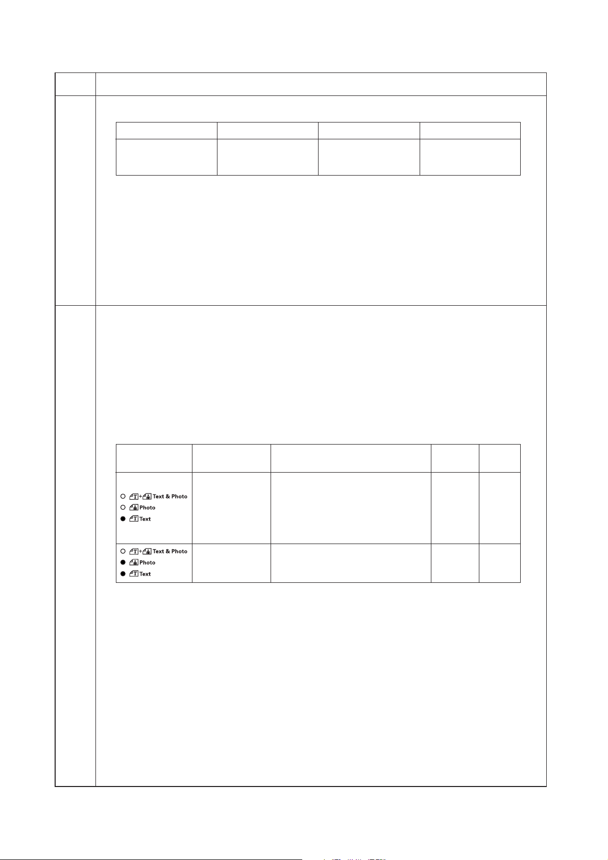
2C9
Maintenance
item No.
U100
(cont.)
U101 Setting the other high voltages
Setting the main charging copy quantity correction
1. Change the setting using the zoom +/– keys.
Display Setting Setting range Initial setting
Exp. 4 (lit) Copy interval 1 to 255 (minute) 60
Exp. 5 (lit) Copy quantity 1 to 255 (10 sheets) 50
Exp. 1 (flashing) Correction amount 0 to 50 (bit) 10
* Copy interval: Sets the time interval from the previous copying. If the time from the previous copying
exceeds this preset value, the copy quantity counter will be reset.
Copy quantity: Sets the copy quantity from which copy quantity correction starts. When the copy quantity
counter reaches this preset value, correction will start.
Correction amount: Sets the correction amount for copy quantity correction.
* Set the values in the range from 5 to 120 minutes for copy interval, from 10 to 2,000 sheets for copy
quantity, and from 5 to 50 bits for correction amount.
2. Press the start key. The value is set.
Completion
Press the stop/clear key when main charger output stops while a selection item is displayed. The indication for
selecting a maintenance item No. appears.
Description
Changes the developing bias clock, the transfer and separation charging output timing.
Purpose
To check the developing bias clock, the transfer and separation charging output timing. Do not change the
preset value.
Method
Press the start key. A selection item appears.
Setting
1. Select the group to be set or checked by lighting image mode LEDs using the image mode selection key.
2. Select the item to be set by lighting a copy exposure indicator using the copy exposure adjustment keys.
Image mode LED
Copy exposure
indicator range setting
Exp. 1 (lit) Developing bias clock frequency 2 to 255 27
Exp. 2 (lit) Developing bias clock duty 1 to 99 45
Exp. 3 (lit) Transfer control voltage (large size) 0 to 255 168
Exp. 4 (lit) Transfer control voltage (small size) 0 to 255 179
Exp. 5 (lit) Transfer charging output OFF timing 0 to 255 38
Exp. 1 (flashing) Transfer charging output ON timing 0 to 255 34
Exp. 1 (lit) Separation control voltage 0 to 255 1
Exp. 2 (lit) Separation charging output ON timing 0 to 255 33
Exp. 3 (lit)
Description
Description
Separation charging output OFF timing
Setting Initial
0 to 255 43
1-4-24
3. Change the setting using the zoom +/– keys.
4. Press the start key. The value is set.
Completion
Press the stop/clear key while a selection item is displayed. The indication for selecting a maintenance item No.
appears.
Page 63
2C9
Maintenance
item No.
U110 Checking/clearing the drum count
Description
Displays the drum counts for checking, clearing or changing a figure.
Purpose
To check the drum status. Also used to clear the count after replacing the drum during regular maintenance.
Since the count was cleared before shipping, do not clear it when installing. A drum count value less than 150K,
however, cannot be cleared.
Method
1. Press the start key.
2. Select the item by lighting a copy exposure indicator using the copy exposure adjustment keys.
Copy exposure indicator Description Setting range Initial setting
Exp. 1 First 3 digits 000 to 999 000
Exp. 2 Last 3 digits 000 to 999 000
Exp. 3 Clearing the count ——— ———
Clearing
1. Light exp. 3.
2. Press the start key. The count is cleared, and the indication for selecting a maintenance item No. appears.
Setting
1. Change the count using the numeric or zoom +/– keys.
2. Press the start key. The count is set, and the indication for selecting a maintenance item No. appears.
Completion
To exit the maintenance mode without changing the count, press the stop/clear key. The indication for selecting
a maintenance item No. appears.
U130 Toner install mode
Description
Executes toner install operation.
Purpose
To operate when installing the machine.
Method
1. Press the start key. “on” appears.
2. Press the start key.
* Installation of toner starts and "9" is indicated in the copy quantity display. Each time one minute elapses,
the indicated value decrements. When the installation is complete, "Gd" will be displayed if the installation
is successful or "nG" will be displayed if it has failed.
3. To stop the installation in the middle, press the stop/clear key.
Completion
Press the stop/clear key. The indication for selecting a maintenance item No. appears.
Description
1-4-25
Page 64

2C9
Maintenance
item No.
U144 Setting toner loading operation
Description
Sets toner loading operation.
Purpose
To run when drum filming (background blur in paper edge section) occurs. Change the setting value to 3 when
poor-quality paper is used and filming occurs frequently.
Method
Press the start key. The screen for selecting an item is displayed.
Setting
1. Change the setting using the zoom +/– keys.
Display Description
0 Toner not loaded
1 Executes toner loading operation before starting driving based on the
printing ratio.
2 Executes toner loading operation between sheets of paper based on the
printing ratio.
3 Executes toner loading operation between sheets of paper every time.
Initial setting: 0
2. Press the start key. The value is set.
Completion
Press the stop/clear key. The indication for selecting a maintenance item No. appears.
U158 Checking/clearing the developing count
Description
Displays the developing count for checking, clearing or changing a figure.
Purpose
To check the developing count.
Method
1. Press the start key.
2. Select the item by lighting a copy exposure indicator using the copy exposure adjustment keys.
Copy exposure indicator Description Setting range Initial setting
Exp. 1 First 3 digits 000 to 999 000
Exp. 2 Last 3 digits 000 to 999 000
Exp. 3 Clearing the count ——— ———
Description
1-4-26
Clearing
1. Light exp. 3.
2. Press the start key. The count is cleared, and the indication for selecting a maintenance item No. appears.
Setting
1. Change the count using the numeric or zoom +/– keys.
2. Press the start key. The count is set, and the indication for selecting a maintenance item No. appears.
Completion
To exit this maintenance item without changing the count, press the stop/clear key. The indication for selecting
a maintenance item No. appears.
Page 65

2C9
Maintenance
item No.
U161 Setting the fixing control temperature
Description
Changes the fixing control temperature.
Purpose
Normally no change is necessary. However, can be used to prevent curling or creasing of paper, or solve a
fixing problem on thick paper.
Method
Press the start key. A selection item appears.
Setting
1. Select the item to be set by lighting a copy exposure indicator using the copy exposure adjustment keys.
2. Change the setting using the zoom +/– keys.
Copy exposure
indicator setting
Exp. 1 (lit) Primary stabilization fixing temperature 120 to 185 (°C) 140
Exp. 2 (lit) Secondary stabilization fixing temperature 120 to 185 (°C) 160
Exp. 3 (lit) Copying operation temperature 1 160 to 220 (°C) 170
Exp. 4 (lit) Copying operation temperature 2 160 to 220 (°C) 180
Exp. 5 (lit) Number of sheets for fixing control 1 to 99 5
Exp. 1 (flashing) Number of sheets for fixing control (thick paper) 1 to 99 20
Copying operation temperature 1: Temperature in copying operation at the start of copying
Copying operation temperature 2: Temperature in copying operation after the specified number of sheets
Number of sheets for fixing control: The number of sheets to be counted for switching from copying
The temperatures are to be set such that Secondary stabilization
3. Press the start key. The value is set.
Completion
To exit this maintenance item without changing the current setting, press the stop/clear key. The indication for
selecting a maintenance item No. appears.
U162 Stabilizing fixing forcibly
Description
Stops the stabilization fixing drive forcibly, regardless of fixing temperature.
Purpose
To forcibly stabilize the machine before the fixing section reaches stabilization temperature.
Method
1. Press the start key. “on” appears.
2. Press the start key. The forced stabilization mode is entered, and stabilization operation stops regardless
of fixing temperature. The indication for selecting a maintenance item No. appears.
To exit the forced stabilization mode, turn the power off and on.
Completion
Press the stop/clear key. The indication for selecting a maintenance item No. appears.
U163 Resetting the fixing problem data
Description
Resets the detection of a service call code indicating a problem in the fixing section.
Purpose
To prevent accidents due to an abnormally high fixing temperature.
Method
1. Press the start key. “CLE” appears.
2. Press the start key. The fixing problem data is initialized.
Completion
Press the stop/clear key. The indication for selecting a maintenance item No. appears.
Description Setting range
Description
Initial
for fixing control have passed
operation temperature 1 to copying operation temperature 2
>
Primary stabilization.
=
1-4-27
Page 66
2C9
Maintenance
item No.
U167 Checking/clearing the fixing count
Description
Displays the fixing count for checking, clearing or changing a figure.
Purpose
To check the fixing count.
Method
1. Press the start key.
2. Select the item by lighting a copy exposure indicator using the copy exposure adjustment keys.
Copy exposure indicator Description Setting range Initial setting
Exp. 1 First 3 digits 000 to 999 000
Exp. 2 Last 3 digits 000 to 999 000
Exp. 3 Clearing the count ——— ———
Clearing
1. Light exp. 3.
2. Press the start key. The count is cleared, and the indication for selecting a maintenance item No. appears.
Setting
1. Change the count using the numeric or zoom +/– keys.
2. Press the start key. The count is set, and the indication for selecting a maintenance item No. appears.
Completion
To exit this maintenance item without changing the count, press the stop/clear key. The indication for selecting
a maintenance item No. appears.
U199 Checking the fixing temperature
Description
Displays the fixing temperature and the ambient temperature.
Purpose
To check the fixing temperature and the ambient temperature.
Method
1. Press the start key.
2. Display each temperature by lighting the respective copy exposure indicator using the copy exposure
adjustment keys.
Copy exposure indicator Description
Exp. 1 Fixing temperature (°C)
Exp. 2 Ambient temperature (°C)
Description
Completion
Press the stop/clear key. The indication for selecting a maintenance item No. appears.
U200 Turning all LEDs on
Description
Turns all the LEDs on the operation panel on.
Purpose
To check if all the LEDs on the operation panel light.
Method
Press the start key. All the LEDs on the operation panel light.
Press the stop/clear key or wait for 10 s. The LEDs turns off, and the indication for selecting a maintenance item
No. appears.
U202 Setting the KMAS host monitoring system
Description
Initializes or operates the KMAS host monitoring system.
This is an optional device which is currently supported only by Japanese specification machines, so no setting
is necessary.
1-4-28
Page 67

2C9
Maintenance
item No.
U203 Operating DP separately
Description
Simulates the original conveying operation separately in the DP.
Purpose
To check the DP.
Method
1. Press the start key.
2. Place an original in the DP if running this simulation with paper.
3. Select the item to be operated using the copy exposure adjustment keys.
Display (copy exposure indicator) Operation
d-P (exp. 1) With paper
d-n (exp. 2) Without paper (continuous operation)
dp2 (exp. 3) With paper (duplex mode)
dn2 (exp. 4) Without paper (duplex mode)
4. Press the start key. The operation starts.
5. To stop continuous operation, press the stop/clear key.
Completion
Press the stop/clear key when the operation stops. The indication for selecting a maintenance item No.
appears.
U204 Setting the presence or absence of a key card or key counter
Description
Sets the presence or absence of the optional key card or key counter.
Purpose
To run this maintenance item if a key card or key counter is installed.
Method
Press the start key.
Setting
1. Select either “on” or “oFF” using the zoom +/– keys.
Display Description
oFF None
on The key card or key counter is installed
Initial setting: oFF
2. Press the start key. The setting is set and the indication for selecting a maintenance item No. appears.
Completion
To exit this maintenance item without changing the current setting, press the stop/clear key. The indication for
selecting a maintenance item No. appears.
U207 Checking the operation panel keys
Description
Checks operation of the operation panel keys.
Purpose
To check operation of all the keys and LEDs on the operation panel.
Method
1. Press the start key.
2. “1” appears on the copy quantity display and the leftmost LED on the operation panel lights.
3. As the keys on the operation panel are pressed in order from the left to right, the figure shown on the copy
quantity display increases in increments of 1. If there is an LED corresponding to the key pressed, the LED
will light.
4. When all the keys on the operation panel have been pressed, all the LEDs light for up to 10 seconds.
5. When the LEDs go off, press the start key. All the LEDs light for 10 seconds again.
Completion
Press the stop/clear key. The indication for selecting a maintenance item No. appears.
Description
1-4-29
Page 68

2C9
Maintenance
item No.
U243 Checking the operation of the DP motors and solenoids
Description
Turns the motors and solenoids in the optional DP on.
Purpose
To check the operation of the DP motors and solenoids.
Method
1. Press the start key.
2. Select the motor or solenoid to be operated using the copy exposure adjustment keys.
3. Press the start key. The operation starts.
Indication (copy exposure indicator)
F-0 (exp. 1) Original feed motor (OFM)
C-0 (exp. 2) Original conveying motor (OCM)
b-S (exp. 3) Switchback feedshift solenoid (SBFSSOL)
P-S (exp. 4) Switchback pressure solenoid (SBPSOL)
4. To turn each motor off, press the stop/clear key.
Completion
Press the stop/clear key when operation stops. The indication for selecting a maintenance item No. appears.
U244 Checking the DP switches
Description
Displays the status of the switches in the optional DP.
Purpose
To check if switches in the DP operate correctly.
Method
1. Press the start key.
2. Turn each switche on and off manually to check the status. When the on-status of a switch is detected, the
LEDs on the operation panel corresponding to the operated switch lights.
LEDs Switch
Auto Exp. Original set switch (OSSW)
Text & Photo DP timing switch (DPTSW)
Photo Original detection switch (ODSW)
Text DP original cover switch (DPOCSW)
Program Original size length switch (OSLSW)
Eco-copy Original switchback switch (OSBSW)
Description
Motor
Completion
Press the stop/clear key. The indication for selecting a maintenance item No. appears.
U250 Setting the maintenance cycle
Description
Displays and changes the maintenance cycle.
Purpose
To check and change the maintenance cycle.
Method
1. Press the start key. The current setting is displayed.
2. Select the item by lighting a copy exposure indicator using the copy exposure adjustment keys.
Copy exposure indicator Description Setting range Initial setting
Exp. 1 First 3 digits 000 to 999 150
Exp. 2 Last 3 digits 000 to 999 000
3. Change the setting using the numeric or zoom +/– keys.
4. Press the start key. The value is set, and the indication for selecting a maintenance item No. appears.
Completion
To exit this maintenance item without changing the current setting, press the stop/clear key. The indication for
selecting a maintenance item No. appears.
1-4-30
Page 69

2C9
Maintenance
item No.
U251 Checking/clearing the maintenance count
Description
Displays, clears and changes the maintenance count.
Purpose
To check the maintenance count. Also to clear the count during maintenance service.
Method
1. Press the start key.
2. Select the item by lighting a copy exposure indicator using the copy exposure adjustment keys.
Copy exposure indicator Description Setting range Initial setting
Exp. 1 First 3 digits 000 to 999 000
Exp. 2 Last 3 digits 000 to 999 000
Exp. 3 Clearing the count ——— ———
Clearing
1. Light exp. 3.
2. Press the start key. The count is cleared, and the indication for selecting a maintenance item No. appears.
Setting
1. Change the count using the numeric or zoom +/– keys.
2. Press the start key. The count is set, and the indication for selecting a maintenance item No. appears.
Completion
To exit this maintenance item without changing the count, press the stop/clear key. The indication for selecting
a maintenance item No. appears.
U252 Setting the destination
Description
Switches the operations and screens of the machine according to the destination.
Purpose
To return the destination setting to its default setting after initializing the backup RAM by running maintenance
item U020.
Method
Press the start key.
Setting
1. Select the destination using the zoom +/– keys.
Display Description
Jpn Metric (Japan) specifications
Inc Inch (North America) specifications
EUP Metric (Europe) specifications
ASA Metric (Asia Pacific) specifications
2. Press the start key. The setting is set, and the machine automatically returns to the same status as when
the power is turned on.
Completion
To exit this maintenance item without changing the current count, press the stop/clear key. The indication for
selecting a maintenance item No. appears.
Supplement
The specified initial settings are provided according to the destinations in the maintenance items below. To
change the initial settings in those items, be sure to run maintenance item U021 after changing the destination.
• Initial setting according to the destinations
Maintenance
item No. Asia Pacific
253 Switching between double and Single Double Double
255 Setting auto clear time 120 s 90 s 90 s
Title Japan Inch
single counts
Description
Europe Metric,
1-4-31
Page 70

2C9
Maintenance
item No.
U253 Switching between double and single counts
Description
Switches the count system for the total counter and other counters.
Purpose
According to user (copy service provider) request, select if A3/11" × 17" paper is to be counted as one sheet
(single count) or two sheets (double count).
Method
Press the start key.
Setting
1. Select the item using the zoom +/– keys.
Display Description
-A3 Double count for A3/11" × 17" paper only
Sin Single count for all size paper
-b4 Double count for B4 size or larger
Initial setting: -A3
2. Press the start key. The setting is set, and the indication for selecting a maintenance item No. appears.
Completion
To exit this maintenance item without changing the current setting, press the stop/clear key. The indication for
selecting a maintenance item No. appears.
U254 Turning auto start function on/off
Description
Selects if the auto start function is turned on.
Purpose
Normally no change is necessary. If incorrect operation occurs, turn the function off: this may solve the
problem.
Method
Press the start key.
Setting
1. Select either “on” or “oFF” using the zoom +/– keys.
Display Description
on Auto start function on
oFF Auto start function off
Initial setting: on
2. Press the start key. The setting is set, and the indication for selecting a maintenance item No. appears.
Completion
To exit this maintenance item without changing the current setting, press the stop/clear key. The indication for
selecting a maintenance item No. appears.
Description
1-4-32
Page 71

2C9
Maintenance
item No.
U255 Setting auto clear time
Description
Sets the time to return to initial settings after copying is complete.
Purpose
To be set according to frequency of use. Set to a comparatively long time for continuous copying at the same
settings, and a comparatively short time for frequent copying at various settings.
Method
Press the start key. The current setting is displayed.
Setting
1. Change the setting using the zoom +/– keys.
Description Setting range Initial setting
Auto clear time 0 to 270 (s) 90
The setting can be changed by 10 s per step.
When set to 0, the auto clear function is cancelled.
2. Press the start key. The value is set, and the indication for selecting a maintenance item No. appears.
Completion
To exit this maintenance item without changing the current setting, press the stop/clear key. The indication for
selecting a maintenance item No. appears.
U258 Switching copy operation at toner empty detection
Description
Selects if continuous copying is enabled after toner empty is detected.
Method
Press the start key. The current setting is displayed.
Setting
1. Select single or continuous copying using the zoom +/– keys.
Display Description
Sin Enables only single copying.
Con Enables single and continuous copying.
Initial setting: Sin
2. Press the start key. The setting is set, and the indication for selecting a maintenance item No. appears.
Completion
To exit this maintenance item without changing the current setting, press the stop/clear key. The indication for
selecting a maintenance item No. appears.
Description
1-4-33
Page 72

2C9
Maintenance
item No.
U260 Changing the copy count timing
Description
Changes the copy count timing for the total counter and other counters.
Purpose
To be set according to user (copy service provider) request.
If a paper jam occurs frequently in the eject section when the number of copies is counted at the time of paper
ejection, copies are provided without copy counts. The copy service provider cannot charge for such copying.
To prevent this, the copy timing should be made earlier.
If a paper jam occurs frequently in the paper conveying or fixing sections when the number of copies is counted
before the paper reaches those sections, copying is charged without a copy being made. To prevent this, the
copy timing should be made later.
Method
Press the start key.
Setting
1. Select the copy count timing using the zoom +/– keys.
Display Description
FEd When secondary paper feed starts
EJE When the paper is ejected
Initial setting: EJE
2. Press the start key. The setting is set, and the indication for selecting a maintenance item No. appears.
Completion
To exit this maintenance item without changing the current setting, press the stop/clear key. The indication for
selecting a maintenance item No. appears.
U265 Setting the destination specifications
Description
Sets whether or not to print the product name on the reports that users print.
Purpose
To be set according to user request.
Method
Press the start key. The current setting appears.
Setting
1. Enter “0” or “2” using the zoom +/– keys.
Setting Description
0 Product name printed
2 Product name not printed
Initial setting: 0
2. Press the start key. The setting is set.
Completion
Press the stop/clear key. The indication for selecting a maintenance item No. appears.
Description
1-4-34
Page 73

2C9
Maintenance
item No.
U332 Setting the size conversion factor
Description
Sets the coefficient of nonstandard sizes in relation to the A4/11" × 81/2" size. The coefficient set here is used to
convert the black ratio in relation to the A4/11" × 8
Purpose
To set the coefficient for converting the black ratio for nonstandard sizes in relation to the A4/11" × 8
copying and printing respectively.
Method
Press the start key. The current setting is displayed.
Setting
1. Change the setting using the zoom +/– keys.
Description Setting range Initial setting
Size conversion factor 0.0 to 3.0 1.0
2. Press the start key. The value is set, and the indication for selecting a maintenance item No. appears.
Completion
To exit this maintenance item without changing the current setting, press the stop/clear key. The indication for
selecting a maintenance item No. appears.
U342 Setting the ejection restriction
Description
Sets or cancels the restriction on the number of sheets to be ejected continuously.
When the restriction is set, the number of sheets that can be ejected continuously to the internal eject tray will
be limited to 250.
Purpose
According to user request, sets or cancels restriction on the number of sheets.
Method
Press the start key.
Setting
1. Select “on” or “oFF” using the zoom +/– keys.
Display Description
on The number of sheets restricted.
oFF The number of sheets not restricted.
Initial setting: on
2. Press the start key. The setting is set. The indication for selecting a maintenance item No. appears.
Completion
To exit this maintenance item without changing the current setting, press the stop/clear key. The indication for
selecting a maintenance item No. appears.
U345 Setting the value for maintenance due indication
Description
Sets when to display a message notifying that the time for maintenance is about to be reached, by setting the
number of copies that can be made before the current maintenance cycle ends.
When the difference between the number of copies of the maintenance cycle and that of the maintenance
count reaches the set value, the message is displayed.
This maintenance mode is effective for only Japanese specification.
Description
1
/2" size and to display the result in user simulation.
1
/2" size for
1-4-35
Page 74
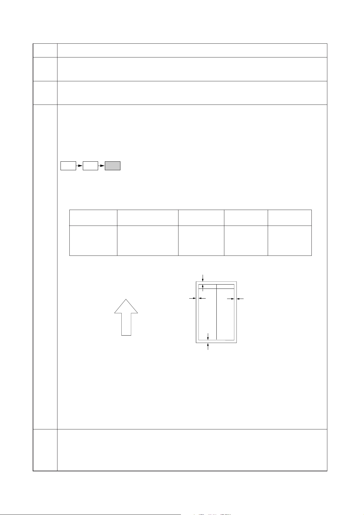
2C9
Maintenance
item No.
Description
U402 Adjusting margins of image printing
Adjustment
See page 1-6-15.
U403 Adjusting margins for scanning an original on the contact glass
Adjustment
See page 1-6-32.
U404 Adjusting margins for scanning an original from the DP
Description
Adjusts margins for scanning the original from the DP.
Purpose
Used if margins are not correct when the optional DP is used.
Caution
Before making this adjustment, ensure that the following adjustments have been made in maintenance mode.
U402 U403 U404
Method
Press the start key.
Setting
1. Select the item by lighting a copy exposure indicator using the copy exposure adjustment keys.
2. Change the setting using the zoom +/– keys.
Copy exposure
indicator value per step
Description Setting range Initial setting
Exp. 1 Left margin 0.0 to 10.0 2.0 0.5 mm
Exp. 2 Leading edge margin 0.0 to 10.0 3.0 0.5 mm
Exp. 3 Right margin 0.0 to 10.0 2.0 0.5 mm
Exp. 4 Trailing edge margin 0.0 to 10.0 2.0 0.5 mm
Increasing the setting makes the margin wider, and decreasing it makes the margin narrower.
Change in
DP leading edge margin (3 ± 2.5 mm)
Ejection direction
(reference)
DP left margin
+1.5
(2.5 mm)
–2.0
DP trailing edge margin
(3 ± 2.5 mm)
Figure 1-4-7 Correct margin amount
3. Press the start key. The value is set.
Interrupt copy mode
While this maintenance item is being performed, copying from an original can be made in interrupt copy mode.
A test copy is output at the reduction ratio of 95%.
Completion
Press the stop/clear key while a selection item is displayed. The indication for selecting a maintenance item No.
appears.
U407 Adjusting the leading edge registration for memory image printing
Adjustment
See page 1-6-13.
DP right margin
+1.5
(2.5 mm)
–2.0
1-4-36
Page 75

2C9
Maintenance
item No.
U901 Checking/clearing copy counts by paper feed locations
Description
Displays or clears copy counts by paper feed locations.
Purpose
To check the time to replace consumable parts. Also to clear the counts after replacing the consumable parts.
Method
1. Press the start key.
2. Select the paper feed location (group No.) for which the count is to be checked or cleared by lighting image
mode LEDs using the image mode selection key.
3. Select the item by lighting a copy exposure indicator using the copy exposure adjustment keys.
Image mode LED Copy exposure
(group No.) indicator
1 Exp. 1 First 3 digits of bypass copy count
Exp. 2 Last 3 digits of bypass copy count
Exp. 3 Clearing the count (CLE)
2 Exp. 1 First 3 digits of the drawer copy count
Exp. 2 Last 3 digits of the drawer copy count
Exp. 3 Clearing the count (CLE)
3 Exp. 1 First 3 digits of the first paper feeder copy count
Exp. 2 Last 3 digits of the first paper feeder copy count
Exp. 3 Clearing the count (CLE)
4 Exp. 1 First 3 digits of the second paper feeder copy count
Exp. 2 Last 3 digits of the second paper feeder copy count
Exp. 3 Clearing the count (CLE)
5 Exp. 1 First 3 digits of the third paper feeder copy count
Exp. 2 Last 3 digits of the third paper feeder copy count
Exp. 3 Clearing the count (CLE)
6 Exp. 1 First 3 digits of the duplex unit copy count
Exp. 2 Last 3 digits of the duplex unit copy count
Exp. 3 Clearing the count (CLE)
7 Exp. 1 Clearing all counts (CLE)
Description
Copy quantity display (count value)
: Off, : On, : Flashing
Note: When no optional paper feed device is installed, the counts corresponding to optional paper feed
devices will not appear.
Clearing copy counts by paper feed locations
1. Select the paper feed location to clear the count.
2. Light exp. 3 using the copy exposure adjustment key.
3. Press the start key. The count is cleared.
Clearing copy counts for all paper feed locations
1. Select group 7.
2. Press the start key. The counts are cleared.
Completion
Press the stop/clear key. The indication for selecting a maintenance item No. appears.
1-4-37
Page 76

2C9
Maintenance
item No.
U903 Checking/clearing the paper jam counts
Description
Displays or clears the jam counts by jam locations.
Purpose
To check the paper jam status. Also to clear the jam counts after replacing consumable parts.
Method
1. Press the start key.
2. Display the jam code to check the count using the copy exposure adjustment keys.
3. Press the start key. The jam count appears. If the jam count is a 4-digit value, the first digit and the last 3
digits are displayed alternately.
4. Press the stop/clear key. The jam code appears again.
Copy exposure
J10
Stop/
clear key
10
adjustment keys
Start key
Copy exposure
adjustment keys
Clearing all jam counts
1. Display “CLE” using the copy exposure adjustment keys. Jam counts cannot be cleared individually.
2. Press the start key. The counts are cleared.
Completion
Press the stop/clear key. The indication for selecting a maintenance item No. appears.
U904 Checking/clearing the service call counts
Description
Displays or clears the service call code counts by types.
Purpose
To check the service call code status by types. Also to clear the service call code counts after replacing
consumable parts.
Method
1. Press the start key.
2. Display the service call code to check the count using the copy exposure adjustment keys.
3. Press the start key. The service call count appears. If the service call count is a 4-digit value, the first digit
and the last 3 digits are displayed alternately.
4. Press the stop/clear key. The service call code appears again.
Description
J11
Stop/
clear key
100
Figure 1-4-8
Copy exposure
adjustment keys
Start key
CLE
1-4-38
Stop/
clear key
010
10
Copy exposure
adjustment keys
Start key
Copy exposure
adjustment keys
011
Stop/
clear key
100
Copy exposure
adjustment keys
Start key
Figure 1-4-9
Clearing counts by service call codes
1. Display the service call code to clear the count.
2. Press the reset key. The count is cleared.
Clearing all service call counts
1. Display “CLE” using the copy exposure adjustment keys.
2. Press the start key. The counts are cleared.
Completion
Press the stop/clear key. The indication for selecting a maintenance item No. appears.
CLE
Page 77
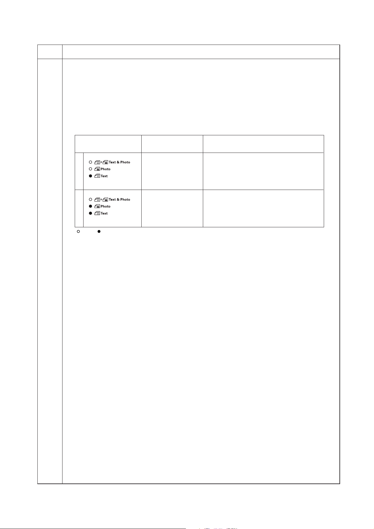
2C9
Maintenance
item No.
U905 Checking/clearing counts by the DP
Description
Displays or clears the counts of the DP.
Purpose
To check the use of the DP. Also to clear the counts after replacing consumable parts.
Method
1. Press the start key.
2. Select the count (group No.) to be checked or cleared by lighting image mode LEDs using the image mode
selection key.
3. Select the item by lighting a copy exposure indicator using the copy exposure adjustment keys.
Image mode LED Copy exposure
(group No.) indicator
1 Exp. 1 First 3 digits of the number of original
Exp. 2 Last 3 digits of the number of original
Exp. 3 Clearing the count (CLE)
2 Exp. 1 First 3 digits of the double-sided original feed
Exp. 2 Last 3 digits of the double-sided original feed
Exp. 3 Clearing the count (CLE)
: Off, : On
Clearing
1. Select the count to be cleared.
2. Light exp. 3 using the copy exposure adjustment keys.
3. Press the start key. The count is cleared.
Completion
Press the stop/clear key. The indication for selecting a maintenance item No. appears.
Description
Copy quantity display (count value)
replacement
replacement
count
count
1-4-39
Page 78

2C9
Maintenance
item No.
U908 Checking the total count
Description
Display the total count value.
Purpose
To check the total count value.
Method
1. Press the start key.
2. Select the item by lighting a copy exposure indicator using the copy exposure adjustment keys.
Copy exposure indicator Copy quantity display (count value)
Exp. 1 First 3 digits of the total count
Exp. 2 Last 3 digits of the total count
Completion
Press the stop/clear key. The indication for selecting a maintenance item No. appears.
U910 Clearing the black ratio data
Description
Clears the accumulated black ratio data for A4/11" × 81/2" sheets.
Purpose
To clear data as required at times such as during maintenance service.
Method
1. Press the start key.
2. Select “on” using the zoom +/– keys.
Display Operation
––– Canceling the clearing
on Executing the clearing
3. Press the start key. The accumulated black ratio data is cleared.
Completion
To exit this maintenance item without clearing the data, press the stop/clear key. The indication for selecting a
maintenance item No. appears.
Description
1-4-40
Page 79

2C9
Maintenance
item No.
U911 Checking/clearing copy counts by paper size
Description
Displays or clears the paper feed count value by paper size.
Purpose
To check the time to replace consumable parts. Also to clear the counts after replacing the consumable parts.
Method
1. Press the start key.
2. Select the paper size (group No.) for which the count is to be checked or cleared by lighting image mode
LEDs using the image mode selection key.
3. Select the item by lighting a copy exposure indicator using the copy exposure adjustment keys.
Image mode LED (group No.) Copy exposure indicator Copy quantity display (count value)
1
2
3
Exp. 1 (lit) “-A3” display the A3 size
Exp. 2 (lit) First 3 digits of A3 size copy count
Exp. 3 (lit) Last 3 digits of A3 size copy count
Exp. 4 (lit) Clearing the count (CLE)
Exp. 1 (lit) “-b4” display the B4 size
Exp. 2 (lit) First 3 digits of B4 size copy count
Exp. 3 (lit) Last 3 digits of B4 size copy count
Exp. 4 (lit) Clearing the count (CLE)
Exp. 1 (lit) “-A4” display the A4 size
Exp. 2 (lit) First 3 digits of A4 size copy count
Exp. 3 (lit) Last 3 digits of A4 size copy count
Exp. 4 (lit) Clearing the count (CLE)
Description
4
5
6
7
8
Exp. 1 (lit) “-b5” display the B5 size
Exp. 2 (lit)
Exp. 3 (lit)
Exp. 4 (lit) Clearing the count (CLE)
Exp. 1 (lit) “-A5” display the A5 size
Exp. 2 (lit)
Exp. 3 (lit)
Exp. 4 (lit) Clearing the count (CLE)
Exp. 1 (lit) “-A6” display the A6 size
Exp. 2 (lit)
Exp. 3 (lit)
Exp. 4 (lit) Clearing the count (CLE)
Exp. 1 (lit) “-Fo” display the FOLIO size
Exp. 2 (lit)
Exp. 3 (lit)
Exp. 4 (lit) Clearing the count (CLE)
Exp. 1 (lit) “-Ld” display the Ledger size
Exp. 2 (lit)
Exp. 3 (lit)
Exp. 4 (lit) Clearing the count (CLE)
First 3 digits of FOLIO size copy count
Last 3 digits of FOLIO size copy count
First 3 digits of Legal size copy count
Last 3 digits of Legal size copy count
First 3 digits of Letter size copy count
Last 3 digits of Letter size copy count
First 3 digits of FOLIO size copy count
Last 3 digits of FOLIO size copy count
First 3 digits of Ledger size copy count
Last 3 digits of Ledger size copy count
: Off : On : Flashing
1-4-41
Page 80

2C9
Maintenance
item No.
U911
Description
Image mode LED (group No.) Copy exposure indicator Copy quantity display (count value)
9
10
11
12
13
Exp. 1 (lit) “-Lg” display the Legal size
Exp. 2 (lit)
Exp. 3 (lit)
Exp. 4 (lit) Clearing the count (CLE)
Exp. 1 (lit) “-Lt” display the Letter size
Exp. 2 (lit)
Exp. 3 (lit)
Exp. 4 (lit) Clearing the count (CLE)
Exp. 1 (lit) “-St” display the Statement size
Exp. 2 (lit)
Exp. 3 (lit)
Exp. 4 (lit) Clearing the count (CLE)
Exp. 1 (lit) “-ot” display the other size
Exp. 2 (lit) First 3 digits of other size copy count
Exp. 3 (lit) Last 3 digits of other size copy count
Exp. 4 (lit) Clearing the count (CLE)
Exp. 1 (lit) Clearing all counts (CLE)
First 3 digits of
Last 3 digits of
First 3 digits of Letter size copy count
Last 3 digits of Letter size copy count
First 3 digits of Statement size copy count
Last 3 digits of Statement size copy count
Legal
size copy count
Legal
size copy count
: Off : On : Flashing
Clearing copy counts by paper size
1. Select the paper size to clear the count.
2. Display “CLE” using the copy exposure adjustment keys.
3. Press the start key. The count is cleared.
Clearing copy counts for all paper size
1. Select group 13.
2. Press the start key. The counts are cleared.
Completion
Press the stop/clear key. The indication for selecting a maintenance item No. appears.
U927 Clearing accounting counter
Description
Clears the total count and the scanner count. The counts, however, can be cleared only one time. If either of the
total count or the scanner count exceeds 1,000, this mode cannot be run.
Purpose
To start the counters with value 0 when installing the machine.
Method
1. Press the start key. If the counters have been already cleared or either of the total counter or the scanner
counter exceeds 1,000, this mode cannot be run and “nG” is displayed.
2. Select “on” using the zoom +/– keys.
Display Operation
––– Canceling the clearing
on Executing the clearing
3. Press the start key. The accounting counter is cleared.
Completion
To exit this maintenance item without clearing the data, press the stop/clear key. The indication for selecting a
maintenance item No. appears.
1-4-42
Page 81

2C9
Maintenance
item No.
U928 Checking/clearing the machine life count
Description
Displays the machine life counts for checking a figure.
Purpose
To check machine status. Do not clear or change the preset value.
Method
1. Press the start key.
2. Select the item by lighting a copy exposure indicator using the copy exposure adjustment keys.
Copy exposure indicator Description Setting range Initial setting
Exp. 1 First 3 digits 000 to 999 000
Exp. 2 Last 3 digits 000 to 999 000
Exp. 3 Clearing the count ——— ———
Clearing
1. Light exp. 3.
2. Press the start key. The count is cleared, and the indication for selecting a maintenance item No. appears.
Setting
1. Change the count using the numeric or zoom +/– keys.
2. Press the start key. The count is set, and the indication for selecting a maintenance item No. appears.
Completion
Press the stop/clear key. The indication for selecting a maintenance item No. appears.
U990 Checking/clearing the time for the exposure lamp to light
Description
Displays or clears the accumulated time for the exposure lamp to light.
Purpose
To check duration of use of the exposure lamp. Also to clear the accumulated time for the lamp after
replacement.
Method
1. Press the start key.
2. Select the item by lighting a copy exposure indicator using the copy exposure adjustment keys.
Copy exposure indicator Copy quantity display
Exp. 1 First 3 digits of the lamp-on time (minutes)
Exp. 2 Last 3 digits of the lamp-on time (minutes)
Exp. 3 Clearing the lamp-on time (CLE)
Description
Clearing
1. Light exp. 3.
2. Press the start key. The accumulated time is cleared, and the indication for selecting a maintenance item
No. appears.
Completion
To exit this maintenance item without changing the accumulated time, press the stop/clear key. The indication
for selecting a maintenance item No. appears.
1-4-43
Page 82

2C9
Maintenance
item No.
U991 Checking the scanner count
Description
Display the scanner count value.
Purpose
To check the scanner count value.
Method
1. Press the start key.
2. Change the indication of the copy quantity display by lighting a copy exposure indicator using the copy
exposure adjustment keys.
Copy exposure indicator Copy quantity display (count value)
Exp. 1 First 3 digits of the scanner count
Exp. 2 Last 3 digits of the scanner count
Completion
Press the stop/clear key. The indication for selecting a maintenance item No. appears.
U993 Outputting a VTC-PG pattern
Description
Selects and outputs a VTC-PG pattern created in the copier.
Purpose
When performing respective image printing adjustments, used to check the machine status apart from that of
the scanner with a non-scanned output VTC-PG pattern.
Method
1. Press the start key.
2. Select the VTC-PG pattern to be output using the copy exposure adjustment keys.
Display PG pattern to be output Purpose
0 • Center line adjustment
Description
1
2
3. Press the interrupt key. The machine enters the PG pattern output mode.
4. Press the start key. A VTC-PG pattern is output.
Completion
Press the stop/clear key. The indication for selecting a maintenance item No. appears.
• Lateral squareness adjustment
• Magnification adjustment
• Checking the fixing performance (fixing pressure)
1-4-44
Page 83

2C9
1-4-2 Copier management
In addition to a maintenance function for service, the copier is equipped with a management function which can be operated
by users (mainly by the copier administrator). In this copier management mode, settings such as default settings can be
changed.
(1) Using the copier management mode
• Executing a department management item • Executing a default setting item
Start
Press both of the copy
exposure adjustment keys
and manegement key for 3 s.
Select an item using the zoom
+/– keys or numeric keys.
Press the enter key.
Execute the department
management item
(page 1-4-46).
Select “d00” and
press the enter key.
Start
Press both of the copy exposure adjustment keys for 3 s.
Select an item using the zoom
+/– keys or numeric keys.
Press the enter key.
Execute the default
setting item (page 1-4-46).
Select “F00” and
press the enter key.
End
1-4-45
Page 84

2C9
(2) Setting department management items
Management on/off setting
1. Select “d01” and press the enter key.
2. Select “ON” or “OFF” and press the enter key.
Setting range: ON (set)/OFF (no setting)
Management code registration
1. Select “d02” and press the enter key.
2. Enter a department code using the numeric
keys and press the enter key.
Setting range: 0 to 99999999
Management code deletion
1. Select “d03” and press the enter key.
2. Enter the department code to be deleted using
the numeric keys
3. Select “YES” or “NO” and press the enter key.
Setting range: YES (delete)/NO (no deletion)
(3) Copy default
User status report
Prints the details of the default settings.
1. Select “F01” and press the enter key.
If A4/11" × 8
1
/2" paper is present, the list is
automatically printed out. Otherwise, select
the paper source and press the start key.
Original image quality
Selects the image quality at power-on.
1. Select “F02” and press the enter key.
2. Select the image mode and press the enter
key.
Setting range: 1 (text & photo)/2 (photo)/
3 (text)
Exposure mode
Selects the exposure mode at power-on.
1. Select “F03” and press the enter key.
2. Select the exposure mode and press the enter
key.
Setting range: 1 (manual)/2 (auto)
Eco-copy
Selects the eco-copy mode at power-on.
1. Select “F04” and press the enter key.
2. Select “ON” or “OFF” and press the enter key.
Setting range: ON (enabled)/OFF (disabled)
Exposure steps
Sets the number of exposure steps for the manual
exposure mode.
1. Select “F05” and press the enter key.
2. Select “1 step” or “0.5 step” and press the
enter key.
Setting range: 1 (1 step)/2 (0.5 step)
Clearing management count
1. Select “d04” and press the enter key.
2. Select “YES” or “NO” and press the enter key.
Setting range: YES (clear)/NO (do not clear)
Outputing the management list
1. Select “d05” and press the enter key.
If A4/11" × 8
1
/2" paper is present, the list is
automatically printed out. Otherwise, select
the paper source and press the start key.
Auto exposure adjustment
Adjusts the exposure for the auto exposure mode.
1. Select “F06” and press the enter key.
2. Select the setting and press the enter key.
Setting range: 1 (lightest) to 7 (darkest)
Text and photo mode exposure adjustment
Adjusts the exposure to be used when text and
photo original is selected for the image mode.
1. Select “F07” and press the enter key.
2. Select the setting and press the enter key.
Setting range: 1 (lightest) to 7 (darkest)
Photo exposure adjustment
Adjusts the exposure to be used when photo
original is selected for the image mode.
1. Select “F08” and press the enter key.
2. Select the setting and press the enter key.
Setting range: 1 (lightest) to 7 (darkest)
Text exposure adjustment
Adjusts the exposure to be used when text original
is selected for the image mode.
1. Select “F09” and press the enter key.
2. Select the setting and press the enter key.
Setting range: 1 (lightest) to 7 (darkest)
Black-line correction
Reduces black lines that may be caused when the
DP is used.
1. Select “F10” and press the enter key.
2. Select the setting and press the enter key.
Setting range: 1 (off)/2 (weak)/3 (strong)
1-4-46
Page 85

2C9
Photo processing
Select the image processing method for photo
originals.
1. Select “F11” and press the enter key.
2. Select the setting and press the enter key.
Setting range: 1 (error diffusion)/2 (dithering)
Setting this to error diffusion when copying
originals with text and photo and dithering
when copying originals with mainly photos.
Ground color adjustment
The ground color adjusting after copying.
1. Select “F12” and press the enter key.
2. Select the setting and press the enter key.
Setting range: 1 (lightest) to 5 (darkest)
Paper selection
Select the auto paper select function based on the
original size or priority cassette selection.
1. Select “F13” and press the enter key.
2. Select the setting and press the enter key.
Setting range: 1 (auto paper selection)/
2 (selected drawer)
Selected drawer
Selects the drawer that is to be automatically be
given priority for use.
1. Select “F14” and press the enter key.
2. Select the default drawer and press the enter
key.
Setting range: 1 (drawer)/2 (first paper feeder)/
3 (second paper feeder)/4 (third paper feeder)
Note: This setting item will not be displayed if
no optional paper feeder is installed.
Auto drawer switching
Sets whether the auto drawer switching function is
available.
1. Select “F15” and press the enter key.
2. Select “ON” or “OFF” and press the enter key.
Setting range: ON (enabled)/OFF (disabled)
Note: This setting item will not be displayed if
no optional paper feeder is installed.
AMS mode
Selects whether auto magnification selection or
100% magnification is to be given priority when the
sizes of the original and copy paper are different.
1. Select “F16” and press the enter key.
2. Select “ON” or “OFF” and press the enter key.
Setting range: ON (enabled)/OFF (disabled)
Drawer paper size (drawer 2)
Sets the paper size for the first paper feeder so
that it will be automatically selected.
1. Select “F18” and press the enter key.
2. Select the paper size and press the enter key.
Setting range: AtC (auto detection metric)/
AtI (auto detection inch)/o2r (oficio2)
Note: This setting item will not be displayed if
no optional paper feeder is installed.
Drawer paper size (drawer 3)
Sets the paper size for the second paper feeder so
that it will be automatically selected.
1. Select “F19” and press the enter key.
2. Select the paper size and press the enter key.
Setting range: AtC (auto detection metric)/
AtI (auto detection inch)/o2r (oficio2)
Note: This setting item will not be displayed if
no optional paper feeder is installed.
Drawer paper size (drawer 4)
Sets the paper size for the third paper feeder so
that it will be automatically selected.
1. Select “F20” and press the enter key.
2. Select the paper size and press the enter key.
Setting range: AtC (auto detection metric)/
AtI (auto detection inch)/o2r (oficio2)
Note: This setting item will not be displayed if
no optional paper feeder is installed.
Bypass tray paper size
Sets the paper size for the bypass tray so that it will
be automatically selected.
1. Select “F21” and press the enter key.
2. Select the paper size and press the enter key.
Setting range: Uni (universal size)/A3r (A3/
1
11" × 17")/A4r (A4/8
vertical/11" × 8
1
b4r (B4/8
/2" × 14")/b5r (B5)/Cu1 (custom 1)/
/2" × 11")/A4E (A4
1
/2")/A5r (A5/51/2" × 81/2")/
Cu2 (custom 2)
Custom 1 size
Sets the size of the paper to be set to the custom 1
size.
1. Select “F22” and press the enter key.
2. Select the paper size and press the enter key.
Setting range: b6r (B6)/A6r (A6)/Pos
(postcard)/Ldr (ledger/11" × 17")/Lgr (legal/
1
/2" × 14")/Ltr (letter/81/2" × 11")/LtE (letter
8
vertical/11" × 8
1
/2")/Str (statement)/o2r
(oficio2)/CPF (11" × 15")/InP (irregular size)
Drawer paper size (drawer 1)
Sets the paper size for the drawer so that it will be
automatically selected.
1. Select “F17” and press the enter key.
2. Select the paper size and press the enter key.
Setting range: AtC (auto detection metric)/
AtI (auto detection inch)/o2r (oficio2)
1-4-47
Page 86

2C9
Custom 2 size
Sets the size of the paper to be set to the custom 2
size.
1. Select “F23” and press the enter key.
2. Select the paper size and press the enter key.
Setting range: b6r (B6)/A6r (A6)/Pos
(postcard)/Ldr (ledger/11" × 17")/Lgr (legal/
1
/2" × 14")/Ltr (letter/81/2" × 11")/LtE (letter
8
vertical/11" × 8
1
/2")/Str (statement)/o2r
(oficio2)/CPF (11" × 15")/InP (irregular size)
Copy limit
Sets the number of copies limit for multiple copying.
1. Select “F24” and press the enter key.
2. Enter the setting and press the enter key.
Setting range: 1 to 250 copies
Duplex copy reverse-side rotation setting
Select whether or not the image on the reverse side
is rotated 180 degrees in the duplex copy mode.
1. Select “F25” and press the enter key.
2. Select “ON” or “OFF” and press the enter key.
Setting range: ON (rotate)/OFF (no rotation)
Margin width
Sets the default setting of the margin width for the
margin copying.
1. Select “F26” and press the enter key.
2. Select the setting and press the enter key.
Setting range: 1 to 18 mm
Border erase width
Sets the default setting of the border erase width
for the border erase mode.
1. Select “F27” and press the enter key.
2. Select the setting and press the enter key.
Setting range: 6 mm/12 mm/18 mm
4 in 1 layout setting
Sets the layoout for the order in which the originals
will appear in the 4 in 1 layout mode.
1. Select “F28” and press the enter key.
2. Select the setting and press the enter key.
Setting range: 1 to 4
Aggregate copy borderline
Selects the type of borderline to be usedf in the
layout mode.
1. Select “F29” and press the enter key.
2. Select the setting and press the enter key.
Setting range: 1 (no borderline)/2 (solid line)/
3 (dotted line)
Rotate sort
Sets whether or not to perform rotate sorting when
the sort mode is selected.
1. Select “F30” and press the enter key.
2. Select “ON” or “OFF” and press the enter key.
Setting range: ON (enabled)/OFF (disabled)
1-4-48
Silent mode transition time
Set the silent mode transition time after copying.
1. Select “F31” and press the enter key.
2. Select the setting and press the enter key.
Setting range: 0 sec/5 sec/10 sec/
15 sec/30 sec
Auto clear setting
Sets whether the auto clear function is available.
1. Select “F32” and press the enter key.
2. Select “ON” or “OFF” and press the enter key.
Setting range: ON (enabled)/OFF (disabled)
Auto off setting
Sets whether the auto off function is available.
1. Select “F33” and press the enter key.
2. Select “ON” or “OFF” and press the enter key.
Setting range: ON (enabled)/OFF (disabled)
Auto clear time
Sets the auto clear time.
1. Select “F34” and press the enter key.
2. Select the setting and press the enter key.
Setting range: 10 to 270 sec
Auto preheat time
Sets the auto preheat time.
1. Select “F35” and press the enter key.
2. Select the setting and press the enter key.
Setting range: 1 min/5 min/15 min/30 min/45
min/60 min/90 min/120 min/180 min/240 min
Auto shutoff time
Sets the auto shutoff time.
1. Select “F36” and press the enter key.
2. Select the setting and press the enter key.
Setting range: 15 min/30 min/45 min/60 min/
90 min/120 min/180 min/240 min
Alarm
The alarm can be set to sound when errors occur.
1. Select “F37” and press the enter key.
2. Select “ON” or “OFF” and press the enter key.
Setting range: ON (sound alarm)/
OFF (no alarm)
Toner coverage report
Prints out a report that shows the number of copies
made and the blackness ratio for each paper size.
1. Select “F38” and press the enter key.
1
If A4/11" × 8
/2" paper is present, the list is
automatically printed out. Otherwise, select
the paper source and press the start key.
Page 87

2C9
1-5-1 Paper misfeed detection
(1) Paper misfeed indication
When a paper misfeed occurs, the copier immediately stops copying and displays the jam location on the operation panel.
Paper misfeed counts sorted by the detection condition can be checked in maintenance item U903.
To remove paper jammed in the copier, open the front cover, left cover, or pull the drawer out.
To remove original jammed in the DP, open the DP original cover.
Paper misfeed detection can be reset by opening and closing the respective covers to turn safety switch off and on.
Figure 1-5-1
1 Misfeed in the paper feed section
2 Misfeed in the paper conveying section
3 Misfeed in the optional DP
4 Misfeed in the optional paper feeder
1-5-1
Page 88

2C9
(2) Paper misfeed detection conditions
OCM OFM
DPTSW
ESW
FSSW
OSBSW
DUPPCSW
DUPFCL
BYPPFCL
DFSW1
DFSW2
RM
RSW
PFCL
DPFCL1
DPFCL2
DPFCL3
1-5-2
Figure 1-5-2
Page 89

Section Jam code Description Conditions
System
00
No paper feed
When the power switch is turned on, the machine detects
activation of the registration switch (RSW), the exit switch
(ESW) or the feedshift switch (FSSW).
2C9
Paper feed
section
04
05
10
11
12
13
Cover open JAM
Secondary paper feed
timeout
No paper feed from the
bypass tray
No paper feed from the
drawer 1
No paper feed from the
drawer 2* (first paper
feeder)
No paper feed from the
drawer 3* (second paper
feeder)
A cover open state is detected during copying.
When the machine waits for secondary paper feed, 15 s or
more have elapsed.
The registration switch (RSW) does not turn on within 1680
ms of the bypass paper feed clutch (BYPPFCL) turning on;
the clutch is then successively held off for 1 s and turned
back on once, but the switch again fails to turn on within
1680 ms.
The registration switch (RSW) does not turn on within 1254
ms of the paper feed clutch (PFCL) turning on; the clutch is
then successively held off for 1 s and turned back on once,
but the switch again fails to turn on within 1254 ms.
The registration switch (RSW) does not turn on within 2780
ms of the drawer paper feed clutch 1 (DPFCL1)* turning on;
the clutch is then successively held off for 1 s and turned
back on once, but the switch again fails to turn on within
2780 ms.
The drawer feed switch 1 (DFSW1)* does not turn on within
2490 ms of the drawer paper feed clutch 2 (DPFCL2)* turning on; the clutch is then successively held off for 1 s and
turned back on once, but the switch again fails to turn on
within 2490 ms.
Paper conveying
section
14
15
16
20
21
No paper feed from the
drawer 4* (third paper
feeder)
Misfeed in vertical paper
conveying 1
Misfeed in vertical paper
conveying 2
Multiple sheets in the bypass tray
Multiple sheets in the
drawer 1
The drawer feed switch 2 (DFSW2)* does not turn on within
2490 ms of the drawer paper feed clutch 3 (DPFCL3)* turning on; the clutch is then successively held off for 1 s and
turned back on once, but the switch again fails to turn on
within 2490 ms.
The registration switch (RSW) does not turn on within 2340
ms of drawer feed switch 1 (DFSW1)* turning on.
The drawer feed switch 1 (DFSW1)* does not turn off within
2050 ms of drawer feed switch 2 (DFSW2)* turning on.
The drawer feed switch 1 (DFSW1)* does not turn off within
2050 ms of drawer feed switch 2 (DFSW2)* turning off.
The drawer feed switch 1 (DFSW1)* does not turn on within
2050 ms of drawer feed switch 2 (DFSW2)* turning on.
The registration switch (RSW) does not turn off within 5320
ms of registration switch (RSW) turning on.
The registration switch (RSW) does not turn off within 1680
ms of bypass paper feed clutch (BYPPFCL) turning on.
The registration switch (RSW) does not turn off within 5320
ms of registration switch (RSW) turning on.
The registration switch (RSW) does not turn off within 1254
ms of paper feed clutch (PFCL) turning on.
*: Optional.
1-5-3
Page 90

2C9
Section Jam code Description Conditions
Paper conveying
section
22
Multiple sheets in the
drawer 2* (first paper
feeder)
The registration switch (RSW) does not turn off within 4320
ms of registration switch (RSW) turning on.
The registration switch (RSW) does not turn off within 2482
ms of drawer paper feed clutch 1 (DPFCL1)* turning on.
Transfer
section
Fixing section
Exit section
Feedshift
section
23
24
30
40
50
52
Multiple sheets in the
drawer 3* (second paper
feeder)
Multiple sheets in the
drawer 4* (third paper
feeder)
Misfeed in registration/
transfer section
Misfeed in the fixing section
Misfeed in the exit section
Misfeed in the feedshift
section
The drawer feed switch 1 (DFSW1)* does not turn off within
5267 ms of drawer feed switch 1 (DFSW1)* turning on.
The rdrawer feed switch 1 (DFSW1)* does not turn off within
2223 ms of drawer paper feed clutch 2 (DPFCL2)* turning
on.
The drawer feed switch 2 (DFSW2)* does not turn off within
5267 ms of drawer feed switch 2 (DFSW2)* turning on.
The rdrawer feed switch 2 (DFSW2)* does not turn off within
2223 ms of drawer paper feed clutch 3 (DPFCL3)* turning
on.
A signal other than secondary paper feed start is received
when the machine is waiting for secondary paper feed.
The exit switch (ESW) does not turn on within 3020 ms of the
registration motor (RM) turning on.
The exit switch (ESW) does not turn off within 3020 ms of the
registration switch (RSW) turning off.
The exit switch (ESW) does not turn on within 3020 ms of the
registration motor (RM) turning on.
The feedshift switch (FSSW) does not turn on within 5320
ms of feedshift switch (FSSW) turning on.
Duplex
section
DP
60
61
70
Misfeed in duplex paper
conveying section*
Misfeed in duplex exit
section*
No original feed*
The feedshift switch (FSSW) does not turn off within 1530
ms of paper switchback.
The feedshift switch (FSSW) does not turn on within 1530
ms of paper switchback.
The duplex paper conveying switch (DUPPCSW)* does not
turn off within 3280 ms of the feedshift switch (FSSW) turning on.
The duplex paper conveying switch (DUPPCSW)* does not
turn on within 3280 ms of the feedshift switch (FSSW) turning on.
The duplex paper conveying switch (DUPPCSW)* does not
turn off within 3280 ms of the feedshift switch (FSSW) turning off.
The registration switch (RSW) does not turn on within 1760
ms of the duplex paper conveying switch (DUPPCSW)* turning on.
The registration switch (RSW) does not turn off within 1760
ms of the duplex paper conveying switch (DUPPCSW)* turning off.
During the primary feed of the second original in the singlesided or double-sided original mode, even if retry operation is
performed five times, primary original feed is not performed.
*: Optional.
1-5-4
Page 91

Section Jam code Description Conditions
DP 71
An original jam in the
original conveying section 1*
During the secondary original feed in the single-sided or
double-sided original mode, the DP timing switch (DPTSW)*
does not turn off within 6500 ms of the original conveying
motor (OCM)* turning on.
2C9
72
73
74
75
An original size error
jam*
An original jam in the
original conveying section 2*
An original jam in the
original conveying section 3*
An original jam in the
original switchback section*
During the secondary original feed in the single-sided or
double-sided original mode, the DP timing switch (DPTSW)*
does turn off within 750 ms of the original conveying motor
(OCM)* turning on.
During scanning of the second side or reversing of the original for ejection in the double-sided original mode, the DP timing switch (DPTSW)* does not turn off within 6500 ms of the
original conveying motor (OCM)* turning on.
During scanning of the second side or reversing of the original for ejection in the double-sided original mode, the DP timing switch (DPTSW)* does not turn on within 750 ms of the
original conveying motor (OCM)* turning on.
During the switchback operation of an original in the doublesided original mode, the original switchback switch (OSBSW)
*does not turn on within 1300 ms of the original conveying
motor (OCM)* turning on.
*: Optional.
1-5-5
Page 92
2C9
(3) Paper misfeeds
• Copier
Problem Causes/check procedures Corrective measures
(1)
A paper jam in the
paper feed, paper
conveying or exit
section is indicated
as soon as the
power switch is
turned on.
Jam code 00
A piece of paper torn from
copy paper is caught
around registration switch,
exit sensor or feedshift
switch.
Defective registration
switch.
Defective exit switch.
Check visually and remove it, if any.
Run maintenance item U031 and turn registration switch on and
off manually. Replace registration switch if indication of the corresponding switch is not light.
Run maintenance item U031 and turn exit switch on and off
manually. Replace exit switch if indication of the corresponding
switch is not light.
(2)
A paper jam in the
paper feed section
is indicated during
copying (no paper
feed from the bypass tray).
Jam code 10
(3)
A paper jam in the
paper feed section
is indicated during
copying (no paper
feed from the
drawer 1).
Jam code 11
Defective feedshift switch.
Paper on the bypass tray
is extremely curled.
Check if the bypass paper
feed pulley is deformed.
Broken registration switch
actuator.
Defective registration
switch.
Check if the bypass paper
feed clutch malfunctions.
Electrical problem with the
bypass paper feed clutch.
Paper in the drawer is extremely curled.
Check if the paper feed
pulley, separation pulley or
forward pulley is deformed.
Broken registration switch
actuator.
Run maintenance item U031 and turn feedshift switch on and off
manually. Replace feedshift switch if indication of the corresponding switch is not light.
Change the paper.
Check visually and replace any deformed pulley.
Check visually and replace registration switch if its actuator is
broken.
Run maintenance item U031 and turn registration switch on and
off manually. Replace registration switch if indication of the corresponding switch is not light.
Run maintenance item U032 and select the bypass paper feed
clutch to be turned on and off. Check the status and remedy if
necessary.
Check (see page 1-5-29).
Change the paper.
Check visually and replace any deformed pulley.
Check visually and replace registration switch if its actuator is
broken.
1-5-6
Defective registration
switch.
Check if the paper feed
clutch malfunctions.
Electrical problem with the
paper feed clutch.
Run maintenance item U031 and turn registration switch on and
off manually. Replace registration switch if indication of the corresponding switch is not light.
Run maintenance item U032 and select the paper feed clutch to
be turned on and off. Check the status and remedy if necessary.
Check (see page 1-5-29).
Page 93
Problem Causes/check procedures Corrective measures
(4)
A paper jam in the
paper feed section
is indicated during
copying (no paper
feed from the
drawer 2).
Jam code 12
Paper in the first paper
feeder is extremely curled.
Check if the paper feed
pulley, separation pulley or
forward pulley in the first
paper feeder is deformed.
Broken registration switch
actuator.
Change the paper.
Check visually and replace any deformed pulley.
Check visually and replace registration switch if its actuator is
broken.
2C9
(5)
A paper jam in the
paper feed section
is indicated during
copying (no paper
feed from the
drawer 3).
Jam code 13
Defective registration
switch.
Check if the drawer paper
feed clutch 1 malfunctions.
Electrical problem with the
drawer paper feed clutch
1.
Paper in the second paper
feeder is extremely curled.
Check if the paper feed
pulley, separation pulley or
forward pulley in the second paper feeder is deformed.
Broken drawer feed switch
1 actuator.
Defective drawer feed
switch 1.
Run maintenance item U031 and turn registration switch on and
off manually. Replace registration switch if indication of the corresponding switch is not light.
Run maintenance item U032 and select the drawer paper feed
clutch 1 to be turned on and off. Check the status and remedy if
necessary.
Check.
Change the paper.
Check visually and replace any deformed pulley.
Check visually and replace drawer feed switch 1 if its actuator is
broken.
Run maintenance item U031 and turn drawer feed switch 1 on
and off manually. Replace drawer feed switch 1 if indication of
the corresponding switch is not light.
(6)
A paper jam in the
paper feed section
is indicated during
copying (no paper
feed from the
drawer 4).
Jam code 14
Check if the drawer paper
feed clutch 2 malfunctions.
Electrical problem with the
drawer paper feed clutch
2.
Paper in the third paper
feeder is extremely curled.
Check if the paper feed
pulley, separation pulley or
forward pulley in the third
paper feeder is deformed.
Broken drawer feed switch
2 actuator.
Defective drawer feed
switch 2.
Run maintenance item U032 and select the drawer paper feed
clutch 2 to be turned on and off. Check the status and remedy if
necessary.
Check.
Change the paper.
Check visually and replace any deformed pulley.
Check visually and replace drawer feed switch 2 if its actuator is
broken.
Run maintenance item U031 and turn drawer feed switch 2 on
and off manually. Replace drawer feed switch 2 if indication of
the corresponding switch is not light.
1-5-7
Page 94

2C9
Problem Causes/check procedures Corrective measures
(6)
A paper jam in the
paper feed section
is indicated during
copying (no paper
feed from the
drawer 4).
Jam code 14
Check if the drawer paper
feed clutch 3 malfunctions.
Electrical problem with the
drawer paper feed clutch
3.
Run maintenance item U032 and select the drawer paper feed
clutch 3 to be turned on and off. Check the status and remedy if
necessary.
Check.
(7)
A paper jam in the
paper feed section
is indicated during
copying (misfeed in
vertical paper conveying 1).
Jam code 15
Broken registration switch
actuator.
Defective registration
switch.
Broken drawer feed switch
1 actuator.
Defective drawer feed
switch 1.
Broken drawer feed switch
2 actuator.
Defective drawer feed
switch 2.
Check if the paper feed
clutch malfunctions.
Electrical problem with the
paper feed clutch.
Check if the drawer paper
feed clutch 1 malfunctions.
Check visually and replace registration switch if its actuator is
broken.
Run maintenance item U031 and turn registration switch on and
off manually. Replace registration switch if indication of the corresponding switch is not light.
Check visually and replace drawer feed switch 1 if its actuator is
broken.
Run maintenance item U031 and turn drawer feed switch 1 on
and off manually. Replace drawer feed switch 1 if indication of
the corresponding switch is not light.
Check visually and replace drawer feed switch 2 if its actuator is
broken.
Run maintenance item U031 and turn drawer feed switch 2 on
and off manually. Replace drawer feed switch 2 if indication of
the corresponding switch is not light.
Run maintenance item U032 and select the paper feed clutch to
be turned on and off. Check the status and remedy if necessary.
Check (see page 1-5-29).
Run maintenance item U032 and select the drawer paper feed
clutch 1 to be turned on and off. Check the status and remedy if
necessary.
1-5-8
Electrical problem with the
drawer paper feed clutch
1.
Check if the drawer paper
feed clutch 2 malfunctions.
Electrical problem with the
drawer paper feed clutch
2.
Check if the drawer paper
feed clutch 3 malfunctions.
Electrical problem with the
drawer paper feed clutch
3.
Check.
Run maintenance item U032 and select the drawer paper feed
clutch 2 to be turned on and off. Check the status and remedy if
necessary.
Check.
Run maintenance item U032 and select the drawer paper feed
clutch 3 to be turned on and off. Check the status and remedy if
necessary.
Check.
Page 95
Problem Causes/check procedures Corrective measures
(8)
A paper jam in the
paper feed section
is indicated during
copying (misfeed in
vertical paper conveying 2).
Jam code 16
Broken drawer feed switch
1 actuator.
Defective drawer feed
switch 1.
Broken drawer feed switch
2 actuator.
Check visually and replace drawer feed switch 1 if its actuator is
broken.
Run maintenance item U031 and turn drawer feed switch 1 on
and off manually. Replace drawer feed switch 1 if indication of
the corresponding switch is not light.
Check visually and replace drawer feed switch 2 if its actuator is
broken.
2C9
(9)
A paper jam in the
paper conveying
section is indicated
during copying (multiple sheets in the
bypass tray).
Jam code 20
Defective drawer feed
switch 2.
Check if the drawer paper
feed clutch 1 malfunctions.
Electrical problem with the
drawer paper feed clutch
1.
Check if the drawer paper
feed clutch 2 malfunctions.
Electrical problem with the
drawer paper feed clutch
2.
Deformed guides along
the paper conveying path.
Broken registration switch
actuator.
Defective registration
switch.
Run maintenance item U031 and turn drawer feed switch 2 on
and off manually. Replace drawer feed switch 2 if indication of
the corresponding switch is not light.
Run maintenance item U032 and select the drawer paper feed
clutch 1 to be turned on and off. Check the status and remedy if
necessary.
Check.
Run maintenance item U032 and select the drawer paper feed
clutch 2 to be turned on and off. Check the status and remedy if
necessary.
Check.
Repair or replace if necessary.
Check visually and replace registration switch if its actuator is
broken.
Run maintenance item U031 and turn registration switch on and
off manually. Replace registration switch if indication of the corresponding switch is not light.
(10)
A paper jam in the
paper conveying
section is indicated
during copying (multiple sheets in the
drawer 1).
Jam code 21
Check if the bypass paper
feed clutch malfunctions.
Electrical problem with the
bypass paper feed clutch.
Check if the right and left
registration rollers contact
each other.
Deformed guides along
the paper conveying path.
Broken registration switch
actuator.
Defective registration
switch.
Check if the paper feed
clutch malfunctions.
Run maintenance item U032 and select the bypass paper feed
clutch to be turned on and off. Check the status and remedy if
necessary.
Check (see page 1-5-29).
Check visually and remedy if necessary.
Repair or replace if necessary.
Check visually and replace registration switch if its actuator is
broken.
Run maintenance item U031 and turn registration switch on and
off manually. Replace registration switch if indication of the corresponding switch is not light.
Run maintenance item U032 and select the paper feed clutch to
be turned on and off. Check the status and remedy if necessary.
1-5-9
Page 96

2C9
Problem Causes/check procedures Corrective measures
(10)
A paper jam in the
paper conveying
section is indicated
during copying (multiple sheets in the
drawer 1).
Jam code 21
Electrical problem with the
paper feed clutch.
Check if the right and left
registration rollers contact
each other.
Check (see page 1-5-29).
Check visually and remedy if necessary.
(11)
A paper jam in the
paper conveying
section is indicated
during copying (multiple sheets in the
drawer 2).
Jam code 22
(12)
A paper jam in the
paper conveying
section is indicated
during copying (multiple sheets in the
drawer 3).
Jam code 23
Deformed guides along
the paper conveying path.
Broken registration switch
actuator.
Defective registration
switch.
Check if the drawer paper
feed clutch 1 malfunctions.
Electrical problem with the
drawer paper feed clutch
1.
Check if the right and left
registration rollers contact
each other.
Deformed guides along
the paper conveying path.
Broken drawer feed switch
1 actuator.
Defective drawer feed
switch 1.
Repair or replace if necessary.
Check visually and replace registration switch if its actuator is
broken.
Run maintenance item U031 and turn registration switch on and
off manually. Replace registration switch if indication of the corresponding switch is not light.
Run maintenance item U032 and select the drawer paper feed
clutch 1 to be turned on and off. Check the status and remedy if
necessary.
Check.
Check visually and remedy if necessary.
Repair or replace if necessary.
Check visually and replace drawer feed switch 1 if its actuator is
broken.
Run maintenance item U031 and turn drawer feed switch 1 on
and off manually. Replace drawer feed switch 1 if indication of
the corresponding switch is not light.
(13)
A paper jam in the
paper conveying
section is indicated
during copying (multiple sheets in the
drawer 4).
Jam code 24
1-5-10
Check if the drawer paper
feed clutch 2 malfunctions.
Electrical problem with the
drawer paper feed clutch
2.
Deformed guides along
the paper conveying path.
Broken drawer feed switch
2 actuator.
Defective drawer feed
switch 2.
Check if the drawer paper
feed clutch 3 malfunctions.
Run maintenance item U032 and select the drawer paper feed
clutch 2 to be turned on and off. Check the status and remedy if
necessary.
Check.
Repair or replace if necessary.
Check visually and replace drawer feed switch 2 if its actuator is
broken.
Run maintenance item U031 and turn drawer feed switch 2 on
and off manually. Replace drawer feed switch 2 if indication of
the corresponding switch is not light.
Run maintenance item U032 and select the drawer paper feed
clutch 3 to be turned on and off. Check the status and remedy if
necessary.
Page 97

Problem Causes/check procedures Corrective measures
(13)
A paper jam in the
paper conveying
section is indicated
during copying (multiple sheets in the
drawer 4).
Jam code 24
Electrical problem with the
drawer paper feed clutch
3.
Check.
2C9
(14)
A paper jam in the
fixing section is indicated during copying (misfeed in the
fixing section).
Jam code 40
(15)
A paper jam in the
exit section is indicated during copying (misfeed in the
exit section).
Jam code 50
Check if the fixing unit
front guide is deformed.
Check if the press roller is
extremely dirty or deformed.
Check if the heat roller
separation claws are dirty
or deformed.
Check if the heat roller and
its separation claws contact each other.
Broken exit switch actuator.
Defective exit switch.
Check if the registration
motor malfunctions.
Electrical problem with the
registration motor.
Broken registration switch
actuator.
Defective registration
switch.
Broken exit switch actuator.
Repair or replace if necessary.
Clean or replace if necessary.
Clean or replace if necessary.
Remedy if the separation claw springs are out of place.
Check visually and replace the exit switch if its actuator is broken.
Run maintenance item U031 and turn exit switch on and off
manually. Replace exit switch if indication of the corresponding
switch is not light.
Run maintenance item U030 and select the registration motor to
be turned on and off. Check the status and remedy if necessary.
Check (see page 1-5-28).
Check visually and replace registration switch if its actuator is
broken.
Run maintenance item U031 and turn registration switch on and
off manually. Replace registration switch if indication of the corresponding switch is not light.
Check visually and replace the exit switch if its actuator is broken.
Defective exit switch.
Check if the registration
motor malfunctions.
Electrical problem with the
registration motor.
Run maintenance item U031 and turn exit switch on and off
manually. Replace exit switch if indication of the corresponding
switch is not light.
Run maintenance item U030 and select the registration motor to
be turned on and off. Check the status and remedy if necessary.
Check (see page 1-5-28).
1-5-11
Page 98

2C9
Problem Causes/check procedures Corrective measures
(16)
A paper jam in the
feedshift section is
indicated during
copying (misfeed in
the feedshift section).
Jam code 52
Broken feedshift switch
actuator.
Defective feedshift switch.
Check if the exit motor
malfunctions.
Check visually and replace the feedshift switch if its actuator is
broken.
Run maintenance item U031 and turn feedshift switch on and off
manually. Replace feedshift switch if indication of the corresponding switch is not light.
Run maintenance item U030 and select the exit motor to be
turned on and off. Check the status and remedy if necessary.
(17)
A paper jam in the
duplex section is
indicated during
copying (misfeed in
duplex paper conveying section).
Jam code 60
Electrical problem with the
exit motor.
Broken feedshift switch
actuator.
Defective feedshift switch.
Broken duplex paper conveying switch actuator.
Defective duplex paper
conveying switch.
Check if the exit motor
malfunctions.
Electrical problem with the
exit motor.
Check if the duplex feed
clutch malfunctions.
Electrical problem with the
duplex feed clutch.
Check (see page 1-5-28).
Check visually and replace the feedshift switch if its actuator is
broken.
Run maintenance item U031 and turn feedshift switch on and off
manually. Replace feedshift switch if indication of the corresponding switch is not light.
Check visually and replace the duplex paper conveying switch if
its actuator is broken.
Run maintenance item U031 and turn duplex paper conveying
switch on and off manually. Replace duplex paper conveying
switch if indication of the corresponding switch is not light.
Run maintenance item U030 and select the exit motor to be
turned on and off. Check the status and remedy if necessary.
Check (see page 1-5-28).
Check visually and remedy if necessary.
Check.
(18)
A paper jam in the
duplex section is
indicated during
copying (misfeed in
duplex exit section).
Jam code 61
Broken duplex paper conveying switch actuator.
Defective duplex paper
conveying switch.
Broken registration switch
actuator.
Defective registration
switch.
Check if the duplex feed
clutch malfunctions.
Electrical problem with the
duplex feed clutch.
Check visually and replace the duplex paper conveying switch if
its actuator is broken.
Run maintenance item U031 and turn duplex paper conveying
switch on and off manually. Replace duplex paper conveying
switch if indication of the corresponding switch is not light.
Check visually and replace the registration switch if its actuator
is broken.
Run maintenance item U031 and turn registration switch on and
off manually. Replace registration switch if indication of the corresponding switch is not light.
Check visually and remedy if necessary.
Check.
1-5-12
Page 99

• DP
Problem Causes/check procedures Corrective measures
(1)
An original jams
when the power
switch is turned on.
A piece of paper torn from
an original is caught
around the DP timing
switch or original
switchback switch.
Check visually and remove it, if any.
2C9
(2)
An original jams in
the original feed
section is indicated
during copying (no
original feed).
Jam code 70
(3)
An original jams in
the original conveying section is indicated during copying (An original jam
in the original conveying section 1).
Jam code 71
Defective DP timing
switch.
Defective original
switchback switch.
Defective original set
switch.
Check if the original feed
motor malfunctions.
Check if the DP paper
feed pulley or DP separation pad is deformed.
Broken DP timing switch
actuator.
Defective DP timing
switch.
Check if the original conveying motor malfunctions.
Run maintenance item U244 and turn DP timing switch on and
off manually. Replace DP timing switch if indication of the corresponding switch is not light.
Run maintenance item U244 and turn original switchback switch
on and off manually. Replace original switchback switch if indication of the corresponding switch is not light.
Run maintenance item U244 and turn original set switch on and
off manually. Replace original set switch if indication of the corresponding switch is not light.
Run maintenance item U243 and select the original feed motor
to be turned on and off. Check the status and remedy if necessary.
Check visually and replace the deformed pulley.
Check visually and replace DP timing switch if its actuator is broken.
Run maintenance item U244 and turn DP timing switch on and
off manually. Replace DP timing switch if indication of the corresponding switch is not light.
Run maintenance item U243 and select the original conveying
motor to be turned on and off. Check the status and remedy if
necessary.
(4)
An original jams in
the original conveying section is indicated during copying (An original size
error jam).
Jam code 72
(5)
An original jams in
the original conveying section is indicated during copying (An original jam
in the original conveying section 2).
Jam code 73
Broken DP timing switch
actuator.
Defective DP timing
switch.
Check if the original conveying motor malfunctions.
Broken DP timing switch
actuator.
Defective DP timing
switch.
Check if the original conveying motor malfunctions.
Check if the switchback
feedshift solenoid malfunctions.
Check visually and replace DP timing switch if its actuator is broken.
Run maintenance item U244 and turn DP timing switch on and
off manually. Replace DP timing switch if indication of the corresponding switch is not light.
Run maintenance item U243 and select the original conveying
motor to be turned on and off. Check the status and remedy if
necessary.
Run maintenance item U243 and select the switchback feedshift
solenoid to be turned on and off. Check the status and remedy if
necessary.
1-5-13
Page 100
2C9
Problem Causes/check procedures Corrective measures
(6)
An original jams in
the original conveying section is indicated during copying (An original jam
in the original conveying section 3).
Jam code 74
Broken DP timing switch
actuator.
Defective DP timing
switch.
Check if the original conveying motor malfunctions.
Check visually and replace DP timing switch if its actuator is broken.
Run maintenance item U244 and turn DP timing switch on and
off manually. Replace DP timing switch if indication of the corresponding switch is not light.
Run maintenance item U243 and select the original conveying
motor to be turned on and off. Check the status and remedy if
necessary.
(7)
An original jams in
the original
switchback section
is indicated during
copying (An original
jam in the original
switchback section).
Jam code 75
(8)
Original jams frequently.
Check if the switchback
feedshift solenoid malfunctions.
Defective original
switchback switch.
Check if the original conveying motor malfunctions.
Check if the switchback
feedshift solenoid malfunctions.
An original outside the
specifications is used.
The DP forwarding pulley
or DP paper feed pulley is
dirty with paper powder.
The DP paper feed pulley
and DP separation pad do
not contact correctly.
Run maintenance item U243 and select the switchback feedshift
solenoid to be turned on and off. Check the status and remedy if
necessary.
Run maintenance item U244 and turn original switchback switch
on and off manually. Replace original switchback switch if indication of the corresponding switch is not light.
Run maintenance item U243 and select the original conveying
motor to be turned on and off. Check the status and remedy if
necessary.
Run maintenance item U243 and select the switchback feedshift
solenoid to be turned on and off. Check the status and remedy if
necessary.
Use only originals conforming to the specifications.
Clean with isopropyl alcohol.
Check and remedy.
1-5-14
 Loading...