

Page 1

DP-410
SERVICE
MANUAL
Published in May ’03
843HL110
Page 2

CAUTION
Danger of explosion if battery is incorrectly replaced. Replace only with the same or equivalent
type recommended by the manufacturer. Dispose of used batteries according to the
manufacturer’s instructions.
CAUTION
Double-pole/neutral fusing.
Page 3

Safety precautions
This booklet provides safety warnings and precautions for our service personnel to ensure the safety of
their customers, their machines as well as themselves during maintenance activities. Service personnel
are advised to read this booklet carefully to familiarize themselves with the warnings and precautions
described here before engaging in maintenance activities.
Page 4
Safety warnings and precautions
Various symbols are used to protect our service personnel and customers from physical danger and
to prevent damage to their property. These symbols are described below:
DANGER: High risk of serious bodily injury or death may result from insufficient attention to or incorrect
compliance with warning messages using this symbol.
WARNING:Serious bodily injury or death may result from insufficient attention to or incorrect compliance
with warning messages using this symbol.
CAUTION:Bodily injury or damage to property may result from insufficient attention to or incorrect
compliance with warning messages using this symbol.
Symbols
The triangle ( ) symbol indicates a warning including danger and caution. The specific point
of attention is shown inside the symbol.
General warning.
Warning of risk of electric shock.
Warning of high temperature.
indicates a prohibited action. The specific prohibition is shown inside the symbol.
General prohibited action.
Disassembly prohibited.
indicates that action is required. The specific action required is shown inside the symbol.
General action required.
Remove the power plug from the wall outlet.
Always ground the copier.
Page 5
1. Installation Precautions
WARNING
• Do not use a power supply with a voltage other than that specified. Avoid multiple connections to
one outlet: they may cause fire or electric shock. When using an extension cable, always check
that it is adequate for the rated current. ............................................................................................
• Connect the ground wire to a suitable grounding point. Not grounding the copier may cause fire or
electric shock. Connecting the earth wire to an object not approved for the purpose may cause
explosion or electric shock. Never connect the ground cable to any of the following: gas pipes,
lightning rods, ground cables for telephone lines and water pipes or faucets not approved by the
proper authorities. .............................................................................................................................
CAUTION:
• Do not place the copier on an infirm or angled surface: the copier may tip over, causing injury. .....
• Do not install the copier in a humid or dusty place. This may cause fire or electric shock. ..............
• Do not install the copier near a radiator, heater, other heat source or near flammable material.
This may cause fire. ..........................................................................................................................
• Allow sufficient space around the copier to allow the ventilation grills to keep the machine as cool
as possible. Insufficient ventilation may cause heat buildup and poor copying performance. ..........
• Always handle the machine by the correct locations when moving it. ..............................................
• Always use anti-toppling and locking devices on copiers so equipped. Failure to do this may
cause the copier to move unexpectedly or topple, leading to injury..................................................
• Avoid inhaling toner or developer excessively. Protect the eyes. If toner or developer is
accidentally ingested, drink a lot of water to dilute it in the stomach and obtain medical attention
immediately. If it gets into the eyes, rinse immediately with copious amounts of water and obtain
medical attention. ..............................................................................................................................
• Advice customers that they must always follow the safety warnings and precautions in the copier’s
instruction handbook. ........................................................................................................................
Page 6
2. Precautions for Maintenance
WARNING
• Always remove the power plug from the wall outlet before starting machine disassembly...............
• Always follow the procedures for maintenance described in the service manual and other related
brochures. .........................................................................................................................................
• Under no circumstances attempt to bypass or disable safety features including safety
mechanisms and protective circuits. .................................................................................................
• Always use parts having the correct specifications...........................................................................
• Always use the thermostat or thermal fuse specified in the service manual or other related
brochure when replacing them. Using a piece of wire, for example, could lead to fire or other
serious accident. ...............................................................................................................................
• When the service manual or other serious brochure specifies a distance or gap for installation of a
part, always use the correct scale and measure carefully. ...............................................................
• Always check that the copier is correctly connected to an outlet with a ground connection. ............
• Check that the power cable covering is free of damage. Check that the power plug is dust-free. If
it is dirty, clean it to remove the risk of fire or electric shock. ............................................................
• Never attempt to disassemble the optical unit in machines using lasers. Leaking laser light may
damage eyesight. ..............................................................................................................................
• Handle the charger sections with care. They are charged to high potentials and may cause
electric shock if handled improperly. .................................................................................................
CAUTION
• Wear safe clothing. If wearing loose clothing or accessories such as ties, make sure they are
safely secured so they will not be caught in rotating sections...........................................................
• Use utmost caution when working on a powered machine. Keep away from chains and belts. .......
• Handle the fixing section with care to avoid burns as it can be extremely hot. .................................
• Check that the fixing unit thermistor, heat and press rollers are clean. Dirt on them can cause
abnormally high temperatures...........................................................................................................
• Do not remove the ozone filter, if any, from the copier except for routine replacement....................
Page 7
• Do not pull on the AC power cord or connector wires on high-voltage components when removing
them; always hold the plug itself. ......................................................................................................
• Do not route the power cable where it may be stood on or trapped. If necessary, protect it with a
cable cover or other appropriate item. ..............................................................................................
• Treat the ends of the wire carefully when installing a new charger wire to avoid electric leaks........
• Remove toner completely from electronic components. ...................................................................
• Run wire harnesses carefully so that wires will not be trapped or damaged. ...................................
• After maintenance, always check that all the parts, screws, connectors and wires that were
removed, have been refitted correctly. Special attention should be paid to any forgotten
connector, trapped wire and missing screws. ..................................................................................
• Check that all the caution labels that should be present on the machine according to the
instruction handbook are clean and not peeling. Replace with new ones if necessary. ...................
• Handle greases and solvents with care by following the instructions below: ....................................
· Use only a small amount of solvent at a time, being careful not to spill. Wipe spills off completely.
· Ventilate the room well while using grease or solvents.
· Allow applied solvents to evaporate completely before refitting the covers or turning the main
switch on.
· Always wash hands afterwards.
• Never dispose of toner or toner bottles in fire. Toner may cause sparks when exposed directly to
fire in a furnace, etc...........................................................................................................................
• Should smoke be seen coming from the copier, remove the power plug from the wall outlet
immediately. ......................................................................................................................................
3. Miscellaneous
WARNING
• Never attempt to heat the drum or expose it to any organic solvents such as alcohol, other than
the specified refiner; it may generate toxic gas. ................................................................................
Page 8

CONTENTS
1-1 Specifications
1-1-1 Specifications ....................................................................................................................................... 1-1-1
1-1-2 Parts names and their functions ........................................................................................................... 1-1-2
(1) Parts names ................................................................................................................................... 1-1-2
1-1-3 Machine cross section .......................................................................................................................... 1-1-3
1-1-4 Drive system ........................................................................................................................................ 1-1-4
1-2 Installation
1-2-1 Unpacking and installation ................................................................................................................... 1-2-1
(1) Unpacking ....................................................................................................................................... 1-2-1
1-3 Maintenance Mode
1-3-1 Maintenance mode ............................................................................................................................... 1-3-1
(1) Executing a maintenance item ....................................................................................................... 1-3-1
(2) Maintenance mode item list ............................................................................................................ 1-3-2
(3) Contents of maintenance mode items ............................................................................................ 1-3-3
1-4 Troubleshooting
1-4-1 Original misfeed detection .................................................................................................................... 1-4-1
(1) Original misfeed indication ............................................................................................................. 1-4-1
(2) Original misfeed detection conditions ............................................................................................. 1-4-1
(3) Original misfeeds ............................................................................................................................ 1-4-3
1-4-2 Self-diagnosis ....................................................................................................................................... 1-4-5
(1) Self-diagnostic function .................................................................................................................. 1-4-5
(2) Self-diagnostic codes ..................................................................................................................... 1-4-5
1-4-3 Image formation problems ................................................................................................................... 1-4-6
(1) There is a regular error between the centers of the original and copy image. ............................... 1-4-7
(2) There is a regular error between the leading edges of the original and copy image. ..................... 1-4-7
1-4-4 Electrical problems ............................................................................................................................... 1-4-8
(1) The machine does not operate when the power switch is turned on. ............................................. 1-4-8
(2) The original feed motor does not operate. ...................................................................................... 1-4-8
(3) The original conveying motor does not operate. ............................................................................ 1-4-8
(4) The switchback feedshift solenoid does not operate. ..................................................................... 1-4-8
(5) The switchback pressure solenoid does not operate. .................................................................... 1-4-8
(6) The original size is not detected correctly. ..................................................................................... 1-4-8
(7) A original jam in the DP is indicated when the power switch is turned on. ..................................... 1-4-9
(8) The message requesting cover to be closed is displayed when the DP original
cover is closed. ............................................................................................................................... 1-4-9
(9) Others. ............................................................................................................................................ 1-4-9
1-4-5 Mechanical problems ......................................................................................................................... 1-4-10
(1) No primary original feed. .............................................................................................................. 1-4-10
(2) Multiple sheets of original are fed at one time. ............................................................................. 1-4-10
(3) Originals jam. ................................................................................................................................ 1-4-10
(4) Abnormal noise is heard. .............................................................................................................. 1-4-10
3HL
1-5 Assembly and Disassembly
1-5-1 Precautions for assembly and disassembly ......................................................................................... 1-5-1
(1) Precautions ..................................................................................................................................... 1-5-1
(2) Running a maintenance item .......................................................................................................... 1-5-2
1-5-2 Paper feeder ........................................................................................................................................ 1-5-3
(1) Detaching and refitting the DP forwarding pulley and DP paper feed pulley .................................. 1-5-3
(2) Detaching and refitting the DP separation pad ............................................................................... 1-5-5
(3) Adjusting the DP magnification ....................................................................................................... 1-5-6
(4) Adjusting the DP center line ........................................................................................................... 1-5-7
1-1-1
Page 9

3HL
(5) Adjusting the DP scanning timing ................................................................................................... 1-5-8
(5-1) Adjusting the DP leading edge registration ........................................................................... 1-5-8
(5-2) Adjusting the DP trailing edge registration ............................................................................ 1-5-9
(6) Adjusting the margins for scanning the original from the DP ........................................................ 1-5-10
2-1 Mechanical construction
2-1-1 Mechanical construction ....................................................................................................................... 2-1-1
(1) Operation of original switchback ..................................................................................................... 2-1-3
2-2 Electrical Parts Layout
2-2-1 Electrical parts layout ........................................................................................................................... 2-2-1
(1) PCBs .............................................................................................................................................. 2-2-1
(2) Switches and sensors ..................................................................................................................... 2-2-2
(3) Motors and solenoids ..................................................................................................................... 2-2-3
2-3 Operation of the PCBs
2-3-1 DP driver PCB ...................................................................................................................................... 2-3-1
2-4 Appendixes
Maintenance parts list..................................................................................................................................... 2-4-1
Periodic maintenance procedures .................................................................................................................. 2-4-2
Timing chart No. 1 .......................................................................................................................................... 2-4-3
Timing chart No. 2 .......................................................................................................................................... 2-4-4
Wiring diagram ............................................................................................................................................... 2-4-5
1-1-2
Page 10

1-1-1 Specifications
Type ............................................... Machine mounted type duplex sheet-through document processor
Original feed system ...................... Automatic feed
Originals ......................................... Sheets
Original weights.............................. Single-sided original mode: 45 – 160 g/m
Double-sided original mode: 50 – 120 g/m
Original paper................................. Plain paper, recycled paper, thermal paper, art paper and colored paper
1
Original sizes.................................. A3 – A5R/11" × 17" – 5
No. of originals ............................... 50 sheets (50 – 80 g/m
/2" × 81/2"
2
)
30 sheets in the auto selection mode
Original processing speed.............. Original replacement: Max. 20 sheets/min (A4/11" × 8
Original scanning: 100 mm/s (100%)
Power source ................................. Electrically connected to the copier
Dimensions .................................... 552 (W) × 483 (D) × 120 (H) mm
213/4" (W) × 19" (D) × 43/4" (H)
Weight ............................................Approx. 6.0 kg/13.2 lbs
2
2
1
/2")
3HL
1-1-1
Page 11
3HL
1-1-2 Parts names and their functions
(1) Parts names
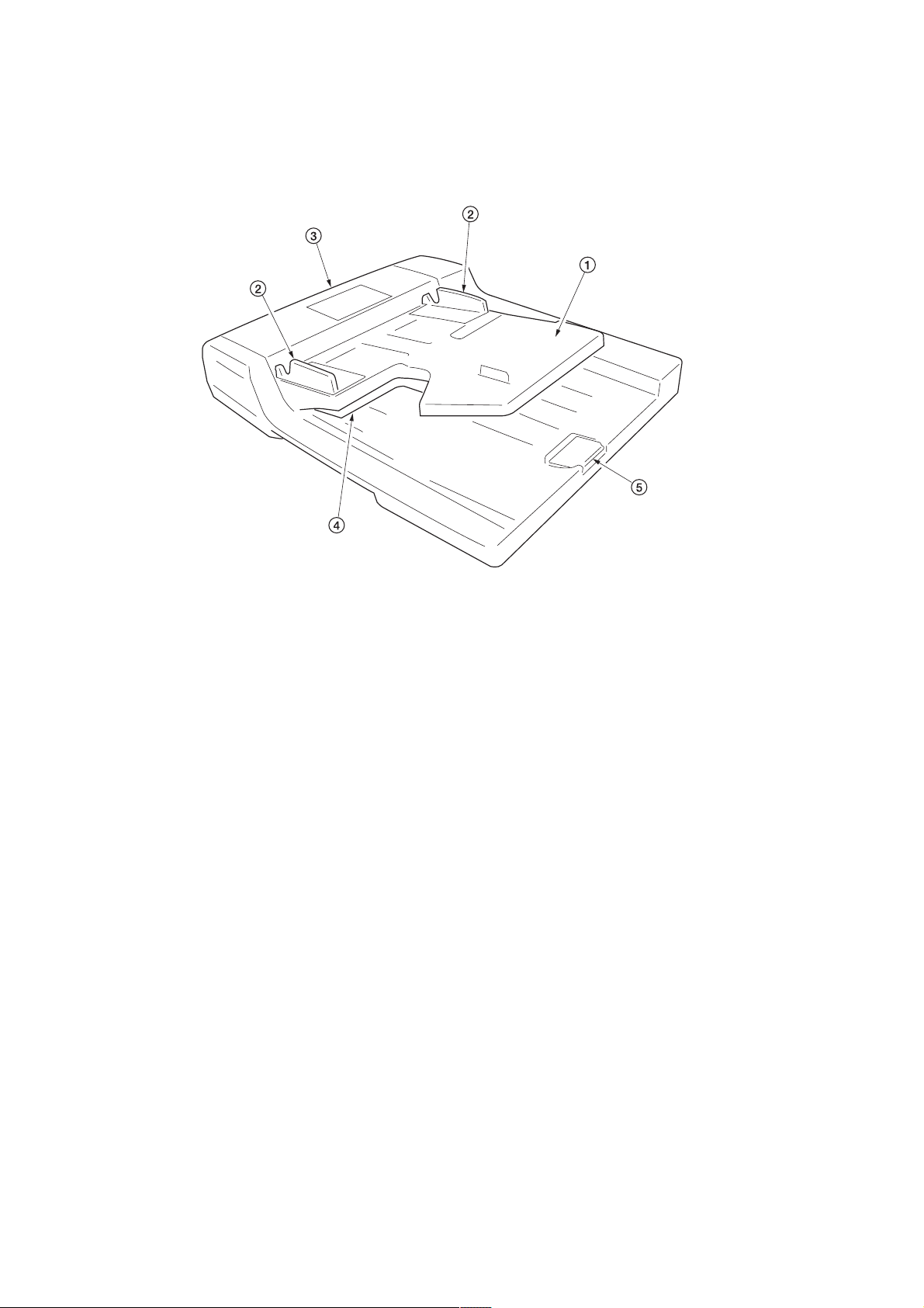
Figure 1-1-1
1 Original table
2 Original insert guides
3 DP original cover
4 Switchback tray
5 Ejection extension
1-1-2
Page 12
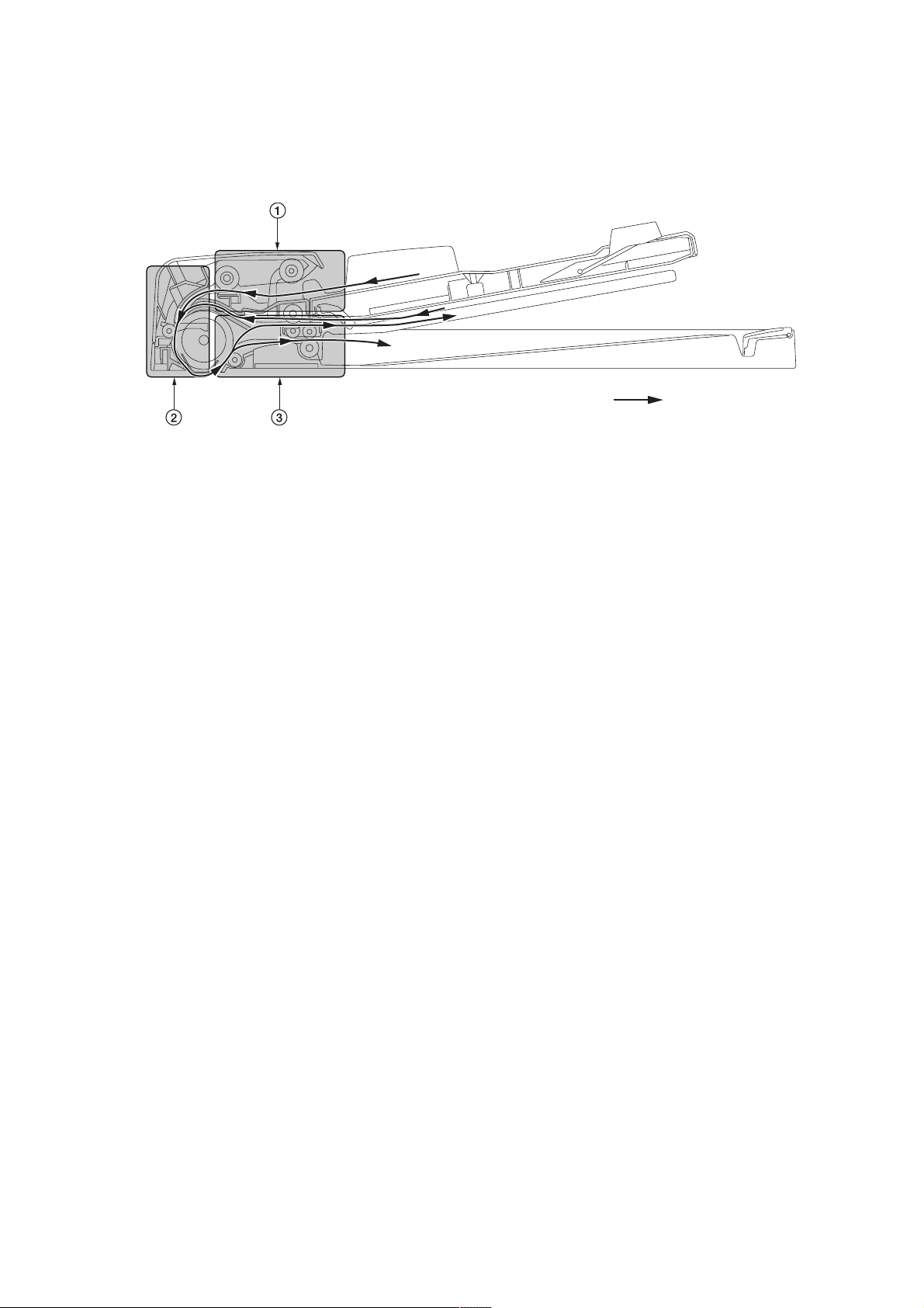
1-1-3 Machine cross section
3HL
Original path
Figure 1-1-2 Machine cross section
1 Original feed section
2 Original conveying section
3 Original switchback section
1-1-3
Page 13

3HL
1-1-4 Drive system
• Original conveying motor
• Inside front of machine • Inside rear of machine
• Original feed motor
Figure 1-1-3 Drive system
1 Original conveying motor gear
2 Gear 16
3 Idle gear 49/13
4 Gear 24/30
5 Belt 174S2M
6 Pulley
7 Conveying pulley 40
8 Exit gear 16
9 Idle gear 15
0 Idle gear 15
! Exit gear 16
@ Gear 40
# Gear 30
$ Original feed motor gear
% Gear 42/29
^ Gear 20
& Gear 30
1-1-4
Figure 1-1-4 Drive system
Page 14
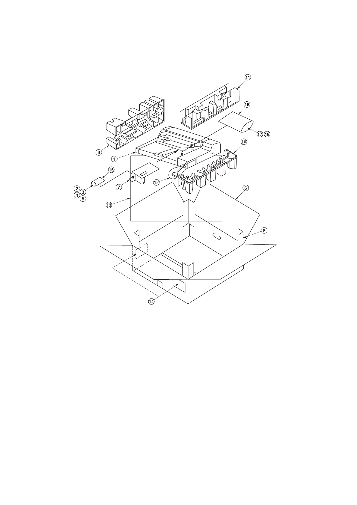
1-2-1 Unpacking and installation
(1) Unpacking
3HL
Figure 1-2-1 Unpacking
1 Document processor
2 Fixing fitting
3 Pin
4 Bronze TP screw M3x06
5 Chrome TP screw M4x10
6 Outer case
7 Spacer
8 Supports
9 Front pad
0 Rear bottom pad
! Rear upper pad
@ Air cap bag (70 × 280)
# Plastic sheet (1300 × 1300)
$ Bar code labels
% Plastic bag (70 × 110)
^ Plastic bag (240 × 350)
& Caution lavel
* Installation guide
1-2-1
Page 15
1-3-1 Maintenance mode
The copier is equipped with a maintenance function which can be used to maintain and service the machine.
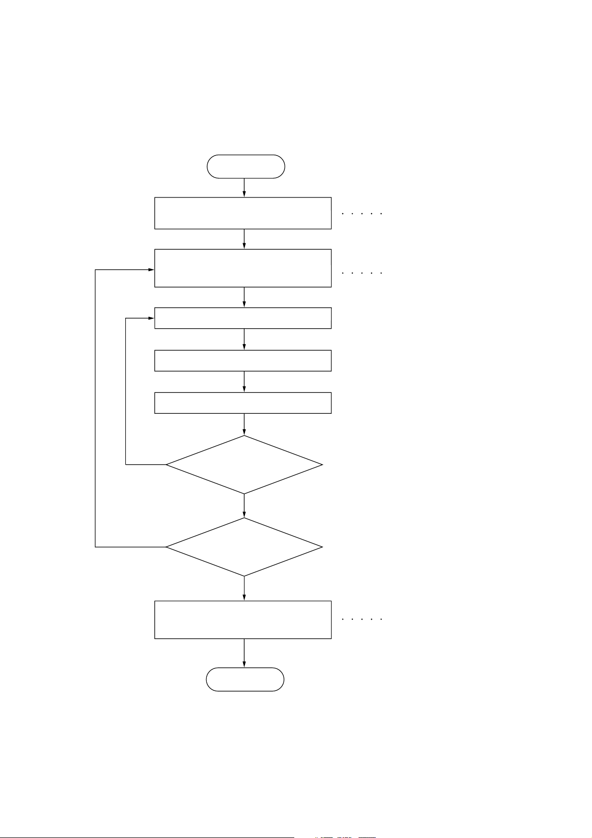
(1) Executing a maintenance item
Start
3HL
Yes
Enter “10871087” using
the numeric keys.
Enter the maintenance item
number using the zoom
+/- keys or numeric keys.
Press the start key.
The selected maintenance item is run.
Press the stop/clear key.
Repeat the same
maintenance item?
Maintenance mode is entered.
The maintenance item is
selected.
Yes
No
Run another maintenance
item?
No
Enter “001” using the
+/- keys
or numeric keys
and press the start key.
End
zoom
Maintenance mode is exited.
1-3-1
Page 16

3HL
(2) Maintenance mode item list
Section
DP U019 Displaying the ROM version —
Item
No. setting*
U068 Adjusting the scanning position for originals from the DP 0
U070 Adjusting the DP magnification 0
U071 Adjusting the DP scanning timing
• DP leading edge registration 0
• DP trailing edge registration 0
U072 Adjusting the DP center line 0
U074 Adjusting the DP input light luminosity 1
U087 Turning the DP scanning position adjust mode on/off 35
U203 Operating DP separately —
U243 Checking the operation of the DP motors and solenoids —
U244 Checking the DP switches —
U404 Adjusting margins for scanning an original from the DP —
Maintenance item contents
Initial
* Initial setting for executing maintenance item U020
1-3-2
Page 17
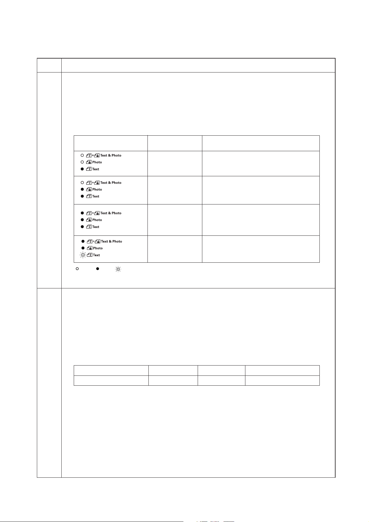
(3) Contents of maintenance mode items
3HL
Maintenance
item No.
U019 Displaying the ROM version
Description
Displays the part number of the ROM fitted to each board.
Purpose
To check the part number or to decide if the ROM version is new from the last digit of the number.
Method
1. Press the start key. A selection item appears.
2. Select the item to be displayed using the image mode selection key and copy exposure adjustment keys.
Image mode LEDs
Description
Copy exposure
indicator
Exp. 1 number of the main ROM
Exp. 2 number of the main ROM sub
Exp. 1 number of the engine ROM
Exp. 2 number of the engine ROM sub
Exp. 1 number of the first paper feeder ROM
Exp. 2 number of the second paper feeder ROM
Exp. 3 number of the third paper feeder ROM
Copy quantity display
Exp. 1 number of the DP ROM
: Off, : On, : Flashing
Completion
Press the stop/clear key. The indication for selecting a maintenance item No. appears.
U068 Adjusting the scanning position for originals from the DP
Description
Adjusts the position for scanning originals from the DP.
Purpose
Used when there is a regular error between the leading edges of the original and the copy image when the DP
is used.
Method
Press the start key.
Setting
1. Change the setting using the zoom +/– keys.
Description Setting range Initial setting Change in value per step
Scanning position –17 to +17 0 0.254 mm
Increasing the setting moves the image backward, and decreasing it moves the image forward.
2. Press the start key. The value is set.
Completion
Press the stop/clear key. The indication for selecting a maintenance item No. appears.
1-3-3
Page 18

3HL
Maintenance
item No.
U070 Adjusting the DP magnification
Adjustment
See pages 1-5-6.
U071 Adjusting the DP scanning timing
Adjustment
See page 1-5-8 and 9.
U072 Adjusting the DP center line
Adjustment
See page 1-5-7.
U074 Adjusting the DP input light luminosity
Description
Adjusts the luminosity of the exposure lamp for scanning originals from the DP.
Purpose
Used if the exposure amount differs significantly between when scanning an original on the contact glass and
when scanning an original from the DP.
Method
Press the start key.
Setting
1. Change the setting using the zoom +/– keys.
Description Setting range Initial setting
DP input light luminosity 0 to 8 1
Increasing the setting makes the luminosity higher, and decreasing it makes the luminosity lower.
2. Press the start key. The value is set.
Test copy mode
While this maintenance item is being performed, copying from an original can be made in test copy mode.
Completion
Press the stop/clear key. The indication for selecting a maintenance item No. appears.
Description
1-3-4
Page 19

3HL
Maintenance
item No.
U087 Turning the DP scanning position adjust mode on/off
Description
Turns on or off the DP scanning position adjust mode, in which the DP original scanning position is adjusted
automatically by determining the presence or absence of dust on the slit glass. Also changes the reference
data for identifying dust.
Reference
In the DP original scanning position adjust mode, the presence or absence of dust is determined by comparing
the scan data of the original trailing edge and that taken after the original is conveyed past the DP original
scanning position. If dust is identified, the DP original scanning position is adjusted for the following originals.
Purpose
Used to prevent appearance of black lines due to dust adhering in the original scanning position on the slit
glass when the DP is used.
Method
1. Press the start key.
2. Select the item to be set by lighting a copy exposure indicator using the copy exposure adjustment keys.
Copy exposure indicator Description
Exp. 1 Setting the mode on/off
Exp. 2 Setting the reference data for identifying dust
Setting the mode on/off
1. Select “on” or “oFF” using the zoom +/– keys.
Display Description
on DP scanning position adjust mode on
oFF DP scanning position adjust mode off
Initial setting: on
2. Press the start key. The setting is set.
Setting the reference data for identifying dust
Available only when the mode is turned on.
1. Change the setting using the zoom +/– keys.
Description Setting range Initial setting
Minimum density to be regarded as dust 10 to 95 35
Example
The figure indicates the density in 256 levels of gray (0: white, 255: black). When the setting is 35, data of
the level of 35 or higher is regarded as dust and data of lower level is regarded as the background (scan
data taken when there is no original).
Description
2. Press the start key. The value is set.
Completion
Press the stop/clear key while a selection item is displayed. The indication for selecting a maintenance item No.
appears.
1-3-5
Page 20

3HL
Maintenance
item No.
U203 Operating DP separately
Description
Simulates the original conveying operation separately in the DP.
Purpose
To check the DP.
Method
1. Press the start key.
2. Place an original in the DP if running this simulation with paper.
3. Select the item to be operated using the copy exposure adjustment keys.
Display (copy exposure indicator) Operation
d-P (exp. 1) With paper
d-n (exp. 2) Without paper (continuous operation)
dp2 (exp. 3) With paper (duplex mode)
dn2 (exp. 4) Without paper (duplex mode)
4. Press the start key. The operation starts.
5. To stop continuous operation, press the stop/clear key.
Completion
Press the stop/clear key when the operation stops. The indication for selecting a maintenance item No.
appears.
U243 Checking the operation of the DP motors and solenoids
Description
Turns the motors and solenoids in the DP on.
Purpose
To check the operation of the DP motors and solenoids.
Method
1. Press the start key.
2. Select the motor or solenoid to be operated using the copy exposure adjustment keys.
3. Press the start key. The operation starts.
Indication (copy exposure indicator)
F-0 (exp. 1) Original feed motor (OFM)
C-0 (exp. 2) Original conveying motor (OCM)
b-S (exp. 3) Switchback feedshift solenoid (SBFSSOL)
P-S (exp. 4) Switchback pressure solenoid (SBPSOL)
Description
Motor
1-3-6
4. To turn each motor off, press the stop/clear key.
Completion
Press the stop/clear key when operation stops. The indication for selecting a maintenance item No. appears.
Page 21

3HL
Maintenance
item No.
U244 Checking the DP switches
Description
Displays the status of the switches in the DP.
Purpose
To check if switches in the DP operate correctly.
Method
1. Press the start key. "-S-" appears.
2. Turn each switche on and off manually to check the status. When the on-status of a switch is detected, the
LEDs on the operation panel corresponding to the operated switch lights.
LEDs Switch
Auto Exp. Original set switch (OSSW)
Text & Photo DP timing switch (DPTSW)
Photo Original detection switch (ODSW)
Text DP original cover switch (DPOCSW)
Program Original size length switch (OSLSW)
Eco-copy Original switchback switch (OSBSW)
Completion
Press the stop/clear key. The indication for selecting a maintenance item No. appears.
U404 Adjusting margins for scanning an original from the DP
Adjustment
See pages 1-5-10.
Description
1-3-7
Page 22

3HL
1-4-1 Original misfeed detection
(1) Original misfeed indication
When an original jams, the copier immediately stops copying and displays the jam location on the operation panel.
To remove the jammed original in the DP, open the DP original cover.
To reset the original misfeed detection, open and close the DP original cover to turn DP original cover switch off and on.
(2) Original misfeed detection conditions
DPTSW
OFM
OCM
OSBSW
Figure 1-4-1
1-4-1
Page 23

3HL
Section Jam code Description Conditions
Original
feed section
70
No original feed
During the primary feed of the second original in the singlesided or double-sided original mode, even if retry operation is
performed five times, primary original feed is not performed.
Original
conveying
section
Original
switchback
section
71
72
73
74
75
An original jam in the
original conveying section 1
An original size error jam
An original jam in the
original conveying section 2
An original jam in the
original conveying section 3
An original jam in the
original switchback section
During the secondary original feed in the single-sided or
double-sided original mode, the DP timing switch (DPTSW)
does not turn off within 6500 ms of the original conveying
motor (OCM) turning on.
During the secondary original feed in the single-sided or
double-sided original mode, the DP timing switch (DPTSW)
does turn off within 750 ms of the original conveying motor
(OCM) turning on.
During scanning of the second side or reversing of the original for ejection in the double-sided original mode, the DP timing switch (DPTSW) does not turn off within 6500 ms of the
original conveying motor (OCM) turning on.
During scanning of the second side or reversing of the original for ejection in the double-sided original mode, the DP timing switch (DPTSW) does not turn on within 750 ms of the
original conveying motor (OCM) turning on.
During the switchback operation of an original in the doublesided original mode, the original switchback switch (OSBSW)
does not turn on within 1300 ms of the original conveying
motor (OCM) turning on.
1-4-2
Page 24

(3) Original misfeeds
Problem Causes/check procedures Corrective measures
(1)
An original jams
when the power
switch is turned on.
A piece of paper torn from
an original is caught
around the DP timing
switch or original
switchback switch.
Check visually and remove it, if any.
3HL
(2)
An original jams in
the original feed
section is indicated
during copying (no
original feed).
Jam code 70
(3)
An original jams in
the original conveying section is indicated during copying (An original jam
in the original conveying section 1).
Jam code 71
Defective DP timing
switch.
Defective original
switchback switch.
Defective original set
switch.
Check if the original feed
motor malfunctions.
Check if the DP paper
feed pulley or DP separation pad is deformed.
Broken DP timing switch
actuator.
Defective DP timing
switch.
Check if the original conveying motor malfunctions.
Run maintenance item U244 and turn DP timing switch on and
off manually. Replace DP timing switch if indication of the corresponding switch is not light.
Run maintenance item U244 and turn original switchback switch
on and off manually. Replace original switchback switch if indication of the corresponding switch is not light.
Run maintenance item U244 and turn original set switch on and
off manually. Replace original set switch if indication of the corresponding switch is not light.
Run maintenance item U243 and select the original feed motor
to be turned on and off. Check the status and remedy if necessary.
Check visually and replace the deformed pulley.
Check visually and replace DP timing switch if its actuator is broken.
Run maintenance item U244 and turn DP timing switch on and
off manually. Replace DP timing switch if indication of the corresponding switch is not light.
Run maintenance item U243 and select the original conveying
motor to be turned on and off. Check the status and remedy if
necessary.
(4)
An original jams in
the original conveying section is indicated during copying (An original size
error jam).
Jam code 72
(5)
An original jams in
the original conveying section is indicated during copying (An original jam
in the original conveying section 2).
Jam code 73
Broken DP timing switch
actuator.
Defective DP timing
switch.
Check if the original conveying motor malfunctions.
Broken DP timing switch
actuator.
Defective DP timing
switch.
Check if the original conveying motor malfunctions.
Check if the switchback
feedshift solenoid malfunctions.
Check visually and replace DP timing switch if its actuator is broken.
Run maintenance item U244 and turn DP timing switch on and
off manually. Replace DP timing switch if indication of the corresponding switch is not light.
Run maintenance item U243 and select the original conveying
motor to be turned on and off. Check the status and remedy if
necessary.
Run maintenance item U243 and select the switchback feedshift
solenoid to be turned on and off. Check the status and remedy if
necessary.
1-4-3
Page 25

3HL
Problem Causes/check procedures Corrective measures
(6)
An original jams in
the original conveying section is indicated during copying (An original jam
in the original conveying section 3).
Jam code 74
Broken DP timing switch
actuator.
Defective DP timing
switch.
Check if the original conveying motor malfunctions.
Check visually and replace DP timing switch if its actuator is broken.
Run maintenance item U244 and turn DP timing switch on and
off manually. Replace DP timing switch if indication of the corresponding switch is not light.
Run maintenance item U243 and select the original conveying
motor to be turned on and off. Check the status and remedy if
necessary.
(7)
An original jams in
the original
switchback section
is indicated during
copying (An original
jam in the original
switchback section).
Jam code 75
(8)
Original jams frequently.
Check if the switchback
feedshift solenoid malfunctions.
Defective original
switchback switch.
Check if the original conveying motor malfunctions.
Check if the switchback
feedshift solenoid malfunctions.
An original outside the
specifications is used.
The DP forwarding pulley
or DP paper feed pulley is
dirty with paper powder.
The DP paper feed pulley
and DP separation pad do
not contact correctly.
Run maintenance item U243 and select the switchback feedshift
solenoid to be turned on and off. Check the status and remedy if
necessary.
Run maintenance item U244 and turn original switchback switch
on and off manually. Replace original switchback switch if indication of the corresponding switch is not light.
Run maintenance item U243 and select the original conveying
motor to be turned on and off. Check the status and remedy if
necessary.
Run maintenance item U243 and select the switchback feedshift
solenoid to be turned on and off. Check the status and remedy if
necessary.
Use only originals conforming to the specifications.
Clean with isopropyl alcohol.
Check and remedy.
1-4-4
Page 26

1-4-2 Self-diagnosis
(1) Self-diagnostic function
When a problem is detected, copying is disabled. "C" and a number 041 altenates.
After removing the problem, the self-diagnostic function can be reset by turning safety switch off and back on.
(2) Self diagnostic codes
3HL
Code Contents
C041
(A041*)
Optional DP communication problem
• Communication fails five times successively.
Remarks
Causes Check procedures/corrective measures
DP installed incorrectly.
Defective main
PCB or DP driver
PCB.
Check the installation state of the DP and
adjust it if it is not properly installed.
Replace the main PCB or DP driver PCB
and check for correct operation.
“A” is displayed on the operation panel.
1-4-5
Page 27

3HL
1-4-3 Image formation problems
(1) There is a regular error
between the centers of
the original and copy
image.
See page 1-4-7
(2) There is a regular error
between the leading
edges of the original
and copy image.
See page 1-4-7
1-4-6
Page 28

3HL
(1) There is a regular
error between the
centers of the
original and copy
image.
Causes
1. Misadjusted DP center line.
(2) There is a regular
error between the
leading edges of
the original and
copy image.
Causes
1. Misadjusted DP center line.
Check procedures/corrective measures
Readjust the DP center line (see page 1-5-7).
Causes
1. Misadjusted DP original scanning start
position.
Causes
1. Misadjusted DP original scanning start
position.
Check procedures/corrective measures
Readjust the DP original scanning start position (see page 1-5-8).
1-4-7
Page 29

3HL
1-4-4 Electrical problems
Problem Causes Check procedures/corrective measures
(1)
The machine does
not operate when
the power switch is
turned on.
The DP original cover is
not closed completely.
Defective DP original
cover switch.
Check the DP original cover.
Check for continuity across the contacts of switch. If none, replace the switch.
(2)
The original feed
motor does not
operate.
(3)
The original conveying motor does not
operate.
(4)
The switchback
feedshift solenoid
does not operate.
Poor contact in the original
feed motor connector terminals.
Broken original feed motor
gear.
Defective original feed motor.
Defective DP driver PCB.
Poor contact in the original
conveying motor connector terminals.
Broken original conveying
motor gear.
Defective original conveying motor.
Defective DP driver PCB.
Defective switchback
feedshift solenoid coil.
Poor contact in the switchback feedshift solenoid
connector terminals.
Reinsert the connector. Also check for continuity within the connector cable. If none, remedy or replace the cable.
Check visually and replace the original feed motor if necessary.
Run maintenance item U243 and check if the original feed motor
operates when YC8-3,4,5,6 on the DP driver PCB goes low. If
not, replace the original feed motor.
Run maintenance item U243 and check if YC8-3,4,5,6 on the DP
driver PCB goes low. If not, replace the DP driver PCB.
Reinsert the connector. Also check for continuity within the connector cable. If none, remedy or replace the cable.
Check visually and replace the original conveying motor if necessary.
Run maintenance item U243 and check if the original conveying
motor operates when YC8-9,10,11,12 on the DP driver PCB
goes low. If not, replace the original conveying motor.
Run maintenance item U243 and check if YC8-9,10,11,12 on the
DP driver PCB goes low. If not, replace the DP driver PCB.
Check for continuity across the coil. If none, replace the
switchback feedshift solenoid.
Reinsert the connector. Also check for continuity within the connector cable. If none, remedy or replace the cable.
(5)
The switchback
pressure solenoid
does not operate.
(6)
The original size is
not detected correctly.
1-4-8
Defective DP driver PCB.
Defective switchback pressure solenoid coil.
Poor contact in the switchback pressure solenoid
connector terminals.
Defective DP driver PCB.
Poor contact in the original
size length switch connector terminals.
Defective original size
length switch.
Run maintenance item U243 and check if YC7-5 on the DP
driver PCB goes low. If not, replace the DP driver PCB.
Check for continuity across the coil. If none, replace the
switchback pressure solenoid.
Reinsert the connector. Also check for continuity within the connector cable. If none, remedy or replace the cable.
Run maintenance item U243 and check if YC7-2,3 on the DP
driver PCB goes low. If not, replace the DP driver PCB.
Reinsert the connector. Also check for continuity within the connector cable. If none, remedy or replace the cable.
Check if YC2-4 on the DP driver PCB goes low when the original
size length switch is turned on. If not, replace the original size
length switch.
Page 30

Problem Causes Check procedures/corrective measures
(6)
The original size is
not detected correctly.
Poor contact in the original
size width switch connector terminals.
Defective original size
width switch.
Reinsert the connector. Also check for continuity within the connector cable. If none, remedy or replace the cable.
Check if YC2-2 on the DP driver PCB goes low when the original
size width switch is turned on. If not, replace the original size
width switch.
3HL
(7)
A original jam in the
DP is indicated
when the power
switch is turned on.
(8)
The message requesting cover to be
closed is displayed
when the DP original cover is closed.
(9)
Others.
A piece of paper torn from
copy paper is caught
around DP timing switch or
original switchback switch.
Defective DP timing
switch.
Defective original
switchback switch.
Poor contact in the DP
original cover switch connector terminals.
Defective DP original
cover switch.
Wiring is broken, shorted
or makes poor contact.
Noise.
Check and remove if any.
Run maintenance item U244 and turn DP timing switch on and
off manually. Replace DP timing switch if indication of the corresponding sensor is not light.
Run maintenance item U244 and turn original switchback switch
on and off manually. Replace original switchback switch if indication of the corresponding sensor is not light.
Reinsert the connector. Also check for continuity within the connector cable. If none, remedy or replace the cable.
Run maintenance item U244 and turn DP original cover switch
on and off manually. Replace DP original cover switch if indication of the corresponding sensor is not light.
Check for continuity. If none, repair.
Locate the source of noise and remove.
1-4-9
Page 31

3HL
1-4-5 Mechanical problems
Problem Causes/check procedures Corrective measures
(1)
No primary original
feed.
Check if the surfaces of the following pulleys
are dirty with paper powder: DP forwarding
pulley, DP paper feed pulley and DP separation pad.
Clean with isopropyl alcohol.
(2)
Multiple sheets of original are fed at one time.
(3)
Originals jam.
(4)
Abnormal noise is
heard.
Check if the DP forwarding pulley, DP paper
feed pulley or DP separation pad is deformed.
Check if the DP separation pad is worn.
Deformed guides along the paper conveying
path.
Check if the contact between the conveying
roller and pulley is correct.
Check if the contact between the exit roller
and pulley is correct.
Check if the contact between the switchback
roller and pulley is correct.
Check if the pulleys, rollers and gears operate smoothly.
Check visually and replace any deformed
pulleys (see page 1-5-3 and 5).
Replace the DP separation pad if it is worn
(see page 1-5-5).
Repair or replace if necessary.
Check visually and remedy if necessary.
Check visually and remedy if necessary.
Check visually and remedy if necessary.
Grease the bearings and gears.
1-4-10
Page 32

1-5-1 Precautions for assembly and disassembly
(1) Precautions
• Be sure to turn the power switch off and disconnect the power plug before starting disassembly.
• When handling PCBs, do not touch connectors with bare hands or damage the board.
• Do not touch any PCB containing ICs with bare hands or any object prone to static charge.
• Use the following testers when measuring voltages:
Hioki 3200
Sanwa MD-180C
Sanwa YX-360TR
Beckman TECH300
Beckman DM45
Beckman 330*
Beckman 3030*
Beckman DM850*
Fluke 8060A*
Arlec DMM1050
Arlec YF1030C
* Capable of measuring RMS values.
3HL
1-5-1
Page 33

3HL
(2) Running a maintenance item
Start
Yes
Enter “10871087” using
the numeric keys.
Enter the maintenance item
number using the zoom
+/- keys or numeric keys.
Press the start key.
The selected maintenance item is run.
Press the stop/clear key.
Repeat the same
maintenance item?
Maintenance mode is entered.
The maintenance item is
selected.
Yes
No
Run another maintenance
item?
No
Enter “001” using the
or numeric keys
+/- keys
and press the start key.
End
zoom
Maintenance mode is exited.
1-5-2
Page 34

1-5-2 DP
(1) Detaching and refitting the DP forwarding pulley and DP paper feed pulley
Follow the procedure below to clean or replace the DP forwarding pulley or DP paper feed pulley.
Procedure
• Detaching the DP forwarding pulley
1. Open the DP original cover.
2. Raise the DP paper feed pulley unit and pull
the hooking portion for the DP forwarding
pulley shaft toward the front side to remove
the DP forwarding pulley shaft.
3. Remove the DP forwarding pulley.
DP paper feed pulley unit
DP forwarding
pulley shaft
3HL
• Detaching the DP paper feed pulley
4. Remove the stop ring and paper feed guide
at front side of the DP paper feed pulley
shaft.
* When mounting the paper feed guide, fit the
projection of the paper feed guide into the
groove of the DP paper feed pulley shaft.
5. Remove the DP paper feed pulley unit from
DP.
DP forwarding pulley
Figure 1-5-1
Groove
Projection
Stop ring
DP paper
feed pulley
shaft
Figure 1-5-2
Paper feed
guide
1-5-3
Page 35

3HL
6. Remove the two stop rings and then remove
the DP paper feed pulley shaft from the DP
paper feed pulley unit.
7. Remove the DP paper feed pulley from the
DP paper feed pulley shaft.
8. Clean or replace the DP forwarding pulley
and the DP paper feed pulley and refit all the
removed parts.
Stop ring
DP paper feed pullry
Stop ring
DP paper feed
pullry shaft
Figure 1-5-3
1-5-4
Page 36

(2) Detaching and refitting the DP separation pad
Follow the procedure below to clean or replace the DP separation pad.
Procedure
1. Remove the DP paper feed pulley unit (see
page 1-5-3).
2. Push the fitting portions of the DP separation
pad. Remove the DP separation pad.
3. Clean or replace the DP separation pad and
refit all the removed parts.
Fitting portion
3HL
DP separation pad
Fitting portion
Figure 1-5-4
1-5-5
Page 37

3HL
(3) Adjusting the DP magnification
Adjust magnification in the auxiliary scanning direction if magnification is incorrect when the DP is used.
U053
(See the service manual
of the copier.)
U065(auxiliary scanning
direction)
(See the service manual
of the copier.)
U070
Caution
Before making the following adjustment, ensure that the above adjustments have been made in maintenance mode.
Procedure
Main scanning
direction
Start
Auxiliary
Enter maintenance mode.
Enter “070” using the numeric keys.
Press the start key.
scanning
direction
Original
Copy
example 1
Figure 1-5-5
Copy
example 2
Press the interrupt key.
Place an original on the DP
and make a test copy.
Is the image correct?
Yes
Press the stop/clear key to
exit maintenance mode.
End
Press the start key.
The new setting
is stored.
For copy example 1, increase
the value using the zoom (+) key.
No
For copy example 2, decrease
the value using the zoom (–) key.
Setting range: –25 – +25
Initial setting: 0
Changing the value by 1 changes
the magnification by 0.1%.
Increasing the value makes
the image longer, and decreasing it
make the image shorter.
1-5-6
Page 38

3HL
(4) Adjusting the DP center line
Perform the following adjustment if there is a regular error between the centers of the original and the copy image when
the DP is used.
U034
(See the service manual
of the copier.)
(See the service manual
U067
U072
of the copier.)
Caution
Before making the following adjustment, ensure that the above adjustments have been made in maintenance mode.
Procedure
Reference
Start
Enter maintenance mode.
Copy
example 2
Enter “072” using the numeric keys.
Original Copy
example 1
Figure 1-5-6
Press the start key.
Press the interrupt key.
Place an original on the DP
and make a test copy.
Press the start key.
The new setting
is stored.
Is the image correct?
Yes
Press the stop/clear key to
exit maintenance mode.
End
For copy example 1, decrease
No
the value using the zoom (–) key.
For copy example 2, increase
the value using the the zoom (+) key.
Setting range: –6.6 – +6.6
Initial setting: 0
Changing the value by 1 moves
the center line by 0.1 mm.
Increasing the setting moves image
to the left, and decreasing it moves
the image to the right.
1-5-7
Page 39

3HL
(5) Adjusting the DP scanning timing
Perform the following adjustment if there is a regular error between the leading or trailing edges of the original and the
copy image.
U034
(See the service manual
of the copier.)
(See the service manual
U066
U071
of the copier.)
Caution
Before making the following adjustment, ensure that the above adjustments have been made in maintenance mode.
(5-1) Adjusting the DP leading edge registration
Procedure
Start
Enter maintenance mode.
Enter “071” using the numeric keys.
Press the start key.
Original
Copy
example 1
Copy
example 2
Figure 1-5-7
Select “exp. 1”.
Press the interrupt key.
Place an original on the DP
and make a test copy.
Is the image correct?
Yes
Press the stop/clear key to
exit maintenance mode.
End
Press the start key.
The new setting
is stored.
For copy example 1, decrease
No
the value using the zoom (–) key.
For copy example 2, increase
the value using the zoom (+) key.
Setting range: –32 – +32
Initial setting: 0
Changing the value by 1 moves
the leading edge by 0.254 mm.
Increasing forward and decreasing it moves
the image backward.
1-5-8
Page 40

(5-2) Adjusting the DP trailing edge registration
Procedure
Start
Enter maintenance mode.
3HL
Enter “071” using the numeric keys.
Press the start key.
Select “exp. 2”.
Press the interrupt key.
Place an original on the DP
and make a test copy.
Is the image correct?
Yes
Press the stop/clear key to
exit maintenance mode.
End
Original Copy
Figure 1-5-8
Press the start key.
The new setting
is stored.
For copy example 1, decrease
No
the value using the zoom (–) key.
For copy example 2, increase
the value using the zoom (+) key.
Setting range: –42 – +32
initial setting: 0
Changing the value by 1 moves
the trailing edge by 0.254 mm.
Increasing forward and decreasing it moves
the image backward.
example 1
Copy
example 2
1-5-9
Page 41

3HL
(6) Adjusting the margins for scanning the original from the DP
Perform the following adjustment if margins are not correct.
(See the service manual
U402
of the copier.)
(See the service manual
U403
U404
of the copier.)
Caution
Before making the following adjustment, ensure that the above adjustments have been made in maintenance mode.
Procedure
DP leading edge margin (3 ± 2.5 mm)
Ejection direction
(reference)
Start
Enter maintenance mode.
Enter “404” using the numeric keys.
DP left margin
+1.5
(2.5 mm)
–2.0
DP right margin
(2.5 mm)
DP trailing edge margin
(3 ± 2.5 mm)
+1.5
–2.0
Figure 1-5-9
Press the start key.
Select the item to be adjusted.
Press the interrupt key.
Place an original on the DP
and make a test copy.
(A test copy is output at the
reduction ratio of 95%).
Are the margins correct?
Yes
Proceed to another mode?
Press the stop/clear key to
exit maintenance mode.
Yes
No
No
Exp. 1 (lit): DP left margin
Exp. 2 (lit): DP leading edge margin
Exp. 3 (lit): DP right margin
Exp. 4 (lit): DP trailing edge margin
Press the start key.
The new setting
is stored.
Change the setting.
Increasing the value using the zoom
(+) key makes the margin wider.
Decreasing the value using the
zoom (–) key makes the margin
narrower.
Setting range (initial setting)
DP left margin: 0 – +10.0 (2.0)
DP leading edge margin: 0 – +10.0 (3.0)
DP right margin: 0 – +10.0 (2.0)
DP trailing edge margin: 0 – +10.0 (2.0)
Changing the value by one moves
the margin by 0.5 mm for all.
1-5-10
End
Page 42

3HL
2-1-1 Mechanical construction
The DP consists of the original feed section, original conveying section and original switchback section.
The original feed section conveys an original set on the original table to the original conveying section in synchronization
with original scanning of the scanner on the copier.
The original conveying section conveys an original onto the slit glass and ejects it after scanning is complete.
The original switchback section reverses an original conveyed from the original conveying section and conveys it again
to the original conveying section in the double-sided original mode.
1 DP forwarding pulley
2 DP paper feed pulley
3 DP separation pad
4 Conveying pulley
5 Conveying roller
6 Conveying pulley
7 Switchback feedshift guide
8 Switchback roller
Figure 2-1-1
9 Switchback pulley
0 Exit pulley
! Exit roller
@ Original set switch (OSSW)
# DP timing switch (DPTSW)
$ Original switchback switch
(OSBSW)
2-1-1
Page 43

3HL
OCM OFM
OSBSW
OFM
OCM
DPTSW
DPTSW
YC4-2
Paper feed start
request signal
SBFSSOL
OCM A,B,_A,_B
YC8-6
YC8-3-
SBFSSOL
YC7-5
DPDPCB
Figure 2-1-2 Block diagram
Scanning start
request signal
100 pls 214 pls
7400 pls
SBPSOL
OFM A,B,_A,_B
YC8-9-
YC8-12
SBPSOL
YC7-2,3
4000 pls
OSBSW
YC2-7
214 pls
980 pls
DPTSW
OVSYNC
740 pls
Timing chart 2-1-1 Original feed (A3, single-sided original mode)
a When the paper feed start request signal is input from the copier, the original feed motor (OFM) turns on and an
original is fed.
b 100 pulses after the DP timing switch (DPTSW) turns on, the original feed motor (OFM) turns off and original
conveying motor (OCM) turns on.
c 7400 pulses after the original conveying motor (OCM) turns on, the original feed motor (OFM) turns on.
d 214 pulses after the original feed motor (OFM) turns on, the original feed motor (OFM) turns off.
e 4000 pulses after the DP timing switch (DPTSW) turns off, the original conveying motor (OCM) turns off.
2-1-2
Page 44

3HL
(1) Operation of original switchback
In the double-sided original mode, after the first side of an original is scanned, the switchback feedshift guide is activated
to switch the conveying path to the switchback tray side and the original is fed to the switchback tray. Then, the original is
reversed by the reverse rotation of the original conveying motor (OCM) and conveyed again to the original conveying
section. After the second side is scanned, the original is fed temporarily to the switchback tray, is reversed, is conveyed
without scanning, and then is ejected to the exit tray. Also the switchback press solenoid (SBPSOL) is activated to
release the switchback pulley for preventing original jams in the original switchback section.
• First side scanning→Switchback tray
Original conveying motor (OCM): forwerd rotation
Switchback feedshift solenoid (SBFSSOL): ON
• Original switchback operate
Original conveying motor (OCM): reverse rotation
Switchback feedshift solenoid (SBFSSOL): OFF
• Second side scanning→Switchback tray
Original conveying motor (OCM): forwerd rotation
Switchback feedshift solenoid (SBFSSOL): ON
• Original switchback operate
Original conveying motor (OCM): reverse rotation
Switchback feedshift solenoid (SBFSSOL): OFF
• Conveyed without scanning→Exit tray
Original conveying motor (OCM): forwerd rotation
Switchback feedshift solenoid (SBFSSOL): OFF
Figure 2-1-3 Operation of original switchback
2-1-3
Page 45

3HL
OFM
OCM
DPTSW
OSBSW
SBFSSOL
SBPSOL
Paper feed start
request signal
100 pls
2840 pls
980 pls
214 pls
2600 pls
740 pls
100 ms
Scanning start
request signal
100 ms
150 pls
100 pls
980 pls
2600 pls
740 pls
100 ms
150 pls
100 ms
50 pls
OVSYNC
Timing chart 2-1-2 Original feed (A4, double-sided original mode)
a When the paper feed start request signal is input from the copier, the original feed motor (OFM) turns on and an
original is fed.
b 100 pulses after the DP timing switch (DPTSW) turns on, the original feed motor (OFM) turns off and original
conveying motor (OCM) rotates forward.
c 980 pulses after the original conveying motor (OCM) turns on, the switchback feedshift solenoid (SBFSSOL) turns on.
d 2840 pulses after the original conveying motor (OCM) turns on, the original feed motor (OFM) turns on for 214
pulses.
e 2600 pulses after the DP timing switch (DPTSW) turns on, the original feed motor (OFM) and switchback feedshift
solenoid (SBFSSOL) turns off.
f 100 pulses after the original conveying motor (OCM) turns off, the original conveying motor (OCM) rotates reverse.
g 150 pulses after the DP timing switch (DPTSW) turns on, the original conveying motor (OCM) turns off, and 100 ms
later, the motor turns on (forward).
h 100 pulses after the original conveying motor (OCM) turns on, the switchback feedshift solenoid (SBFSSOL) and
switchback pressure (SBPSOL) turns on.
i The DP timing switch (DPTSW) turns off at the same time, the switchback pressure (SBPSOL) turns off.
j 2600 pulses after the DP timing switch (DPTSW) turns off, the original conveying motor (OCM) and switchback
feedshift solenoid (SBFSSOL) turns off.
k 100 pulses after the original conveying motor (OCM) turns off, the original conveying motor (OCM) rotates reverse.
l 150 pulses after the DP timing switch (DPTSW) turns on, the original conveying motor (OCM) turns off, and 100 ms
later, the motor turns on (forward).
2-1-4
Page 46

2-2-1 Electrical parts layout
(1) PCBs
3HL
1
Machine front
Machine inside
Machine rear
Figure 2-2-1 PCBs
1. DP driver PCB (DPDPCB) ........................... Controls electrical components of the DP.
2-2-1
Page 47

3HL
(2) Switches and sensors
6
1
2
3
4
Machine front
5
Machine inside
7
Machine rear
Figure 2-2-2 Switches and sensors
1. DP original cover switch (DPOCSW) ........... Breaks the safety circuit when the DP original cover is opened; resets
original misfeed detection.
2. Original set switch (OSSW) ......................... Detects the presence of an original.
3. DP timing switch (DPTSW) .......................... Detects the original scanning timing.
4. Original switchback switch (OSBSW) .......... Detects an original misfeed in the original switchback section.
5. Original size width switch (OSWSW) ........... Detects the width of the original.
6. Original size length switch (OSLSW) ........... Detects the length of the original.
7. DP open/close switch (OPOCSW) ............... Detects the opening/closing of the DP.
2-2-2
Page 48

(3) Motors and solenoids
1
3
3HL
2
4
Machine front
Machine inside
Machine rear
Figure 2-2-3 Motors and solenoids
1. Original feed motor (OFM) ........................... Drives the original feed section.
2. Original conveying motor (OCM) ................. Drives the original conveying and switchback sections.
3. Switchback feedshift solenoid
(SBFSSOL) .................................................. Operates the switchback feedshift guide.
4. Switchback pressure solenoid (SBPSOL) ... Operates the switchback pulley.
2-2-3
Page 49

2-3-1 DP driver PCB
DPDPCB
OSSW
3HL
OSSW
Copier
DPOCSW
ORGVSYNC
DPRDY
DPSEL
SCLK
SDO
SDI
24V
5V
DPOCSW
CPU
U1
DPOCSW
Motor
Driver
DPTSW
OSBSW
OSLSW
OSWSW
SBFSSOL
SBPSOL (RET)
SBPSOL (ACT)
OFM A,B,_A,_B
DPTSW
OSBSW
OSLSW
OSWSW
SBFSSOL
SBPSOL
OFM
OCM A,B,_A,_B
OCM
FG
Motor
Driver
Figure 2-3-1 DP driver PCB block diagram
The DP driver PCB (DPDPCB) is controlled by the engine PCB (EPCB) in the copier, and the engine PCB (EPCB) uses
serial communication to control input and output of each motor, solenoid, and switch of the DP through the CPU (U1)
equipped with a function of bidirectional serial/parallel conversion of 8-bit data.
2-3-1
Page 50

3HL
YC8
12 1
27
26
2
1
U3
1
2
14
YC6
1
YC5
3
X1
YC7
51
26
27
U2
16
YC1
1
YC4
1
8
13
YC2
PH1
E
YC3
71
A
K
Figure 2-3-2 DP driver PCB silk-screen diagram
2-3-2
Page 51

Connector Pin No. Signal I/O Description
YC1
Connected
to the
copier
1 FG - Ground
2 24 V I 24 V DC power supply from copier
3 24 V I 24 V DC power supply from copier
4 P.GND - Ground
5 P.GND - Ground
6 SRESETN I Reset signal from copier
7 ORGVSYNC O DP original scanning interval signal
8 DPRDY O DP READY signal
9 DPSEL I DP SEL signal
10 DPCLK I DP clock signal
11 SDI I DP serial communication reception
12 SDO O DP serial communication transmission
13 FG - Ground
14 FG - Ground
15 S.GND - Ground
16 5 V I 5 V DC power supply from copier
3HL
YC2
Connected
to the
original size
width
switch,
original size
length
switch and
original
switchback
switch
YC4
Connected
to the DP
timing
switch
YC5
Connected
to the
original set
switch
YC6
Connected
to the DP
original
cover swich
1 5 V O 5 V DC power supply for OSWSW
2 OSWSW I OSWSW on/off
3 S.GND - Ground
4 OSLSW I OSLSW on/off
5 5 V O 5 V DC power supply for OSLSW
6 5 V O 5 V DC power supply for OSBSW
7 OSBSW I OSBSW on/off
8 S.GND - Ground
1 5 V O 5 V DC power supply for DPTSW
2 DPTSW I DPTSW on/off
3 S.GND - Ground
1 5 V O 5 V DC power supply for OSSW
2 OSSW I OSSW on/off
3 S.GND - Ground
1 24 V O 24 V DC power supply for DPOCSW
2 Reserve - Not used
3 Reserve - Not used
4 24 V I 24 V DC power supply
YC7
Connected
to the
switchback
pressure
solenoid
and
switchback
feedshift
solenoid
1 24 V O 24 V DC power supply for SBPSOL
2 SBPSOL (ACT) O SBPSOL (ACT) on/off
3 SBPSOL (RET) O SBPSOL (RET) on/off
4 24 V O 24 V DC power supply for SBFSSOL
5 SBFSSOL O SBFSSOL on/off
2-3-3
Page 52

3HL
Connector Pin No. Signal I/O Description
YC8
Connected
to the
original
feed motor
and original
conveying
motor
1 OFM 24 V O 24 V DC power supply for OFM
2 OFM 24 V O 24 V DC power supply for OFM
3 OFM A O OFM control signal (A)
4 OFM B O OFM control signal (B)
5 OFM _A O OFM control signal (_A)
6 OFM _B O OFM control signal (_B)
7 OCM 24 V O 24 V DC power supply for OCM
8 OCM 24 V O 24 V DC power supply for OCM
9 OCM A O OCM control signal (A)
10 OCM B O OCM control signal (B)
11 OCM _A O OCM control signal (_A)
12 OCM _B O OCM control signal (_B)
2-3-4
Page 53

Maintenance parts list
Maintenance part name
Name used in service manual Name used in parts list
DP forwarding pulley PULLEY, LEADING FEED ADF 36211110 3 47
DP paper feed pulley PULLEY, PAPER FEED 3BR07040 3 44
DP separation pad PAD, SEPARATION 3HL07100 3 11
Friction plate FRICTION PLATE, CASSETTE 2A107060 3 36
Conveying roller CONVEYING ROLLER, ASS’Y 3HL00010 4 1
Conveying pulley PULLEY CONVEYING 3HL08080 3,4 32,8
Reading guide GUIDE READING 3HL08040 2 19
Switchback roller ROLLER LOOP 3HL10030 4 15
Switchback pulley PULLEY LOOP 3HL10140 4 25
Exit roller ROLLER EJECT 3HL10100 4 21
Exit pulley PULLEY CONVEYING 3HL08080 4 8
Original holder mat MAT, ORIGINAL HOLDER 2A612810 1 14
Part No. Fig. No. Ref. No.
3HL
2-4-1
Page 54

3HL
Periodic maintenance procedures
Section
Test copy and Perform at the maximum Test copy Every service
test print copy size
Section
Original feed DP forwarding pulley Replace or clean Every 100,000 counts Clean with alcohol when visiting 1-5-3
section the user.
Section
Original Conveying roller Clean Every service Clean with alcohol or a dry cloth.
conveying Conveying pulley Check or clean Every service Clean with alcohol or a dry cloth
section if it is dirty.
Maintenance
part/location
Maintenance
part/location
DP paper feed pulley Replace or clean Every 100,000 counts Clean with alcohol when visiting 1-5-3
DP separation pad Replace or clean Every 100,000 counts Clean with alcohol when visiting 1-5-5
Friction plate Clean Every service Clean with alcohol when visiting
Maintenance
part/location
Reading guide Clean Every service Clean with alcohol or a dry cloth.
Method Maintenance cycle Points and cautions Page
Method Maintenance cycle Points and cautions Page
the user.
the user.
the user.
Method Maintenance cycle Points and cautions Page
Section
Original Switchback roller Clean Every service Clean with alcohol or a dry cloth.
Switchback Switchback pulley Check or clean Every service Clean with alcohol or a dry cloth
section if it is dirty.
Section
Other Original holder mat Clean Every service Clean with alcohol or a dry cloth.
Maintenance
part/location
Exit roller Clean Every service Clean with alcohol or a dry cloth
Exit pulley Check or clean Every service Clean with alcohol or a dry cloth
Maintenance
part/location
Method Maintenance cycle Points and cautions Page
if it is dirty.
Method Maintenance cycle Points and cautions Page
2-4-2
Page 55

3HL
OFM
OCM
DPTSW
OSBSW
SBFSSOL
SBPSOL
OVSYNC
YC8-3,4,5,6
YC8-9,10,
11,12
YC4-2
YC2-7
YC7-5
YC7-2,3
YC1-1
100 pls
214 pls
214 pls
7400 pls
4000 pls
740 pls980 pls
Paper feed start
request signal
Scanning start
request signal
××
××
× 17", 1 sheet, single-sided mode
Timing chart No. 1 Original size A3/11"
2-4-3
Page 56

 Loading...