

Page 1

SERVICE
MANUAL
Published in Mar.’01
842BV110
Page 2

CAUTION
Danger of explosion if battery is incorrectly replaced. Replace only with the same or equivalent
type recommended by the manufacturer. Dispose of used batteries according to the
manufacturer’s instructions.
CAUTION
Double-pole/neutral fusing.
Page 3

Safety precautions
This booklet provides safety warnings and precautions for our service personnel to ensure the safety of
their customers, their machines as well as themselves during maintenance activities. Service personnel
are advised to read this booklet carefully to familiarize themselves with the warnings and precautions
described here before engaging in maintenance activities.
Page 4
Safety warnings and precautions
Various symbols are used to protect our service personnel and customers from physical danger and
to prevent damage to their property. These symbols are described below:
DANGER: High risk of serious bodily injury or death may result from insufficient attention to or incorrect
compliance with warning messages using this symbol.
WARNING:Serious bodily injury or death may result from insufficient attention to or incorrect compliance
with warning messages using this symbol.
CAUTION:Bodily injury or damage to property may result from insufficient attention to or incorrect
compliance with warning messages using this symbol.
Symbols
The triangle ( ) symbol indicates a warning including danger and caution. The specific point
of attention is shown inside the symbol.
General warning.
Warning of risk of electric shock.
Warning of high temperature.
indicates a prohibited action. The specific prohibition is shown inside the symbol.
General prohibited action.
Disassembly prohibited.
indicates that action is required. The specific action required is shown inside the symbol.
General action required.
Remove the power plug from the wall outlet.
Always ground the copier.
Page 5
1. Installation Precautions
WARNING
• Do not use a power supply with a voltage other than that specified. Avoid multiple connections to
one outlet: they may cause fire or electric shock. When using an extension cable, always check
that it is adequate for the rated current. ............................................................................................
• Connect the ground wire to a suitable grounding point. Not grounding the copier may cause fire or
electric shock. Connecting the earth wire to an object not approved for the purpose may cause
explosion or electric shock. Never connect the ground cable to any of the following: gas pipes,
lightning rods, ground cables for telephone lines and water pipes or faucets not approved by the
proper authorities. .............................................................................................................................
CAUTION:
• Do not place the copier on an infirm or angled surface: the copier may tip over, causing injury. .....
• Do not install the copier in a humid or dusty place. This may cause fire or electric shock. ..............
• Do not install the copier near a radiator, heater, other heat source or near flammable material.
This may cause fire. ..........................................................................................................................
• Allow sufficient space around the copier to allow the ventilation grills to keep the machine as cool
as possible. Insufficient ventilation may cause heat buildup and poor copying performance. ..........
• Always handle the machine by the correct locations when moving it. ..............................................
• Always use anti-toppling and locking devices on copiers so equipped. Failure to do this may
cause the copier to move unexpectedly or topple, leading to injury..................................................
• Avoid inhaling toner or developer excessively. Protect the eyes. If toner or developer is
accidentally ingested, drink a lot of water to dilute it in the stomach and obtain medical attention
immediately. If it gets into the eyes, rinse immediately with copious amounts of water and obtain
medical attention. ..............................................................................................................................
• Advice customers that they must always follow the safety warnings and precautions in the copier’s
instruction handbook. ........................................................................................................................
Page 6
2. Precautions for Maintenance
WARNING
• Always remove the power plug from the wall outlet before starting machine disassembly...............
• Always follow the procedures for maintenance described in the service manual and other related
brochures. .........................................................................................................................................
• Under no circumstances attempt to bypass or disable safety features including safety
mechanisms and protective circuits. .................................................................................................
• Always use parts having the correct specifications...........................................................................
• Always use the thermostat or thermal fuse specified in the service manual or other related
brochure when replacing them. Using a piece of wire, for example, could lead to fire or other
serious accident. ...............................................................................................................................
• When the service manual or other serious brochure specifies a distance or gap for installation of a
part, always use the correct scale and measure carefully. ...............................................................
• Always check that the copier is correctly connected to an outlet with a ground connection. ............
• Check that the power cable covering is free of damage. Check that the power plug is dust-free. If
it is dirty, clean it to remove the risk of fire or electric shock. ............................................................
• Never attempt to disassemble the optical unit in machines using lasers. Leaking laser light may
damage eyesight...............................................................................................................................
• Handle the charger sections with care. They are charged to high potentials and may cause
electric shock if handled improperly. .................................................................................................
CAUTION
• Wear safe clothing. If wearing loose clothing or accessories such as ties, make sure they are
safely secured so they will not be caught in rotating sections...........................................................
• Use utmost caution when working on a powered machine. Keep away from chains and belts. .......
• Handle the fixing section with care to avoid burns as it can be extremely hot. .................................
• Check that the fixing unit thermistor, heat and press rollers are clean. Dirt on them can cause
abnormally high temperatures...........................................................................................................
• Do not remove the ozone filter, if any, from the copier except for routine replacement....................
Page 7
• Do not pull on the AC power cord or connector wires on high-voltage components when removing
them; always hold the plug itself. ......................................................................................................
• Do not route the power cable where it may be stood on or trapped. If necessary, protect it with a
cable cover or other appropriate item. ..............................................................................................
• Treat the ends of the wire carefully when installing a new charger wire to avoid electric leaks........
• Remove toner completely from electronic components. ...................................................................
• Run wire harnesses carefully so that wires will not be trapped or damaged. ...................................
• After maintenance, always check that all the parts, screws, connectors and wires that were
removed, have been refitted correctly. Special attention should be paid to any forgotten
connector, trapped wire and missing screws. ..................................................................................
• Check that all the caution labels that should be present on the machine according to the
instruction handbook are clean and not peeling. Replace with new ones if necessary. ...................
• Handle greases and solvents with care by following the instructions below: ....................................
· Use only a small amount of solvent at a time, being careful not to spill. Wipe spills off completely.
· Ventilate the room well while using grease or solvents.
· Allow applied solvents to evaporate completely before refitting the covers or turning the main
switch on.
· Always wash hands afterwards.
• Never dispose of toner or toner bottles in fire. Toner may cause sparks when exposed directly to
fire in a furnace, etc...........................................................................................................................
• Should smoke be seen coming from the copier, remove the power plug from the wall outlet
immediately. ......................................................................................................................................
3. Miscellaneous
WARNING
• Never attempt to heat the drum or expose it to any organic solvents such as alcohol, other than
the specified refiner; it may generate toxic gas.................................................................................
Page 8

CONTENTS
1-1 Specifications
1-1-1 Specifications ....................................................................................................................................... 1-1-1
1-1-2 Parts names and their functions........................................................................................................... 1-1-2
(1) Copier ............................................................................................................................................. 1-1-2
(2) Operation panel .............................................................................................................................. 1-1-3
1-1-3 Machine cross section.......................................................................................................................... 1-1-4
1-1-4 Drive system ........................................................................................................................................ 1-1-5
(1) Drive system 1 (optical section) ...................................................................................................... 1-1-5
(2) Drive system 2 (drive motor drive train) .......................................................................................... 1-1-6
1-2 Handling Precautions
1-2-1 Drum .................................................................................................................................................... 1-2-1
1-2-2 Developer and toner............................................................................................................................. 1-2-1
1-2-3 Installation environment ....................................................................................................................... 1-2-1
1-3 Installation
1-3-1 Unpacking and installation ................................................................................................................... 1-3-1
(1) Installation procedure ..................................................................................................................... 1-3-1
1-3-2 Setting initial copy modes .................................................................................................................. 1-3-12
1-3-3 Copier management........................................................................................................................... 1-3-13
(1) Using the copier management mode ............................................................................................ 1-3-13
(2) Copy default ................................................................................................................................. 1-3-14
1-3-4 Installing the total counter (option) ..................................................................................................... 1-3-16
2BV
1-4 Maintenance Mode
1-4-1 Maintenance mode............................................................................................................................... 1-4-1
(1) Executing a maintenance item ....................................................................................................... 1-4-1
(2) Maintenance mode item list ............................................................................................................ 1-4-2
(3) Contents of maintenance mode items ............................................................................................ 1-4-4
1-5 Troubleshooting
1-5-1 Paper misfeed detection ...................................................................................................................... 1-5-1
(1) Paper misfeed indication ................................................................................................................ 1-5-1
(2) Paper misfeed detection conditions ................................................................................................ 1-5-2
(3) Paper misfeeds ............................................................................................................................... 1-5-5
1-5-2 Self-diagnosis....................................................................................................................................... 1-5-7
(1) Self-diagnostic function .................................................................................................................. 1-5-7
(2) Self-diagnostic codes ..................................................................................................................... 1-5-7
1-5-3 Image formation problems ................................................................................................................. 1-5-11
(1) No image appears (entirely white). ............................................................................................... 1-5-12
(2) No image appears (entirely black). ............................................................................................... 1-5-12
(3) Image is too light. ......................................................................................................................... 1-5-13
(4) Background is visible. ................................................................................................................... 1-5-13
(5) A white line appears longitudinally. .............................................................................................. 1-5-13
(6) A black line appears longitudinally. .............................................................................................. 1-5-14
(7) A black line appears laterally. ....................................................................................................... 1-5-14
(8) One side of the copy image is darker than the other. ................................................................... 1-5-14
(9) Black dots appear on the image. .................................................................................................. 1-5-15
(10) Image is blurred............................................................................................................................ 1-5-15
(11) The leading edge of the image is consistently misaligned with the original. ................................ 1-5-15
(12) The leading edge of the image is sporadically misaligned with the original. ................................ 1-5-16
(13) Paper creases. ............................................................................................................................. 1-5-16
(14) Offset occurs. ............................................................................................................................... 1-5-16
(15) Image is partly missing................................................................................................................. 1-5-17
(16) Fixing is poor. ............................................................................................................................... 1-5-17
1-1-1
Page 9

2BV
(17) Image is out of focus. ................................................................................................................... 1-5-17
(18) Image center does not align with the original center. ................................................................... 1-5-17
(19) Image is not square...................................................................................................................... 1-5-18
(20) Image contrast is low (carrier scattering)...................................................................................... 1-5-18
1-5-4 Electrical problems ............................................................................................................................. 1-5-19
(1) The machine does not operate when the main switch is turned on. ............................................. 1-5-19
(2) The drive motor does not operate (C200). ................................................................................... 1-5-19
(3) The scanner motor does not operate. .......................................................................................... 1-5-19
(4) The toner feed motor does not operate. ....................................................................................... 1-5-19
(5) Cooling fan motor 1 does not operate. ......................................................................................... 1-5-19
(6) Cooling fan motor 2 does not operate. ......................................................................................... 1-5-19
(7) Cooling fan motor 3 does not operate. ......................................................................................... 1-5-20
(8) The registration clutch does not operate. ..................................................................................... 1-5-20
(9) The paper feed clutch does not operate. ...................................................................................... 1-5-20
(10) The bypass paper feed clutch does not operate. ......................................................................... 1-5-20
(11) The cleaning lamp does not turn on. ............................................................................................ 1-5-20
(12) The exposure lamp does not turn on............................................................................................ 1-5-20
(13) The exposure lamp does not turn off............................................................................................ 1-5-20
(14) The fixing heater does not turn on (C610).................................................................................... 1-5-20
(15) The fixing heater does not turn off................................................................................................ 1-5-20
(16) Main charging is not performed (C510)........................................................................................ 1-5-21
(17) Transfer charging is not performed. ............................................................................................. 1-5-21
(18) No developing bias is output. ....................................................................................................... 1-5-21
(19) The message requesting paper to be loaded is shown when paper is present
in the drawer................................................................................................................................. 1-5-21
(20) A paper jam in the paper feed, paper conveying or fixing section is indicated
when the main switch is turned on. .............................................................................................. 1-5-21
(21) The message requesting covers to be closed is displayed when the front cover and
paper conveying unit are closed................................................................................................... 1-5-22
(22) Others........................................................................................................................................... 1-5-22
1-5-5 Mechanical problems ......................................................................................................................... 1-5-23
(1) No primary paper feed. ................................................................................................................. 1-5-23
(2) No secondary paper feed. ............................................................................................................ 1-5-23
(3) Skewed paper feed. ...................................................................................................................... 1-5-23
(4) The scanner does not travel. ........................................................................................................ 1-5-23
(5) Multiple sheets of paper are fed at one time.................................................................................. 1-5-23
(6) Paper jams. .................................................................................................................................. 1-5-23
(7) Toner drops on the paper conveying path. ................................................................................... 1-5-23
(8) Abnormal noise is heard. .............................................................................................................. 1-5-23
1-6 Assembly and Disassembly
1-6-1 Precautions for assembly and disassembly ......................................................................................... 1-6-1
(1) Precautions ..................................................................................................................................... 1-6-1
(2) Running a maintenance item .......................................................................................................... 1-6-2
1-6-2 Paper feed section ............................................................................................................................... 1-6-3
(1) Detaching and refitting the paper feed pulleys ............................................................................... 1-6-3
(2) Detaching and refitting the bypass paper feed pulley ..................................................................... 1-6-5
(3) Detaching and refitting the left registration cleaner assembly ........................................................ 1-6-7
(4) Detaching and refitting the right registration cleaner assembly ...................................................... 1-6-7
(5) Detaching and refitting the bypass paper width switch ................................................................... 1-6-8
(6) Adjustment after roller and clutch replacement .............................................................................. 1-6-9
(6-1) Adjusting the leading edge registration of image printing...................................................... 1-6-9
(6-2) Adjusting the center line of image printing........................................................................... 1-6-10
(6-3) Adjusting the margins for printing........................................................................................ 1-6-11
(6-4) Adjusting the amount of slack in the paper.......................................................................... 1-6-12
1-6-3 Optical section.................................................................................................................................... 1-6-13
(1) Detaching and refitting the exposure lamp ................................................................................... 1-6-13
1-1-2
Page 10

2BV
(2) Detaching and refitting the scanner wires .................................................................................... 1-6-14
(2-1) Detaching the scanner wires ............................................................................................... 1-6-14
(2-2) Fitting the scanner wires...................................................................................................... 1-6-15
(3) Detaching and refitting the laser scanner unit .............................................................................. 1-6-18
(4) Adjusting the skew and vertical shifting of the laser scanner unit ................................................ 1-6-20
(4-1) Adjusting the skew of the laser scanner unit ....................................................................... 1-6-20
(4-2) Adjusting the vertical shifting of the laser scanner unit........................................................ 1-6-21
(5) Detaching and refitting the ISU (reference) .................................................................................. 1-6-22
(6) Adjusting the position of the ISU (reference) ................................................................................ 1-6-24
(7) Adjusting the longitudinal squareness (reference) ....................................................................... 1-6-25
(8) Adjusting magnification of the scanner in the main scanning direction ........................................ 1-6-26
(9) Adjusting magnification of the scanner in the auxiliary scanning direction ................................... 1-6-27
(10) Adjusting the scanner leading edge registration........................................................................... 1-6-28
(11) Adjusting the scanner center line ................................................................................................. 1-6-29
(12) Adjusting the margins for scanning an original on the contact glass............................................ 1-6-30
1-6-4 Main charging section ........................................................................................................................ 1-6-31
(1) Detaching and refitting the charger assembly .............................................................................. 1-6-31
(2) Replacing the tungsten wire (reference) ....................................................................................... 1-6-32
1-6-5 Drum section ...................................................................................................................................... 1-6-34
(1) Detaching and refitting the drum .................................................................................................. 1-6-34
1-6-6 Developing section ............................................................................................................................. 1-6-35
(1) Adjusting the position of the doctor blade (reference) .................................................................. 1-6-35
1-6-7 Transfer section ................................................................................................................................. 1-6-36
(1) Detaching and refitting the transfer roller assembly ..................................................................... 1-6-36
1-6-8 Cleaning section................................................................................................................................. 1-6-37
(1) Detaching and refitting the cleaning blade ................................................................................... 1-6-37
(2) Detaching and refitting the drum separation claw assemblies ..................................................... 1-6-38
(3) Detaching and refitting the cleaning lower seal assembly ............................................................ 1-6-38
1-6-9 Fixing section ..................................................................................................................................... 1-6-39
(1) Detaching and refitting the fixing unit ........................................................................................... 1-6-39
(2) Detaching and refitting the fixing unit thermistor .......................................................................... 1-6-40
(3) Detaching and refitting the heat roller separation claws ............................................................... 1-6-40
(4) Detaching and refitting the fixing heater ....................................................................................... 1-6-41
(5) Detaching and refitting the heat roller ........................................................................................... 1-6-42
(6) Detaching and refitting the press roller ......................................................................................... 1-6-44
1-7 Requirements on PCB Replacement
1-7-1 Replacing the main PCB ...................................................................................................................... 1-7-1
1-7-2 Upgrading the firmware on the main PCB............................................................................................ 1-7-3
1-7-3 Adjustment-free variable resistors (VR) ............................................................................................... 1-7-4
2-1 Mechanical construction
2-1-1 Paper feed section ............................................................................................................................... 2-1-1
2-1-2 Main charging section .......................................................................................................................... 2-1-4
2-1-3 Optical section...................................................................................................................................... 2-1-6
(1) Original scanning ............................................................................................................................ 2-1-7
(2) Image printing ................................................................................................................................. 2-1-8
2-1-4 Developing section ............................................................................................................................. 2-1-10
(1) Formation of magnetic brush ........................................................................................................ 2-1-11
(2) Toner density detection by the toner sensor ................................................................................ 2-1-12
(3) Toner density control .................................................................................................................... 2-1-12
(4) Correcting the toner sensor control voltage .................................................................................. 2-1-13
(5) Correcting toner sensor output voltage ........................................................................................ 2-1-14
2-1-5 Transfer and separation section......................................................................................................... 2-1-15
2-1-6 Cleaning section................................................................................................................................. 2-1-17
2-1-7 Charge erasing section ...................................................................................................................... 2-1-18
2-1-8 Fixing section ..................................................................................................................................... 2-1-19
1-1-3
Page 11

2BV
2-2 Electrical Parts Layout
2-2-1 Electrical parts layout ........................................................................................................................... 2-2-1
(1) PCBs .............................................................................................................................................. 2-2-1
(2) Switches and sensors..................................................................................................................... 2-2-2
(3) Motors............................................................................................................................................. 2-2-3
(4) Other electrical components........................................................................................................... 2-2-4
2-3 Operation of the PCBs
2-3-1 Power source PCB ............................................................................................................................... 2-3-1
2-3-2 Main PCB ............................................................................................................................................. 2-3-3
2-3-3 CCD PCB ............................................................................................................................................. 2-3-8
2-3-4 Laser diode PCB .................................................................................................................................. 2-3-9
2-4 Appendixes
Timing chart No. 1 .......................................................................................................................................... 2-4-1
Timing chart No. 2 .......................................................................................................................................... 2-4-2
Timing chart No. 3 .......................................................................................................................................... 2-4-3
Timing chart No. 4 .......................................................................................................................................... 2-4-4
Maintenance parts list .................................................................................................................................... 2-4-5
Periodic maintenance procedures.................................................................................................................. 2-4-6
General wiring diagram .................................................................................................................................. 2-4-9
1-1-4
Page 12

1-1-1 Specifications
Type ...............................................Desktop
Copying system..............................Indirect electrostatic system
Originals .........................................Sheets and books
Maximum size: A3
Original feed system ......................Fixed
Copy paper.....................................Drawer: Plain paper (64 – 80 g/m
Bypass table: Plain paper (60 – 160 g/m
Special paper: Transparencies, tracing paper and letterhead
Note: Use the bypass table for special paper.
Copying sizes.................................Maximum: A3
Minimum: A6R/Folio (When the bypass table is used)
Magnification ratios ........................ Manual mode: 50 – 200%, 1% increments
Copy speed ....................................At 100% magnification in copy mode:
A4: 15 copies/min.
A4R: 10 copies/min.
A3: 8 copies/min.
B5: 15 copies/min.
B5R: 10 copies/min.
B4 (257 × 364 mm): 8 copies/min.
First copy time................................ Within 5.5 seconds (A4, 100% magnification, drawer)
Warm-up time.................................Within 30 seconds (room temperature 20°C/68°F, 65% RH)
In preheat/energy saver mode: Within 30 seconds (room temperature 20°C/68°F,
65% RH) [priorty to power save]
In preheat/energy saver mode: Within 15 seconds (room temperature 20°C/68°F,
65% RH) [priorty to recovery]
Paper feed system ......................... Automatic feed
Capacity:
Drawers: 250 sheets
Manual feed
Capacity:
Bypass: 50 sheets (A4, A4R, B5, B5R, A5R, B6R, A6R)
25 sheets (A3, B4, Folio)
Continuous copying........................1 – 250 sheets
Photoconductor ..............................OPC (drum diameter 30 mm)
Charging system ............................ Single positive corona charging
Exposure light source.....................Semiconductor laser
Exposure scanning system ............ Polygon mirror
Developing system.........................Dry, reverse developing (magnetic brush)
Developer: 2-component, ferrite carrier and N29T black toner
Toner density control: toner sensor
Toner replenishing: automatic from a toner cartridge
Transfer system ............................. Transfer roller
Fixing system ................................. Heat roller
Heat source: halogen heaters (910 W)
Control temperature: 180°C (at normal ambient temperature)
Abnormally high temperature protection device: 140°C thermostat
Fixing pressure: 49 N
Charge erasing system .................. Exposure by cleaning lamp
Cleaning system.............................Cleaning blade
Scanning system............................ Flat bed scanning by CCD image sensor
Resolution ...................................... 600 × 600 dpi
Light source....................................Inert gas lamp
Dimensions ....................................550 (W) × 560 (D) × 455 (H) mm
Weight............................................Approx. 38 kg
Floor requirements .........................891 (W) × 560 (D) mm
Functions........................................Self-diagnostics, preheat, automatic copy density control, enlargement/reduction
copy and photo mode
Power source ................................. 220 – 240 V AC, 50/60 Hz, 2.8 A
Power consumption .......................1080W
Option.............................................Total counter
2
)
2
)
2BV
1-1-1
Page 13
2BV
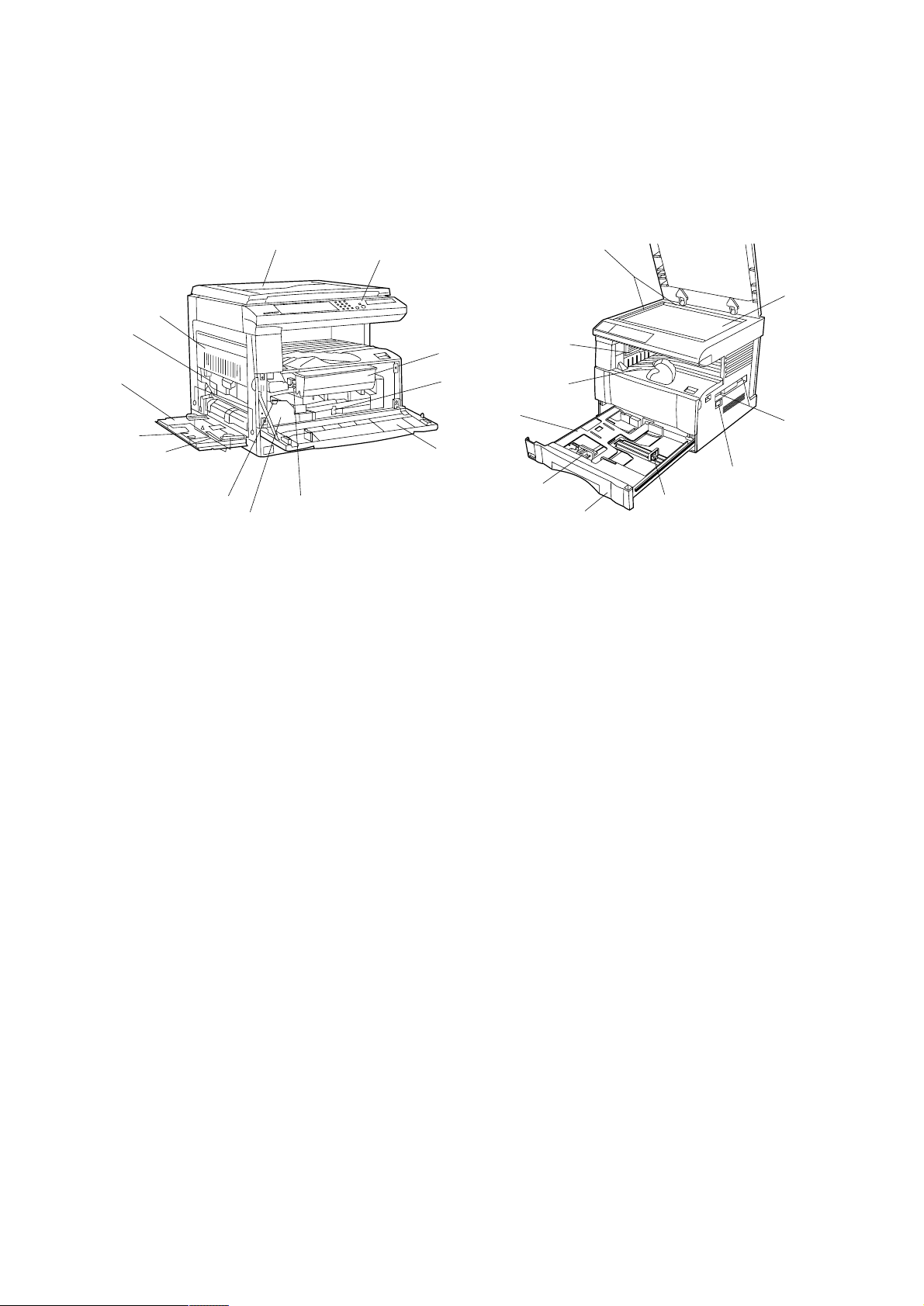
1-1-2 Parts names and their functions
(1) Copier
4
¤
6
3
5
0
9
1
2
!
Figure 1-1-1
1 Original cover
2 Operation panel
3 Paper conveying unit
4 Multi-Bypass
5 Insert guides
6 Support tray
7 T oner cartridge
8 Toner cartridge release lever
9 Waste toner tank
0 Waste toner tank release lever
! Cleaning shaft
@ Front cover
# Main switch
$ Copy store section
% Ejection section
^ Drawer
& Platen
* Original size scales
( Length adjustment plate
) Width adjustment lever
⁄ Drawer lift
¤ Handles for transport
7
8
@
⁄
*
&
%
$
¤
#
)
(
^
1-1-2
Page 14
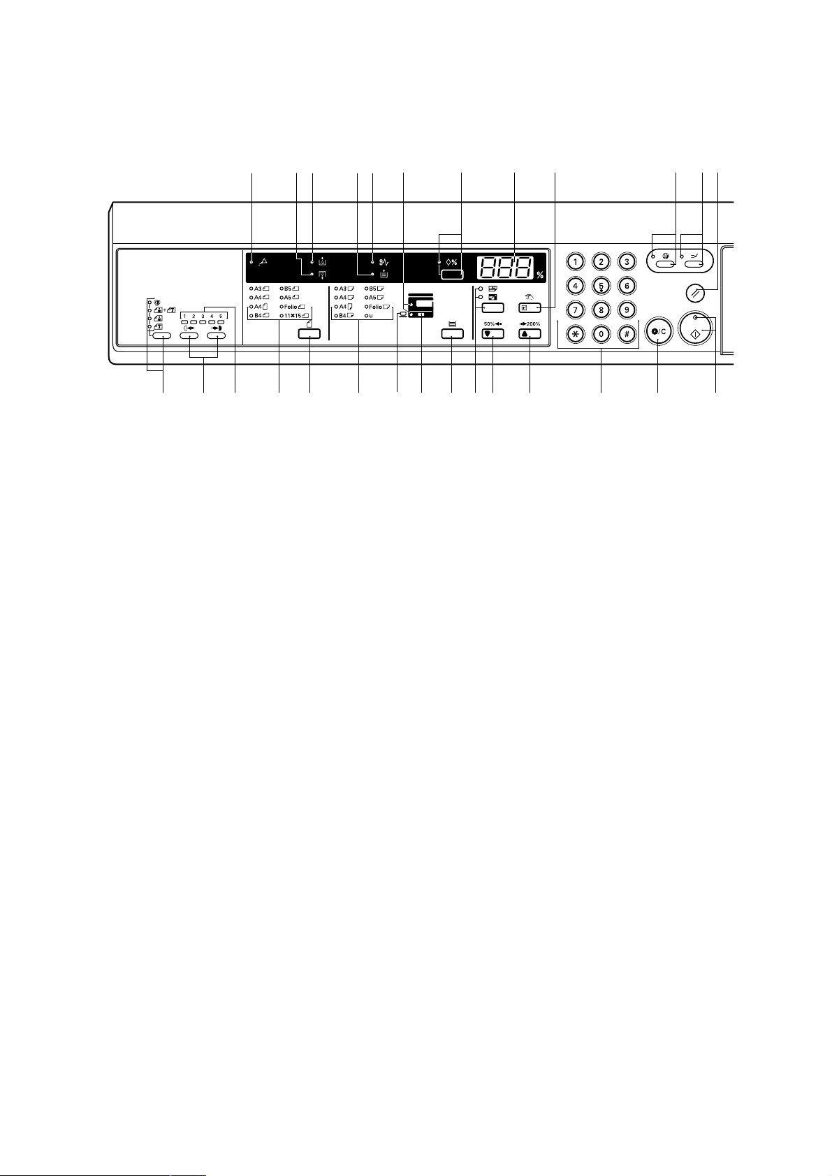
(2) Operation panel
2BV
¤⁄ )(‹%@876
fl›fi *& ^ $#!09 3 2 1$
1 Start key (Indicator)
2 Stop/Clear key
3 Numeric keys
4 Reset key
5 Interrupt key (Indicator)
6 Energy Saver (preheat) key (Indicator)
7 Manual/Enter key
8 Copy quantity/magnification display
9 Zoom (+) key
0 Zoom (-) key
! Auto mode selection key/APS/AMS indicators
@ Recall key (Indicator)
# Paper Select key
$ Drawer select indicators
54
Figure 1-1-2
% Misfeed location indicators
^ Paper size indicators
& Original key
* Original size indicators
( Misfeed indicator
) Add Paper indicator
⁄ Add Toner indicator
¤ Toner Disposal indicator
‹ Maintenance indicator
› Copy exposure adjustment keys
fi Copy exposure indicators
fl Image mode selection key/Auto Exposure/Text
& Photo/Photo/Text indicators
1-1-3
Page 15
2BV
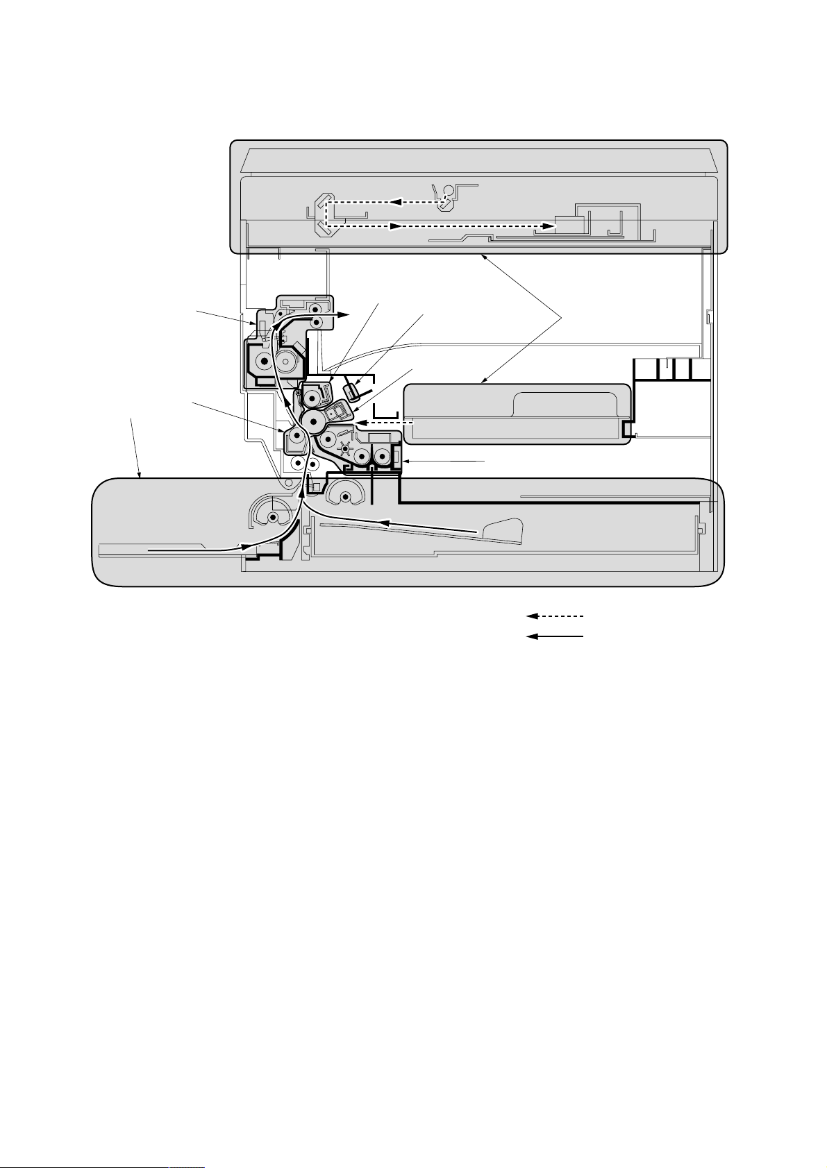
1-1-3 Machine cross section
1
8
5
6
7
2
4
Figure 1-1-3 Machine cross section
3
Light path
Paper path
1-1-4
1 Paper feed section
2 Main charging section
3 Optical section
4 Developing section
5 Transfer and paper conveying section
6 Cleaning section
7 Charge erasing section
8 Fixing section
Page 16

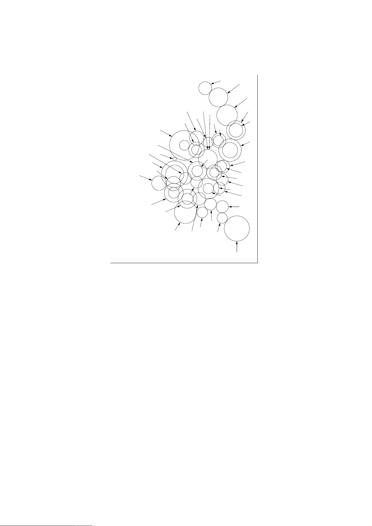
1-1-4 Drive system
(1) Drive system 1 (optical section)
2BV
8
1 Scanner motor gear
2 Gear 44/16
3 Gear 26
4 Scanner wire drum
7
Figure 1-1-4
5 Scanner wire
6 Scanner wire pulley
7 Scanner wire pulley
8 Scanner wire pulley
5
3
4
As viewed from machine front
6
1
2
1-1-5
Page 17
2BV
(2) Drive system 2 (drive motor drive train)
ˆ
¨
Á
´
Œ
7
8
&
„
2
1
9
4
—
3
‡
5
fi
fl
·
‚
⁄
!
^
%
0
As viewed from machine rear
#
)
‰
ˇ
›
‹
6
*
(
¤
@
$
1 Drive motor gear
2 Gear 58/30
3 Gear 48/27
4 Gear 60
5 Drum gear
6 Transfer roller gear
7 Gear 52/30
8 Gear 32/16
9 Gear 32/16
0 Gear 20
! Gear 20
@ Gear 20
# Idle gear 16
Figure 1-1-5
$ Bypass paper feed clutch gear
% Gear 16
^ Upper paper feed clutch gear
& Gear 30
* Gear 26/14
( Gear 20
) Registration clutch gear
⁄ Gear 15
¤ Gear 18
‹ Gear 20
› Gear 34/23
fi Gear 24
fl Gear 15
‡ Spiral gear 17
— Blade thrust gear 21
· Gear 16
‚ Idle gear
ΠGear 19
„ Gear 23
´ Gear 23
‰ Gear 29
ˇ Fixing gear 19
Á Heat roller gear 35
¨ Idle gear
ˆ Gear 21
1-1-6
Page 18
1-2-1 Drum
Note the following when handling or storing the drum.
• When removing the image formation unit, never expose the drum surface to strong direct light.
• Keep the drum at an ambient temperature between –20°C/–4°F and 40°C/104°F and at a relative humidity not higher
than 85% RH. Avoid abrupt changes in temperature and humidity.
• Avoid exposure to any substance which is harmful to or may affect the quality of the drum.
• Do not touch the drum surface with any object. Should it be touched by hands or stained with oil, clean it.
• If the machine is left open for more than 5 minutes for maintenance, remove the drum and store it in the drum storage
bag (Part No. 78369020).
1-2-2 Developer and toner
Store the developer and toner in a cool, dark place. Avoid direct light and high humidity.
1-2-3 Installation environment
1.Temperature: 10 - 35°C/50 - 95°F
2.Humidity: 15 - 85%RH
3.Power supply: 220 - 240 V AC, 2.8 A
4.Power source frequency: 50 Hz ±0.3%/60 Hz ±0.3%
5.Installation location
• Avoid direct sunlight or bright lighting. Ensure that the photoconductor will not be exposed to direct sunlight or other
strong light when removing paper jams.
• Avoid extremes of temperature and humidity, abrupt ambient temperature changes, and hot or cold air directed onto
the machine.
• Avoid dust and vibration.
• Choose a surface capable of supporting the weight of the machine.
• Place the machine on a level surface (maximum allowance inclination: 1° ).
• Avoid air-borne substances that may adversely affect the machine or degrade the photoconductor, such as
mercury, acidic of alkaline vapors, inorganic gasses, NOx, SOx gases and chlorine-based organic solvents.
• Select a room with good ventilation.
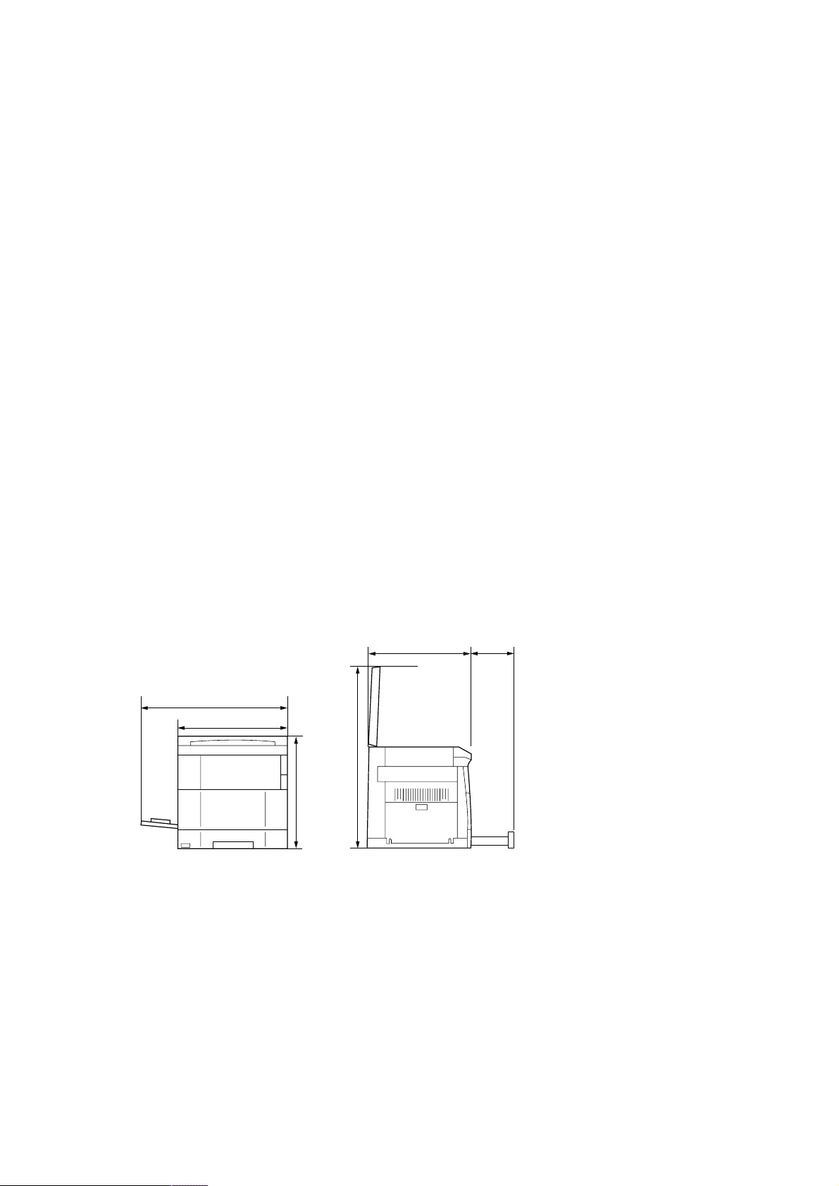
6.Allow sufficient access for proper operation and maintenance of the machine.
Machine front: 1000 mm/39
Machine right: 700 mm/27
3
/8" Machine rear: 100 mm/4"
5
/8" Machine left: 600 mm/235/8"
2BV
df
c
b
e
a: 455 mm/17
b: 550 mm/21
a
c: 718 mm/281/4"
d: 560 mm/22
e: 930 mm/36
15
5
1
5
/16"
/8"
/16"
/8"
f: 418 mm/167/16"
Figure 1-2-1 Installation dimensions
1-2-1
Page 19
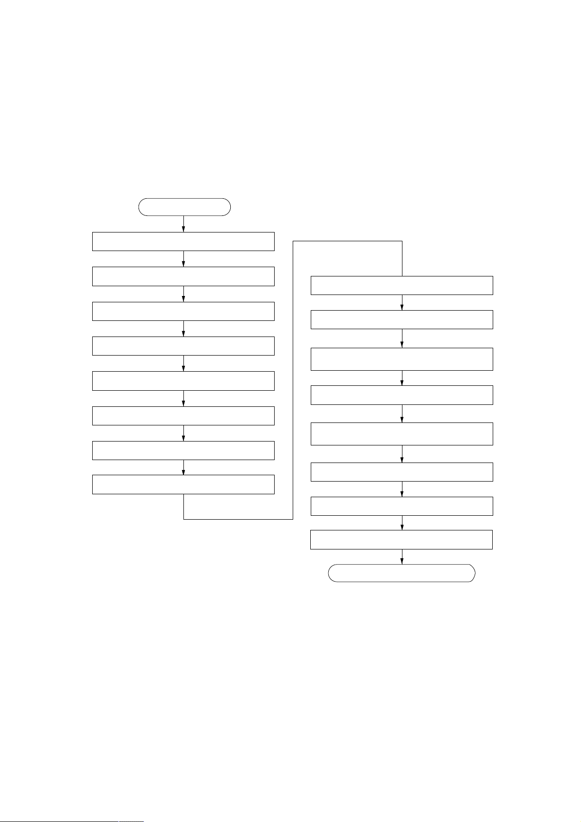
1-3-1 Unpacking and installation
(1) Installation procedure
Start
Unpack.
2BV
Remove the tapes.
Remove the pins holding light source units 1 and 2.
Install the optional devices.
Remove the image formation unit.
Load developer.
Release the cleaning blade.
Install a waste toner tank.
Adjust the fixing pressure.
Connect the power cord.
Carry out initial developer setting
(maintenance item U130).
Load paper.
Output an own-status report
(maintenance item U000).
Exit maintenance mode.
Install a toner cartridge.
Make test copies.
Completion of the machine installation.
1-3-1
Page 20
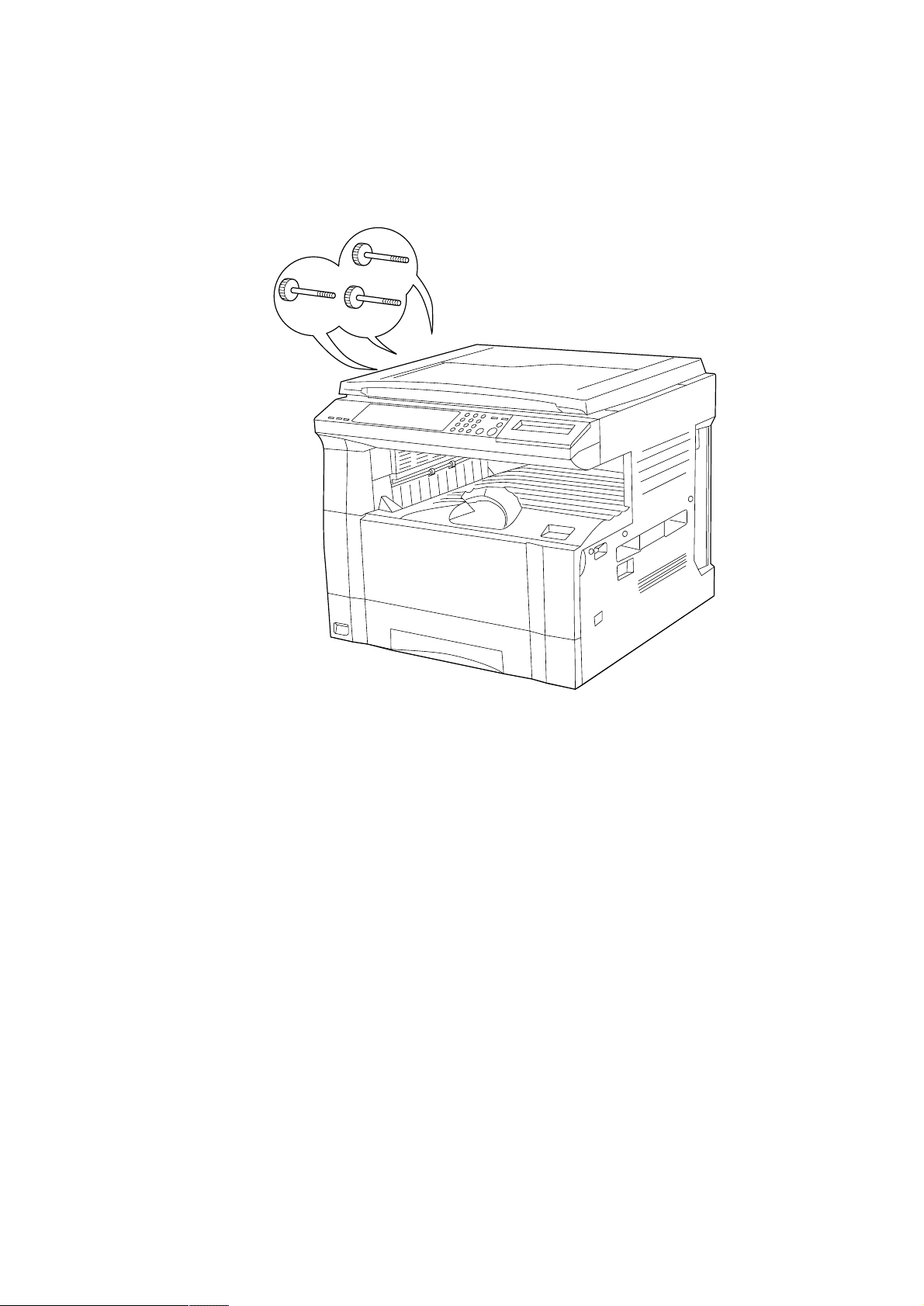
2BV
Light source unit 1 pins
Light source unit 2 pin
Figure 1-3-1
1-3-2
Page 21
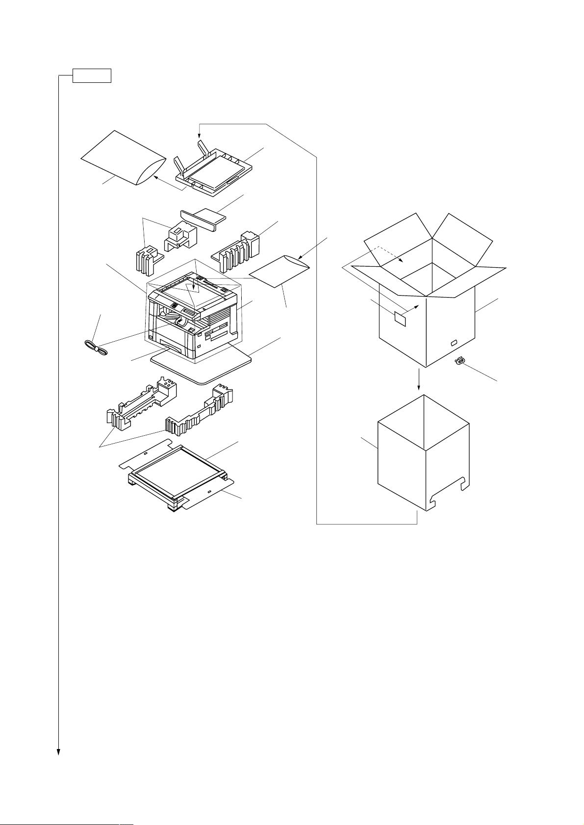
Unpack.
2BV
!
@
5
0
)
*(
4
7
9
1
4
8
^
%&⁄
3
#
2
$
1 Copier
2 Outer case
3 Inner frame
4 Upper pads
5 Bottom pads
6 Bottom case
7 Skid
8 Bottom plate
9 Spacer*
0 Machine cover
! Original cover
@ Plastic bag
1
6
Figure 1-3-2 Unpacking
# Bar code labels
$ Hinge joint
% Drawer size sheet
^ Plastic bag
& Error code label*
* Drawer spacers
( Drawer claw spacers
) Power cord
⁄ Paper storage bag
*1: 230 V specifications only.
*2: Asia and Oceania specifications only.
2
1-3-3
Page 22
2BV
Remove the tapes.
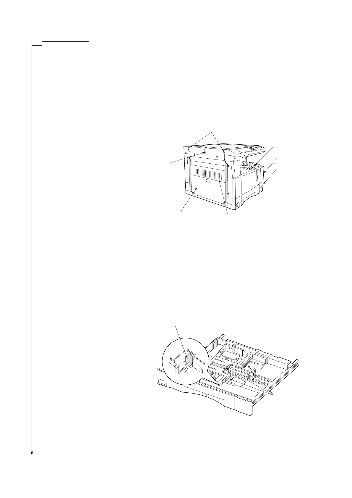
1. Remove the tape holding the front cover and the
power cord, and remove the tape binding the
power cord.
2. Remove the tape holding the drawer.
3. Remove the two tapes holding the paper
conveying unit and bypass tray.
4. Remove the three tapes holding the pins for light
source units 1 and 2.
Light source
unit 2 pin
Light source unit 1 pins
Power cord
Front cover
Drawer
5. Pull the drawer out and remove the tape holding
each of the drawer spacers and then the spacers.
6. Remove the tape holding the fulcrum of the
drawer lift inside the drawer.
Fulcrum of the drawer lift
Bypass tray
Paper conveying unit
Figure 1-3-3
1-3-4
Drawer spacers
Figure 1-3-4
Page 23
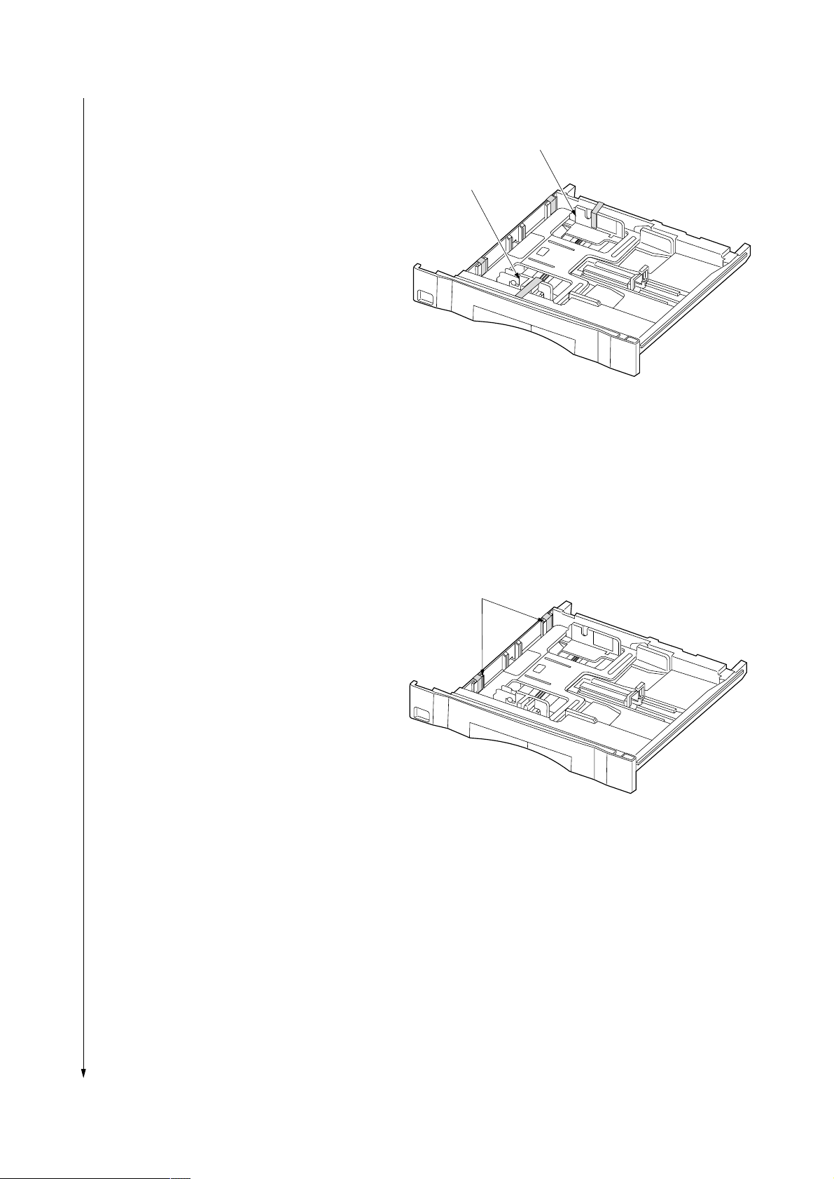
7. Remove the tape holding each of the front and
rear cursors.
2BV
Rear cursor
Front cursor
Figure 1-3-5
8. Remove the tape holding each of the drawer
claw spacers and then the spacers.
9. Refit the drawer.
Drawer claw spacers
Figure 1-3-6
1-3-5
Page 24
2BV
Remove the pins holding light source units 1 and 2.
1. Remove the two pins for light source unit 1 and
the pin for light source unit 2.
Light source unit 1 pins
Light source unit 2 pin
Figure 1-3-7
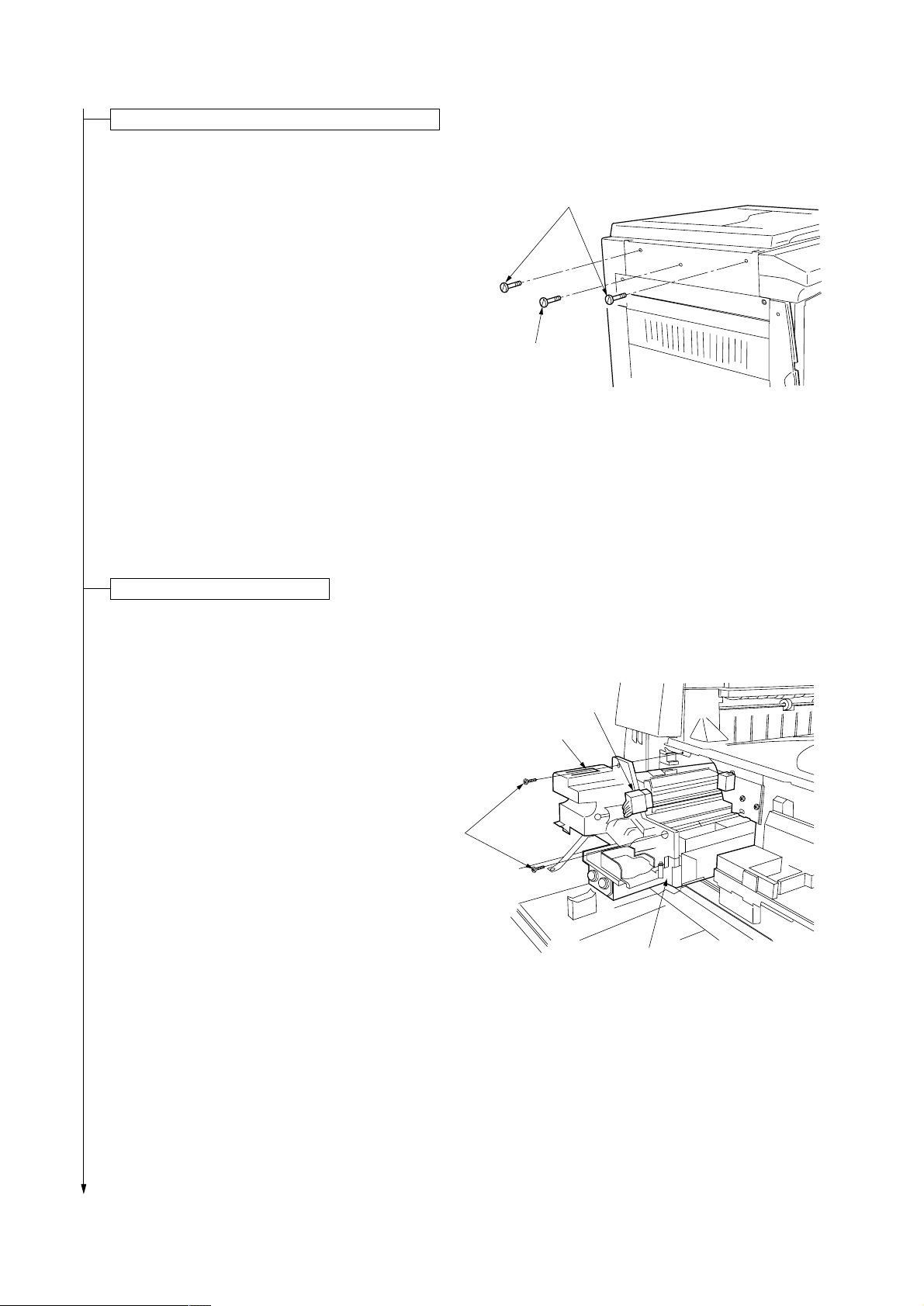
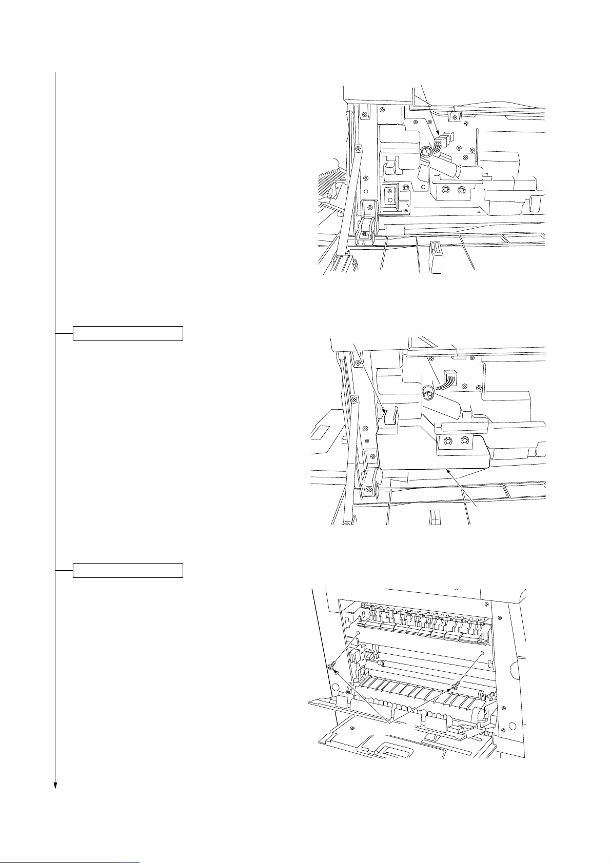
Remove the image formation unit.
1. Open the front cover, bypass tray and the paper
conveying unit.
2. Remove the two screws and disconnect the 12pin connector. While pressing the hook on the
front image formation cover, pull the image
formation unit out.
12-pin
Connector
Hook
Screws
Image formation unit
Figure 1-3-8
1-3-6
Page 25
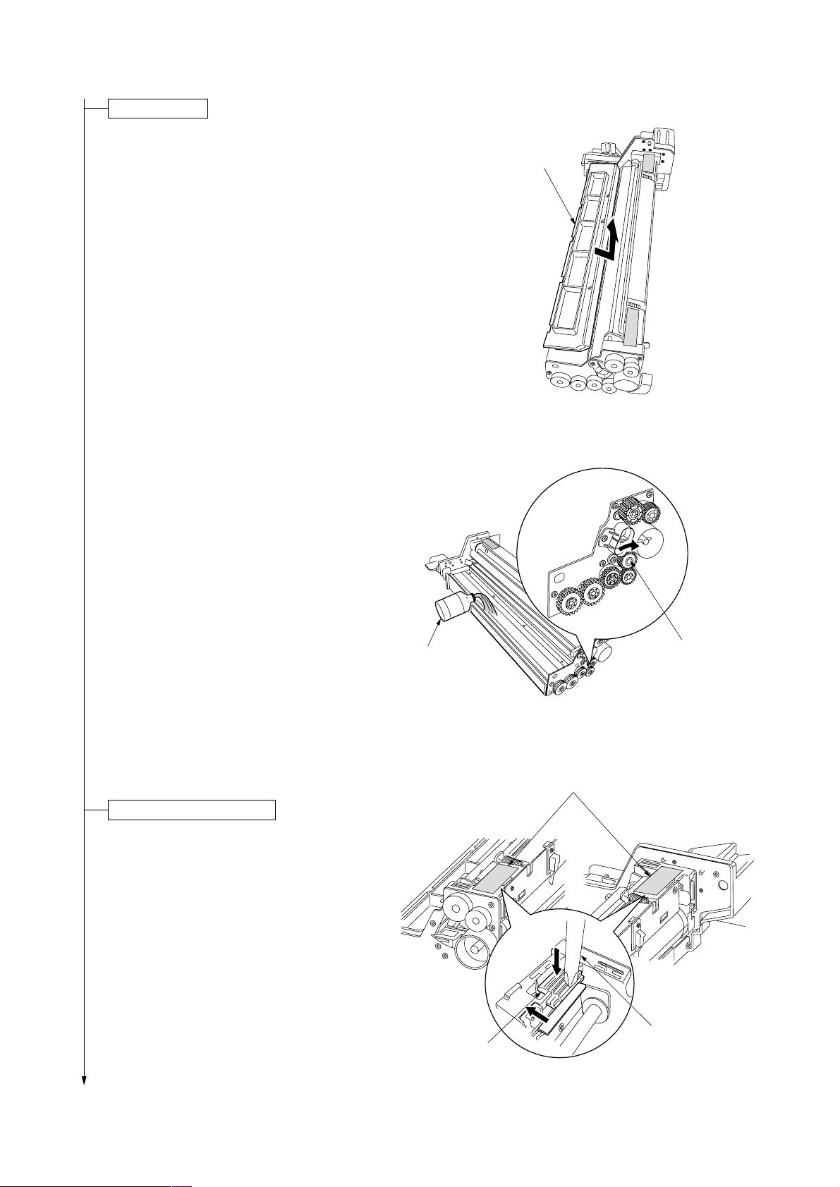
Load developer.
1. Remove the developing unit upper cover by
pushing and lifting it in the direction of the arrow
in the diagram.
Caution: Be sure to place the image formation
unit on a level surface when loading developer.
2. Shake the developer bottle well to agitate the
developer.
3. While turning the magnet roller gear in the
direction of the arrow in the diagram, uniformly
pour developer into the image formation unit.
Caution: Never turn the magnet roller gear in the
reverse direction.
2BV
Developing unit
upper cover
Figure 1-3-9
4.Refit the developing unit upper cover.
Release the cleaning blade.
1.Remove the tape holding each of the two
cleaning blade release levers. Apply the cleaning
blade to the drum by gently pushing the cleaning
blade release levers in the direction of the arrows
in the diagram using a screwdriver.
•The cleaning blade comes into contact with the
drum.
Developer
Cleaning blade
release lever
Magnet roller gear
Figure 1-3-10
Tapes
Screwdriver
Figure 1-3-11
1-3-7
Page 26
2BV
2.Check that the cleaning shaft is inserted as far as
it will go.
3. Refit the image formation unit using the two
screws.
4. Connect the 12-pin connector.
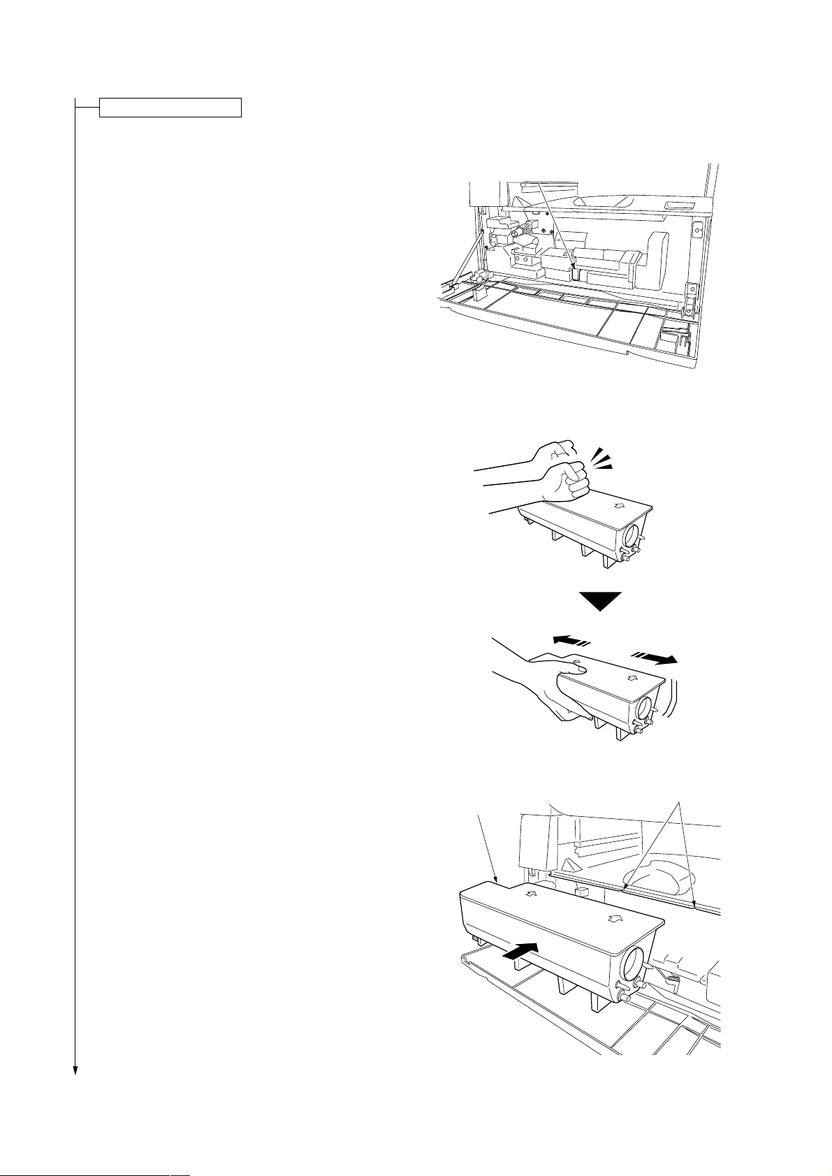
Install a waste toner tank.
1.While holding the waste toner tank release lever
up, fit the waste toner tank in the copier.
12-pin connector
Figure 1-3-12
Waste toner tank
release lever
2. Close the front cover.
Adjust the fixing pressure.
1. Remove the two blue screws.
2.Close the paper conveying unit and the bypass
tray.
1-3-8
Waste toner tank
Figure 1-3-13
Blue screws
Figure 1-3-14
Page 27

Connect the power cord.
1.Connect the power cord to the connector on the copier.
2.Insert the power plug into the wall outlet.
Carry out initial developer setting (maintenance item U130).
1.Turn the main switch on and enter the maintenance mode by entering “10871087” using the numeric keys.
2.Enter “130” using the numeric keys and press the start key.
3.Press the start key to execute the maintenance item.
The drive stops within approximately 4 minutes and the toner feed start level and toner sensor control voltage are
automatically set.
Each time the copy exposure adjustment keys are pressed, the settings for INPUT, CONTROL, TARGET and
HUMID are displayed on the copy quantity/magnification display in the order presented.
4.Press the stop/clear key.
Load paper.
1.Load paper in the drawer.
Caution: Loading paper before turning the main switch on may cause paper jams.
Output an own-status report (maintenance item U000).
1.Enter “000” using the numeric keys and press the start key.
2.Select “d-L” and press the start key to output a list of the current settings of the maintenance items.
3.Press the stop/clear key.
2BV
Exit maintenance mode.
1. Enter "001" using the numeric keys and press the start key.
The machine exits the maintenance mode.
1-3-9
Page 28
2BV
Install a toner cartridge.
1. Open the front cover.
2.Shift the toner cartridge release lever to the right
until it stops.
3.Tap the toner cartridge on the top five or six times
and shake it horizontally eight to ten times to
agitate the toner.
Toner cartridge release lever
Figure 1-3-15
4.Align the arrows on the top of the toner cartridge
with the cutouts in the eject tray and then insert
the cartridge into the copier.
5.Secure the toner cartridge by shifting the toner
cartridge release lever to the left until it stops.
6. Close the front cover.
1-3-10
Figure 1-3-16
Cutouts
Toner cartridge
Figure 1-3-17
Page 29

Make test copies.
1. Place an original and make test copies.
Check if the center lines of the bypass tray and
drawer are correct. If not, adjust the center lines.
Completion of machine installation.
2BV
1-3-11
Page 30

2BV
1-3-2 Setting initial copy modes
Factory settings are as follows:
Maintenance item
No.
U253 Switching between double and single counts Double count Double count
U254 Turning auto start function on/off On On
U255 Setting auto clear time 90 s 90 s
U256 Turning auto preheat/energy saver function on/off On On
U258 Switching copy operation at toner empty Single mode, Single mode,
detection 70 sheets 70 sheets
U260 Changing the copy count timing After ejection After ejection
U342 Setting the ejection restriction On On
U344 Setting preheat/energy saver mode Energy star Energy star
U348 Setting the copy density adjustment range Special area Special area
Contents
Metric Inch
Factory setting
1-3-12
Page 31

2BV
1-3-3 Copier management
In addition to a maintenance function for service, the copier is equipped with a management function which can be operated
by users (mainly by the copier administrator). In this copier management mode, settings such as default settings can be
changed.
(1) Using the copier management mode
• Executing a default setting item
Start
Press both of the copy exposure adjustment keys for 3 s.
Select an item using the zoom
+/– keys or numeric keys.
Press the enter key.
Execute the default
setting item (page 1-3-14).
Select “F00” and
press the enter key.
End
1-3-13
Page 32

2BV
(2) Copy default
User status report
Prints the details of the default settings.
1. Select “F01” and press the enter key.
If A4 paper is present, the list is automatically
printed out. Otherwise, select the paper source
and press the start key.
Exposure mode
Selects the image mode at power-on.
1. Select “F02” and press the enter key.
2. Select the exposure mode and press the enter
key.
Exposure mode: 1 (auto exposure)/
2 (text & photo)/3 (photo)/4 (text)
Exposure steps
Sets the number of exposure steps for the manual
exposure mode.
1. Select “F03” and press the enter key.
2. Select “5 steps” or “9 steps” and press the
enter key.
Setting range: 1 (5 steps)/2 (9 steps)
Auto exposure adjustment
Adjusts the exposure for the auto exposure mode.
1. Select “F04” and press the enter key.
2. Select the setting and press the enter key.
Setting range: 1 to 7
Text and photo original exposure adjustment
Adjusts the exposure to be used when text and
photo original is selected for the image mode.
1. Select “F05” and press the enter key.
2. Select the setting and press the enter key.
Setting range: 1 to 7
Text original exposure adjustment
Adjusts the exposure to be used when text original
is selected for the image mode.
1. Select “F06” and press the enter key.
2. Select the setting and press the enter key.
Setting range: 1 to 7
Photo original exposure adjustment
Adjusts the exposure to be used when photo
original is selected for the image mode.
1. Select “F07” and press the enter key.
2. Select the setting and press the enter key.
Setting range: 1 to 7
Paper selection
Sets whether the same sized paper as the original
to be copied is automatically selected.
1. Select “F08” and press the enter key.
2. Select “auto” or “manual” and press the enter
key.
Setting range: 1 (auto)/2 (manual)
AMS mode
Selects whether auto magnification selection or
100% magnification is to be given priority when the
sizes of the original and copy paper are different.
1. Select “F09” and press the enter key.
2. Select “auto magnification selection” or “same
size” and press the enter key.
Setting range: 1 (auto magnification selection)/
2 (same size)
Drawer paper size
Sets the paper size for the drawer so that it will be
automatically selected.
1. Select “F10” and press the enter key.
2. Select the paper size for the drawer and press
the enter key.
Paper size: 1 (A3)/2 (A4 vertical)/3 (A4)/
4 (B4)/5 (B5 vertical)/6 (A5 vertical)/7 (folio)
Bypass tray paper size
Sets the paper size for the bypass tray so that it will
be automatically selected.
1. Select “F11” and press the enter key.
2. Select the paper size for the bypass tray and
press the enter key.
Paper size: 1 (A3)/2 (A4 vertical)/3 (A4)/
4 (B4)/5 (B5 vertical)/6 (B5)/7 (folio)/
8 (no size setting*)
* Setting of non-standard size paper width for
bypass tray
Non-standard size paper width setting for bypass tray
Sets the paper width for the bypass tray to use
non-standard size paper.
1. Select “F12” and press the enter key.
2. Enter the setting and press the enter key.
Setting range: 100 to 297 mm
Copy limit
Sets the number of copies limit for multiple copying.
1. Select “F13” and press the enter key.
2. Enter the setting and press the enter key.
Setting range: 1 to 250 copies
1-3-14
Page 33

Silent mode
Selects whether or not to enter silent mode after
copying.
1. Select “F14” and press the enter key.
2. Select “on” or “off” and press the enter key.
Setting range: 1 (on)/2 (off)
Auto shutoff
Sets whether the auto shutoff function is available .
1. Select “F15” and press the enter key.
2. Select “on” or “off” and press the enter key.
Setting range: 1 (on)/2 (off)
Auto preheat time
Sets the auto preheat time.
1. Select “F16” and press the enter key.
2. Select the setting and press the enter key.
Setting range: 5 to 45 minutes (in 5-minute
increments)
1 (5 min)/2 (10 min)/3 (15 min)/4 (20 min)/
5 (25 min)/6 (30 min)/7 (35 min)/8 (40 min)/
9 45 min)
Note: Set the auto preheat time to be shorter
than the auto shutoff time.
2BV
Auto shutoff time
Sets the auto shutoff time.
1. Select “F17” and press the enter key.
2. Select the setting and press the enter key.
Setting range: 15 to 240 minutes (in 15-minute
increments)
1 (15 min)/2 (30 min)/3 (45 min)/4 (60 min)/
5 (75 min)/6 (90 min)/7 (105 min)/8 (120 min)/
9 (135 min)/10 (150 min)/11 (165 min)/
12 (180 min)/13 (195 min)/14 (210 min)/
15 (225 min)/16 (240 min)
Toner counter report
Prints the report on the toner consumption ratio.
1. Select “F18” and press the enter key.
If A4 paper is present, the list is automatically
printed out. Otherwise, select the paper source
and press the start key.
1-3-15
Page 34

2BV
1-3-4 Installing the total counter (option)
Procedure
1. Remove the right cover and eject tray.
2. Remove the Lumirror (polyester film) from the
right side of the copier.
3. Check the vertical orientation of the total
counter and then insert it into the opening in
the copier.
4. Connect the 2-pin connector of the total
counter to the 2-pin connector inside the
copier. Be sure to pass the cable of the total
counter connector through the cutout in the
copier inner frame.
5. Refit the removed parts.
6. Turn the main switch on and enter the
maintenance mode.
7. Run maintenance item U204 and change the
setting to “on”.
2-pin connector
2-pin connector
Cutout
Total counter
Figure 1-3-18
1-3-16
Page 35

1-4-1 Maintenance mode
The copier is equipped with a maintenance function which can be used to maintain and service the machine.
(1) Executing a maintenance item
Start
2BV
Enter 10871087.
Enter the number of the maintenance
item to be executed using the zoom +/keys or numeric keys.
Press the start key.
The maintenance item is run.
Press the stop/clear key.
Yes
Run the item again?
· · · · · · · Entering the maintenance mode
· · · · · · · Selecting a maintenance item
No
Yes
Run another maintenance
mode?
No
Enter 001 using the zoom +/- keys or
numeric keys, and press the print key.
End
· · · · · · · Exiting the maintenance mode
1-4-1
Page 36

2BV
(2) Maintenance mode item list
Section
General
Initialization
Drive, paper
feed, paper
conveying and
cooling system
Optical
High voltage
Developing
* Initial setting for executing maintenance item U020
Item
No. setting*
U000 Outputting an own-status report —
U001 Exiting the maintenance mode —
U004 Setting the machine number —
U005 Copying without paper —
U020 Initializing all data —
U021 Initializing memories —
U022 Initializing backup data —
U030 Checking motor operation —
U031 Checking switches for paper conveying —
U032 Checking clutch operation —
U033 Checking solenoid operation —
U034 Adjusting the print start timing
• Adjusting the leading edge registration 0
• Adjusting the center line 0
U035 Setting folio size
• Length 330
• Width 210
U051 Adjusting the amount of slack in the paper
• Regist data 0
U053 Performing fine adjustment of the motor speed
• Drive motor 0
• Polygon motor 0
U060 Adjusting the scanner input properties 12
U061 Turning the exposure lamp on —
U063 Adjusting the shading position 0
U065 Adjusting the scanner magnification
• Main scanning direction/auxiliary scanning direction 0
U066 Adjusting the leading edge registration for scanning an original on the 0
contact glass
U067 Adjusting the center line for scanning an original on the contact glass 0
U073 Checking scanner operation —
U088 Setting the input filter (moiré reduction mode) Off
U089 Outputting a MIP-PG pattern —
U091 Checking shading —
U092 Adjusting the scanner automatically —
U093 Setting the exposure density gradient
• Text/text and photo/photo mode 0
U100 Setting the surface potential 184
U101 Setting high voltages
• Developing bias 193/38
• Transfer voltage 115
• Transfer voltage output timing –176
U109 Setting the drum type H
U110 Checking/clearing the drum count —
U111 Checking/clearing the drum drive time —
U130 Initial setting for the developer —
U131 Setting the toner sensor control voltage 155
U132 Replenishing toner forcibly —
U135 Checking toner feed motor operation —
U155 Displaying the toner sensor output —
Maintenance item contents
1-4-2
Initial
Page 37

2BV
Section
Developing
Fixing and
cleaning
Operation
panel and
support
equipment
Mode setting
Image
processing
Others
Item
No. setting*
U156 Changing the toner control level
• Toner feed start level 100
• Toner empty level 44
U157 Checking/clearing the developing drive time —
U158 Checking/clearing the developing count —
U161 Setting the fixing control temperature
• Primary stabilization fixing temperature 135
• Secondary stabilization fixing temperature 160
• Regular stabilization control temperature 180
• Temperature to be deducted from the regular control temperature 0
when copying onto small-sized paper
U162 Stabilizing fixing forcibly —
U163 Resetting the fixing problem data —
U196 Turning the fixing heater on —
U199 Checking the fixing temperature —
U200 Turning all LEDs on —
U204 Setting the presence or absence of a total counter —
U250 Setting the maintenance cycle 100
U251 Checking/clearing the maintenance count —
U252 Setting the destination Japan
U253 Switching between double and single counts Double count
U254 Turning auto start function on/off On
U255 Setting auto clear time 120
U256 Turning auto preheat/energy saver function on/off On
U258 Switching copy operation at toner empty detection Single mode,
U260 Changing the copy count timing After ejection
U332 Setting the size conversion factor —
U342 Setting the ejection restriction On
U344 Setting preheat/energy saver mode Energy star
U345 Setting the value for maintenance due indication 0
U348 Setting the copy density adjustment range Normal
U402 Adjusting margins of image printing —
U403 Adjusting margins for scanning an original on the contact glass —
U901 Checking/clearing copy counts by paper feed locations —
U903 Checking/clearing the paper jam counts —
U904 Checking/clearing the service call counts —
U906 Resetting partial operation control —
U910 Clearing the black ratio data —
U917 Setting the reading/writing of backup data Read
U990 Checking/clearing the time for the exposure lamp to light —
U993 Outputting a VTC-PG pattern —
U998 Outputting the memory list —
Maintenance item contents
Initial
70
* Initial setting for executing maintenance item U020
1-4-3
Page 38

2BV
(3) Contents of maintenance mode items
Maintenance
item No.
U000 Outputting an own-status report
Description
Outputs lists of the current settings of the maintenance items, and paper jam and service call occurrences.
Purpose
To check the current setting of the maintenance items, or paper jam or service call occurrences.
Before initializing the backup RAM, output a list of the current settings of the maintenance items to reenter the
settings after initialization or replacement.
Method
1. Press the start key. A selection item appears.
2. Select the item to be output using the copy exposure adjustment keys.
Display Output list
d-L List of the current settings of the maintenance modes
J-L List of the paper jam occurrences
C-L List of the service call occurrences
3. Press the start key. The interrupt copy mode is entered and a list is output.
1
When A4/11" × 8
/2" paper is available , a report of this size is output. If not, specify the paper f eed location.
When output is complete, the selected item appears.
Completion
Press the stop/clear key while a selection item is display ed. The indication for selecting a maintenance item No .
appears.
U001 Exiting the maintenance mode
Description
Exits the maintenance mode and returns to the normal copy mode.
Purpose
To exit the maintenance mode.
Method
Press the start key. The normal copy mode is entered.
U004 Setting the machine number
Description
Displays and changes the machine number.
Purpose
To check or set the machine number.
Method
Press the start key. The currently set machine number is displayed.
Setting
1. Select the item by lighting a copy exposure indicator using the copy exposure adjustment keys.
2. Enter the last six digits of the machine number using the numeric or zoom +/– keys.
Do not enter the first two digits, 3 and 7.
Copy exposure indicator Description Setting range Initial setting
Exp. 1 First 3 digits 000 to 999 000
Exp. 2 Last 3 digits 000 to 999 000
3. Press the start key. The machine number is set. The indication for selecting a maintenance item No.
appears.
Completion
To exit this maintenance item without changing the current setting, press the stop/clear key. The indication for
selecting a maintenance item No. appears.
Description
1-4-4
Page 39

2BV
Maintenance
item No.
U005 Copying without paper
Description
Simulates the copy operation without paper feed.
Purpose
To check the overall operation of the machine.
Method
1. Press the start key. A selection item appears.
2. Select the item to be operated using the copy exposure adjustment keys.
Display Operation
P Only the copier operates.
3. Press the interrupt key.
4. Set the operation conditions required. Changes in the following settings can be made.
• Paper feed locations
• Magnifications
• Number of copies: continuous copying is performed when set to 250.
• Copy density
• Keys on the operation panel other than the energy saver (preheat) key
5. To control the paper feed pulley, remove all the paper in the drawers, or the drawers. With the paper
present, the paper feed pulley does not operate.
6. Press the start key. The operation starts.
Copy operation is simulated without paper under the set conditions. When operation is complete, the
selected item appears.
7. To stop continuous operation, press the stop/clear key.
Completion
Press the stop/clear key at the screen for selecting an item. The indication f or selecting a maintenance item No .
appears.
U020 Initializing all data
Description
Initializes all the backup RAM on the main PCB to return to the original settings.
Purpose
Used when replacing the main PCB.
Method
1. Press the start key.
2. Select “on” using the zoom +/– keys.
Display Operation
––– Canceling initialization
on Executing initialization
3. Press the start key. All data in the backup RAM is initialized, and the original settings for Japan specifications are set.
When initialization is complete, the machine automatically returns to the same status as when the main
switch is turned on.
Completion
To exit this maintenance item without executing initialization, press the stop/clear key. The indication for
selecting a maintenance item No. appears.
Description
1-4-5
Page 40

2BV
Maintenance
item No.
U021 Initializing memories
Description
Initializes the setting data other than that for adjustments due to variations between respective machines, i.e.,
settings for counters, service call history and mode settings. As a result, initializes the backup RAM according
to the specifications depending on the destination selected in U252.
Purpose
Used to return the machine settings to the factory settings.
Method
1. Press the start key.
2. Select “on” using the zoom +/– keys.
Display Operation
––– Canceling initialization
on Executing initialization
3. Press the start key. All data other than that for adjustments due to variations between machines is
initialized based on the destination setting. When initialization is complete, the machine automatically
returns to the same status as when the main switch is turned on.
Completion
Press the stop/clear key. The indication for selecting a maintenance item No. appears.
U022 Initializing backup data
Description
Initializes only the data set for the optical section.
Purpose
To be executed after replacing the scanner unit.
Method
1. Press the start key. “A” appears.
2. Press the start key.
3. Select “on” using the zoom +/– keys.
Display Operation
––– Canceling initialization
on Executing initialization
4. Press the start key. The data for the optical section (U060 to 093, U403 and U990) is initialized.
Completion
Press the stop/clear key. The indication for selecting a maintenance item No. appears.
U030 Checking motor operation
Description
Drives the drive motor.
Purpose
To check the operation of the drive motor.
Method
1. Press the start key. A selection item appears.
2. Select the motor to be operated using the copy exposure adjustment keys.
3. Press the start key. The selected motor operates.
Display Motor
A Drive motor (DM)
4. To stop operation, press the stop/clear key.
Completion
Press the stop key after operation stops. The indication for selecting a maintenance item No. appears.
Description
1-4-6
Page 41

2BV
Maintenance
item No.
U031 Checking switches for paper conveying
Description
Displays the on-off status of each paper detection switch on the paper path.
Purpose
To check if the switches for paper conveying operate correctly.
Method
1. Press the start key.
2. Tur n each switch on and off manually to check the status.
When the on-status of a switch is detected, the corresponding original size indicator lights.
Original size indicator Switch
A3/11" × 17" Eject switch (ESW)
1
A4/8
/2" × 11" Registration switch (RSW)
Completion
Press the stop/clear key. The indication for selecting a maintenance item No. appears.
U032 Checking clutch operation
Description
Turns each clutch on.
Purpose
To check the operation of each clutch.
Method
1. Press the start key. A selection item appears.
2. Select the clutch to be operated using the copy exposure adjustment keys.
3. Press the start key. The selected clutch turns on for 1 s.
Display Clutch
P1 Paper feed clutch (PFCL)
Pb Bypass paper feed clutch (BYPPFCL)
2F Registration clutch (RCL)
Description
Completion
Press the stop/clear key. The indication for selecting a maintenance item No. appears.
1-4-7
Page 42

2BV
Maintenance
item No.
U033 Checking solenoid operation
Description
Turns the solenoid on.
Purpose
To check the operation of the solenoid.
Method
1. Press the start key. A selection item appears.
2. Select the desired operation using the copy exposure adjustment keys.
3. Press the start key. The selected operation starts.
Display Operation
A Turning the main switch off
Completion
Press the stop/clear key. The indication for selecting a maintenance item No. appears.
U034 Adjusting the print start timing
Adjustment
See pages 1-6-9 and 10.
U035 Setting folio size
Description
Changes the image area for copying onto folio size paper.
Purpose
To prevent the image at the trailing edge, or right or left side of the paper from not being copied by setting the
actual size of the folio paper used.
Method
Press the start key.
Setting
1. Select the item by lighting a copy exposure indicator using the copy exposure adjustment keys.
2. Change the setting using the zoom +/– keys.
Copy exposure indicator Setting Setting range Initial setting
Exp. 1 Length 330 to 356 mm 330
Exp. 2 Width 200 to 220 mm 210
3. Press the start key. The value is set.
Completion
Press the stop/clear key. The indication for selecting a maintenance item No. appears.
U051 Adjusting the amount of slack in the paper
Adjustment
See page 1-6-12.
Description
1-4-8
Page 43

2BV
Maintenance
item No.
U053 Performing fine adjustment of the motor speed
Description
Performs fine adjustment of the speeds of the motors.
Purpose
Used to adjust the speed of the respective motors when the magnification is not correct.
Method
Press the start key.
Setting
1. Select the item by lighting a copy exposure indicator using the copy exposure adjustment keys.
2. Change the setting using the zoom +/– keys.
Copy exposure indicator Description Setting range Initial setting
Exp. 1 Drive motor speed adjustment –5.0 to +5.0 0
Exp. 2 Polygon motor speed adjustment –5.0 to +5.0 0
Drive motor speed adjustment (unit: %)
Increasing the setting makes the image longer in the auxiliary scanning direction, and decreasing it makes
the image shorter in the auxiliary scanning direction.
Polygon motor speed adjustment (unit: %)
Increasing the setting makes the image longer in the main scanning direction and shorter in the auxiliary
scanning direction; decreasing the setting makes the image shorter in the main scanning direction and
longer in the auxiliary scanning direction.
3. Press the start key. The value is set.
Interrupt copy mode
While this maintenance item is being performed, a VTC pattern shown below is output in interrupt copy mode.
Correct values for an A3/11" × 17" output are:
A = 300 ± 0.75 mm
B = 260 ± 1.3 mm
Description
B
A
Figure 1-4-1
Adjustment
1. Output an A3/11" × 17" VTC pattern in interrupt mode.
2. Measure A and B on the VTC pattern (Figure 1-4-1), and perform the following adjustments if they are
different from the correct sizes:
A: Drive motor speed adjustment
B: Polygon motor speed adjustment
Completion
Press the stop/clear key at the screen for selecting an item. The indication f or selecting a maintenance item No .
appears.
1-4-9
Page 44

2BV
Maintenance
item No.
U060 Adjusting the scanner input properties
Description
Adjusts the image scanning density.
Purpose
Used when the entire image appears too dark or light.
Method
Press the start key.
Setting
1. Change the setting using the zoom +/– keys.
Description Setting range Initial setting
Image scanning density 0 to 23 12
Increasing the setting makes the density lower, and decreasing it makes the density higher.
2. Press the start key. The value is set.
Interrupt copy mode
While this maintenance item is being performed, copying from an original can be made in interrupt copy mode.
Completion
Press the stop/clear key at the screen for selecting an item. The indication f or selecting a maintenance item No .
appears.
Caution
The following settings are also reset to the initial values by performing this maintenance item:
• Exposure density gradient set in maintenance mode (U093)
• Exposure set in the copy default item of the copier management mode
U061 Turning the exposure lamp on
Description
Turns the exposure lamp on.
Purpose
To check the exposure lamp.
Method
1. Press the start key. “on” appears.
2. Press the start key. The exposure lamp lights.
3. To tur n the exposure lamp off, press the stop/clear key.
Completion
Press the stop/clear key. The indication for selecting a maintenance item No. appears.
U063 Adjusting the shading position
Description
Changes the shading position.
Purpose
Used when white lines continue to appear longitudinally on the image after the shading plate is cleaned. This is
due to flaws or stains inside the shading plate. To pre vent this problem, the shading position should be changed
so that shading is possible without being affected by the flaws or stains.
Method
1. Press the start key.
2. Change the setting using the zoom +/– keys.
Description Setting range Initial setting Change in value per step
Shading position –5 to +5 0 0.17 mm
Increasing the setting moves the shading position toward the machine right, and decreasing it moves the
position toward the machine left.
3. Press the start key. The value is set.
Interrupt copy mode
While this maintenance item is being performed, copying from an original can be made in interrupt copy mode.
Completion
Press the stop/clear key at the screen for adjustment. The indication for selecting a maintenance item No.
appears.
Description
1-4-10
Page 45

2BV
Maintenance
item No.
U065 Adjusting the scanner magnification
Adjustment
See pages 1-6-26 and 27.
U066 Adjusting the leading edge registration for scanning an original on the contact glass
Adjustment
See page 1-6-28.
U067 Adjusting the center line for scanning an original on the contact glass
Adjustment
See page 1-6-29.
U073 Checking scanner operation
Description
Simulates the scanner operation under arbitrary conditions.
Purpose
To check scanner operation.
Method
1. Press the start key.
2. Select the item to be changed by lighting a copy exposure indicator using the copy exposure adjustment
keys.
3. Change the setting using the zoom +/– keys.
Copy exposure indicator Operating conditions Setting range
Exp. 1 Magnification 50 to 200%
Exp. 2 Paper size See below.
Exp. 3 On and off of the exposure lamp on or off
Description
Paper size for each setting
Setting Paper size Setting Paper size
8 A4 40 A4R
9 B5 41 B5R
36 A3 42 A5R
39 B4 47 Folio
4. Press the start key. Scanning starts under the selected conditions.
5. To stop operation, press the stop/clear key.
Completion
Press the stop/clear key when scanning stops. The indication for selecting a maintenance item No. appears.
1-4-11
Page 46

2BV
Maintenance
item No.
U088 Setting the input filter (moiré reduction mode)
Description
Turns moiré reduction mode on and off by switching the input filter on and off.
Purpose
Used to prevent regular density unevenness (moiré) on halftone image areas of the copy image in text mode
and text and photo mode. Such moiré is more likely to appear when an enlargement or reduction copy is made
in text mode from an original containing large halftone image areas.
Method
Press the start key.
Setting
1. Select “on” or “oFF” using the zoom +/– keys. The selected item is displayed in reverse.
Display Description
on Moiré reduction mode
oFF Normal copy mode
Initial setting: oFF
If moiré on the copy image is significant, change the setting to “on”. Note that when the moiré reduction
mode is turned on, the resolution may be slightly reduced.
2. Press the start key. The value is set. The indication for selecting a maintenance item No. appears.
Completion
To exit this maintenance item without changing the current setting, press the stop/clear key. The indication for
selecting a maintenance item No. appears.
U089 Outputting a MIP-PG pattern
Description
Selects and outputs a MIP-PG pattern created in the copier.
Purpose
When performing respective image printing adjustments, used to check the machine status apart from that of
the scanner with a non-scanned output MIP-PG pattern.
Method
1. Press the start key.
2. Select the MIP-PG pattern to be output using the copy exposure adjustment keys.
Display Setting Setting range Initial setting
G-5 Gray scale - 180 Mono level 0 to 255 180
1-d 1-dot level - -
3. Press the size select key. The machine enters the PG pattern output mode.
4. Press the start key. A MIP-PG pattern is output.
Completion
Press the stop/reset key. The indication for selecting a maintenance item No. appears.
Description
1-4-12
Page 47

2BV
Maintenance
item No.
U091 Checking shading
Description
Performs scanning under the same conditions as before and after shading is performed, displaying the original
scanning values at nine points of the contact glass.
Purpose
To check the change in original scanning values before and after shading. The results may be used to decide
the causes for fixing unevenness (uneven density) of the gray area of an image: either due to optical (shading
or CCD) or other problems.
Also to check the causes for a white or black line appearing longitudinally.
Method
1. Press the start key. A selection item appears.
2. Select the item to be operated using the zoom +/– keys.
Display Output list
on Performs scanning before shading and displays the result.
oFF Performs scanning after shading and displays the result.
3. Press the start key. Scanning is performed under the selected conditions and the result is displayed.
4. Change the measurement point by lighting a copy exposure indicator or making one flash using the copy
exposure adjustment keys. For the correspondence between the measurement points and the copy
exposure indicators, see Figure 1-4-2.
Description
20 mm from the machine left
200 mm from the machine left
400 mm from the machine left
123
456
789
100 mm from the machine
center toward machine front
Machine center
100 mm from machine
center toward machine rear
Point Copy exposure indicator
1 Exp. 1 lights.
2 Exp. 2 lights.
3 Exp. 3 lights.
4 Exp. 4 lights.
5 Exp. 5 lights.
6 Exp. 1 flashes.
7 Exp. 2 flashes.
8 Exp. 3 flashes.
9 Exp. 4 flashes.
Figure 1-4-2
1-4-13
Page 48

2BV
Maintenance
item No.
U091
(cont.)
U092 Adjusting the scanner automatically
When scanning is performed before shading, the scan value at the machine center should be slightly
different from those at the machine front and rear. When scanning is perf ormed after shading, there should
be no difference between respective v alues. Any diff erences between the v alues at machine front and rear
indicates that scanner problem causes the fixing unevenness.
If the displayed results indicate no shading problems, the fixing unevenness (uneven copy density) is
caused by factors other than in the scanner section (shading or CCD).
If a black line appears, the cause may be assumed based on the results of the scanning operation before
shading: if a white line appears, they may be assumed based on the results of the scanning operation after
shading. Note that depending on the thickness and location of the black or white line, it may not be possible
to use this method to determine the cause. This is because the displa yed v alues obtained from scanning at
the limit of nine points are insufficient to provide significant information.
5. Press the stop/clear key. The selected item appears.
Completion
Press the stop/clear key while a selection item is displayed. The indication for selecting a maintenance item
No. appears.
Description
Makes auto scanner adjustments in the order below using the specified original.
• Adjusting the scanner center line (U067)
• Adjusting the scanner leading edge registration (U066)
• Adjusting scanner magnification in the auxiliary direction (U065)
When this maintenance item is performed, the settings in U065, U066 and U067 are also changed.
Purpose
Used to make respective auto adjustments for the scanner.
Method
1. Place the specified original (P/N: 2AC68240) on the contact glass.
2. Press the start key. “on” appears.
3. Press the start key. Auto adjustment starts. When adjustment is complete, “Gd” appears.
4. Display each setting value after adjustment by lighting a copy exposure indicator using the copy exposure
adjustment keys.
Copy exposure indicator Setting value
Exp. 2 Scanner center line
Exp. 3 Scanner leading edge registration
Exp. 4 Scanner magnification in the auxiliary scanning direction
If a problem occurs during auto adjustment, “nG” is displayed and operation stops. Lighting the copy
exposure indicator exp. 2 and then exp. 3 using the copy exposure adjustment keys will display the error
code. Determine the details of the problem and either repeat the procedure from the beginning, or adjust
the remaining items manually by running the corresponding maintenance items.
Completion
Press the stop/clear key after auto adjustment is complete. The indication f or selecting a maintenance item No .
appears.
If the stop/clear key is pressed during auto adjustment, adjustment stops and no settings are changed.
Description
1-4-14
Page 49

2BV
Maintenance
item No.
U093 Setting the exposure density gradient
Description
Changes the exposure density gradient in manual density mode, depending on respective image modes (text,
text and photo, photo).
Purpose
T o set ho w the image density is altered by a change of one step in the manual density adjustment. Also used to
make copy image darker or lighter.
Start
1. Press the start key. A selection item appears.
2. Select the image mode to be adjusted by lighting image mode LEDs using the image mode selection key.
3. Press the start key. The machine enters the setting mode.
Image mode LEDs Description
Auto Exposure
Text & Photo
Photo
Text
Auto Exposure
Text & Photo
Photo
Text
Auto Exposure
Text & Photo
Photo
Text
Density in text mode
Density in text and photo mode
Density in photo mode
: Off, : On
Description
1-4-15
Page 50

2BV
Maintenance
item No.
U093
(cont.)
Setting
1. Select the item to be adjusted by lighting a copy exposure indicator using the copy exposure adjustment
Description
keys.
2. Adjust the setting using the zoom +/– keys.
Copy exposure
indicator
Description Setting range Initial setting
Exp. 1 Change in density when manual density is set dark 0 to 3 0
Exp. 2 Change in density when manual density is set light 0 to 3 0
Increasing the setting makes the change in density larger, and decreasing it makes the change smaller.
Image density
Dark
Light
Light
Density adjustment range: Special area
Set to DARKERSet to LIGHTER
Center
Density adjustment range: Normal
Setting: 0Setting: 3
Density adjustment
Dark
Figure 1-4-3 Exposure density gradient
3. Press the start key. The value is set.
4. Press the stop/clear key. The selected item appears.
Interrupt copy mode
While this maintenance item is being performed, copying from an original can be made in interrupt copy mode.
Completion
Press the stop/clear key while a selection item is display ed. The indication for selecting a maintenance item No .
appears.
1-4-16
Page 51

2BV
Maintenance
item No.
U100 Setting the surface potential
Description
Changes the surface potential by changing the grid control voltage. Also performs main charging.
Purpose
To set the surface potential or check main charging. Also used when reentering data after initializing the set
data.
Start
1. Press the start key. A selection item appears.
2. Select the item using the copy exposure adjustment keys.
Display (copy exposure indicator) Description
——— (exp. 1) Changing the grid control voltage
on1 (exp. 2) Turning the main charger on
on2 (exp. 3) Turning the main charger on and the laser scanner unit
Method for main charger output
1. Press the start key. The selected operation starts.
2. To stop operation, press the stop/clear key.
Setting the grid control voltage
1. Change the setting using the zoom +/– keys.
Description Setting range Initial setting
Grid control voltage 0 to 255 184
Increasing the setting makes the surface potential higher, and decreasing it makes the potential lower.
Change in value per step: approximately 3.6 V
2. Press the start key. The value is set.
Interrupt copy mode
While this maintenance item is being performed, copying from an original can be made in interrupt copy mode.
Completion
Press the stop/clear key when main charger output stops while a selection item is displayed. The indication for
selecting a maintenance item No. appears.
Description
on and off
1-4-17
Page 52

2BV
Maintenance
item No.
U101 Setting high voltages
Description
Changes the developing bias voltage and transfer voltage by changing the developing bias control voltage and
transfer control voltage. Also checks the transfer output voltage.
Purpose
To check and change high voltages other than the main charger voltage.
Start
1. Press the start key. A selection item appears.
2. Select the item to be set or checked by lighting image mode LEDs using the image mode selection key.
Image mode LEDs Description
: Off, : On
Setting the developing bias
1. Select the item to be adjusted by lighting a copy exposure indicator using the copy exposure adjustment
keys.
2. Change the setting using the zoom +/– keys.
Copy exposure indicator Description Setting range Initial setting
Exp. 1 Developing bias control voltage 25 to 255 193
Exp. 2 Developing bias control voltage 25 to 255 38
Increasing the setting makes the developing bias higher and the image darker; decreasing it makes the
bias lower and the image lighter.
3.Press the start key. The value is set.
Setting the transfer voltage
1. Select the item to be adjusted by lighting a copy exposure indicator using the copy exposure adjustment
keys.
2. Change the setting using the zoom +/– keys.
Copy exposure indicator Description Setting range Initial setting
Exp. 1 Transfer control voltage 0 to 255 115
Exp. 2 Transfer voltage output timing –250 to +250 –176
Increasing the exp. 1 setting makes the transf er v oltage higher , and decreasing it mak es the v oltage low er .
Increasing the exp. 2 setting makes the transfer voltage output timing later and improves paper separation
performance.
3. Press the start key. The value is set.
4. To check the transfer voltage output, light the copy exposure indicator exp. 3 using the copy exposure
adjustment keys and press the start key. The currently set transfer voltage is output.
5. To stop the transfer voltage output, press the stop/clear key.
Interrupt copy mode
While this maintenance item is being performed, copying from an original can be made in interrupt copy mode.
Completion
Press the stop/clear key while a selection item is displayed. The indication for selecting a maintenance item
No. appears.
Auto Exposure
Text & Photo
Photo
Text
Auto Exposure
Text & Photo
Photo
Text
Description
Setting the developing bias
Setting and checking the transfer voltage
during image formation
during no image formation
1-4-18
Page 53

2BV
Maintenance
item No.
U109 Setting the drum type
Description
Sets the type of the drum installed in the copier.
Purpose
To prevent variations in halftone due to differences in drum sensitivity.
Method
Press the start key.
Setting
1. Select the drum type using the zoom +/– keys.
Display Description
G Type G
H Type H
J Type J
Initial setting: H
2. Press the start key. The setting is set. The indication for selecting a maintenance item No. appears.
Completion
To exit this maintenance item without changing the current setting, press the stop/clear key. The indication for
selecting a maintenance item No. appears.
U110 Checking/clearing the drum count
Description
Displays the drum counts for checking, clearing or changing the figure, which is used as a reference when
correcting the main charger potential output.
Purpose
To check the drum status. Also used to clear the count after replacing the drum during regular maintenance.
Since the count was cleared before shipping, do not clear it when installing.
Method
1. Press the start key.
2. Select the item by lighting a copy exposure indicator using the copy exposure adjustment keys.
Copy exposure indicator Description Setting range Initial setting
Exp. 1 First 3 digits 000 to 999 000
Exp. 2 Last 3 digits 000 to 999 000
Exp. 3 Clearing the count ——— ———
Description
Clearing
1. Light exp. 3.
2. Press the start key. The count is cleared, and the indication for selecting a maintenance item No. appears.
Setting
1. Change the count using the numeric or zoom +/– keys.
2. Press the start key. The count is set, and the indication for selecting a maintenance item No. appears.
Completion
T o e xit the maintenance mode without changing the count, press the stop/clear ke y. The indication f or selecting
a maintenance item No. appears.
1-4-19
Page 54

2BV
Maintenance
item No.
U111 Checking/clearing the drum drive time
Description
Displays the drum drive time for checking, clearing or changing a figure, which is used as a reference when
correcting the high voltage based on time.
Purpose
To check the drum status. Also used to clear the drive time after replacing the drum.
Method
1. Press the start key.
2. Select the item by lighting a copy exposure indicator using the copy exposure adjustment keys.
Copy exposure indicator Description Setting range Initial setting
Exp. 1 First 2 digits 00 to 59 (min) 00
Exp. 2 Last 3 digits 000 to 999 (min) 000
Exp. 3 Clearing the drive time ——— ———
Clearing
1. Light exp. 3.
2. Press the start key. The time is cleared, and the indication for selecting a maintenance item No. appears.
Setting
1. Change the drive time (in minutes) using the numeric or zoom +/– keys.
2. Press the start key. The time is set, and the indication for selecting a maintenance No. appears.
Completion
To exit this maintenance item without changing the time, press the stop/clear k ey. The indication f or selecting a
maintenance item No. appears.
U130 Initial setting for the developer
Description
Automatically sets the toner sensor control voltage and toner feed start level for the installed developer.
Purpose
To set the initial settings for the developer when installing the machine or replacing the developer.
Method
1. Press the start key.
2. Press the start key. The initial settings for the developer is set, and the result is displayed.
3. Display the setting value for each item by lighting the respective copy exposure indicator using the copy
exposure adjustment keys.
Copy exposure indicator Description
Exp. 1 Toner sensor output value
Exp. 2 Toner sensor control voltage
Exp. 3 Toner feed start level
Exp. 4 Absolute humidity
Description
1-4-20
Supplement
The following data is also renewed or cleared by performing this maintenance item:
• Renewing the toner sensor control voltage (U131)
• Renewing the toner feed start level (U156)
• Clearing the developing drive time (U157)
• Clearing the developing count (U158)
• Resetting the toner feed start level and toner empty detection
Completion
After initial setting is complete, press the stop/clear key. The indication for selecting a maintenance item No.
appears.
Page 55

2BV
Maintenance
item No.
U131 Setting the toner sensor control voltage
Description
Displays or changes the toner sensor control voltage automatically set in maintenance item U130.
Purpose
To check the automatically set toner sensor control voltage . Also to change the toner density if an image is too
dark or light.
Method
Press the start key. The current setting for the toner sensor control voltage is displayed.
Setting
1. Change the setting using the zoom +/– keys.
Description Setting range Initial setting
Toner sensor control voltage 0 to 255 155
Increasing the setting makes the density higher, and decreasing it makes the density lower.
Increasing the setting too high may result in toner scattering.
2. Press the start key. The value is set.
Completion
Press the stop/clear key. The indication for selecting a maintenance item No. appears.
U132 Replenishing toner forcibly
Description
Replenishes toner forcibly until the toner sensor output value reaches the toner feed start level.
Purpose
Used when the toner empty is detected frequently.
Method
1. Press the start key.
2. Press the start key. Operation starts, and the current data is displayed.
Toner is replenished until the toner sensor output value reaches the toner feed start level.
3. Display each data by lighting the respective copy exposure indicator using the copy exposure adjustment
keys.
Copy exposure indicator Description
Exp. 1 Toner sensor output value after start key is pressed
Exp. 2 Current toner feed start level
Exp. 3 Current toner sensor control voltage
Exp. 4 Absolute humidity
4. To stop operation, press the stop/clear key.
Completion
Press the stop/clear key when toner replenishment stops. The indication for selecting a maintenance item No.
appears.
U135 Checking toner feed motor operation
Description
Drives the toner feed motor.
Purpose
To check the operation of the toner feed motor.
Caution
Note that driving the motor unnecessarily long may cause a toner jam, resulting in machine lockup. Be sure to
drive the motor for only a few seconds.
Method
1. Press the start key. “on” appears.
2. Press the start key. The toner feed motor turns on.
3. To stop operation, press the stop/clear key.
Completion
Press the stop/clear key when operation stops. The indication for selecting a maintenance item No. appears.
Description
1-4-21
Page 56

2BV
Maintenance
item No.
U155 Displaying the toner sensor output
Description
Displays the toner sensor output value, and related data.
Purpose
To check the toner sensor output value.
Method
1. Press the start key.
2. Press the start key. Sampling starts.
3. Display each data by lighting the respective copy exposure indicator using the copy exposure adjustment
keys.
Copy exposure indicator Description
Exp. 1 Toner sensor output value after start key is pressed
Exp. 2 Current toner feed level (value corrected based on humidity
Exp. 3 Current toner sensor control voltage
Exp. 4 Absolute humidity
4. Press the stop/clear key. The sampling operation stops.
Completion
Press the stop/clear key. The indication for selecting a maintenance item No. appears.
U156 Changing the toner control level
Description
Changes the toner feed start level set in maintenance item U130 or the toner empty level to be determined by
the difference from the toner feed start level.
Purpose
To check the toner feed start level and toner empty level.
Method
1. Press the start key.
2. Select the item by lighting a copy exposure indicator using the copy exposure adjustment keys.
Copy exposure indicator Description
Exp. 1 Toner feed start level
Exp. 2 Difference between the toner feed start level and toner empty
Description
and drive time)
level
1-4-22
Setting for the toner feed start level
1. Change the setting using the zoom +/– keys.
Description Setting range
Toner feed start level 0 to 255
Increasing the setting makes the toner density lower.
2. Press the start key. The value is set.
Setting for the toner empty level
1. Change the setting using the zoom +/– keys.
Description Setting range
Difference between the toner feed start level and the toner empty level 0 to 255
Increasing the setting makes the toner empty level higher: the toner density is lower when the toner empty
is detected.
2. Press the start key. The value is set.
Completion
Press the stop/clear key. The indication for selecting a maintenance item No. appears.
Page 57

2BV
Maintenance
item No.
U157 Checking/clearing the developing drive time
Description
Displays the developing drive time for checking, clearing or changing a figure, which is used as a reference
when correcting the toner control. It is automatically cleared when U130 is executed.
Purpose
To check the developing drive time after replacing the developer.
Method
1. Press the start key.
2. Select the item by lighting a copy exposure indicator using the copy exposure adjustment keys.
Copy exposure indicator Description Setting range Initial setting
Exp. 1 First 2 digits 00 to 59 (min) 00
Exp. 2 Last 3 digits 000 to 999 (min) 000
Exp. 3 Clearing the drive time ——— ———
Clearing
1. Light exp. 3.
2. Press the start key. The time is cleared, and the indication for selecting a maintenance item No. appears.
Setting
1. Change the drive time (in minutes) using the numeric or zoom +/– keys.
2. Press the start key. The time is set, and the indication for selecting a maintenance item No. appears.
Completion
To exit this maintenance item without changing the time, press the stop/clear k ey. The indication for selecting a
maintenance item No. appears.
U158 Checking/clearing the developing count
Description
Displays the developing count for checking, clearing or changing a figure, which is used as a reference when
correcting the toner control. It is automatically cleared when U130 is executed.
Purpose
To check the developing count after replacing the developer.
Method
1. Press the start key.
2. Select the item by lighting a copy exposure indicator using the copy exposure adjustment keys.
Copy exposure indicator Description Setting range Initial setting
Exp. 1 First 3 digits 000 to 999 000
Exp. 2 Last 3 digits 000 to 999 000
Exp. 3 Clearing the count ——— ———
Description
Clearing
1. Light exp. 3.
2. Press the start key. The count is cleared, and the indication for selecting a maintenance item No. appears.
Setting
1. Change the count using the numeric or zoom +/– keys.
2. Press the start key. The count is cleared, and the indication for selecting a maintenance item No. appears.
Completion
To exit this maintenance item without changing the count, press the stop/clear ke y. The indication for selecting
a maintenance item No. appears.
1-4-23
Page 58

2BV
Maintenance
item No.
U161 Setting the fixing control temperature
Description
Changes the fixing control temperature.
Purpose
Normally no change is necessary. However, can be used to prevent curling or creasing of paper, or solve a
fixing problem on thick paper.
Method
Press the start key. The screen for selecting an item is displayed.
Setting
1. Select the item to be set by lighting a copy exposure indicator using the copy exposure adjustment keys.
2. Change the setting using the zoom +/– keys.
Copy exposure
indicator
Exp. 1 Primary stabilization fixing temperature 115 to 145 (°C) 135
Exp. 2 Secondary stabilization fixing temperature 135 to 190 (°C) 160
Exp. 3 Regular stabilization control temperature 145 to 220 (°C) 180
Exp. 4 Temperature to be deducted from the 0 to 50 (°C) 0
The temperatures are to be set such that exp. 2 ≥ exp. 1.
3. Press the start key. The value is set.
Completion
Press the stop/clear key. The indication for selecting a maintenance item No. appears.
U162 Stabilizing fixing forcibly
Description
Stops the stabilization fixing drive forcibly, regardless of fixing temperature.
Purpose
To forcibly stabilize the machine before the fixing section reaches stabilization temperature.
Method
1. Press the start key. “on” appears.
2. Press the start key. The forced stabilization mode is entered, and stabilization operation stops regardless
of fixing temperature. The indication for selecting a maintenance item No. appears.
To exit the forced stabilization mode, turn the power off and on.
Completion
To exit this maintenance item without executing forced fixing stabilization, press the stop/clear key. The
indication for selecting a maintenance item No. appears.
U163 Resetting the fixing problem data
Description
Resets the detection of a service call code indicating a problem in the fixing section.
Purpose
To prevent accidents due to an abnormally high fixing temperature.
Method
1. Press the start key. “CLE” appears.
2. Press the start key. The fixing problem data is initialized.
Completion
Press the stop/clear key. The indication for selecting a maintenance item No. appears.
Description Setting range Initial setting
regular control temperature when copying
onto small-sized paper.
Description
1-4-24
Page 59

2BV
Maintenance
item No.
U196 Turning the fixing heater on
Description
Turns the fixing heater on.
Purpose
To check fixing heater.
Method
1. Press the start key. “on” appears.
2. Press the start key. The fixing heater turns on for 1 s and then turns off.
Completion
Press the stop/clear key when fixing heater is off. The indication for selecting a maintenance item No. appears.
U199 Checking the fixing temperature
Description
Displays the fixing temperature and the ambient temperature.
Purpose
To check the fixing temperature and the ambient temperature.
Method
1. Press the start key.
2. Display each temperature by lighting the respective copy exposure indicator using the copy exposure
adjustment keys.
Copy exposure indicator Description
Exp. 1 Fixing temperature (°C)
Exp. 2 Ambient temperature (°C)
Description
Completion
Press the stop/clear key. The indication for selecting a maintenance item No. appears.
U200 Turning all LEDs on
Description
Turns all the LEDs on the operation panel on.
Purpose
To check if all the LEDs on the operation panel light.
Method
Press the start key. All the LEDs on the operation panel light.
Press the stop/clear key or wait for 10 s. The LEDs turns off, and the indication for selecting a maintenance
item No. appears.
1-4-25
Page 60

2BV
Maintenance
item No.
U204 Setting the presence or absence of a total counter
Description
Sets the presence or absence of the optional total counter.
Purpose
Perform after installing the total counter.
Method
Press the start key.
Setting
1. Select the installation status of the total counter using the zoom +/- keys.
Display Description
oFF None
on The total counter is installed
2. Press the start key. The setting is set and the indication for selecting a maintenance item No. appears.
Completion
To exit this maintenance item without changing the current setting, press the stop/clear key. The indication for
selecting a maintenance item No. appears.
U207 Checking the operation panel keys
Description
Checks operation of the operation panel keys.
Purpose
To check operation of all the keys and LEDs on the operation panel.
Method
1. Press the start key.
2. “1” appears on the copy quantity display and the leftmost LED on the operation panel lights.
3. As the keys lined up in the same line as the lit indicator are pressed in the order from the top to the bottom,
the figure shown on the copy quantity display increases in increments of 1. When all the keys in that line
are pressed and if there are any LEDs corresponding to the keys in the line on the immediate right, the top
LED in that line will light.
4. When all the keys on the operation panel have been pressed, all the LEDs light for up to 10 seconds.
5. When the LEDs go off, press the start key. All the LEDs light for 10 seconds again.
Completion
Press the stop/clear key. The indication for selecting a maintenance item No. appears.
• After checking numeric key 1, the operation cannot be canceled until all the keys are checked.
Description
1-4-26
Page 61

2BV
Maintenance
item No.
U250 Setting the maintenance cycle
Description
Displays and changes the maintenance cycle.
Purpose
To check and change the maintenance cycle.
Method
Press the start key. The current setting is displayed as follows:
Maintenance cycle (number of copies) = setting × 1000
Setting
1. Change the setting using the zoom +/– keys.
Description Setting range Initial setting Change in value per step
Maintenance cycle 0 to 600 100 1000 (copies)
For example, when set to 120, the maintenance cycle is set to 120000.
2. Press the start key. The value is set, and the indication for selecting a maintenance item No. appears.
Completion
To exit this maintenance item without changing the current setting, press the stop/clear key. The indication for
selecting a maintenance item No. appears.
Description
1-4-27
Page 62

2BV
Maintenance
item No.
U251 Checking/clearing the maintenance count
Description
Displays, clears and changes the maintenance count.
Purpose
To check the maintenance count. Also to clear the count during maintenance service.
Method
1. Press the start key.
2. Select the item by lighting a copy exposure indicator using the copy exposure adjustment keys.
Copy exposure indicator Description Setting range Initial setting
Exp. 1 First 3 digits 000 to 999 000
Exp. 2 Last 3 digits 000 to 999 000
Exp. 3 Clearing the count ——— ———
Clearing
1. Light exp. 3.
2. Press the start key. The count is cleared, and the indication for selecting a maintenance item No. appears.
Setting
1. Change the count using the numeric or zoom +/– keys.
2. Press the start key. The count is set, and the indication for selecting a maintenance item No. appears.
Completion
To exit this maintenance item without changing the count, press the stop/clear k ey. The indication for selecting
a maintenance item No. appears.
U252 Setting the destination
Description
Switches the operations and screens of the machine according to the destination.
Purpose
To be executed after replacing the backup RAM on the main PCB or initializing the backup RAM by running
maintenance item U020, in order to return the setting to the value before replacement or initialization.
Method
Press the start key.
Setting
1. Select the destination using the zoom +/– keys.
Display Description
JPn Metric (Japan) specifications
Inc Inch (North America) specifications
EUP Metric (Europe) specifications
ASA Metric (Asia Pacific) specifications
2. Press the start key. The setting is set, and the machine automatically returns to the same status as when
the power is turned on.
Completion
To exit this maintenance item without changing the current count, press the stop/clear key. The indication for
selecting a maintenance item No. appears.
Supplement
The specified initial settings are provided according to the destinations in the maintenance items below. To
change the initial settings in those items, be sure to run maintenance item U021 after changing the destination.
Description
1-4-28
Page 63

2BV
Maintenance
item No.
U253 Switching between double and single counts
Description
Switches the count system for the total counter and other counters.
Purpose
According to user (copy service provider) request, select if A3/11" × 17" paper is to be counted as one sheet
(single count) or two sheets (double count).
Method
Press the start key.
Setting
1. Select double or single count using the zoom +/– keys.
Display Description
d-C Double count for A3/11" × 17" paper only
S-C Single count for all size paper
Initial setting: Double count
2. Press the start key. The setting is set, and the indication for selecting a maintenance item No. appears.
Completion
To exit this maintenance item without changing the current setting, press the stop/clear key. The indication for
selecting a maintenance item No. appears.
U254 Turning auto start function on/off
Description
Selects if the auto start function is turned on.
Purpose
Normally no change is necessary. If incorrect operation occurs, turn the function off: this may solve the
problem.
Method
Press the start key.
Setting
1. Select either “on” or “oFF” using the zoom +/– keys.
Display Description
on Auto start function on
oFF Auto start function off
Initial setting: on
2. Press the start key. The setting is set, and the indication for selecting a maintenance item No. appears.
Completion
To exit this maintenance item without changing the current setting, press the stop/clear key. The indication for
selecting a maintenance item No. appears.
Description
1-4-29
Page 64

2BV
Maintenance
item No.
U255 Setting auto clear time
Description
Sets the time to return to initial settings after copying is complete.
Purpose
To be set according to frequency of use. Set to a comparatively long time for continuous copying at the same
settings, and a comparatively short time for frequent copying at various settings.
Method
Press the start key. The current setting is displayed.
Setting
1. Change the setting using the zoom +/– keys.
Description Setting range Initial setting
Auto clear time 0 to 270 90
The setting can be changed by 30 s per step.
When set to 0, the auto clear function is cancelled.
2. Press the start key. The value is set, and the indication for selecting a maintenance item No. appears.
Completion
To exit this maintenance item without changing the current setting, press the stop/clear key. The indication for
selecting a maintenance item No. appears.
U256 Turning auto preheat/energy saver function on/off
Description
Selects if the auto preheat/energy saver function is turned on. When set to ON, the time to enter preheat/
energy saver mode can be changed in copy management mode.
Purpose
According to user request, to set the preheat time to save energy, or enable copying promptly without the
recovery time from preheat mode.
Method
Press the start key.
Setting
1. Select “on” or “oFF” using the zoom +/– keys.
Display Description
on Auto preheat/energy saver function on
oFF Auto preheat/energy saver function off
Initial setting: on
2. Press the start key. The setting is set, and the indication for selecting a maintenance item No. appears.
When the setting is changed from “oFF” to “on”, the auto preheat time is set to the initial setting of 15
minutes.
Completion
To exit this maintenance item without changing the current setting, press the stop/clear key. The indication for
selecting a maintenance item No. appears.
Description
1-4-30
Page 65

2BV
Maintenance
item No.
Description
U258 Switching copy operation at toner empty detection
Description
Selects if continuous copying is enabled after toner empty is detected, and sets the number of copies that can
be made after the detection.
Method
Press the start key. The current setting is displayed.
Start
1. Press the start key. A selection item appears.
2. Select the item by lighting image mode LEDs using the image mode selection key.
Image mode LEDs Description
Auto Exposure
Text & Photo
Photo
Text
Auto Exposure
Text & Photo
Photo
Text
Switching copy operation at toner empty detection between
single or continuous copying
Setting the number of copies after toner empty detection
: Off, : On
Setting copy operation at toner empty detection between single and continuous copying
1. Select single or continuous copying using the zoom +/– keys.
Display Description
Sin Enables only single copying.
Con Enables single and continuous copying.
Initial setting: Sin
2. Press the start key. The setting is set.
Setting the number of copies after toner empty detection
1. Set the number of copies that can be made using the zoom +/– keys.
Description Setting range Initial setting
Number of copies after toner empty detection 0 to 200 (copies) 70
The setting can be changed by 5 copies per step.
When set to 0, the number of copies is not limited regardless of the setting for single or continuous copying.
2. Press the start key.
Completion
Press the stop/clear key while a selection item is displayed. The indication for selecting a maintenance item
No. appears.
1-4-31
Page 66

2BV
Maintenance
item No.
U260 Changing the copy count timing
Description
Changes the copy count timing for the total counter and other counters.
Purpose
To be set according to user (copy service provider) request.
If a paper jam occurs frequently in the eject section when the number of copies is counted at the time of paper
ejection, copies are provided without copy counts. The copy service provider cannot charge for such copying.
To prevent this, the copy timing should be made earlier.
If a paper jam occurs frequently in the paper conveying or fixing sections when the number of copies is counted
before the paper reaches those sections, copying is charged without a copy being made. To prevent this, the
copy timing should be made later.
Method
Press the start key.
Setting
1. Select the copy count timing using the zoom +/– keys.
Display Description
FEd When secondary paper feed starts
EJE When the paper is ejected
Initial setting: EJE
2. Press the start key. The setting is set, and the indication for selecting a maintenance item No. appears.
Completion
To exit this maintenance item without changing the current setting, press the stop/clear key. The indication for
selecting a maintenance item No. appears.
Description
1-4-32
Page 67

2BV
Maintenance
item No.
Description
U332 Setting the size conversion factor
Description
Sets the factor for converting each paper size into A4/11" × 81/2". The black ratio is converted for the A4/
1
11" × 8
/2" size using the factor set in this maintenance item. Values set are displayed in the user simulation.
Purpose
1
To set the factor to convert the black ratio of each paper size for A4/11" × 8
/2" size.
Method
1. Press the start key.
2. Select the paper size to be set by lighting a copy exposure indicator or making one flash using the copy
exposure adjustment keys.
Metric specifications
Image mode LEDs
Copy exposure
indicator setting
Paper size Setting range
Setting for the copier mode Exp. 1 (lit) A3 0.0 to 3.0 2.0
Exp. 2 (lit) B4 0.0 to 3.0 1.5
Exp. 3 (lit) A4 0.0 to 3.0 1.0
Exp. 4 (lit) B5 0.0 to 3.0 0.7
Exp. 5 (lit) A5 0.0 to 3.0 0.5
Exp. 1 (flashing) B6 0.0 to 3.0 0.5
Exp. 2 (flashing) A6 0.0 to 3.0 0.5
Exp. 3 (flashing) Postcard 0.0 to 3.0 0.5
Exp. 4 (flashing) Folio 0.0 to 3.0 1.5
Exp. 5 (flashing) Non-standard 0.0 to 3.0 1.0
: Off, : On
Inch specifications
Image mode LEDs
Copy exposure
indicator setting
Paper size Setting range
Setting for the copier mode Exp. 1 (lit) 11" × 17" 0.0 to 3.0 2.0
Auto Exposure
Text & Photo
Photo
Text
Exp. 2 (lit) 8
Exp. 3 (lit) 8
Exp. 4 (lit) 5
Exp. 5 (lit) Non-standard 0.0 to 3.0 1.0
1
/2" × 14" 0.0 to 3.0 1.5
1
/2" × 11" 0.0 to 3.0 1.0
1
/2" × 81/2" 0.0 to 3.0 0.5
: Off, : On
Initial
Initial
4. Change the setting using the zoom +/– keys.
5. Press the start key. The value is set.
Completion
To exit this maintenance item without changing the current setting, press the stop/clear key. The indication for
selecting a maintenance item No. appears.
1-4-33
Page 68

2BV
Maintenance
item No.
U344 Setting preheat/energy saver mode
Description
Changes the control for preheat/energy saver mode.
Purpose
According to user request, selects which has priority, the recovery time from preheat or energy saver.
Method
Press the start key.
Setting
1. Select control mode using the zoom +/– keys.
Display Control in preheat mode
InS (instant ready) Without decreasing the fixing control temperature, the display
on the operation panel is turned off.
ESr (energy star) The fixing control temperature is set at 70°C/158°F. The
copier is forcibly stabilized 30 s after exiting preheat/energy
saver mode.
Prh (priority to recovery time) The fixing control temperature is set at 130°C/266°F.
Initial setting: Energy star
2. Press the start key. The setting is set, and the indication for selecting a maintenance item No. appears.
Completion
To exit this maintenance item without changing the current setting, press the stop/clear key. The indication for
selecting a maintenance item No. appears.
U345 Setting the value for maintenance due indication
Description
Sets when to indicate that the time for maintenance is about to be reached, by setting the number of copies that
can be made before the current maintenance cycle ends.
When the difference between the number of copies of the maintenance cycle and that of the maintenance
count reaches the set value, the maintenance indicator flashes.
Purpose
To change the time to display the maintenance due indication.
Method
Press the start key. The current setting is displayed.
Setting
1. Select the item by lighting a copy exposure indicator using the copy exposure adjustment keys.
Copy exposure indicator Description Setting range Initial setting
Exp. 1 First digit 0 to 9 0
Exp. 2 Last 3 digits 000 to 999 000
2. Change the setting value using the numeric or zoom +/– keys.
3. Press the start key. The setting is set, and the indication for selecting a maintenance item No. appears.
Completion
To exit this maintenance item without changing the current setting, press the stop/clear key. The indication for
selecting a maintenance item No. appears.
Description
1-4-34
Page 69

2BV
Maintenance
item No.
U348 Setting the copy density adjustment range
Description
Selects the adjustment range for copy density from NORMAL and SPECIAL AREA (for wider range).
Purpose
To change the setting according to user request.
When especially dark or light density is requested, set to SPECIAL AREA.
Method
Press the start key.
Setting
1. Select the density range using the zoom +/– keys.
Display Description
SPC (special area) 11/15 steps (enlargement mode)
nrL (normal) 5/9 steps
Initial setting: Normal
2. Press the start key. The setting is set, and the indication for selecting a maintenance item No. appears.
Completion
To exit this maintenance item without changing the current setting, press the stop/clear key. The indication for
selecting a maintenance item No. appears.
U402 Adjusting margins of image printing
Adjustment
See page 1-6-11.
U403 Adjusting margins for scanning an original on the contact glass
Adjustment
See page 1-6-30.
Description
1-4-35
Page 70

2BV
Maintenance
item No.
Description
U901 Checking/clearing copy counts by paper feed locations
Description
Displays or clears copy counts by paper feed locations.
Purpose
To check the time to replace consumable parts. Also to clear the counts after replacing the consumable parts.
Method
1. Press the start key.
2. Select the paper feed location (group No.) for which the count is to be checked or cleared by lighting image
mode LEDs using the image mode selection key.
3. Change the indication of the copy quantity display by lighting a copy exposure indicator using the copy
exposure adjustment keys.
Image mode LED (group No.)
1
2
3
Auto Exposure
Text & Photo
Photo
Text
Auto Exposure
Text & Photo
Photo
Text
Auto Exposure
Text & Photo
Photo
Text
Copy exposure
indicator
Exp. 1 First 3 digits of bypass copy count
Exp. 2 Last 3 digits of bypass copy count
Exp. 3 Clearing the count (CLE)
Exp. 1 First 3 digits of drawer copy count
Exp. 2 Last 3 digits of drawer copy count
Exp. 3 Clearing the count (CLE)
Exp. 1 Clearing all counts (CLE)
: Off, : On
Clearing copy counts by paper feed locations
1. Select the paper feed location to clear the count.
2. Light exp. 3 using the copy exposure adjustment key.
3. Press the start key. The count is cleared.
Clearing copy counts for all paper feed locations
1. Select group 3.
2. Press the start key. The counts are cleared.
Completion
Press the stop/clear key. The indication for selecting a maintenance item No. appears.
Copy quantity display (count value)
1-4-36
Page 71

2BV
Maintenance
item No.
U903 Checking/clearing the paper jam counts
Description
Displays or clears the jam counts by jam locations.
Purpose
To check the paper jam status. Also to clear the jam counts after replacing consumable parts.
Method
1. Press the start key.
2. Display the jam code to check the count using the copy exposure adjustment keys.
3. Press the start key. The jam count appears. If the jam count is a 4-digit value, the first digit and the last 3
digits are displayed alternately.
4. Press the stop/clear key. The jam code appears again.
Copy exposure
J10
Stop/
clear key
10
adjustment keys
Start key
Copy exposure
adjustment keys
Clearing all jam counts
1. Display “CLE” using the copy exposure adjustment keys. Jam counts cannot be cleared individually.
2. Press the start key. The counts are cleared.
Completion
Press the stop/clear key. The indication for selecting a maintenance item No. appears.
U904 Checking/clearing the service call counts
Description
Displays or clears the service call code counts by types.
Purpose
To check the service call code status by types. Also to clear the service call code counts after replacing
consumable parts.
Method
1. Press the start key.
2. Display the service call code to check the count using the copy exposure adjustment keys.
3. Press the start key. The service call count appears. If the service call count is a 4-digit value, the first digit
and the last 3 digits are displayed alternately.
4. Press the stop/clear key. The service call code appears again.
Description
J20
Stop/
clear key
100
Figure 1-4-4
Copy exposure
adjustment keys
Start key
CLE
Stop/
clear key
011
10
Copy exposure
adjustment keys
Start key
Copy exposure
adjustment keys
100
Stop/
clear key
100
Copy exposure
adjustment keys
Start key
Figure 1-4-5
Clearing counts by service call codes
1. Display the service call code to clear the count.
2. Press the reset key. The count is cleared.
Clearing all service call counts
1. Display “CLE” using the copy exposure adjustment keys.
2. Press the start key. The counts are cleared.
Completion
Press the stop/clear key. The indication for selecting a maintenance item No. appears.
CLE
1-4-37
Page 72

2BV
Maintenance
item No.
U906 Resetting partial operation control
Description
Resets the service call code for partial operation control.
Purpose
To be reset after partial operation is performed due to problems in the drawers or other sections, and the
related parts are serviced.
Method
1. Press the start key.
2. Select “on” using the zoom +/– keys.
Display Operation
––– Canceling the resetting
on Executing the resetting
3. Press the start key to reset partial operation control. The maintenance mode is exited, and the machine
returns to the same status as when the main switch is turned on.
Description
1-4-38
Page 73

2BV
Maintenance
item No.
U910 Clearing the black ratio data
Description
Clears the accumulated black ratio data f or A4/11" × 81/2" sheets.
Purpose
To clear data as required at times such as during maintenance service.
Method
1. Press the start key.
2. Select “on” using the zoom +/– keys.
Display Operation
––– Canceling the clearing
on Executing the clearing
3. Press the start key. The accumulated black ratio data is cleared.
Completion
To exit this maintenance item without clearing the data, press the stop/clear key. The indication for selecting a
maintenance item No. appears.
U917 Setting the reading/writing of backup data
Description
Selects whether to read out the backup data on the main PCB to the NVRAM on the memory tool PCB or to
write backup data on the NVRAM on the memory tool PCB to the main PCB.
When the memory is initialized (maintenance items U020, U021, U022 and U252), this is set to read out the
backup data from the main PCB to the NVRAM on the memory tool PCB. To write the backup data to the main
PCB from the NVRAM on the memory tool PCB, change the setting before starting writing.
Purpose
Used when replacing the main PCB.
Method
1. Press the start key.
2. Select “rd” or “rE” using the zoom +/– keys.
Display Description
rd Reading out the backup data
rE Writing the backup data
3. Press the start key.
Completion
To exit this maintenance item without changing the current setting, press the stop/clear key. The indication for
selecting a maintenance item No. appears.
Description
1-4-39
Page 74

2BV
Maintenance
item No.
U990 Checking/clearing the time for the exposure lamp to light
Description
Displays or clears the accumulated time for the exposure lamp to light.
Purpose
To check duration of use of the exposure lamp. Also to clear the accumulated time for the lamp after
replacement.
Method
1. Press the start key.
2. Change the indication of the copy quantity display by lighting a copy exposure indicator using the copy
exposure adjustment keys.
Copy exposure indicator Copy quantity display
Exp. 1 First 3 digits of the lamp-on time (minutes)
Exp. 2 Last 3 digits of the lamp-on time (minutes)
Exp. 3 Clearing the lamp-on time (CLE)
Clearing
1. Light exp. 3.
2. Press the start key. The accumulated time is cleared, and the indication for selecting a maintenance item
No. appears.
Completion
To exit this maintenance item without changing the accumulated time, press the stop/clear key. The indication
for selecting a maintenance item No. appears.
Description
1-4-40
Page 75

2BV
Maintenance
item No.
U993 Outputting a VTC-PG pattern
Description
Selects and outputs a VTC-PG pattern created in the copier.
Purpose
When performing respective image printing adjustments, used to check the machine status apart from that of
the scanner with a non-scanned output VTC-PG pattern.
Method
1. Press the start key.
2. Select the VTC-PG pattern to be output using the copy exposure adjustment keys.
Display PG pattern to be output Purpose
0
1
2
Description
• Center line adjustment
• Lateral squareness adjustment
• Magnification adjustment
• Checking the fixing performance (fixing pressure)
3. Press the interrupt key. The machine enters the PG pattern output mode.
4. Press the start key. A VTC-PG pattern is output.
Completion
Press the stop/clear key. The indication for selecting a maintenance item No. appears.
1-4-41
Page 76

2BV
Maintenance
item No.
U998 Outputting the memory list
Description
Outputs the list of memory.
Purpose
To output the list as required.
Method
Press the start key.
Entering the address
1. Select the item by lighting a copy exposure indicator using the copy exposure adjustment keys.
Copy exposure indicator Description Setting range
Exp. 1 Bit 16 to bit 23 of the address 00 to FF
Exp. 2 Bit 8 to bit 15 of the address 00 to FF
Exp. 3 Bit 0 to bit 7 of the address 00 to FF
2. Enter the address in hexadecimal using the numeric keys or the zoom +/– keys.
3. Press the start key. The address is set.
Printing the list
1. Press the interrupt key. The machine enters the list output mode.
2. Press the start key. The list is printed.
Completion
Press the stop/clear key. The indication for selecting a maintenance item No. appears.
Description
1-4-42
Page 77

2BV
1-5-1 Paper misfeed detection
(1) Paper misfeed indication
When a paper misfeed occurs, the copier immediately stops copying and displays the jam location on the operation panel.
Paper misfeed counts sorted by the detection condition can be checked in maintenance item U903.
To remove paper jammed in the copier, open the front cover, paper conveying unit or drawer.
Paper misfeed detection can be reset by opening and closing the respective covers to turn safety switch 1 or 2 off and on.
1 Drawer
2 Paper conveying section
Figure 1-5-1
Jam code Contents See pape
10
14
20
22
30
40
50
No paper feed from drawer
No paper feed from bypass
Multiple sheets in copier paper feed section
Multiple sheets in bypass tray
Misfeed in registration/transfer section
Misfeed in fixing section
Misfeed in eject section
P.1-5-3
P.1-5-3
P.1-5-3
P.1-5-3
P.1-5-3
P.1-5-4
P.1-5-4
1-5-1
Page 78

2BV
(2) Paper misfeed detection conditions
ESW
RSW
Figure 1-5-2
1-5-2
Page 79

2BV
1. Jam at power-on
• One or more of the switches in the paper feed conveying system is on when the main switch is turned on (jam code 00).
2. Paper feed section
• No paper feed from drawer (jam code 10)
The registration switch (RSW) does not turn on within 980 ms of the paper feed clutch (PFCL) turning on.
PFCL OFF
ON
RSW
980 ms
Timing chart 1-5-1
• No paper feed from bypass (jam code 14)
The registration switch (RSW) does not turn on within 1400 ms of the bypass paper feed clutch (BYPPFCL) turning on.
BYPPFCL OFF
RSW
1400 ms
OFF
ON
ON
OFF
ON
Timing chart 1-5-2
• Multiple sheets in copier paper feed section (jam code 20)
The registration switch (RSW) does not turn off within the time required to convey the length of the used paper size plus 2000
ms of turning on (when paper is fed from the drawer).
RSW OFF
Paper size + 2000 ms
ON
Timing chart 1-5-3
• Multiple sheets in bypass tray (jam code 22)
The registration switch (RSW) does not turn off within 6320 ms of turning on (when paper is fed from the bypass tray).
RSW OFF
6320 ms
ON
Timing chart 1-5-4
3. Paper conveying section
• Misfeed in registration/transfer section (jam code 30)
The registration switch (RSW) turns on within 100 ms of turning off.
RSW
100 ms
Timing chart 1-5-5
OFF
ON
1-5-3
Page 80

2BV
4. Fixing section
• Misfeed in fixing section (jam code 40)
The eject switch (ESW) does not turn off within 2475 ms of the registration clutch (RCL) turning on.
RCL OFF
ON
ESW
2475 ms
OFF
ON
Timing chart 1-5-6
5. Eject section
• Misfeed in eject section (jam code 50)
The eject switch (ESW) does not turn off within 2475 ms of the registration switch (RSW) turning off.
OFF
RSW
2475 ms
ESW
Timing chart 1-5-7
ON
OFF
ON
1-5-4
Page 81

(3) Paper misfeeds
Problem Causes/check procedures Corrective measures
(1)
A paper jam in the
paper feed,
conveying, fixing or
eject section is
indicated as soon as
the main switch is
turned on.
A piece of paper torn from
copy paper is caught
around the registration
switch or the eject switch.
Defective registration
switch.
Defective eject switch.
Check visually and remove any found.
With 5 V DC present at CN3-6 on the main PCB, check if CN3-7
on the main PCB remains low when the registration switch is
turned on and off. If it does, replace the registration switch.
With 5 V DC present at CN12-7 on the main PCB, check if
CN12-6 on the main PCB remains low when the eject switch is
turned on and off. If it does, replace the eject switch.
2BV
(2)
A paper jam in the
paper feed section
is indicated during
copying (no paper
feed from drawer).
Jam code 10
(3)
A paper jam in the
paper feed section
is indicated during
copying (no paper
feed from bypass).
Jam code 14
Paper in the drawer is
extremely curled.
Check if the paper feed
pulleys are deformed.
Broken registration switch
actuator.
Defective registration
switch.
Check if the paper feed
clutch malfunctions.
Electrical problem with the
paper feed clutch.
Paper in the bypass tray is
extremely curled.
Check if the bypass paper
feed pulleys are deformed.
Broken registration switch
actuator.
Defective registration
switch.
Change the paper.
Check visually and replace the pulleys if deformed. (see page 16-3).
Check visually and replace the registration switch if its actuator
is broken.
With 5 V DC present at CN3-6 on the main PCB, check if CN3-7
on the main PCB remains low when the registration switch is
turned on and off. If it does, replace the registration switch.
Check and remedy if necessary.
Check (see page 1-5-20).
Change the paper.
Check visually and replace the pulleys if deformed (see page 16-5).
Check visually and replace the registration switch if its actuator
is broken.
With 5 V DC present at CN3-6 on the main PCB, check if CN3-7
on the main PCB remains low when the registration switch is
turned on and off. If not, replace the registration switch.
(4)
A paper jam in the
paper feed section
is indicated during
copying (multiple
sheets in paper feed
section).
Jam code 20
Check if the bypass paper
feed clutch malfunctions.
Electrical problem with the
bypass paper feed clutch.
Broken registration switch
actuator.
Defective registration
switch.
Check if the right and left
registration rollers contact
each other.
Check and remedy if necessary.
Check (see page 1-5-20).
Check visually and replace the registration switch if its actuator
is broken.
With 5 V DC present at CN3-6 on the main PCB, check if CN3-7
on the main PCB remains low when the registration switch is
turned on and off. If it does, replace the registration switch.
Check visually and remedy if necessary.
1-5-5
Page 82

2BV
Problem Causes/check procedures Corrective measures
(5)
A paper jam in the
paper feed section
is indicated during
copying (multiple
sheets in bypass).
Jam code 22
Broken registration switch
actuator.
Defective registration
switch.
Check if the right and left
registration rollers contact
each other.
Check visually and replace the registration switch if its actuator
is broken.
With 5 V DC present at CN3-6 on the main PCB, check if CN3-7
on the main PCB remains low when the registration switch is
turned on and off. If it does, replace the registration switch.
Check visually and remedy if necessary.
(6)
A paper jam in the
paper conveying
section is indicated
during copying (jam
in registration/
transfer section).
Jam code 30
(7)
A paper jam in the
fixing section is
indicated during
copying (jam in
fixing section).
Jam code 40
(8)
A paper jam in the
eject section is
indicated during
copying (jam in eject
section).
Jam code 50
Broken registration switch
actuator.
Defective registration
switch.
Check if the registration
clutch malfunctions.
Electrical problem with the
registration clutch.
Broken eject switch
actuator.
Defective eject switch.
Broken registration switch
actuator.
Defective registration
switch.
Broken eject switch
actuator.
Check visually and replace the registration switch if its actuator
is broken.
With 5 V DC present at CN3-6 on the main PCB, check if CN3-7
on the main PCB remains low when the registration switch is
turned on and off. If it does, replace the registration switch.
Check and remedy if necessary.
Check (see page 1-5-20).
Check visually and replace the eject switch if its actuator is
broken.
With 5 V DC present at CN12-7 on the main PCB, check if
CN12-6 on the main PCB remains low when the eject switch is
turned on and off. If it does, replace the eject switch.
Check visually and replace the registration switch if its actuator
is broken.
With 5 V DC present at CN3-6 on the main PCB, check if CN3-7
on the main PCB remains low when the registration switch is
turned on and off. If it does, replace the registration switch.
Check visually and replace the eject switch if its actuator is
broken.
1-5-6
Defective eject switch.
With 5 V DC present at CN12-7 on the main PCB, check if
CN12-6 on the main PCB remains low when the eject switch is
turned on and off. If it does, replace the eject switch.
Page 83

2BV
1-5-2 Self-diagnosis
(1) Self-diagnostic function
This unit is equipped with a self-diagnostic function. When a problem is detected, copying is disabled. "C" and a number
between 011 and 740 altenates, indicating the nature of the problem.
After removing the problem, the self-diagnostic function can be reset by turning safety switch 1or 2 off and back on.
(2) Self diagnostic codes
Code Contents
C011
Backup memory data problem
• Data in the specified area of the
backup memory does not match the
specified values.
Causes Check procedures/corrective measures
Defective main
PCB.
Replace the main PCB and check for
correct operation.
Remarks
C100
C104
Exposure lamp problem
• Check the CCD input value for the
lighting status of the exposure lamp
100 ms after the exposure lamp is lit
and the carriage is moved to the
shading position. If the exposure lamp
does not light, turn off the lamp. After
500 ms, light the lamp again and, a
further 500 ms later, check the CCD
input.
The exposure lamp does not light
after 5 retries.
Optical system problem
• After AGC, correct input is not
obtained at CCD.
Poor contact of
the connector
terminals.
Defective
exposure lamp.
Defective main
PCB.
Incorrect shading
position.
CCD PCB output
problem.
Poor contact of
the connector
terminals.
CCD PCB output
problem.
Defective main
PCB.
Check the connection of connectors CN24,
CN23, CN22 and CN3 on the main PCB,
and the continuity across the connector
terminals. Repair or replace if necessary.
Replace the exposure lamp or inverter
PCB.
Replace the main PCB and check for
correct operation.
Adjust the position of the contact glass
(shading plate). If the problem still occurs,
replace the scanner home position switch.
Replace the ISU.
Check the connection of connectors CN23,
CN22 and CN3 on the main PCB, and the
continuity across the connector terminals.
Repair or replace if necessary.
Replace the ISU.
Replace the main PCB and check for
correct operation.
C200
Drive motor problem
• LOCK ALM signal remains high for 1
s, 1 s after the drive motor has turned
on.
Poor contact of
the drive motor
connector
terminals.
Reinsert the connector. Also check for
continuity within the connector cable. If
none, repair or replace the cable.
1-5-7
Page 84

2BV
Code Contents
C200
C310
C400
Drive motor problem
• LOCK ALM signal remains high for 1
s, 1 s after the drive motor has turned
on.
Scanner carriage problem
• The home position is not correct
when the power is turned on or at the
start of copying using the contact
glass.
Polygon motor synchronization
problem
• The polygon motor does not reach a
stable speed within 19 s of the polygon
motor remote signal turning on.
Remarks
Causes Check procedures/corrective measures
Defective drive
motor rotation
control circuit.
Defective drive
transmission
system.
Poor contact of
the connector
terminals.
Defective scanner
home position
switch.
Defective main
PCB.
Defective scanner
motor.
Poor contact of
the polygon motor
connector
terminals.
Replace the drive motor.
Check if the rollers and gears rotate
smoothly. If not, grease the bushings and
gears. Check for broken gears and replace
if any.
Check the connection of connectors CN28
and CN25 on the main PCB and the
continuity across the connector terminals.
Remedy or replace if necessary.
Replace the scanner home position switch.
Replace the main PCB and check for
correct operation.
Replace the scanner motor.
Reinsert the connector. Also check for
continuity within the connector cable. If
none, repair or replace the cable.
C401
C420
C510
Polygon motor steady-state problem
• The polygon motor rotation is not
stable for 400 ms after the polygon
motor rotation has been stabilized.
BD steady-state problem
• The VTC detects a BD error for 800
ms after the polygon motor rotation
has been stabilizad.
Main charger problem
• MC ALM signal is detected
continuously for 800 ms when MC
REM signal is turned on.
Poor contact of
the polygon motor
connector
terminals.
Defective power
source PCB.
Poor contact of
the laser scanner
unit connector
terminals.
Defective LSU.
Defective main
PCB.
Poor contact of
the high-voltage
transformer PCB
connector
terminals.
Defective highvoltage
transformer PCB.
Reinsert the connector. Also check for
continuity within the connector cable. If
none, repair or replace the cable.
Check if 24 V DC is present at CN3-1 and
CN3-2 on the power source PCB. If not,
replace the power source PCB.
Reinsert the connector. Also check for
continuity within the connector cable. If
none, repair or replace the cable.
Replace the LSU.
Replace the main PCB and check for
correct operation.
Reinsert the connector. Also check for
continuity within the connector cable. If
none, repair or replace the cable.
Replace the high-voltage transformer
PCB.
1-5-8
Leakage during
main charging.
Check and clean the main charger
assembly.
Page 85

2BV
Code Contents
C510
C610
Main charger problem
• MC ALM signal is detected
continuously for 800 ms when MC
REM signal is turned on.
Broken fixing heater wire
• Warm-up does not end within 90 s.
• The secondary stabilization fixing
temperature drops to 100°C/212°F or
below.
• The fixing temperature remains below
40˚C/104˚F for 7 s or longer after the
fixing heaters have been turned on.
Remarks
Causes Check procedures/corrective measures
Deformed highvoltage
transformer PCB
terminal spring.
Fixing heater
installed
incorrectly.
Broken fixing
heater wire.
Poor contact in
the fixing unit
thermistor
connector
terminals.
Broken fixing unit
thermistor wire.
Fixing unit
thermistor
installed
incorrectly.
Replace the spring.
Check and reinstall if necessary.
Check for continuity. If none, replace fixing
heater.
Check the connection of connector CN12
on the main PCB and the continuity across
the connector terminals. Remedy or
replace if necessary.
Measure the resistance. If it is ∞ Ω, replace
the fixing unit thermistor.
Check and reinstall if necessary.
C620
Abnormally low fixing unit
thermistor temperature
• The fixing temperature remains below
100˚C/212˚F for 10 s during copying.
Fixing unit
thermostat
triggered.
Fixing heater
installed
incorrectly.
Broken fixing
heater wire.
Poor contact in
the fixing unit
thermistor
connector
terminals.
Broken fixing unit
thermistor wire.
Fixing unit
thermistor
installed
incorrectly.
Fixing unit
thermostat
triggered.
Check for continuity. If none, replace the
fixing unit thermostat. Check the operation
of the cooling fan and repair if necessary.
Check and reinstall if necessary.
Check for continuity. If none, replace fixing
heater.
Check the connection of connector CN12
on the main PCB and the continuity across
the connector terminals. Remedy or
replace if necessary.
Measure the resistance. If it is ∞ Ω, replace
the fixing unit thermistor.
Check and reinstall if necessary.
Check for continuity. If none, replace the
fixing unit thermostat. Check the operation
of the cooling fan and repair if necessary.
C630
Abnormally high fixing unit
thermistor temperature
• The fixing temperature exceeds
240˚C/464˚F for 10 s.
Shorted fixing unit
thermistor.
Broken fixing
heater control
circuit on the
power source PCB.
Measure the resistance. If it is 0 Ω, replace
the fixing unit thermistor.
Replace the power source PCB.
1-5-9
Page 86

2BV
Code Contents
C710
C730
C731
Toner sensor problem
• The sensor output voltage is outside
the range of 0.5 to 4.5 V during toner
control.
• The toner sensor control voltage
cannot be set within the setting range
when maintenance item U130 is run.
Broken external temperature
thermistor wire
• The input voltage is above 4.5 V.
Short-circuited external temperature
thermistor
• The input voltage is below 0.5 V.
Remarks
Causes Check procedures/corrective measures
Defective toner
sensor.
Poor contact of
the toner sensor
connector
terminals.
Developer
problem.
Poor contact of
the humidity
sensor PCB
connector
terminals.
Defective external
temperature
thermistor.
Poor contact of
the humidity
sensor PCB
connector
terminals.
Replace the toner sensor.
Reinsert the connector. Also check for
continuity within the connector cable. If
none, repair or replace the cable.
Replace the developer.
Reinsert the connector. Also check for
continuity within the connector cable. If
none, repair or replace the cable.
Replace the humidity sensor PCB.
Reinsert the connector. Also check for
continuity within the connector cable. If
none, repair or replace the cable.
C740
Image formation unit connector
insertion problem
• Absence of the image formation unit
is detected continuously for 1500 ms
while there is no error on the copier.
Defective external
temperature
thermistor.
Image formation
unit connector
inserted
incorrectly.
Defective image
formation unit
connector.
Replace the humidity sensor PCB.
Reinsert the image formation unit
connector if necessary.
Replace the image formation unit.
1-5-10
Page 87

1-5-3 Image formation problems
2BV
(1) No image appears
(entirely white).
See page 1-5-12
(5) A white line appears
longitudinally.
See page 1-5-13
(9) Black dots appear on
the image.
(2) No image appears
(entirely black).
See page 1-5-12
(6) A black line appears
longitudinally.
See page 1-5-14
(10)Image is blurred.
(3) Image is too light.
See page 1-5-13
(7) A black line appears
laterally.
See page 1-5-14
(11)The leading edge of the
image is consistently
misaligned with the
original.
(4) Background is visible.
See page 1-5-13
(8) One side of the copy
image is darker than
the other.
See page 1-5-14
(12)The leading edge of the
image is sporadically
misaligned with the
original.
See page 1-5-15
(13)Paper creases.
See page 1-5-16
(17)Image is out of focus.
See page 1-5-17
See page 1-5-15
(14)Offset occurs.
See page 1-5-16
(18)Image center does not
align with the original
center.
See page 1-5-17
See page 1-5-15
(15)Image is partly missing.
See page 1-5-17
(19)Image is not square.
See page 1-5-18
See page 1-5-16
(16)Fixing is poor.
See page 1-5-17
(20)Image contrast is low
(carrier scattering).
See page 1-5-18
1-5-11
Page 88

2BV
(1) No image appears
(entirely white).
Causes Check procedures/corrective measures
1. No transfer charging.
A. Broken transfer wire.
B. The connector terminals of the high-voltage
transformer PCB make poor contact.
C. Defective main PCB
D. Defective high-voltage transformer PCB.
Causes
1. No transfer charging.
Replace or repair the wire.
Reinsert the connector. Also check for continuity within the
connector cable. If none, remedy or replace the cable.
Check if CN4-5 on the main PCB goes low when maintenance item
U101 is run. If not, replace the main PCB.
Check if transfer charging takes place when CN1-5 on the high-
voltage transformer PCB goes low while maintenance item U101 is
run. If not, replace the high-voltage transformer PCB.
(2) No image appears
(entirely black).
1. No main charging.
A. Broken main charger wire.
B. Leaking main charger housing.
C. The connector terminals of the high-voltage
transformer PCB make poor contact.
D. Defective main PCB.
E. Defective high-voltage transformer PCB.
2. Exposure lamp fails to light.
A. The connector terminals of the exposure
lamp make poor contact.
B. Defective inverter PCB.
C. Defective main PCB.
Causes
1. No main charging.
2. Exposure lamp fails to light.
Causes Check procedures/corrective measures
Replace the wire.
Clean the main charger wire, grid and shield.
Reinsert the connector. Also check for continuity within the
connector cable. If none, remedy or replace the cable.
Check if CN4-3 on the main PCB goes low when maintenance item
U100 is run. If not, replace the main PCB.
Check if main charging takes place when CN1-7 on the high-voltage
transformer PCB goes low while maintenance item U100 is run. If
not, replace the high-voltage transformer PCB.
Reinsert the connector. Also check for continuity within the
connector cable. If none, remedy or replace the cable.
Check if the exposure lamp lights when CN1-5 and 1-6 on the
inverter PCB go low while maintenance item U061 is run. If not,
replace the inverter PCB.
Check if CN24-1 and 24-2 on the main PCB go low when
maintenance item U061 is run. If not, replace the main PCB.
1-5-12
Page 89

2BV
(3) Image is too
light.
Causes Check procedures/corrective measures
1. Insufficient toner.
2. Deteriorated developer.
3. Dirty or deteriorated drum.
(4) Background is visible.
Causes
1. Insufficient toner.
2. Deteriorated developer.
3. Dirty or deteriorated drum.
If the display shows the message requesting toner replenishment,
replace the cartridge.
Check the number of copies made with the current developer. If it
has reached the specified limit, replace the developer.
Clean the drum or, if the maintenance level has been reached,
replace the drum (see page 1-6-34).
Causes
1. Deteriorated developer.
Causes Check procedures/corrective measures
1. Deteriorated developer. Check the number of copies made with the current developer. If it
has reached the specified limit, replace the developer.
(5) A white line appears
longitudinally.
Causes
1. Dirty or flawed main charger wire.
2. Foreign matter in the developing section.
3. Flawed drum.
4. Dirty shading plate.
Causes Check procedures/corrective measures
1. Dirty or flawed main charger wire.
2. Foreign matter in the developing section.
Clean the main charger wire or, if it is flawed, replace it.
Check if the magnetic brush is formed uniformly. If not, replace the
developer.
3. Flawed drum.
4. Dirty shading plate.
Replace the drum (see page 1-6-34).
Clean the shading plate.
1-5-13
Page 90

2BV
(6) A black line appears
longitudinally.
Causes
1. Dirty contact glass.
2. Dirty or flawed drum.
3. Deformed or worn cleaning blade.
4. Dirty scanner mirror.
Causes Check procedures/corrective measures
1. Dirty contact glass.
2. Dirty or flawed drum.
3. Deformed or worn cleaning blade.
4. Dirty scanner mirror.
(7) A black line ap-
pears laterally.
Causes
1. Flawed drum.
2. Dirty developing section.
3. Leaking main charger housing.
Clean the contact glass.
Clean the drum or, if it is flawed, replace it (see page 1-6-34).
Replace the cleaning blade (see page 1-6-37).
Clean the scanner mirror.
Causes Check procedures/corrective measures
1. Flawed drum.
2. Dirty developing section.
3. Leaking main charger housing.
(8) One side of the
copy image is
darker than the
Causes
1. Dirty main charger wire.
2. Defective exposure lamp.
other.
Causes Check procedures/corrective measures
1. Dirty main charger wire.
2. Defective exposure lamp.
Replace the drum (see page 1-6-34).
Clean any part contaminated with toner or carrier in the developing
section.
Clean the main charger wire, grid and shield.
Clean the wire or, if it is extremely dirty, replace it.
Check if the exposure lamp light is distributed evenly. If not, replace
the exposure lamp (see page 1-6-13).
1-5-14
Page 91

2BV
(9) Black dots appear
on the image.
Causes
1. Dirty or flawed drum.
2. Dirty contact glass.
3. Deformed or worn cleaning blade.
Causes Check procedures/corrective measures
1. Dirty or flawed drum.
2. Dirty contact glass.
3. Deformed or worn cleaning blade.
(10)Image is blurred.
Causes
1. Scanner moves erratically.
2. Deformed press roller.
3. Paper conveying section drive problem.
Causes Check procedures/corrective measures
1. Scanner moves erratically.
2. Deformed press roller.
3. Paper conveying section drive problem.
Clean the drum or, if it is flawed, replace it (see page 1-6-34).
Clean the contact glass.
Replace the cleaning blade (see page 1-6-37).
Check if there is any foreign matter on the front and rear scanner
rails. If any, remove it.
Replace the press roller (see page 1-6-44).
Check the gears and belts and, if necessary, grease them.
(11)The leading edge of
the image is consistently misaligned with
the original.
Causes
1. Misadjusted leading edge registration.
2. Misadjusted scanner leading edge
registration.
Causes Check procedures/corrective measures
1. Misadjusted leading edge registration.
2. Misadjusted scanner leading edge
registration.
Readjust the leading edge registration (see pages 1-6-9).
Readjust the scanner leading edge registration (see page 1-6-28).
1-5-15
Page 92

2BV
(12)The leading edge of
the image is sporadically misaligned with
the original.
Causes
1. Registration clutch, bypass paper feed clutch
or paper feed clutch installed or operating
incorrectly.
Causes Check procedures/corrective measures
1. Registration clutch, bypass paper feed clutch
or paper feed clutch installed or operating
incorrectly.
(13)Paper creases. Causes
1. Paper curled.
2. Paper damp.
3. Defective pressure springs.
Check the installation position and operation of the registration
clutch, bypass paper feed clutch and paper feed clutches. If any of
them operates incorrectly, replace it.
Causes Check procedures/corrective measures
1. Paper curled. Check the paper storage conditions.
2. Paper damp. Check the paper storage conditions.
3. Defective pressure springs. Replace the pressure springs.
(14)Offset occurs.
Causes
1. Defective cleaning blade.
2. Defective pressure springs.
3. Incorrect fixing temperature.
Causes Check procedures/corrective measures
1. Defective cleaning blade. Replace the cleaning blade (see page 1-6-37).
2. Defective pressure springs. Replace the pressure springs.
3. Incorrect fixing temperature. Run maintenance item U161 and check the fixing temperature.
1-5-16
Page 93

2BV
(15)Image is partly miss-
ing.
Causes
1. Paper damp.
2. Paper creased.
3. Drum condensation.
4. Flawed drum.
Causes Check procedures/corrective measures
1. Paper damp. Check the paper storage conditions.
2. Paper creased. Replace the paper.
3. Drum condensation. Clean the drum.
4. Flawed drum. Replace the drum (see page 1-6-34).
(16)Fixing is poor. Causes
1. Wrong paper.
2. Defective pressure springs.
3. Flawed press roller.
Causes Check procedures/corrective measures
1. Wrong paper. Check if the paper meets specifications.
2. Defective pressure springs. Replace the pressure springs.
3. Flawed press roller. Replace the press roller (see page 1-6-44).
(17)Image is out of
focus.
Causes
1. Defective image scanning unit.
Causes Check procedures/corrective measures
1. Defective image scanning unit. Replace the image scanning unit (see page 1-6-22).
(18)Image center does not
align with the original
center.
Causes
1. Misadjusted center line of image printing.
2. Misadjusted scanner center line.
3. Original placed incorrectly.
Causes Check procedures/corrective measures
1. Misadjusted center line of image printing. Readjust the center line of image printing (see pages 1-6-10).
2. Misadjusted scanner center line. Readjust the scanner center line (see page 1-6-29).
3. Original placed incorrectly. Place the original correctly.
1-5-17
Page 94

2BV
(19)Image is not
square.
Causes
1. Laser scanner unit positioned incorrectly.
2. Image scanning unit positioned incorrectly.
Causes Check procedures/corrective measures
1. Laser scanner unit positioned incorrectly.
2. Image scanning unit positioned incorrectly.
(20)Image contrast is
low (carrier scatter-
Causes
1. No developing bias output.
ing).
Adjust the installation position of the laser scanner unit
(see page 1-6-20).
Adjust the installation position of the image scanning unit
(see page 1-6-24).
Causes Check procedures/corrective measures
1. No developing bias output.
A. Developing bias wire makes poor contact.
B. Defective main PCB.
C. Defective high-voltage transformer PCB.
Check the developing bias wire. If there are any problems, replace it.
Check if CN4-4 on the main PCB goes low when maintenance item
U030 is run. If not, replace the main PCB.
Check if developing bias is output when there is no problem with the
main PCB while maintenance item U030 is run. If not, replace the
high-voltage transformer PCB.
1-5-18
Page 95

1-5-4 Electrical problems
Problem Causes Check procedures/corrective measures
(1)
The machine does
not operate when
the main switch is
turned on.
No electricity at the power
outlet.
The power cord is not
plugged in properly.
The front cover and/or
paper conveying unit are/is
not closed completely.
Measure the input voltage.
Check the contact between the power plug and the outlet.
Check the front cover and paper conveying unit.
2BV
(2)
The drive motor
does not operate
(C200).
(3)
The scanner motor
does not operate.
Broken power cord.
Defective main switch.
Blown fuse in the power
source PCB.
Defective safety switch 1
or 2.
Defective power source
PCB.
Poor contact in the drive
motor connector terminals.
Broken drive motor gear.
Defective drive motor.
Broken scanner motor coil.
Poor contact in the
scanner motor connector
terminals.
Check for continuity. If none, replace the cord.
Check for continuity across the contacts. If none, replace the
main switch.
Check for continuity. If none, remove the cause of blowing and
replace the fuse.
Check for continuity across the contacts of each switch. If none,
replace the switch.
With AC present, check for 3.3 V DC at CN3-9 on the power
source PCB, 5 V DC at CN3-5 and CN3-6, 12 V DC at CN4-3
and 24 V DC at CN3-1 and CN3-2. If none, replace the power
source PCB.
Reinsert the connector. Also check for continuity within the
connector cable. If none, remedy or replace the cable.
Check visually and replace the drive motor if necessary.
Run maintenance item U030 and check if the drive motor
operates when CN12-16 on the main PCB goes low. If not,
replace the drive motor.
Check for continuity across the coil. If none, replace the scanner
motor.
Reinsert the connector. Also check for continuity within the
connector cable. If none, remedy or replace the cable.
(4)
The toner feed
motor does not
operate.
(5)
Cooling fan motor 1
does not operate.
(6)
Cooling fan motor 2
does not operate.
Broken toner feed motor
coil.
Poor contact in the toner
feed motor connector
terminals.
Broken cooling fan motor 1
coil.
Poor contact in the cooling
fan motor 1 connector
terminals.
Broken cooling fan motor 2
coil.
Poor contact in the cooling
fan motor 2 connector
terminals.
Check for continuity across the coil. If none, replace the toner
feed motor.
Reinsert the connector. Also check for continuity within the
connector cable. If none, repair or replace the cable.
Check for continuity across the coil. If none, replace cooling fan
motor 1.
Reinsert the connector. Also check for continuity within the
connector cable. If none, repair or replace the cable.
Check for continuity across the coil. If none, replace cooling fan
motor 2.
Reinsert the connector. Also check for continuity within the
connector cable. If none, repair or replace the cable.
1-5-19
Page 96

2BV
Problem Causes Check procedures/corrective measures
(7)
Cooling fan motor 3
does not operate.
Broken cooling fan motor 3
coil.
Poor contact in the cooling
fan motor 3 connector
terminals.
Check for continuity across the coil. If none, replace cooling fan
motor 3.
Reinsert the connector. Also check for continuity within the
connector cable. If none, repair or replace the cable.
(8)
The registration
clutch does not
operate.
(9)
The paper feed
clutch does not
operate.
(10)
The bypass paper
feed clutch does not
operate.
(11)
The cleaning lamp
does not turn on.
(12)
The exposure lamp
does not turn on.
Broken registration clutch
coil.
Poor contact in the
registration clutch
connector terminals.
Broken paper feed clutch
coil.
Poor contact in the paper
feed clutch connector
terminals.
Broken bypass paper feed
clutch coil.
Poor contact in the bypass
paper feed clutch
connector terminals.
Poor contact in the
cleaning lamp connector
terminals.
Defective cleaning lamp.
Poor contact in the
exposure lamp connector
terminals.
Check for continuity across the coil. If none, replace the
registration clutch.
Reinsert the connector. Also check for continuity within the
connector cable. If none, remedy or replace the cable.
Check for continuity across the coil. If none, replace the paper
feed clutch.
Reinsert the connector. Also check for continuity within the
connector cable. If none, remedy or replace the cable.
Check for continuity across the coil. If none, replace the bypass
paper feed clutch.
Reinsert the connector. Also check for continuity within the
connector cable. If none, remedy or replace the cable.
Reinsert the connector. Also check for continuity within the
connector cable. If none, remedy or replace the cable.
Check for continuity. If none, replace the cleaning lamp.
Reinsert the connector. Also check for continuity within the
connector cable. If none, remedy or replace the cable.
(13)
The exposure lamp
does not turn off.
(14)
The fixing heater
does not turn on
(C610).
(15)
The fixing heater
does not turn off.
Defective inverter PCB.
Defective inverter PCB.
Broken wire in fixing
heater.
Fixing unit thermostat
triggered.
Broken fixing unit
thermistor wire.
Dirty sensor part of the
fixing unit thermistor.
If the exposure lamp does not turn on when CN24-1 and CN24-2
on the inverter PCB are held low, replace the inverter PCB.
If the exposure lamp does not turn off when CN24-1 and CN24-2
on the inverter PCB are held high, replace the inverter PCB.
Check for continuity across the heater. If none, replace the
heater.
Check for continuity across the thermostat. If none, remove the
cause and replace the thermostat.
Measure the resistance. If it is ∞ Ω, replace the fixing unit
thermistor.
Check visually and clean the thermistor sensor parts.
1-5-20
Page 97

Problem Causes Check procedures/corrective measures
(16)
Main charging is not
performed (C510).
Broken main charger wire.
Leaking main charger
housing.
Poor contact in the high-
voltage transformer PCB
connector terminals.
Defective main PCB.
Defective high- voltage
transformer PCB .
See page 1-5-12.
2BV
(17)
Transfer charging is
not performed.
(18)
No developing bias
is output.
(19)
The message
requesting paper to
be loaded is shown
when paper is
present in the
drawer.
Poor contact in the highvoltage transformer PCB
connector terminals.
Defective main PCB.
Defective high-voltage
transformer PCB .
Poor contact in the
developing bias wire.
Poor contact in the high-
voltage transformer PCB
connector terminals.
Defective high-voltage
transformer PCB .
Poor contact in the paper
switch connector
terminals.
Defective paper switch.
See page 1-5-12.
Check the developing bias wire. If there is any problem, replace
it.
Reinsert the connector. Also check for continuity within the
connector cable. If none, remedy or replace the cable.
Check if the developing bias is output when CN1-3 on the highvoltage transformer PCB goes low while maintenance item U030
is run. If not, replace the high-voltage transformer PCB.
Reinsert the connector. Also check for continuity within the
connector cable. If none, remedy or replace the cable.
Check if CN3-10 on the main PCB goes low when the paper
switch is turned on with 5 V DC present at CN3-11 on the main
PCB. If not, replace the paper switch.
(20)
A paper jam in the
paper feed, paper
conveying or fixing
section is indicated
when the main
switch is turned on.
A piece of paper torn from
copy paper is caught
around the registration
switch or eject switch.
Defective registration
switch.
Defective eject switch.
Check and remove if any.
With 5 V DC present at CN3-6 on the main PCB, check if CN3-7
on the main PCB remains low when the registration switch is
turned on and off. If it does, replace the registration switch.
With 5 V DC present at CN12-7 on the main PCB, check if
CN12-6 on the main PCB remains low when the eject switch is
turned on and off. If it does, replace the eject switch.
1-5-21
Page 98

2BV
Problem Causes Check procedures/corrective measures
(21)
The message
requesting covers to
be closed is
displayed when the
front cover and
paper conveying
unit are closed.
Poor contact in the
connector terminals of
safety switch 1 or 2.
Defective safety switch 1
or 2.
Reinsert the connector. Also check for continuity within the
connector cable. If none, remedy or replace the cable.
Check for continuity across the contacts of each switch. If there
is no continuity when the switch is on, replace it.
(22)
Others.
Wiring is broken, shorted
or makes poor contact.
Noise.
Check for continuity. If none, repair.
Locate the source of noise and remove.
1-5-22
Page 99

1-5-5 Mechanical problems
Problem Causes/check procedures Corrective measures
(1)
No primary paper feed.
Check if the surfaces of the following pulleys
are dirty with paper powder: paper feed
pulleys and bypass paper feed pulleys.
2BV
Clean with isopropyl alcohol.
(2)
No secondary paper
feed.
(3)
Skewed paper feed.
(4)
The scanner does not
travel.
(5)
Multiple sheets of paper
are fed at one time.
Check if the paper feed pulleys are
deformed.
Electrical problem with the following
electromagnetic clutches: paper feed clutch
and bypass paper feed clutch.
Check if the surfaces of the left and right
registration rollers are dirty with paper
powder.
Electrical problem with the registration
clutch.
Width guide in a drawer installed incorrectly.
Deformed width guide in a drawer.
Check if a pressure spring along the paper
conveying path is deformed or out of place.
Check if the scanner wire is loose.
The scanner motor malfunctions.
Deformed drawer claw.
Check if the paper is curled.
Check visually and replace any deformed
pulleys (see page 1-6-3).
See pages 1-5-20.
Clean with isopropyl alcohol.
See page 1-5-20.
Check the width guide visually and correct
or replace if necessary.
Repair or replace if necessary .
Repair or replace.
Reinstall the scanner wire (see page 1-6-
15).
See page 1-5-19.
Check the drawer claw visually and correct
or replace if necessary.
Change the paper.
(6)
Paper jams.
(7)
Toner drops on the
paper conveying path.
(8)
Abnormal noise is
heard.
Check if the paper is excessively curled.
Deformed guides along the paper conveying
path.
Check if the contact between the right and
left registration rollers is correct.
Check if the press roller is extremely dirty or
deformed.
Check if the contact between the heat roller
and its separation claws is correct.
Check if the developing section of the image
formation unit is extremely dirty.
Check if the pulleys, rollers and gears
operate smoothly.
Check if the following electromagnetic
clutches are installed correctly: paper feed
clutch and bypass paper feed clutch.
Change the paper.
Check visually and replace any deformed
guides.
Check visually and remedy if necessary.
Replace the pressure spring if it is
deformed.
Clean or replace the press roller.
Repair if any springs are off the separation
claws.
Clean the developing section of the image
formation unit.
Grease the bearings and gears.
Correct.
1-5-23
Page 100

1-6-1 Precautions for assembly and disassembly
(1) Precautions
• Be sure to turn the main switch off and disconnect the power plug before starting disassembly.
• When handling PCBs, do not touch connectors with bare hands or damage the board.
• Do not touch any PCB containing ICs with bare hands or any object prone to static charge.
• Use only the specified parts to replace the fixing unit thermostat. Never substitute electric wires, as the copier may be
seriously damaged.
• Use the following testers when measuring voltages:
Hioki 3200
Sanwa MD-180C
Sanwa YX-360TR
Beckman TECH300
Beckman DM45
Beckman 330*
Beckman 3030*
Beckman DM850*
Fluke 8060A*
Arlec DMM1050
Arlec YF1030C
* Capable of measuring RMS values.
• Prepare the following as test originals:
1. NTC (new test chart)
2. NPTC (newspaper test chart)
2BV
1-6-1
 Loading...