

Page 1
Color laser printers
SERVICE
MANUAL
Published in July ’01
842BM110A
2BM70760A
Revison 2.5
Page 2

Revision history
Version Replaced pages RemarksDate
1.0
2.0
2.1
2.2
2.3
2.4
2.5
July-2001
20-Aug-2001
03-Sep-2001
26-Sep-2001
17-Oct-2001
03-Dec-2001
31-Jan-2002
-
1-3-12, 16, 17
1-6-10, 21, 22, 24, 39, 42
2-1-2, 5, 13, 16, 19, 22, 27, 32, 35
2-2-5
2-4-2
1-4-3, 4, 5, 6, 8, 23, 24, 25, 26, 27
1-6-4, 45
2-4-3
2-1-35
1-5-32, 33, 34, 35, 36, 37, 38, 39
1-5-28
-
-
-
-
Missing page
-
Page 3

Safety precautions
This booklet provides safety warnings and precautions for our service personnel to ensure the safety of
their customers, their machines as well as themselves during maintenance activities. Service personnel
are advised to read this booklet carefully to familiarize themselves with the warnings and precautions
described here before engaging in maintenance activities.
Page 4
Safety warnings and precautions
Various symbols are used to protect our service personnel and customers from physical danger and
to prevent damage to their property. These symbols are described below:
DANGER: High risk of serious bodily injury or death may result from insufficient attention to or incorrect
compliance with warning messages using this symbol.
WARNING:Serious bodily injury or death may result from insufficient attention to or incorrect compliance
with warning messages using this symbol.
CAUTION:Bodily injury or damage to property may result from insufficient attention to or incorrect
compliance with warning messages using this symbol.
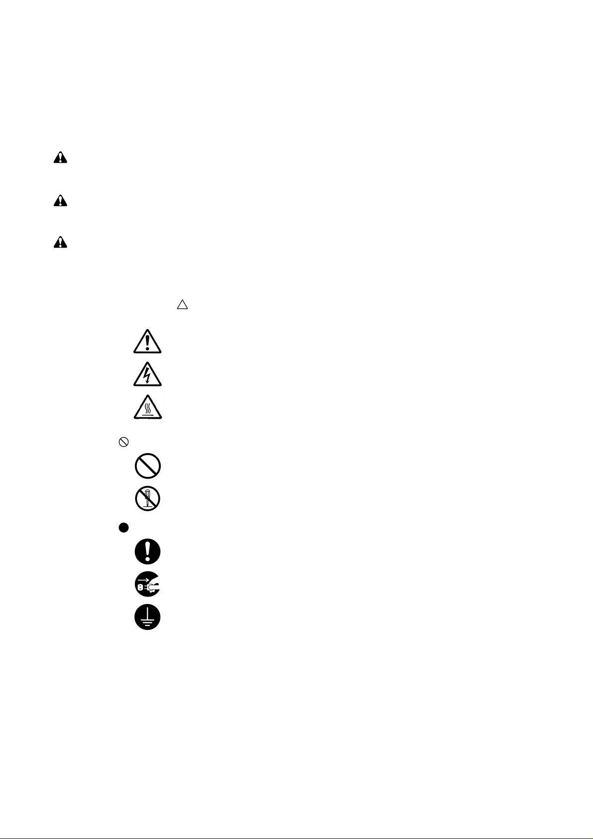
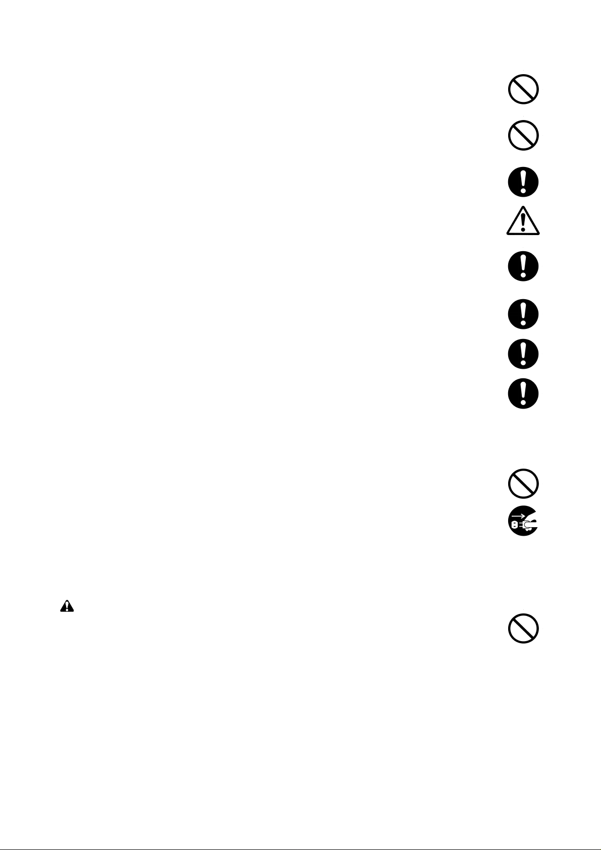
Symbols
The triangle ( ) symbol indicates a warning including danger and caution. The specific point
of attention is shown inside the symbol.
General warning.
Warning of risk of electric shock.
Warning of high temperature.
indicates a prohibited action. The specific prohibition is shown inside the symbol.
General prohibited action.
Disassembly prohibited.
indicates that action is required. The specific action required is shown inside the symbol.
General action required.
Remove the power plug from the wall outlet.
Always ground the printer.
Page 5
1. Installation Precautions
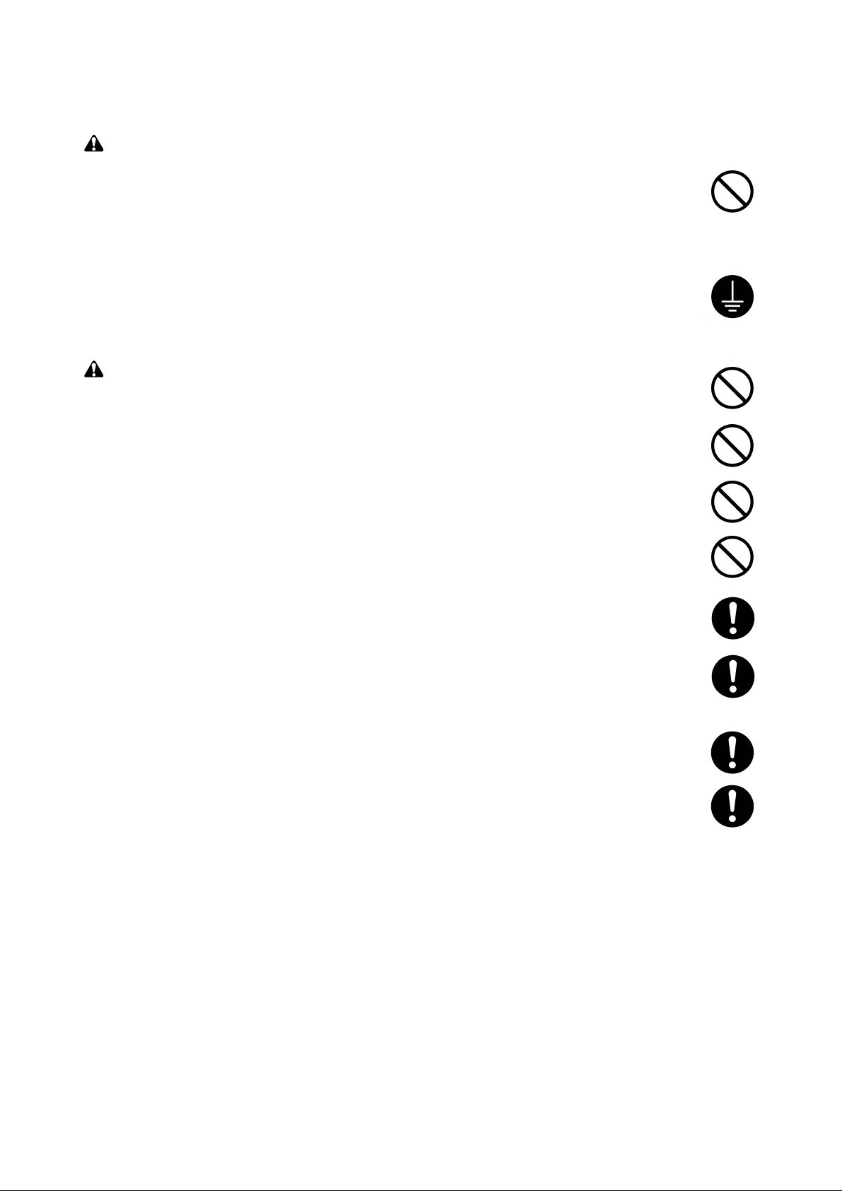
WARNING
• Do not use a power supply with a voltage other than that specified. Avoid multiple connections to
one outlet: they may cause fire or electric shock. When using an extension cable, always check
that it is adequate for the rated current. ............................................................................................
• Connect the ground wire to a suitable grounding point. Not grounding the printer may cause fire or
electric shock. Connecting the earth wire to an object not approved for the purpose may cause
explosion or electric shock. Never connect the ground cable to any of the following: gas pipes,
lightning rods, ground cables for telephone lines and water pipes or faucets not approved by the
proper authorities. .............................................................................................................................
CAUTION:
• Do not place the printer on an infirm or angled surface: the printer may tip over, causing injury. ....
• Do not install the printer in a humid or dusty place. This may cause fire or electric shock. ..............
• Do not install the printer near a radiator, heater, other heat source or near flammable material.
This may cause fire...........................................................................................................................
• Allow sufficient space around the printer to allow the ventilation grills to keep the machine as cool
as possible. Insufficient ventilation may cause heat buildup and poor copying performance...........
• Always handle the machine by the correct locations when moving it. ..............................................
• Always use anti-toppling and locking devices on printers so equipped. Failure to do this may
cause the printer to move unexpectedly or topple, leading to injury. ................................................
• Avoid inhaling toner or developer excessively. Protect the eyes. If toner or developer is
accidentally ingested, drink a lot of water to dilute it in the stomach and obtain medical attention
immediately. If it gets into the eyes, rinse immediately with copious amounts of water and obtain
medical attention. ..............................................................................................................................
• Advice customers that they must always follow the safety warnings and precautions in the
printer’s instruction handbook. ..........................................................................................................
Page 6
2. Precautions for Maintenance
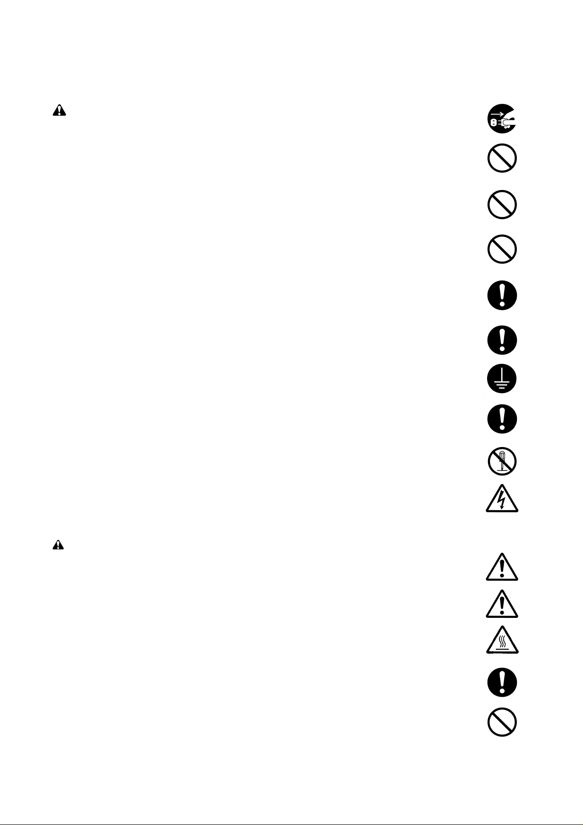
WARNING
• Always remove the power plug from the wall outlet before starting machine disassembly. .............
• Always follow the procedures for maintenance described in the service manual and other related
brochures. .........................................................................................................................................
• Under no circumstances attempt to bypass or disable safety features including safety
mechanisms and protective circuits. .................................................................................................
• Always use parts having the correct specifications...........................................................................
• Always use the thermostat or thermal fuse specified in the service manual or other related
brochure when replacing them. Using a piece of wire, for example, could lead to fire or other
serious accident. ...............................................................................................................................
• When the service manual or other serious brochure specifies a distance or gap for installation of a
part, always use the correct scale and measure carefully. ...............................................................
• Always check that the printer is correctly connected to an outlet with a ground connection. ...........
• Check that the power cable covering is free of damage. Check that the power plug is dust-free. If
it is dirty, clean it to remove the risk of fire or electric shock. ............................................................
• Never attempt to disassemble the optical unit in machines using lasers. Leaking laser light may
damage eyesight...............................................................................................................................
• Handle the charger sections with care. They are charged to high potentials and may cause
electric shock if handled improperly. .................................................................................................
CAUTION
• Wear safe clothing. If wearing loose clothing or accessories such as ties, make sure they are
safely secured so they will not be caught in rotating sections. .........................................................
• Use utmost caution when working on a powered machine. Keep away from chains and belts........
• Handle the fixing section with care to avoid burns as it can be extremely hot..................................
• Check that the fixing unit thermistor, heat and press rollers are clean. Dirt on them can cause
abnormally high temperatures. .........................................................................................................
• Do not remove the ozone filter, if any, from the printer except for routine replacement. ..................
Page 7
• Do not pull on the AC power cord or connector wires on high-voltage components when removing
them; always hold the plug itself. ......................................................................................................
• Do not route the power cable where it may be stood on or trapped. If necessary, protect it with a
cable cover or other appropriate item. ..............................................................................................
• Treat the ends of the wire carefully when installing a new charger wire to avoid electric leaks. ......
• Remove toner completely from electronic components. ...................................................................
• Run wire harnesses carefully so that wires will not be trapped or damaged. ...................................
• After maintenance, always check that all the parts, screws, connectors and wires that were
removed, have been refitted correctly. Special attention should be paid to any forgotten
connector, trapped wire and missing screws. ..................................................................................
• Check that all the caution labels that should be present on the machine according to the
instruction handbook are clean and not peeling. Replace with new ones if necessary. ...................
• Handle greases and solvents with care by following the instructions below:....................................
· Use only a small amount of solvent at a time, being careful not to spill. Wipe spills off completely.
· Ventilate the room well while using grease or solvents.
· Allow applied solvents to evaporate completely before refitting the covers or turning the main
switch on.
· Always wash hands afterwards.
• Never dispose of toner or toner bottles in fire. Toner may cause sparks when exposed directly to
fire in a furnace, etc. .........................................................................................................................
• Should smoke be seen coming from the printer, remove the power plug from the wall outlet
immediately.......................................................................................................................................
3. Miscellaneous
WARNING
• Never attempt to heat the drum or expose it to any organic solvents such as alcohol, other than
the specified refiner; it may generate toxic gas.................................................................................
Page 8

FS-8000C/CD/CN
CONTENTS
1-1 Specifications
1-1-1 Specifications ........................................................................................................................................... 1-1-2
1-1-2 Parts names and their functions............................................................................................................... 1-1-4
(1) Printer ............................................................................................................................................... 1-1-4
(2) Operation panel ................................................................................................................................ 1-1-5
1-1-3 Cross section view ................................................................................................................................... 1-1-6
1-2 Handling Precautions
1-2-1 Drum......................................................................................................................................................... 1-2-2
1-2-2 Developer and toner container ................................................................................................................. 1-2-2
1-2-3 Installation environment ........................................................................................................................... 1-2-2
1-3 Installation
1-3-1 Unpacking and installation ....................................................................................................................... 1-3-2
(1) Installation procedure........................................................................................................................ 1-3-2
1-4 Service Mode and Maintenance
1-4-1 Service mode ........................................................................................................................................... 1-4-2
(1) Executing service mode.................................................................................................................... 1-4-2
(2) Contents of service mode items........................................................................................................ 1-4-3
1-4-2 Maintenance............................................................................................................................................1-4-11
(1) Replacing the toner container ..........................................................................................................1-4-11
(2) Cleaning the main charger unit ....................................................................................................... 1-4-13
(3) Cleaning the printer......................................................................................................................... 1-4-16
(4) Replacing the oil roller unit.............................................................................................................. 1-4-20
(5) Cleaning the heat and press/heat rollers of paper dust .................................................................. 1-4-21
(6) Cleaning the fuser unit .................................................................................................................... 1-4-22
1-4-3 Downloading printer firmware for upgrade ............................................................................................. 1-4-23
(1) Format for the firmware files ........................................................................................................... 1-4-23
(2) Downloading firmware via the parallel interface ............................................................................. 1-4-24
(3) Downloading firmware using the memory card............................................................................... 1-4-25
(4) Downloading message data............................................................................................................ 1-4-27
1-5 Troubleshooting
1-5-1 Paper misfeed detection........................................................................................................................... 1-5-2
(1) Paper misfeed indication................................................................................................................... 1-5-2
(2) Paper misfeed detection sensors...................................................................................................... 1-5-3
1-5-2 Self-diagnosis........................................................................................................................................... 1-5-4
(1) Self-diagnostic function..................................................................................................................... 1-5-4
1-5-3 Image formation problems...................................................................................................................... 1-5-32
(1) No image appears (entirely white). ................................................................................................. 1-5-33
(2) No image appears (entirely black). ................................................................................................. 1-5-33
(3) Dirt on the top edge. ....................................................................................................................... 1-5-33
(4) Dirt on the back side. ...................................................................................................................... 1-5-34
(5) Image is too light............................................................................................................................. 1-5-34
(6) Background is visible. ..................................................................................................................... 1-5-34
(7) A white line appears longitudinally. ................................................................................................. 1-5-35
(8) A line appears longitudinally............................................................................................................ 1-5-35
(9) Oily streaks (15 cm intervals) appears at the top of the page longitudinally................................... 1-5-35
(10) A line appears laterally. ................................................................................................................. 1-5-36
1-1-1
Page 9

FS-8000C/CD/CN
(11) One side of the print image is darker than the other. .................................................................... 1-5-36
(12) Dots appear on the image............................................................................................................. 1-5-36
(13) The leading edge of the image is misaligned with the original image........................................... 1-5-37
(14) Paper creases............................................................................................................................... 1-5-37
(15) Offset occurs................................................................................................................................. 1-5-37
(16) Image is partly missing. ................................................................................................................ 1-5-38
(17) Fusing is poor................................................................................................................................ 1-5-38
(18) Dragged dirt lines appears............................................................................................................ 1-5-38
1-6 Assembly and Disassembly
1-6-1 Precautions for assembly and disassembly ............................................................................................. 1-6-2
(1) Precautions ....................................................................................................................................... 1-6-2
1-6-2 Paper feed section ................................................................................................................................... 1-6-3
(1) Detaching and refitting the MP tray unit............................................................................................ 1-6-3
(2) Detaching and refitting the MP tray feed roller and MP tray retard roller .......................................... 1-6-4
(3) Detaching and refitting the face-down unit........................................................................................ 1-6-5
(4) Detaching and refitting drive assembly B.......................................................................................... 1-6-6
(5) Detaching and refitting drive assembly A.......................................................................................... 1-6-6
(6) Detaching and refitting the paper conveying belts ............................................................................ 1-6-7
(7) Detaching and refitting the paper conveying fan motors 1 and 2...................................................... 1-6-8
(8) Detaching and refitting the upper and lower registration rollers........................................................ 1-6-9
(9) Detaching and refitting the middle roller ......................................................................................... 1-6-10
1-6-3 Laser scanner unit...................................................................................................................................1-6-11
(1) Detaching and refitting the laser scanner unit..................................................................................1-6-11
1-6-4 Main charger unit.................................................................................................................................... 1-6-13
(1) Detaching and refitting the main charger unit ................................................................................. 1-6-13
(2) Detaching and refitting the main charger grid ................................................................................. 1-6-13
1-6-5 Drum unit................................................................................................................................................ 1-6-14
(1) Detaching and refitting the drum unit .............................................................................................. 1-6-14
1-6-6 Primary transfer unit ............................................................................................................................... 1-6-15
(1) Detaching and refitting the primary transfer unit ............................................................................. 1-6-15
(2) Detaching and refitting the cleaning brush unit............................................................................... 1-6-15
1-6-7 Developers (and toner feed section) ...................................................................................................... 1-6-16
(1) Detaching and refitting the developers ........................................................................................... 1-6-16
(2) Detaching and refitting the waste toner duct assembly .................................................................. 1-6-18
(3) Detaching and refitting the black toner feed assembly ................................................................... 1-6-19
(4) Detaching and refitting the black toner container feed assembly ................................................... 1-6-19
(5) Detaching and refitting the black toner feed drive assembly .......................................................... 1-6-20
1-6-8 Secondary transfer unit .......................................................................................................................... 1-6-21
(1) Detaching and refitting the transfer roller and the separation charger unit ..................................... 1-6-21
(2) Detaching and refitting the secondary transfer unit shift clutch ...................................................... 1-6-23
1-6-9 Fuser unit (and drive section)................................................................................................................. 1-6-24
(1) Detaching and refitting the fuser unit .............................................................................................. 1-6-24
(2) Detaching and refitting the fuser top cover and upper separator bracket ....................................... 1-6-24
(3) Detaching and refitting the upper and lower fuser thermistors ....................................................... 1-6-26
(4) Detaching and refitting the upper and lower thermostats ............................................................... 1-6-28
(5) Detaching and refitting the upper and lower heater lamps ............................................................. 1-6-29
(6) Detaching and refitting the heat roller and the press/heat roller ..................................................... 1-6-30
(7) Detaching and refitting the separators of lower separator bracket ................................................. 1-6-34
(8) Detaching and refitting drive assembly C ....................................................................................... 1-6-35
1-6-10 PWBs and high voltage units ............................................................................................................... 1-6-36
(1) Detaching and refitting the main controller PWB ............................................................................ 1-6-36
1-1-2
Page 10

FS-8000C/CD/CN
(2) Detaching and refitting the engine controller PWB ......................................................................... 1-6-37
(3) Detaching and refitting the power supply unit ................................................................................. 1-6-38
(4) Detaching and refitting the developing/cleaning brush bias high voltage unit ................................ 1-6-40
(5) Detaching and refitting the main charger high voltage unit............................................................. 1-6-41
(6) Detaching and refitting the separation charger high voltage unit.................................................... 1-6-42
(7) Detaching and refitting the paper feeder/options relay PWB .......................................................... 1-6-44
(8) Detaching and refitting the transfer roller bias high voltage unit ..................................................... 1-6-44
1-6-11 Others................................................................................................................................................... 1-6-45
(1) Detaching and refitting the ozone filter ........................................................................................... 1-6-45
2-1 Mechanical Construction
2-1-1 Paper feed unit and secondary transfer unit ............................................................................................ 2-1-2
(1) Paper feed unit.................................................................................................................................. 2-1-2
(2) Secondary transfer unit..................................................................................................................... 2-1-5
2-1-2 MP tray unit .............................................................................................................................................. 2-1-6
2-1-3 Laser scanner unit.................................................................................................................................... 2-1-8
2-1-4 Developer ............................................................................................................................................... 2-1-10
(1) Y ellow developer..............................................................................................................................2-1-11
(2) Magenta developer ......................................................................................................................... 2-1-14
(3) Cyan developer............................................................................................................................... 2-1-17
(4) Black developer .............................................................................................................................. 2-1-20
(5) Transition of toner for development ................................................................................................ 2-1-24
2-1-5 Drum unit and main charger unit ............................................................................................................ 2-1-25
(1) Drum unit ........................................................................................................................................ 2-1-25
(2) Main charger unit ............................................................................................................................ 2-1-29
2-1-6 Primary transfer unit ............................................................................................................................... 2-1-30
(1) Primary transfer unit....................................................................................................................... 2-1-30
(2) Cleaning brush unit ......................................................................................................................... 2-1-30
2-1-7 Fuser unit ............................................................................................................................................... 2-1-35
2-1-8 Face-down tray unit................................................................................................................................ 2-1-38
2-2 Electrical Parts Layout
2-2-1 Electrical parts layout ............................................................................................................................... 2-2-2
(1) Main frame, Face-down unit, and MP tray unit ................................................................................. 2-2-2
(2) Developers, drum unit and main charger unit ................................................................................... 2-2-3
(3) Primary transfer, secondary transfer, paper feed, and fuser units .................................................... 2-2-5
(4) Main frame rear and controller box ................................................................................................... 2-2-6
2-3 PWB Operation and Connector Signal Assignment
2-3-1 Engine controller PWB [KP-801] .............................................................................................................. 2-3-2
2-3-2 Main controller PWB [KP-800].................................................................................................................2-3-11
2-4 Appendixes
Connection diagram........................................................................................................................................... 2-4-2
Maintenance kits................................................................................................................................................ 2-4-3
Periodic maintenance procedures ..................................................................................................................... 2-4-4
1-1-3
Page 11

Chapter I
Page 12

CONTENTS
1-1 Specifications....................................................................................1-1-2
1-1-1 Specifications ........................................................................................................................................... 1-1-2
1-1-2 Parts names and their functions............................................................................................................... 1-1-4
(1) Printer ............................................................................................................................................... 1-1-4
(2) Operation panel ................................................................................................................................ 1-1-5
1-1-3 Cross section view ................................................................................................................................... 1-1-6
Page 13

FS-8000C/CD/CN
1-1-1 Specifications
Type ............................................... Console type color laser printer
Printing system...............................Electro photographic four colors (cyan, magenta, yellow, and black) printing. 4-cycle
intermediate transfer drum.
Paper..............................................Cassette: Plain paper (64 to 90 g/m
MP tray: Plain paper (64 to 90 g/m
Special paper: Transparencies, tracing paper, colored paper, letterhead and
envelopes
Note: Use the MP tray for special paper.
Printing sizes.................................. Maximum: A3/Ledger
1
Minimum: A6R /5
/2" × 81/2"/Folio (When the MP tray is used.)
Print speed ..................................... A4: 8 pages/30 pages per min. [Color/Monochrome]
A4-R*: 4 pages/15 pages per min. [Color/Monochrome]
A5: 8 pages/15 pages per min. [Color/Monochrome]
B5: 4 pages/15 pages per min. [Color/Monochrome]
A3: 4 pages/15 pages per min. [Color/Monochrome]
Letter: 8 pages/30 pages per min. [Color/Monochrome]
Letter-R*: 4 pages/15 pages per min. [Color/Monochrome]
Legal: 4 pages/15 pages per min. [Color/Monochrome]
Note (*): MP tray only
First copy time................................ 28 s/17 s [Color/Monochrome]
Note: A4, Ecopower mode off, room temperature 23° C/73.4 °F, 60 % RH
Warm-up time.................................Approximately 300 s or less (room temperature 23° C/73.4 °F, 60 % RH)
Paper feed system ......................... FS-8000C/CN model: Paper feeder PF-30A (2 universal type cassettes) and MP
(Multi purpose) tray
FS-8000CD model: Duplex unit PD-30 (1 universal type cassette) and MP (Multi
purpose) tray
Paper loading capacity................... Cassette: 500 sheets (80 g/m
MP (Multi purpose) tray: 150 sheets (80 g/m
Printout stacking capacity .............. Face-down tray: 500 sheets with paper full sensor
Face-up tray: 150 sheets (80 g/m2, 0.11 mm)
Photoconductor .............................. aSi drum (diameter 80 mm)
Charging system ............................ Single positive corona charging
Exposure light source .................... Semiconductor laser
Exposure scanning system ............ Polygon mirror
Developing system......................... Dry, reverse developing (magnetic brush)
Developer: 2-component
Toner density control: T/C sensor
Toner replenishing: automatic from the toner container
Transfer system .............................Primary: Intermediate transfer drum (diameter 160 mm)
Secondary: Transfer roller
Separation system .........................AC corona separation charging
Fixing system ................................. Heat roller and press/heat roller (soft type, diameter 45 mm)
Heat source: 2 halogen heaters (500 W)
Control temperature: 185 °C/365 °F (at normal ambient temperature)
Abnormally high temperature protection device: thermostats
Charge erasing system .................. Exposure by eraser lamp (LED array)
Cleaning system ............................Drum: Cleaning blade
Primary (intermediate) transfer drum: Fur brush
Controller hardware .......................CPU: Power PC750CX 400 MHz
Code ROM: 8 MB (2 system DIMM PWBs in sockets)
Font ROM: 4 MB (PCL and KPDL)
Main RAM: 64 MB (standard)
Option expansion RAM: 2 sockets (Maximum 256 MB, including the standard RAM)
Option memory card: 1 slot (CompactFlash card)
Option interface*: 2 slots (KUIO LV)
Note (*): A network interface card is standard-installed with FS-8000CN.
2
)
2
), Thick paper (90 to 220 g/m2)
2
, 0.11 mm)
2
, 0.11 mm)
1-1-2
Page 14

FS-8000C/CD/CN
Host computer interface................. Parallel: Bi-directional parallel (IEEE 1284 Nibble/ECP mode)
Serial: RS-232C, 115.2 kbps maximum
Option: KUIO 2 slots
Controller software .........................Emulation: PCL 5C, KPDL, KCGL
Fonts: PCL, PS, PRESCRIBE
Smoothing ...................................... KIR (monochrome mode only)
Toner saving...................................EcoPrint mode (monochrome mode only)
Resolution ...................................... 600 × 600 dpi
Dimensions ....................................Printer main unit: 590 × 585 × 429 mm (W × D × H)
1
/4" × 235/16" × 167/8" (W × D × H)
23
Paper feeder PF-30A: 560 × 566 × 251mm (W × D × H)
223/8" × 221/4" × 97/8" (W × D × H)
Duplex unit PD-30: 560 × 566 × 251 mm (W × D × H)
223/8" × 221/4" × 97/8" (W × D × H)
Weight ............................................ Printer main unit: 76.3 kg/167.86 lbs (including toner containers and oil roller unit)
Paper feeder PF-30A: 19.1 kg/40.02 lbs
Duplex unit PD-30: 22.1 kg/48.62 lbs
Floor requirements ......................... 891× 560 mm (W × D)
1
/16" × 221/16" (W × D)
35
Functions........................................Self-diagnostics, sleep mode (energy saving)
Power source ................................. 120 V AC, 60 Hz, 11.5 A
220 – 240 V AC, 50/60 Hz, 5.8 A
Power consumption ....................... Maximum: 1318 W (120 V), 1323 W (220 – 240 V)
Printing: 412 W (120 V), 437 W (220 – 240 V)
Ready: 177 W (120 V), 184 W (220 – 240 V)
Sleep mode: 34 W/37 W* (120 V), 35 W/38 W* (220 – 240 V)
Note (*): Network model
Options...........................................Expansion DIMM (32/64/128 MB), memory card, network interface card IB-20/IB-21/
IB-21E, hard disk unit, paper feeder PF-30A, duplex unit PD-30*, mailbox sorter SO-
30, document finisher DF-31, bulk stacker ST-30, barcode reader BC-1, caster CA-
31, caster kit CA-31B
Note (*): Optional for FS-8000C/CN models.
1-1-3
Page 15

FS-8000C/CD/CN
1-1-2 Parts names and their functions
(1) Printer
6
2
3
4
5
7
°
1
8
·
(
‚
9
*
&
^
%
Figure 1-1-1
0
#
!
@
)
¤
$
⁄
‹
›
‡
fl
fi
1-1-4
1 Side cover
2 Face-down tray
3 Cyan toner container
4 Magenta toner container
5 Yellow toner container
6 Paper stopper
7 Main charger unit
8 Black toner container
9 Waste toner bottle
0 Primary transfer unit
! Release lever
@ Secondary transfer unit (transfer roller
and separation charger unit)
# Separation charger wire cleaner
$ Paper feed unit
% Fuser unit
^ Front cover
& Oil roller unit
Cautions:
The power cord must keep plugged from power at least 30 minutes since the power switch is turned off.
In case the power plug must be unplugged immediately after power-off for service purpose, pull out the
paper feed unit so that the fuser unit is away from developers to avoid toner lumping due to the heat from
the fuser unit.
* Left paper guide
( Face-up tray
) MP tray
⁄ Parallel interface connector
¤ Paper feeder/duplex unit side cover
‹ Serial interface connector
› Memory card slot
fi Network interface card*
fl Hard disk unit*
‡ Filter duct
Power switch
· Power cord connector
‚ Paper feeder*3 or duplex unit*
*1: Standard-installed with FS-8000CN model only
2
: Option
*
3
: Standard-installed with FS-8000C model
*
4
*
: Standard-installed with FS-8000CD model
2
or Network interface card*2 slot [OPT2/HDD]
1
slot [OPT1]
4
Page 16
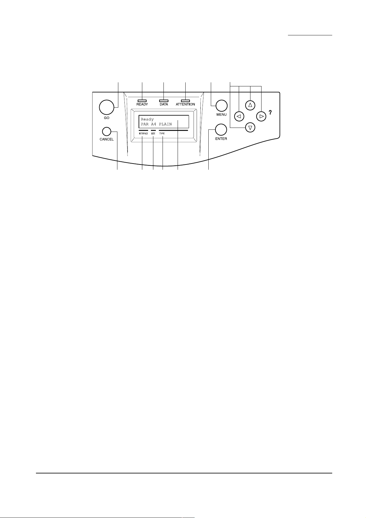
(2) Operation panel
FS-8000C/CD/CN
31678 5
02!@ 9 4
Figure 1-1-2
1 Go key (GO)
2 Cancel key (CANCEL)
3 Menu keys (MENU)
4 Enter key (ENTER)
5 Arrow keys
6 Ready indicator (READY)
7 Data indicator (DATA)
8 Attention indicator (ATTENTION)
9 Message display
0 Interface indicator (INTERFACE)
! Paper size indicator (SIZE)
@ Paper type indicator (TYPE)
1-1-5
Page 17
FS-8000C/CD/CN
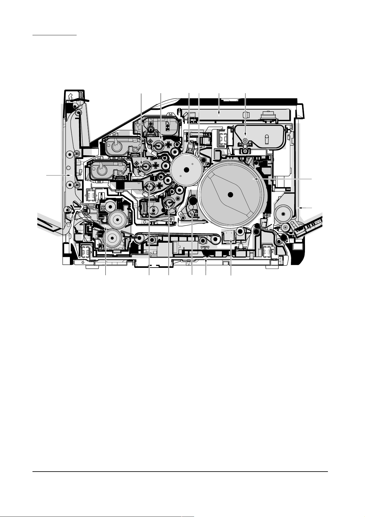
1-1-3 Cross section view
%
7
6
4
5
3
0
!
1
$ 298
Figure 1-1-3 Cross section view
1 MP tray unit
2 Paper feed unit
3 Laser scanner unit
4 Main charger unit
5 Drum unit
6 Yellow developer and yellow toner container
7 Magenta developer and magenta toner container
8 Cyan developer and cyan toner container
9 Black developer
0 Black toner container
! Primary transfer unit
@ Cleaning brush unit
# Secondary transfer unit
$ Fuser unit
% Face-down unit
@
#
1-1-6
Page 18

CONTENTS
1-2 Handling Precautions .......................................................................1-2-2
1-2-1 Drum......................................................................................................................................................... 1-2-2
1-2-2 Developer and toner container ................................................................................................................. 1-2-2
1-2-3 Installation environment ........................................................................................................................... 1-2-2
Page 19
1-2 Handling precautions
FS-8000C/CD/CN
1-2-1 Drum
Note the following when handling or storing the drum.
• Keep the drum at an ambient temperature between –20°C/–4°F and 40°C/104°F and at a relative
humidity not higher than 85 % RH. Avoid abrupt changes in temperature and humidity.
• Avoid exposure to any substance which is harmful to or may affect the quality of the drum.
• Do not touch the drum surface with any object. Should it be touched by hands or stained with oil, clean it.
1-2-2 Developer and toner container
Store the developer and toner container in a cool, dark place. Avoid direct light and high humidity.
1-2-3 Installation environment
1.Temperature: 10 - 32.5°C/50 - 90.5°F
2.Humidity: 15 - 80 %RH
3.Power supply: 120 V AC ±10 %, 11.5 A
4.Power source frequency: 50 Hz ±0.2 %/60 Hz ±0.2 %
5.Installation location
• Avoid direct sunlight or bright lighting.
• Avoid extremes of temperature and humidity, abrupt ambient temperature changes, and hot or cold air directed onto
the machine.
• Avoid dust and vibration.
• Choose a surface capable of supporting the weight of the machine.
• Place the machine on a level surface (maximum allowance inclination: 1° ).
• Avoid air-borne substances that may adversely affect the machine or degrade the photoconductor, such as
mercury, acidic of alkaline vapors, inorganic gasses, NOx, SOx gases, and chlorine-based organic solvents.
• Select a room with good ventilation.
6.Allow sufficient access for proper operation and maintenance of the machine.
Machine front: 600 mm/23
Machine right: 500 mm/19
220 - 240 V AC 10 %, 5.8 A
5
/8" Machine rear: 300 mm/1113/16"
11
/16" Machine left: 500 mm/1911/16"
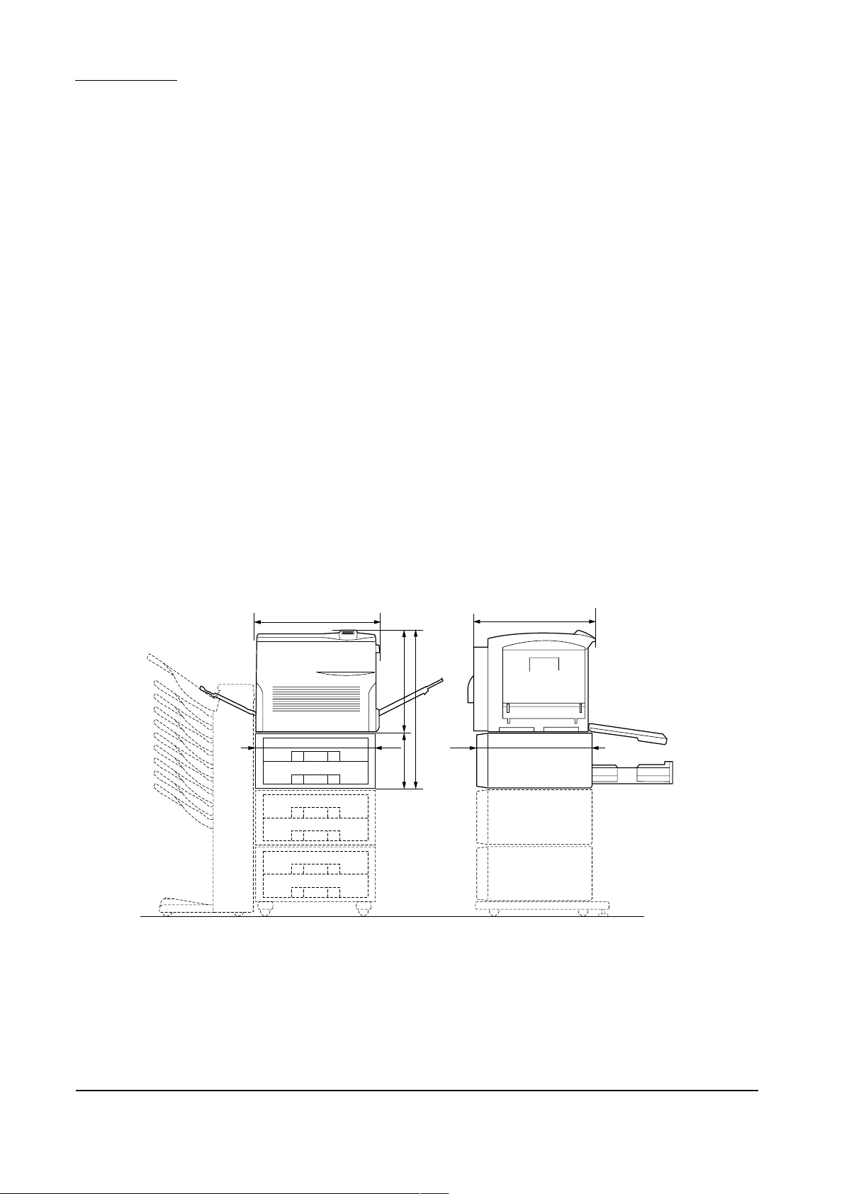
a
1
a: 590 mm/23
b: 585 mm/23
c: 680 mm26
/4"
5
/16"
3
/4"
d: 429 mm/167/8"
d
c
ef
g
e: 560 mm/22
f: 566 mm/22
g: 251 mm/9
b
3
/8"
1
/4"
7
/8"
1-2-2
Figure 1-2-1 Installation dimensions
Page 20

CONTENTS
1-3 Installation .........................................................................................1-3-2
1-3-1 Unpacking and installation ....................................................................................................................... 1-3-2
(1) Installation procedure........................................................................................................................ 1-3-2
Page 21
1-3 Installation
FS-8000C/CD/CN
1-3-1 Unpacking and installation
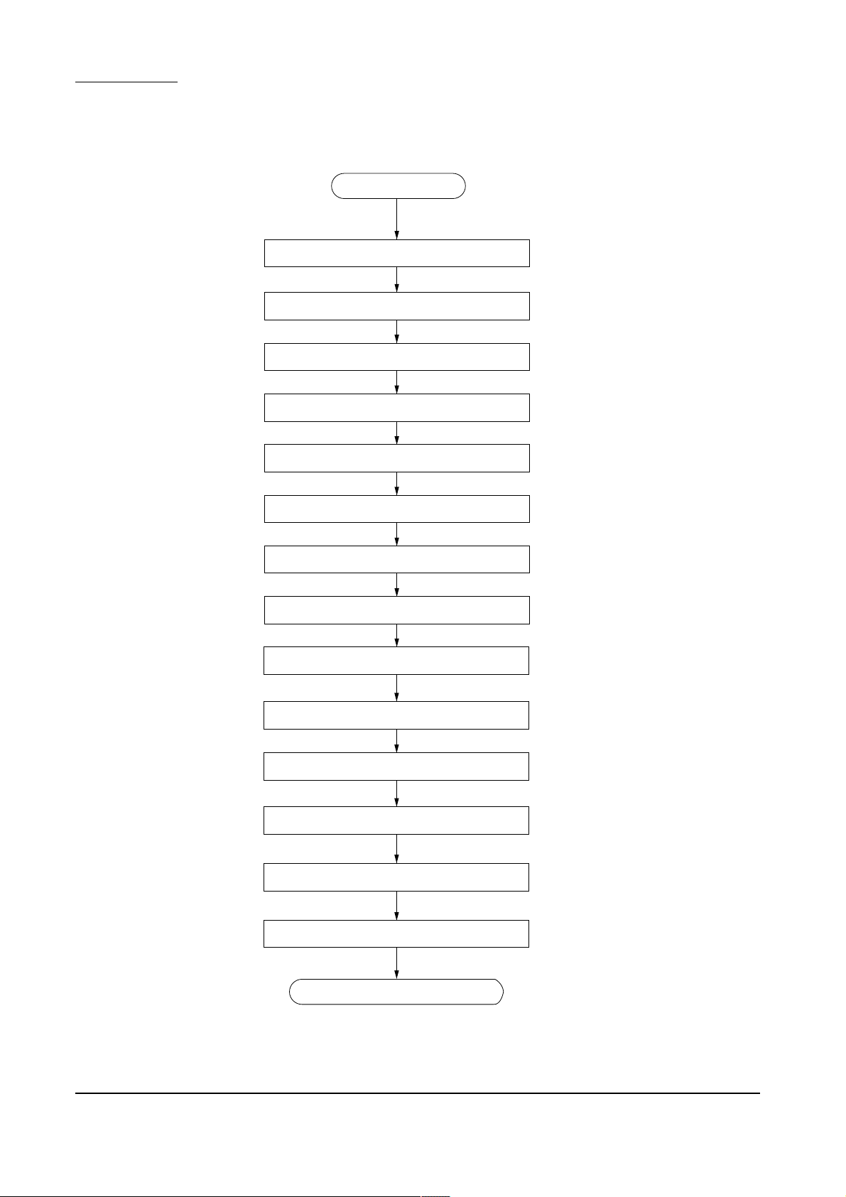
(1) Installation procedure
Attaching the casters (purchased separately)
Joining the printer and the paper feeder(s)
Start
Unpacking
Removing the tape
Attaching the accessories
Placing the printer in a proper location
Installing the fuser unit and the oil roller unit
Securing the heat and press/heat rollers
Installing the secondary transfer unit
Installing the waste toner bottle
Installing the four developers
Installing the toner containers
1-3-2
Making connectors to the computer
Printing a status page for test
Completion of the machine installation
Page 22
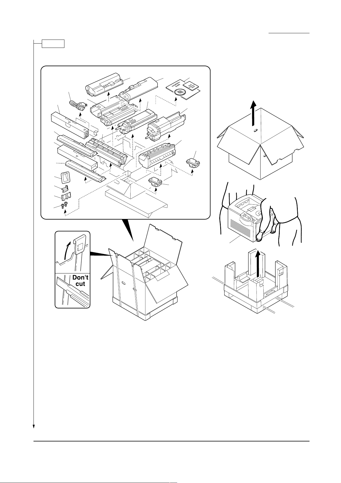
Unpack.
• Printer
LS-8000C/CD/CN
7
!
^
&
*
(
8
@
%
3
6
9
4
0
2
5
#
$
$
Figure 1-3-1 Unpacking (Printer)
1 Printer
2 Documents (Installation guide,
Quick reference guide, and
CD-ROM)
3 Cyan developer
4 Magenta developer
5 Yellow developer
6 Black developer
7 Cyan toner container
8 Magenta toner container
9 Yellow toner container
1
0 Black toner container
! Secondary transfer unit
@ Oil roller unit
# Fuser unit
$ Waste toner bottles
% Power cord
^ Filter duct
& Joint jig
* Quick reference guide holder
( Screws (Two)
Warning:
Lift the printer by more than two persons. The printer weighs approx. 76 kg.
1-3-3
Page 23
FS-8000C/CD/CN
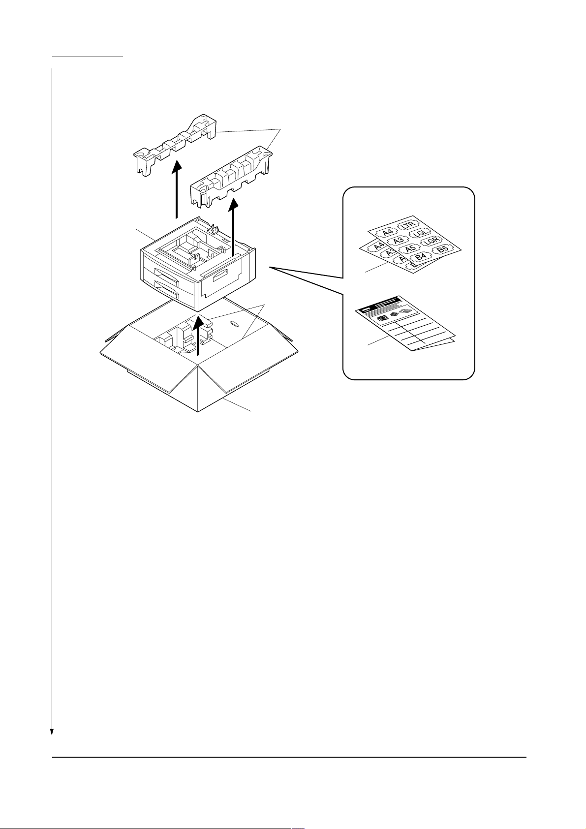
• Paper feeder (or duplex unit)
1
4
3
4
2
5
Figure 1-3-2 Unpacking the paper feeder (or duplex unit)
1 Paper feeder (or duplex unit)
2 Installation manual
3 Paper size indication plate
4 Pads
5 Packing case
Warning:
The paper feeder (duplex unit) weighs approx.19 kg (22 kg).
1-3-4
Page 24
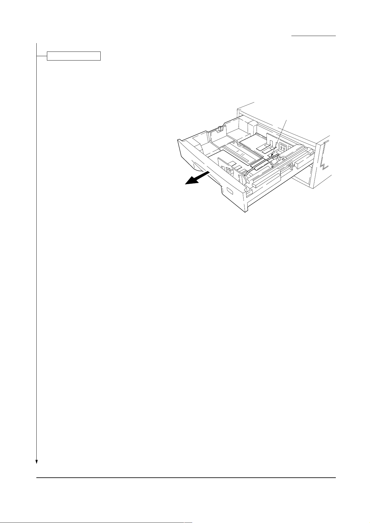
Removing the tape
1. Draw the upper and lower paper cassettes and
then remove the transportation tape.
LS-8000C/CD/CN
Tape
Figure 1-3-3
1-3-5
Page 25
FS-8000C/CD/CN
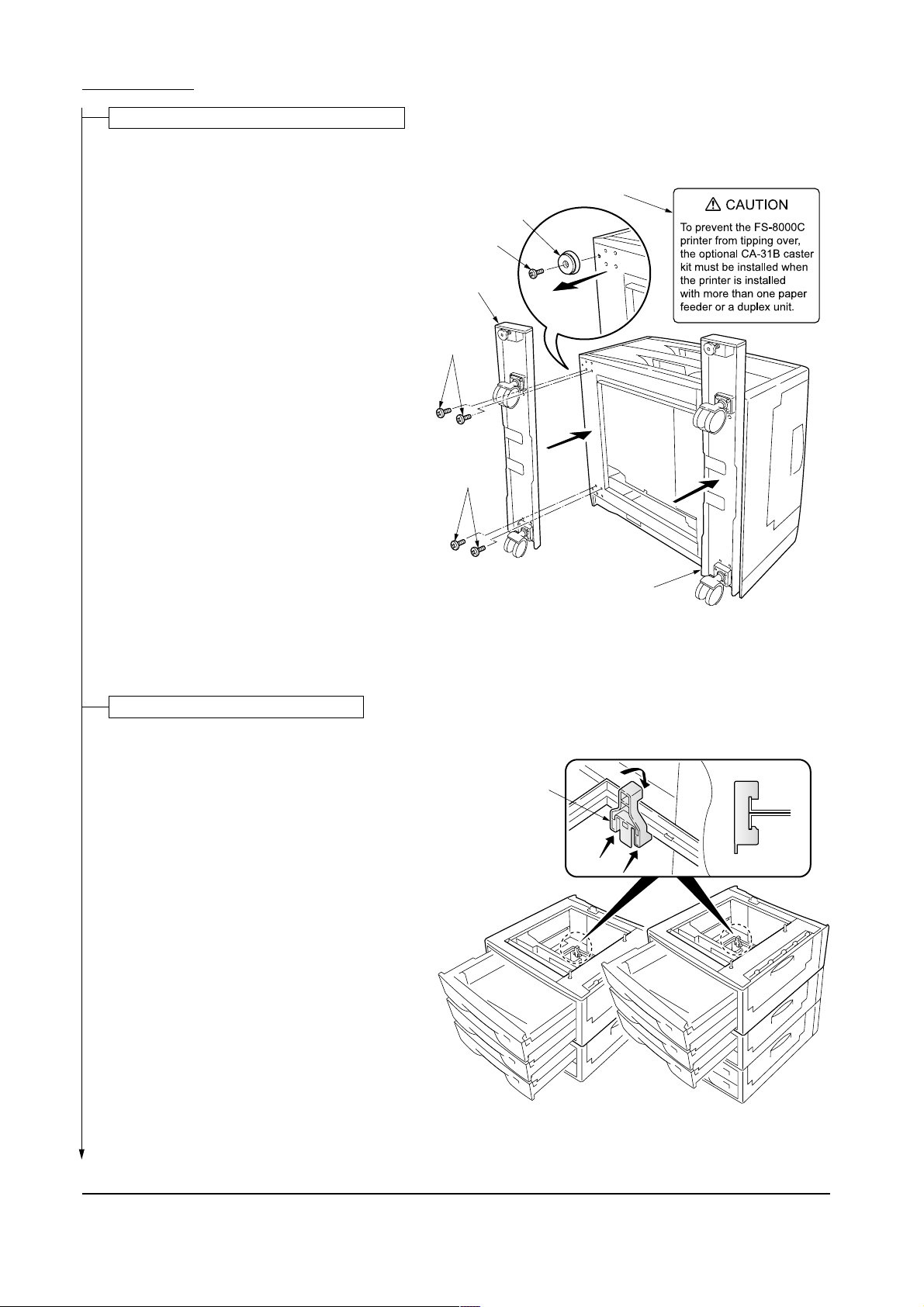
Attaching the casters (purchased separately)
Caution
To prevent the printer from tipping over because
of weight of the printer and the upper paper
drawers, the CA-31B caster kit must be installed
at the bottom-most paper feeder, when an
optional paper feeder or duplex unit is installed
with the printer.
Caution labels have been attached to the paper
feeder and the duplex unit.
Caution label
Foot
Screw
Caster base
1. Stand the paper feeder with the rear side on the
floor.
2. Remove each one screw to remove four feet.
3. Install two optional caster bases onto the bottom
of the paper feeder by using four screws for
each. Be sure to face the longer end towards the
front of the paper feeder.
Joining the printer and paper feeder(s)
1. Using the topple-resistant bracket (supplied with
the caster kit CA-31B), stack and join the bottom
and middle paper feeders.
2. Place the printer on top of the paper feeders (by
more than two persons).
Screws
Screws
Caster base
Figure 1-3-4
Side view
Topple-resistant
bracket
1-3-6
Figure 1-3-5
Page 26
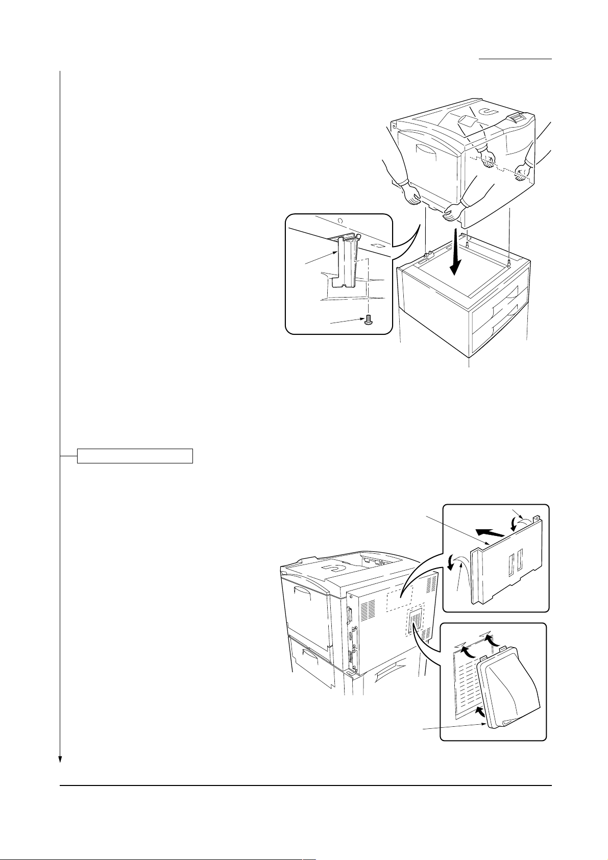
3. Join the printer and topmost paper feeder with
the joint jig provided using one screw.
Warning:
Lift the printer by more than two persons. The printer
weighs approx. 76 kg.
LS-8000C/CD/CN
Joint jig
Screw
Attaching the accessories
1. Install the filter duct.
2. Install the quick reference guide holder. Peel the
protective tape off from the holder when attaching
the holder.
Figure 1-3-6
Quick reference guide holder
Tape
Tape
Filter duct
Figure 1-3-7
1-3-7
Page 27
FS-8000C/CD/CN
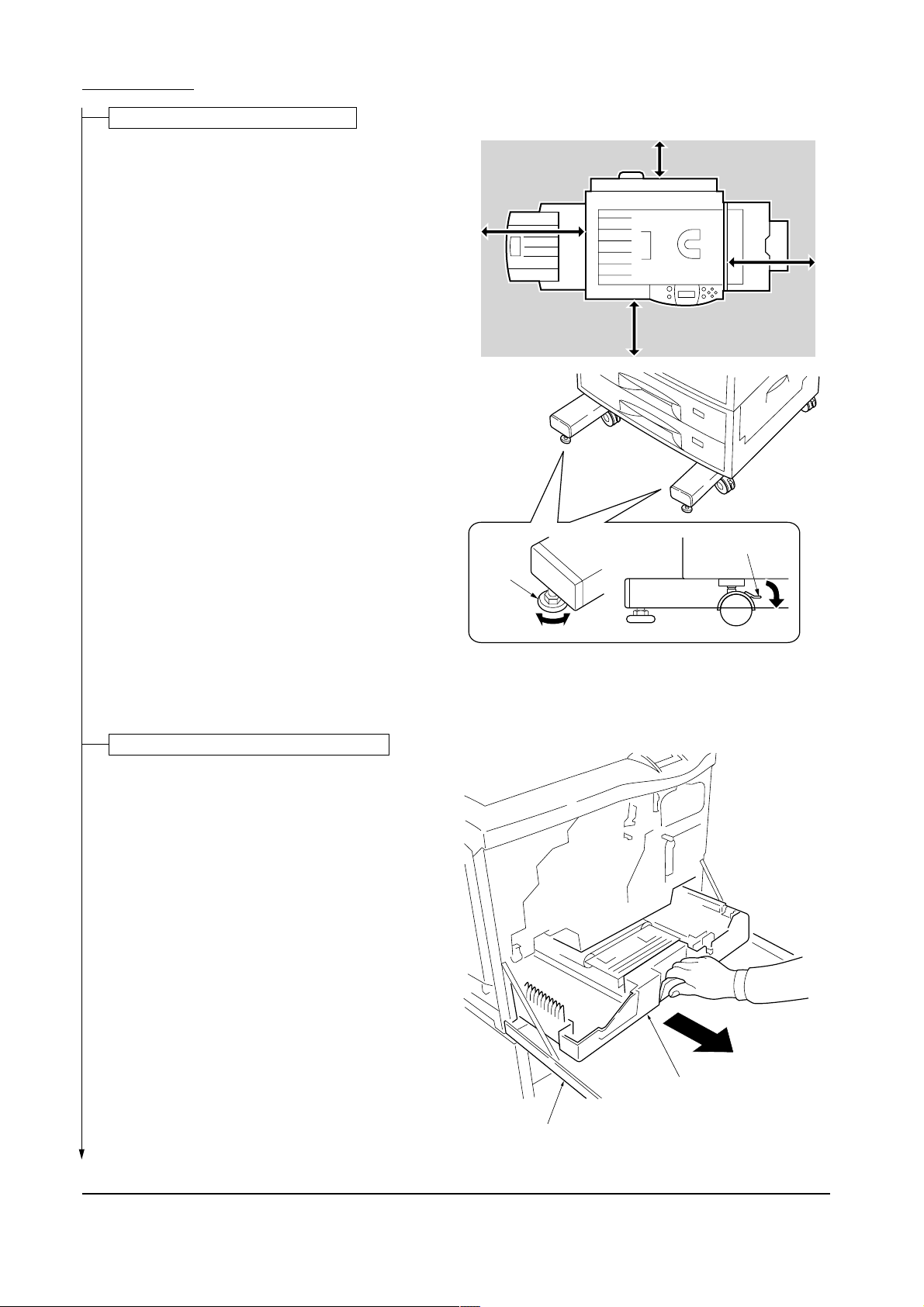
Placing the printer in a proper location
1. Place the paper feeder in a proper location.
2. Lock the stopper for each caster and turn the
height adjuster clockwise until the adjuster
reaches the floor. This fixes the printer in place.
Left: 50 cm
(19-11/16 inches)
Front: 60cm
(23-5/8 inches)
Height
adjuster
Rear: 30cm
(11-13/16 inches)
Right: 50cm
(19-11/16 inches)
Stopper
Installing the fuser unit and the oil roller unit
1. Open the front cover.
2. Pull out thoroughly the paper feed unit.
Figure 1-3-8
Paper feed unit
1-3-8
Front cover
Figure 1-3-9
Page 28
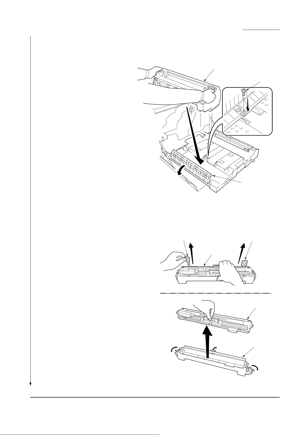
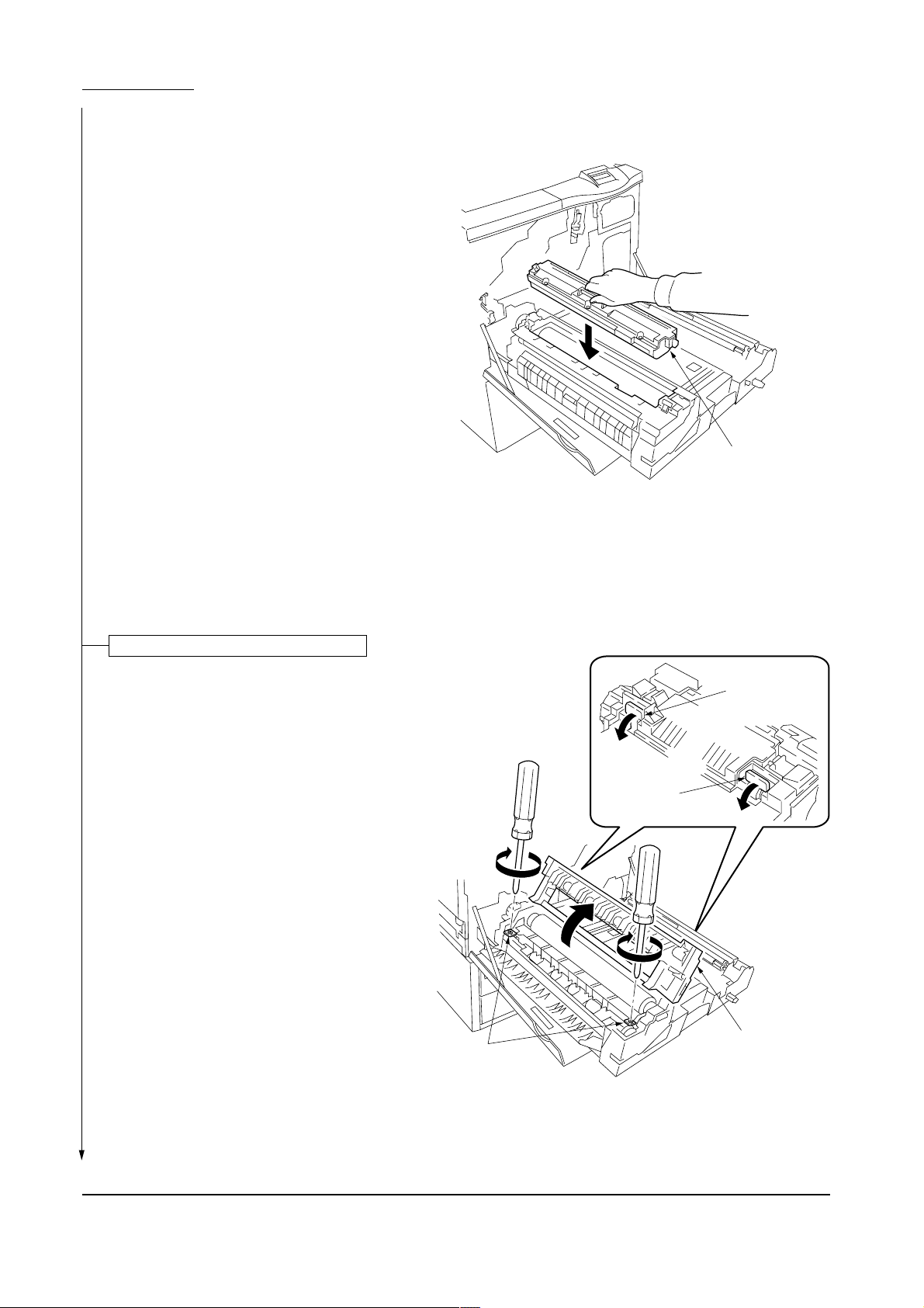
3. Open the left paper guide by pulling down the
green-colored handle.
4. Insert the fuser unit onto the paper feed unit.
5. Secure the fuser unit with the screw.
LS-8000C/CD/CN
Fuser unit
Screw
6. Remove the oil seal tapes at both ends of the oil
roller unit.
7. Take out the oil roller unit from the case.
Oil seal tape
Left paper guide
Figure 1-3-10
Oil seal tape
Oil roller unit
Oil roller unit
Figure 1-3-11
Case
1-3-9
Page 29
FS-8000C/CD/CN
8. Install the oil roller unit onto the fuser unit until it
is locked at both ends.
Oil roller unit
Figure 1-3-12
Securing the heat and press/heat rollers
The pressure between heat roller and press/heat
roller are kept released during transportation. Secure
the pressure by the following:
1. Open the fuser top cover by lowering the lock
buttons.
2. Firmly tighten two screws until they stop.
Screws
Lock button
Lock button
Fuser top cover
1-3-10
Figure 1-3-13
Page 30
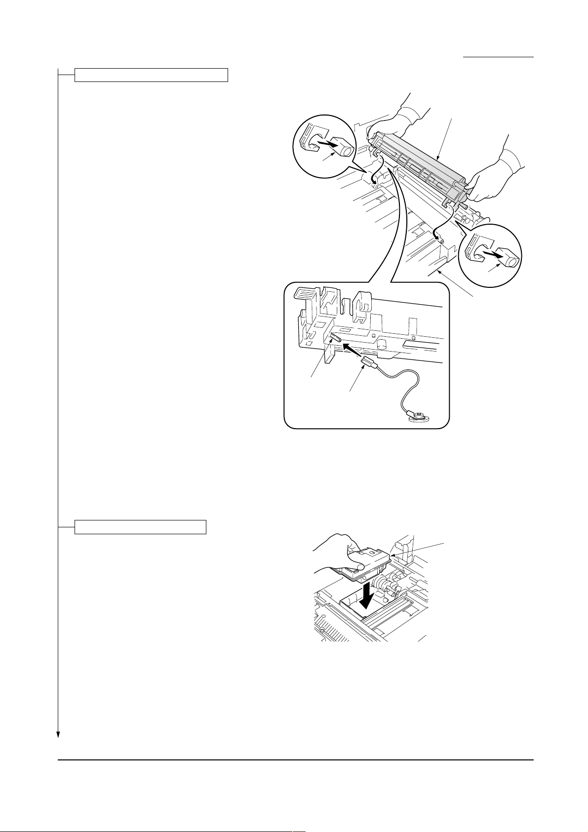
Installing the secondary transfer unit
1. Connect the tab from the paper feed unit to the
terminal of the secondary transfer unit.
2. Fit the fulcrums of secondary transfer unit on the
bushes and then put it on the paper feed unit.
LS-8000C/CD/CN
Secondary transfer unit
Bush
Bush
Paper feed unit
Installing the waste toner bottle
1. Install the waste toner bottle.
Terminal
Tab
Figure 1-3-14
Waste toner bottle
Figure 1-3-15
1-3-11
Page 31

FS-8000C/CD/CN
Installing the four developers
1. Remove one screw.
2. Remove the lock pin from the primary transer
unit.
3. Release the (green-colored) lock lever.
4. Draw the primary transfer until it stops.
5. While pushing the gray lever, pull out the
primary transfer unit.
6. Pull out the primary transfer unit from the
printer. Make sure not to scratch the round
surface, especially at its bottom.
7. Close the paper feed unit.
Gray Lever
Screw
Lock Lever
Lock pin
Primary transfer unit
8. Unscrew screws A and B. Free the two
stoppers.
9. Pull out the process frame.
Figure 1-3-16
Stopper
Screw B
Screw A
Screw A
Stopper
Screw B
1-3-12
Process frame
Figure 1-3-17
Page 32

LS-8000C/CD/CN
10. Detach the two tags.
11. Remove the front and rear stoppers.
Tag
Tag
Front stopper
Figure 1-3-18
Rear stopper
1-3-13
Page 33

FS-8000C/CD/CN
12. Peel off the tapes and then remove the
protective pad from each developer unit.
Developer
Tapes
Protective pad
Figure 1-3-19
1-3-14
Page 34

LS-8000C/CD/CN
13. Set each developer in its corresponding position
in the process frame.
Process frame
Black developer
Developing roller
Cyan developer
Magenta developer
Yellow developer
Figure 1-3-20
1-3-15
Page 35

FS-8000C/CD/CN
14. Close the process frame and then lock the two
stoppers.
15. Fix two screws A first, and then fix two B screws.
Stopper
Screw B
Screw A
Screw A
Stopper
Screw B
16. Pull out the paper feed unit.
17. Replace the primary transfer unit.
18. Close the lock lever.
19. Close the paper feed unit.
20. Secure the screw.
Process frame
Figure 1-3-21
Primary transfer unit
Screw
1-3-16
Lock lever
Paper feed unit
Figure 1-3-22
Page 36

Installing the toner containers
1. Shake each toner container well before use.
2. Install the four toner containers into their
corresponding developers.
3. Close the front cover.
LS-8000C/CD/CN
Toner container
Black
Yellow
Magenta
Cyan
Front cover
Making connections to the computer
1. Connect the printer cable to the printer parallel
connector. Connect the other end to the
computer.
NOTE: To install the network interface card for
connecting the printer to the network, refer to the
documentation supplied with the network
interface card. (Standard-installed with FS8000CN model only.)
2. Connect the power cord to the printer power inlet.
Figure 1-3-23
Parallel interface connector
Network interface card
Figure 1-3-24
1-3-17
Page 37

FS-8000C/CD/CN
Printing a status page for test
1. Add paper in the paper cassette.
2. Connect the power cord to the power out
let.
3. Turn on the printer power switch, and then
wait until [Print Ready] is displayed.
4. Press the MENU key on the operation
panel.
5. Press the
Status page] is displayed.
6. Press the ENTER key twice. A status page
is printed.
Completion of the machine installation
key repeatedly until [Print
1-3-18
Page 38

CONTENTS
1-4 Service Mode and Maintenance
1-4-1 Service mode ........................................................................................................................................... 1-4-2
(1) Executing service mode.................................................................................................................... 1-4-2
(2) Contents of service mode items........................................................................................................ 1-4-3
1-4-2 Maintenance............................................................................................................................................1-4-11
(1) Replacing the toner container ..........................................................................................................1-4-11
(2) Cleaning the main charger unit ....................................................................................................... 1-4-13
(3) Cleaning the printer......................................................................................................................... 1-4-16
(4) Replacing the oil roller unit.............................................................................................................. 1-4-20
(5) Cleaning the heat and press/heat rollers of paper dust .................................................................. 1-4-21
(6) Cleaning the fuser unit .................................................................................................................... 1-4-22
1-4-3 Downloading printer firmware for upgrade ............................................................................................. 1-4-23
(1) Format for the firmware files ........................................................................................................... 1-4-23
(2) Downloading firmware via the parallel interface ............................................................................. 1-4-24
(3) Downloading firmware using the memory card............................................................................... 1-4-25
(4) Downloading message data............................................................................................................ 1-4-27
Page 39

1-4 Service mode and maintenance
FS-8000C/CD/CN
1-4-1 Service mode
The printer is equipped with the service mode that can be accessed in the menu system. The service mode is intended
for use by the service person for maintenance and service for the items explained in the following sections.
(1) Executing service mode
Message display
Ready
PAR A4 PLAIN
1 Press the MENU key.
Print
Menu Map
2 Press the or key several times
until [Others >] is displayed.
Print
Status page
To print a status page for the user information.
See the operation guide for details.
Others >
3 Press the key.
Service mode items
To scroll
these items,
press the
or key
repeatedly.
>MSG Language >
English
>Service >
>>Print
Status Page
>>Print
Test Page 1
>>Print
Test Page 2
>>Drum
>>Maintenance
[A]
>>Maintenance
[B]
>>Maintenance
[C]
4 Press the or key several times
until [>Service >] is displayed.
5 Press the key.
To print a status page for service purpose.
See page 1-4-3.
To print a test page, mode 1.
See page 1-4-7.
To print test pages, mode 2.
See page 1-4-7.
To performing a drum surface refreshing.
See page 1-4-8.
To reset the counter after replacing maintenance kit A.
See page 1-4-8.
To reset the counter after replacing maintenance kit B.
See page 1-4-9.
To reset the counter after replacing maintenance kit C.
See page 1-4-9.
1-4-2
>>Maintenance
[D]
To reset the counter after replacing maintenance kit D.
See page 1-4-10. Note: For countries other than European
countries and Australia.
Page 40

(2) Contents of service mode items
FS-8000C/CD/CN
DescriptionService items
>>Print
Status Page
Printing a status page for service purpose
Description
Service information on the status page include various information and settings for the printer,
including service statistics, etc.
Purpose
To understand the machine environments and general settings.
Procedure
Enter the service mode [>>Printing Status Page].
Press the ENTER key. The status page is printed. (See the figure below.)
Completion
Controller firmware version*
Software version:
Released date of the firmware
Released: 1/Jun/2001
Service information
[A008] [C1] [7.12] [01/01] Total page 9762
/P00/S00/F00/N00/D10:DM0301.DAN/AA
/0020/0020/1061/0811/ 0/ 0/ 0/ 0/ 0/ 0/ 0/ 0/
/AAADCFE/AAADCFE/
/AAADCFE/AAAGFAI/AAAAAAA/AAAAAAA/AAAAAAA/AAAAAAA/AAAAAAA/
/AAAAAAA/AAAAAAA/AAAAAAA/
/AADBABG/AADBABG/AAAJHGC/AAADCFE/AAADCFE/AAADCFE/AAADCFE/AAAJHGC/AAAJHGC/AADBABG/
/AAADCFE/AAAAABFGBJ/AAAAABFJDB/AAAAABGCED/AAAAABGIGI/
/AAAAAAA/AAAAAAA/AAAAAAA/AAAAAAA/AAAAAAA/AAAAAAA/AAAAAAA/AAAAAAA/
/AAAAAAA/AAAAAAA/AAAAAAA/AAAAAAA/
/AAAAAAA/AAAAAAA/AAAAAAA/AAAAAAA/AAAAAAA/AAAAAAA/
/AAAAAAA/AAAAAAA/AAAAAAA/AAAAAAA/AAAAAAA/AAAAAAA/
/RS2/[0007-0003]/1/19/60
/AF.A/AF.B/AF.C/AF.D/43/4E/48/40/FF/FF/FF/FF/
/20832091/9120A020/20202091/91900000/00000000/20202020/20202020/
SPD1:0203040508090A0B0C0D0F101112131415161718191A1B1C1D1E1F202122235E
SPD1:0203040508090A0B0C0D0F101112131415161718191A1B1C1D1E1F202122235E
DN:GJC1702075 SN:UVE1700190
Service information (See the next page.)
Figure 1-4-1
1-4-3
Page 41

FS-8000C/CD/CN
Service items Description
Detail of service information
Service information
[A008] [C1] [7.12] [01/01] Total page 9762
1
/P00/S00/F00/N00/D10:DM0301.DAN/AA
6
/0020/0020/1061/0811/ 0/ 0/ 0/ 0/ 0/ 0/ 0/ 0/
/AAADCFE/AAADCFE/
/AAADCFE/AAAGFAI/AAAAAAA/AAAAAAA/AAAAAAA/AAAAAAA/AAAAAAA/
/AAAAAAA/AAAAAAA/AAAAAAA/
/AADBABG/AADBABG/AAAJHGC/AAADCFE/AAADCFE/AAADCFE/AAADCFE/AAAJHGC/AAAJHGC/AADBABG/
/AAADCFE/AAAAABFGBJ/AAAAABFJDB/AAAAABGCED/AAAAABGIGI/
/AAAAAAA/AAAAAAA/AAAAAAA/AAAAAAA/AAAAAAA/AAAAAAA/AAAAAAA/AAAAAAA/
/AAAAAAA/AAAAAAA/AAAAAAA/AAAAAAA/
/AAAAAAA/AAAAAAA/AAAAAAA/AAAAAAA/AAAAAAA/AAAAAAA/
/AAAAAAA/AAAAAAA/AAAAAAA/AAAAAAA/AAAAAAA/AAAAAAA/
23 4 5
789 0 !
#
&
*
@
$
%
^
(
)
¤
‹
‹
⁄
/RS2/[0007-0003]/1/19/60
›
/AF.A/AF.B/AF.C/AF.D/43/4E/48/40/FF/FF/FF/FF/
/20832091/9120A020/20202091/91900000/00000000/20202020/20202020/
SPD1:0203040508090A0B0C0D0F101112131415161718191A1B1C1D1E1F202122235E
SPD1:0203040508090A0B0C0D0F101112131415161718191A1B1C1D1E1F202122235E
DN:GJC1702075 SN:UVE1700190
‰
·
fi
fl
ˇ
‡
°
‚
Œ
„
´
Item Description
1 Engine controller PWB flash ROM Information
2 Operation panel PWB mask ROM information
3 Boot ROM Information
4 Software jumper switch information
(Hexadecimal)
[ROM version]
[ROM version]
[ROM version]
First byte
Bit 0: 1: (fixed)
Bit 1: 0: Overseas 1: Domestic (Japan)
Bit 2: (Not used)
Bit 3: (Not used)
Bit 4: 0: Kyocera 1: OEM
Bit 5: 0: For Europe 1: for U.S.
Bit 6: 0: Non MICR mode 1: MICR mode
Bit 7: 0: Kyocera 1: Kyocera Mita
Second byte
OEM information: Displayed in OEM mode only.
1-4-4
Page 42

Item Description
5 Total page counter
6 Parallel I/O information
7 Serial I/O error code
8 Operation panel key lock status
(Displayed only when locked)
9 NVRAM error code
(Displays only when error occurred)
0 NVRAM downloading status
! Engine error information
@ Printable area information
# Left offset
$ Page counter according to paper size
% Page counter according to paper source
^ Page counter according to paper output
& Life counter
* Color page counter
( Pixel counter
) Maintenance kit A counter
⁄ Maintenance kit B counter
¤ Maintenance kit C counter
‹ Maintenance kit D counter
FS-8000C/CD/CN
DescriptionService items
00: Normal
Bit 0: Overrun error
Bit 1: Framing error
Bit 2: Parity error
01: Partial lock
02: Full lock
01: ID error
02: Version error
03: Checksum error
04: NVRAM crush error
00: None downloaded
bit 0: Font data
bit 1: Host data
bit 2: Macro data
bit 3: Program data
bit 4: Operation panel message data
bit 5: OEM data
bit 6: Reserved
bit 7: Error occurred
/Top offset / Left offset /Page length /Page width
MP tray/Cassette 1 /Cassette 2 /Cassette 3 /Cassette 4 /
Cassette 5 /Cassette 6 /Duplexer
/A3 /A4 /
/Cassette 1 /Cassette 2 /Cassette 3 /Cassette 4
/Cassette 5 /Cassette 6 /Duplexer /
/Mailbox sorter /Bulk stacker /Document finisher /
/Drum unit /Primary transfer unit /Secondary transfer unit
/Cyan developer /Magenta developer/Yellow developer /
Black developer /Fuser unit /Oil roller unit /Main charger
unit
/Cyan /Magenta /Yellow /Black /
Four occurrences (from the left to the right) of image
counts at which maintenance kit A was replaced. The
right-most code indicates the current count.
Four occurrences (from the left to the right) of page
counts at which maintenance kit B was replaced. The
right-most code indicates the current count.
Four occurrences (from the left to the right) of image
counts at which maintenance kit C was replaced. The
right-most code indicates the current count.
Twelve occurrences (from the left to the right, top to
bottom) of page counts at which maintenance kit D was
replaced. The right-bottom code indicates the current
count. Note: Maintenance kit D is for countries other than
European and Australia.
(File name displayed)
1-4-5
Page 43

FS-8000C/CD/CN
Service items Description
Item Description
› Serial interface information
fi Option unit information
fl Operation panel message language
‡ Current temperature
Current humidity
· Average print density (%)
‚ Color calibration result
ΠMedia type attributes
„ SPD information (slot 1)
´ SPD information (slot 2)
‰ Drum serial number
ˇ Printer serial number
RS2: RS-232C
First 2 byte Second 2 byte
bit 0: MP tray bit 0: Face-up tray
bit 1: Cassette 1 bit 1: Face-down tray
bit 2: Cassette 2 bit 2: Reserved
bit 3: Cassette 3 bit 3: Reserved
bit 4: Cassette 4 bit 4: Document finisher
bit 5: Cassette 5 bit 5: Mailbox sorter
bit 6: Cassette 6 bit 6: Reserved
bit 7: Duplex unit bit 7: Bulk stacker
bit 8 to 15: Reserved bit 8 to 15: Reserved
PMSG command settings (decimal)
0 to 100 °C (in 1 °C increment, “-“= Humidity/temperature
sensor is abnormal.)
50 to 90 % RH (in 2 % increment)
/Cyan /Magenta /Yellow /Black
Last Previous
/Cyan /Magenta /Yellow /Black /Cyan /Magenta /Yellow /Black /
Media type 1 to 28 (See table below)
Media type attributes
Paper feed
source
No.
Media type
MP tray
1 Plain Y Y 0 2 0
2 Transparency Y N 3 0 1
3 Preprinted Y Y 0 2 0
4 Labels Y N 1 1 1
5 Bond Y N 1 1 1
6 Recycled Y Y 0 2 0
7 Vellum Y Y 0 2 0
8 Rough Y Y 0 1 1
9 Letter head Y Y 0 2 0
10 Color Y Y 0 2 0
11 Prepunched Y Y 0 2 0
12 Envelope Y N 1 1 1
13 Cardstock Y N 1 1 1
14 Coated Y N 0 1 1
Shaded area: Not changeable.
Paper
feeders
cassettes
1 to 6
Attributes
(default)
Fuser
Transfer Transfer
speed
Duplex
Paper feed
source
No.
Media type
MP tray
15-20 Reserved - - - - -
21 Custom 1 Y Y 0 2 0
22 Custom 2 Y Y 0 2 0
23 Custom 3 Y Y 0 2 0
24 Custom 4 Y Y 0 2 0
25 Custom 5 Y Y 0 2 0
26 Custom 6 Y Y 0 2 0
27 Custom 7 Y Y 0 2 0
28 Custom 8 Y Y 0 2 0
Paper feed source attribute: Y= Yes N= No
Media type attributes:
[Transfer] [Fuser speed] [Duplex]
0= Normal 0= 1/4 0= Enable
1= Thick 1= 1/2 1= Disable
3= Extra thick 2= Normal
Paper
feeders
cassettes
1 to 6
Attributes
(default)
Fuser
speed
Duplex
1-4-6
Page 44

FS-8000C/CD/CN
DescriptionService items
>>Printing
Test Page 1
Printing a test page, mode 1
Description
Printing a test page that has four colors printed on a sheet.
Purpose
To check the activation of the developers.
Start
Enter the service mode [>>Printing Test Page 1].
Press the ENTER key. The test page is printed.
Completion
Cyan
Magenta
Yellow
Black
Figure 1-4-2
>>Printing
Test Page 2
Printing test pages, mode 2
Description
Prints four sheets in individual colors.
Purpose
To check the activation of the developers.
Start
Enter the service mode [>>Printing Test Page 2].
Press the ENTER key. Four test pages are printed.
Completion
Cyan
Magenta Yellow Black
Figure 1-4-3
1-4-7
Page 45

FS-8000C/CD/CN
Service items Description
>>Drum
>>Maintenance
[A]
Drum surface refreshing
Description
The drum rotates for approximately 5 minutes without printing operation.
Purpose
To clean the drum surface when an image problem occurs.
Start
Enter the service mode [>>Drum].
Press the ENTER key. The drum surface refreshing starts and automatically finishes.
Completion
Counter reset for the maintenance kit A
Description
The "Install MK [A]" message means that maintenance kit A should be replaced at every
400,000 images of printing. The interval counter must be reset using this service item.
MK-800A Maintenance kit A includes the following units:
• Drum unit: DK-800 DRUM UNIT [Part No.: 5PLPXARAPKX]
(including MC-800 MAIN CHARGER ASSY and FILTER KIT)
• Primary transfer unit: TR-800P PRI TRANSFER UNIT [Part No.: 5PLPXASAPKX]
(including CLEANER ASSY)
• Secondary transfer unit: TR-800S SEC TRANSFER UNIT [Part No.: 5PLPXATAPKX]
Purpose
To reset the life counter for the components included in maintenance kit A.
Start
Replace the drum unit (See page 1-6-13).
Replace the primary transfer unit (See page 1-6-15).
Replace the secondary transfer unit (See page 1-6-21).
Replace the ozone filter (See page 1-6-45).
Enter the service mode (>>Maintenance [A]).
Press the ENTER key. The counter for each component is reset immediately.
Completion
1-4-8
Note:
Occurrences of resetting the maintenance kits are recorded on the service status page in
number of pages or images at which the maintenance kit was replaced (See page 1-4-5).
This may be used to determine the possibility that the counter was errorneously or
unintentionally reset.
Page 46

FS-8000C/CD/CN
DescriptionService items
>>Maintenance
[B]
Counter reset for the maintenance kit B
Description
The "Install MK [B]" message means that maintenance kit B should be replaced together at
every 200,000 pages of printing. The interval counter must be reset using this service item.
MK-801B*1/MK-800B*2 Maintenance kit B includes the following units:
• Black developer: DV-800K DEVELOPER BLACK [Part No.: 5PLPXAXAPKX]
• Fuser unit (including oil unit): FK-800(E) FUSER UNIT (E) [Part No.: 5PLPXAUAPKE]
FK-800(U) FUSER UNIT (U) [Part No.: 5PLPXAVAAMA]
• Separation charger unit: SC-800 SEPARATE CHARGER [Part No.: 5PLPXBRAPKX]
1
: For European countries and Australia. *2: For U.S., Canada, and Asian countries. (The
*
separation charger unit is not included. For details on the maintenance kits, see page 2-4-3.)
Purpose
To reset the life counter for the components included in maintenance kit B.
Start
Replace the black developer (See page 1-6-16).
Replace the fuser unit with oil roller unit (See page 1-6-24).
Replace the separation charger unit [European countries and Australia only] (See page 1-6-
22).
Enter the service mode (>>Maintenance [B]).
Press the ENTER key. The counter for each component is reset immediately.
Completion
Note:
Occurrences of resetting the maintenance kits are recorded on the service status page in
number of pages or images at which the maintenance kit was replaced (See page 1-4-5).
This may be used to determine the possibility that the counter was errorneously or
unintentionally reset.
>>Maintenance
[C]
Counter reset for the maintenance kit C
Description
The "Install MK [C]" message means that maintenance kit C should be replaced together at
every 200,000 images of printing. The interval counter must be reset using this service item.
MK-800C Maintenance kit C
• Yellow developer: DV-800Y DEVELOPER YELLOW [Part No.: 5PLPXBAAPKX]
• Magenta developer: DV-800M DEVELOPER MAGENTA [Part No.: 5PLPXAZAPKX]
• Cyan developer: DV-800C DEVELOPER CYAN [Part No.: 5PLPAYAPKX]
Purpose
To reset the life counter for the components included in maintenance kit C.
Start
Replace the cyan, magenta, and yellow developers (See page 1-6-16).
Enter the service mode (>>Maintenance [C]).
Press the ENTER key. The counter for each component is reset immediately.
Completion
Note:
Occurrences of resetting the maintenance kits are recorded on the service status page in
number of pages or images at which the maintenance kit was replaced (See page 1-4-5).
This may be used to determine the possibility that the counter was errorneously or
unintentionally reset.
1-4-9
Page 47

FS-8000C/CD/CN
Service items Description
>>Maintenance
[D]
Counter reset for the maintenance kit D
The following procedure is not necessary for European countries and Australia.
Description
The "Install MK [D]" message means that maintenance kit D (Separation charger unit) should
be replaced together at every 100,000 pages of printing. The interval counter must be reset
using this service item.
MK-800D Maintenance kit D
• Separation charger:
(MK-800D)SC-800 SEPARATE CHARGER [Part No.: 5PLPXBRAPKX]
Purpose
To reset the life counter for the separation charger unit.
Start
Pull the projection of the separation charger unit and then remove it from the secondary
transfer unit.
Place the new separation charger unit with its cleaning knob inserted in the opening at the
Separation charger unit
Secondary transfer unit
Projection
Figure 1-4-4
front of the secondary transfer unit. then, push the rear end of the separation charger unit so
that it is fully seated in the secondary transfer unit.
Separation charger unit
Secondary transfer unit
Cleaning knob
Figure 1-4-5
Enter the service mode (>>Maintenance [D]). Press the ENTER key. The counter for the
separation charger unit is reset immediately.
Completion
Note:
Occurrences of resetting the maintenance kits are recorded on the service status page in
number of pages or images at which the maintenance kit was replaced (See page 1-4-5).
This may be used to determine the possibility that the counter was errorneously or
unintentionally reset.
1-4-10
Page 48

FS-8000C/CD/CN
1-4-2 Maintenance
(1) Replacing the toner container
The life of the toner containers depends on the amount of toner required to accomplish your printing jobs. When 5 %
coverage (a typical business document) of individual toner colors is assumed for A4 or letter size paper in landscape
orientation, without using draft (EcoPrint [monochrome printing only]) mode:
• The TK-82K black toner container lasts an average of 25,000 monochrome pages.
• Each of the TK-82C cyan, TK-82M magenta, and TK-82Y yellow toner containers lasts an average of 10,000 color
images.
The toner containers packed with the new printer are starter toner containers. The black starter toner container lasts an
average of 12,500 monochrome pages. Each of the cyan, magenta, and yellow starter toner containers lasts an average
of 5,000 color images.
Procedure
1. Open the front cover.
2. While pushing down the lever (blue-colored)
at the front of the toner container to unlock
the container, pull the toner container out.
Black
Cyan
Yellow
Magenta
Figure 1-4-6
1-4-11
Page 49

FS-8000C/CD/CN
3. Take the new toner container out of the toner
kit. To loosen and redistribute the toner
inside, hold the container and rotate the
container back and forth at least 10 times.
4. Insert the new toner container all the way in.
The container is locked automatically when it
is properly seated.
Toner container
Black
Yellow
Magenta
Cyan
5. Tilt the lever to the right and then remove the
waste toner bottle.
6. Install the new waste toner bottle (Supplied in
the new toner kit).
Cautions:
• Do not cap the opening on the new waste
toner bottle.
Waste toner bottle
Figure 1-4-7
Lever
1-4-12
Figure 1-4-8
Page 50

FS-8000C/CD/CN
(2) Cleaning the main charger unit
The main charger unit needs to be cleaned periodically as it gets contaminated with dioxide after a long usage. The main
charger is comprised of two main parts — the wire and the grid — both of which should be cleaned separately as
instructed below.
Follow the procedure below to cleaning the main charger unit:
Procedure
• Main charger wire
1. Open the front cover.
2. Grasp the cleaning knob (green-colored).
Gently pull the cleaning knob out and push it
back in. Repeat this several times.
Cleaning knob
Figure 1-4-9
1-4-13
Page 51

FS-8000C/CD/CN
• Main charger grid
1. Take the grid cleaner out of the toner kit. Take
the grid cleaner out of the protective bag and
remove the cap.
2. Attach the grid cleaner to the printer with the
pad facing up.
Cap
Grid cleaner
Figure 1-4-10
3. Push the main charger unit release lever
upward.
4. Slightly lift the main charger unit, and gently
pull the gray-colored main charger handle out
and push it back in.
5. Repeat this several times. These movements
clean the grid.
6. After cleaning is finished, remove the grid
cleaner from the printer and discard it.
7. Close the front cover.
Cautions:
• The grid cleaner cannot be reused.
Grid cleaner
Figure 1-4-11
Release lever
Main charger unit
Figure 1-4-12
1-4-14
Page 52

• Main charger shield
1. Remove the main charger unit from the drum
unit.
2. Detach the main charger grid from the hooks.
3. Draw the main charger wire cleaner out until
it stops.
4. Clean the inside of the main charger shield
and refit the all parts.
FS-8000C/CD/CN
Hook
Main charger grid
Main charger
wire cleaner
Hook
Main charger shield
Figure 1-4-13
1-4-15
Page 53

FS-8000C/CD/CN
(3) Cleaning the printer
Follow the procedure below to clean the separation charger unit (wire), upper and lower registration rollers, conveying
belts, and the registration sensor.
Procedure
• Separation charger wire
1. Grasping the cleaning knob of the separation
charger, gently pull the knob out and push it
back in.
2. Repeat this several times. This cleans the
separation charger wires inside.
Separation charger unit
• Registration rollers
1. Clean the upper (metal) and lower (rubber)
registration rollers using the cleaning cloth.
Rotate the rollers by rotating the coupling
gear (black) at the rear end of the upper
registration roller.
Figure 1-4-14
Coupling gear
(black)
Cleaning knob
Upper registration roller
(metal)
Lower registration roller
(rubber)
Cleaning cloth
1-4-16
Figure 1-4-15
Page 54

• Conveying belts
1. Clean the conveying belts (rubber) using the
cleaning cloth.
FS-8000C/CD/CN
Conveying belts
Cleaning cloth
Figure 1-4-16
• Registration sensor
1. Remove the two screws and detach the
registration sensor plate.
2. Clean the sensing face of registration sensor
using the cleaning cloth.
Screw
Registration sensor plate
Screw
Registration sensor
Sensing face
Figure 1-4-17
1-4-17
Page 55

FS-8000C/CD/CN
• Primary transfer unit
1. Remove the primary transfer unit and then
remove the cleaning brush unit (See page 16-15).
2. Clean the platform for the cleaning brush unit
(A in the figure).
A
Primary transfer unit
3. Clean around the waste toner exit of the
cleaning brush unit.
Figure 1-4-18
Waste toner exit
1-4-18
Cleaning brush unit
Figure 1-4-19
Page 56

• Drum unit
1. Remove the drum unit (See page 1-6-14).
2. Unlatch the three latches and then remove
the drum unit rear cover.
FS-8000C/CD/CN
Latch
Latch
3. Clean the gear tooth of drum R flange.
4. Clean Idle gear Z17H Z22H, drum gear Z14H
Z28H, CLN gear Z17, and shafts and then
grease up them.
Drum unit rear cover
Shaft
Idle gear
Z17H Z22H
Shaft
Latch
Figure 1-4-20
CLN gear Z17
Drum gear Z14H Z28H
Figure 1-4-21
Drum R flange
1-4-19
Page 57

FS-8000C/CD/CN
(4) Replacing the oil roller unit
Follow the procedure below to replace the oil roller unit (OL-82 oil kit).
Procedure
1. Remove the old oil roller unit by unlatching
the latches of both ends.
Oil roller unit
Latch
Latch
Figure 1-4-22
2. Remove the sealing tapes at both ends.
3. Remove the cover from the oil roller unit.
4. Install the oil roller unit onto the fuser unit until
it is locked.
Oil sealing tapes
Oil roller unit
Cover
1-4-20
Oil roller unit
Figure 1-4-23
Page 58

FS-8000C/CD/CN
(5) Cleaning the heat and press/heat rollers of paper dust
Paper dust may accumulate on the heat and press/heat rollers after a prolonged use of the printer, resulting paper dust
on transparencies or one side of double-side-printed paper. To clean the heat and press/heat rollers of paper dust,
perform the following procedure.
Procedure
1. Set the MP tray mode to [First].
2. Set the paper size to [A4] or [Letter], and media type to [Plain] for the current paper cassette.
3. Load a sheet of A4 or Letter size paper on the MP tray in lengthwise direction.
4. At the DOS-prompt of the PC, send the following Prescribe command sequence (This prints solid black over an A4
page.):
echo !R! unit c;map 0,0;pat 1;blk 20,28.7;page;exit,e;>prn
5. At a page of solid black is printed, reload it on the MP tray with the printed side down.
6. Print a status page.
If the symptom still persists, try repeating the above procedure for several times.
1-4-21
Page 59

FS-8000C/CD/CN
(6) Cleaning the fuser unit
Follow the procedure below to clean the paper chute, upper and lower separators, and exit rollers.
Cautions:
• The fuser unit is hot after the printer was
running. Wait until it cools down.
Procedure
1. Draw the paper feed unit.
2. Open the left paper guide and fuser unit top
cover.
3. clean the paper chute, upper and lower
separators, and exit rollers.
Exit roller(s)
Left paper guide
Upper separator(s)
Lower separator(s)
Figure 1-4-24
Paper chute
Fuser top cover
Fuser unit
1-4-22
Page 60

FS-8000C/CD/CN
1-4-3 Downloading printer firmware for upgrade
The system (program) and engine firmware that are stored in a system DIMM PWB and a flash ROM on the engine
controller PWB are upgradable by downloading new firmware into these devices. Downloading can be made either by
directly sending the new firmware from PC via the parallel interface or using a memory card that contains the new
firmware.
The message data for the operator panel display is also downloadable so that a new message language is appended for
the operator panel. The message data should be downloaded directly from PC.
(1) Format for the firmware files
The file name for the firmware files is coded so that it implies the type, applicable product, and the version of the file.
Refer to the example below:
System firmware file name example
w52v12206.cmp
compression
Version code: Version 122.06
Machine code: FS-8000C/CD/CN (W52)
Engine firmware file name example
w52pmA008.bin
Version code: Version A008
ID code for engine firmware
Machine code: FS-8000C/CD/CN (W52)
Operator panel message data file name example
dm5202.spa
Language code jpn: Japanese
Version code: Version 02
Machine code: FS-8000C/CD/CN (W52)
ID code for operator panel massage data
binary
dan: Dutch
swe: Swedish
ita: Italian
spa: Spanish
por: Portuguese
rus: Russian
pol: Polish
cze: Czech
Table 1-4-1
1-4-23
Page 61

FS-8000C/CD/CN
(2) Downloading firmware via the parallel interface
To download the system or engine firmware using the parallel interface, use the procedure below. Note that you can
download both the system and engine firmware at a time.
Connecting the parallel printer cable
1. Turn printer and PC power off.
2. Connect the parallel printer cable between
the PC and the printer.
Parallel
interface connector
Parallel printer cable
To PC
Downloading the firmware files
1. Turn printer power on.
2. Confirm Display 1 is displayed.
3. At the DOS prompt, enter Command 2.
Note that UPGR'SYS' should be entered as
upper case letters.
4. Confirm Display 3 is displayed.
5. At the DOS prompt, enter Command 4 so
that the system firmware (ex.
w52v12206.cmp) and the engine firmware
(ex. W52pm008.bin) are copied to the
printer.
6. Display 5 is displayed during
downloading.When Display 6 is displayed
to indicate downloading is finished, turn
printer power off, then on.
7. Confirm Display 7 is displayed after warm-
ing up.
Figure 1-4-25
Message display
Ready
1
PC DOS display
>echo !R! UPGR'SYS';exit;>PRN
2
Supervisor mode
3
parallel waiting
>Copy /b w52v12206.cmp prn
4
>Copy /b w52pmA008.bin prn
Downloading
5
Supervisor mode
6
Power switch: Off/On
Confirming upgrading
1. Print a status page. (See page 1-4-2.)
2. Check that the status page shows the new
firmware version.
1-4-24
7
Ready
Figure 1-4-26
Page 62

FS-8000C/CD/CN
(3) Downloading firmware using the memory card
The procedure below provides how to download firmware from a memory card. A memory card can hold both the system
and the engine firmware together for downloading these firmware at a time.
Formatting the memory card
1. Turn printer power on.
2. Insert the memory card into the printer's
memory card slot.
Memory card
Memory card slot
Figure 1-4-27
3. Press MENU key on the printer's operator
panel and format the memory card (1).
4. When formatting is complete, turn printer
power off.
5. Remove the formatted memory card from
the printer.
Copying firmware files to the memory card
Message display
Ready
Memory Card >
1
>Format
>Format ?
Processing
Ready
Operator panel keys
Press the MENU key
Press the key
Press the ENTER key
Press the ENTER key
(The FORMAT INFORMATION is
printed automatically.)
Press the or key
Press the or key
Figure 1-4-28
1. Insert the memory card to the PC's slot or to
the adaptor.
2. Copy the firmware file to download to the
root directory of the memory card.
3. Remove the memory card from the PC or
adaptor.
To PC
Memory card
Adapter
(Memory card reader/writer)
Figure 1-4-29
1-4-25
Page 63

FS-8000C/CD/CN
Downloading firmware file
1. Confirm that the printer's power switch is set
to off.
2. Insert the memory card into the printer's
memory card slot.
Memory card
Memory card slot
Figure 1-4-30
3. Turn printer power on. The firmware file in
the memory card will be automatically downloaded.
4. Message 1 is displayed during downloading. Confirm the display changes to Message 2 which indicates downloading is
complete and turn printer power off, then on.
5. Confirm Display 3 is displayed after warm-
ing up.
Confirming upgrading
1. Print a status page. (See page 1-4-2.)
2. Check that the status page shows the new
firmware version.
Message display
Downloading
1
Supervisor mode
2
Ready
3
Figure 1-4-31
Power switch: Off/On
1-4-26
Page 64

(4) Downloading message data
To download the new message data for the display, proceed as follows:
Connecting the parallel printer cable
1. Turn printer and PC power off.
2. Connect the parallel printer cable between
the PC and the printer.
Parallel
interface connector
Parallel printer cable
To PC
FS-8000C/CD/CN
Downloading the message data file
1. Turn printer power on.
2. Confirm Display 1 is displayed.
3. At the DOS prompt, enter Command 2.
Note that BOOT'SPR' should be entered as
upper case letters.
4. Confirm Display 3 is displayed.
5. At the DOS prompt, enter Command 4 so
that the message data file (ex.
dm5202.spa) is copied to the printer.
6. Display 5 is displayed during
downloading.When Display 6 is displayed
to indicate downloading is finished, turn
printer power off, then on.
7. Confirm Display 7 is displayed after warm-
ing up.
Figure 1-4-32
Message display
Ready
1
PC DOS display
>echo !R! BOOT'SPR';exit;>PRN
2
Supervisor mode
3
parallel waiting
>Copy /b dm5202.spa prn
4
Downloading
5
Supervisor mode
6
Power switch: Off/On
Ready
7
Confirming upgrading
1. Print a status page. (See page 1-4-2.)
2. Check that the status page shows the new
message data version.
Figure 1-4-33
1-4-27
Page 65

CONTENTS
1-5 Troubleshooting
1-5-1 Paper misfeed detection........................................................................................................................... 1-5-2
(1) Paper misfeed indication................................................................................................................... 1-5-2
(2) Paper misfeed detection sensors...................................................................................................... 1-5-3
1-5-2 Self-diagnosis........................................................................................................................................... 1-5-4
(1) Self-diagnostic function..................................................................................................................... 1-5-4
1-5-3 Image formation problems...................................................................................................................... 1-5-32
(1) No image appears (entirely white). ................................................................................................. 1-5-33
(2) No image appears (entirely black). ................................................................................................. 1-5-33
(3) Dirt on the top edge. ....................................................................................................................... 1-5-33
(4) Dirt on the back side. ...................................................................................................................... 1-5-34
(5) Image is too light............................................................................................................................. 1-5-34
(6) Background is visible. ..................................................................................................................... 1-5-34
(7) A white line appears longitudinally. ................................................................................................. 1-5-35
(8) A line appears longitudinally............................................................................................................ 1-5-35
(9) Oily streaks (15 cm intervals) appears at the top of the page longitudinally................................... 1-5-35
(10) A line appears laterally. ................................................................................................................. 1-5-36
(11) One side of the print image is darker than the other. .................................................................... 1-5-36
(12) Dots appear on the image............................................................................................................. 1-5-36
(13) The leading edge of the image is misaligned with the original image........................................... 1-5-37
(14) Paper creases............................................................................................................................... 1-5-37
(15) Offset occurs................................................................................................................................. 1-5-37
(16) Image is partly missing. ................................................................................................................ 1-5-38
(17) Fusing is poor................................................................................................................................ 1-5-38
(18) Dragged dirt lines appears............................................................................................................ 1-5-38
Page 66

FS-8000C/CD/CN
1-5-1 Paper misfeed detection
(1) Paper misfeed indication
When a paper misfeed occurs, the printer immediately stops printing and displays the jam location on the operation panel.
To remove paper jammed in the printer, open the front cover, paper feed unit, side cover, paper cassette, duplexer, paper
feeder cover, duplex unit cover. Paper misfeed detection can be reset by opening and closing the respective covers.
Feeding the paper having a paper size which does not match the current paper size from the MP tray can cause paper jam.
PD-30 duplex unit
for FS-8000CD model.
Optional
mailbox
sorter
Jam location
Optional PF-30A
paper feeders
Figure 1-5-1 Paper misfeed indication
Table 1-5-1
Contents
A
B
C
D
E
F
G
H
I
J
K
L
M
Misfeed in the first paper feeder side cover
Misfeed in the duplex unit side cover
Misfeed in the second paper feeder side cover
Misfeed in the third paper feeder cover
No paper feed from MP tray
No paper feed from cassette 1 (The first paper feeder)
No paper feed from duplexer (Duplex unit)
No paper feed from cassette 2 (The first paper feeder)
No paper feed from cassette 3 (The second paper feeder)
No paper feed from cassette 4 (The second paper feeder)
No paper feed from cassette 5 (The third paper feeder)
No paper feed from cassette 6 (The third paper feeder)
Misfeed in optional mailbox sorter, document finisher, or bulk stacker
Misfeed in side cover
Misfeed in paper feed unit
1-5-2
Page 67

(2) Paper misfeed detection sensors
%
2
4
3
1
5
6
7
8
FS-8000C/CD/CN
PD-30 duplex unit
for FS-8000CD model.
#
$
!
@
Optional
mailbox
sorter
9
Optional PF-30A
paper feeders
0
Figure 1-5-3 Paper misfeed detection sensors
1 Registration sensor (REGS)
2 Upper paper exit sensor (UPEXS)
3 Lower paper exit sensor (LPEXS)
4 Duplex paper exit sensor (DUPEXS)
5 Upper jam sensor [The first paper feeder]
6 Lower jam sensor [The first paper feeder]
7 Upper jam sensor [The second paper feeder]
8 Lower jam sensor [The second paper feeder]
9 Upper jam sensor [The third paper feeder]
0 Lower jam sensor [The third paper feeder]
! Duplexer upper jam sensor
@ Duplexer lower jam sensor
# Duplexer upper tray jam sensor
$ Duplexer lower tray jam sensor
% Jam sensor (Optional mailbox sorter, document finisher, or bulk stacker)
1-5-3
Page 68

FS-8000C/CD/CN
1-5-2 Self-diagnosis
(1) Self-diagnostic function
This printer is equipped with a self-diagnostic function. When a problem is detected, printing is disabled. The problem is
displayed as a code consisting of digits number followed by a number between 0121 and F070, indicating the nature of the
problem. A message is also displayed requesting the user to call for service.
Self diagnostic codes
Code Contents
0121
0440
EEPROM read error
• The ASIC (U7) of engine controller
PWB (KP-801) does not access to
the EEPROM (U621) of drum PWB
(KP-813) normally.
Communication error between
printer and document finisher/
mailbox sorter
• The CPU (U2) of engine controller
PWB (KP-801) does not
communicate with the document
finisher DF-31/mailbox sorter SO-30
normally.
• The microcomputer (U26) of engine
controller PWB (KP-801) does not
communicate to the document
finisher DF-31/mailbox sorter SO-30
normally.
Remarks
Causes Check procedures/corrective measures
Defective engine
controller PWB
(KP-801).
Defective drum
PWB (KP-813).
Defective harness
(S02575) between
engine controller
PWB (KP-801)
and drum unit, or
poor contact of the
connector
terminals.
Defective engine
controller PWB
(KP-801).
Defective main
PWB of document
finisher DF-31/
mailbox sorter
SO-30.
Defective paper
feeder/options
relay PWB (KP-
830).
Replace the engine controller PWB (KP-
801). See page 1-6-37.
Replace the drum unit. See page 1-6-14.
Check the continuity of the harness
(S02575). Check the insertion of
connectors.
Replace the engine controller PWB (KP-
801). See page 1-6-37.
Replace the main PWB of document
finisher DF-31/mailbox sorter SO-30. See
document finisher DF-31/mailbox sorter
SO-30’s service manual.
Replace the paper feeder/options relay
PWB (KP-830). See page 1-6-44.
1-5-4
Defective signal
cable between
printer and
document finisher
DF-31/mailbox
sorter SO-30.
Defective harness
(S02591) between
engine controller
PWB (KP-801)
and paper feeder/
options relay PWB
(KP-830), or poor
contact of the
connector
terminals.
Replace the signal cable between printer
and document finisher DF-31/mailbox
sorter SO-30.
Check the continuity of the harness
(S02591). Check the insertion of
connectors.
Page 69

FS-8000C/CD/CN
Code Contents
0450
Communication error between
printer and bulk stacker
• The CPU (U2) of engine controller
PWB (KP-801) does not
communicate with the bulk stacker
ST-31 normally.
Remarks
Causes Check procedures/corrective measures
Defective engine
controller PWB
(KP-801).
Defective main
board of bulk
stacker ST-31.
Defective paper
feeder/options
relay PWB (KP-
830).
Defective signal
cable between
bulk stacker ST-
31.
Defective harness
(S02591) between
engine controller
PWB (KP-801)
and paper feeder/
options relay PWB
(KP-830), or poor
contact of the
connector
terminals.
Replace the engine controller PWB (KP-
801). See page 1-6-37.
Replace the main board of bulk stacker ST-
31. See bulk stacker ST-31’s service
manual.
Replace the paper feeder/options relay
PWB (KP-830). See page 1-6-44.
Replace the signal cable between printer
and bulk stacker ST-31.
Check the continuity of the harness
(S02591). Check the insertion of
connectors.
0460
Communication error between
printer and duplex unit
• The CPU (U2) of engine controller
PWB (KP-801) does not
communicate with the duplex unit PD30 normally.
Defective engine
controller PWB
(KP-801).
Defective main
board of duplex
unit PD-30.
Defective paper
feeder/options
relay PWB (KP-
830).
Defective
connection printer
and duplex unit
PD-30.
Defective harness
(S02591) between
engine controller
PWB (KP-801)
and paper feeder/
options relay PWB
(KP-830), or poor
contact of the
connector
terminals.
Replace the engine controller PWB (KP-
801). See page 1-6-37.
Replace the main board of duplex unit PD-
30. See duplex unit PD-30’s service
manual.
Replace the paper feeder/options relay
PWB (KP-830). See page 1-6-44.
Reinstall duplex unit PD-30.
Check the continuity of the harness
(S02591). Check the insertion of
connectors.
1-5-5
Page 70

FS-8000C/CD/CN
Code Contents
1010
1020
Overcurrent detection of upper
cassette base motor (The first paper
feeder)
• Excessive current has flowed through
the upper cassette base motor which
elevates the bottom plate in the
cassette when the upper cassette is
installed in the top paper feeder PF30A or power is turned on.
Overcurrent detection of lower
cassette base motor (The first paper
feeder)
• Excessive current has flowed through
the lower cassette base motor which
elevates the bottom plate in the
cassette when the lower cassette is
installed in the first paper feeder PF30A or power is turned on.
Remarks
Causes Check procedures/corrective measures
Defective upper
cassette base
motor.
Defective bottom
plate elevation
mechanism of
upper cassette.
Defective main
board of paper
feeder PF-30A.
Defective engine
controller PWB
(KP-801).
Defective lower
cassette base
motor.
Defective bottom
plate elevation
mechanism of
lower cassette.
Defective main
board of paper
feeder PF-30A.
Replace the upper cassette base motor.
See paper feeder PF-30A’s service
manual.
Check whether there is an object that
prevents the bottom plate of upper
cassette from operating normally.
Replace the main board of paper feeder
PF-30A. See paper feeder PF-30A’s
service manual.
Replace the engine controller PWB (KP-
801). See page 1-6-37.
Replace the lower cassette base motor.
See paper feeder PF-30A’s service
manual.
Check whether there is an object that
prevents the bottom plate of lower
cassette from operating normally.
Replace the main board of paper feeder
PF-30A. See paper feeder PF-30A’s
service manual.
Overcurrent detection of cassette
base motor (Duplex unit)
• Excessive current has flowed through
the cassette base motor which
elevates the bottom plate in the
cassette when the lower cassette is
installed in the duplex unit PD-30.
Defective engine
controller PWB
(KP-801).
Defective lower
cassette base
motor.
Defective bottom
plate elevation
mechanism of
lower cassette.
Defective main
board of the
duplex unit PD-
30.
Defective engine
controller PWB
(KP-801).
Replace the engine controller PWB (KP-
801). See page 1-6-37.
Replace the lower cassette base motor.
See the duplex unit PD-30’s service
manual.
Check whether there is an object that
prevents the bottom plate of lower
cassette from operating normally.
Replace the main board of the duplex unit
PD-30. See the duplex unit PD-30’s
service manual.
Replace the engine controller PWB (KP-
801). See page 1-6-37.
1-5-6
Page 71

FS-8000C/CD/CN
Code Contents
1030
1040
Overcurrent detection of upper
cassette base motor (The second
paper feeder)
• Excessive current has flowed through
the upper cassette base motor which
elevates the bottom plate in the
cassette when the upper cassette is
installed in the second paper feeder
PF-30A or power is turned on.
Overcurrent detection of lower
cassette base motor (The second
paper feeder)
• Excessive current has flowed through
the lower cassette base motor which
elevates the bottom plate in the
cassette when the lower cassette is
installed in the second paper feeder
PF-30A or power is turned on.
Remarks
Causes Check procedures/corrective measures
Defective upper
cassette base
motor.
Defective bottom
plate elevation
mechanism of
upper cassette.
Defective main
board of paper
feeder PF-30A.
Defective engine
controller PWB
(KP-801).
Defective lower
cassette base
motor.
Defective bottom
plate elevation
mechanism of
lower cassette.
Defective main
board of paper
feeder PF-30A.
Replace the upper cassette base motor.
See paper feeder PF-30A’s service
manual.
Check whether there is an object that
prevents the bottom plate of upper
cassette from operating normally.
Replace the main board of paper feeder
PF-30A. See paper feeder PF-30A’s
service manual.
Replace the engine controller PWB (KP-
801). See page 1-6-37.
Replace the lower cassette base motor.
See paper feeder PF-30A’s service
manual.
Check whether there is an object that
prevents the bottom plate of lower cassette
from operating normally.
Replace the main board of paper feeder
PF-30A. See paper feeder PF-30A’s
service manual.
1050
Overcurrent detection of upper
cassette base motor (The third paper
feeder)
• Excessive current has flowed through
the upper cassette base motor which
elevates the bottom plate in the
cassette when the upper cassette is
installed in the third paper feeder PF30A or power is turned on.
Defective engine
controller PWB
(KP-801).
Defective upper
cassette base
motor.
Defective bottom
plate elevation
mechanism of
upper cassette.
Defective main
board of paper
feeder PF-30A.
Defective engine
controller PWB
(KP-801).
Replace the engine controller PWB (KP-
801). See page 1-6-37.
Replace the upper cassette base motor.
See paper feeder PF-30A’s service
manual.
Check whether there is an object that
prevents the bottom plate of upper
cassette from operating normally.
Replace the main board of paper feeder
PF-30A. See paper feeder PF-30A’s
service manual.
Replace the engine controller PWB (KP-
801). See page 1-6-37.
1-5-7
Page 72

FS-8000C/CD/CN
Code Contents
1060
1210
Overcurrent detection of lower
cassette base motor (The third
paper feeder)
• Excessive current has flowed through
the lower cassette base motor which
elevates the bottom plate in the
cassette when the lower cassette is
installed in the third paper feeder PF30A or power is turned on.
Side registration home position
sensor detection error (Duplex unit)
• The side registration home position
sensor of duplex unit PD-30 does not
detect home position of side
registration guides.
Remarks
Causes Check procedures/corrective measures
Defective lower
cassette base
motor.
Defective bottom
plate elevation
mechanism of
lower cassette.
Defective main
board of paper
feeder PF-30A.
Defective engine
controller PWB
(KP-801).
Defective side
registration home
position sensor.
Defective side
registration
motor.
Replace the lower cassette base motor.
See paper feeder PF-30A’s service
manual.
Check whether there is an object that
prevents the bottom plate of lower
cassette from operating normally.
Replace the main board of paper feeder
PF-30A. See paper feeder PF-30A’s
service manual.
Replace the engine controller PWB (KP-
801). See page 1-6-37.
Replace the side registration home
position sensor. See duplex unit PD-30’s
service manual.
Replace the main board of duplex unit PD-
30. See duplex unit PD-30’s service
manual.
2000
Main drive motor lock
• The frequency generation pulse
which the main drive motor generates
to CPU (U2) on the engine controller
PWB (KP-801) in normal operation
(after self-diagnostics codes 2010
and 2020 are cleared) is not at the
correct frequency.
Defective engine
controller PWB
(KP-801).
Defective main
drive motor.
Excessive torque
for driving drum
unit or primary
transfer unit.
(Overloaded by a
damaged gear.)
Defective
harness
(S02571)
between engine
controller PWB
(KP-801) and
main drive motor,
or poor contact of
the connector
terminals.
Defective engine
controller PWB
(KP-801).
Replace the engine controller PWB (KP-
801). See page 1-6-37.
Replace the main drive motor.
Check if the drum unit or primary transfer
unit rotates smoothly. Check for broken
gears. Replace if any.
Check the continuity of the harness
(S02571). Check the insertion of
connectors.
Replace the engine controller PWB (KP-
801). See page 1-6-37.
1-5-8
Page 73

FS-8000C/CD/CN
Code Contents
2010
Main drive motor starting error
• No FG (Frequency generation) pulse
is entered within the predetermined
period since ASIC (U8) on the engine
controller PWB (KP-801) has issued
a motor activation signal to the main
drive motor.
Remarks
Causes Check procedures/corrective measures
Defective engine
controller PWB
(KP-801).
Defective main
drive motor.
Excessive torque
for driving drum
unit or primary
transfer unit.
(Overloaded by a
damaged gear.)
Defective harness
(S02571) between
engine controller
PWB (KP-801)
and main drive
motor, or poor
contact of the
connector
terminals.
Replace the engine controller PWB (KP-
801). See page 1-6-37.
Replace the main drive motor.
Check if the drum unit or primary transfer
unit rotates smoothly. Check for broken
gears. Replace if any.
Check the continuity of the harness
(S02571). Check the insertion of
connectors.
2020
Main drive motor starting time-out
• The FG (Frequency generation) pulse
does not reach the correct frequency
since ASIC (U8) on the engine
controller PWB (KP-801) has issued
a motor activation signal to the main
drive motor.
Defective engine
controller PWB
(KP-801).
Defective main
drive motor.
Excessive torque
for driving drum
unit or primary
transfer unit.
(Overloaded by a
damaged gear.)
Defective harness
(S02571) between
engine controller
PWB (KP-801)
and main drive
motor, or poor
contact of the
connector
terminals.
Replace the engine controller PWB (KP-
801). See page 1-6-37.
Replace the main drive motor.
Check if the drum unit or primary transfer
unit rotates smoothly. Check for broken
gears. Replace if any.
Check the continuity of the harness
(S02571). Check the insertion of
connectors.
1-5-9
Page 74

FS-8000C/CD/CN
Code Contents
2101
Black developer drive motor lock
• The FG (Frequency generation) pulse
which the black developer drive
motor generates is not entered at the
correct frequency in CPU (U2) on the
engine controller PWB (KP-801)
during normal operation (after selfdiagnostics codes 2111 and 2121 are
cleared).
Remarks
Causes Check procedures/corrective measures
Defective engine
controller PWB
(KP-801).
Defective black
developer drive
motor.
Excessive torque
for driving black
developer.
(Overloaded by a
damaged gear.)
Defective harness
(S02570)
between engine
controller PWB
(KP-801) and
black developer
drive motor, or
poor contact of
the connector
terminals.
Replace the engine controller PWB (KP-
801). See page 1-6-37.
Replace the black developer drive motor.
Check if the black developer rotates
smoothly. Check for broken gears. Replace
if any.
Check the continuity of the harness
(S02570). Check the insertion of
connectors.
2102
Color developers drive motor lock
• The FG (Frequency generation) pulse
which the color developers drive
motor generates is not entered at the
correct frequency in ASIC (U8) on the
engine controller PWB (KP-801)
during normal operation (after selfdiagnostics codes 2112 and 2122 are
cleared).
Defective engine
controller PWB
(KP-801).
Defective color
developers drive
motor.
Excessive torque
for driving color
developers.
(Overloaded by a
damaged gear.)
Defective harness
(S02609)
between engine
controller PWB
(KP-801) and
color developers
drive motor, or
poor contact of
the connector
terminals.
Replace the engine controller PWB (KP-
801). See page 1-6-37.
Replace the color developers drive motor.
Check if the yellow, magenta, and cyan
developers rotate smoothly. Check for
broken gears. Replace if any.
Check the continuity of the harness
(S02609). Check the insertion of
connectors.
1-5-10
Page 75

FS-8000C/CD/CN
Code Contents
2111
Black developer drive motor starting
error
• No FG (Frequency generation) pulse
is entered when ASIC (U7) on the
engine controller PWB (KP-801) has
issued a motor activation signal to the
black developer drive motor.
Remarks
Causes Check procedures/corrective measures
Defective engine
controller PWB
(KP-801).
Defective black
developer drive
motor.
Excessive torque
for driving black
developer.
(Overloaded by a
damaged gear.)
Defective harness
(S02570) between
engine controller
PWB (KP-801)
and main drive
motor, or poor
contact of the
connector
terminals.
Replace the engine controller PWB (KP-
801). See page 1-6-37.
Replace the black developer drive motor.
Check if the black developer rotates
smoothly. Check for broken gears. Replace
if any.
Check the continuity of the harness
(S02570). Check the insertion of
connectors.
2112
Color developers drive motor
starting error
• No FG (Frequency generation) pulse
is entered when ASIC (U7) on the
engine controller PWB (KP-801) has
issued a motor activation signal to the
drive motor for the color developers.
Defective engine
controller PWB
(KP-801).
Defective color
developers drive
motor.
Excessive torque
for driving color
developers.
(Overloaded by a
damaged gear.)
Defective harness
(S02609) between
engine controller
PWB (KP-801)
and color
developers drive
motor, or poor
contact of the
connector
terminals.
Replace the engine controller PWB (KP-
801). See page 1-6-37.
Replace the color developers drive motor.
Check if the yellow, magenta, and cyan
developers rotate smoothly. Check for
broken gears. Replace if any.
Check the continuity of the harness
(S02609). Check the insertion of
connectors.
1-5-11
Page 76

FS-8000C/CD/CN
Code Contents
2121
Black developer drive motor starting
time-out
• The FG (Frequency generation) pulse
does not reach the correct frequency
when ASIC (U7) on the engine
controller PWB (KP-801) has issued a
motor activation signal to the black
developer drive motor.
Remarks
Causes Check procedures/corrective measures
Defective engine
controller PWB
(KP-801).
Defective black
developer drive
motor.
Excessive torque
for driving black
developer.
(Overloaded by a
damaged gear.)
Defective harness
(S02570) between
engine controller
PWB (KP-801)
and black
developer, or poor
contact of the
connector
terminals.
Replace the engine controller PWB (KP-
801). See page 1-6-37.
Replace the black developer drive motor.
Check if the black developer rotates
smoothly. Check for broken gears. Replace
if any.
Check the continuity of the harness
(S02570). Check the insertion of
connectors.
2122
Color developers drive motor
starting time-out
• The FG (Frequency generation) pulse
does not reach the correct frequency
when ASIC (U8) on the engine
controller PWB (KP-801) has issued a
motor activation signal to the drive
motor that drives the color
developers.
Defective engine
controller PWB
(KP-801).
Defective color
developers drive
motor.
Excessive torque
for driving color
developers.
(Overloaded by a
damaged gear.)
Defective harness
(S02609) between
engine controller
PWB (KP-801)
and color
developers, or
poor contact of
the connector
terminals.
Replace the engine controller PWB (KP-
801). See page 1-6-37.
Replace the color developers drive motor.
Check if the yellow, magenta, and cyan
developers rotate smoothly. Check for
broken gears. Replace if any.
Check the continuity of the harness
(S02609). Check the insertion of
connectors.
1-5-12
Page 77

FS-8000C/CD/CN
Code Contents
2320
2340
2500
Fuser drive motor error
• The fuser control system does not
operate normally.
Fuser drive motor driving clock
table error
• An error has occurred in the driving
clock table on the engine controller
PWB (KP-801) that controls the fuser
drive motor (a stepping motor).
Paper feed motor lock
• The FG (Frequency generation) pulse
which the paper feed motor
generates is not entered at the
correct frequency in ASIC (U8) on the
engine controller PWB (KP-801)
during normal operation.
Remarks
Causes Check procedures/corrective measures
Defective engine
controller PWB
(KP-801).
Defective engine
controller PWB
(KP-801).
Defective engine
controller PWB
(KP-801).
Defective paper
feed motor.
Excessive torque
for driving paper
feed unit.
(Overloaded by a
damaged gear.)
Replace the engine controller PWB (KP-
801). See page 1-6-37.
Replace the engine controller PWB (KP-
801). See page 1-6-37.
Replace the engine controller PWB (KP-
801). See page 1-6-37.
Replace the paper feed motor.
Check if the paper feed unit rotates
smoothly. Check for broken gears.
Replace if any.
Defective harness
(S02564) between
engine controller
PWB (KP-801)
and paper feed
motor, or poor
contact of the
connector
terminals.
Check the continuity of the harness
(S02564). Check the insertion of
connectors.
1-5-13
Page 78

FS-8000C/CD/CN
Code Contents
2510
2520
Paper feed motor starting error
• No FG (Frequency generation) pulse
is entered within the predetermined
period when ASIC (U8) on the engine
controller PWB (KP-801) has issued a
motor activation signal to the paper
feed motor.
Paper feed motor starting time-out
• The FG (Frequency generation) pulse
does not reach the correct frequency
within the predetermined period when
ASIC (U8) on the engine controller
PWB (KP-801) has issued a motor
activation signal to the paper feed
motor.
Remarks
Causes Check procedures/corrective measures
Defective engine
controller PWB
(KP-801).
Defective paper
feed motor.
Excessive torque
for driving paper
feed unit.
(Overloaded by a
damaged gear.)
Defective harness
(S02564) between
engine controller
PWB (KP-801)
and paper feed
motor, or poor
contact of the
connector
terminals.
Defective engine
controller PWB
(KP-801).
Defective paper
feed motor.
Excessive torque
for driving paper
feed unit.
(Overloaded by a
damaged gear.)
Replace the engine controller PWB (KP-
801). See page 1-6-37.
Replace the paper feed motor.
Check if the paper feed unit rotates
smoothly. Check for broken gears. Replace
if any.
Check the continuity of the harness
(S02564). Check the insertion of
connectors.
Replace the engine controller PWB (KP-
801). See page 1-6-37.
Replace the paper feed motor.
Check if the paper feed unit rotates
smoothly. Check for broken gears. Replace
if any.
1-5-14
Defective harness
(S02564) between
engine controller
PWB (KP-801)
and main paper
feed, or poor
contact of the
connector
terminals.
Check the continuity of the harness
(S02564). Check the insertion of
connectors.
Page 79

FS-8000C/CD/CN
Code Contents
4000
4200
Polygon motor error
• The READY signal is not entered
within the predetermined period when
CPU (U2) on the engine controller
PWB (KP-801) has issued a motor
activation signal to the laser scanner
unit.
Horizontal synchronized signal (PD)
detection error
• The horizontal synchronization signal
(PD) is not entered by the laser
scanner unit when ASIC (U7) on the
engine controller PWB (KP-801) has
issued a laser activation signal.
Remarks
Causes Check procedures/corrective measures
Defective engine
controller PWB
(KP-801).
Defective laser
scanner unit (PD
PWB [KP-838]).
Defective harness
(S02542) between
engine controller
PWB (KP-801)
and laser scanner
unit, or poor
contact of the
connector
terminals.
Defective engine
controller PWB
(KP-801).
Defective laser
scanner unit (PD
PWB [KP-838]).
Defective harness
(S02542) between
engine controller
PWB (KP-801)
and laser scanner
unit, or poor
contact of the
connector
terminals.
Replace the engine controller PWB (KP-
801). See page 1-6-37.
Replace the laser scanner unit. See page
1-6-11.
Check the continuity of the harness
(S02542). Check the insertion of
connectors.
Replace the engine controller PWB (KP-
801). See page 1-6-37.
Replace the laser scanner unit. See page
1-6-11.
Check the continuity of the harness
(S02542). Check the insertion of
connectors.
5120
Abnormal separation charger high
voltage leak current
• ASIC (U8) on the engine controller
PWB (KP-801) has detected a
excessive leakage current in the
separation charger high voltage
supply.
Defective engine
controller PWB
(KP-801).
Defective
separation
charger high
voltage unit.
Defective harness
(S02616) between
engine controller
PWB (KP-801)
and separation
charger high
voltage unit, or
poor contact of
the connector
terminals.
Replace the engine controller PWB (KP-
801). See page 1-6-37.
Replace the separation charger high
voltage unit. See page 1-6-42.
Check the continuity of the harness
(S02616). Check the insertion of
connectors.
1-5-15
Page 80

FS-8000C/CD/CN
Code Contents
5300
6000
Eraser lamp broken detection
• The current at the correct level is not
detected when ASIC (U8) on the
engine controller PWB (KP-801)
generates the signal to activate the
eraser lamp.
Heat roller heating time-out 1
• The temperature on the heat roller
does not rise within the
predetermined period when ASIC
(U8) on the engine controller PWB
(KP-801) has turned on the upper
heater lamp. This is detected when
the upper heater lamp is turned on.
Remarks
Causes Check procedures/corrective measures
Defective engine
controller PWB
(KP-801).
Defective drum
unit (eraser lamp
or drum PWB [KP813]).
Defective harness
(S02575) between
engine controller
PWB (KP-801)
and drum unit, or
poor contact of
the connector
terminals.
Defective engine
controller PWB
(KP-801).
Defective upper
heater lamp.
Defective upper
thermostat.
Replace the engine controller PWB (KP-
801). See page 1-6-37.
Replace the drum unit. See page 1-6-14.
Check the continuity of the harness
(S02575). Check the insertion of
connectors.
Replace the engine controller PWB (KP-
801). See page 1-6-37.
Replace the fuser unit (upper heater lamp).
See page 1-6-29.
Replace the fuser unit (upper thermostat).
See page 1-6-28.
Defective fuser
PWB (KP-811).
Defective upper
fuser thermistor,
or fitting is not
proper.
Defective power
supply unit.
Defective harness
(S02572) between
engine controller
PWB (KP-801)
and fuser unit, or
poor contact of
the connector
terminals.
Replace the fuser unit (fuser PWB [KP811]). See page 1-6-28.
Replace the fuser unit (upper fuser
thermistor). See page 1-6-24.
Replace the power supply unit. See page
1-6-38.
Check the continuity the harness
(S02572). Check the insertion of
connectors.
1-5-16
Page 81

FS-8000C/CD/CN
Code Contents
6010
Heat roller heating time-out 2
• The temperature on the heat toller
does not reach the correct
temperature within the predetermined
period after self-diagnostic code 6000
is cleared. The period for detection is
longer than the condition for selfdiagnostics code 6000.
Remarks
Causes Check procedures/corrective measures
Defective engine
controller PWB
(KP-801).
Defective upper
heater lamp.
Defective upper
thermostat.
Defective fuser
PWB (KP-811).
Defective upper
fuser thermistor,
or fitting is not
proper.
Defective AC
power source
(Abnormal low
voltage).
Defective harness
(S02572) between
engine controller
PWB (KP-801)
and fuser unit, or
poor contact of
the connector
terminals.
Replace the engine controller PWB (KP-
801). See page 1-6-37.
Replace the fuser unit (upper heater lamp).
See page 1-6-29.
Replace the fuser unit (upper thermostat).
See page 1-6-28.
Replace the fuser unit (fuser PWB [KP811]). See page 1-6-24.
Replace the fuser unit (upper fuser
thermistor). See page 1-6-26.
Connect to the proper AC power source.
Check the continuity of the harness
(S02572). Check the insertion of
connectors.
6020
Heat roller abnormal high
temperature
• The temperature on the heat roller
has risen up to the abnormal
temperature.
Defective engine
controller PWB
(KP-801).
Defective upper
heater lamp.
Defective fuser
PWB (KP-811).
Defective upper
fuser thermistor.
Defective power
supply unit.
Defective AC
power source.
(Abnormal high
voltage)
Defective harness
(S02572) between
engine controller
PWB (KP-801)
and fuser unit, or
poor contact of
the connector
terminals.
Replace the engine controller PWB (KP-
801). See page 1-6-37.
Replace the fuser unit (upper heater lamp).
See page 1-6-29.
Replace the fuser unit (fuser PWB [KP811]). See page 1-6-24.
Replace the fuser unit (upper fuser
thermistor). See page 1-6-26.
Replace the power supply unit. See page
1-6-38.
Connect to the proper AC power source.
Check the continuity of the harness
(S02572). Check the insertion of
connectors.
1-5-17
Page 82

FS-8000C/CD/CN
Code Contents
6030
6040
Upper fuser thermistor broken
detection
• No temperature detection output is
obtained from the upper fuser
thermistor.
Upper fuser thermistor abnormal
temperature detection
• The temperature detection output
from the upper fuser thermistor is
abnormal change.
Remarks
Causes Check procedures/corrective measures
Defective engine
controller PWB
(KP-801).
Defective fuser
PWB (KP-811).
Defective upper
fuser thermistor,
or improper
fitting..
Defective harness
(S02572) between
engine controller
PWB (KP-801)
and fuser unit
(upper fuser
thermistor), or
poor contact of
the connector
terminals.
Defective engine
controller PWB
(KP-801).
Defective fuser
PWB (KP-811).
Replace the engine controller PWB (KP-
801). See page 1-6-37.
Replace the fuser unit (fuser PWB [KP811]). See page 1-6-24.
Replace the fuser unit (upper fuser
thermistor). See page 1-6-26.
Check the continuity of the harness
(S02572). Check the insertion of
connectors.
Replace the engine controller PWB (KP-
801). See page 1-6-37.
Replace the fuser unit (fuser PWB [KP811]). See page 1-6-24.
Defective upper
fuser thermistor,
or fitting is not
proper.
Defective harness
(S02572) between
engine controller
PWB (KP-801)
and fuser unit
(upper fuser
thermistor), or
poor contact of
the connector
terminals.
Replace the fuser unit (upper fuser
thermistor). See page 1-6-26.
Check the continuity of the harness
(S02572). Check the insertion of
connectors.
1-5-18
Page 83

FS-8000C/CD/CN
Code Contents
6100
Press/heat roller heating time-out 1
• The temperature on the press/heat
roller does not rise within the
predetermined period when ASIC
(U8) on the engine controller PWB
(KP-801) has turned on the lower
heater lamp. This is detected when
the lower heater lamp is turned on.
Remarks
Causes Check procedures/corrective measures
Defective engine
controller PWB
(KP-801).
Defective lower
heater lamp.
Defective lower
thermostat.
Defective fuser
PWB (KP-811).
Defective lower
fuser thermistor,
or fitting is not
proper.
Defective power
supply unit.
Defective harness
(S02572) between
engine controller
PWB (KP-801)
and fuser unit, or
poor contact of
the connector
terminals.
Replace the engine controller PWB (KP-
801). See page 1-6-37.
Replace the fuser unit (lower heater lamp).
See page 1-6-29.
Replace the fuser unit (lower thermostat).
See page 1-6-28.
Replace the fuser unit (fuser PWB [KP811]). See page 1-6-24.
Replace the fuser unit (lower fuser
thermistor). See page 1-6-26.
Replace the power supply unit. See page
1-6-38.
Check the continuity of the harness
(S02572). Check the insertion of
connectors.
6110
Press/heat roller heating time-out 2
• The temperature on the press/heat
toller does not reach the correct
temperature within the predetermined
period after self-diagnostic code 6100
is cleared. The period for detection is
longer than the condition for selfdiagnostics code 6100.
Defective engine
controller PWB
(KP-801).
Defective lower
heater lamp.
Defective lower
thermostat.
Defective fuser
PWB (KP-811).
Defective lower
fuser thermistor,
or fitting is not
proper.
Defective AC
power source
(Abnormal low
voltage).
Defective harness
(S02572) between
engine controller
PWB (KP-801)
and fuser unit, or
poor contact of
the connector
terminals.
Replace the engine controller PWB (KP-
801). See page 1-6-37.
Replace the fuser unit (lower heater lamp).
See page 1-6-29.
Replace the fuser unit (lower thermostat).
See page 1-6-28.
Replace the fuser unit (fuser PWB [KP811]). See page 1-6-24.
Replace the fuser unit (upper fuser
thermistor). See page 1-6-26.
Connect to the proper AC power source.
Check the continuity of the harness
(S02572). Check the insertion of
connectors.
1-5-19
Page 84

FS-8000C/CD/CN
Code Contents
6120
Press/heat roller abnormal high
temperature
• The temperature on the press/heat
roller has risen up to the
predetermined abnormal temperature.
Remarks
Causes Check procedures/corrective measures
Defective engine
controller PWB
(KP-801).
Defective lower
heater lamp.
Defective fuser
PWB (KP-811).
Defective lower
fuser thermistor.
Defective power
supply unit.
Defective AC
power source
(Abnormal high
voltage).
Defective harness
(S02572) between
engine controller
PWB (KP-801)
and fuser unit, or
poor contact of
the connector
terminals.
Replace the engine controller PWB (KP-
801). See page 1-6-37.
Replace the fuser unit (lower heater lamp).
See page 1-6-29.
Replace the fuser unit (lower thermostat).
See page 1-6-28.
Replace the lower fuser thermistor. See
page 1-6-26.
Replace the power supply unit. See page
1-6-38.
Connect to the proper AC power source.
Check the continuity of the harness
(S02572). Check the insertion of
connectors.
6130
Lower fuser thermistor broken
detection
• The temperature detection is not
obtained from the lower fuser
thermistor.
Defective engine
controller PWB
(KP-801).
Defective fuser
PWB (KP-811).
Defective lower
fuser thermistor,
or improper fitting.
Defective harness
(S02572) between
engine controller
PWB (KP-801)
and fuser unit
(lower fuser
thermistor), or
poor contact of
the connector
terminals.
Replace the engine controller PWB (KP-
801). See page 1-6-37.
Replace the fuser unit (fuser PWB [KP811]). See page 1-6-24.
Replace the fuser unit (lower fuser
thermistor). See page 1-6-26.
Check the continuity of the harness
(S02572). Check the insertion of
connectors.
1-5-20
Page 85

FS-8000C/CD/CN
Code Contents
6140
6430
Lower fuser thermistor abnormal
temperature detection
• The temperature detection output
from the lower fuser thermistor is out
of the normal range.
Oil roller unit fuse break error
• The engine controller PWB (KP-801)
is not able to cut the fuse on the oil
roller unit.
Remarks
Causes Check procedures/corrective measures
Defective engine
controller PWB
(KP-801).
Defective fuser
PWB (KP-811).
Defective lower
fuser thermistor,
or fitting is not
proper.
Defective harness
(S02572) between
engine controller
PWB (KP-801)
and fuser unit
(lower fuser
thermistor), or
poor contact of
the connector
terminals.
Defective oil roller
unit fuse.
Defective harness
(S02619) between
engine controller
PWB (KP-801)
and oil roller unit
detection sensor,
or poor contact of
the connector
terminals.
Replace the engine controller PWB (KP-
801). See page 1-6-37.
Replace the fuser unit (fuser PWB [KP811]). See page 1-6-24.
Replace the fuser unit (lower fuser
thermistor). See page 1-6-26.
Check the continuity of the harness
(S02572). Check the insertion of
connectors.
Replace the oil roller unit.
Check the continuity of the harness
(S02619). Check the insertion of
connectors.
1-5-21
Page 86

FS-8000C/CD/CN
Code Contents
7001
7002
Black toner feed motor lock
• The revolution of the black toner feed
motor does not reach the
predetermined revolution within the
predetermined period when ASIC
(U8) on the engine controller PWB
(KP-801) activates the black toner
feed motor.
Cyan toner feed motor lock
• The revolution of the cyan toner feed
motor does not reach the
predetermined revolution within the
predetermined period when ASIC
(U8) on the engine controller PWB
(KP-801) activates the cyan toner
feed motor.
Remarks
Causes Check procedures/corrective measures
Defective engine
controller PWB
(KP-801).
Defective black
developer (Black
developer PWB
[KP-817]).
Defective harness
(S02547) between
engine controller
PWB (KP-801)
and black
developer, or poor
contact of the
connector
terminals.
Defective engine
controller PWB
(KP-801).
Defective cyan
developer (Cyan
developer PWB
[KP-815]).
Defective harness
(S02547) between
engine controller
PWB (KP-801)
and cyan
developer, or poor
contact of the
connector
terminals.
Replace the engine controller PWB (KP-
801). See page 1-6-37.
Replace the black developer. See page 16-16.
Check the continuity of the harness
(S02547). Check the insertion of
connectors.
Replace the engine controller PWB (KP-
801). See page 1-6-37.
Replace the cyan developer. See page 16-16.
Check the continuity of the harness
(S02547). Check the insertion of
connectors.
7003
1-5-22
Magenta toner feed motor lock
• The revolution of the magenta toner
feed motor does not reach the
predetermined revolution within the
predetermined period when ASIC
(U8) on the engine controller PWB
(KP-801) activates the magenta toner
feed motor.
Defective engine
controller PWB
(KP-801).
Defective magenta
developer
(Magenta
developer PWB
[KP-815]).
Defective harness
(S02546) between
engine controller
PWB (KP-801)
and magenta
developer, or poor
contact of the
connector
terminals.
Replace the engine controller PWB (KP-
801). See page 1-6-37.
Replace the magenta developer. See page
1-6-16.
Check the continuity of the harness
(S02546). Check the insertion of
connectors.
Page 87

FS-8000C/CD/CN
Code Contents
7004
7101
Yellow toner feed motor lock
• The revolution of the yellow toner
feed motor does not reach the
predetermined revolution within the
predetermined period when ASIC
(U8) on the engine controller PWB
(KP-801) activates the yellow toner
feed motor.
Black T/C sensor toner density
detection error
• A normal toner density signal is not
entered in the A/D port of CPU (U2)
on the engine controller PWB (KP-
801).
Remarks
Causes Check procedures/corrective measures
Defective engine
controller PWB
(KP-801).
Defective yellow
developer (Yellow
developer PWB
[KP-847]).
Defective harness
(S02546) between
engine controller
PWB (KP-801)
and yellow
developer, or poor
contact of the
connector
terminals.
Defective engine
controller PWB
(KP-801).
Defective black
developer (black
developer PWB
[KP-817] or black
T/C sensor).
Replace the engine controller PWB (KP-
801). See page 1-6-37.
Replace the yellow developer. See page
1-6-16.
Check the continuity of the harness
(S02546). Check the insertion of
connectors.
Replace the engine controller PWB (KP-
801). See page 1-6-37.
Replace the black developer. See page 16-16.
Defective black
developer. (black
toner feed motor
does not rotate in
the correct
revolution.)
Defective harness
(S02547) between
engine controller
PWB (KP-801)
and black
developer, or poor
contact of the
connector
terminals.
Replace the black developer. See page 16-16.
Check the continuity of the harness
(S02547). Check the insertion of
connectors.
1-5-23
Page 88

FS-8000C/CD/CN
Code Contents
7102
Cyan T/C sensor toner density
detection error
• A normal toner density signal is not
entered in the A/D port of CPU (U2)
on the engine controller PWB (KP-
801).
Remarks
Causes Check procedures/corrective measures
Defective engine
controller PWB
(KP-801).
Defective cyan
developer (cyan
developer PWB
[KP-815] or cyan
T/C sensor).
Defective cyan
developer. (cyan
toner feed motor
does not rotate in
the correct
revolution.)
Defective harness
(S02547) between
engine controller
PWB (KP-801)
and cyan
developer, or poor
contact of the
connector
terminals.
Replace the engine controller PWB (KP-
801). See page 1-6-37.
Replace the cyan developer. See page 16-16.
Replace the cyan developer. See page 16-16.
Check the continuity of the harness
(S02547). Check the insertion of
connectors.
1-5-24
Page 89

FS-8000C/CD/CN
Code Contents
7103 Defective engine
Magenta T/C sensor toner density
detection error
• A normal toner density signal is not
entered in the A/D port of CPU (U2)
on the engine controller PWB (KP-
801).
Causes Check procedures/corrective measures
controller PWB
(KP-801).
Defective
magenta
developer
(magenta
developer PWB
[KP-815] or
magenta T/C
sensor).
Defective
magenta
developer.
(magenta toner
feed motor does
not rotate in the
correct
revolution.)
Defective harness
(S02546) between
engine controller
PWB (KP-801)
and magenta
developer, or poor
contact of the
connector
terminals.
Remarks
Replace the engine controller PWB (KP-
801). See page 1-6-37.
Replace the magenta developer. See page
1-6-16.
Replace the magenta developer. See page
1-6-16.
Check the continuity of the harness
(S02546). Check the insertion of
connectors.
1-5-25
Page 90

FS-8000C/CD/CN
Code Contents
7104
Yellow T/C sensor toner density
detection error
• A normal toner density signal is not
entered in the A/D port of CPU (U2)
on the engine controller PWB (KP-
801).
Remarks
Causes Check procedures/corrective measures
Defective engine
controller PWB
(KP-801).
Defective yellow
developer (yellow
developer PWB
[KP-815] or yellow
T/C sensor).
Defective yellow
developer. (yellow
toner feed motor
does not rotate in
the correct
revolution.)
Defective harness
(S02546) between
engine controller
PWB (KP-801)
and yellow
developer, or poor
contact of the
connector
terminals.
Replace the engine controller PWB (KP-
801). See page 1-6-37.
Replace the yellow developer. See page 16-16.
Replace the yellow developer. See page 16-16.
Check the continuity of the harness
(S02546). Check the insertion of
connectors.
1-5-26
Page 91

FS-8000C/CD/CN
Code Contents
7301
Intermediate toner hopper toner feed
error
• Black toner is not fed in the
intermediate toner hopper in the black
toner developer from the black toner
container within the predetermined
period.
Remarks
Causes Check procedures/corrective measures
Defective engine
controller PWB
(KP-801).
Defective black
toner empty
sensor PWB (KP895, KP-896).
Defective black
toner feed clutch.
Poor contact of
the black toner
feed clutch.
Defective feed
drive PWB (KP-
822).
Defective harness
(S02547) between
engine controller
PWB (KP-801)
and black
developer, or poor
contact of the
connector
terminals.
Replace the engine controller PWB (KP-
801). See page 1-6-37.
Replace the black toner empty sensor
PWB (KP-895, KP-896).
Replace the black toner feed clutch.
Check the insertion of connectors.
Replace the feed drive PWB (KP-822).
Check the continuity of the harness
(S02547). Check the insertion of
connectors.
Defective harness
(S02563) between
engine controller
PWB (KP-801)
and feed drive
PWB (KP-822), or
poor contact of
the connector
terminals.
Check the continuity of the harness
(S02563). Check the insertion of
connectors.
1-5-27
Page 92

FS-8000C/CD/CN
Code Contents
7700
7710
Offset drum sensor detection error
•A pulse signal is not entered to ASIC
(U7) on the engine controller PWB
from the offset drum sensor.
Remarks
Causes Check procedures/corrective measures
Defective drum
PWB (KP-813).
Defective engine
controller PWB
(KP-801).
Defective harness
(S02575) between
engine controller
PWB (KP-801)
and drum unit, or
poor contact of
the connector
terminals.
Replace the drum unit. See page 1-6-14.
Replace the engine controller PWB (KP-
801). See page 1-6-37.
Check the continuity of the harness
(S02575). Check the insertion of
connectors.
1-5-28
Page 93

FS-8000C/CD/CN
Code Contents
8010
8020
8140
Feeder motor error (Document
finisher)
• Feeder motor of the document
finisher DF-31 does not operate
normally.
Paper ejection motor error
(Document finisher)
• Paper ejection motor of the document
finisher DF-31 does not operate
normally.
Tray elevation motor error
(Document finisher)
• Tray elevation motor of the document
finisher DF-31 does not operate
normally.
Remarks
Causes Check procedures/corrective measures
Defective feeder
motor of the
document finisher
DF-31.
Defective engine
controller PWB
(KP-801).
Defective paper
ejection motor of
the document
finisher DF-31.
Defective engine
controller PWB
(KP-801).
Defective tray
elevation motor of
the document
finisher DF-31.
Defective engine
controller PWB
(KP-801).
Replace feeder motor of the document
finisher DF-31. See document finisher DF31’s service manual.
Replace the engine controller PWB (KP-
801). See page 1-6-37.
Replace paper ejection motor of the
document finisher DF-31. See document
finisher DF-31’s service manual.
Replace the engine controller PWB (KP-
801). See page 1-6-37.
Replace tray elevation motor of the
document finisher DF-31. See document
finisher DF-31’s service manual.
Replace the engine controller PWB (KP-
801). See page 1-6-37.
8170
8210
8230
Matching board movement motor
error (Document finisher)
• Matching board movement motor of
the document finisher DF-31 does not
operate normally.
Staple movement motor error
(Document finisher)
• Staple movement motor of the
document finisher DF-31 does not
operate normally.
Staple motor error (Document
finisher)
• Staple motor of the document finisher
DF-31 does not operate normally.
Defective
matching board
movement motor
of the document
finisher DF-31.
Defective engine
controller PWB
(KP-801).
Defective staple
movement motor
of the document
finisher DF-31.
Defective engine
controller PWB
(KP-801).
Defective staple
motor of the
document finisher
DF-31.
Defective engine
controller PWB
(KP-801).
Replace matching board movement motor
of the document finisher DF-31. See
document finisher DF-31’s service manual.
Replace the engine controller PWB (KP-
801). See page 1-6-37.
Replace staple movement motor of the
document finisher DF-31. See document
finisher DF-31’s service manual.
Replace the engine controller PWB (KP-
801). See page 1-6-37.
Replace staple motor of the document
finisher DF-31. See document finisher DF31’s service manual.
Replace the engine controller PWB (KP-
801). See page 1-6-37.
1-5-29
Page 94

FS-8000C/CD/CN
Code Contents
8290
8510
Sorter compatibility error
• The engine controller PWB (KP-801)
does not recognize compatibility of
the mailbox sorter SO-30 for this
printer.
Bulk stacker compatibility error
• The engine controller PWB (KP-801)
does not recognize compatibility of
the bulk stacker ST-30 for installed
printer.
Remarks
Causes Check procedures/corrective measures
The ROM version
of mailbox sorter
S0-30 main board
is not compatible
for this printer.
Defective mailbox
sorter S0-30 main
board.
Defective engine
controller PWB
(KP-801).
The ROM version
of bulk stacker
ST-30 main board
is not compatible
for this printer.
Defective bulk
stacker ST-30
board.
Replace the ROM of mailbox sorter S0-30
main board for this printer.
Replace the sorter SO-30 main board. See
mailbox sorter SO-30’s service manual.
Replace the engine controller PWB (KP-
801). See page 1-6-37.
Replace the ROM of bulk stacker ST-30
main board for this printer.
Replace the bulk stacker ST-30 main
board. See bulk stacker ST-30’s service
manual.
F0
F000
Main controller PWB error
• The operation breakdown occurs
between main controller PWB (KP-
800) and operation panel PWB (KP-
805) during 30 seconds.
Defective engine
controller PWB
(KP-801).
Defective main
controller PWB
(KP-800).
Defective operator
panel PWB (KP-
805).
Defective main-
engine controllers
relay PWB (KP-
802).
Defective engine
controller PWB
(KP-801).
Defective harness
(S02540) between
engine controller
PWB (KP-801)
and operator
panel PWB (KP-
805), or poor
contact of the
connector
terminals.
Replace the engine controller PWB (KP-
801). See page 1-6-37.
Replace the main controller PWB (KP-800).
See page 1-6-36.
Replace the operator panel PWB (KP-805).
Replace the main-engine controllers relay
PWB (KP-802).
Replace the engine controller PWB (KP-
801). See page 1-6-37.
Check the continuity of the harness
(S02540). Check the insertion of
connectors.
1-5-30
Page 95

FS-8000C/CD/CN
Code Contents
F010
F020
F030
F040
System DIMM checksum error
• Checksum for the system DIMM PWB
(KP-689) that holds the system
program is wrong.
Memory check error
• Access to the expanding memory
(DIMM) or RAM on the main
controller PWB (KP-800) is
unobtainable.
Main controller PWB system error
• The error concerned with the system
occurred except self diagnostic codes
F0 (F010) conditions.
Main - Engine controller PWBs
communication error
• The communication breakdown
occurred between main controller
PWB (KP-800) and engine controller
PWB (KP-801) during 30 seconds.
Remarks
Causes Check procedures/corrective measures
Defective system
DIMM PWB (KP-
689).
Defective main
controller PWB
(KP-800).
Defective main
controller PWB
(KP-800).
Defective
expansion
memory (DIMM).
Defective main
controller PWB
(KP-800).
Defective engine
controller PWB
(KP-801).
Defective main
controller PWB
(KP-800).
Replace the system DIMM PWB (KP-689).
Replace the main controller PWB (KP-800).
See page 1-6-36.
Replace the main controller PWB (KP-800).
See page 1-6-36.
Replace the expansion memory (DIMM).
Replace the main controller PWB (KP-800).
See page 1-6-36.
Replace the engine controller PWB (KP-
801). See page 1-6-37.
Replace the main controller PWB (KP-800).
See page 1-6-36.
F070
Flash ROM checksum error
• Check result is not correct about flash
ROM (U10) checksum of engine
controller PWB (KP-801).
Defective engine
controller PWB
(KP-801).
Replace the engine controller PWB (KP-
801). See page 1-6-37.
1-5-31
Page 96

FS-8000C/CD/CN
1-5-3 Image formation problems
(1) No image appears
(entirely white).
See page 1-5-33.
(5) Image is too light.
See page 1-5-34.
(9) Oily streaks (15 cm
intervals) appears at
the top of the page
longitudinally.
(2) No image appears
(entirely black).
See page 1-5-33.
(6) Background is visible.
See page 1-5-34.
(10)A line appears
laterally.
(3) Dirt on the top edge.
See page 1-5-33.
(7) A white line appears
longitudinally.
See page 1-5-35.
(11)One side of the print
image is darker than
the other.
(4) Dirt on the back side.
See page 1-5-34.
(8) A line appears
longitudinally.
See page 1-5-35.
(12)Dots appear on the
image.
See page 1-5-35.
(13)The leading edge of
the image is
misaligned with the
original image.
See page 1-5-37.
(17)Fusing is poor.
See page 1-5-38.
See page 1-5-36.
(14)Paper creases.
See page 1-5-37.
(18)Dragged dirt lines
appears.
See page 1-5-38.
See page 1-5-36.
(15)Offset occurs.
See page 1-5-37.
See page 1-5-36.
(16)Image is partly
missing.
See page 1-5-37.
1-5-32
Page 97

FS-8000C/CD/CN
(1) No image appears
(entirely white).
1. No laser beam output.
A. Defective main controller PWB operation.
B. Defective laser scanner unit operation.
C. Defective engine controller PWB operation.
D. Defective harness between engine controller
PWB and laser scanner unit.
2. No developing.
A. Yellow, magenta, cyan, and black magnet
solenoids are not driven.
3. No transferring.
A. Defective secondary transfer unit operation.
B. Secondary transfer unit shift clutch installed
or operating incorrectly.
Causes
1. No laser beam output.
2. No developing.
3. No transferring.
Causes Check procedures/corrective measures
Replace main controller PWB [KP-800] (See page 1-6-36).
Replace laser scanner unit (See page 1-6-11).
Replace engine controller PWB [KP-801] (See page 1-6-37).
Replace harness (S02542).
Replace main drive PWB [KP-824].
Replace secondary transfer unit (See page 1-6-21).
Check the installation position and operation of the secondary
transfer unit shift clutch. If the either operates incorrectly, replace it.
(2) No image appears
(entirely black).
1. No main charging.
A. Poor insertion main charger unit.
B. Broken main charger wire.
C. Defective main controller PWB operation.
D. Defective engine controller PWB operation.
E. Defective drum unit.
(3) Dirt on the top edge.
Causes
1. No main charging.
Causes Check procedures/corrective measures
Causes
1. Dirty transfer roller.
2. Defective cleaning brush unit operation.
Reinstall main charger unit.
Replace main charger unit (See page 1-6-13).
Replace main controller PWB [KP-800] (See page 1-6-36).
Replace engine controller PWB [KP-801] (See page 1-6-37).
Replace drum unit (See page 1-6-14).
Replace drum unit (See page 1-6-14).
Causes Check procedures/corrective measures
1. Dirty transfer roller.
2. Defective cleaning brush unit operation.
Print several pages.
Replace cleaning brush unit (See page 1-6-15).
1-5-33
Page 98

FS-8000C/CD/CN
(4) Dirt on the back side.
1. Dirty conveying belts.
(5) Image is too light.
1. Defective developing bias output.
A. Defective developer.
B. Defective drum unit.
C. Defective developing/cleaning brush bias
high voltage unit operation.
D. Defective engine controller PWB operation.
E. Defective main controller PWB operation.
2. Dirty or flawed drum.
3. EcoPrint mode enabled (monochrome
printing only).
Causes
1. Dirty conveying belts.
Causes Check procedures/corrective measures
Causes
1. Defective developing bias output.
2. Dirty or flawed drum.
3. EcoPrint mode enabled (monochrome printing only).
Causes Check procedures/corrective measures
Clean the conveying belts (See page 1-4-17).
Check the image by using the test print 1 or 2 of service mode (See
page 1-4-7). If any color appears defect, replace the developer of
cause.
Replace drum unit (See page 1-6-14).
Replace developing/cleaning brush bias high voltage unit (See page
1-6-35)
Replace engine controller PWB [KP-801] (See page 1-6-37).
Replace main controller PWB [KP-800] (See page 1-6-36).
Perform the drum surface refreshing (See page 1-4-8).
Disable EcoPrint mode (Refer to the operation guide).
(6) Background is visible.
1. Defective developing bias output.
A. Defective developer.
B. Defective drum unit.
C. Defective developing/cleaning brush bias
high voltage unit operation.
D. Defective engine controller PWB operation.
E. Defective main controller PWB operation.
2. Defective cleaning brush unit.
Causes
1. Defective developing bias output.
2. Defective cleaning brush bias output.
Causes Check procedures/corrective measures
1-5-34
Replace developer (See page 1-6-16).
Replace drum unit (See page 1-6-14).
Replace developing/cleaning brush bias high voltage unit (See page
1-6-40)
Replace engine controller PWB [KP-801] (See page 1-6-37).
Replace main controller PWB [KP-800] (See page 1-6-36).
Replace cleaning brush unit (See page 1-6-15).
Page 99

FS-8000C/CD/CN
(7) A white line appears
longitudinally.
1. Defective Laser beam output.
A. Defective laser scanner unit.
B. Defective main controller PWB operation.
2. Foreign object in one of the developers.
(8) A line appears
longitudinally.
Causes
1. Defective laser beam output.
2. Foreign object in one of the developers.
Causes Check procedures/corrective measures
Causes
1. Dirty main charger wire.
2. Dirty or flawed drum.
3. Deformed or worn cleaning blade.
Replace the laser scanner unit. (See page 1-6-11).
Replace main controller PWB [KP-800] (See page 1-6-36).
Check the image by using the test print 1 or 2 of service mode (See
page 1-4-7). If the white line appears on a particular page, replace
the developer for that color.
Causes Check procedures/corrective measures
1. Dirty main charger wire.
2. Dirty or flawed drum.
A. Dirty drum.
B. Flawed drum.
3. Deformed or worn cleaning blade in the drum
unit.
(9) Oily streaks (15 cm
intervals) appears at
the top of the page
longitudinally.
1. Oil roller unit is new or after the printer has
been left unused for a prolonged period of
time.
Causes
1. Oil roller unit is new or after the printer has
been left unused for a prolonged period of
time.
Causes Check procedures/corrective measures
Clean the main charger wire (see page 1-4-13).
Perform drum surface refreshing (See page 1-4-8).
Replace the drum unit (see page 1-6-14).
Replace the drum unit (see page 1-6-14).
Print several pages unit the streaks disappear.
1-5-35
Page 100

FS-8000C/CD/CN
(10) A line appears
laterally.
1. Defective laser scanner unit.
2. Defective engine controller PWB operation.
(11) One side of the print
image is darker than
the other.
Causes
1. Defective laser scanner unit.
2. Defective engine controller PWB operation.
Causes Check procedures/corrective measures
Causes
1. Main charger unit improperly inserted.
Replace the laser scanner unit (see page 1-6-11).
Replace the engine controller PWB [KP-801] (see page 1-6-37).
Causes Check procedures/corrective measures
1. Main charger unit improperly inserted.
(12) Dots appear on the
image.
1. Dirty or flawed drum.
2. Deformed or worn cleaning blade.
Causes
1. Dirty or flawed drum.
2. Deformed or worn cleaning blade.
Causes Check procedures/corrective measures
Reinstall main charger unit (see page 1-6-13).
Perform the drum surface refreshing (See page 1-4-8).
Replace the drum unit (see page 1-6-14).
1-5-36
 Loading...