

Page 1
Service Manual
LASER PRINTERS
Ecosys FS-7000+/FS-9000
Page 2

Safety precautions
This booklet provides safety warnings and precautions for our service
personnel to ensure the safety of their customers, their machines as well
as themselves during maintenance activities. Service personnel are
advised to read this booklet carefully to familiarize themselves with the
warnings and precautions described here before engaging in
maintenance activities.
Page 3
Safety warnings and precautions
Various symbols are used to protect our service personnel and
customers from physical danger and to prevent damage to their
property. These symbols are described below:
DANGER: High risk of serious bodily injury or death may result from
insufficient attention to or incorrect compliance with warning
messages using this symbol.
WARNING: Serious bodily injury or death may result from insufficient
attention to or incorrect compliance with warning messages
using this symbol.
CAUTION: Bodily injury or damage to property may result from
insufficient attention to or incorrect compliance with warning
messages using this symbol.
Symbols
The triangle (
and caution. The specific point of attention is shown inside
the symbol.
) symbol indicates a warning including danger
General warning.
Warning of risk of electric shock.
Warning of high temperature.
indicates a prohibited action. The specific prohibition is
shown inside the symbol.
General prohibited action.
Disassembly prohibited.
Page 4

indicates that action is required. The specific action
required is shown inside the symbol.
General action required.
Remove the power plug from the wall outlet.
Always ground the printer.
1. Installation Precautions
WARNING
• Do not use a power supply with a voltage other than that specified.
Avoid multiple connections to one outlet: they may cause fire or electric
shock. When using an extension cable, always check that it is
adequate for the rated current. ...............................................................
• Connect the ground wire to a suitable grounding point. Not grounding
the printer may cause fire or electric shock. Connecting the earth wire
to an object not approved for the purpose may cause explosion or
electric shock. Never connect the ground cable to any of the following:
gas pipes, lightning rods, ground cables for telephone lines and water
pipes or faucets not approved by the proper authorities.........................
CAUTION:
• Do not place the printer on an infirm or angled surface: the printer may
tip over, causing injury. ...........................................................................
• Do not install the printer in a humid or dusty place. This may cause fire
or electric shock......................................................................................
• Do not install the printer near a radiator, heater, other heat source or
near flammable material. This may cause fire. .......................................
• Allow sufficient space around the printer to allow the ventilation grills to
keep the machine as cool as possible. Insufficient ventilation may
cause heat buildup and poor printing performance. ...............................
Page 5
• Always handle the machine by the correct locations when moving it. ....
• Always use anti-toppling and locking devices on printers so equipped.
Failure to do this may cause the printer to move unexpectedly or
topple, leading to injury...........................................................................
• Avoid inhaling toner or developer excessively. Protect the eyes. If toner
or developer is accidentally ingested, drink a lot of water to dilute it in
the stomach and obtain medical attention immediately. If it gets into the
eyes, rinse immediately with copious amounts of water and obtain
medical attention.....................................................................................
• Advice customers that they must always follow the safety warnings and
precautions in the printer’s user's manual. .............................................
2. Precautions for Maintenance
WARNING
• Always remove the power plug from the wall outlet before starting
machine disassembly. ............................................................................
• Always follow the procedures for maintenance described in the service
manual and other related brochures.......................................................
• Under no circumstances attempt to bypass or disable safety features
including safety mechanisms and protective circuits. .............................
• Always use parts having the correct specifications. ...............................
• Always use the thermostat or thermal fuse specified in the service
manual or other related brochure when replacing them. Using a piece
of wire, for example, could lead to fire or other serious accident............
• When the service manual or other serious brochure specifies a
distance or gap for installation of a part, always use the correct scale
and measure carefully. ...........................................................................
• Always check that the printer is correctly connected to an outlet with a
ground connection. .................................................................................
Page 6

• Check that the power cable covering is free of damage. Check that the
power plug is dust-free. If it is dirty, clean it to remove the risk of fire or
electric shock. .........................................................................................
• Never attempt to disassemble the scanner unit in machines using
lasers. Leaking laser light may damage eyesight. ..................................
• Handle the charger sections with care. They are charged to high
potentials and may cause electric shock if handled improperly..............
CAUTION
• Wear safe clothing. If wearing loose clothing or accessories such as
ties, make sure they are safely secured so they will not be caught in
rotating sections......................................................................................
• Use utmost caution when working on a powered machine. Keep away
from chains and belts..............................................................................
• Handle the fuser section with care to avoid burns as it can be
extremely hot..........................................................................................
• Check that the fuser unit thermistor, heat and press rollers are clean.
Dirt on them can cause abnormally high temperatures. .........................
• Do not remove the ozone filter, if any, from the printer except for
routine replacement. ...............................................................................
• Do not pull on the AC power cord or connector wires on high-voltage
components when removing them; always hold the plug itself...............
• Do not route the power cable where it may be stood on or trapped. If
necessary, protect it with a cable cover or other appropriate item. ........
• Treat the ends of the wire carefully when installing a new charger wire
to avoid electric leaks. ............................................................................
• Remove toner completely from electronic components..........................
• Run wire harnesses carefully so that wires will not be trapped or
damaged.................................................................................................
Page 7
• After maintenance, always check that all the parts, screws, connectors
and wires that were removed, have been refitted correctly. Special
attention should be paid to any forgotten connector, trapped wire and
missing screws. ......................................................................................
• Check that all the caution labels that should be present on the machine
according to the user's manual are clean and not peeling. Replace with
new ones if necessary. ...........................................................................
• Handle greases and solvents with care by following the instructions
below: .....................................................................................................
· Use only a small amount of solvent at a time, being careful not to
spill. Wipe spills off completely.
· Ventilate the room well while using grease or solvents.
· Allow applied solvents to evaporate completely before refitting the
covers or turning the power switch on.
· Always wash hands afterwards.
• Never dispose of toner or toner containers in fire. Toner may cause
sparks when exposed directly to fire in a furnace, etc..........................
• Should smoke be seen coming from the printer, remove the power
plug from the wall outlet immediately. ..................................................
3. Miscellaneous
WARNING
• Never attempt to heat the drum or expose it to any organic solvents
such as alcohol, other than the specified refiner; it may generate toxic
gas. .........................................................................................................
Page 8

FS-7000+/FS-9000 Service Manual
©Kyocera Corporation 1999 All rights reserved. Export Edition
Notice
The information in this manual is subject to change without notification. Additional pages
may be inserted in future editions. The user is asked to excuse any technical
inaccuracies or typographical errors in the present edition.
No responsibility is assumed if accidents occur while the user is following the
instructions in this manual. No responsibility is assumed for defects in the printer’s
firmware.
The contents of this manual are protected by copyright. No part of this manual may be
reproduced or copied by any means without the permission of the copyright holder. The
printer’s firmware (contents of its read-only memory) is similarly protected by copyright.
Trademark Notice
PRESCRIBE is a registered trademark of Kyocera Corporation. PRESCRIBE II, KIR,
Kyocera Image Refinement, Ecosys, and Ecotone are trademarks of Kyocera
Corporation.
Diablo 630 is a product of Xerox Corporation. IBM Proprinter X-24E is a product of
International Business Machine Corporation. Epson LQ-850 is a product of Seiko Epson
Corporation. HP LaserJet 5Si and HP-7475A are product of Hewlett-Packard Company.
Hewlett-Packard, PCL, and HP-GL are registered trademarks of Hewlett-Packard
Company. Centronics is a trade name of Centronics Data Computer Corp.
This Kyocera printer uses PeerlessPrint5 to provide the HP LaserJet IV compatible
PCL6 language emulation. PeerlessPrint5 is a trademark of the Peerless Group,
Redondo Beach, CA 90278, U.S.A.
Warning
This equipment has been certified to comply with the limits for a Class B computing
device, pursuant to Subpart J of Part 15 of FCC Rules. Only peripherals (computer
input/output devices, terminals, etc.) certified to comply with the Class B limits may be
attached to this equipment. Operation with non-certified peripherals is likely to result in
interference to radio and TV reception.
Check that the cable is wired correctly. If an IBM communication adapter cable type
1502067 is used, it will have to be resoldered the wiring at the printer end of the cable.
The procedure is as follows.
Page 9

Conventions
Throughout this manual, the following conventions are used:
CAPITAL letters are used to name printer parts and assemblies.
Italic letters refer related chapters or sections or documentations.
Bold letters are also used for emphasis wherever italics may cause confusion.
This symbol followed by Warning denotes that the following paragraph(s)
includes precautions which, if ignored, could result in personal injury, and/or
irrevocable damage to the printer.
When followed by Caution this symbol denotes that the following
paragraph(s) include the precautions which, if ignored, could result in damage
to the printer.
Page 10

About the chapters ...
The service manual applies to the printer models Ecosys FS-7000+/FS-9000.
It provides information on servicing the printer, divided into the following
chapters:
Chapter Contents
One - Product information Includes printer specifications, product
Two - Installation and operation Provides how to install and operate the printer.
Three - Maintenance Instructs maintenance to be conducted
Four - Operation overview Explains basic functions of the printer methcnism
Five - Disassembly Instructs removal of parts for replacing them.
Six - Troubleshooting Provides countermesure to follow for
appearances, safety information, etc.
periodically on the printer.
including engine and logic controller systems.
troubleshooting.
Appendix Contents
A - Printer interface Information regarding the printer’s parallel and
B - Status page Explains detail of the service information on the
C - General wiring diagram General wiring diagrams of FS-7000+ and FS-9000.
serial interfaces.
status page.
Separate Contents
Parts catalog Information of parts for ordering.
The manual will be supplemented with chapters or appendixes accordingly.
Page 11

REVISION HISTORY
Version Date Replaced pages Remarks
1.00 1–Feb–99 — Rel. #1
1.10 1–Aug–02 3-1
This document was created using Adobe® PageMaker® 6.0. In order to view this
document correctly, the following fonts must be installed in addition to those already
installed under Mac OS 8 by default: Helvetica (regular/obliqe/bold), Symbol, Courier
(regular/bold), Helvetica Nar (Round Medi), and Zapf Dingbats.
VISIT US AT OUR INTERNET HOME PAGE:
http://www.kyocera.com
Page 12

CONTENTS
Chapter 1 PRODUCT INFORMATION
Printer identification labeling ........................................................................ 1-1
Printer specifications .................................................................................... 1-3
Recommanded flash cards .......................................................................... 1-5
Front and rear views .................................................................................... 1-6
Paper handling options ................................................................................ 1-8
Safety information ........................................................................................ 1-9
Environmental requirements ...................................................................... 1-13
About the toner .......................................................................................... 1-16
Chapter 2 INSTALLATION/OPERATION
Unpacking ................................................................................................... 2-1
Installing the printer ..................................................................................... 2-3
Expanding memory ..................................................................................... 2-8
Using the control panel ............................................................................. 2-13
Chapter 3 MAINTENANCE/ADJUSTMENTS
Life expectancy of modules ......................................................................... 3-1
Toner container ............................................................................................ 3-2
Cleaning the printer...................................................................................... 3-4
Replacing the developer unit........................................................................ 3-9
Updating the firmware ................................................................................ 3-12
Adjusting the transfer bias.......................................................................... 3-16
Chapter 4 OPERATION OVERVIEW
Electrophotographics system ...................................................................... 4-1
Paper feeding system ............................................................................... 4-18
Print timing charts ..................................................................................... 4-29
Basic engine functions .............................................................................. 4-36
Engine controller system ........................................................................... 4-37
Logic controller system ............................................................................. 4-47
Chapter 5 DISASSEMBLY
General Instructions ..................................................................................... 5-1
Before starting disassembly ......................................................................... 5-2
Disassembly................................................................................................. 5-3
FS-7000+/FS-9000
1-1-1
Page 13

Chapter 6 TROUBLESHOOTING
Board layouts .............................................................................................. 6-1
Diagnostic ................................................................................................... 6-2
General error handling ................................................................................ 6-7
Error messages ........................................................................................... 6-8
Call-Service person errors ........................................................................ 6-13
Print quality problems ............................................................................... 6-34
Correcting a paper jam ............................................................................. 6-42
Correcting paper jams ............................................................................... 6-44
Appendix A PRINTER INTERFACE
Parallel interface ......................................................................................... A-1
Serial interface ............................................................................................A-3
Appendix B STATUS PAGE
Status page .................................................................................................. B-1
Appendix C General wiring diagram
General wiring diagram (FS-7000+) ............................................................C-1
General wiring diagram (FS-9000) ..............................................................C-2
FS-7000+/FS-9000
1-1-2
Page 14

Chapter 1
PRODUCT
INFORMATION
Page 15

CONTENTS
Chapter 1 PRODUCT INFORMATION
Printer identification labeling ................................................................................... 1-1
Printer Specifications ................................................................................................ 1-2
Engine .......................................................................................................................... 1-3
Controller ..................................................................................................................... 1-3
Weight and dimensions................................................................................................ 1-4
Environmental requirements ........................................................................................ 1-4
Recommended flash cards ....................................................................................... 1-5
Front and rear views .................................................................................................. 1-6
Front view .................................................................................................................... 1-6
Left side view ............................................................................................................... 1-6
Internal assemblies ...................................................................................................... 1-7
Rear view ..................................................................................................................... 1-7
Paper handling options ............................................................................................. 1-8
Safety information ..................................................................................................... 1-9
Laser notice for service person (U.S.A.) ...................................................................... 1-9
Laser caution label on the scanner unit ....................................................................... 1-9
CDRH regulations (U.S.A.) ........................................................................................ 1-10
Ozone concentration .................................................................................................. 1-10
FCC notice (U.S.A.) ................................................................................................... 1-10
Option equipment....................................................................................................... 1-11
Important note on the interface connectors ............................................................... 1-11
Canadian Department of Communications compliance statement ............................ 1-12
Avis de conformité aux normes du ministère des Communications du Canada ........ 1-12
ISO 7779 .................................................................................................................... 1-12
Environmental requirements .................................................................................. 1-13
Environmental conditions ........................................................................................... 1-13
Clearance................................................................................................................... 1-14
Places to avoid........................................................................................................... 1-15
Note on power............................................................................................................ 1-15
About the toner ........................................................................................................ 1-16
Toner container handling ........................................................................................... 1-16
Toner storage............................................................................................................. 1-17
FS-7000+/FS-9000
1-1-3
Page 16
Printer identification labelling
The printer has a label bearing its model and serial number on the rear cover. This label also
contains other safety precautions.
•FS-7000+
(U.S.A./Canada)
(Europe/Asia)
1-1
FS-7000+/FS-9000
Page 17

•FS-9000
(U.S.A./Canada)
(Europe/Asia)
FS-7000+/FS-9000
1-2
Page 18

Printer specifications
Engine
Print method ……………………… Electrophotography laser scan
Print speed (when printing
multiple copies of the
same page) ……………………… A4/81/2" × 11": 28*1/ 36*2 pages/min.,
Resolution (dpi) ………………… 600 horizontal/600 vertical
Smoothing ………………………… KIR2 (2400 dpi horizontal/ 600 dpi vertical)
First print (A4/81/2" × 11" or letter,
23°C/73.4°F), depending on input
data ……………………………… 10 seconds or less (75*1/100*2 seconds or less with
Warm-up time at 23°/73.4°F …… 65*1/ 90*2 seconds or less
Maximum duty cycle (A4) ……… 100,000*1/ 150,000*2 pages/month
Laser diode ……………………… Visible laser
Main charger……………………… Scorotron wire
Transferring ……………………… Biased roller
Separation………………………… DC
Drum cleaning …………………… Blade
Drum discharging………………… LED array
Fuser ……………………………… Heat and pressure
Paper ……………………………… Plain paper (as specified separately)
Capacity of paper feed tray
(80 g/m2 [0.11 mm thickness]) … Cassette: 500 sheets, MP tray: 100 sheets
Capacity of output trays
(80 g/m2 [0.11 mm thickness]) … 500 sheets
B4 (257 × 364 mm): 18*1/ 22*2 pages/min.,
A3/11" × 17": 16*1/ 20*2 pages/min.
sleep mode on)
Controller
CPU ……………………………… PowerPC603e/166 MHz*1,
PowerPC740/233 MHz*
2
System ROM size ……………… 4 MB, flash DIMM or masked DIMM
Resident font ROM size ………… 4 MB
Main RAM ………………………… 8 MB*1,16 MB*
2
Option API ROM ………………… 512 KB (4 Mbit EPROM socket)
Additional RAM (SIMM) ………… 64 MB maximum (72-pin SIMM × 2)
Memory card……………………… SRAM or flash, JEIDA 4.2/PCMCIA 2.1
See
Recommended flash cards
in this chapter.
Host interface …………………… Parallel: High-speed, bi-directional (IEEE1284),
Serial: RS-232C/RS-422A/Barcord reader (BC-1),
Option, KUIO × 2 slots(harddisk drive HD-2, for
network card).
Page description language……… Prescribe II
Standard emulation modes …… Line printer, Epson LQ-850, HP LJ 5M(PCL6,PCL),
Diablo 630, KPDL2, KC-GL(HP7550A)
*1: FS-7000+ model
*2: FS-9000 model
1-3
FS-7000+/FS-9000
Page 19

Weight and dimensions
Main unit ………………………… Width: 56 cm (22")
Height: 34.5 cm (13 9/16")
Depth: 56.6 cm (22 5/16")
Weight: 40.2 kg (88.4 lb.)
Paper feeder ……………………… Width: 56 cm (22")
Height: 25.1 cm (9 7/8")
Depth: 56.6 cm (22 5/16")
Weight: 19.5 kg (42.9 lb.)
Power requirements
Voltage requirements …………… 120 V AC ±10%, 60 Hz ±2%.
220 – 240 V AC ±10%, 60 Hz ±2%.
Watts ……………………………… Maximum: 1200 W
Normal operation: 710 W*1, 825 W*
Standby: 200 W*1, 220 W*
Sleeping: 29 W*1, 31 W*
2
2
2
Maximum current consumption … US/Canada: 10 A
Europe/Asia: 5 A
Environmental requirements
Operating temperature and
humidity …………………………… 10 to 32.5°C (50 to 90.5°F), 20 to 80% RH
Maximum altitude………………… 2,000 m (6,500 feet)
Noise emission (Excluding
peaks, measured at 1m from
printer, as per ISO7779) ………… 50*1/54*2 dB (A) maximum/38*1/39*2 dB (A) at
standby/unmeasurably low at sleeping
FS-7000+/FS-9000
*1: FS-7000+ model
*2: FS-9000 model
1-4
Page 20

Recommended flash cards
The printer provide support for a JEIDA/PCMCIA category of memory card in both SRAM
and flash types of up to 32 MB. Following is a list of makes and models of flash cards
recommended for use with the printers.
Note that the flash card to be used should be operable on 5 V DC.
Model Capacity
AMD AmC001CFLKA 1 MB
AmC002CFLKA 2 MB
AmC004CFLKA 4 MB
AmC010CFLKA 10 MB
AmC004DFLKA 4 MB
AmC008DFLKA 8 MB
AmC020DFLKA 20 MB
Fujitsu MB98A81063 1 MB
MB98A81183 2 MB
MB98A81273 4 MB
MB98A81373 8 MB
MB98A81473 16 MB
Panasonic BN-02MHF4C (CC) 2 MB
BN-04MHF4C (CC) 4 MB
Centennial FL01M-20-11114-03 1 MB
FL02M-20-11114-03 2 MB
FL04M-20-11114-03 4 MB
FL08M-20-11114-03 8 MB
Maxell EF-2M-TB (DC) 2 MB
EF-4M-TB (DC) 4 MB
EF-8M-TB (DC) 8 MB
EF-16M-TB (DC) 16 MB
1-5
FS-7000+/FS-9000
Page 21
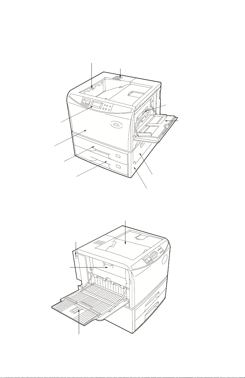
Front and rear views
Front view
Front control panel
Front cover
Upper paper cassette
Lower paper cassette
Left side view
Paper-full sensor
Vent
Option feeder
connector
MP (multipurpose) tray
Paper feeder side cover
Paper feeder
Face-down tray
Left side cover
FS-7000+/FS-9000
Power switch
Face-up paper tray
1-6
Page 22
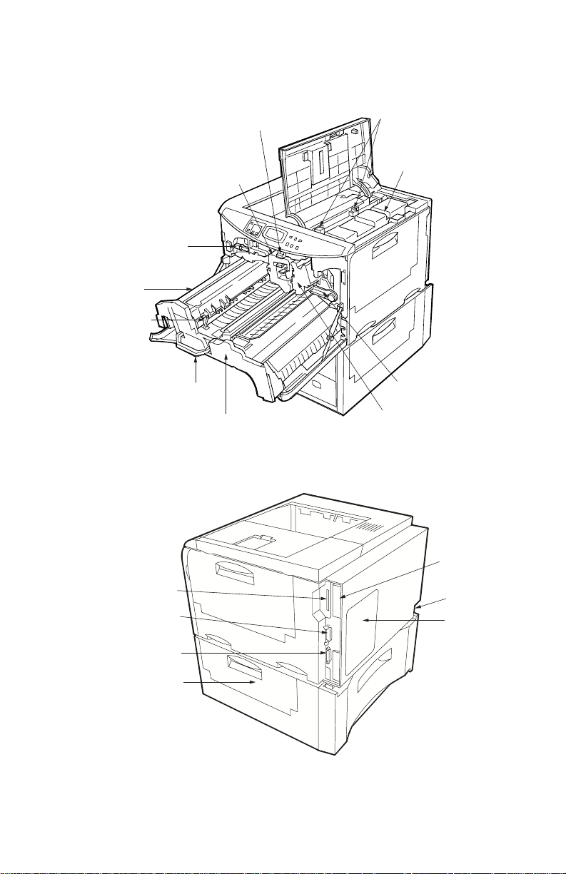
Internal assemblies
Drum release lever
(Green colored)
Toner container release lever
(Green colored)
Fuser unit
Fuser release
lever
Rear view
Memory card slot
Parallel interface
connector
Lock lever
Feed unit handle
(Green colored)
Drum unit
Feed unit
Toner container
Developer release lever
(Gray colored)
Developer
Harddisk
drive slot
Power receptacle
Rear panel
Serial interface
connector
Paper cassette
access door
1-7
FS-7000+/FS-9000
Page 23

Paper handling options
The example option units for the FS-7000+/FS-9000 are shown below. The
User’s Manual
supplied with the printer has more information regarding the accessories available for this
model.
Duplexer
(Inboard)
Paper feeder
supplied as
standard
Bulk paper
stacker,
document
finisher, or
mailbox/ sorter
First optional
paper feeder
Second optional
paper feeder
Wheels (Caster kit)
Options FS-7000+ FS-9000
Duplexer DU-30/ DU-31 DU-31
Paper feeder PF-30 PF-30
Bulk paper stacker ST-30 ST-30
Document finisher DF-30/ DF-31 DF-31
Mailbox/ sorter SO-30 SO-30
Envelope feeder EF-1 EF-1
Universal feeder UF-1 —
Wheels (Caster kit) CA-30 CA-30
FS-7000+/FS-9000
1-8
Page 24
Safety information
Laser notice for service person (U.S.A.)
This printer is certified in the U.S. to conform to the requirements of DHHS 21 Cfr
Subchapter for Class I (1) laser products, and elsewhere is certified as a Class I laser
product conforming to the requirements of IEC 825.
Class I laser products are not considered to be hazardous. The printer contains internally
a Class IIIa (3a) laser that is nominally a 5 milliwatt laser operating in the wavelength region
of 680 nano-meters. The laser system and printer are designed so there is never any human
access to laser radiation above a Class I level during normal operation, user maintenance,
or prescribed service condition.
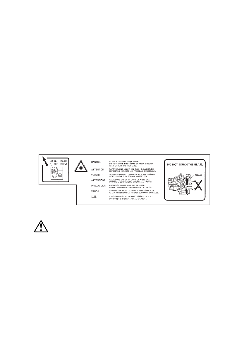
Laser caution label on the scanner unit
The laser scanner unit has the following label affixed atop. Observe these cautionary
statements and figures when handling the laser scanner unit.
Warning
—Use of controls or adjustments or performance of procedures other
than those specified herein may result in hazardous radiation exposure.
1-9
FS-7000+/FS-9000
Page 25

CDRH regulations (U.S.A.)
The Center of Devices and Radiological Health (CDRH) of the U.S. Food and Drug
Administration implemented regulations for laser products on August 2, 1976. These
regulations apply to laser products manufactured after August 1, 1976. Compliance is
mandatory for products marketed in the United States. A label indicating compliance with
the CDRH regulations must be attached to laser products marketed in the United States.
Ozone concentration
Laser printers generate ozone gas (O3) which may concentrate in the place of installation
and cause an unpleasant smell. To minimize the concentration of ozone gas, we recommend
that the laser printer not be installed in a confined area lacking ventilation.
FCC notice (U.S.A.)
This device complies with Part 15 of the FCC Rules. Operation is subject to the following
two conditions: (1) This device may not cause harmful interference, and (2) this device must
accept any interference received, including interference that may cause undesired operation.
This equipment has been tested and found to comply with the limits for a Class B digital
device, pursuant to Part 15 of the FCC Rules. These limits are designed to provide
reasonable protection against harmful interference in a residential installation. This equipment
generates, uses, and can radiate radio frequency energy and, if not installed and used in
accordance with the instructions, may cause harmful interference to radio communication.
However, there is no guarantee that interference will not occur in a particular installation.
If this equipment does cause harmful interference to radio or television reception, which can
be determined by turning the equipment off and on, the user is encouraged to try to correct
the interference by one or more of the following measures:
• Reorient or relocate the receiving antenna.
• Increase the separation between the equipment and receiver.
• Connect the equipment into an outlet on a circuit different from that to which the receiver
is connected.
• Consult the dealer or an experienced radio/TV technician for help.
Change or modifications not expressly approved by the manufacturer for compliance could
void the user’s authority to operate the equipment.
Interference cable to the computer shall be used with shielded circular cable.
Any modification without prior permission may cause harmful interface. If any modification/
change is introduced to this equipment without prior permission, Kyocera, as the manufacturer,
cannot guarantee compliance with FCC rules.
To use equipment which does not comply with FCC rules is prohibited.
FS-7000+/FS-9000
1-10
Page 26

Option equipment
The printer may be optionally installed with the following units, with compliance with class
B limits:
• EF-1—Envelope feeder
• DU-30*/ DU-31—Duplexer
• DO-30—Document stacker
• HD-2—Hard disk unit
• PF-30—Paper feeder (500 sheets)
• ST-30—Bulk paper stacker (3000 sheets)
• UF-1*—Universal feeder
• DF-30*/ DF-31—Document finisher (1800 sheets)
• SO-30—Mail box/Sorter
Important note on the interface connectors
Be sure to turn off printer power before connecting or disconnecting an interface cable to
the printer. For protection against static discharge which may be applied to the printer’s
internal electronics through the interface connector(s), keep any interface connector which
is not in use capped using the protective cap supplied.
Warning—
Class B computing device, pursuant to Subpart J of Part 15 of FCC Rules. Only
peripherals (computer input/output devices, terminals, etc.) certified to comply
with the Class B limits may be attached to this equipment. Operation with non-certified
peripherals is likely to result in interference to radio and TV reception.
This equipment has been certified to comply with the limits for a
*: Optional for FS-7000+ model only.
1-11
FS-7000+/FS-9000
Page 27

Canadian Department of Communications compliance statement
This Class B digital apparatus meets all requirements of the Canadian InterferenceCausing Equipment Regulations.
Avis de conformité aux normes du ministère des Communications du Canada
Cet appareil numérique de la classe B respecte toutes les exigences du Règlement sur le
matériel brouilleur du Canada.
ISO 7779
Maschinenlärminformationsverordnung 3. GSGV, 18.01.1991: Der höchste Schalldruckpegel
beträgt 70 dB(A) oder weniger gemäß ISO 7779.
FS-7000+/FS-9000
1-12
Page 28

Environmental requirements
Environmental conditions
The
Environmental requirements
ensure the optimum operation of the printer. The use of the printer in a location which does
not satisfy the requirements may result in troubles and risk shortening its service life.
The printer will work best if it is installed in a location that is:
• Level and well supported (Place the printer on a sturdy table or desk.)
• Not exposed to sunlight or other bright light (not next to an uncurtained window). Do not
place the printer on an unstable cart, stand, or table.
• Near an AC wall outlet, preferably one that can be used for the printer alone. The outlet
should have a ground slot, or an adapter should be used. If you use an extension cord,
the total length of the power cord plus extension cord should be 17 feet or 5 meters or less.
• Well ventilated, not too hot or cold, and not too damp or dry (See section Environmental
requirements on page Chapter 1-4). If you install the printer where the temperature or
humidity is outside the requirements in section Environmental requirements in chapter 1,
the best print quality may not be expected and there will be an increased chance of paper
jams.
• Provide a sufficient clearances around the printer to ensure ventilation and ease of
access.
section on page Chapter 1-4 should be observed to
1-13
FS-7000+/FS-9000
Page 29

Clearance
Allow the necessary minimum clearance on all sides of the printer (below). A total space of
92 by 138 cm (36 7/8 by 54 5/16") is needed.
5
4
1
3
2
Clearance Dimensions
1 Left 45 cm (17 11/16"), or 30 cm (11 13/16") if the face-up tray is not used.
2 Front 60 cm (23 5/8")
3 Right 45 cm (17 11/16")
4 Back 20 cm (7 7/8")
5 Above 30 cm (11 13/16")
FS-7000+/FS-9000
1-14
Page 30

Places to avoid
Avoid installing the printer in locations exposed to:
• Direct drafts of hot or cold air.
• Direct drafts of outside air. (Avoid locations next to outside doors.)
• Sudden temperature or humidity changes.
• Any source of high heat, such as a radiator or stove.
• Excessive dust. Dust and smoke may cause contamination on the laser scanner window,
causing print quality problem.
• Vibration.
• Ammonia fumes or other harmful fumes. (In case of humigating the room or saturate it with
insecticide, remove the printer first.)
• Avoid greenhouse-like rooms. (Because of sunlight and humidity.)
• Avoid enclosed spaces that block ventilation.
• Avoid sites more than 6500 feet or 2000 meters above sea level.
Note on power
Use only the power source voltage conforming to the printer’s rated power voltage. Do not
use other power sources.
• Disconnect the printer from the power source before attempting removal or re-placement
of an electrical component or a printed-circuit board.
• The printer should not be connected to a power source until the instruction is given to do
so when performing tests described in this manual.
• In connecting the printer power, exercise an extreme care in handling the power supply
or any other electric parts which may give an electric shock.
• Before performing maintenance or repair, power from both the power source and the
associated peripheral devices (computer, sorter, etc.) should be disconnected, unless
otherwise specified.
• To avoid possible electrical shock, extreme caution must be exercised in handling the
power cord and any other electrical part.
• An easily accessible socket outlet must be provided near the equipment.
1-15
FS-7000+/FS-9000
Page 31

About the toner
The printer should use a Kyocera TK-30 or TK-30H toner kit. To ensure the high print quality
and long service life, the following handling precautions should apply.
Caution: As the Ecosys printers are designed to ensure the optimum print quality when
Toner container handling
To loosen and mix the toner inside before use, with the label side down, thoroughly shake
the toner container (in the direction of the arrow) 5 times or more.
used with Kyocera’s proprietary toner, Kyocera do not recommend to use any
refilled toner containers that may be available commercially. This is because
Kyocera have no means of control over how such refilled toner could affect the
print quality and the reliability of the printer.
Caution: Do not attempt to disassemble or refill the toner container.
FS-7000+/FS-9000
1-16
Page 32

Toner storage
The toner contained in the container is susceptible to temperature and humidity. To ensure
the high print quality, store the toner container in a place that satisfies the following
environmental conditions:
Temperature: –20 to 40°C (–4 to 104°F)
Humidity: 15 to 90% RH
Note: If the toner container is removed from the printer’s developer unit, put it in a
protective bag and keep it in a dark place.
Caution: If the printer is shipped for return, etc., do not ship it with the toner container
installed. Otherwise, toner may leak and contamination may result in the printer.
1-17
FS-7000+/FS-9000
Page 33

Chapter 2
INSTALLATION/
OPERATION
Page 34

CONTENTS
Chapter 2 INSTALLATION/OPERATION
Unpacking .................................................................................................................. 2-1
Unpacking the paper feeder ........................................................................................ 2-1
Unpacking the printer .................................................................................................. 2-2
Installing the printer .................................................................................................. 2-3
Connecting the printer and the paper feeder .............................................................. 2-3
Installing toner ............................................................................................................. 2-4
Developer initialization ................................................................................................ 2-7
Expanding memory ................................................................................................... 2-8
Minimum memory requirements .................................................................................. 2-8
SIMM specifications .................................................................................................... 2-8
Notes on handling SIMM ............................................................................................. 2-9
Getting access to the memory sockets ..................................................................... 2-10
Installing SIMM .......................................................................................................... 2-12
Testing the expansion memory ................................................................................. 2-12
Using the Control Panel ......................................................................................... 2-13
Front control panel .................................................................................................... 2-13
Control panel view .................................................................................................... 2-13
Basic key operation ................................................................................................... 2-13
Indicators .................................................................................................................. 2-14
Mode selection menu ................................................................................................ 2-14
Service mode ............................................................................................................ 2-14
FS-7000+/FS-9000
1-1-5
Page 35

Unpacking
The FS-7000+/FS-9000 printer is delivered in two cartons—the printer carton and the paper
feeder carton. Since the paper feeder is installed under the printer, begin unpacking and
installing with the paper feeder.
Unpacking the paper feeder
To unpack the paper feeder, proceed as diagrammed below.
Warning: The paper feeder weighs approximately 20 kg (44 lb.).
Place the paper feeder on a stable, level surface (table, floor, etc.). Note that wheels are
available for the printer as the Caster kit CA-30.
2-1
FS-7000+/FS-9000
Page 36

Unpacking the printer
To unpack the printer, proceed as shown in the diagrams below. Check that the listed parts
are all present.
Warning: The printer weighs approximately 40 kg (88 lb.). Lift it using two or more people.
Do not cut tapes
as they are
reusable for
future packing.
Take out the
accessories:
1 Power cable,
2 Drum unit
cover,
3 Toner kit
4 Documents
incl. CD-ROM.
1
2
3
4
FS-7000+/FS-9000
2-2
Page 37

Installing the printer
Installing the printer requires several steps. Proceed as follows in sequence.
If the printer is used with Caster kit CA-30, fit them now before proceeding.To fit the casters
to the printer, refer to the instructions included in the caster kit.
Connecting the printer and the paper feeder
The printer should be mounted over the paper feeder as shown below. Align the pins 1 and
the connector 2 on the paper feeder with the matching holes and the connector located at
the bottom of the printer, then slowly lower the printer onto the paper feeder.
12
2-3
FS-7000+/FS-9000
Page 38

Installing toner
First open the top cover 1 atop the printer. Slide the toner container release levers 2 to
the right side position. (This is the “open” position in which the toner container becomes
removable.)
2
1
FS-7000+/FS-9000
2-4
Page 39

Take the toner container from the toner kit TK-30 or TK-30H supplied with the printer. With
its label side facing down, give it a good shake (5 to 6 times).
Label side
Peel off the seal 1 on the bottom of the toner container by carefully pulling off.
2-5
1
FS-7000+/FS-9000
Page 40

Insert the toner container in the printer as below. Align the two locating keys at the sides of
the container with the mating slots in the printer.
Locating keys
Caution: To avoid trouble, the toner container must be correctly seated and locked in the
printer. To do this, press the far side of the container 1 at the PUSH HERE
marks.
Making sure that the toner container is seated correctly on the developer, press the two
PUSH HERE markings on the toner container using both hands.
FS-7000+/FS-9000
2-6
Page 41

When the toner container is inserted in the printer properly, slide the toner container release
levers to the left side position until it stops. After installing the toner container, close the top
cover down firmly.
Developer initialization
The printer is shipped from the factory with no toner supplied in its developer unit. When the
printer is first switched on after the toner container is installed in the manner above, there
will be a delay of several minutes before the printer gets ready to print a job.
This delay is necessary for the printer to fill the developer reservoir with a sufficient amount
of toner to continuously support a print job. The period of time for this delay varies depending
on model: approximately 5 minutes.
Since the automatic implementation of the developer initialization is done only once at first
switching power on, if a new developer is installed in the printer, the developer must be
initialized manually using the service mode on the front panel. Refer to the section
toner into the new developer
in chapter 3-11.
2-7
FS-7000+/FS-9000
Feeding
Page 42

Expanding memory
Expanded printer memory is required particularly when a memory error occurs. It enables
the printer to print more complex pages, download more fonts, and define more macros.
Since expanding memory requires removal of the main circuit board from the printer and
handling of SIMM (single in-line memory module), the following procedures should be
followed only by a qualified service technician.
Minimum memory requirements
By default, the printer is equipped with 8 MB*1 or 16 MB*2 of memory at the shipment which
is expandable up to a maximum of 72 MB*1 or 64 MB*2. The minimum memory requirements
for the printer with various options installed are listed in the table below. Refer to this table
for obtaining a rough approximation on how much memory is required for a particular need.
Resolution
Printing environment 300 dpi 600 dpi
HP emulation 2 MB 2 MB
HP+duplex (using duplexer) 2 MB 3 MB
HP+KPDL 2 MB 3 MB
HP+KPDL+duplex 3 MB 5 MB
HP+KPDL+resource protection n/a 10 MB
HP+KPDL+resource protection+duplex n/a 14 MB
Paper size: A4 or Letter
SIMM specifications
Memory size in MB ……………… 4, 8, 16, 32
Number of pins …………………… 72
Access speed …………………… 80 ns or faster
Memory type ……………………… Fast page or EDO non-parity type memory
Bus width ………………………… 32 bits
*1: FS-7000+ model
*2: FS-9000 model
FS-7000+/FS-9000
2-8
Page 43

Notes on handling SIMM
Before proceeding to install SIMM, read the following notes for handling the main circuit
board and SIMMs.
• Protect the electronics by taking these precautions:
• Before touching the main circuit board, touch a water pipe or other large metal object to
discharge yourself of static electricity. While doing the work, it is recommended that you
wear an antistatic wrist strap.
• Touch the main circuit board and SIMM only by the edges, not in the middle. See below.
Yes
No
• Follow the instructions the SIMM manufacturer should provide.
2-9
FS-7000+/FS-9000
Page 44

Getting access to the memory sockets
The main circuit board of the printer is equipped with two sockets for memory expansion.
Expansion memory is available in the form of a SIMM. To gain access to the main board,
the printer’s rear panel should be removed.
Warning: Turn the printer’s power off. Unplug the printer’s power cable and disconnect the
printer from the computer or the network.
Turn the power switch off. Remove the main board access panel 1 by removing 6 (plated)
screws 2. The main controller board 3 is exposed for inserting SIMMs 4.
2
4
3
1
Caution: When the main board is open, use care to avoid foreign objets from entering the
FS-7000+/FS-9000
main board area. Otherwise, a serious damage to the printer could result.
2-10
Page 45

Locate the sockets for the SIMMs on the main controller board by referring to the diagram
on the next page. Locate the sockets for memory expansion on the main board. These
sockets have 72 pins and are symbolized as YS02 and YS03.
FS-9000 comes with 16 MB of SIMM inserted into socket YS03.
API ROM socket
Expansion SIMM sockets
2-11
FS-7000+/FS-9000
Page 46

Installing SIMM
Insert the SIMM 1 into the socket 2 as shown. Carefully push the board upright until it
snaps into place. Make sure that the catches at the ends of the socket fit into the holes 3
at the ends of the SIMM board.
3
1
2
Testing the expansion memory
After installing SIMMs in the printer, test the printer to see if the installation has been
successful. To test the expansion memory, turn printer power on and print a status page.
If the installation has been successful, the
page will show the expanded memory size corresponding to the amount of memory added.
FS-7000+/FS-9000
Total memory
2-12
(Memory Allocation) of the status
Page 47

Using the control panel
This section provides explanation on how to use the printer’s control panel. This is more fully
detailed in the
Front control panel
The printer’s control panel has the LED indicators and a quartz message display to provide
a quick access to the printer’s conditions. It also features the control keys for adjusting the
various conditions on the fly. Note that the adjustments made using these keys may be
overridden by the settings made from within an application software.
Control panel view
L
N
O
N
A
C
Basic key operation
The control keys are used to configure the printer as follows. For more detailed explanations
on these keys, refer to the printer’s
E
IN
L
E
C
user’s manual
IO
T
N
E
T
T
A
A
T
A
D
D
E
E
F
K
C
A
T
S
.
N
IN
T
E
R
F
A
C
E
R
E
S
O
L
U
T
IO
N
S
IZ
E
C
O
P
IE
S
user’s manual
.
E
U
IN
T
N
O
C
IT
X
E
E
D
O
M
D
E
E
F
M
R
O
F
R
E
T
N
E
S
U
T
A
T
S
Key Function
ON LINE Switches the printer online and offline.
CANCEL Abandons a printing job, resets numeric values or cancels a
setting procedure.
STACK Selects whether printed pages are delivered to the face-down or
face-up tray.
FEED Selects the cassette feed or manual (MP tray) feed.
CONTINUE Resumes printing when the message display indicates a memory
error. Also, enters in a submenu item during mode selection.
✚ Cycles forward through the item selections or enters numeric
values.
FORM FEED Prints and feeds out one page. Also, exits a submenu item during
mode selection.
MODE/EXIT Enters/exits the mode selection for changing the printer’s
configuration.
2-13
FS-7000+/FS-9000
Page 48

Key Function
– Cycles reverse through the item selections or enters numeric
ENTER/STATUS Prints a page of status information. During mode selection, this
Indicators
Indicator Status Function
ONLINE/Green Steady The printer is on-line and ready to prints received
DATA/Green Flashing The printer is receiving data from the host computer.
ATTENTION/Red Flashing (1) The printer is warming up. (2) The printer was
Mode selection menu
The MODE key on the control panel allows to set or change the printer environment such
as the number of copies to make, emulation, etc., and to print a font list, manipulating a
memory card, etc.
During operating in the mode selection, several front panel keys serve exclusively for its
secondary function as labeled beside them (EXIT, +, –, ENTER, ▲, ▲). The diagram on
the next page gives a full load map to the full options and the sequence of mode selection
as well as usage of these secondary keys.
values.
key finalizes numeric values and other selections for changing
the printer’s configuration.
data.
Off The printer is off-line. The printer stores but not prints
received data.
Steady The printer is processing the data for printing or for
writing on a memory card.
stopped because of an error such as the insufficient
memory, memory card errors, etc. (See chapter 6.)
Steady (1) The printer needs attention for a problem that can
be cleared by the user such as an open cover,
missing toner kit, paper-full stack, etc. (2) The printer
was stopped because of a problem that needs
servicing provided by a service technician.
Service mode
Within Others option, the Service mode can be accessed by authorized service personnel.
This mode provides the following three treatments for service purpose:
• printing a service information (a service status page)
• cleaning on the drum surface
• accelerating initial toner replenishment for a new developer
The service mode is available only when the printer is ready. To activate these features, see
chapter 3. While in service mode, the printer accepts print data but does not print it.
FS-7000+/FS-9000
2-14
Page 49

Chapter 3
MAINTENANCE/
ADJUSTMENTS
Page 50

CONTENTS
Chapter 3 MAINTENANCE/ADJUSTMENTS
Life expectancy of modules ..................................................................................... 3-1
Toner container .......................................................................................................... 3-2
When to replace the toner container ........................................................................... 3-2
Toner container replacement ....................................................................................... 3-3
Toner saver mode (
Cleaning the printer ................................................................................................... 3-4
Main charger unit ......................................................................................................... 3-4
Cleaning the paper feed unit ........................................................................................ 3-7
Replacing the developer unit .................................................................................... 3-9
Replacement ................................................................................................................ 3-9
Installing a new developer ......................................................................................... 3-10
Feeding toner into the new developer........................................................................ 3-11
Updating the firmware ............................................................................................. 3-12
Firmware data format ................................................................................................. 3-12
Downloading engine firmware data............................................................................ 3-13
Downloading controller firmware data........................................................................ 3-13
Downloading data from a memory card ..................................................................... 3-14
Errors during downloading ......................................................................................... 3-15
Adjusting the paper type ......................................................................................... 3-16
Fuser temperature ..................................................................................................... 3-16
Transfer bias potential ............................................................................................... 3-16
EcoPrint
) ....................................................................................... 3-3
FS-7000+/FS-9000
1-1-7
Page 51

Life expectancy of modules
The table below shows the nominal life expectancy for modules. Detailed part information
for each module (except toner containers) can be found in
For refurbishment purpose, the modules are available as a kit after 350,000 pages have
been printed. The contents of this kit is also shown in this table.
Module kit Nominal life
FS-7000+ FS-9000 Module (pages) Remarks
TK-30 Toner container 25,000 User-replaceable (20,000
TK-30H 33,000 pages for the initially supplied
DK-33 DK-35 Drum unit 350,000
DV-35 DV-35 Developer unit 350,000
FK-30 FK-35 Fuser unit 350,000
TR-35 TR-35 Transfer roller 350,000
MK-33 MK-35 Refurbishment 350,000 Includes a drum unit, developer
(“Maintenance”) kit*
SK-33 SK-35 Service kit 1,050,000
*1 To install the kit, refer to the instruction manual included in the kit.
*2 Not included in SK-33.
1
Parts Catalog
container)
unit, fuser unit, transfer roller,
waste toner conveyer, a pair of
MP tray rollers (ROLLER
RETARD ASSY, 2), and two
pairs of PF-30 rollers (ROLLER
FEED ASSY, 4)
Includes DRIVE UNIT (1),
SEPARATOR ASSY (1),
CLUTCH ASSY FOR PF-30
(4), TORQUE LIMITTER FOR
PF-30 (2), ROLLER NIP FEED
FOR PF-30 (2), LATCH JOINT
(1), ROLLER REGIST LOW (1),
SEET REGIST (1),
ACUTATOR REGIST*2 (1), and
ROLLER MIDDLE*2 (1).
.
3-1
FS-7000+/FS-9000
Page 52

Toner container
The toner container is the only consumable that the printer requests (until it has printed
350,000 pages) to replace periodically during normal operation (user-replaceable). The
following toner container is available for use both printer models.
Model
Toner kit TK-30 TK-30H
Life in pages* 25,000 33,000
* Based on letter or A4 size paper; average
print density of 5%.
When to replace the toner container
The printer gives two steps of user attention for toner replacement as explained below:
Step 1—The toner is almost run out. The message display indicates:
Replace Toner … Clean printer
The printer will print approximately 25,000/33,000 pages (A4 or letter/5% coverage) until
step 2. This is the earliest chance to replace the toner container and clean various parts
inside the printer (See Cleaning the printer on page Chapter 3-4).
Step 2—The toner is run out. The printer halts printing and the message display indicates:
Replace Toner … Clean printer
This instructs the user to install a new toner kit to bring the printer back in normal operation.
Cleaning various parts inside must be also done in this occasion (See Cleaning the printer
on page Chapter 3-4).
Observe the following cautions when replacing the toner container:
• Do not attempt to disassemble the toner container and reuse the waste toner inside.
• Keep magnetic media such as floppy disks away from the toner container.
• Be sure to clean the parts as instructed in this section at the same timing of replacing toner
container.
• Use of the Kyocera toner kit TK-30 or TK-30H is highly recommended for the optimum
operation of the printer.
FS-7000+/FS-9000
3-2
Page 53

Toner container replacement
To replace the toner container, open the top cover 1. Pull the toner container release levers
2 to the right position as shown. Lift and pull out the toner container 3.
2
1
3
Then, refer to section Installing toner in chapter 2 to install the new toner container. After
installing the new toner container, several parts in the printer must be cleaned as instructed
in section Cleaning the printer on page Chapter 3-4.
If the toner container has been replaced when the message
Replace Toner … Clean printer
was displayed, then, the message
Clean printer … press CONTINUE
will be displayed after replacement. After cleaning the inside of the printer following the
procedure shown below, press the CONTINUE key; the message will disappear and the
printer will be ready for printing.
Toner saver mode (
The
EcoPrint
printing costs by drastically extending the toner container life. EcoPrint mode is factory-set
to off and turned on by the printer’s front control panel (also accessible through the
application software with the assistance of the printer driver). See details in the printer’s
User’s Manual.
EcoPrint
enables to reduce the amount of toner consumed on the page so as to save
)
3-3
FS-7000+/FS-9000
Page 54

Cleaning the printer
To avoid print quality problems, the following printer parts must be cleaned with every toner
container replacement.
Main charger unit
The main charger unit should be cleaned in its two parts—the charger wire and grid (See
the picture below.)—whenever the toner container is changed. Cleaning of the main charger
can be done without needing any tools thanks to its self-cleaning system.
Back
Grid
Charger wire
Front
FS-7000+/FS-9000
3-4
Page 55

To clean the charger wire, first open the front cover 1. Pull the cleaning knob (green) 2
slowly in and out a few times. This pulls a cleaning pad inside the drum unit along the wire.
2
1
Then, clean the grid using the grid cleaner supplied with the toner kit.
Take the grid cleaner 3 from protective bag in the new toner kit, and remove the cap 4.
4
Pad (impregnated with water)
3
The grid cleaner pad is impregnated with water. Perform the following cleaning procedure
before the pad dries.
3-5
FS-7000+/FS-9000
Page 56

Attach the grid cleaner 3 to the drum unit as shown in the diagram below. Insert the fixture
pin on the cleaner into the hole on the drum unit with the pad facing up.
3
Hold and pull up the main charger, then draw it out until it stops. Then, push it all the way
in. Repeat this procedure for 5 times or more.
To release the
main charger
unit for pulling,
first pull it up…
Then, pull it
horizontally
out.
After cleaning is done, pull the main charger unit in place using the reverse manner of the
above. Close the front cover.
FS-7000+/FS-9000
3-6
Page 57

Cleaning the paper feed unit
The paper feed unit must be cleaned of paper dust whenever the toner container is
replaced. To gain access to the paper feed unit, first, open the front cover. Turn the lock
lever counterclockwise. Draw out the paper feed unit by the handle (green) 5 on its front
side.
Cleaning the paper feed unit should be done on several parts—the separation charger,
registration rollers, paper ramp, etc. as follows.
Caution: Do not touch the transfer roller (black sponge roller) 6 during the cleaning
procedure.
Take out the cleaning brush 7 recessed in the front of the paper feed unit. Cleaning the
separation charger (saw-toothed) 8 by sweeping with the brush 9.
8
Lock lever
7
9
3-7
5
6
FS-7000+/FS-9000
Page 58

Obtain the cleaning cloth (Locate in a new toner kit or contact Kyocera). Wipe the
registration rollers 0 and paper ramp ! as shown below.
0
!
When cleaning is done, set the paper feed unit back in place by pushing on the handle. Make
sure that the paper feed unit has been correctly seated, turn the lock lever clockwise, close
the front cover.
The printer can get ready for printing approximately 15 seconds after replacing the toner
container.
FS-7000+/FS-9000
3-8
Page 59

Replacing the developer unit
In case that the developer unit is to be removed from the printer for shipment or replacing
to a new one, it should be handled following the instructions below.
Also, a new developer unit, after installing, needs a special treatment that replenishes the
developer with toner for printing. This can be done by using the front control panel (See
section Feeding toner into the new developer on page Chapter 3-11).
Replacement
To replace the developer unit currently installed in the printer, first turn the printer power off.
Open the toner container access door. Refer to section Toner container replacement on
page Chapter 3-3 and remove the toner container. Open the front cover. Locate the
developer unit release lever 1 and turn it clockwise to the upper position. Grasp the
developer’s front end as shown below and slowly draw the developer 2 out from the printer.
1
2
Caution: If you ship the developer unit removed from the printer for repair, etc., pack the
developer in the container package designed for this purpose.
3-9
FS-7000+/FS-9000
Page 60

Installing a new developer
To install a new developer, use the reverse manner as above. Note that the new developer
is shipped from the factory with a protective cover 1 installed. Leave the protective cover
installed with the developer until the developer has been installed in the printer.
When the developer has been installed in the printer, grasp and pull the protective cover all
the way out, as shown below. Latch in the developer release lever.
1
Caution: Push in the developer unit slow and gently. If the developer contains toner,
pushing in the developer unit rudely can cause the distribution of toner to become
uneven in the far side of the developer. Also, it may risk damaging the connector
at the far end of the developer (and the mating connector in the printer).
FS-7000+/FS-9000
3-10
Page 61

Feeding toner into the new developer
The new developer unit is shipped from the factory with no toner contained. The developer
can be automatically replenished with toner when a toner container is installed onto it and
the printer is turned on. However, because the toner reservoir in the developer has a large
capacity, it requires a lengthy period of time until a substantial amount of toner has been fed
to get the printer ready.
A great many seconds of time for this is greatly deducted by using the service menu in the
printer’s mode select routine as accessed by its front control panel. Follow these steps to
use this feature, top to bottom. (For details on using the front control panel keys, refer to the
printer’s user’s manual.)
Key to press: Relevant display:
MODE
✚ (repeatedly)
Others>
▲
✚ (repeatedly)
▲
ENTER
ENTER Turn printer power off, then on.
When printer power is turned on again, the printer continually engages in this mode for
several minutes after which the printer reverts to the ready state.
>Service>
>>Developer
>>Developer?
3-11
FS-7000+/FS-9000
Page 62

Updating the firmware
The printer accepts update of the engine and system firmware as well as the front panel
message data through the parallel interface. A PC that is connected to the printer’s parallel
interface and capable of running in DOS mode is required for this purpose.
Updating using these data is implemented by directly downloading the new firmware data
for rewriting the flush memory chips in the printer. The printer must enter to the
mode (See page Chapter 3-13) to update the engine firmware using Prescribe commands
as explained in this section.
The engine firmware and controller (system) firmware must be updated separately.
Kyocera supply three types of data for updating the printer’s firmware as follows:
• Engine firmware data
• Controller (system) firmware data
• Front panel message data
These data may be stored in a memory card for field use. To store (write) data in a memory
card, and reread them into the printer through the slot, refer to the printer’s
Each single data must be written on a memory card. Do not write more than one data on
a memory card.
Firmware data format
The firmware data to be downloaded is identified using the following file specification:
supervisor
User’s Manual
.
1
2
3
4
FS-7000+/FS-9000
de3630.dat
1 23 4
Identifies…
de: Engine firmware data
ds: Controller (system) firmware data
dm: Front panel message data
36: FS-7000+
31: FS-9000
Version of data (2 to 4 digits)
dat: Engine or controller firmware data
dan: Panel message data for Danish
swe: Panel message data for Swedish
ita: Panel message data for Italian
spa: Panel message data for Spanish
3-12
Page 63

Downloading engine firmware data
Ready
Downloading
Ready
Ready
Downloading
To download engine firmware or panel message data, use Prescribe BOOT command.
Perform in sequence: Relevant display
Turn printer power on. Make sure the printer is
Ready
.
At the DOS prompt, send the following command to the
printer.
Supervisor mode
!R! BOOT "SPR";
Note: Do not add an EXIT; command in the above.
The display indicates Supervisor mode when the
above command is sent to the printer.
DOS COPY (/b) the data to download from the host
computer. The display shows Downloading while
downloading data.
When downloading finishes, the display reverts to
Supervisor mode. In this state, turn power off.
Turn power on again. Check the display shows Ready.
Caution: Do not turn off printer power while data are being downloaded (approximately
Confirm the status page shows the new engine version. If the message display indicates
Call service person Dn (n=0, 1, …)
Chapter 3-15.
Downloading controller firmware data
To download controller firmware data, use Prescribe UPGR command as follows.
Perform in sequence: Relevant display
Turn printer power on. Make sure the printer is
one minute).
, refer to section
Ready
Supervisor mode
Errors during downloading
.
on page
At the DOS prompt, send the following command to the
printer:
!R! UPGR "SYS";
Note: Do not add an EXIT; command in the above.
The display should indicate Supervisor Mode when the
above command is sent to the printer.
DOS COPY (/b) the data to download from the host
computer. The display shows Downloading while
downloading data.
3-13
Supervisor mode
FS-7000+/FS-9000
Page 64

When downloading finishes, the display reverts to
Ready
Downloading
Ready
Supervisor mode. In this state, turn power off.
Turn power on again. Check the display shows Ready.
If not, refer to section Errors during downloading on page
Chapter 3-15.
Supervisor mode
Caution: Downloading controller firmware takes several minutes (depending on the
Confirm the status page shows the new firmware version (See
message display indicates
downloading
Downloading data from a memory card
To download data written in a memory card to the printer, proceed as follows. Data in a
memory card can be selectively downloaded when the Prescribe RWER command is used.
Refer to the
printer for details about the RWER command.
Perform in sequence: Relevant display
Insert the memory card in the printer’s memory card slot
of the printer.
Turn printer power on. The printer automatically reads
data in the memory card, indicating Downloading on
the message panel during downloading.
When the data is successfully read, the message display
indicates Supervisor mode.
Turn printer power off.
Remove the memory card from the printer.
Turn printer power on again. Check the display shows
Ready.
processing speed of the computer used). Do not turn power off during downloading.
on page Chapter 3-15.
Call service person Dn (n=0, 1, …)
Prescribe Command Reference Manual
Appendix B
, refer to section
in the CD-ROM purchased with the
, page B-4). If the
Errors during
Supervisor mode
Confirm the status page shows the new firmware version (See
message display indicates
downloading
FS-7000+/FS-9000
below.
Call service person Dn (n=0, 1, …)
3-14
Appendix B
, refer to section
, page B-2). If the
Errors during
Page 65

Errors during downloading
The following messages may be indicated on the message display when an error occurred
during downloading firmware data. Take the appropriate corrective action. If the corrective
action does not terminate the error, contact the Kyocera.
Error message Meaning Corrective action
Call service person
D0 - Checksum error
Call service person
D1 - Machine compatibility
error
Call service person
D2 - Version compatibility
error
Call service person
D3 - Data error
Checksum error occurred
during downloading. The
engine ROM is empty.
The data to be downloaded is
not compatible with the
printer.
The version of the data does
not match the current engine
version.
The data to be downloaded is
corrupted.
Turn printer power off
once, then on again.
Try downloading again.
Obtain correct data for
the printer model.
Obtain the correct
version of data.
Obtain the correct data.
3-15
FS-7000+/FS-9000
Page 66

Adjusting the paper type
The models FS-7000+ and FS-9000 is capable of printing optimally on the wide varying
range of paper types. By selecting the appropriate paper type from the printer’s control
panel, the printer automatically selects the predetermined combination of a fuser temperature
and a transfer bias potential that is optimized for the specific type of paper.
It is also possible to create a customized combination of the fuser temperature and the
transfer bias potential depending on the enduser need.
Details for selecting and customizing those settings are given in chapter 2 of the printer’s
user’s manual.
The following section is intended to give a brief overview on how the fuser temperature and
the transfer potential are preadjusted at the factory.
Fuser temperature
Fuser mode Fuser temerature
Hi Approx. 200°C/ 392°F
Middle Approx. 200°C/ 392°F
Low Approx. 185°C/ 365°F
Vellum Approx. 185°C/ 365°F
Transfer bias potential
Paper type Transfer bias
Thin -1.7kV*1 or -2.1kV*
Normal -1.7kV*1 or -2.1kV*
Thick -2.2kV*1 or -2.4kV*
*1: FS-7000+ model
*2: FS-9000 model
2
2
2
FS-7000+/FS-9000
3-16
Page 67

Chapter 4
OPERATION
OVERVIEW
Page 68

CONTENTS
Chapter 4 OPERATION OVERVIEW
Electrophotographics system .................................................................................. 4-1
Electrophotographic cycle ........................................................................................... 4-1
Amorphous-silicon drum ............................................................................................. 4-2
Charging the drum ...................................................................................................... 4-3
Toner ........................................................................................................................... 4-4
Exposure ..................................................................................................................... 4-5
Scanner unit ................................................................................................................ 4-6
Laser scanning ............................................................................................................ 4-9
Development ............................................................................................................. 4-10
Developing roller bias ................................................................................................ 4-11
Image transfer ........................................................................................................... 4-13
Paper separation........................................................................................................ 4-13
Fusing ....................................................................................................................... 4-14
Drum cleaning and erasing static charge .................................................................. 4-16
Typical photo process timing chart ............................................................................ 4-17
Paper feeding system ............................................................................................. 4-18
Paper control signals ................................................................................................. 4-19
Paper feeding components ....................................................................................... 4-20
Control devices ......................................................................................................... 4-21
Paper feeder PF-30 control devices ......................................................................... 4-22
Printing from paper feeder PF-30 cassettes ............................................................. 4-23
Printing from the MP tray .......................................................................................... 4-24
Printing from the optional envelope feeder ............................................................... 4-25
Paper jam detection .................................................................................................. 4-26
Message display at a paper jam ............................................................................... 4-28
Print timing charts .................................................................................................. 4-29
Signal and symbols .................................................................................................... 4-29
Print timing chart ........................................................................................................ 4-30
Basic engine functions ........................................................................................... 4-36
Engine controller system ....................................................................................... 4-37
Configuration memory ............................................................................................... 4-37
High-voltage generator ............................................................................................. 4-37
Laser scanner control ............................................................................................... 4-37
Polygon motor control ............................................................................................... 4-37
Safety interlock ......................................................................................................... 4-38
The engine gate arrays ............................................................................................. 4-39
The engine CPU ....................................................................................................... 4-43
Power supply ............................................................................................................ 4-44
Power distribution ..................................................................................................... 4-46
FS-7000+/FS-9000
1-1-9
Page 69

Logic controller system ......................................................................................... 4-47
Main logic controller overview ................................................................................... 4-47
Main logic controller block diagram ........................................................................... 4-48
Printing data processing ........................................................................................... 4-49
Main logic component ............................................................................................... 4-50
CPU (U01) ................................................................................................................. 4-50
ASIC (U02)................................................................................................................. 4-50
ASIC (U03)................................................................................................................. 4-50
API ROM socket (U09E) ........................................................................................... 4-50
API ROM socket pin assignment .............................................................................. 4-51
System DIMM (YS01) ............................................................................................... 4-52
RAM (U10 and U13) ................................................................................................. 4-52
Memory card slot interface (YC6) ............................................................................. 4-52
KUIO interface (YC02/YC03) .................................................................................... 4-53
Parallel interface ....................................................................................................... 4-54
Serial interface .......................................................................................................... 4-54
Engine interface ........................................................................................................ 4-55
Engine interface connector assignment .................................................................... 4-55
Signals used for the engine interface ........................................................................ 4-56
Engine interface signals ............................................................................................. 4-57
FS-7000+/FS-9000
1-1-10
Page 70

Electrophotographics system
Electrophotography
is the technology used in laser printing which transfers data representing
texts or graphics objects into a visible image which is developed on the photosensitive drum,
finally fusing on paper, using light beam generated by a laser diode.
The key features for the electrophotography system of the printer are:
• Real 600 dpi resolution (equivalent to 2400 dpi resolution thanks to KIR smoothing
technique)
• Ultra long life amorphous silicon drum (non-heating)
• Paper support for up to A3 (Ledger) size
• Microfine mono component toner
Electrophotographic cycle
The electrophotography system of the printer performs a cyclic action made of seven steps
as follows. Each step is technically explained in the following sections.
2 Exposure
1 Main Charging
7 Erasing
6 Cleaning
3 Developing
4 Transfer
5 Fusing
4-1
FS-7000+/FS-9000
Page 71

Amorphous-silicon drum
The printer uses the long lasting amorphous silicon (a-Si) drum. The photoconductive layer
is coated over the aluminum cylinder base as shown below. The aluminum base is
electrically grounded to the ground.
The photoconductive layer is charged evenly over its surface by positive high voltage
charging (corona charging) given by the main charger unit (the wire and grid). The area on
the charged drum surface which is exposed to the laser beam, as the print image is
statistically drawn over the drum, loses the charge as it is escaped through the ground. The
resultant electrostatic latent (negative) image is then developed by toner and transfer to the
medium like paper.
The amorphous silicon photo conductor is extremely hard, non-toxic, and highly resistive
against chemical substances. These characteristics of the amorphous material make itself
up to a most durable, stable photoconductor for the electrophotography printer.
Photoconductive layer
FS-7000+/FS-9000
Aluminum base cylinder
4-2
Page 72

Charging the drum
Figure below is a simplified diagram of the electrophotographics components. Charging the
drum is done by the main charger unit marked A in the diagram.
A
B
As the drum B rotates in a “clean (neutral)” state, its photoconductive layer is given a
uniform, positive (+) corona charge dispersed by the main charger wire A.
Due to high-voltage scorotron charging, the charging wire can get contaminated by
oxidization and therefore must be cleaned periodically from time to time using the method
explained in chapter 3. Cleaning the charging wire prevents print quality problems such as
black streaks caused by the oxide ac-cumulated around the charging wire.
4-3
FS-7000+/FS-9000
Page 73

Toner
The toner is fed from toner kit TK-30 or TK-30H. The toner is of dry mono component type
and comprised of the following substances as depicted below.
Single component toner TK-30 or TK-30H
A Resin
B Ferrite
C Silica
D Polisher
A
B
C
D
FS-7000+/FS-9000
4-4
Page 74

Exposure
The charged surface of the drum B is then scanned by the laser beam from the scanner
unit A.
A
B
The laser beam is switched on for a black dot and off for a white (blank) dot according to
the print data. Whenever it is illuminated by the laser beam, the electrical resistance of the
photoconductor is reduced, the potential on the photoconductor is also lowered from
approximately 250 V to 20 V, effectively driving the charge through the a-Si layer down to
the aluminum base.
+++++
a-Si LAYER
ALUMINUM
LASER BEAM
++++
– – – –
++++
4-5
0 V
LASER BEAM
250 V
20 V
FS-7000+/FS-9000
Page 75

Scanner unit
The 600 dpi scanner unit includes the laser diode that produces the 670 nm wavelength
laser beam. This wavelength is specifically designed to match the photoconductive
response of amorphous silicon.
The diagrams below show the components inside the scanner unit in two views—horizontal
and vertical. The function of each component is described in the following pages. Note that
the directive arrows indicate the laser beam paths.
TOP VIEW
7
4
0
3
9
2
5
6
1
FS-7000+/FS-9000
4-6
Page 76

SIDE VIEW
8
Drum
1 Laser diode ...................................... emits diffused, visible laser.
2 Collimeter lens ................................. aligns the laser beam to the cylindrical lens.
3 Cylindrical lens ................................. compensates the slant angle at which the laser
4 Polygon mirror (motor) ..................... has ten mirror segments around its octagonal
5 Primary f-theta lens.......................... See below.
6 Secondary f-theta lens..................... The primary (above) and secondary f-theta lenses
beam hits a polygon mirror segment.
circumference; each mirror corresponding to one
scanned line width on the drum when laser beam
scans on it.
equalize focusing distortion on the drum edges.
The effective length of line (“A,” “B” below) the
laser beam draws on the drum becomes longer as
the laser beam hits closer to the drum edges. In
the figure below, distances represented by “A”
and “B” are not the same (A > B) until the f-theta
lenses are provided between the polygon mirror
and the drum (A’ = B).
4-7
FS-7000+/FS-9000
Page 77

Secondary f-theta lens
A
A
B
Primary f-theta lens
θ
θ
Polygon mirror
Laser diode
7 Diversion mirror................................ diverts the laser beam vertically onto the drum.
Note the diffused laser beam finally pin-points on
the drum.
8 Protective glass................................prevents dust, debris, etc., from entering the
scanner assembly.
9 Sensor mirror ................................... bends the very first shot of a laser scan towards
the beam detection sensor (See next.).
0 Beam detector sensor...................... when shone by the sensor mirror above, this
photosensor generates a trigger signal for the
engine controller to start activating the paper
feeding system.
FS-7000+/FS-9000
4-8
Page 78

Laser scanning
The laser beam hits one of ten polygonal mirrors. As the mirror revolves (at the nominal
revolution of 17,700 rpm*1 or 24,000 rpm*2), the laser beam reflects off of it and reaches the
charged drum surface in a lengthwise manner.
A pair of (plastic) lenses provides focusing the horizontally sweeping laser beam onto the
drum. As the drum rotates, the laser beam sweeps the entire length of the drum so that the
drum’s entire circumference is exposed to the laser beam. The revolution of the polygon
mirror motor and the drum itself is timing-controlled so that each successive sweeping of
the laser beam produces a 1/
turns the laser beam on and off to put a dot at every 1/
inch offset. The printer’s controller system continuously
600
inch distance horizontally.
600
Synchronizing the output data with one scanning line is achieved by the photo sensor
provided next to the first mirror. At the beginning of each laser sweeping, the beam hits the
photo sensor which in turn sends a command to the logic controller for synchronization.
*1: FS-7000+ model
*2: FS-9000 model
4-9
FS-7000+/FS-9000
Page 79

Development
The latent image constituted on the drum is
developed
into a visible image. The developing
roller contains a magnet core and an aluminum cylinder rotating around the magnet core
at a speed twice faster than that of the drum. Toner attracts to the developing roller since
it is magnetic. A magnetized blade above the developing roller constitutes a smooth layer
of toner in accordance with the roller revolution.
Blade
Magnetism
Drum
0.1 mm
Magnet
0.3 – 0.4 mm
Developing roller
FS-7000+/FS-9000
4-10
Page 80

Developing roller bias
The developing bias is adjusted so that the toner, charged positive while each particle is
rubbing each other in the developer, is selectively developed onto the area of low potential
by adhering. The bias is AC weighted, positive DC power source.
Since the gap between the developing roller and the drum is wider than the average
diameter of the toner, the toner should
fly
over to the drum surface to accomplish
development. This method is known as the non-contact development method.
Blade
Develop. roller
Drum
AC + DC
Toner
Toner
Toner sensor
Develop. rollerDrum
4-11
FS-7000+/FS-9000
Page 81

Surface
potential =
250 V
Area not exposed by laser
Area exposed by laser
Developing roller bias
160 V DC + 1.8 kV AC
Developing
+++++++
20 V
Toner
A toner replenishment sensor is provided within the developer. As the toner supply from the
toner container dwindles and the toner level lowers in the reservoir, the sensor translates
it through its sensing plate, urging the toner motor to feed more toner.
Sensing plate
Toner sensor
Sensable level
Toner
Developer unit
FS-7000+/FS-9000
4-12
Page 82

Image transfer
The image developed by toner on the drum (A below) is transferred onto the paper using
the electric charge attraction given by the toner itself and the transfer roller (B below). The
transfer roller is negatively biased so that the positively charged toner is attracted onto the
paper while it is pinched by the drum and the transfer roller.
A
+
B
The nominal transfer bias is set to approximately –1.7 kV*1/–2.1 kV*2 (limit) with the 55 µA*1/
80 µA*2 current. Since the ideal potential of the transfer bias varies depending on the
thickness of paper, the bias is raised to approximately –2.2 kV*1/–2.8 kV*2/55 µA*1/80 µA*
for thicker paper (91 to 200 g/m2). Double-sided printing using a DU-30*3/DU-31 duplexer
automatically increases the transfer bias to the above value. On the other hand, the bias
current is reduced to 55 µA*1/60 µA*2 (–1.7 kV*1/–2.1 kV*2) for thin paper. The bias is
switched automatically as the printer detects the thickness of the paper, and also switchable
manually on the printer’s control panel. For details on switching the transfer bias, refer to
the printer’s user’s manual.
Paper separation
After the image transfer process, the paper is forcibly peeled off the drum by means of the
separation electrode. The separation electrode is located next to the transfer roller, giving
the positive charge to attract paper downwards.
–
*1: FS-7000+ model
*2: FS-9000 model
*3: Optional for FS-7000+ model only.
2
4-13
FS-7000+/FS-9000
Page 83

Fusing
The toner on the paper is permanently fused onto the paper as it passes between the florinfinished heat roller (A below) and the pressure roller (B below) in the fuser unit. The toner
is molten and pressed into the paper.
A
B
The heat roller has two halogen lamps, turning alternatively on depending on the size of the
paper passing through to maintain the preheat temperature at approximately 185°C/365°F.
This ensures the even temperature dispersal over the long heat roller. See the picture below
and table in the next page.
Heat distribution
FS-7000+/FS-9000
Thermo-cutThermistor
Engine
Controller
4-14
Page 84

Heater(s) activated
Paper size Middle heater Edge heater
Idle
A3, A4 landscape On+ On
B4 On+ On
Letter landscape On+ On
Letter, A4, A5 On Off
Ledger On+ On
The heat roller temperature is constantly monitored by the engine control circuit using the
a thermistor. In the above table, each heater is turned “On” as commanded by the
thermistor. The “On+” status for paper sizes of B4 and letter (landscape) mean that the
heater is turned on a couple of seconds longer than that commanded by the thermistor.
Off On
4-15
FS-7000+/FS-9000
Page 85

Drum cleaning and erasing static charge
The drum needs to be physically cleaned of toner which is remaining on its surface in the
development process. The cleaning blade (A below) is constantly pressed against the
drum and scrapes the residual toner on the drum off to the refresher roller (B below). The
refresher roller drives the toner to the spiral (fins) roller (C below). The waste toner is
collected at the output end of the spiral roller and sent back to the toner container, into the
waste toner reservoir.
D
A
CB
After the drum is physically cleaned, it then must be cleaned to an electrically neutral state.
This is necessary to erase any residual positive charges, ready to accept the next uniform
charge. The residual charge is canceled by exposing the drum to the light emitted from the
eraser LED (D above). This lowers the electrical conductivity of the drum surface making
the residual charge on the drum surface escape to the ground.
FS-7000+/FS-9000
4-16
Page 86

Typical photo process timing chart
The following chart shows the signals used for photo processing. These signals activate the
corresponding device in the following timing sequences. A simple description for these
signals follow.
Page 1 Page 2
MOTOR
PAPER
MHVDR
ERASER
A
BIAS
B
THVDR
SHVDR
MHVDR (Main High Voltage Drive) — turns on the main charger bias for charging the
toner. This signal is kept on during the job is being processed.
ERASER — turns on the eraser (LED array) as soon as the motor begins to rotate revolving.
BIAS — turns on the developer bias on the magnet roller. The duration of this signal is
dependent on the current paper size. The bias is reduced to approx. 100 V between paper
A. This avoids gray background effect by attracting excessive toner on the magnet roller
onto the drum (which will subsequently be collected back in the drum unit by means of the
cleaning blade).
THVDR (Transfer High Voltage Drive) — turns on the transfer bias. Note that the transfer
bias is weakened (from –1—2 kV to –600 V*1/+400 V*2) while paper is not present between
the transfer roller and the drum unit. This avoids contamination on the back side of paper
B.
SHVDR (Separation-charger High Voltage Drive) — turns on the separator to scrape the
paper off of the drum unit.
*1: FS-7000+ model
*2: FS-9000 model
4-17
FS-7000+/FS-9000
Page 87

Paper feeding system
The paper feeder providing two paper cassettes is fitted to the printer externally at the
bottom of the printer. The printer can be installed with up to 6 cassettes by adding up to two
more paper feeder options (PF-30 basically the same paper feeder fitted as the standard
paper feeder).
The paper feeding system picks up paper from the cassette or the MP tray. At a precise
timing, it feeds it to the electrophotography system. It finally delivers the printed page to
either the face-down or face-up tray, or to the optional stacker/finisher.
The figure below shows the components in the paper path within the printer. The sensors,
solenoids, etc., are also described in the following pages.
PAPER FEEDING DIAGRAM
6
4
5
3
2
2
1
1 Paper cassette(PF-30 Paper feeder)
2 Paper feed rollers
3 Registration rollers+clutch
4 Drum
5 Transfer roller
6 Fuser rollers
7 Manual feed roller
7
FS-7000+/FS-9000
4-18
Page 88

Paper control signals
The following diagram shows the control signals that control the sensors and the rollers for
guiding paper. The engine controller provides these signals in conjunction with the
electrophotography process that is driven by the main controller system.
Engine Controller
Stack
solenoid
PAPFL*
JAMFD*
Face-down
paper-full
sensor
FDWSD*/FUPSD*
Face-down
jam sensor
Face-up
jam sensor
Pressure Roller
PF-30 Paper feeder
Heat Roller
MMOT*
M
Separation
charger
Paper Cassette
Paper Cassette
THVDR*
RHVDR*
Regist.
Drum
clutch
Transfer roller
REGCL*
Regist.
sensor
Regist roller
Paper
sensor
Paper
sensor
JAMR*
jam
SUBCL*
Subclutch
ENVPASS*
Envel.
pass
sensor
MFEED*
Manual
feed
clutch
MPFPAP*
MPF
paper
sensor
Clutches
Sensors
Rollers
EMOT*
M
MP tray
4-19
FS-7000+/FS-9000
Page 89

Paper feeding components
The figure below shows the locations of the sensors, clutches, microswitches, and fans.
Each number corresponds to the description in the table on the next page. The board Ids
accompany those parts mounted on the board.
0
4
5
8
)
fi
·
„
3
6
´
!
2
fl‚
9
1
@
*
^
&
#
$
7
%
(
⁄
¤
‡
Œ
›
‰
‹
—
ˇˆÁ¨Ø
FS-7000+/FS-9000
4-20
Page 90

Control devices
Symbol Title Location Board
1 Controller box fan (FAN3) Controller box
2 Printer side cover switch Face-down unit KP-552
3 Face-down paper-full sensor Face-down unit
4 Face-down jam sensor Face-down unit
5 Face-up jam sensor Face-down unit
6 Face-up/down solenoid Face-down unit
7 Toner container switch Rear frame
8 Interlock switch—front Front frame
9 Drum/fuser fan (FAN1) Rear frame
10 Tower sensor Rear frame KP-574
11 Power supply fan (FAN2) Shield box
12 Main motor Drive unit
13 Registration clutch Drive unit
14 Intermediate clutch Drive unit
15 Registration jam sensor Rear frame
16 Interlock switch–top MP feed unit
17 Top cover switch MP feed unit
18 Toner container sensor MP feed unit KP-603
19 MPF paper sensor MP feed unit
20 MPF paper size sensors 1 and 2 MP feed unit KP-576
21 MPF solenoid MP feed unit
22 Envelope feeder sensor MP feed unit
4-21
FS-7000+/FS-9000
Page 91

Paper feeder PF-30 control devices
Symbol Title Location Board
23 Right side cover switch
24 Upper cassette paper sensor/bottom limit Upper cassette KP-583
sensor
25 Upper cassette paper size sensors 1/2/3 Upper cassette KP-581
26 Upper cassette LED Upper cassette KP-585
27 Upper cassette paper level switch Upper cassette
28 Lower cassette paper sensor/bottom limit Lower cassette KP-583
sensor
29 Lower cassette paper size sensors 1/2/3 Lower cassette KP-581
30 Lower cassette LED Lower cassette KP-585
31 Lower cassette paper level switch Lower cassette
32 Upper cassette switch Drive plate
33 Lower cassette switch Drive plate
34 Upper jam sensor
35 Lower jam sensor
36 Upper cassette base elevation motor Drive plate
37 Lower cassette base elevation motor MP feed unit
38 Intermediate stepping motor Drive plate
39 Feed stepping motor Drive plate
FS-7000+/FS-9000
4-22
Page 92

Printing from paper feeder PF-30 cassettes
At the moment the logic controller finishes data processing, the logic controller passes
PRINTN signal to the engine controller. The engine controller then activates the clutch for
the feed roller of the currently selected cassette (in the paper feeder PF-30) and the sub
clutch in the printer to start feeding paper. As the paper kicks the registration jam sensor,
it momentarily stops there before the print data starts laser scanning on the drum.
Paper
Sensor 1
Pick-up roller
Feed roller
Sensor 2
One-way clutch
PF-30 Feed mechanism
Bottom plate
Arm
Torque limiter
Retard roller
When the laser scanner and the fuser are ready, the engine controller sends VSREQN
signal to the logic controller to verify the readiness of data. When the logic controller finishes
data processing, it sends VSYNCN and VDATA to the engine controller. Now the paper is
released from the registration rollers and through under the drum unit, starting the image
development, transferring, and fusing. The paper having passed through the fuser unit kicks
the face-down or face-up paper jam sensor (and the paper-full sensor at the face-down
outlet, if the paper was destined to the face-down stack). When the paper is not detected
by these sensors in the expected time of period, depending on the current paper size, the
engine controller halts printing and report the occurrence of a paper jam.
The size of the paper currently in the selected cassette is acknowledged to the engine
controller by means of the on-off status of the photosensors PT1, PT2, and PT3 in the paper
feeder PF-30, at the end of the paper cassette. The table below summarizes the on-off
status of these photosensors in accordance with the supported paper sizes.
4-23
FS-7000+/FS-9000
Page 93

PAPER SIZE SENSING
Paper size PT1 PT2 PT3
Ledger (portrait) Off On On
A3 (portrait) On On On
B4 (portrait) Off Off Off
Legal (portrait) Off Off On
B5 (portrait) Off On Off
Letter (landscape) On On Off
A4 (landscape) On Off On
A5 (landscape) On Off Off
Off=high/On=low
Printing from the MP tray
The width of paper in the MP tray is detected by the MPF paper sensor (see page Chapter
4-20). When the controller is ready to print, the engine controller activates the clutch for the
manual feed roller. The manual feed roller pulls the paper on the MP tray and sends it
forward to the registration roller after the envelope pass sensor is cleared. The rest of the
printing process is the same as that of the paper feeder PF-30 explained on page Chapter
4-23.
The size of the paper currently on the MP tray is detected by two sensors (See page Chapter
4-20). MPF paper size sensors 1 and 2 (PT1 and PT2) are activated in accordance with the
setting of the paper guides (adjusted manually). The table in the next page summarizes the
on-off status of these sensors.
FS-7000+/FS-9000
4-24
Page 94

MP TRAY SIZE SENSING
Paper size PT1 PT2
A3 On On
Ledger On On
A4 (landscape) On On
Letter (landscape) On On
B4 Off On
8" width Off On
Letter (portrait) Off Off
Legal Off Off
A4 (portrait) Off Off
8" width (portrait) Off Off
B5 (portrait) Off Off
A5 (portrait) Off Off
Hagaki Off Off
5" width Off Off
Printing from the optional envelope feeder
The envelope feeder EF-1 (or universal feeder UF-1*) is electrically connected to the printer
via a connector at the right side panel. This connector provides connection of the paper
presence and the envelope feeder motor to the printer’s engine system.
The envelope feeder motor sends the paper towards the registration roller after the
envelope pass sensor is cleared. The rest of the printing process is the same as that of the
paper feeder PF-30 explained on page Chapter 4-23.
4-25
*: Optional for FS-7000+ model only.
FS-7000+/FS-9000
Page 95

Paper jam detection
The sensors illustrated in the following diagram are used to track the paper while it is moving
through the printer. More detailed sensor information can be found from the diagrams in
section Paper feeding components on page Chapter 4-20.
I
H
A
G
B
1
C
2
F
3
D
4
5
E
6
FS-7000+/FS-9000
4-26
Page 96

Each sensor coded above represents the following locations. When a paper jam occurs, the
code(s) is actually indicated on the message display in order for the user to easily know
where to remove the jammed paper.
Code Suggested jam location
A Envelope feeder EF-1/UF-1* (optional)
B MP tray
C Top paper feeder jam door
D Middle paper feeder jam door
E Bottom paper feeder jam door
F Document finisher DF-30*/DF-31,Bulk paper stacker ST-30,
Mailbox/sorter SO-30 (optional)
G Face-up stack outlet/Printer side cover
H Paper feed unit/Fuser unit
I Duplexer DU-30*/DU-31 (optional)
1 First paper cassette
2 Second paper cassette
3 Third paper cassette (optional)
4 Fourth paper cassette (optional)
5 Fifth paper cassette (optional)
6 Sixth paper cassette (optional)
*: Optional for FS-7000+ model only.
4-27
FS-7000+/FS-9000
Page 97

Message display at a paper jam
When paper jammed within the printer system, the sensor(s) triggers the signal to the
engine controller, which indicates the jam position. At the same time, the engine controller
causes the message display to show
instructions that is affixed at the back side of the front cover of the printer.
A sample of the display transition when a jam occurred follows. Read through from top to
bottom.
Open front cover.
This urges the user to refer to the
When a paper jam occurs, the display shows:
After opening the front cover, the actual jam
positions are indicated:
As the paper is removed in order of the display,
the specific position code will go out.
When all jam locations are cleared of jam, the
display shows:
Close the front cover. The printer starts
warming up.
When the printer reverts to normalcy, the
printing job resumes.
Paper jam
Open front cover
Paper jam
C, F, G, H, I, 6
Paper jam
F, G, H, I, 6
Front cover
Open
Please wait
Processing
PAR 600 A4 001
FS-7000+/FS-9000
4-28
Page 98

Print timing charts
Signal and symbols
Signals and symbols Description
MMOT Main motor
SCANER Polygon motor
SCRDY Polygon motor steady rotation
LASER Laser
REGCL Registration clutch
JAMR Registration jam sensor
FAMFD Face-down jam sensor
PAPFUL Face-down paper-full sensor
SUBCL Intermediate clutch
FDWSD Face-up/down solenoid
SUBM_1 Intermediate stepping motor (Paper feeder PF-30; upper)
SUBM_2
SUBM_3
STML_3 Feed stepping motor
PAPSEN1_1 Upper jam sensor (Paper feeder PF-30; upper)
PAPSEN2_1 Lower jam sensor (Paper feeder PF-30; upper)
PAPSEN1_2 Upper jam sensor (Optional paper feeder PF-30; middle)
PAPSEN2_2 Lower jam sensor (Optional paper feeder PF-30; middle)
PAPSEN1_3 Upper jam sensor (Optional paper feeder PF-30; bottom)
PAPSEN2_3 Lower jam sensor (Optional paper feeder PF-30; bottom)
MHVDR Main high voltage drive (Main charger)
ERASE Eraser LED (LED array)
BIAS Developing roller bias
MPFBCL MPF solenoid
MPFSIZE MPF paper size sensor 1 and 2
Intermediate stepping motor (Optional paper feeder PF-30; middle)
Intermediate stepping motor (Optional paper feeder PF-30; bottom)
Detecting no presence of paper at this time indicates paper jam.
Detecting presence of paper in this period of time indicates paper jam.
4-29
FS-7000+/FS-9000
Page 99

0
MMOT
SCANER
SCRDY
LASER
REGCL
JAMR
JAMFD
PAPFUL
SUBCL
FDWSD
SUBM_1
SUBM_2
SUBM_3
STML_3
PSEN1_1
PSEN2_1
PSEN1_2
PSEN2_2
PSEN1_3
PSEN2_3
MHVDR
ERASE
BIAS
16
(S)
151413121110987654321
12515
100
8983
3800
2990
2990
845
880
515
2658
1740
3518
8983
8983
4500 6643
6340 8483
12515
3883
2988
2870
2505
1875
1510 3653
4513
2735 4878
4648
5843
3730
5013
5448
3720
3865
3875
5488
8571
6628 8771
5788 7931
7963
10068
9513
7548
5820
6443
6443
8983
8488
10416
10611
4300
4300
VSREQ
4300
6172
6060
6443
VSREQ
8315
6198
9092
9070
8273
7370
9691
11235
11213
10003
12211
12146
6343
6428
6353
6353
6353
5133
4293
2150
1155
55
105 2248
6208
4018
3365
3023
2370
1375
100
100
0 (ms)
Print timing chart
•FS-7000+
Line speed=125 mm/s; feed speed=263 mm/s [paper feeder], 125 mm/s [MP tray]
A4 landscape feed [210 mm]/28 ppm/Cass 6
FS-7000+/FS-9000
4-30
Page 100

0
MMOT
SCANER
SCRDY
LASER
REGCL
JAMR
JAMFD
PAPFUL
SUBCL
FDWSD
SUBM_1
SUBM_2
SUBM_3
STML_3
PSEN1_1
PSEN2_1
PSEN1_2
PSEN2_2
PSEN1_3
PSEN2_3
MHVDR
ERASE
BIAS
16
(S)
151413121110987654321
15875
100
3800
2990
2990
3928
845
880
515
4703
2538
5996
4500 8323
11843
15875
4668
2870
2505
1875
1510 5333
5698
3533 7691
4528 8686
6693
3720
3865
3875 6813
6813
5973
6628 10451
7468
10772
10750
11744
11883
15571
15506
14595
14573
7548
7500
7878
7852
7740
11875
8468
11371
12291
8123
VSREQ
12343
12343
8020
8321
7326
6361
4338
4163
6328
8033
3168
2173
100
100
105
55
1155
2150
6428
7148
7148
8033
8033
8023
7128
4300
7370
8273
8123
8123
4300
VSREQ
10251
11291
11323
11193
12096
12343
12343
4300
0 (ms)
A3 [420 mm]/16 ppm/Cass 6
4-31
FS-7000+/FS-9000
 Loading...