

Page 1

&KDSWHU#9 7528%/(6+227,1*
&RQWHQWV
914 %RDUG#OD\RXWV/#SDJH#905
/LDLVRQ#ERDUG#.30953/#SDJH#905
6FDQQHU#LQWHUIDFH#ERDUG#.30955/#SDJH#906
&RQQHFW#ERDUG#FRQQHFWRU2.30949/#SDJH#907
)XVHU#ERDUG#.308382<&0:54/#SDJH#907
915 2YHUDOO#ZLULQJ#GLDJUDP/#SDJH#908
916 'LDJQRVWLF/#SDJH#909
(QJLQH#GLDJQRVWLFV#IORZ/#SDJH#90:
/RJLF#FRQWUROOHU#GLDJQRVWLFV#IORZ/#SDJH#90;
917 *HQHUDO#HUURU#KDQGOLQJ/#SDJH#90<
3ULRULW\/#SDJH#90<
918 8VHU0UHFRYHUDEOH#HUURUV/#SDJH#9044
0HPRU\#FDUG#HUURUV/#SDJH#9046
919 6HUYLFH#HUURUV/#SDJH#9048
(3³&RPPXQLFDWLRQ#HUURU/#SDJH#9049
(4³0DLQ#PRWRU#HUURU/#SDJH#9049
(5³/DVHU#VFDQQHU#PRWRU#HUURU/#SDJH#9054
(6³/DVHU#EHDP#GHWHFWLRQ#HUURU/#SDJH#9058
(7³)XVHU#KHDWHU#HUURU/#SDJH#905;
(8³(UDVHU#HUURU/#SDJH#9063
('³)ODVK#520#HUURU/#SDJH#9064
(<³7RQHU#PRWRU#HUURU/#SDJH#9064
)3³)URQW#FRQWURO#SDQHO#HUURU/#SDJH#9065
)4³6\VWHP#520#HUURU/#SDJH#9065
)5³0DLQ#PHPRU\#HUURU/#SDJH#9065
)6³*HQHUDO#IDLOXUH/#SDJH#9065
)DOVH#HUURU³)HHG#XQLW#FRYHU#RSHQ/#SDJH#9066
91: 3ULQW#TXDOLW\#SUREOHPV/#SDJH#906:
&RPSOHWHO\#EODQN#SULQWRXW/#SDJH#906:
$OO0EODFN#SULQWRXW/#SDJH#906:
'URSRXWV/#KRUL]RQWDO#VWUHDN/#EODFN#GRWV/#SDJH#906:
%ODFN#YHUWLFDO#VWUHDNV/#SDJH#906;
8QVKDUS#SULQWLQJ/#SDJH#906;
*UH\#EDFNJURXQG/#SDJH#906<
'LUW#RQ#WKH#WRS#HGJH#RU#EDFN#RI#WKH#SDSHU/#SDJH#906<
,QFRUUHFW#SULQWLQJ#UHJLVWUDWLRQ/#SDJH#906<
&KHFNLQJ#FDVVHWWH#VL]H#VHQVRUV/#SDJH#9073
'UXP#FOHDQLQJ/#SDJH#9074
Page 2
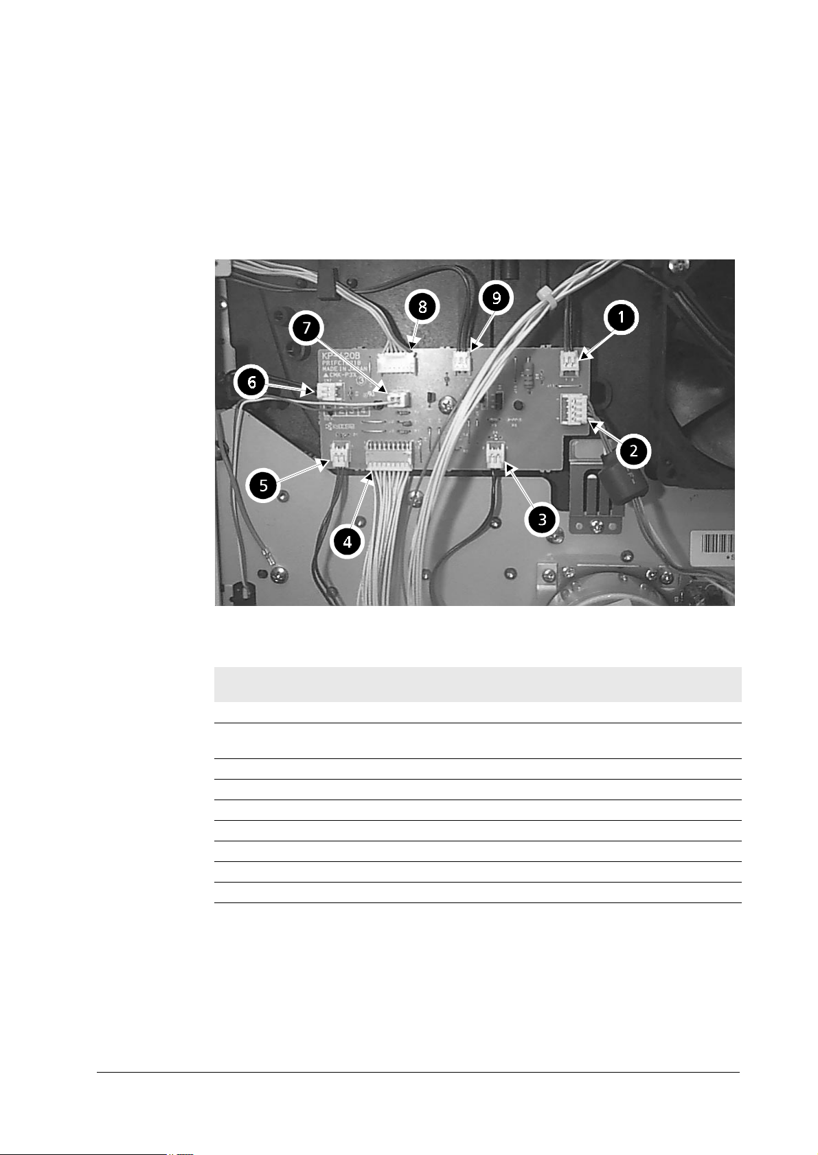
914 %RDUG#OD\RXWV
This section explains the appearance and pin assignment for the printer boards. The wiring
information for these boards is on
/LDLVRQ#ERDUG#.30953
915#2YHUDOO#ZLULQJ#GLDJUDP
7URXEOHVKRRWLQJ
%RDUG#OD\RXWV
, page 6-5.
7DE OH #91#4## .30953#FRQQHFWRUV
/RF1#
DERYH
1 CN8 Fan (large) —
2 CN3 Main motor E1, pin 3 (MOTOR*)/pin 1
3 CN4 Registration clutch —
4 CN1 Engine board KP616/CN14
5 CN5 Feed clutch —
6 CN7 Manual feed clutch —
7 CN9 Cassette detect switch —
8 CN2 Front panel —
9 CN6 Manual feed solenoid —
&RQQHFWRU &RQQHFWHG#WR= &KHFN#SRLQWV
(+24 V)
6-2
)609<33
Page 3
7URXEOHVKRRWLQJ
%RDUG#OD\RXWV
6FDQQHU#LQWHUIDFH#ERDUG#.30955
7DE OH #91#5## &146#+6FDQQHU#&14,#SLQ#DVVLJQPHQW
3LQ#1R1 6LJQDO
1+5 V
2 GND
3 LONB
4LASER
5 VDOUT+
6 VDOUT7PD
8 SCCLK
9 SCRDY*
10 SCANNER*
11 GND
12 +12 V
)609<33
6-3
Page 4
7URXEOHVKRRWLQJ
4;
%RDUG#OD\RXWV
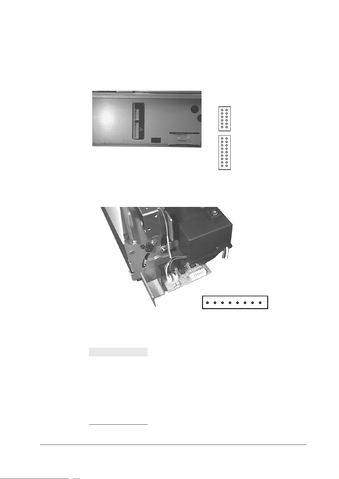
&RQQHFW#ERDUG#FRQQHFWRU2.30949
The two connectors at the right side of the pr inter a re mo un ted on th e con nect board . These con nectors derive engine signals. For pin assignments, refer to
page6- 5.
915#2YHUDOO#ZLULQJ#GLDJUDP
45
&146#+IRU#ODVHU#VFDQQHU#XQLW,
4445
45
&147#+IRU#.30953#ERDUG,
4:4;
,
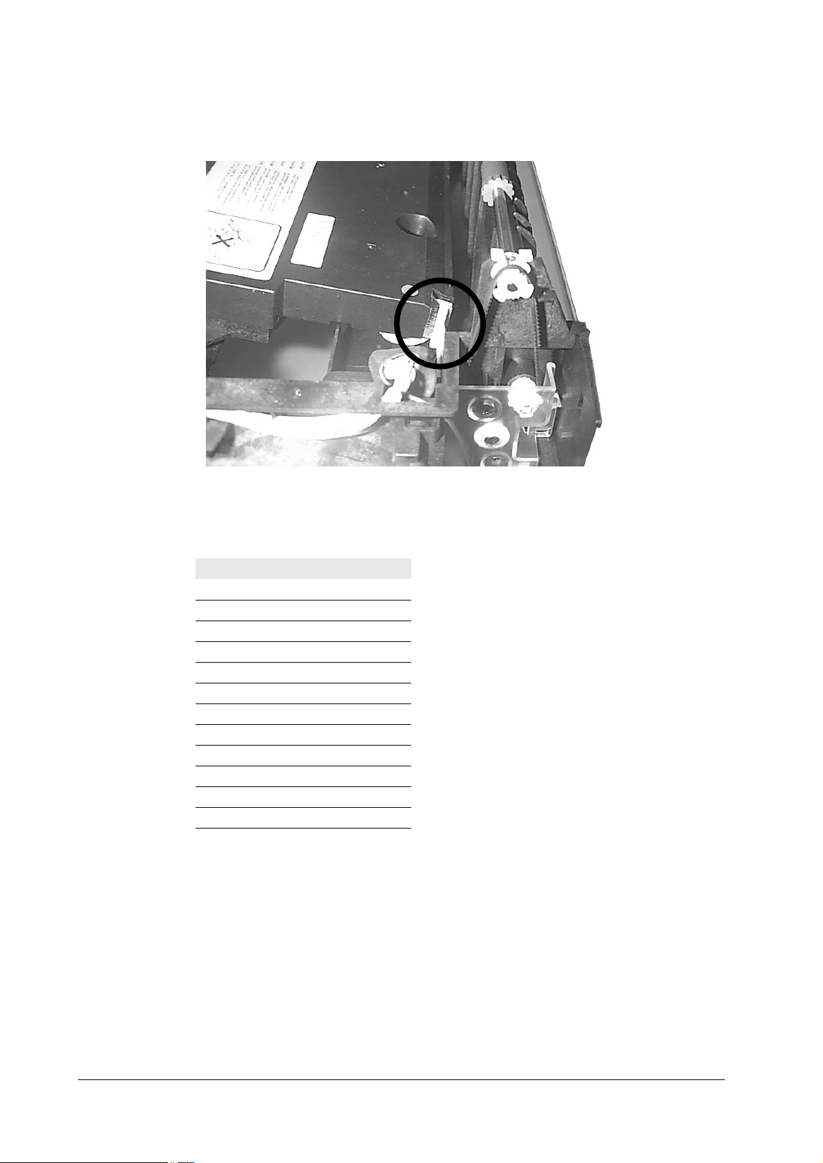
)XVHU#ERDUG#.308382<&0:54
7DE OH #91#6## <&0:54
3LQ#1R1 6LJQDO
1FUPSD*
2+24 V
3 FDNSD*
4 PFULL*
5 THERM*
6EXITJ*
7 GND
8+5 V
6-4
)609<33
Page 5
7URXEOHVKRRWLQJ
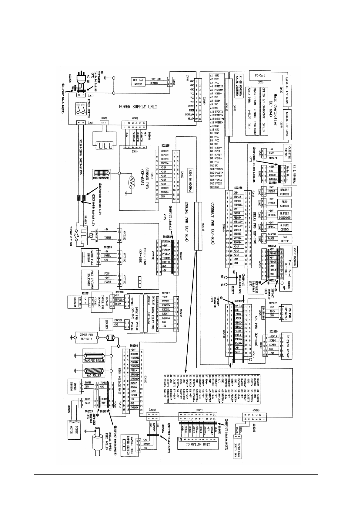
2YHUDOO#ZLULQJ#GLDJUDP
915 2YHUDOO#ZLULQJ#GLDJUDP
)609<33
6-5
Page 6

916 'LDJQRVWLF
The printer automatically executes its self-diagnostic test when it is p owered up (displaying
Self-test
When the printer locates the error with a specific item, it calls for operator*s attention by showing the appropriate message on the operator panel display.
The diagnostic test is done on the following systems simultaneously:
•
•
Flowcharts on the following pages show the order and the items diagnosed in each system.
1RWH 'LDJQRVWLF#WHVW#LV#FDQFHOOHG#LI#RQH#RI#WKH#XVHU0DFFHVVLEOH#FRYHUV#
). The sequence and the items to be diagnosed are explained below.
Engine system (E errors)
Controller system (F errors)
LV#RSHQHG#GXULQJ#WKH#WHVW1
7URXEOHVKRRWLQJ
'LDJQRVWLF
6-6
)609<33
Page 7
7URXEOHVKRRWLQJ
'LDJQRVWLF
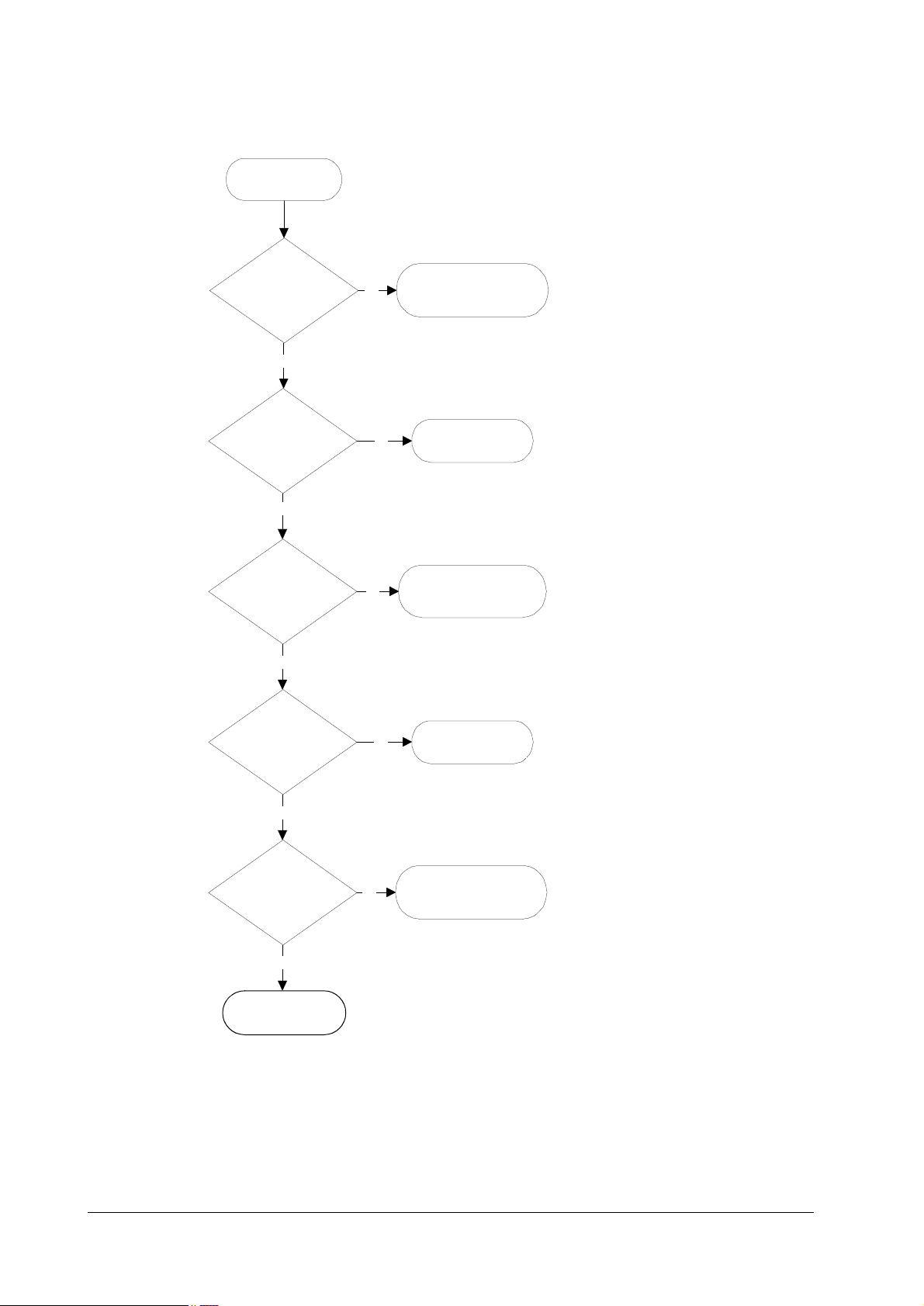
(QJLQH#GLDJQRVWLFV#IORZ
4
3RZHU#RQ
5
(QJLQH#520#FKHNVXP#
2."
<HV
6
)XVHU#WKHUP LVW R U#2."
7KH#KHDWHU#ODPS#LV#WXUQHG#RQ1#
<HV
7KH#VFDQQHU#SRO\JRQ#PRWRU #UHYROYHV1
7
3RO\JRQ#PRWRU#2."
7KH#SRO\JRQ#PRW RU#VWRSV#UHYROYLQJ1#
<HV
7KH#PDLQ#PRWRU#UHYROYHV1#
7KH#HUDVHU#DUUD\#WXUQV#RQ1#
7KH#HUDVHU#DUUD\##WXUQV##RII1
8
0DLQ#PRWRU#2."
(UDVHU#DUUD\#2."
1R
1R
(9#0#(QJLQH#520#HUURU
1R
1R
<
;
<
43
(7#0#)XVHU#HUURU
44
43
(5#0#3RO\JRQ#PRWRU#
HUURU
44
45
(8#0#(UDVHU#HUURU
(4#0#0DLQ#PRWRU#HUURU
#
)609<33
<HV
7KH#HUDVHU#DUUD\#WXUQV#RII1
9
+HDWHU#WHPSHUDWXU H
0DLQ#PRWRU#2."
###########2."
7KH#PDLQ#PRWRU#WXUQV#RII1
<HV
:
:
(QJLQH#LV#UHDG\1
+HDWHU#WHPSHUDWXUH#
2."
7KH#PDLQ#PRWRU#WXUQV#RII1
<HV
;
(QJLQH#LV#UHDG\1
1R
1R
45
46
(4#0#0DLQ#PRWRU#HUURU
(7#0#+HDWHU#HUURU
47
(7#0#+HDWHU#HUURU
6-7
Page 8
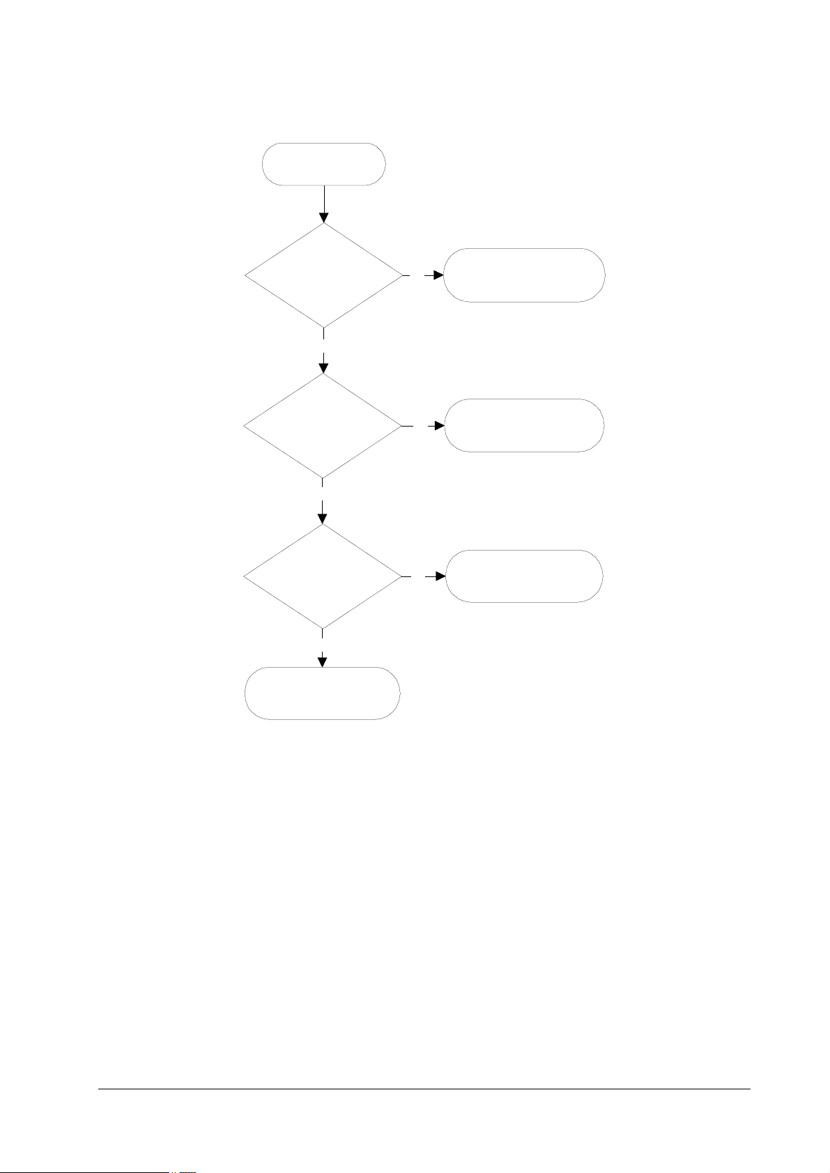
/RJLF#FRQWUROOHU#GLDJQRVWLFV#IORZ
4
3RZHU#RQ
7URXEOHVKRRWLQJ
'LDJQRVWLF
5
6\VWHP#520#FKHNVXP#
2."
<HV
6
&RPPXQLFDWLRQ#
HVWDEOLVKHG#EHWZHHQ#
HQJLQH#DQG#PDLQ#
&38V"
<HV
7
6\VWHP#PHPRU\#2."
<HV
1R
1R
1R
9
)4#0#6\VWHP#520#HUURU
:
(3#0#&RPPXQLFDWLRQ#
HUURU
;
)5#0#6\VWHP#PHPRU\#
HUURU
8
&RQWUROOHU#LV#UHDG\1
For details on how to react to the results of diagnostics, refer to section Service errors on page 6-
15.
6-8
)609<33
Page 9

7URXEOHVKRRWLQJ
*HQHUDO#HUURU#KDQGOLQJ
917 *HQHUDO#HUURU#KDQGOLQJ
3ULRULW\
Each error message has a priority over the others. Thus, if two or more erro r messages are give n
simultaneously, the error message having the highest priority is shown. The priority is as follows (from the highest to the lowest):
7DE OH #91#7## 0HVVDJH#SULRULW\
(UURU#PHVVDJH &DWHJRU\ 5HPDUNV
&DOO#VHUYLFH#SHUVRQ#)3 Service error See page 6-32
,2)#RFFXSLHG —
7RS#FRYHU#RSHQ User-recoverable error See page 6-34
3DSHU#IHHG#XQLW#RSHQ User-recoverable error See page 6-33
6LGH#FRYHU#RSHQ User-recoverable error See page 6-35
2SW1#)HHGHU#4#+5,#UHDU#
FRYHU#RSHQ
'XSOH[#XQLW#UHDU#FRYHU#
RSHQ
5HSODFH#7RQHU2&OHDQ#
SULQWHUE
0LVVLQJ#:DVWH0WRQHU#
ERWWOH
5HSODFH#:DVWH0WRQHU#
ERWWOH
&OHDQ#SULQWHU23UHVV#
&217,18(
3DSHU#MDPE User-recoverable error
)DFH0GRZQ#WUD\#SDSHU#
ILOO
0(025<#&$5'#HUU#,QVHUW#
DJDLQ
,QVHUW#WKH#VDPH#
0(025<#&$5'
3ULQW#&DQFHO" —
0HPRU\#RYHUIORZ#111#
3UHVV#&217,18(
3ULQW#RYHUUXQ#111#
3UHVV#&217,18(
.3'/#HUURU#111#3UHVV#
&217,18(
0(025<&$5'#HUU#111#
3UHVV#&217,18(
2SW1#520#HUURU#111#
3UHVV#&217,18(
6HW#SDSHU23UHVV#
&217,18(
/RDG#SDSHU User-recoverable error
$GG#SDSHU User-recoverable error
User-recoverable error with PF-26 feeder
User-recoverable error with DU-25 duplexer
User-recoverable error
User-recoverable error See page 6-36
User-recoverable error
User-recoverable error
User-recoverable error
User-recoverable error
User-recoverable error
User-recoverable error
User-recoverable error
User-recoverable error
User-recoverable error
User-recoverable error
User-recoverable error
)609<33
6-9
Page 10

7DE OH #91#7## 0HVVDJH#SULRULW\
(UURU#PHVVDJH &DWHJRU\ 5HPDUNV
6HOI#WHVW —
6OHHSLQJ —
3OHDVH#ZDLW —
3-/#2306*26706* —
3URFHVVLQJ —
:DLWLQJ —
)RUP)HHG#7LPH2XW —
2SWLRQ#LQWHUIDFH#(UURU User-recoverable error
7RQHU#ORZ#7.0532&OHDQ#
SULQWHU
:DUQLQJ2/RZ#PHPRU\ -
%DWWHU\#HUURU20(025<#
&$5'
)RUPDW#HUURU20(025<#
&$5'
:DUQLQJ#EDWWHU\2
0(025<#&$5'
5HDG\ —
7URXEOHVKRRWLQJ
*HQHUDO#HUURU#KDQGOLQJ
User-recoverable error
User-recoverable error
User-recoverable error
User-recoverable error
6-10
)609<33
Page 11
7URXEOHVKRRWLQJ
8VHU0UHFRYHUDEOH#HUURUV
918 8VHU0UHFRYHUDEOH#HUURUV
User-recoverable errors do not normally require a service call unless the suggested remed y does
not solve them. The instructions below indicate how to respond to problems indicated by the
operator panel symbolic indicators and by the panel display.
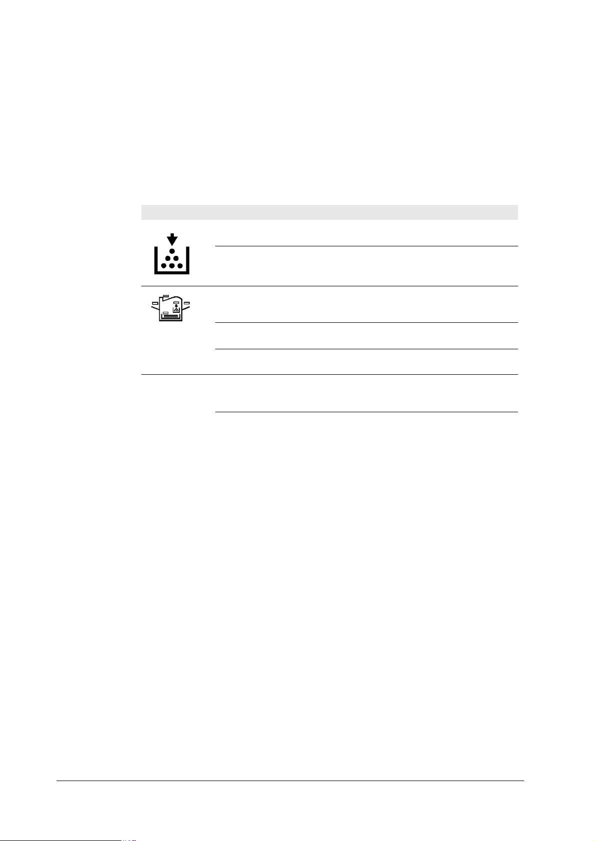
7DE OH #91#8## 8VHU0UHFRYHUDEOH#HUURUV
$77(17,21
6LGH#FRYHU#2SHQ Open the side cover, then close tightly.
3DSHU#IHHG#XQLW#2SHQ Open the paper feed unit, then close tightly.
)DFH0GRZQ#WUD\#SDSHU#IXOO The face-down tray has become full (approx. 250 pages).
$GG#SDSHU Add paper to the paper cassette or multi-purpose tray.
6HW#SDSHU23UHVV#&217,18( Add a sheet of paper to the multi-purpose tray (manual
/RDG#SDSHU#SDSHUVL]H The paper size does not match. The size of the paper in the
3DSHU#MDP Open the top cover or the paper feed un it and correct the
:DUQLQJ#ORZ#PHPRU\ The printer’s internal memory is running low due to the
,QGLFDWLRQ &RUUHFWLYH#DFWLRQ
Flashing The printer has run low on toner. The toner should be
replaced as soon as possible.
Lit Install a new toner kit. See chapter 1.
Fast flashing There is a paper jam. There is a possibility tha t paper may be
jammed at the point i ndicated by flashing, open and remove
any jammed paper.
Slow flashing The paper has run out in the paper cassette or multi-purpose
tray. Please insert paper.
Lit This indicates either the current paper feeder or the paper
output point.
Flashing The printer has insufficient memory available or the printer
is warming up (Pleasewait). Conf irm the message indicated
on the message display.
Lit Note the maintenance message on the message display and
consult Table
Remove all printed pages from the face-down tray. When
the printer senses that the face-down tray is empty again, it
will continues printing into the face-down tray.
mode), and press the CONTINUE key.
cassette is different to the size specified by the appl ication
software or by PRESCRIBE II. Either put paper of the specified size into the cassette. See Section 1.4.If the CONTINUE key is pressed, printing will be resumed. However, if
more than one sheet is to be printed, the same message will
again be displayed from the second sheet onward. It is also
possible to abandon printing by pressing the CANC EL key.
paper jam (or paper mis-feeding in the cassette). See Section
number of fonts and m acro s down load ed. Pr int a st atus pag e
to see how much us er m emo ry is lef t, an d t ry del eti ng un necessary fonts and macros. See the PRESCRIBE II DELF and
DELM commands explanation in the programming man ual
(CD-ROM).
)609<33
6-11
Page 12

7DE OH #91#8## 8VHU0UHFRYHUDEOH#HUURUV
,QGLFDWLRQ &RUUHFWLYH#DFWLRQ
7RQHU#ORZ#7.0532&OHDQ#
SULQWHU
5HSODFH#7RQHU2&OHDQ#SULQWHU Replace the toner container using a new toner kit. The
&OHDQ#SULQWHU113UHVV#&210
7,18(
5HSODFH:DVWH0#WRQHU#ERWWOH Replace the old waste tone r bottl e with the n ew one whic h is
0LVVLQJ#:DVWH0WRQHU#ERWWOH Install the waste toner bottle. The printer does not operate
0HPRU\#RYHUIORZ113UHVV#&210
7,18(&217
3ULQW#RYHUUXQ113UHVV#&210
7,18(
0(025<#&$5'#HUU2,QVHUWDJDLQ The memory card is accidentally removed from the pr inter’s
,QVHUW#WKH#VDPH#0(025<#&$5' You have inserted the wrong memory card when the Inserta-
)RUPDW#HUURU#0(025<#&$5' This message appears when the printer is in the ready state
:DUQLQJ#EDWWHU\#0(025<#&$5' This message appears when the printer is in the ready state
0(025<#&$5'#HUU2#&&113UHVV#
&217,18(
7URXEOHVKRRWLQJ
8VHU0UHFRYHUDEOH#HUURUV
Replace the toner container usi ng a new toner kit. See Section
printer does not op erat e when th is m essage is disp la yed . S e e
section
Please clean the inside of the printer. See Sect i on ...This
message will be displ a yed when replacing the toner container after the message ReplaceTonerCleanprinter has been
displayed. After cleaning the inside of the printer, press the
CONTINUE key and the printer will be ready for printing.
included in the TK-20/TK-20H toner kit. The message will
also be shown if the waste toner bottle has become full. The
waste toner bottle should be rep laced when the message display eventually shows TonerlowTK-20Cleanprinter.
when this message is displayed.
The total amount of data received by the printer exceeds the
printer’s internal memory. Try adding more memory (expansion RAM). Press the CONTINUE key to resume printing.
You can abandon printing by the CANCEL key.
The data transferred to the printer was too complex to print
on a page. Press the CONTINUE key to resume printin g.
(The page may bre ak in s ome pages .)Yo u can a ban don p rinting by the CANCEL key.Note: After this message has been
displayed, Page protect mode will be On. To maintain optimum use of memory dur ing printing, disp lay >Pageprotect
from the control panel, and re-select Auto.See the printerís
userís manual.
memory card slot during reading. If you continue reading the
memory card, insert the same memory card into the slot
again. The printer again reads it from the beginning of the
data.Note: We recommend that you follow the reading procedure from the beginning to ensure cor rect reading of th e
memory card.
gain message was display ed. Remove the wrong memor y
card from the printer’s memory card slot and insert th e correct memory card. The printer again reads it from the beginning of the data.
and the memory card is not formatted, and therefore cannot
be read or written. Follow th e pro ced ure on Se c tion ... to format the card.
and the battery in the m emory card is l ow. You can sti ll enter
the memory card mode, but the battery should be changed as
soon as possible.
This message appears when an error occurs during access to
the memory card using the PRESCRIBE II ICCD command
or from the printer’ s control panel (codes 09 and 11 only).
The error is indicated by one of the numbers ## listed under
the Memory card errors which follows.
6-12
)609<33
Page 13

7URXEOHVKRRWLQJ
8VHU0UHFRYHUDEOH#HUURUV
7DE OH #91#8## 8VHU0UHFRYHUDEOH#HUURUV
>Read fonts Failed The amount of memory availabl e for the fonts header parts
I/F occupied This message is displayed when you attempt to use the
Processing PAR FIT A4 FIT (image FITting) flashes to indicate that a loss of raster
Processing PAR 600 A4ÍProcessing
PAR 300 A4
>Read fonts Failed The amount of memory availabl e for the fonts header parts
,QGLFDWLRQ &RUUHFWLYH#DFWLRQ
of font is too small to load more fonts. Try de le tin g unn ecessary fonts and macros.
printer’s control panel to change the environmental settings
on the interface from which data are presently being
received.
data occurred when the data was compressed to be fitted
within the currently available memory. Flashing FIT extinguishes automatically when the job times out; the printer
receives the next data from the host computer; or if you press
any key on the printer ’s control panel. Try adding more
memory in the printer to prevent this error.
Change of the resolution indicator from 600 to 300 (flashing) means that the job in 600-dpi resolu tio n wa s not able to
run within the currently available memory. The resolution
reverts to 600 dpi automatical ly whe n the job times out; the
printer receives the next data from the host computer; or if
you press any key on the printer’s control panel. Try adding
more memory in the printer to prevent this error.
of font is too small to load more fonts. Try de le tin g unn ecessary fonts and macros.
0HPRU\#FDUG#HUURUV
7DE OH #91#9## 0HPRU\#FDUG#HUURUV
(UURU#
FRGH
01 SRAM Card size error (An attempt was made to write data of greater than 16 MB
02 SRAM No memory card inserted. Insert a proper memory card.
03 SRAM/flash Non PCMCIA card. Replace the card with a PCMCIA card.
04 SRAM Not RAM card. Use a SRAM-type card if you want to write data to an
05 SRAM Memory card battery error. Replace the memory card’s internal battery
06 SRAM Memory card protect error. Release the write protection on the memory
07 SRAM Non-Kyocera format. Reformat the memory card using MODE SELECT
08 SRAM Partition name error. Follow instructions given attempt in Chapter 2 to
09 SRAM Memory card data full error (An attempt was made to write data exceed-
$SSOLFDEOH#
FDUG#W\SH
0HDQLQJ
in size.). Reduce the size of the data to be wr itten fro m th e host co mpu te r
to 16 MB or less; or, a file name could not be found in the memory card.
memory card.
with a new one.
card when you write data to the memory card.
(See the printer’s User’s Manual).
properly name the destin ati on .
ing the capacity of the memory card). Abandon the writing operation on
the host computer first. Press CONTINUE key; when the message turns to
Waiting, press FORM FEED key (Ready).
)609<33
6-13
Page 14

7DE OH #91#9## 0HPRU\#FDUG#HUURUV
7URXEOHVKRRWLQJ
8VHU0UHFRYHUDEOH#HUURUV
(UURU#
FRGH
10 - Reserved
11 SRAM Data name full (An attempt was made to write more than 127 destination
12 - Reserved
13 Flash Erase logic error with flash memory card. Try replacing the memory card.
14 - Reserved
15 Flash Non PCMCIA flash card. Repl ace the card with a PCMCIA flash card.
16 - Reserved
17 Flash Unable to write to the flash memory card due to insufficient printer mem-
18 Flash Writing error. Try replacing the memory card.
19 - Reserved
$SSOLFDEOH#
FDUG#W\SH
0HDQLQJ
data names). Press CONTINUE key (Ready).
ory. Either delete unnecessary macros or fonts stored in the printer, or
extend the printer’s available memory.
For details on memory card availability, see section Prin ter specifications in chapter 1.
6-14
)609<33
Page 15

7URXEOHVKRRWLQJ
6HUYLFH#HUURUV
919 6HUYLFH#HUURUV
7DE OH #91#:## 6HUYLFH#SHUVRQ#HUURUV
The printer does not operate when a message beginning with E, F, or C is displayed. The total
numer of pages printed is also indicated. The message is categorized as follows:
0HVVDJH &RUUHFWLYH#DFWLRQ
Call service person En:123456 Mechanical error (n=0, 1, 2, ...). Follow the appropriate instruc-
tions provided in this section.
Call service person Fn:123456 Controller error (n=0, 1, 2, ...). Follow the appr opriate instruction s
provided in this section.
Call service person Cn: 123456 Option equipment error (n=0, 1, 2, ...). This message pertains to
either the sorter or duplexer. C1 through C3 are relevant to the
duplexer; C4 through C6 to the sorter. See the service manual
appropriate to the option used with the printer.
Call service person Dn: 123456 Engine firmware download error (n=0, 1, 2, ...). See section
Updating the engine firmware in chapter 3.
)609<33
6-15
Page 16

(3³&RPPXQLFDWLRQ#HUURU
7DE OH #91#;## (3#HUURU
Communication between the
engine cont r ol ler and the main
controller is failed.
(4³0DLQ#PRWRU#HUURU
7DE OH #91#<## (4#HUURU
The main motor is overtorqued. • Overcurrent in the main motor
7URXEOHVKRRWLQJ
6HUYLFH#HUURUV
0HDQLQJ 6XJJHVWHG#FDXVHV &RUUHFWLYH#DFWLRQ
• Controller gate array defect
• Connector failure be tween the
engine and the main controller
• Overrun in the eng ine s yst em,
deactivating the progam flash
ROM
0HDQLQJ 6XJJHVWHG#FDXVHV &RUUHFWLYH#DFWLRQ
circuitry due to an axcessive
torque
• Loose connector to mot or
• Defective gate array on the
engine board
• No response from the main
motor due to the defective
motor driver (transistor)
• Defective overcurrent detector
(transistor)
Verify connector connections.
Replace the engine board and/or
the main controller board.
Follow the flow chart on page 617, Figure 6.1 and the following.
6-16
)609<33
Page 17

7URXEOHVKRRWLQJ
6HUYLFH#HUURUV
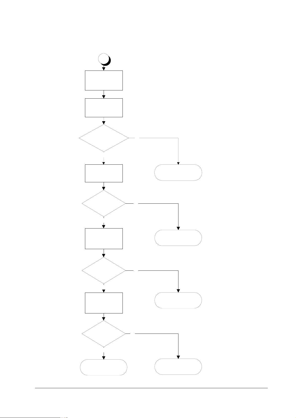
)LJXUH#914 (4#HUURU
(4
+0DLQ#PRWRU#HUURU,
&RQQHFW#WHVWHU#WR#&6#
RI#&14#RI#PRWRU1
7XUQ#SULQWHU#SRZHU#
RII/#WKHQ#RQ#DJDL1#
3ULQW#D#VWDWXV#SDJH1
,V#&6+02725-,#RI#
&14#RI#PRWRU#/"
<HV
,V#&4#RI#&14#RI#PRWRU#
.579"
<HV
7XUQ#SULQWHU#SRZHU#
RII/#WKHQ#RQ#DJDLQ1#
3ULQW#D#VWDWXV#SDJH
1R
1R
&RQQHFW#WHVWHU#WR#&6#
RI#&16#RI#.309531
4
7XUQ#SULQWHU#SRZHU#
RII/#WKHQ#RQ#DJDLQ1#
3ULQW#D#VWDWXV#SDJH1
,V#&6#+02725-,#
RI#&16#RI#.30953#
/"
<HV
5HSODFH#KD UQHVV#
63558<#EHW1#PRWRU#
DQG#.309531
1R
6
)609<33
'RHV#PRWRU#FORFN#DSSHDU#
DW#&7#RI#&14#RI#PRWRU"
<HV
5
1R
5HSODFH#GULYHU#XQLW1
6-17
Page 18
)LJXUH#915 (4#HUURU³&RQWLQXHG
4
&RQQHFW#WHVWHU#WR#&7#
RI#&16#RI#.309531
7XUQ#SULQWHU#SRZHU#
RII/#WKHQ#RQ#DJDLQ1#
3ULQW#D#VWDWXV#SDJH1
7URXEOHVKRRWLQJ
6HUYLFH#HUURUV
'RHV#PRWRU#FORFN#
DSSHDU#DW#&7#RI#&16#
RI#PRWRU"
<HV
7XUQ#SULQWHU#SRZHU#
RII/#WKH#RQ#DJDLQ1#
3ULQW#D#VWDWXV#SDJH1
'RHV#PRWRU#FORFN#DSSHDU#
DW#&43#RI#&14#RI#.30953"
<HV
7XUQ#SULQWHU#SRZHU#
RII/#WKHQ#RQ#DJDLQ1#
3ULQW#D#VWDWXV#SDJH1
'RHV#PRWRU#FORFN#DSSHDU#
DW#&43#RI#&147#RI#
.30949"
1R
5HSODFH#KDUQHVV#EHW1#
PRWRU#DQG#.30953#
+63558<,1
1R
5HSODFH#.30953#
ERDUG1
1R
<HV
&RQQHFW#WHVWHU#EHW1#
&43#RI#&147#RI#
.30949#DQG#&79#RI#
&154#RI#.309471
&RQGXFWHG"
<HV
5HSODFH#.309471
1R
5HSODFH#KDUQHVV#EHW1#
6-18
.30953#DQG#.309491
5HSODFH#.30949#
ERDUG1
)609<33
Page 19

7URXEOHVKRRWLQJ
6HUYLFH#HUURUV
)LJXUH#916 (4#HUURU³&RQWLQXHG
)609<33
6-19
Page 20

)LJXUH#917 (4#HUURU³(QG
7URXEOHVKRRWLQJ
6HUYLFH#HUURUV
6-20
)609<33
Page 21

7URXEOHVKRRWLQJ
6HUYLFH#HUURUV
7DE OH #91#43##(5#HUURU
(5³/DVHU#VFDQQHU#PRWRU#HUURU
0HDQLQJ 6XJJHVWHG#FDXVHV &RUUHFWLYH#DFWLRQ
The polygon motor does not
deliver a synchronous output (L)
within the predetermined period
of time.
• Timeout in the predetermined
period of lead time which the
scanner motor speed has to be
reached at start up (SCRDY*)
• Connector insertion er ror
• Defective gate array on the
engine board
• Time out dur to the defective
scanner motor driver (transistor)
Follow the flow chart on the next
page.
)609<33
6-21
Page 22

)LJXUH#918 (5#HUURU
7URXEOHVKRRWLQJ
6HUYLFH#HUURUV
6-22
)609<33
Page 23

7URXEOHVKRRWLQJ
6HUYLFH#HUURUV
)LJXUH#919 (5#HUURU³&RQWLQXHG
Are #5-9 of CN22
of KP-614 +24V?
)609<33
6-23
Page 24

)LJXUH#91: (5#HUURU³(QG
7URXEOHVKRRWLQJ
6HUYLFH#HUURUV
6-24
)609<33
Page 25

7URXEOHVKRRWLQJ
6HUYLFH#HUURUV
7DE OH #91#44##
(6#0#/DVHU#EHDP#GHWHFWLRQ#HUURU
0HDQLQJ 6XJJHVWHG#FDXVHV &RUUHFWLYH#DFWLRQ
Beam detection is failed. The
photo detector boa r d do es no t
deliver a synchronous output (L).
• No beam hit due to the laser
diode defect (PD*)
• Improper connector insertion
• Soiled/defective bea m dete ctor (pin-photo diode) sensor
• Defective safety lock
• Unoperative gate array input
port
Follow the flow chart on the next
page.
)609<33
6-25
Page 26

)LJXUH#91; (6#HUURU
7URXEOHVKRRWLQJ
6HUYLFH#HUURUV
6-26
)609<33
Page 27

7URXEOHVKRRWLQJ
6HUYLFH#HUURUV
)LJXUH#91< (6#HUURU³&RQWLQXHG
)609<33
6-27
Page 28

(7#0#)XVHU#KHDWHU#HUURU
7DE OH #91#45##(7#HUURU
The fuser heater is not intact due
to disconnection or the circuit failure.
7URXEOHVKRRWLQJ
6HUYLFH#HUURUV
0HDQLQJ 6XJJHVWHG#FDXVHV &RUUHFWLYH#DFWLRQ
• Blown-out thermistor
• Improper connector insertion
• Blown-out haloge n hea te r
• Blown-out thermostat
• Comparator defe ct on the
engine board
• Defective engine CPU (input
port)
• Defective gate array (input/
output port operatio n)
Follow the flow chart on the next
page.
6-28
)609<33
Page 29

7URXEOHVKRRWLQJ
6HUYLFH#HUURUV
)LJXUH#9143 (7#HUURU
)609<33
6-29
Page 30

(8³(UDVHU#HUURU
7DE OH #91#46##(8#HUURU
The eraser is blown out or the
power supply does no t rea ch to
the eraser .
)LJXUH#9144 (8#HUURU
7URXEOHVKRRWLQJ
6HUYLFH#HUURUV
0HDQLQJ 6XJJHVWHG#FDXVHV &RUUHFWLYH#DFWLRQ
• Blown-out LED chip(s)
• Connector insertion error
• Defective gate arra y (input/
output port)
Follow the flow chart on the next
page.
6-30
)609<33
Page 31

7URXEOHVKRRWLQJ
6HUYLFH#HUURUV
7DE OH #91#47##('#HUURU
7DE OH #91#48##(<#HUURU
('³)ODVK#520#HUURU
0HDQLQJ 6XJJHVWHG#FDXVHV &RUUHFWLYH#DFWLRQ
Checksum is erroneous with the
flash ROM.
• Data readout error on the flash
ROM
(<#0#7RQ H U#PRWRU#HUURU
0HDQLQJ 6XJJHVWHG#FDXVHV &RUUHFWLYH#DFWLRQ
The toner motor is overtorqued. • Overcurrent in the toner
motor circuitry due to an
axcessive torque
• Loose connector
• Defective gate array on the
engine board
• Defective toner motor overcurrent detector
Replace the engine board.
Follow the flow chart on the next
page.
)LJXUH#9145 (<#HUURU
)609<33
6-31
Page 32

)3#0#)URQW#FRQWURO#SDQHO#HUURU
7DE OH #91#49##)3#HUURU
Communication is failed between
the front panel and the main controller.
)4#0#6\VWHP#520#HUURU
7DE OH #91#4:##)4#HUURU
Checksum is failed with EPROMs
on the main controller board.
)5#0#0DLQ#PHPRU\#HUURU#
7DE OH #91#4;##)5#HUURU
7URXEOHVKRRWLQJ
6HUYLFH#HUURUV
0HDQLQJ 6XJJHVWHG#FDXVHV &RUUHFWLYH#DFWLRQ
• — Replace the main controller
board. To remove the main controller board, see page 2-9.
0HDQLQJ 6XJJHVWHG#FDXVHV &RUUHFWLYH#DFWLRQ
• - Replace the main controller
board. To remove the main controller board, see page 2-9.
Checksum is failed with the RAM
on the main controller board.
)6#0#*HQHUDO#IDLOXUH#
7DE OH #91#4<##)6#HUURU
Miscellaneous failure with the
main controller, other than F0, F1,
and F3, above.
0HDQLQJ 6XJJHVWHG#FDXVHV &RUUHFWLYH#DFWLRQ
• - Replace the main controller
board. To remove the main controller board, see page 2-9.
0HDQLQJ 6XJJHVWHG#FDXVHV &RUUHFWLYH#DFWLRQ
• - Tu rn printer power off, then on
again. If not solved, replace the
main controller board. To remove
the main controller board, see
page 2-9.
6-32
)609<33
Page 33

7URXEOHVKRRWLQJ
6HUYLFH#HUURUV
)LJXUH#9146 )DOVH#HUURU³)HHG#XQLW#FRYHU#RSHQ
)DOVH#HUURU³)HHG#XQLW#FRYHU#RSHQ
)609<33
6-33
Page 34

)LJXUH#9147 )DOVHU#HUURU³7RS#FRYHU#RSHQ
7URXEOHVKRRWLQJ
6HUYLFH#HUURUV
6-34
)609<33
Page 35

7URXEOHVKRRWLQJ
6HUYLFH#HUURUV
)LJXUH#9148 )DOVH#HUURU³6LGH#FRYHU#RSHQ
)609<33
6-35
Page 36

)LJXUH#9149 )DOVH#HUURU³0LVVLQJ#ZDVWH#WRQHU#ERWWOH
7URXEOHVKRRWLQJ
6HUYLFH#HUURUV
6-36
)609<33
Page 37

7URXEOHVKRRWLQJ
3ULQW#TXDOLW\#SUREOHPV
91: 3ULQW#TXDOLW\#SUREOHPV
Print quality probl ems ra nge from u neven tone t o comple tely blank out put. The troubl eshoo ting
procedure for each type of problem is given below.
&RPSOHWHO\#EODQN#SULQWRXW
&KHFNSRLQW 6XJJHVWHG#UHPHG\
Check the developer unit. • Check that the developer unit is inserted correctly
$OO0EODFN#SULQWRXW
&KHFN#SRLQW 6XJJHVWHG#UHPHG\
Check the main charger unit
installation.
• Check that the developer ’s connector is connect ed properly.
• Open the printer side cover and check that the main charger unit is
correctly seated. To do this, take out the main charger unit from
the printer; then reinstall it carefully.
'URSRXWV/#KRUL]RQWDO#VWUHDN/#EODFN#GRWV
&KHFN#SRLQW 6XJJHVWHG#UHPHG\
Clean the main charger. • Open the side (drum access) cover. Pull out the green knob on the
main charger. Pull and pu sh in seve ral time s. For deta ils, see pa ge
Note the spacing of the defects.
Use the Repetitive defect gauge
on page6-43.
3-5,
6161#&OHDQLQJ#WKH#SULQWHU
• If the defects occur at regular intervals of 60.6 mm, the problem
may be a dirty transfer roller. Clean or replace the tranfer roller.
• If the defects occur at regular intervals of 125.6 mm, the problem
may be a damaged drum unit or fuser roller. Replace the drum
unit or fuser unit accordingly.
• If the defects occur at regular intervals of 39.3 mm, the problem
may be a damaged developing roller. Replace the developer unit,
if necessary (page 5-4,
5HPRYLQJ#WKH#GHYHORSHU#XQLW
.
).
)609<33
6-37
Page 38

7URXEOHVKRRWLQJ
3ULQW#TXDOLW\#SUREOHPV
%ODFN#YHUWLFDO#VWUHDNV#
&KHFN#SRLQW 6XJJHVWHG#UHPHG\
Check the front display for indication of “Toner low. ”
Contaminated main charger wire. • Clean the main charger wire by pulling the green c olored cleaning
• If the display shows that the toner is running out, repl ace the tone r
container with a new one. See page 3-3,
UHSODFHPHQW
knob in and out several times.
.
7RQHU#FRQWDLQHU#
8QVKDUS#SULQWLQJ
&KHFN#SRLQW 6XJJHVWHG#UHPHG\
Check the front display for indication of “Toner low. ”
Check the print density setting. • Operate the operator panel to see if the print density setting is ade-
Check the paper thickness setting. • If thick paper is used, try changing the paper thickness setting.
Check Ecoprint setting • Turn Ecoprint for normal density printing.
The surface of the drum is con-
taminated.
• If the display shows that the toner is running out, repl ace the tone r
container with a new one. See page 3-3.
quate.
See page 3-15,
• See page 6-41.
61:1#6HWWLQJ#WKH#SDSHU#W\SH1
6-38
)609<33
Page 39

7URXEOHVKRRWLQJ
3ULQW#TXDOLW\#SUREOHPV
*UH\#EDFNJURXQG
&KHFN#SRLQW 6XJJHVWHG#UHPHG\
Check the front display for indication of “Toner low.”
Check the main charger unit
installation.
Clean the main charger. • Clean the main charge r wire by pullin g the green colo red cleanin g
• If the display shows that the tone r is running out, repl ace the ton er
container wi th a ne w one . Se e pa g e 3- 3 ,
UHSODFHPHQW
• Open the printer side cover and check that the main charger unit is
correctly seated. To do this, take out the main charger unit from
the printer; then reinstall it carefully.
knob in and out several times.
.
7RQHU#FRQWDLQHU#
'LUW#RQ#WKH#WRS#HGJH#RU#EDFN#RI#WKH#SDSHU
&KHFN#SRLQW 6XJJHVWHG#UHPHG\
Check toner contamination in various parts.
Check the transfer roller. • If the transfer roller is contaminated with toner, clean the transfer
• Dirty edges and back of the pap er can be caused by toner accummulated on such parts as the paper chute, paper transportation
paths, the bottom of the developer unit, and the fuser inlet. Clean
these areas and parts to remove toner.
roller using a vacuum cleaner; or by continuously printing a lowdensity page until the symptom has faded away.
,QFRUUHFW#SULQWLQJ#UHJLVWUDWLRQ
&KHFN#SRLQW 6XJJHVWHG#UHPHG\
Wrong application manipulation • Check driver setting. If using Prescribe commands, review that
the proper syntax is followed.
Check the paper size sensor in the
paper cassette.
• Check switches on KP-614 and KP-616 boards. Refer to the following section.
)609<33
6-39
Page 40

&KHFNLQJ#FDVVHWWH#VL]H#VHQVRUV
The printer tells the size of paper (cassette) to be fed by means of sensors on the KP-614 and
KP-616 boards. These sensors (swit ches) are activated by the pushing peg s on paper cassettes i n
different paper sizes. If the sensors are not correctly activated in a correct matrix of activation,
paper jam or printing defects like above may occur.
)LJXUH#914: &DVVHWWH#VL]H#VHQVRUV
➍
#+/HWWHU,
➍
7URXEOHVKRRWLQJ
3ULQW#TXDOLW\#SUREOHPV
&RQWUROOHU
ER[#WRS#FRYHU
#+$7,
➊➋➌
7DE OH #91#53##3DSVHU#VL]H#PDWUL[
3DSHU#VL]H
A4L Off Off On On
Letter L Off On On On
B5 On Off Off Off
Legal size On On Off Off
A5 Off Off Off On
B4 On Off On Off
A3 Off Off On Off
Ledger Off On On Off
No cassette Off Off Off Off
)URQW#VLGH
6ZLWFK#,'#+6HH#DERYH1,
➊➋➌➍
6-40
)609<33
Page 41

7URXEOHVKRRWLQJ
3ULQW#TXDOLW\#SUREOHPV
'UXP#FOHDQLQJ
This mode is meant to provide a manual means of drum cleani ng in additioin to the regular
cleaning procedure made automatically in a photographics cycle. In this mode, the drum turns
for the period of approximately three minutes with no main charging dispersed over the drum.
Since the cleaning blade in the drum continuously attempt to scrape soils and paper dust on its
surface, the drum can be brought in a clean state.
To clean the drum using this feature, peform the following:
Press
4
Press . repeatedly until
5
Press !.
6
Press + repeatedly until
7
Press >. The display should show
8
Press + the display should show
9
Press
:
Press
;
.
02'(
Others>
>Service>
. The display should show “?.”
(17(5
. The drum then starts turning and stops after approx. 3 minutes.
(17(5
is indicated.
is indicated.
>>Developer
>>Drum
.
.
The printer reverts to
Ready
.
)609<33
6-41
Page 42

This page left blank intentionally
7URXEOHVKRRWLQJ
3ULQW#TXDOLW\#SUREOHPV
6-42
)609<33
 Loading...