

Page 1

&KDSWHU#5 ,167$//$7,21
&RQWHQWV
514 8QSDFNLQJ/#SDJH#50#5
515 ,QVWDOOLQJ#WRQHU/#SDJH#50#6
,QVWDOOLQJ#WKH#ZDVWH#WRQHU#ERWWOH/#SDJH#508
516 'HYHORSHU#LQLWLDOL]DWLRQ/#SDJH#50#9
517 ([SDQGLQJ#PHPRU\/#SDJH#50#:
0LQLPXP#PHPRU\#UHTXLUHPHQWV/#SDJH#50:
6,00#WR#EH#XVHG/#SDJH#50:
1RWHV#RQ#KDQGOLQJ#WKH#PDLQ#FLUFXLW#ERDUG#DQG#6,00V/#SDJH#50:
5HPRYLQJ#WKH#PDLQ#FLUFXLW#ERDUG/#SDJH#50:
,QVWDOOLQJ#6,00V/#SDJH#50<
7HVWLQJ#WKH#H[SDQVLRQ#PHPRU\/#SDJH#5043
518 8VLQJ#WKH#&RQWURO#3DQHO/#SDJH#50#44
,QGLFDWRUV/#SDJH#5044
)URQW#SDQHO#NH\V/#SDJH#5045
0RGH#VHOHFWLRQ#PHQX/#SDJH#5045
6HUYLFH#PRGH/#SDJH#5045
Page 2

514 8QSDFNLQJ
The following diagrams show how to unpack the printer in the shipping carton. While unpacking the printer, check that the parts shown below are all present.
,QVWDOODWLRQ
8QSDFNLQJ
7RQHU#NLW
+7.053,
)LOOHUV
0DQXDOV
'HYHORSHU
FRQWDLQHU
3RZHU
FDEOH
)609<33
SULQWHU
2-2
)609<33
Page 3
,QVWDOODWLRQ
,QVWDOOLQJ#WRQHU
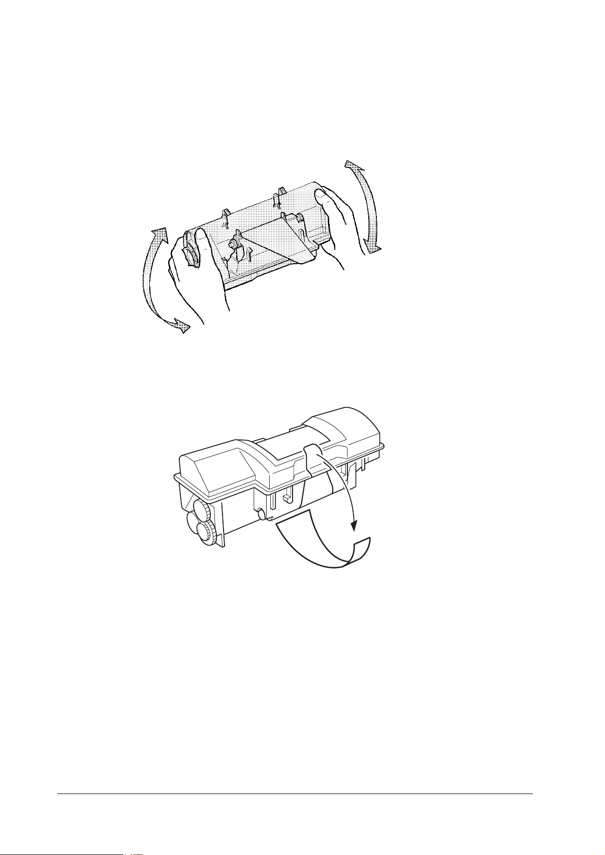
515 ,QVWDOOLQJ#WRQHU
Take the toner container from the toner kit (TK-20) supplied with the printer. Give it a good
shake (5 to 6 times).
Peel off the seal on the bottom of the toner container by carefully pulling off.
)609<33
2-3
Page 4

,QVWDOODWLRQ
,QVWDOOLQJ#WRQHU
Insert the toner container in the printer as below. Align the two locating pins at the bottom of the
container with the mating holes in the developer unit.
&DXWLRQ 7R#DYRLG#WURXEOH#+WRQHU#VSLOOLQJ/#HWF1,/#WKH#WRQHU#FRQWDLQHU#PXVW#EH#FRU0
UHFWO\#VHDWHG#DQG#ORFNHG#LQ#WKH#SULQWHU1#7R#GR#WKLV/#SUHVV#WKH#IDU#VLGH#RI#
WKH#FRQWDLQHU#DW#WKH#OHIW#DQG#ULJKW#386+#+(5(#PDUNV#XQWLO#D#FOLFN#LV#
KHDUG1
2-4
)609<33
Page 5

,QVWDOODWLRQ
,QVWDOOLQJ#WRQHU
,QVWDOOLQJ#WKH#ZDVWH#WRQHU#ERWWOH
The waste toner bottle is also supplied. It must be installed inside the drum access door in the
left side of the printer. Open the drum access door and install it as shown.
:DVWH#WRQHU#ERWWOH
)609<33
2-5
Page 6

516 'HYHORSHU#LQLWLDOL]DWLRQ
The printer is shipped from the factory with no toner supplied in its developer unit. When the
printer is first switched on after the toner container is installed in the mann er above, there wi ll
be a delay of several minutes before the printer gets ready to print a job.
This delay is necessary for the printer to fill the developer reservoir with a sufficient amount of
toner to continuously support a print job. The period of time for this delay is approximately 10
minutes
Since the automatic implementation of the developer initialization is done only once at first
switching power on, if a new developer is installed in the printer, the developer must be initialized manually using the service mode on the front panel. Refer to the section
WKH#GHYHORSHU
, page 3-11
1
,QVWDOODWLRQ
'HYHORSHU#LQLWLDOL]DWLRQ
618#,QLWLDOL]LQJ#
2-6
)609<33
Page 7

,QVWDOODWLRQ
([SDQGLQJ#PHPRU\
517 ([SDQGLQJ#PHPRU\
Expanded printer memory enables to print more complex pages, download more fonts, and
define more macros.
It begins by explaining ho w to remove th e main circuit bo ard from the prin ter, and expl ains how
to install a SIMM (single in-line memory module) on the main circuit b oard. The m inimum
memory requirements for the printer with various options installed are listed in the table below.
Refer to this table for obtaining a rough approximation on how much memory is required for a
particular need.
0LQLPXP#PHPRU\#UHTXLUHPHQWV
7DE O H#51#4## 0LQLPXP#PHPRU\#UHTXLUHPHQWV
-RE#HQYLURQPHQW
HP emulation 2 MB 2 MB
HP emulation+duplex printing 2 MB 3 MB
HP+resource protection — 10 MB
HP+duplex+resource protection — 14 MB
KPDL (Poscript2) 2 MB 3 MB
KPDL+duplex printing 3 MB 5 MB
6,00#WR#EH#XVHG
7DE O H#51#5## 6,00#WR#EH#XVHG
Memory size in MB 4, 8, 16, 32
Number of pins 72
Access speed 80 ns or faster
Parity With /without
Bus width 32 bits
1RWHV#RQ#KDQGOLQJ#WKH#PDLQ#FLUFXLW#ERDUG#DQG#6,00V
Protect the electronics by taking these precautions:
5HVROXWLRQ
633#GLS 933#GSL
)609<33
Before touching th e main cir cuit boar d, to uch a water pipe or ot her larg e metal ob ject to di s-
•
charge yourself of static electricity. While doing the work, it is recommended that you wear
an antistatic wrist strap.
Touch the main circuit board and SIMM only by the edges.
•
Follow the instructions the SIMM manufacturer provide s.
•
5HPRYLQJ#WKH#PDLQ#FLUFXLW#ERDUG
The main circuit board of the printer is equipped with two sockets for memory expansion.
Expansion memory is available in the form of a SIMM.
2-7
Page 8

,QVWDOODWLRQ
([SDQGLQJ#PHPRU\
:DUQLQJ 7XUQ#WKH#SULQWHUtV#SRZHU#RII1#8QSOXJ#WKH#SULQWHUtV#SRZHU#FDEOH#DQG#GLV0
FRQQHFW#WKH#SULQWHU#IURP#WKH#FRPSXWHU#RU#WKH#QHWZRUN1
Remove the PC card that may be inserted in the PC card slot at the left side of the printer.
Turn the power switch off. Remove the main circuit board—by removing the three (plated)
screws—from the rear cover.
0DLQ#FLUFXLW#ERDUG
Pull the main circuit board all the way out of the printer.
&DXWLRQ %HIRUH#SXOOLQJ#WKH#ERDUG#RXW/#FOHDQ#DQ#DUHD#RQ#WKH#WDEOH/#HWF1/#DW#WKH#
EDFN#RI#WKH#SULQWHUtV#UHDU#SDQHO1#)RUHLJQ#REMHFWV/#DFFLGHQWDOO\#VWLFNLQJ#
WR#WKH#EDFN#RI#WKH#PDLQ#ERDUG/#FDQ#FDXVH#VHULRXV#GDPDJH#WR#WKH#
SULQWHU1
Refer to page 2-9, Figure 2.1 to locate the sockets for memory expansi on on th e main boar d.
2-8
)609<33
Page 9

,QVWDOODWLRQ
([SDQGLQJ#PHPRU\
)LJXUH#514 0DLQ#FLUFXLUW#ERDUG
6,00#VRFNHWV
0DLQ#FLUFXLW#ERDUG
,QVWDOOLQJ#6,00V
Insert the SIMM into the socket as shown. Carefully push the board uprigh t until it snaps into
place. Make sure that the catches at the ends of the socket fit into the holes at the ends of the
SIMM board.
)609<33
2-9
Page 10

,QVWDOODWLRQ
([SDQGLQJ#PHPRU\
7HV WLQJ#WKH#H[SDQVLRQ#PHPRU\
After installing SIMMs in the printer, test the printer to see if the installation has been successful. To test the expansion memory, turn printer power on and print a status page.
If the installation has been successful, the
will show the expanded memory size corresponding to the amount of memory added.
Total memory (Memory Allocation)
of the status page
2-10
)609<33
Page 11

,QVWDOODWLRQ
8VLQJ#WKH#&RQWURO#3DQHO
518 8VLQJ#WKH#&RQWURO#3DQHO
The printer’s control panel have LED indicators and a quartz message display to pro vide a quick
access to the printer’s conditions.
,QGLFDWRUV
7DE O H#51#6## ,QGLFDWRUV
,QGLFDWRU 6WDWXV )XQFWLRQ
21/,1(
'$7$
$77(17,21
➊
➋
➌
➍
➎
/Green
/Green
/Red
Manual feed indicator
Face-down stack indica t o r
Face-up stack indica tor
Cassette feed indica tor
Toner indicator
Flashing A memory error (See chapter 6) has occurred.
Lit The printer is on-line and ready prints received data.
Off The printer is off-line. The printer stores but not print rec ei ved data.
Flashing The printer is receiving data at its interface.
Lit Indicates either that data is being processed, or that data is being written to
Flashing A service call is required. Read the message on the message display .
Lit The printer needs atte ntion for a problem that can be cleared by the use r.
Flashing rapidly Indicates the possibility that paper may be jammed at this point, open and
Flashing slowly Indicates that the printer is out of pape r. Loa d more paper.
Lit Indicates when paper is fed from the multi-purpose fee d tray.
Flashing Indicates the possibility that paper may be jammed at this point, open and
Lit Indicates when printed pages are delivered to the face-down output tray.
Flashing Indicates the possibility that paper may be jammed at this point, open and
Lit Indicates when printed pages are delivered to the face-up output tray, or to
Flashing rapidly Indicates the possibility that paper may be jammed at this point, open and
Flashing slowly Indicates that the printer is out of pape r. Loa d more paper.
Lit Indicates when paper is fed from the paper feed cassette.
Flashing Indicates there is insufficient toner. See Chapter 6.
Lit Indicates when that the pri nter is out of toner. Replace with a new toner
➌
➋
➊
➎
➍
the memory card.
(Also, see chapter 6.)
remove any jammed paper. See Chapter 6.
remove any jammed paper. See Chapter 6.
remove any jammed paper. See Chapter 6.
the option stack er if installed.
remove any jammed paper. See Chapter 6.
Indicates that toner is bei ng replenished. Please wait.
container. See Chapter 2.
)609<33
2-11
Page 12

)URQW#SDQHO#NH\V
21#/,1(###########&217,18(############67 $&.###########)25 0 #)(('
&$1&(/###############02'(################)(('##################67$786
7DE O H#51#7## )XQFWLRQV#RI#NH\V
.H\ )XQFWLRQ
21/,1(
&217,18(
67$&.
)250#)(('
&$1&(/
02'(2(;,7
)(('
67$7862(17(5
,QVWDOODWLRQ
8VLQJ#WKH#&RQWURO#3DQHO
(;,7 (17(5
Switches the printer on-line and off-line.
Depending on the m es s age being indicated, there are cases w here operation will con-
tinue after pressing this key. If such a me ssage is displayed, operation will be resumed
after pressing this key.
Selects whether printed pages are delivered to the face-down, face-up tray, or optional
sorter/stacker (if installed).
Prints and feeds out one pag e.
Abandons a printing job, resets numeric values, or cancels a setting procedure.
Enters/exits the mode selection menu. See Mode selection menu below.
Selects the cassette feed or multi purpose tray feed.
Prints a page of informati on on the printerís current status. (The printer must be on-
line.).
0RGH#VHOHFWLRQ#PHQX#
The
key on the control panel allows to set or change the printer environment such as the
02'(
number of copies to make, emulation, etc., and to pr int a fon t list, manipulating a memor y card ,
etc.
During operating in the mode selection, several front pane l keys serve exclusively for its secondary function as labeled bes ide them (EXIT, +, -, ENTER, 3,4). Th e diagram on th e next page
gives a full load map to the full options and the sequence of mode selection as well as usage of
these secondary keys.
6HUYLFH#PRGH
Within
Others
option, the
mode can be accessed by authorized service personnel. This
Service
mode provides two special treatments for service purpose: cleaning on the drum surface and
accelerating initial toner replenishment for a new developer.
The service mode is available only when the printer is ready . While in service mod e, the printer
accepts print data but does not print it.
For details, see chapter 3, page 3-11.
2-12
)609<33
 Loading...