

Page 1

Chapter 6 TROUBLESHOOTING
Contents
6.1 Board layouts, page 6-2
Liaison board KP-620, page 6-2
Scanner interface board KP-622, page 6-3
Connect board connector/KP-616, page 6-3
Fuser board KP-505/YC-721, page 6-4
6.2 Overall wiring diagram, page 6-5
6.3 Diagnostic, page 6-6
Engine diagnostics flow, page 6-7
Logic controller diagnostics flow, page 6-8
6.4 General error handling, page 6-9
Priority, page 6-9
6.5 User-recoverable errors, page 6-11
Memory card errors, page 6-13
6.6 Service errors, page 6-15
E0—Communication error, page 6-16
E1—Main motor error, page 6-16
E2—Laser scanner motor error, page 6-21
E3 - Laser beam detection error, page 6-25
E4 - Fuser heater error, page 6-28
E5—Eraser error, page 6-30
ED—Flash ROM error, page 6-31
E9 - Toner motor error, page 6-31
F0 - Front control panel error, page 6-32
F1 - System ROM error, page 6-32
F2 - Main memory error , page 6-32
F3 - General failure , page 6-32
False error—Feed unit cover open, page 6-32
6.7 Print quality problems, page 6-37
Completely blank printout, page 6-37
All-black printout, page 6-37
Dropouts, horizontal streak, black dots, page 6-37
Black vertical streaks, page 6-38
Unsharp printing, page 6-38
Grey background, page 6-38
Dirt on the top edge or back of the paper, page 6-39
Incorrect printing registration, page 6-39
Checking cassette size sensors, page 6-40
Drum cleaning, page 6-40
Page 2
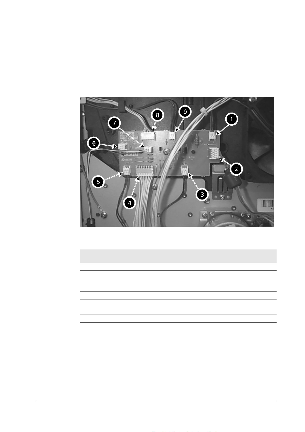
6.1 Board layouts
This section explains the appearance and pin assignment for the printer boards.
The wiring information for these boards is on
Liaison board KP-620
Troubleshooting
Board layouts
6.2 Overall wiring diagram
, page 5.
Table 6. 1 KP-620 connectors
Loc.
above
1 CN8 Fan (large) —
2 CN3 Main motor E1, pin 3 (MOTOR*)/pin 1
3 CN4 Registration clutch —
4 CN1 Engine board KP616/CN14
5 CN5 Feed clutch —
6 CN7 Manual feed clutch —
7 CN9 Cassette detect switch —
8 CN2 Front panel —
9 CN6 Manual feed solenoid —
Connector Connected to: Check points
(+24V)
6-2
FS-6700
Page 3
Troubleshooting
Board layouts
Scanner interface board KP-622
Table 6. 2 CN13 (Scanner CN1) pin assignment
Pin No. Signal
1+5V
2GND
3LONB
4 LASER
5VDOUT+
6VDOUT7PD
8SCCLK
9SCRDY*
10 SCANNER*
11 GND
12 +12V
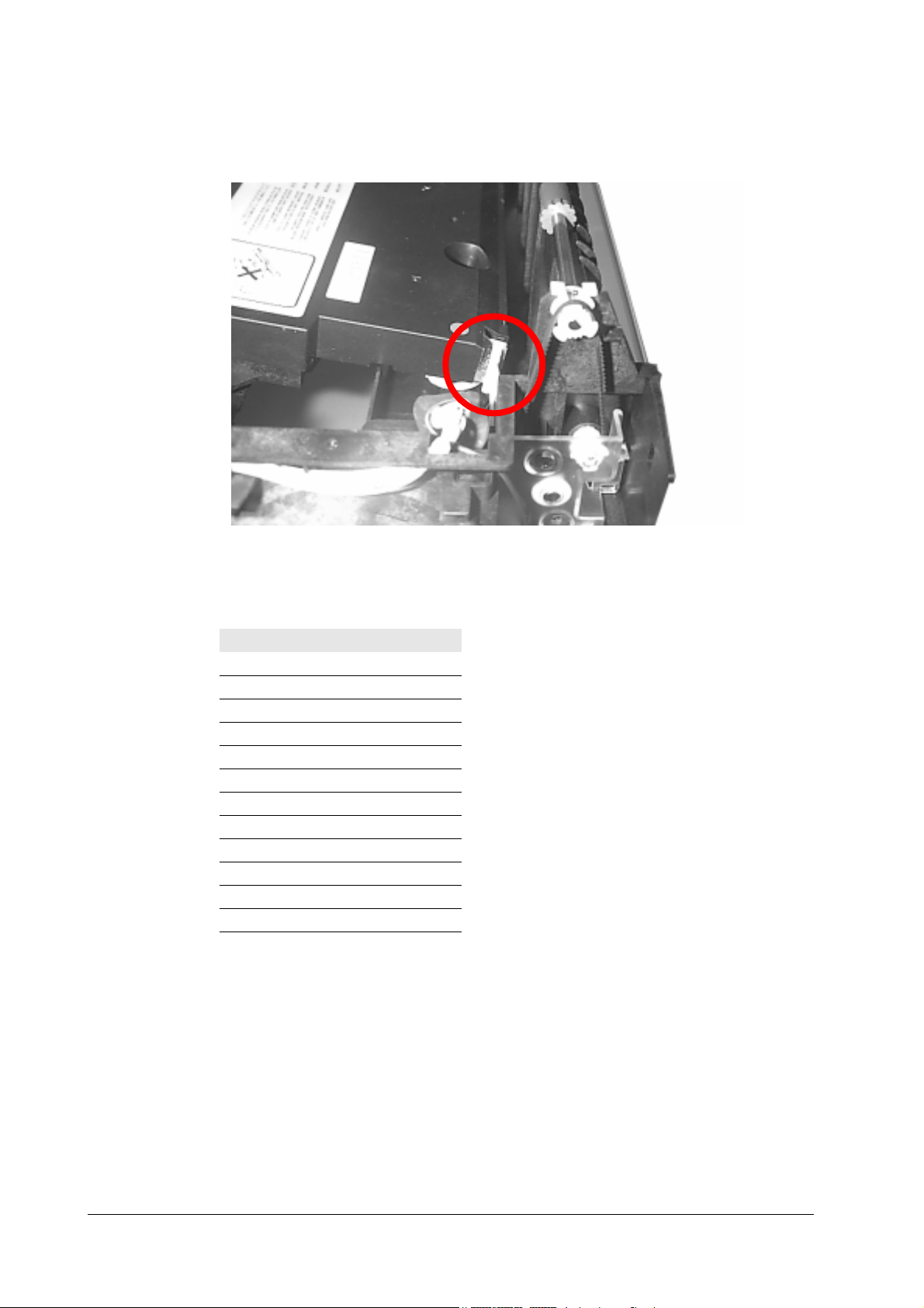
Connect board connector/KP-616
The two connectors at the right side of the printer are mounted on the connect
board. These connectors derive engine signals. For pin assignments, refer to
Overall wiring diagram
, page 5.
6.2
FS-6700
6-3
Page 4
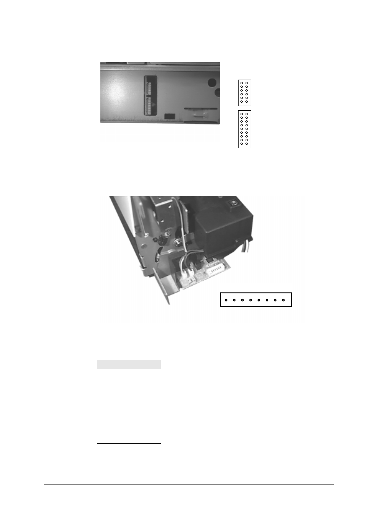
Fuser board KP-505/YC-721
18
Troubleshooting
Board layouts
12
CN13 (for laser scanner unit)
1112
12
CN14 (for KP-620 board)
1718
Table 6. 3 YC-721
Pin No. Signal
1FUPSD*
2+24V
3FDNSD*
4 PFULL*
5 THERM*
6EXITJ*
7GND
8+5V
6-4
FS-6700
Page 5
Troubleshooting
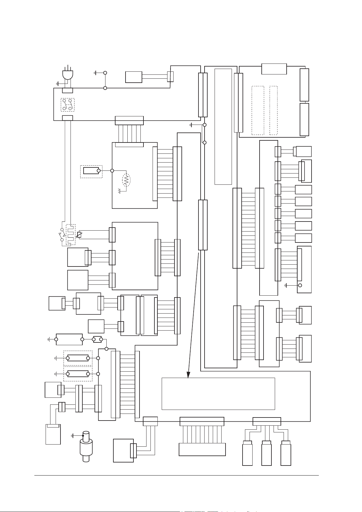
Overall wiring diagram
6.2 Overall wiring diagram
S2029
TONER
SENSOR
MOTOR
S2276
THERMO CUT OUT
SENSOR
TONER
1
2
1
2
S2263
HEATER
SENSOR
SOLENOID
S2021
C
1
1
E
2
2
ZENER PWB
(KP-501)
TRANSFER ROLLER
MAG ROLLER
TONER
2
2
GND
1
1
TDRV*
2
2
+24V
1
1
S2023 S2274
AC IN
(CN1)
POWER SWITCH
(CN2)
FEED UNIT (BASE)
THERMISTER
+5V
THERM*
S2253
PAPER FULL
+5V
1
1
PAPFL*
2
2
GND
3
3
FACE
UP/DOWN
FCUP*
+24V
FDOWN*
TNFULL PWB
(KP-506)
(YC842)
(YC841)
1
2
ERASER
TONER
1
1
GND
2
2
TNRDR*
3
3
+24V
4
4
1
2
1
2
3
1
2
3
S2018
+5V
1
1
TNFULL*
2
2
TSEN*
3
3
ERASER
GND
1
2
HIGH VOLTAGE UNIT
3
4
5
6
7
8
1
1
9
2
2
10
11
12
5
5
(CN2)
13
(CN1)
6
6
14
15
MANUAL PAPER
FEED ROLLER
1
2
1
2
3
1
2
3
1
2
3
4
5
6
7
8
9
10
11
12
13
14
15
BOX FAN
MOTOR
POWER SUPPLY UNIT
(CN5)
+24V COM
+24V COM
+24V COM
(CN2)
(KP-628)
FUSER PWB
(KP-499)
(YC741)
(YC743)
DRUM PWB
(KP-500)
(YC742)
1
2
3
4
5
6
7
8
9
10
11
12
13
14
15
MANUAL FEED
GND
1
1
HAND*
2
2
+5V
3
3
12345
12345
+5V
12345
SENSOR PWB
(CN25)
6
6
+24V
6
(YC723)
(YC724)
(YC722)
1
1
2
2
3
3
1
1
2
2
S2266
+24V
MHVDR*
THVDR1*
CHVON*
THVDR2*
PSEL*
SPVDR1*
SPVDR2*
BIAS*
HVCLK
TONR
TNSCN
+5V
GND
TNRDR*
PAPER SENSOR
+24V COM
BFANDR
1
2
S2011
S2265
SCOVR*
1
PAPER*
2
FEEDS*
3
TNCON*
4
+24V
5
(CN1)
+24V
6
+24V
7
+24V
8
+24V
9
FCOVER*
10
TCOVR*
11
GND
12
S2252
FUPSD*
1
1
+24V
2
2
FDNSD*
(YC721)
3
3
PFULL*
4
4
THERM*
5
5
EXITJ*
6
6
GND
7
7
+5V
8
8
S2007
(YC821)
(YC822)
TSEN*
1
WTONR
2
DRUM RELAY PWB
(KP-505)
ERASE*
3
EECSEL
4
EEDAT
5
EESCLK
6
GND
7
+5V
8
30:SCANR*
60:+5V
(CN27)
123
123
+5V
HANDS*
GND
S2255
(CN6)
1
2
1
1
2
2
3
3
4
4
5
5
6
6
7
7
8
8
9
9
10
10
11
11
12
12
1
1
2
2
3
3
4
4
5
5
6
6
7
7
8
8
1
1
2
2
3
3
4
4
5
5
6
6
7
7
8
8
27:CASET0
28:GND
29:CASET1
57:+24V
58:HEAT*
59:BOXFAN*
(CN4)
GND
1
1
GND
2
2
GND
3
3
VCC
4
4
(CN15)
VCC
5
5
VCC
6
6
ZCROS
7
7
PHET
8
HEAT*
8
9
9
10
10
BOXFAN*
S2277
G2G1
ENGINE PWB (KP-614)
(CN12)
(CN21)
(CN23)
(CN24)
17:RDY*
18:PDIN*
19:VSYNC*
20:GND
21:PRINT*
22:SCNCLK
23:PDOUT*
24:GND
25:RESET*
26:SCRDY*
47:REGDR*
48:+5V
49:+24V
50:MOTOR*
51:RCOVR*
52:+5V
53:+24V
54:ZCROS
55:PHET
56:+5V
(CN27)
6
5
4
3
2
1
1
GND
10
5
4
3
2
OPSL1
OPSL2
OPSDI
OPSDO
6
7
8
9
TO OPTION UNIT
6
OPSL0
5
+5V
OPRDY*
A1 :GND
A2 :VCC
A3 :VCC
A4 :EGIR*
A5 :VSREQ*
A6 :CBSY*
A7 :SC
A8 :RDY*
A9 :NC
A10:NC
A11:FPDATA
A12:PRINT*
A13:RESET*
A14:OUTPE*
A15:GND
A16:GND
B1 :GND
B2 :VCC
B3 :VCC
B4 :NC
B5 :SBSY*
B6 :SCLK
B7 :CPRDY
B8 :CINH*
B9 :VCC
B10:NC
B11:VSYNC*
B12:PDOUT*
B13:FPCLK
B14:VDATA
B15:FPDIR
B16:GND
(CN12)
1
2
CONNECT PWB (KP-616)
3
4
5
6
7
(CN14)
8
9
10
11
12
13
14
15
16
17
18
72pin DIMM 1-SLOT (YS1)
(YC6)
S2258
GND
1
BFPCLK
2
BFPDIR
3
BFPDATA
4
+5V
5
FANDR*
6
FEDDR*
7
MPFSOL*
8
MPFCLH*
9
MTRCLK
10
REGDR*
11
MOTOR*
12
RCOVR*
13
+24V
14
+24V
15
+24V
16
GND
17
GND
18
S2261
+5V (LD)
1
1
GND
2
2
LONB*
3
3
LASER*
4
4
VIDEO+
5
5
(CN13)
VIDEO-
6
6
PDIN*
7
7
SCCLK
8
8
SCRDY*
9
9
SCANR*
10
10
GND
11
11
+24V
12
12
6 :LASER*
7 :SCLOCK
8 :GND
9 :CBSY*
10:VDOUT+
11:CPREDY
12:GND
13:SC
14:VDOUT-
15:CINH*
16:GND
36:+5V
37:+24V
38:FANDR*
39:FEDDR*
40:+5V
41:+24V
42:MPFSOL*
43:MPFCLH*
44:+5V
45:+24V
46:MTRCLK
10
9 8 7
10
9 8 7
+24V
OPSCK*
S2256
1
2 3 4
GND
CAS5
1
2
PAPER SIZE
LENGTH SW3
PC-Card
(YC3)
OPTION I/F CONNECTOR (YC1,2)
72pin PC-SIMM 2-SLOTS (YS3)
RELAY PWB (KP-620)
1
1
2
2
3
3
4
4
5
5
6
6
7
7
8
8
9
9
(CN1)
10
10
11
11
12
12
13
13
14
14
15
15
16
16
17
17
18
18
1
1
APC PWB (KP-622)
2
2
3
3
4
4
(CN1)
5
5
6
6
7
7
8
8
9
9
10
10
11
11
12
12
1 :EGIR*
2 :LONB*
3 :SBSY*
4 :GND
5 :VSREQ*
31:VDATA
32:GND
33:OUTPE*
34:CASET2
35:PPRDY
(CN28)
6
6
GND
CAS4
1
2
PAPER SIZE
LENGTH SW2
(KP-613)
S2279
(CN9)
+5V
121
CASS
2
S2259
+24V
1
1
(CN3) (CN4) (CN5) (CN6) (CN7) (CN8)
GND
2
2
MOTOR*
3
3
MMTCLK
4
4
+24V
1
1
REGDR*
2
2
+24V
1
1
FEDDR*
2
2
+24V
1
1
MPFSOL*
2
2
+24V
1
1
MPFCL*
2
2
FANCOM
121
FANDR*
2
S2260
+5V
1
1
FPDAT
2
2
+5V
(CN2)
3
3
FPDIR
4
4
GND
5
5
FPCLK
6
6
GNG
7
7
S02025
S2272
+5V
1
1
(CN3)
PDIN*
2
2
GND
3
3
S2273
SCCLK
1
1
SCRDY*
(CN2)
2
2
SCANR*
3
3
GND
4
4
+24V
5
5
12345
12345
CAS3
2
LENGTH SW1
Main Controller
1
2
S2257
GND
1
PAPER SIZE
PARALLEL I/F CONN.
(YC4) (YC5)
SERIAL I/F CONN.
CASSETTE
SWITCH
Main Motor
1
1
2
2
3
3
4
4
REGIST
CLUTCH
FEED
CLUTCH
M.FEED
SOLENOID
M.FEED
CLUTCH
FAN
MOTOR
1
2
Front Panel
(KP-503)
3
4
5
6
7
PD PWB
(KP-637)
1
1
2
2
3
3
Polygon Motor
1
1
2
2
3
3
4
4
5
5
FS-6700
6-5
Page 6

6.3 Diagnostic
The printer automatically executes its self-diagnostic test when it is powered up
(displaying
below.
When the printer locates the error with a specific item, it calls for operator*s atten-
tion by showing the appropriate message on the operator panel display.
The diagnostic test is done on the following systems simultaneously:
Engine system (E errors)
•
Controller system (F errors)
•
Flowcharts on the following pages show the order and the items diagnosed in each
system.
Note Diagnostic test is cancelled if one of the user-accessible covers
Self-test
is opened during the test.
Troubleshooting
Diagnostic
). The sequence and the items to be diagnosed are explained
6-6
FS-6700
Page 7
Troubleshooting
Diagnostic
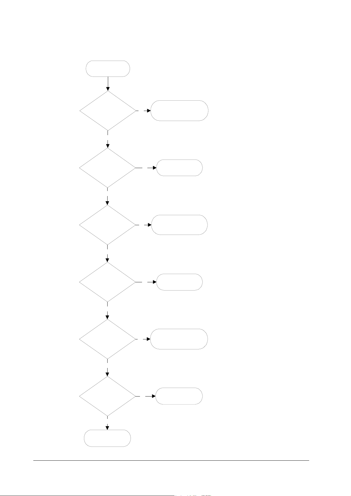
Engine diagnostics flow
1
Power on
2
Engine ROM cheksum
OK?
Yes
3
Fuser thermistor OK?
The heater lamp is turned on.
Yes
The scanner polygon motor revolves.
4
Polygon motor OK?
The polygon motor stops revolving.
Yes
The main motor revolves.
The eraser array turns on.
No
No
E6 - Engine ROM error
No
9
10
E4 - Fuser error
11
E2 - Polygon motor
error
5
Eraser array OK?
Yes
The eraser array turns off.
6
Main motor OK?
Yes
7
Heater temperature
OK?
The main motor turns off.
Yes
8
Engine is ready.
No
No
No
12
E5 - Eraser error
13
E1 - Main motor error
14
E4 - Heater error
FS-6700
6-7
Page 8
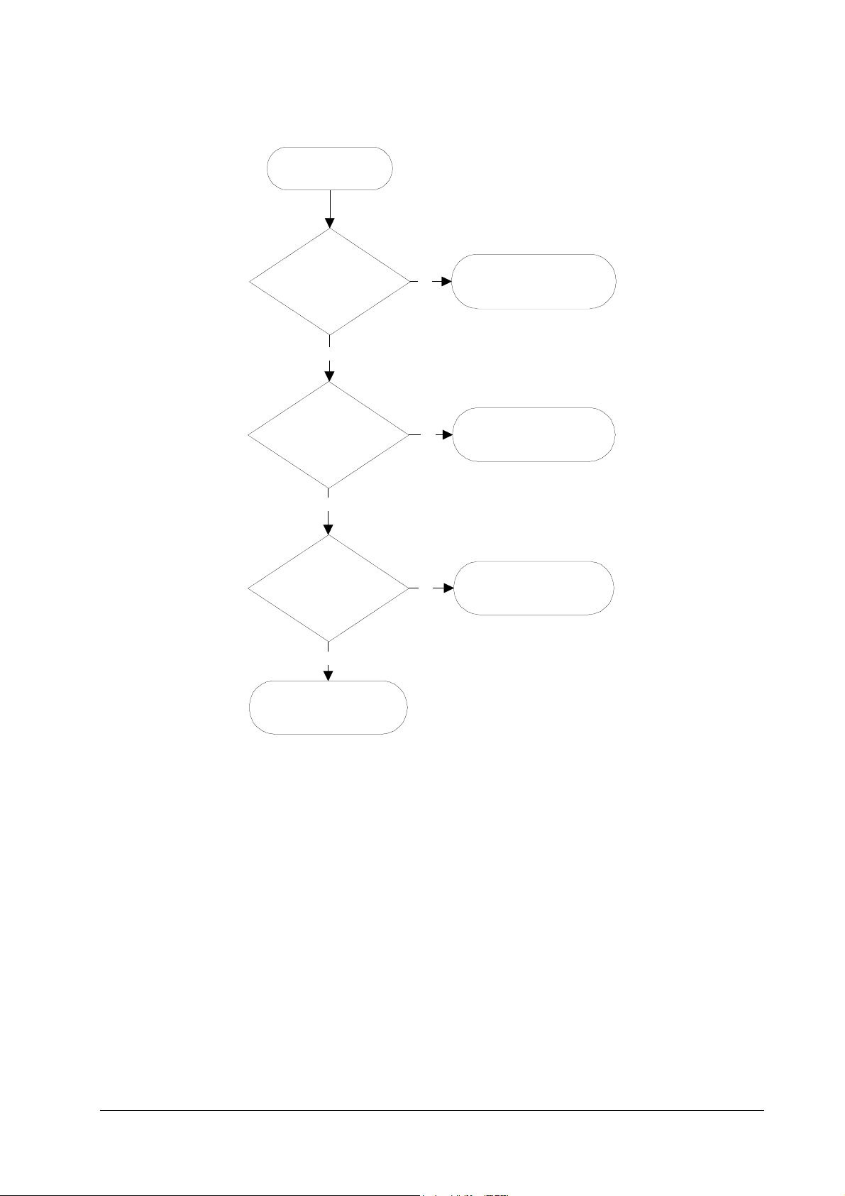
Logic controller diagnostics flow
1
Power on
Troubleshooting
Diagnostic
2
System ROM cheksum
OK?
Yes
3
Communication
established between
engine and main
CPUs?
Yes
4
System memory OK?
Yes
No
No
No
6
F1 - System ROM error
7
E0 - Communication
error
8
F2 - System memory
error
5
Controller is ready.
For details on how to react to the results of diagnostics, refer to section Service
errors on page 6-19.
6-8
FS-6700
Page 9

Troubleshooting
General error handling
6.4 General error handling
Priority
Each error message has a priority over the others. Thus, if two or more error messages are given simultaneously, the error message having the highest priority is
shown. The priority is as follows (from the highest to the lowest):
Table 6. 4 Message priority
Error message Category Remarks
Call service person F0 Service error Refer to
I/F occupied —
Top cover open User-recoverable error If not recovered, refer to
Paper feed unit open User-recoverable error If not recovered, refer to
Side cover open User-recoverable error Refer to
Opt. Feeder 1 (2) rear
cover open
Duplex unit rear cover
open
Replace Toner/Clean
printerb
Missing Waste-toner
bottle
Replace Waste-toner
bottle
Clean printer/Press
CONTINUE
Paper jamb User-recoverable error
Face-down tray paper
fill
MEMORY CARD err Insert
again
Insert the same
MEMORY CARD
Print Cancel? —
Memory overflow ...
Press CONTINUE
Print overrun ...
Press CONTINUE
KPDL error ... Press
CONTINUE
MEMORYCARD err ...
Press CONTINUE
Opt. ROM error ...
Press CONTINUE
Set paper/Press
CONTINUE
Load paper User-recoverable error
Add paper User-recoverable error
User-recoverable error with PF-25 feeder
User-recoverable error with DU-25 duplexer
User-recoverable error
User-recoverable error If not recovered, refer to
User-recoverable error
User-recoverable error
User-recoverable error
User-recoverable error
User-recoverable error
User-recoverable error
User-recoverable error
User-recoverable error
User-recoverable error
User-recoverable error
User-recoverable error
FS-6700
6-9
Page 10

Table 6. 4 Message priority
Error message Category Remarks
Self test —
Sleeping —
Please wait —
PJL OPMSG/STMSG —
Processing —
Waiting —
FormFeed TimeOut —
Option interface Error User-recoverable error
Toner low TK-20/Clean
printer
Warning/Low memory -
Battery error/MEMORY
CARD
Format error/MEMORY
CARD
Warning battery/
MEMORY CARD
Ready —
Troubleshooting
General error handling
User-recoverable error
User-recoverable error
User-recoverable error
User-recoverable error
6-10
FS-6700
Page 11
Troubleshooting
User-recoverable errors
6.5 User-recoverable errors
User-recoverable errors do not normally require a service call unless the suggested
remedy does not solve them. The instructions below indicate how to respond to
problems indicated by the operator panel symbolic indicators and by the panel display.
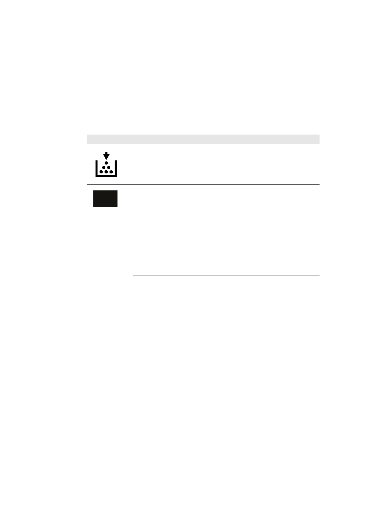
Table 6. 5 User-recoverable errors
Indication Corrective action
Flashing
Lit
The printer has run low on toner. The toner should
be replaced as soon as possible.
Install a new toner kit. See chapter 1.
Fast flashing
Slow flashing
Lit
ATTENTION
Side cover Open Open the side cover, then close tightly.
Paper feed unit Open Open the paper feed unit, then close tightly.
Face-down tray paper full The face-down tray has become full (approx. 250
Add paper Add paper to the paper cassette or multi-purpose
Set paper/Press CONTINUECONT
Load paper papersize The paper size does not match. The size of the paper
Paper jam Open the top cover or the paper feed unit and correct
Flashing
Lit
There is a paper jam. There is a possibility that
paper may be jammed at the point indicated by
flashing, open and remove any jammed paper. See
Section
The paper has run out in the paper cassette or
multi-purpose tray. Please insert paper. See Section
This indicates either the current paper feeder or the
paper output point.
The printer has insufficient memory available or the
printer is warming up (Pleasewait). Confirm the
message indicated on the message display. See Section
Note the maintenance message on the message display and consult Table
pages). Remove all printed pages from the face-down
tray. When the printer senses that the face-down
tray is empty again, it will continues printing into
the face-down tray. (Model FS-3700/+ only)
tray.
Add a sheet of paper to the multi-purpose tray (man-
ual mode), and press the CONTINUECONT key.
in the cassette is different to the size specified by the
application software or by PRESCRIBE II. Either
put paper of the specified size into the cassette. See
Section 1.4.If the CONTINUECONT key is pressed,
printing will be resumed. However, if more than one
sheet is to be printed, the same message will again
be displayed from the second sheet onward. It is also
possible to abandon printing by pressing the CANCEL key.
the paper jam (or paper mis-feeding in the cassette).
See Section
FS-6700
6-11
Page 12

Table 6. 5 User-recoverable errors
Indication Corrective action
Warning low memory The printer’s internal memory is running low due to
Toner low TK-20/Clean
printer
Replace Toner/Clean printer Replace the toner container using a new toner kit.
Clean printer..Press CONTINUECONT
ReplaceWaste- toner bottle Replace the old waste toner bottle with the new one
Missing Waste-toner bottle Install the waste toner bottle. See Section ... The
Memory overflow..Press CONTINUECONT
Print overrun..Press CONTINUECONT
MEMORY CARD err/Insertagain The memory card is accidentally removed from the
Insert the same MEMORY CARD You have inserted the wrong memory card when the
Troubleshooting
User-recoverable errors
the number of fonts and macros downloaded. Print a
status page to see how much user memory is left,
and try deleting unnecessary fonts and macros. See
the PRESCRIBE II DELF and DELM commands
explanation in the programming manual (CD-ROM).
Replace the toner container using a new toner kit.
See Section
The printer does not operate when this message is
displayed. See section
Please clean the inside of the printer. See Section
...This message will be displayed when replacing the
toner container after the message ReplaceTonerCleanprinter has been displayed. After cleaning the
inside of the printer, press the CONTINUECONT
key and the printer will be ready for printing.
which is included in the TK-20/TK-20HTK-20G
toner kit. The message will also be shown if the
waste toner bottle has become full. The waste toner
bottle should be replaced when the message display
eventually shows TonerlowTK-20Cleanprinter. See
Section
printer does not operate when this message is displayed.
The total amount of data received by the printer
exceeds the printer’s internal memory. Try adding
more memory (expansion RAM). Press the CONTINUECONT key to resume printing. You can abandon
printing by the CANCEL key.
The data transferred to the printer was too complex
to print on a page. Press the CONTINUECONT key
to resume printing. (The page may break in some
pages.)You can abandon printing by the CANCEL
key.Note: After this message has been displayed,
Page protect mode will be On. To maintain optimum
use of memory during printing, display >Pageprotect from the control panel, and re-select Auto.See
the printerís userís manual.
printer’s memory card slot during reading. If you
continue reading the memory card, insert the same
memory card into the slot again. The printer again
reads it from the beginning of the data.Note: We recommend that you follow the reading procedure from
the beginning to ensure correct reading of the memory card.
Insertagain message was displayed. Remove the
wrong memory card from the printer’s memory card
slot and insert the correct memory card. The printer
again reads it from the beginning of the data.
6-12
FS-6700
Page 13

Troubleshooting
User-recoverable errors
Table 6. 5 User-recoverable errors
Format error MEMORY CARD This message appears when the printer is in the
Warning battery MEMORY CARD This message appears when the printer is in the
MEMORY CARD err/ ##..Press
CONTINUECONT
>Read fonts Failed The amount of memory available for the fonts
I/F occupied This message is displayed when you attempt to use
Processing PAR FIT A4 FIT (image FITting) flashes to indicate that a loss of
Processing PAR 600 A4ÍProcessing
PAR 300 A4
>Read fonts Failed The amount of memory available for the fonts
Indication Corrective action
ready state and the memory card is not formatted,
and therefore cannot be read or written. Follow the
procedure on Section ... to format the card.
ready state and the battery in the memory card is
low. You can still enter the memory card mode, but
the battery should be changed as soon as possible.
This message appears when an error occurs during
access to the memory card using the PRESCRIBE II
ICCD command or from the printer’s control panel
(codes 09 and 11 only). The error is indicated by one
of the numbers ## listed under the Memory card
errors which follows.
header parts of font is too small to load more fonts.
Try deleting unnecessary fonts and macros.
the printer’s control panel to change the environmental settings on the interface from which data are
presently being received.
raster data occurred when the data was compressed
to be fitted within the currently available memory.
Flashing FIT extinguishes automatically when the
job times out; the printer receives the next data from
the host computer; or if you press any key on the
printer’s control panel. Try adding more memory in
the printer to prevent this error.
Change of the resolution indicator from 600 to 300
(flashing) means that the job in 600-dpi resolution
was not able to run within the currently available
memory. The resolution reverts to 600 dpi automatically when the job times out; the printer receives the
next data from the host computer; or if you press
any key on the printer’s control panel. Try adding
more memory in the printer to prevent this error.
header parts of font is too small to load more fonts.
Try deleting unnecessary fonts and macros.
FS-6700
Memory card errors
Table 6. 6 Memory card errors
Error
code
01 SRAM Card size error (An attempt was made to write data of greater
02 SRAM No memory card inserted. Insert a proper memory card.
Applicable
card type
Meaning
than 16 MB in size.). Reduce the size of the data to be written
from the host computer to 16 MB or less; or, a file name could
not be found in the memory card.
6-13
Page 14

Table 6. 6 Memory card errors
Troubleshooting
User-recoverable errors
Error
code
03 SRAM/flush Non PCMCIA card. Replace the card with a PCMCIA card.
04 SRAM Not RAM card. Use a SRAM-type card if you want to write data
05 SRAM Memory card battery error. Replace the memory card’s internal
06 SRAM Memory card protect error. Release the write protection on the
07 SRAM Non-Kyocera format. Reformat the memory card using MODE
08 SRAM Partition name error. Follow instructions given attempt in
09 SRAM Memory card data full error (An attempt was made to write
10 - Reserved
11 SRAM Data name full (An attempt was made to write more than 127
12 - Reserved
13 Flush Erase logic error with flash memory card. Try replacing the
14 - Reserved
15 Flash Non PCMCIA flush card. Replace the card with a PCMCIA
16 - Reserved
17 Flush Unable to write to the flash memory card due to insufficient
18 Flush Writing error. Try replacing the memory card.
19 - Reserved
Applicable
card type
Meaning
to an memory card.
battery with a new one.
memory card when you write data to the memory card.
SELECT (See the printerís userís manual).
Chapter 2 to properly name the destination.
data exceeding the capacity of the memory card). Abandon the
writing operation on the host computer first. Press CONTINUE
key; when the message turns to Waiting, press FORM FEED
key (Ready).
destination data names). Press CONTINUE key (Ready).
memory card.
flush card.
printer memory. Either delete unnecessary macros or fonts
stored in the printer, or extend the printer’s available memory.
For details on memory card availability, see section Printer specifications in chap-
ter 1.
6-14
FS-6700
Page 15

Troubleshooting
Service errors
6.6 Service errors
Table 6. 7 Service person errors
The printer does not operate when a message beginning with E, F, or C is displayed. The total numer of pages printed is also indicated. The message is categorized as follows:
Message Corrective action
Call service person
En:123456
Call service person
Fn:123456
Call service person Cn:
123456
Call service person Dn:
123456
Mechanical error (n=0, 1, 2, ...). Follow the appropriate
instructions provided in this section.
Controller error (n=0, 1, 2, ...). Follow the appropriate
instructions provided in this section.
Option equipment error (n=0, 1, 2, Ö). This message pertains to either the sorter or duplexer. C1 through C3 are
relevant to the duplexer; C4 through C6 to the sorter.
See the service manual appropriate to the option used
with the printer.
Engine firmware download error (n=0, 1, 2, Ö). See section Updating the engine firmware in chapter 3.
FS-6700
6-15
Page 16

E0—Communication error
Table 6. 8 E0 error
Communication between the
engine controller and the
main controller is failed.
E1—Main motor error
Table 6. 9 E1 error
The main motor is over-
torqued.
Troubleshooting
Service errors
Meaning Suggested causes Corrective action
• Controller gate array
defect
• Connector failure between
the engine and the main
controller
• Overrun in the engine
system, deactivating the
progam flash ROM
Meaning Suggested causes Corrective action
• Overcurrent in the main
motor circuitry due to an
axcessive torque
• Loose connector to motor
• Defective gate array on
the engine board
• No response from the
main motor due to the
defective motor driver
(transistor)
• Defective overcurrent
detector (transistor)
Verify connector connections.
Replace the engine board
and/or the main controller
board.
Follow the flow chart on page
17, Figure 6.1 and the following.
6-16
FS-6700
Page 17

Troubleshooting
Service errors
Figure 6.1 E1 error
E1
(Main motor error)
Connect tester to #3
of CN1 of motor.
Turn printer power
off, then on agai.
Print a status page.
Is #3(MOTOR*) of
CN1 of motor L?
Yes
Is #1 of CN1 of motor
+24V?
Yes
Turn printer power
off, then on again.
Print a status page
No
No
Connect tester to #3
of CN3 of KP-620.
1
Turn printer power
off, then on again.
Print a status page.
Is #3 (MOTOR*)
of CN3 of KP-620
L?
Yes
Replace harness
S02259 bet. motor
and KP-620.
No
3
FS-6700
Does motor clock appear
at #4 of CN1 of motor?
Yes
2
No
Replace driver unit.
6-17
Page 18

Figure 6.2 E1 error—Continued
1
Connect tester to #4
of CN3 of KP-620.
Turn printer power
off, then on again.
Print a status page.
Troubleshooting
Service errors
Does motor clock
appear at #4 of CN3
of motor?
Yes
Turn printer power
off, the on again.
Print a status page.
Does motor clock appear
at #10 of CN1 of KP-620?
Yes
Turn printer power
off, then on again.
Print a status page.
Does motor clock appear
at #10 of CN14 of
KP-616?
No
Replace harness bet.
motor and KP-620
(S02259).
No
Replace KP-620
board.
No
Yes
Connect tester bet.
#10 of CN14 of
KP-616 and #46 of
CN21 of KP-614.
Conducted?
Yes
Replace KP-614.
No
6-18
Replace harness bet.
KP-620 and KP-616.
Replace KP-616
board.
FS-6700
Page 19

Troubleshooting
Service errors
Figure 6.3 E1 error—Continued
2
Connect tester to #1 of
CN3 of KP-620.
Is #1 of CN3 of KP-620
+24V?
Yes
Replace harness bet.
main and KP-620.
No
Is volt. bet. #14 and #16 of
CN1 of KP-620 +24V?
Yes
Replace KP-620.
No
Connect tester bet. #14
and #16 of CN14 of
KP-616.
Is volt. bet. #14 and #16 of
CN14 of KP-616 +24V?
No
Yes
Replace harness bet.
KP-620 and KP-616.
Is volt. bet. #5 and #9 of
CN22 of KP-614 +24V?
Yes
Connect tester bet.
#14-16 of CN 14 of
KP-616 and either pin of
37, 41, 45, 49, 53, and
57 of CN21 of KP-614.
Conducted?
Yes
Replace KP-614.
No
Replace KP-628.
No
Replace KP-616.
FS-6700
6-19
Page 20

Figure 6.4 E1 error—End
3
Turn printer power off,
then on again. Print a
status page.
Troubleshooting
Service errors
Is #12 of CN1 of KP-620
?
Yes
Replace KP-620.
No
Turn printer power off,
then on again. Print a
status page.
Is #12 of CN14 of KP-616
?
Yes
Replace harness bet.
KP-620 and KP-616.
No
Connect tester #12 of
CN14 of KP-616 and
#50 of CN21 of KP-614.
Conducted?
No
6-20
Yes
Replace KP-616.Replace KP-614.
FS-6700
Page 21

Troubleshooting
Service errors
Table 6. 10 E2 error
E2—Laser scanner motor error
Meaning Suggested causes Corrective action
The polygon motor does not
deliver a synchronous output
(L) within the predetermined
period of time.
• Timeout in the predetermined period of lead time
which the scanner motor
speed has to be reached at
start up (SCRDY*)
• Connector insertion error
• Defective gate array on
the engine board
• Time out dur to the defective scanner motor driver
(transistor)
Follow the flow chart on the
next page.
FS-6700
6-21
Page 22

Figure 6.5 E2 error
E2
(Scanner motor
error)
Connect tester to #10
of CN1 of KP-622.
Troubleshooting
Service errors
Is #10 (SCANR*)
of CN1 of
KP-622 L?
Yes
Turn printer power
off, then on again.
Print a status page.
Does clock
appear at #8 of
CN1 of KP-622?
Yes
Connect tester to #10
No
No
of CN13 of KP-616.
Turn printer
power off, then
on again. Print a
status page.
Turn printer power
off, then on again.
Is #10 of
CN13 of
KP-616 ?
Yes
No
3
1
Does clock
appear at #8 of
CN13 of KP-616?
Yes
Replace harness bet.
KP-616 and scanner
unit.
6-22
No
2
FS-6700
Page 23

Troubleshooting
Service errors
Figure 6.6 E2 error—Continued
1
Is #12 of CN1 of
KP-622 +24V?
Yes
Turn printer power off,
then on again. Print a
status page.
Is #9 of CN1 of
KP-622 low?
Yes
Turn printer power off,
then on again. Print a
status page.
Is #9 of CN13 of
KP-616 low?
No
No
No
Replace laser
scanner unit.
Are #14-16 of CN14
of KP-616 +24V?
Yes
No
Are #14-16 of CN14
of KP-616 +24V?
Yes
Connect tester bet.
#14-16 of CN14 of KP-616
and either of 37, 41, 45,
49, 53, and 57 of KP-614.
No
Repplace KP-628.
Yes
Connect tester to #9
of CN13 of KP-616
and #26 of CN21 of
KP-614.
Conducted?
Yes
Replace KP-614.
Replace harness bet.
KP-616 and laser
No
scanner unit.
Replace KP-616.
Conducted?
Yes
No
FS-6700
6-23
Page 24

Figure 6.7 E2 error—End
Troubleshooting
Service errors
2
Connect tester bet. #8
of CN13 of KP-616 and
#22 of CN21 of
KP-614.
Conducted?
Yes
No
3
Connect tester bet.
#10 of CN13 of KP-616
and #30 of CN21 of
KP-614.
Conducted?
Yes
No
Replace KP-614.
Replace KP-616.
6-24
FS-6700
Page 25

Troubleshooting
Service errors
Table 6. 11
E3 - Laser beam detection error
Meaning Suggested causes Corrective action
Beam detection is failed. The
photo detector board does not
deliver a synchronous output
(L).
• No beam hit due to the
laser diode defect (PD*)
• Improper connector insertion
• Soiled/defective beam
detector (pin-photo diode)
sensor
• Defective safety lock
• Unoperative gate array
input port
Follow the flow chart on the
next page.
FS-6700
6-25
Page 26

Figure 6.8 E3 error
E3
(Scanner beam
detector error)
Connect tester to #4 of
CN1 of KP-622.
Turn printer power
off, then on again.
Troubleshooting
Service errors
Is #4 (LASER) of CN1
of KP-622 low?
Yes
Turn printer power
off, then on again.
Does low-level pulse
appear at #7 (PD) of CN1
of KP-622?
Yes
Turn printer power
off, then on again.
Print a status page.
No
No
Connect tester to
#4 of CN13 of
KP-616.
Replace laser
scanner unit.
Turn printer power
off, then on again.
Is #4 of CN13 of KP-616
low?
Yes
No
2
Yes
Does low-level pulse
appear at #7 of CN13 of
KP-616?
Yes
No
Replace harness bet.
KP-616 and laser
scanner unit.
6-26
FS-6700
Page 27

Troubleshooting
Service errors
Figure 6.9 E3 error—Continued
1
Connect tester #7 of
CN13 of KP-616
and #18 of CN21 of
KP-614.
Conducted?
Yes
No
2
Connect tester to #4
of CN13 of KP-616
and #6 of CN21 of
KP-614.
Conducted?
Yes
No
Replace KP-614.
Replace KP-616.
FS-6700
6-27
Page 28

E4 - Fuser heater error
Table 6. 12 E4 error
The fuser heater is not intact
due to disconnection or the
circuit failure.
Troubleshooting
Service errors
Meaning Suggested causes Corrective action
• Blown-out thermistor
• Improper connector inser-
tion
• Blown-out halogen heater
• Blown-out thermostat
• Comparator defect on the
engine board
• Defective engine CPU
(input port)
• Defective gate array
(input/output port operation)
Follow the flow chart on the
next page.
6-28
FS-6700
Page 29

Troubleshooting
Service errors
Figure 6.10 E4 error
(Fuser heater error)
immediately after
E4
"E4" shown
No
power up?
Yes
Turn printer power off
and remove power
cable.
Measure DC resistance
between #5 and #8 of
YC721 on KP-499
(fuser) board.
Less than 1MΩ?
Yes
No
Replace fuser
unit.
Replace
fuser unit.
Measure fuser
roller
temperature.
180-220°C?
Yes
End
No
Replace KP-614 board. If
not solved, replace power
supply.
FS-6700
Replace KP-614 board. If not
solved, replace harness between
KP-499 and KP-614 boards.
6-29
Page 30

E5—Eraser error
Table 6. 13 E5 error
The eraser is blown out or the
power supply does not reach
to the eraser.
Figure 6.11 E5 error
Troubleshooting
Service errors
Meaning Suggested causes Corrective action
• Blown-out LED chip(s)
• Connector insertion error
• Defective gate array
(input/output port)
E5
[Eraser error]
Take the drum
unit out.
Follow the flow chart on the
next page.
Measure resistance
between #1 and #3
of YC741 on KP-500.
Infinity?
Yes
Replaceeraser (drum unit).
If not recovered, replace
KP-500.
No
Replace harness between
KP-614 and KP-505. If not
recovered, replace KP-505.
6-30
FS-6700
Page 31

Troubleshooting
Service errors
Table 6. 14 ED error
Table 6. 15 E9 error
ED—Flash ROM error
Meaning Suggested causes Corrective action
Checksum is erroneous with
the flash ROM.
E9 - Toner motor error
Meaning Suggested causes Corrective action
The toner motor is overtorqued.
• Data readout error on the
flash ROM
• Overcurrent in the toner
motor circuitry due to an
axcessive torque
•Loose connector
• Defective gate array on
the engine board
• Defective toner motor
overcurrent detector
Replace the engine board.
Follow the flow chart on the
next page.
Figure 6.12 E9 error
E9
(Toner motor
error)
Replace with a
new developer
unit.
E9 goes
off?
Yes
END
No
Replace KP-614
board.
FS-6700
6-31
Page 32

F0 - Front control panel error
Table 6. 16 F0 error
Communication is failed
between the front panel and
the main controller.
F1 - System ROM error
Table 6. 17 F1 error
Checksum is failed with
EPROMs on the main controller board.
F2 - Main memory error
Table 6. 18 F2 error
Troubleshooting
Service errors
Meaning Suggested causes Corrective action
• — Replace the main controller
board. To remove the main
controller board, see page 2-9.
Meaning Suggested causes Corrective action
• - Replace the main controller
board. To remove the main
controller board, see page 2-9.
Checksum is failed with the
RAM on the main controller
board.
F3 - General failure
Table 6. 19 F3 error
Miscellaneous failure with
the main controller, other
than F0, F1, and F3, above.
False error—Feed unit cover open
Meaning Suggested causes Corrective action
• - Replace the main controller
board. To remove the main
controller board, see page 2-9.
Meaning Suggested causes Corrective action
• - Turn printer power off, then
on again. If not solved,
replace the main controller
board. To remove the main
controller board, see page 2-9.
6-32
FS-6700
Page 33

Troubleshooting
Service errors
Figure 6.13 False error—Feed unit cover open
False error
[Feed unit cover
open]
Connect tester to #10 of
CN1 on KP-628.
Is #10
(FCOVER) low?
Yes
Connect tester to #10
of CN22 on KP-614.
Is #10 low?
Yes
Replace KP-614.
No
Replace KP-614
board.
No
Replace KP-628.
FS-6700
6-33
Page 34
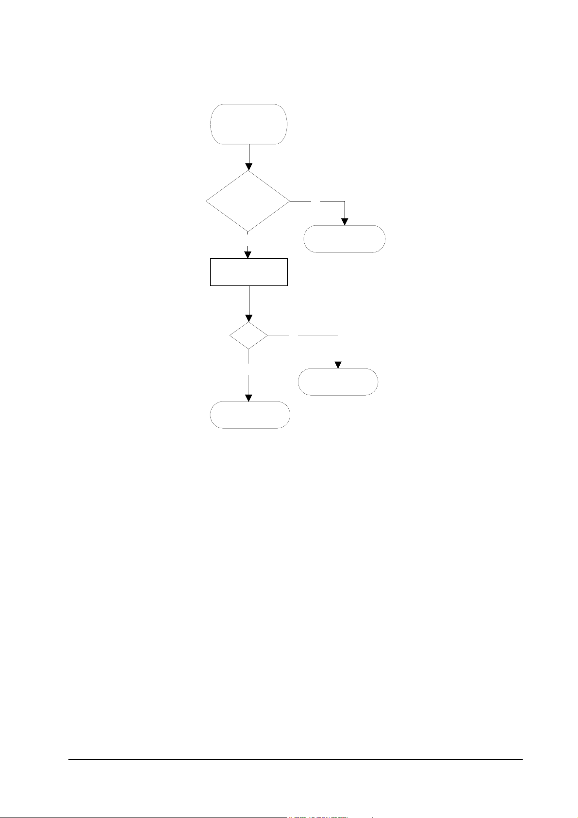
Figure 6.14 Falser error—Top cover open
False error
[Top cover
open]
Is #11 (TCOVER)
of CN1 on KP-628
low?
Troubleshooting
Service errors
No
Yes
Connect tester to #11
of CN22 on KP-614.
Is #11
low?
Yes
Replace KP-614.
Replace KP-628
board.
No
Replace KP-628.
6-34
FS-6700
Page 35

Troubleshooting
Service errors
Figure 6.15 False error—Side cover open
False error
[Side cover
open]
Is #1 (SCOVER)
of CN1 on KP-628
low?
No
Yes
Connect tester to #1 of
CN22 on KP-614.
Is #1 low?
Yes
Replace KP-614.
Replace KP-628
board.
No
Replace KP-628.
FS-6700
6-35
Page 36

Figure 6.16 False error—Missing waste toner bottle
False error
[Missing waste
toner bottle]
Is #4 (TNCON*)
of CN1 on KP-628
low?
Troubleshooting
Service errors
No
Yes
Connect tester to #4 of
CN22 on KP-614.
Is #4 low?
Yes
Replace KP-614.
Replace KP-628
board.
No
Replace KP-628.
6-36
FS-6700
Page 37

Troubleshooting
Print quality problems
6.7 Print quality problems
Print quality problems range from uneven tone to completely blank output. The
troubleshooting procedure for each type of problem is given below.
Completely blank printout
Checkpoint Suggested remedy
Check the developer unit. • Check that the developer unit is inserted correctly
All-black printout
Check point Suggested remedy
Check the main charger unit
installation.
• Check that the developer ’s connector is connected properly.
• Open the printer side cover and check that the main
charger unit is correctly seated. To do this, take out the
main charger unit from the printer; then reinstall it carefully.
Dropouts, horizontal streak, black dots
Check point Suggested remedy
Clean the main charger. • Open the side (drum access) cover. Pull out the green
knob on the main charger. Pull and push in several
Note the spacing of the
defects. Use the Repetitive
defect gauge on page6-43.
times. For details, see page 5,
printer
• If the defects occur at regular intervals of 60.6 mm, the
problem may be a dirty transfer roller. Clean or replace
the tranfer roller.
• If the defects occur at regular intervals of 125.6 mm, the
problem may be a damaged drum unit or fuser roller.
Replace the drum unit or fuser unit accordingly.
• If the defects occur at regular intervals of 39.3 mm, the
problem may be a damaged developing roller. Replace
the developer unit, if necessary (page 9,
developer unit
.
).
3.3. Cleaning the
Removing the
FS-6700
6-37
Page 38

Black vertical streaks
Check point Suggested remedy
Check the front display for
indication of “Toner low.”
Contaminated main charger
wire.
Unsharp printing
Troubleshooting
Print quality problems
• If the display shows that the toner is running out,
replace the toner container with a new one. See page 3,
Toner container replacement
• Clean the main charger wire by pulling the green colored
cleaning knob in and out several times.
.
Check point Suggested remedy
Check the front display for
indication of “Toner low.”
Check the print density setting.
Check the paper thickness
setting.
Check Ecoprint setting • Turn Ecoprint for normal density printing.
The surface of the drum is
contaminated.
• If the display shows that the toner is running out,
replace the toner container with a new one. See page 3,
Toner container replacement
• Operate the operator panel to see if the print density set-
ting is adequate.
• If thick paper is used, try changing the paper thickness
setting. See page 15,
for thick paper
• See ...
3.7. Adjusting the transfer bias
.
.
Grey background
6-38
FS-6700
Page 39

Troubleshooting
Print quality problems
Check point Suggested remedy
Check the front display for
indication of “Toner low.”
Check the main charger unit
installation.
Clean the main charger. • Clean the main charger wire by pulling the green colored
Dirt on the top edge or back of the paper
• If the display shows that the toner is running out,
replace the toner container with a new one. See page 3,
Toner container replacement
• Open the printer side cover and check that the main
charger unit is correctly seated. To do this, take out the
main charger unit from the printer; then reinstall it carefully.
cleaning knob in and out several times.
.
Check point Suggested remedy
Check toner contamination in
various parts.
Check the transfer roller. • If the transfer roller is contaminated with toner, clean
• Dirty edges and back of the paper can be caused by toner
accummulated on such parts as the paper chute, paper
transportation paths, the bottom of the developer unit,
and the fuser inlet. Clean these areas and parts to
remove toner.
the transfer roller using a vacuum cleaner; or by continuously printing a low-density page until the symptom has
faded away.
Incorrect printing registration
Check point Suggested remedy
Wrong application manipulation
Check the paper size sensor
in the paper cassette.
• Check driver setting. If using Prescribe commands,
review that the proper syntax is followed.
• Check switches on KP-614 and KP-616 boards. Refer to
the following section.
FS-6700
6-39
Page 40

Checking cassette size sensors
The printer tells the size of paper (cassette) to be fed by means of sensors on the
KP-614 and KP-616 boards. These sensors (switches) are activated by the pushing
pegs on paper cassettes in different paper sizes. If the sensors are not correctly
activated in a correct matrix of activation, paper jam or printing defects like above
may occur.
Figure 6.17 Cassette size sensors
Troubleshooting
Print quality problems
6 (Letter)
Table 6. 20 Papser size matrix
Paper size
A4L Off Off On Off Off On
Letter L Off On On Off Off On
B5 On Off Off Off Off Off
Legal size On On Off Off Off Off
A5 OffOffOffOffOffOn
B4 On Off On Off Off Off
A3 Off Off On Off Off Off
Ledger Off On On Off Off Off
No cassette
4
5
6 (A4)
123
Front side
Switch ID (See above.)
➊➋➌➍➎➏
OffOffOffOffOffOff
Controller
box top cover
Drum cleaning
This mode is meant to provide a manual means of drum cleaning in additioin to the
regular cleaning procedure made automatically in a photographics cycle. In this
mode, the drum turns for the period of approximately three minutes with no main
charging dispersed over the drum. Since the cleaning blade in the drum continuously attempt to scrape soils and paper dust on its surface, the drum can be
brought in a clean state.
6-40
FS-6700
Page 41

Troubleshooting
Print quality problems
To clean the drum using this feature, peform the following:
Press
1
Press + repeatedly until
2
Press >.
3
Press + repeatedly until
4
Press >. The display should show
5
Press + the display should show
6
Press
7
Press
8
.
MODE
Others>
>Service>
. The display should show “?.”
ENTER
. The drum then starts turning and stops after approx. 3 minutes.
ENTER
is indicated.
is indicated.
>>Developer
>>Drum
.
.
The printer reverts to
Ready
.
FS-6700
6-41
Page 42

This page left blank intentionally
Troubleshooting
Print quality problems
6-42
FS-6700
 Loading...