

Page 1

Chapter 5 DISASSEMBLY
Contents
General Instructions, page 5-2
Screws/hardware, page 5-2
Disassembly: Main unit printer, page 5-3
Removing the developer unit, page 5-3
Shipping the developer unit, page 5-4
Installing a new developer, page 5-4
Removing the paper feed unit, page 5-5
Removing the transfer roller, page 5-6
Cleaning the transfer roller, page 5-6
Rreplacing the transfer roller, page 5-6
Removing the registration rollers, page 5-7
Removing the drum unit, page 5-8
Replacing the drum unit, page 5-9
Main charger unit, page 5-9
Top side cover, page 5-10
Removing covers, page 5-10
Removing front cover, page 5-11
Removing the main motor, page 5-12
Removing the drive assembly, page 5-12
Removing the fuser unit, page 5-13
Removing the heater lamp, page 5-13
Installing the fuser roller, page 5-14
Removing the thermistor and thermal cutout, page 5-15
Replacing the heat roller, page 5-16
Removing the controller box, page 5-16
Removing the face-down pulley assembly, page 5-19
Disassembly: Option paper feeder, page 5-20
Removing the feed roller, page 5-20
Removing the top cover, page 5-20
Removing the motor assembly, page 5-21
Page 2
5.1 General Instructions
This chapter provides procedures for removal and replacement of field replacement
components. For other components not shown in this chapter, the diagrams in the
Parts Catalog
For replacement of a component, use the reverse of the removal procedures
explained in this chapter.
Before proceeding, make sure printer power is switched off and the power cord is
un-plugged from the printer. See
Warning To avoid injury to human bodies, make sure that AC power is removed
Screws/hardware
Screws and hardware used in the printer are listed in the beginning section of the
Parts catalog. Symbol numbers also given in the list for these screws are referred
to in the disassembling instructions in the following pages.
attached with this manual will help locate the component.
Warning
and the power cord is unplugged from both the power line and the
printer.
Disassembly
General Instructions
below.
Caution To secure a self-tapping screws, align it with the thread carefully. First
turn it counterclockwise, then slowly clockwise. Do not over-tighten.
In case the selftapped thread is damaged, the affected part must be
replaced with a new part.
5-2
FS-6700
Page 3
Disassembly
Disassembly: Main unit printer
5.2 Disassembly: Main unit printer
In order to remove the drum unit, the toner con-tainer, developer unit, and the
paper feed unit must be removed beforehand.
Note In most cases, the toner container and the developer unit must be
removed in the beginning.
Use the reverse of removal procedures when replacing the component back in the
printer. Observe whatever note provided to give critical handlings.
Warning Before proceeding, unplug the power cord from the printer and the
power supply.
Warning Never attempt to operate the printer with a component removed.
Caution The printer uses electrostatic-sensitive parts inside (on boards, laser
scanner, etc.). Provide an antistatic (discharging) device, such as a
wrist strap, that can effectively discharge your body before touching
boards, laser scanner, etc.
Removing the developer unit
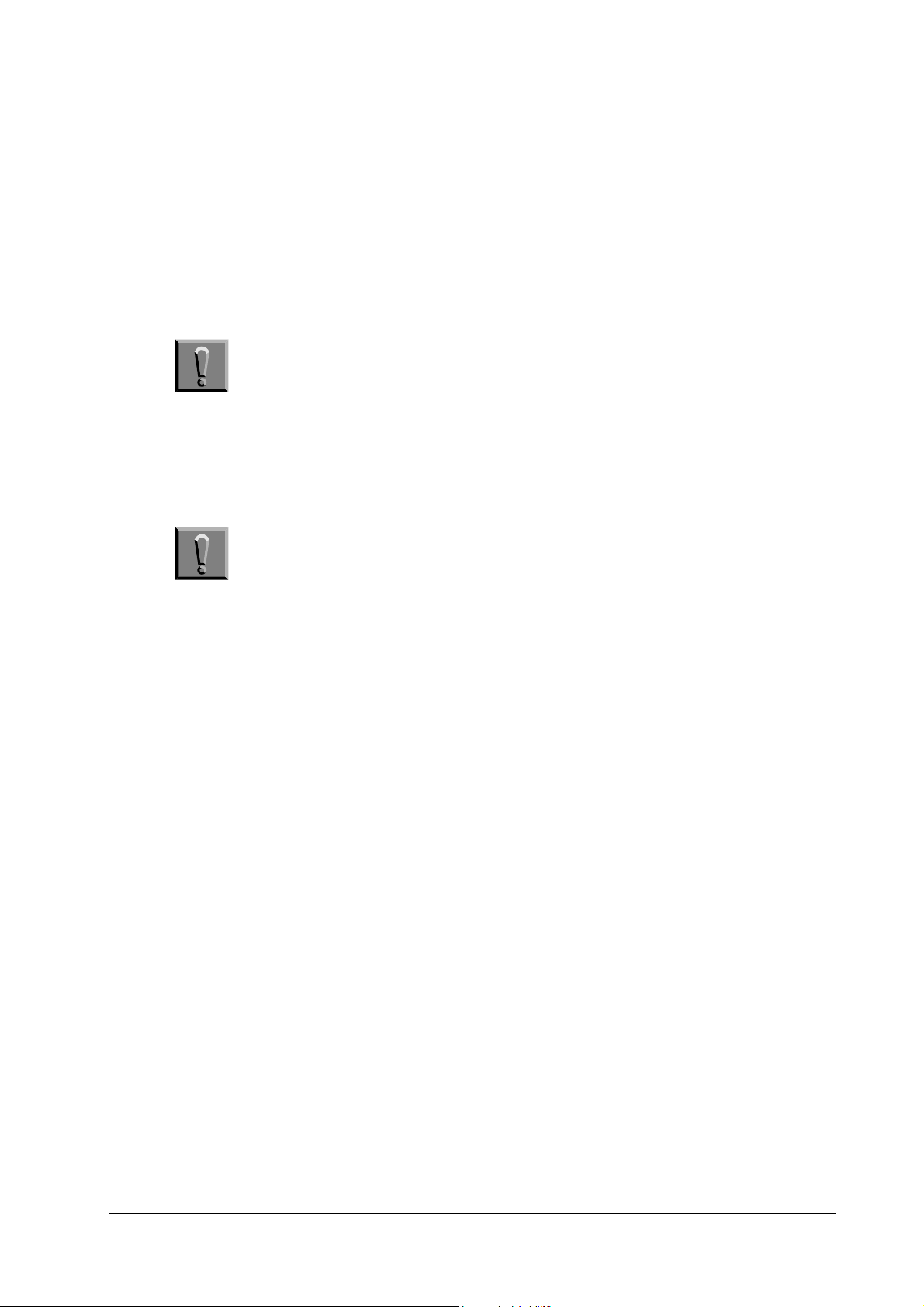
Open the top cover. The toner container must be removed first: Pull the toner container release lever as below. Pull the toner container slowly up. To avoid toner adhering from spilling, keep it as level as possible.
Toner container
Release lever
After removing the toner container, remove the developer’s connector from the
printer. Then, while pressing the developer release lever towards the front of the
printer, remove the developer unit.
FS-6700
5-3
Page 4
Disassembly
Disassembly: Main unit printer
Note After removing the developer, seal it in the protective bag and place it
on a flat sur-face. Do not place the developer in a dusty area. If you
ship the developer, pack it in the shipping container specifically supplied with the printer. See Shipping the de-veloper unit on page 5-8.
Also do not touch the developing roller of the developer. Do not place
floppy disks near the developer.
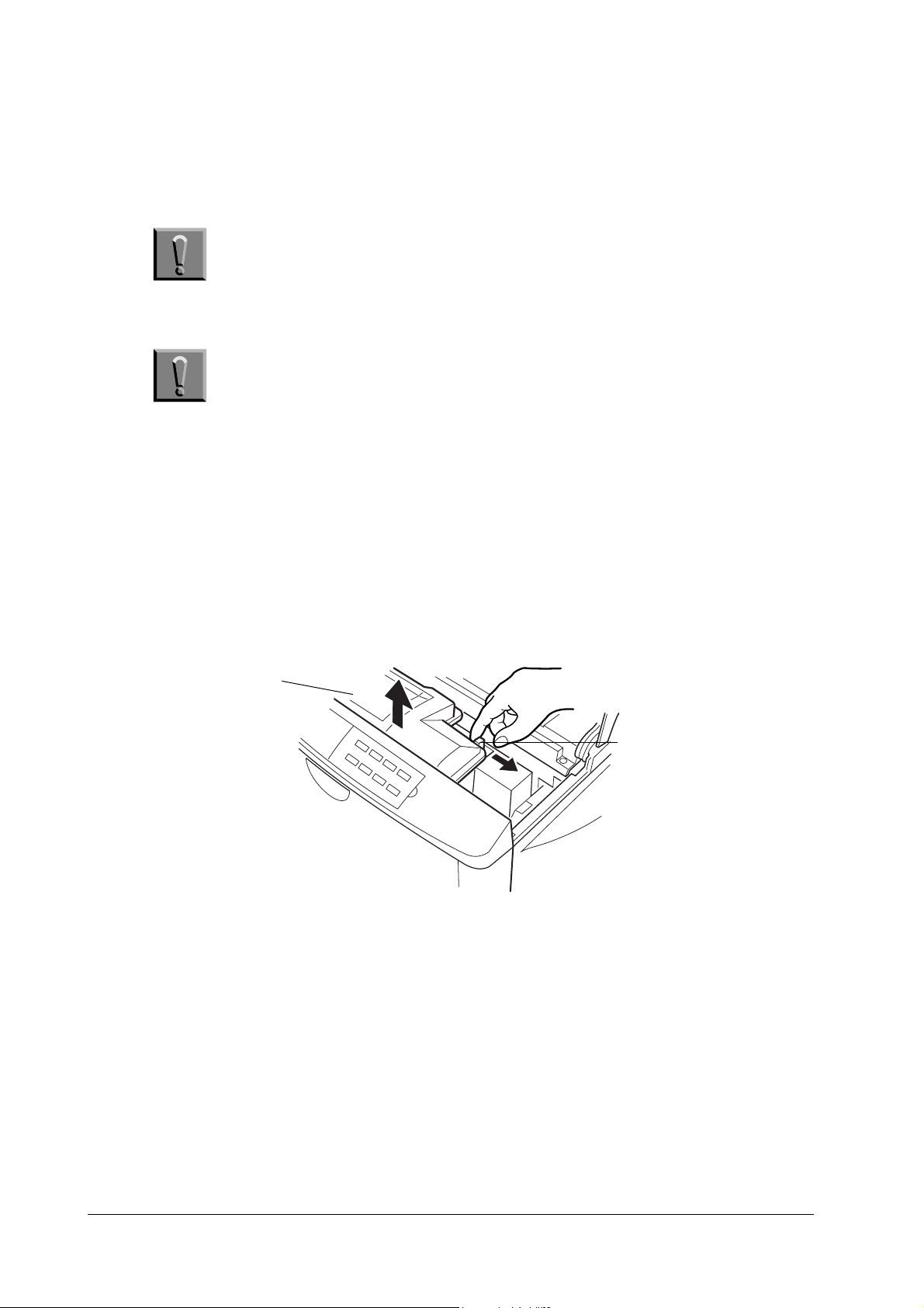
Shipping the developer unit
If the developer unit is shipped (the developer must be shipped separately if the
printer is shipped), it must be fit in the shipping container supplied originally with
the printer.
Shipping
container
First, flap the magnet roller protective cover down. Put the developer unit in the
plastic bag supplied with the shipping container. Put the developer unit into the
shipping container.
Installing a new developer
Use a developer unit DV-25 for replacement. Produce the developer unit from the
protective bag.
5-4
FS-6700
Page 5
Disassembly
Disassembly: Main unit printer
Flap the magnet roller protective cover up.
1
Protective
cover
Install the developer using the reverse manner of removing the developer
explained above. Connect the developer connector.
Removing the paper feed unit
The paper feed unit can be removed from the printer without using tools. First, be
sure to remove the paper cassette entirely out. Otherwise, the paper feed unit will
not come out.
To remove the paper feed unit, first remove the paper cassette out. While holding
and pushing the locking tabs at both sides of the paper feed unit, draw the paper
feed unit all the way out.
Locking tab
1. The protective cover is not provided with the developer unit that is originally supplied with the printer.
FS-6700
5-5
Page 6
Disassembly
Disassembly: Main unit printer
Removing the transfer roller
Before removing the transfer roller, remove the paper feed unit out of the printer.
Caution Do not touch the transfer roller (sponge) surface. Oil and dust (parti-
cles of paper, etc.) on the transfer roller can significantly deteriorate
the print quality (white spots, etc.).
Remove the transfer roller cover. Facing front the paper feed unit, move it to left.
The transfer roller is held in place by two axle holders that hold the roller axle at
both ends. Hold and pull the gear at the right end of the roller up, then remove the
left end.
Transfer roller cover
Transfer
roller
Cleaning the transfer roller
To clean the transfer roller, hold it by its gear so that the roller hangs down horizon-tally. Use a vacuum cleaner, moving nozzle along the roller, but do not let the
nozzle directly touch on the roller. Thoroughly clean the entire surface of the roller.
Rreplacing the transfer roller
Carefully clean the left side (facing the front of the paper feed unit) axle end before
replacing the transfer roller. This end of the axle is directly applied with the high
voltage transfer bias.
5-6
FS-6700
Page 7
Disassembly
Disassembly: Main unit printer
Removing the registration rollers
Before removing the registration rollers, remove the paper feed unit out of the
printer. To remove the paper feed unit, see page 5-5,
.
unit
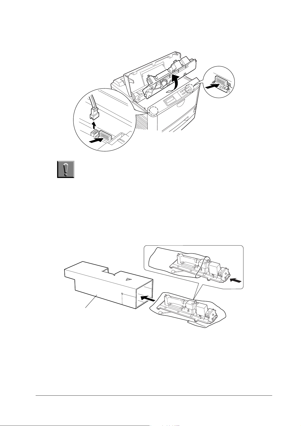
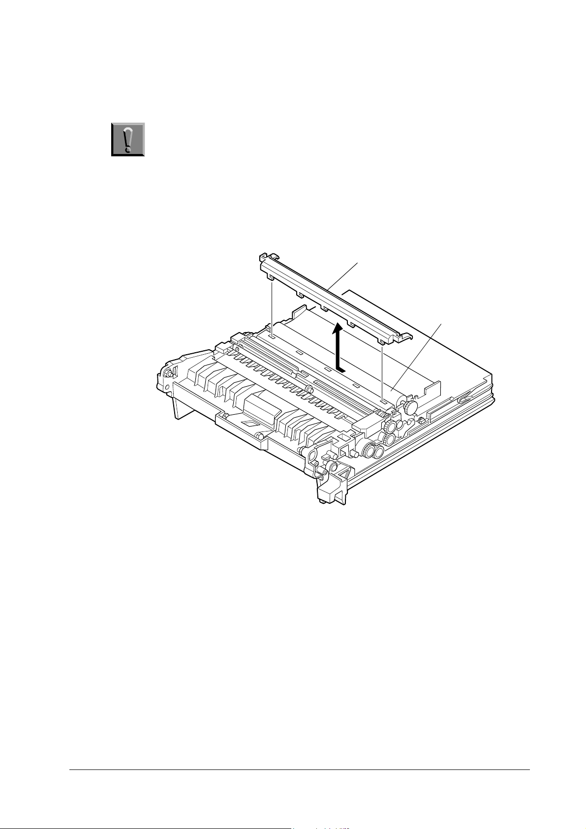
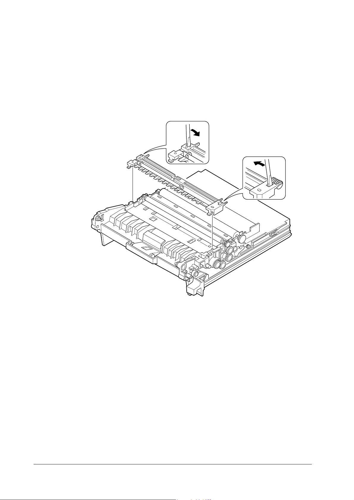
Remove the registration rollers cover. The cover is locked by two catches that lock
it onto the paper feed unit. These catches can be accessed through the holes on the
cover. Insert a screw driver as shown below and release the locks.
Removing the paper feed
FS-6700
5-7
Page 8

Disassembly
Disassembly: Main unit printer
Remove the coil springs that are used to secure and press the top (metal) registration roller towards the bottom (rubber) registration roller underneath.
Top regist. roller
Top r e g i st .
roller
Removing the drum unit
Caution Before removing the drum unit, be sure to remove the developer unit
and draw out the paper feed unit half way. Do not attempt to forcibly
pull out the drum without first having done all of these procedures.
1—Remove
this screw and
pull out the
drum unit.
5-8
3—Remove the
developer unit.
2—Draw the feed
unit half way out.
FS-6700
Page 9

Disassembly
Disassembly: Main unit printer
Caution Store the drum unit in a clear, clean place, not exposed to a strong
light source. Seal it in a protective bag. Avoid bump the drum surface
onto hard objects.
Replacing the drum unit
To replace the drum unit into the printer, be sure to align the guides and rails on
the drum unit with each other. Do not force to slide the drum unit in unless they
are properly aligned with each other.
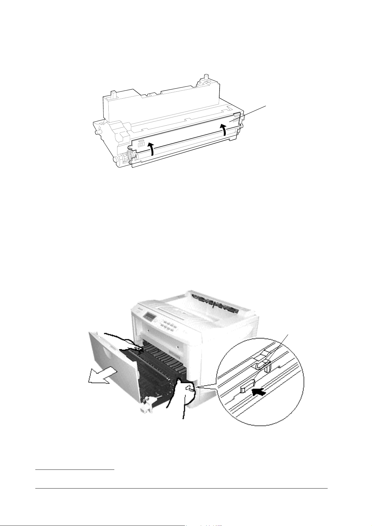
Main charger unit
Pull the main charger until it stops. While pushing the (white) locking peg inwards the printer, pull the main charger unit all the way out.
The main charger unit is explained on page 3-5,
Main charger unit
Main charger
unit
in chapter 3.
Lock peg
FS-6700
5-9
Page 10

Disassembly
Disassembly: Main unit printer
Top side cover
Open the toner container access door. Remove two screws ➊. While holding the
spring-loaded back side cover to open, pull the back plane of the top cover away
from the printer, then pull it upwards to remove.
Removing covers
The left and right side covers are snapped onto the chassis by catches and holes. No
screws are used. To remove the left and right side covers, release those catches and
holes at the front and the rear from each other, by inserting a small flat blade
screw driver between the cover and the chassis. Then, free the catches at the bottom by lowering the top side of the cover downwards.
Right cover
Left cover
5-10
FS-6700
Page 11

Disassembly
Disassembly: Main unit printer
Removing front cover
Remove the two screws ➊ at the front side. Detach the catches at the left and right
bottom of the cover as marked by circles below. To disengage these catches, proceed
to the next step.
Remove the ground wire ➊ and the connector ➋ below. Disengage the catches at
the left and right (shown) bottom of the cover.
FS-6700
5-11
Page 12

Removing the main motor
Disassembly
Disassembly: Main unit printer
Remove the right side cover first (page 5-10,
screws ➊. Then, remove the connector.
Removing covers
). Remove the four
Removing the drive assembly
Remove the right side cover first (page 5-10,
Removing covers
). Remove the five
screws ➊. Remove the connectors ➋ to ➐. Remove the drive assembly.
5-12
FS-6700
Page 13

Disassembly
Disassembly: Main unit printer
Removing the fuser unit
Remove the left and right covers (page 5-10,
Warning The fuser is hot after the printer was running. Wait until it cools down.
Removing covers
).
Detach all connectors from the fuser unit first. Remove the four screws ➊. Pull out
the fuser unit from the printer.
Removing the heater lamp
Warning The heater is extremely hot immediately after the printer was run-
ning. Allow substantial period of time until it cools down. Also, the
heater is fragile: Handle it with great care.
Remove the two screws ➊. Remove the cover from the fuser unit.
FS-6700
5-13
Page 14

Disassembly
Disassembly: Main unit printer
Remove the four screws ➊ and remove the fuser top cover. Remove the heater
lamp.
Note Do not directly touch on the heater lamp. Finger prints on the heater’s
outer surface can prevent proper fusing of toner on paper.
To install a new heater lamp, be sure that the lamp terminal (end) ➋ is properly
hitched by the fuser terminal ➊.
Installing the fuser roller
Remove the four screws to remove the cover. When lifting the cover, hold the heat
roller so as not to drop the roller.
To remove the heat (metal) roller, first remove “plate fuser up” by using a small
flat-blade screwdriver as shown below.
Note Special care should be taken not to let the screwdriver go too far into
the hole. Such an action can irrevocably damage the roller surface.
5-14
FS-6700
Page 15

Disassembly
Disassembly: Main unit printer
Heat roller
plate fuser up
Removing the thermistor and thermal cutout
Thermistor
Thermal cutout
FS-6700
5-15
Page 16

Disassembly
Disassembly: Main unit printer
Replacing the heat roller
To replace the heat roller, align the positioning keys on both collars so that they
face the paper input side (the drum unit side) [horizontally].
Then insert the heat roller retainer back in place.
Keys
roller heat
Removing the controller box
Before removing the controller box, several parts must be removed first. Refer to
the following pages and refer to the section titled as follows.
page 5-3,
•
page 5-8,
•
page 5-10,
•
page 5-10,
•
page 5-11,
•
Remove the screw ➊ below. This also disengages the ground wire.
Removing the developer unit
Removing the drum unit
Top side cover
Removing covers
Removing front cover
5-16
FS-6700
Page 17

Disassembly
Disassembly: Main unit printer
Remove the high-voltage board at the left side of the printer. To do this, remove the
three screws ➊.
FS-6700
Remove the two screws ➊ at the left side of the printer. Disengage the connectors.
5-17
Page 18

Disassembly
Disassembly: Main unit printer
Remove the two screws on the front side. Hold the upper frame and lift to remove.
On the controller box, remove the six screws ➊ on top and the two screws ➋ at the
rear side. Remove the cover.
5-18
FS-6700
Page 19

Disassembly
Disassembly: Main unit printer
Removing the face-down pulley assembly
Remove the screw ➊ to remove the face-down pulley assembly.
Face-down
assembly
FS-6700
5-19
Page 20

Disassembly: Option paper feeder
5.3 Disassembly: Option paper feeder
This section describes instructions on how to disassemble the option paper feeder
PF-25 for the FS-6700 printer. Before proceeding;
Disconnect power from the printer
•
Remove the printer (and the duplexer if installed).
•
Removing the feed roller
Remove the paper cassette from the option paper feeder. Then remove the paper
feed roller by unlatching it at both ends.
8.cdr
Disassembly
Removing the top cover
Remove the six screws ➊ on the top cover.
9.cdr
5-20
FS-6700
Page 21

Disassembly
Disassembly: Option paper feeder
Removing the motor assembly
To remove the motor assembly, remove the two screws ➊ atop that secure the
motor bracket and the one screw ➋ at the bottom.
10.cdr
The following picture shows the motor assembly and the gears mounted on the
motor bracket.
FS-6700
5-21
Page 22

This page left blank intentionally
Disassembly
Disassembly: Option paper feeder
5-22
FS-6700
 Loading...