

Page 1
SERVICE
MANUAL
Published in Oct. ’02
Page 2

Revision history
Version Data Replaced pages Remarks
1.0
1.1
1.2
8-Oct-2002
17-Feb-2003
10-Mar-2003
1-1-3
1-7-1, 1-7-2, 1-7-4
-
-
Page 3

Safety precautions
This booklet provides safety warnings and precautions for our service personnel to ensure the safety of
their customers, their machines as well as themselves during maintenance activities. Service personnel
are advised to read this booklet carefully to familiarize themselves with the warnings and precautions
described here before engaging in maintenance activities.
Page 4
Safety warnings and precautions
Various symbols are used to protect our service personnel and customers from physical danger and
to prevent damage to their property. These symbols are described below:
DANGER: High risk of serious bodily injury or death may result from insufficient attention to or incorrect
compliance with warning messages using this symbol.
WARNING:Serious bodily injury or death may result from insufficient attention to or incorrect compliance
with warning messages using this symbol.
CAUTION:Bodily injury or damage to property may result from insufficient attention to or incorrect
compliance with warning messages using this symbol.
Symbols
The triangle ( ) symbol indicates a warning including danger and caution. The specific point
of attention is shown inside the symbol.
General warning.
Warning of risk of electric shock.
Warning of high temperature.
indicates a prohibited action. The specific prohibition is shown inside the symbol.
General prohibited action.
Disassembly prohibited.
indicates that action is required. The specific action required is shown inside the symbol.
General action required.
Remove the power plug from the wall outlet.
Always ground the copier.
Page 5
1. Installation Precautions
WARNING
•Do not use a power supply with a voltage other than that specified. Avoid multiple connections to
one outlet: they may cause fire or electric shock. When using an extension cable, always check
that it is adequate for the rated current. ............................................................................................
•Connect the ground wire to a suitable grounding point. Not grounding the copier may cause fire or
electric shock. Connecting the earth wire to an object not approved for the purpose may cause
explosion or electric shock. Never connect the ground cable to any of the following: gas pipes,
lightning rods, ground cables for telephone lines and water pipes or faucets not approved by the
proper authorities. .............................................................................................................................
CAUTION:
•Do not place the copier on an infirm or angled surface: the copier may tip over, causing injury. .....
•Do not install the copier in a humid or dusty place. This may cause fire or electric shock. ..............
•Do not install the copier near a radiator, heater, other heat source or near flammable material.
This may cause fire. ..........................................................................................................................
•Allow sufficient space around the copier to allow the ventilation grills to keep the machine as cool
as possible. Insufficient ventilation may cause heat buildup and poor copying performance. ..........
•Always handle the machine by the correct locations when moving it. ..............................................
•Always use anti-toppling and locking devices on copiers so equipped. Failure to do this may
cause the copier to move unexpectedly or topple, leading to injury..................................................
•Avoid inhaling toner or developer excessively. Protect the eyes. If toner or developer is
accidentally ingested, drink a lot of water to dilute it in the stomach and obtain medical attention
immediately. If it gets into the eyes, rinse immediately with copious amounts of water and obtain
medical attention. ..............................................................................................................................
•Advice customers that they must always follow the safety warnings and precautions in the copier’s
instruction handbook. ........................................................................................................................
Page 6
2. Precautions for Maintenance
WARNING
•Always remove the power plug from the wall outlet before starting machine disassembly...............
•Always follow the procedures for maintenance described in the service manual and other related
brochures. .........................................................................................................................................
•Under no circumstances attempt to bypass or disable safety features including safety
mechanisms and protective circuits. .................................................................................................
•Always use parts having the correct specifications...........................................................................
•Always use the thermostat or thermal fuse specified in the service manual or other related
brochure when replacing them. Using a piece of wire, for example, could lead to fire or other
serious accident. ...............................................................................................................................
•When the service manual or other serious brochure specifies a distance or gap for installation of a
part, always use the correct scale and measure carefully. ...............................................................
•Always check that the copier is correctly connected to an outlet with a ground connection. ............
•Check that the power cable covering is free of damage. Check that the power plug is dust-free. If
it is dirty, clean it to remove the risk of fire or electric shock. ............................................................
•Never attempt to disassemble the optical unit in machines using lasers. Leaking laser light may
damage eyesight...............................................................................................................................
•Handle the charger sections with care. They are charged to high potentials and may cause
electric shock if handled improperly..................................................................................................
CAUTION
•Wear safe clothing. If wearing loose clothing or accessories such as ties, make sure they are
safely secured so they will not be caught in rotating sections...........................................................
•Use utmost caution when working on a powered machine. Keep away from chains and belts. .......
•Handle the fixing section with care to avoid burns as it can be extremely hot. .................................
•Check that the fixing unit thermistor, heat and press rollers are clean. Dirt on them can cause
abnormally high temperatures...........................................................................................................
•Do not remove the ozone filter, if any, from the copier except for routine replacement....................
Page 7
•Do not pull on the AC power cord or connector wires on high-voltage components when removing
them; always hold the plug itself. ......................................................................................................
•Do not route the power cable where it may be stood on or trapped. If necessary, protect it with a
cable cover or other appropriate item. ..............................................................................................
•Treat the ends of the wire carefully when installing a new charger wire to avoid electric leaks........
•Remove toner completely from electronic components. ...................................................................
•Run wire harnesses carefully so that wires will not be trapped or damaged. ...................................
•After maintenance, always check that all the parts, screws, connectors and wires that were
removed, have been refitted correctly. Special attention should be paid to any forgotten
connector, trapped wire and missing screws. ..................................................................................
•Check that all the caution labels that should be present on the machine according to the
instruction handbook are clean and not peeling. Replace with new ones if necessary. ...................
•Handle greases and solvents with care by following the instructions below: ....................................
· Use only a small amount of solvent at a time, being careful not to spill. Wipe spills off completely.
· Ventilate the room well while using grease or solvents.
· Allow applied solvents to evaporate completely before refitting the covers or turning the main
switch on.
· Always wash hands afterwards.
•Never dispose of toner or toner bottles in fire. Toner may cause sparks when exposed directly to
fire in a furnace, etc...........................................................................................................................
•Should smoke be seen coming from the copier, remove the power plug from the wall outlet
immediately. ......................................................................................................................................
3. Miscellaneous
WARNING
•Never attempt to heat the drum or expose it to any organic solvents such as alcohol, other than
the specified refiner; it may generate toxic gas.................................................................................
Page 8

CONTENTS
1-1 Specifications
1-1-1 Specifications ....................................................................................................................................... 1-1-1
1-1-2 Parts names ......................................................................................................................................... 1-1-4
(1) Printer............................................................................................................................................. 1-1-4
(2) Operation panel.............................................................................................................................. 1-1-5
1-1-3 Machine cross section.......................................................................................................................... 1-1-6
1-1-4 Drive system ........................................................................................................................................ 1-1-7
(1) Drive system................................................................................................................................... 1-1-7
1-2 Handling Precautions
1-2-1 Process unit ......................................................................................................................................... 1-2-1
1-2-2 Toner container .................................................................................................................................... 1-2-1
1-2-3 Installation environment ....................................................................................................................... 1-2-1
1-3 Installation
1-3-1 Unpacking and installation ................................................................................................................... 1-3-1
(1) Installation procedure ..................................................................................................................... 1-3-1
1-3-2 Installing expansion memory (optional)................................................................................................ 1-3-8
1-3-3 Installing network interface card (optional)........................................................................................... 1-3-9
1-3-4 Installing hard disk unit (optional)....................................................................................................... 1-3-10
1-3-5 Installing memory card (optional) ....................................................................................................... 1-3-11
FS-6020
1-4 Service Mode
1-4-1 Service mode ....................................................................................................................................... 1-4-1
(1) Executing service mode ................................................................................................................. 1-4-1
1-5 Troubleshooting
1-5-1 Paper misfeed detection ...................................................................................................................... 1-5-1
(1) Paper misfeed indication ................................................................................................................ 1-5-1
1-5-2 Self-diagnosis....................................................................................................................................... 1-5-2
(1) Self-diagnostic function .................................................................................................................. 1-5-2
(1-1) Error code 2000 [E1] (main motor error) ............................................................................... 1-5-3
(1-2) Error code 4000 [E2] (polygon motor error)........................................................................... 1-5-4
(1-3) Error code 4200 [E3] (laser output error)............................................................................... 1-5-5
(1-4) Error code 6000 [E4] (fixing heater lamp/fixing thermistor error)........................................... 1-5-6
(1-5) Error code 6020 [A2] (abnormally high fixing temperature error) .......................................... 1-5-7
(1-6) Error code 6400 [A0] (fixing heater lamp control zero-cross signal detection error) ............. 1-5-8
(1-7) Error code F0 [F0]
(communication error between the operation panel PWB and main PWB)........................... 1-5-8
(1-8) Error code F010 [F1] (code ROM checksum error)............................................................... 1-5-9
(1-9) Error code F020 [F2] (main PWB RAM checksum error) .................................................... 1-5-10
(1-10) Error code F030 [F3] (main PWB controller error)............................................................... 1-5-11
(1-11) Error code F040 [E0]
(communication error between engine/high voltage PWB and main PWB controller)......... 1-5-11
(1-12) Error code F050 [E6] (engine/high-voltage flash memory checksum error)........................ 1-5-12
(1-13) Error code F080 [E6] (system firmware download error)..................................................... 1-5-12
(1-14) Error code 0420 [C0]
(serial communication error between paper feeder and engine/high voltage PWB) ........... 1-5-13
(1-15) Error code 1210 [C2] (duplexer slide guide home position detection error) ........................ 1-5-15
(1-16) Error code 2610 [B2] (paper feeder 1 feed motor error)...................................................... 1-5-16
(1-17) Error code 2620 [B3] (paper feeder 2 feed motor error)...................................................... 1-5-16
(1-18) Error code 2630 [B4] (paper feeder 3 feed motor error)...................................................... 1-5-16
(1-19) Error code 2640 [B5] (paper feeder 4 feed motor error)...................................................... 1-5-16
1-1-1
Page 9

FS-6020
1-5-3 Electrical problems ............................................................................................................................. 1-5-17
(1) Even if the top cover is closed, the message “Close top cover” remains.............................. 1-5-17
(2) Even if the rear cover is closed, the message “Close rear cover” remains.......................... 1-5-17
(3) The message “Paper Jam” remains. .......................................................................................... 1-5-17
(4) The message “Face-down tray paper full” remains. ........................................................ 1-5-17
(5) The paper size is not recognized as the size set with the paper size dial of the cassette............ 1-5-18
(6) The message “Self test” remains when the printer is started................................................. 1-5-18
(7) No message is displayed when the power switch is turned on. (All dots of LCD are on.) ............ 1-5-18
(8) No message is displayed when the power switch is turned on. (All dots of LCD are off.) ............ 1-5-18
1-5-4 Image formation problems ................................................................................................................. 1-5-19
(1) No image appears. (entirely white) ............................................................................................... 1-5-20
(2) No image appears. (entirely black) ............................................................................................... 1-5-20
(3) Image is light as a whole. ............................................................................................................. 1-5-21
(4) Background is gray. ...................................................................................................................... 1-5-21
(5) A white line appears longitudinally. .............................................................................................. 1-5-21
(6) A black line appears longitudinally. .............................................................................................. 1-5-22
(7) A black line appears laterally. ....................................................................................................... 1-5-22
(8) One side of the print image is darker than the other. ................................................................... 1-5-22
(9) Black dots appear on the image. .................................................................................................. 1-5-23
(10) Image blurs. .................................................................................................................................. 1-5-23
(11) Image is displaced toward the rear side of paper. ........................................................................ 1-5-23
(12) Paper creases. ............................................................................................................................. 1-5-24
(13) Offset occurs. ............................................................................................................................... 1-5-24
(14) Image is partly missing. ................................................................................................................ 1-5-24
(15) Fixing is poor. ............................................................................................................................... 1-5-25
(16) Image becomes dim. .................................................................................................................... 1-5-25
(17) Image is inclined. .......................................................................................................................... 1-5-25
1-6 Assembly and Disassembly
1-6-1 Precautions for assembly and disassembly ......................................................................................... 1-6-1
(1) Precautions ..................................................................................................................................... 1-6-1
1-6-2 Covers .................................................................................................................................................. 1-6-2
(1) Detaching and refitting the top cover .............................................................................................. 1-6-2
(2) Detaching and refitting the left cover .............................................................................................. 1-6-3
(3) Detaching and refitting the right cover ............................................................................................ 1-6-4
(4) Detaching and refitting the rear cover ............................................................................................ 1-6-5
(5) Detaching and refitting the front cover ............................................................................................ 1-6-6
1-6-3 Paper feed section ............................................................................................................................... 1-6-7
(1) Detaching and refitting the feed and pickup rollers ........................................................................ 1-6-7
(2) Detaching and refitting the paper feed unit..................................................................................... 1-6-8
(3) Detaching and refitting the MP tray feed roller ............................................................................. 1-6-10
(4) Detaching and refitting the MP tray feed unit ............................................................................... 1-6-11
(5) Detaching and refitting the retard roller ........................................................................................ 1-6-13
(6) Detaching and refitting the drive assembly ................................................................................... 1-6-14
1-6-4 Laser scanner unit section ................................................................................................................. 1-6-15
(1) Detaching and refitting the laser scanner unit .............................................................................. 1-6-15
1-6-5 Process unit section ........................................................................................................................... 1-6-16
(1) Detaching and refitting the main charger unit ............................................................................... 1-6-16
1-6-6 Transfer/separation section................................................................................................................ 1-6-17
(1) Detaching and refitting the transfer roller and separation charger unit......................................... 1-6-17
1-6-7 Fixing section ..................................................................................................................................... 1-6-18
(1) Detaching and refitting the fixing unit ........................................................................................... 1-6-18
(2) Detaching and refitting the fixing heater lamp .............................................................................. 1-6-19
(3) Detaching and refitting the heat roller ........................................................................................... 1-6-21
(4) Detaching and refitting the press roller ......................................................................................... 1-6-22
(5) Detaching and refitting the fixing thermistor and separator .......................................................... 1-6-23
(6) Detaching and refitting the fixing thermostat ................................................................................ 1-6-24
1-1-2
Page 10

1-6-8 PWBs ................................................................................................................................................. 1-6-25
(1) Detaching and refitting the main PWB.......................................................................................... 1-6-25
(2) Detaching and refitting the engine/high voltage PWB .................................................................. 1-6-26
(3) Detaching and refitting the power source PWB............................................................................ 1-6-29
1-7 Firmware
1-7-1 Downloading firmware.......................................................................................................................... 1-7-1
(1) Format for the firmware files........................................................................................................... 1-7-1
(2) Downloading firmware via the parallel interface............................................................................. 1-7-2
(3) Downloading firmware using the memory card .............................................................................. 1-7-3
(4) Downloading the message data ..................................................................................................... 1-7-5
2-1 Mechanical construction
2-1-1 Paper feed/conveying section .............................................................................................................. 2-1-1
(1) Paper feed section/paper cassette................................................................................................. 2-1-1
(2) MP tray feed section....................................................................................................................... 2-1-3
(3) Conveying section .......................................................................................................................... 2-1-4
2-1-2 Process unit section ............................................................................................................................. 2-1-5
(1) Development section...................................................................................................................... 2-1-5
(2) Main charger/drum section............................................................................................................. 2-1-7
2-1-3 Laser scanner unit section ................................................................................................................... 2-1-9
(1) Laser scanner unit.......................................................................................................................... 2-1-9
2-1-4 Transfer/separation section................................................................................................................ 2-1-12
2-1-5 Cleaning section................................................................................................................................. 2-1-13
2-1-6 Fixing section ..................................................................................................................................... 2-1-15
2-1-7 Face-down eject/feedshift section ...................................................................................................... 2-1-17
FS-6020
2-2 Electrical Parts Layout
2-2-1 Electrical parts layout ........................................................................................................................... 2-2-1
(1) Main frame...................................................................................................................................... 2-2-1
(2) Process unit, laser scanner and fixing unit..................................................................................... 2-2-3
2-3 Operation of the PWBs
2-3-1 Power source PWB .............................................................................................................................. 2-3-1
2-3-2 Engine/high voltage PWB .................................................................................................................... 2-3-3
(1) Fixing heater lamp control circuit.................................................................................................... 2-3-4
(2) Fixing heater lamp lighting runaway prevention - fixing thermistor
disconnection detection circuit........................................................................................................ 2-3-5
(3) Interlock switch - eco-power circuit................................................................................................. 2-3-6
(4) Optional equipment identification circuit......................................................................................... 2-3-7
2-3-3 Main PWB .......................................................................................................................................... 2-3-11
2-4 Appendixes
Timing chart No. 1 Paper cassette feeding, two A4 size papers ................................................................. 2-4-1
Timing chart No. 2 Paper cassette feeding, two A4R size papers............................................................... 2-4-2
Timing chart No. 3 Paper cassette feeding, two A3 size papers ................................................................. 2-4-3
Timing chart No. 4 Paper cassette feeding, two B5 size papers ................................................................. 2-4-4
Timing chart No. 5 Paper cassette feeding, two B4 size papers ................................................................. 2-4-5
Timing chart No. 6 Paper cassette feeding, two letter size papers.............................................................. 2-4-6
Timing chart No. 7 Paper cassette feeding, two letter R size papers .......................................................... 2-4-7
Timing chart No. 8 Paper cassette feeding, two legal size papers .............................................................. 2-4-8
Timing chart No. 9 Paper cassette feeding, two ledger size papers............................................................ 2-4-9
Timing chart No. 10 MP tray feeding, two A4 size papers ......................................................................... 2-4-10
Timing chart No. 11 MP tray feeding, two A4R size papers ...................................................................... 2-4-11
Timing chart No. 12 MP tray feeding, two A3 size papers ......................................................................... 2-4-12
Timing chart No. 13 MP tray feeding, two B5 size papers ......................................................................... 2-4-13
Timing chart No. 14 MP tray feeding, two B4 size papers ......................................................................... 2-4-14
Timing chart No. 15 MP tray feeding, two letter R size papers.................................................................. 2-4-15
1-1-3
Page 11

FS-6020
Timing chart No. 16 MP tray feeding, two letter size papers ..................................................................... 2-4-16
Timing chart No. 17 MP tray feeding, two legal size papers...................................................................... 2-4-17
Timing chart No. 18 MP tray feeding, two ledger size papers ................................................................... 2-4-18
Timing chart No. 19 MP tray feeding, two custom size papers.................................................................. 2-4-19
Wiring diagram ............................................................................................................................................. 2-4-20
Repetitive defects gauge .............................................................................................................................. 2-4-21
1-1-4
Page 12

This page is intentionally left blank.
Page 13

FS-6020
1-1-1 Specifications
Type................................................ Desktop
Printing system .............................. Electrophotographic printing
Paper..............................................Cassette: Plain paper (60 to 90 g/m
Recycled paper (60 to 90 g/m
Thick paper (90 to 105 g/m2)
MP tray: Plain paper (60 to 90 g/m
Recycled paper (60 to 90 g/m
Thick paper (90 to 200 g/m
2
Special paper: Transparencies, labels, envelopes, postcards, tracing paper
Printing sizes.................................. A4 (297 × 420 mm)
B4 (257 × 364 mm)
A4R (210 × 297 mm)
A4 (297 × 210 mm)
B5 (257 × 182 mm)
Folio (210 × 182 mm)
Ledger (11" × 17")
Legal (8.5" × 14")
Letter-R (11" × 8.5")
Letter (11" × 8.5")
Non-standard size (148 to 297 mm × 210 to 432 mm: cassette)
Non-standard size (70 to 148 mm × 297 to 450 mm: MP tray)
Print speed .....................................Cassette (Values within [ ] are speed of printing through an optional duplexer DU-
400.)
A4: 20 pages/minutes [20 images/minutes]
A3: 11 pages/minutes [11 images/minutes]
B4: 12 pages/minutes [12 images/minutes]
A4R: 15 pages/minutes [15 images/minutes]
B5: 17 pages/minutes [17 images/minutes]
A5: 20 pages/minutes [20 images/minutes]
Ledger: 11 pages/minutes [11 images/minutes]
Legal: 13 pages/minutes [13 images/minutes]
Letter: 20 pages/minutes [20 images/minutes]
Letter-R: 16 pages/minutes [16 images/minutes]
MP tray (in cassette mode)
A4: 20 pages/minutes
A3: 11 pages/minutes
B4: 12 pages/minutes
A4R: 15 pages/minutes
B5: 17 pages/minutes
A5: 20 pages/minutes
Ledger: 11 pages/minutes
Legal: 13 pages/minutes
Letter: 20 pages/minutes
Letter-R: 16 pages/minutes
First print time ................................Standby mode: 22 seconds or less (A4) [when the EcoPower mode is on]
Sleep mode: 22 seconds or less (A4) [when the EcoPower mode is on]
Standby mode: 12 seconds or less (A4) [when the EcoPower mode is off]
Sleep mode: 22 seconds or less (A4) [when the EcoPower mode is off]
Warm-up time................................. Sleep mode: 28 seconds or less (room temperature 23 °C, 60 % RH)
Power on: 60 seconds or less (room temperature 23 °C, 60 % RH)
Paper feed system ......................... One universal type cassette, and one MP tray
Paper loading capacity................... Cassette: 250 sheets (75 g/m
MP tray: 100 sheets (75 g/m
Duplexer: No stack
Paper eject system.........................Face down; 250 sheets (75 g/m
Photoconductor .............................. OPC drum (diameter 30 mm)
Charging system ............................ Scorotron (positive charging)
Exposure light source.....................Semiconductor laser
Developing system......................... One-component dry developing (reverse developing)
Developer: One-component magnetic toner
Toner replenishing: Automatic from the toner container
2
)
2
)
2
)
2
)
)
2
, 0.1 µm)
2
, 0.1 µm)
2
, 0.1 µm) equipped with face-down paper full sensor
1-1-1
Page 14

FS-6020
Transfer system.............................. Roller transfer (negative charging)
Separation system .........................Small radius curvature separation and separation charger brush (positive charging)
Fixing system ................................. Heat roller system
Charge erasing system .................. Exposure by eraser lamp (LED)
Cleaning system.............................Counter blade
Controller hardware........................CPU: Power PC405 (200 MHz)
Code ROM: 4 MB (32 Mbit × 2)
Font ROM: 4 MB (32 Mbit × 1)
Main RAM: 16 MB in standard configuration (on-board); can be expanded to 144 MB
(standard 16 MB + 128 MB) at the maximum by adding optional expansion memory
Optional expansion RAM: 1 slot
100-pin DIMM (16, 32, 64 or 128 MB)
Interface ......................................... Parallel: High-speed (bi-directional), IEEE 1284 Nibble/ECP mode
USB: Full-Speed USB2.0
Serial (optional): RS-232C, maximum speed 115.2 Kbps
Serial interface board IB-11 must be installed.
Network (optional): 10 Base-TX/100 Base-TX/10 Base-2
Network interface card: IB-21 (10 Base-TX/100 Base-TX/10 Base-2)
Network interface card IB-21E (10 Base-TX/100 Base-TX)
Wireless LAN card IB-22 must be installed.
Controller software ......................... a) Emulation
(1) Standard
Line Printer
IBM Proprinter X24E
Epson LQ-850
KCGL
Diablo 630
PCL6 (PCL5e + PCLXL protocol class 2.0)
(2) Option
Japanese KPDL3 (PostScript 3 compatible) UG-13
b) Fonts:
(1) Western fonts
Bitmap fonts: 1 Line Printer bitmap fonts
Outline fonts: 80 outline fonts
79 bitmap emulate downloadable font: Kyocera Mita format/HP format
c) Graphic:
(1) Raster graphic:
75, 100, 150, *200, 300, 600* dpi
(*200 dpi is supported when the resolution is 600 dpi.)
(2) V ector graphic:
Line, Box, Circle, Arc, Fill pattern etc.
(3) Bar code:
One-dimensional bar code: 45 types
Two-dimensional bar code: 1 type (PDF-417)
(4) Text:
TEXT, RTXT etc.
(5) Others:
Macro, JOBx, Device setting etc.
d) Connectivity
plug & play, Windows 95/98/ME/NT4.0/2000/XP
SNMP (KM-NET viewer)
Smoothing ...................................... KIR: equivalent to 2400 dpi, two levels by On and Off
(Available only in 600 dpi mode or fast 1200 mode; On at the factory default setting)
Toner saving................................... EcoPrint mode
Resolution ...................................... Fast 1200 mode: 1800 × 600 dpi
600 dpi mode: 600 × 600 dpi
300 dpi mode: 300 × 300 dpi
(Fast 1200 mode at the factory default setting)
Gray scale ...................................... Fast 1200 mode: 220 levels
600 dpi mode: 203 levels
Dimensions ....................................Main unit: 467 × 410 × 310 mm/18
3
/8" × 161/8" × 123/16" (W × D × H)
Weight ............................................Main unit: 18 kg/39.7 lbs
1-1-2
Page 15

FS-6020
Power source ................................. 120 V AC, 60 Hz (U.S.A./Canada)
220-240 V AC, 50/60 Hz (European countries)
Power consumption ........................ Maximum: 961 W
Normal operating: 382 W
Ready: 21 W
EcoPower: 8 W
Current ........................................... 10.8 A: 21 W (U.S.A./Canada)
7.2 A: 21 W (European countries)
Noise .............................................. Printing: 54 dB(A)
Ready: 31 dB(A)
Options ........................................... Expansion memory (one of 16/32/64/128 MB 100-pin DIMM), KPLD3 upgrade kit UG-
13, memory card (CompactFlash), hard disk unit (Microdrive), network interface card
IB-20 (10 BASE-T/100BASE-TX/10BASE-2), network interface card IB-21E (10
BASE-T/100BASE-TX), wireless network interface card IB-22 (compatible to IEEE
802.11b), serial interface board IB-11, paper feeder PF-400 (250 sheets [60 to 105 g/
2
m
] × 1 cassette, A3, A4, A4R, A5, B4, B5, folio, ledger, legal, let5ter, and letter-R),
duplexer DU-400
1-1-3
Page 16
FS-6020
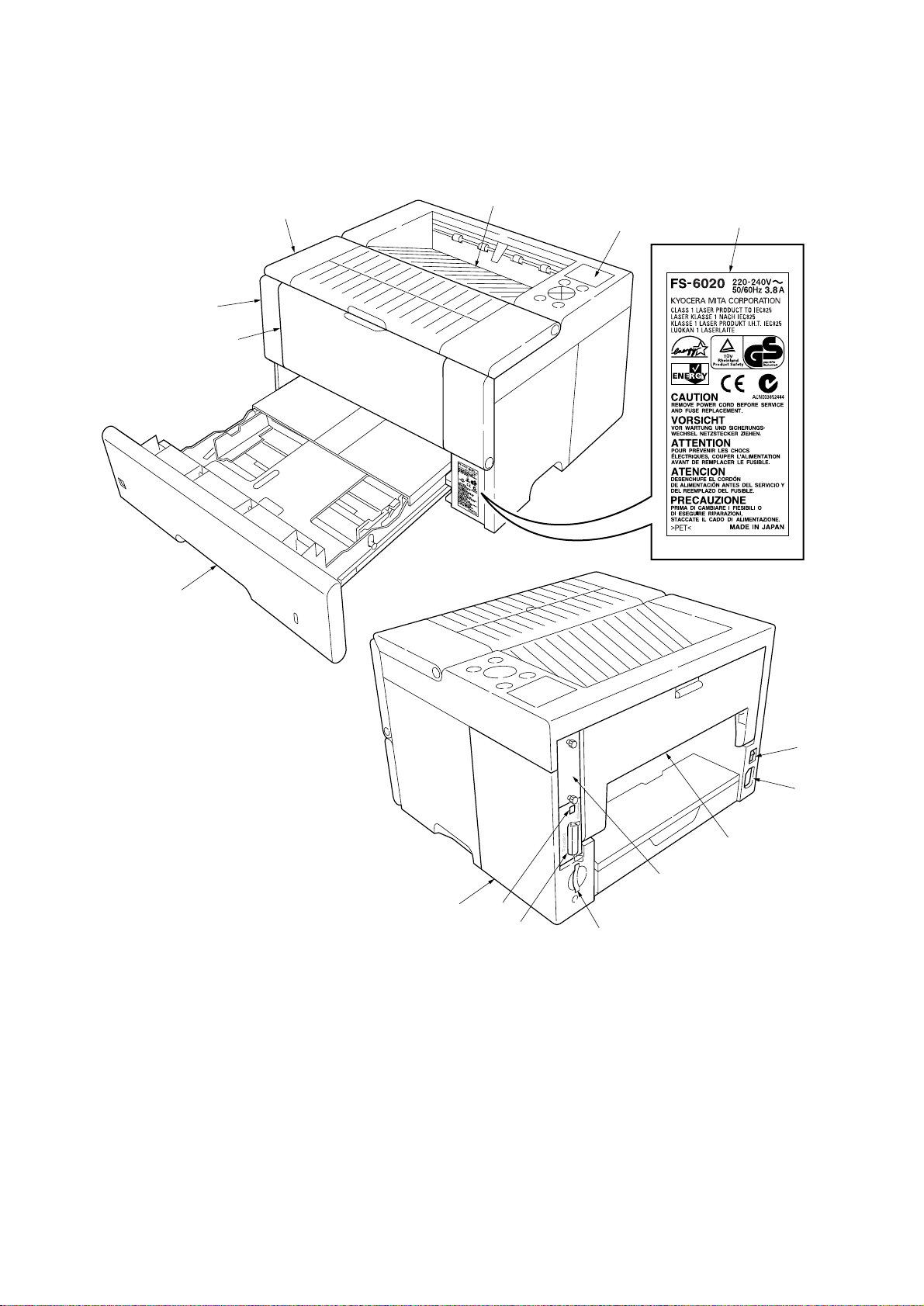
1-1-2 Parts names
(1) Printer
6
2
5
3
4
1
%
1 Operation panel
2 Front cover
3 Top cover
4 Face-down tray
5 MP tray
6 Paper cassette
7 Optional interface slot cover
8 Power switch
7
Figure 1-1-1
9 AC inlet
0 Rear cover
! Optional interface slot
@ Memory card slot
# Parallel interface
$ USB interface
% Caution label
$
#
8
9
0
!
@
1-1-4
Page 17
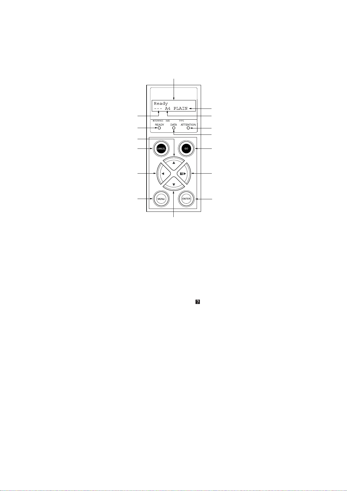
(2) Operation panel
2
FS-6020
1
4
3
5
!
9
#
0
1 Message display
2 Interface indicator
3 Paper size indicator
4 Paper type indicator
5 READY indicator
6 DATA indicator
7 ATTENTION indicator
8 ENTER key
@
Figure 1-1-2
7
6
%
$
8
9 CANCEL key
0 MENU key
! M key
@ N key
# O key
$
P key
% GO key
1-1-5
Page 18
FS-6020
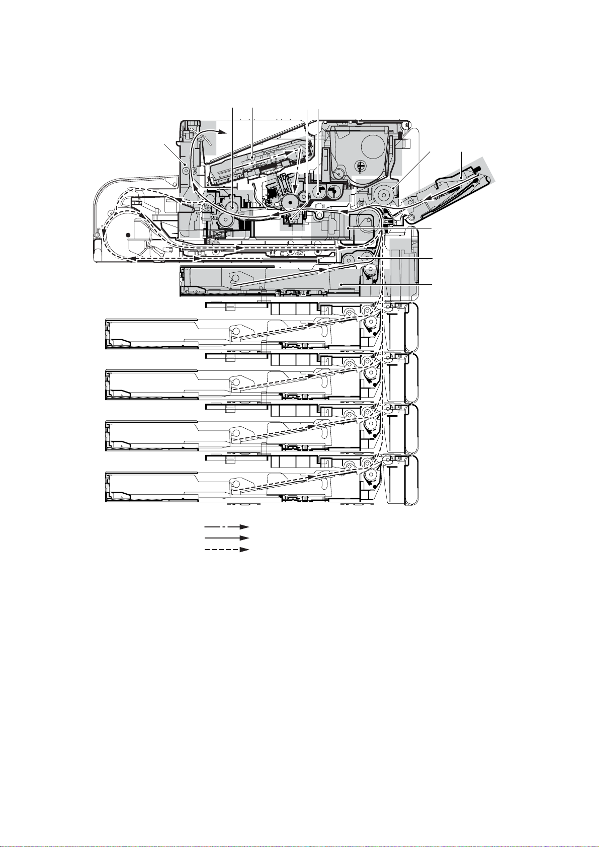
1-1-3 Machine cross section
0
69
8
7
5
4
3
2
1
1-1-6
Laser output path
Paper path
Paper path (optional paper feeder and duplexer)
Figure 1-1-3 Machine cross section
1 Paper cassette
2 Paper feed section
3 Conveying section
4 MP tray
5 MP tray feed section
6 Laser scanner unit section
7 Process unit section
8 Transfer/separation section
9 Fixing section
0 Face-down eject/feedshift section
Page 19
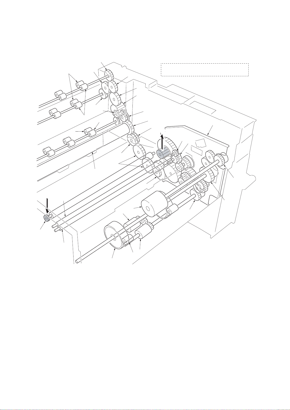
1-1-4 Drive system
(1) Drive system
FS-6020
6
A
5
2
‚
3
!
6
Œ
°
·
$
@
⁄
!
*
0
9
fl
^
fi
A Driving is linked with the process unit (drum).
#
A
8
7
(
1
&
¤
%
4
1 Drive assembly
2 Pinch roller
3 Face-down roller
4 Upper registration roller
5 Lower registration roller
6 Face-down roller gear Z18
7 Registration roller gear Z32-Z31
8 Registration roller gear Z24
9 Joint gear Z31
0 Gear Z35
! Idle gear Z25
)
‹
›
Figure 1-1-4
@ Free gear Z34S
# Free gear Z29S
$ Gear Z52S
% Transfer roller gear Z18
^ Gear Z24S-Z96H
& MP tray feed pulley
* MP tray feed roller
( Feed clutch (gear)
) Feed roller
⁄ Pickup roller
¤ Middle feed clutch (gear)
‹ Pinch roller
› Middle feed roller
fi Heat roller gear Z36
fl Fixing joint gear Z32
‡ Fixing idle gear Z22
— Eject gear Z22
· Eject roller
‚ Eject pulley
ΠHeat roller
1-1-7
Page 20

FS-6020
This page is intentionally left blank.
1-1-8
Page 21
1-2-1 Process unit
Note the following when handling or storing the process unit.
• When removing the process unit, never expose the drum surface to strong direct light.
• Avoid abrupt changes in temperature and humidity.
• Avoid exposure to any substance which is harmful to or may affect the quality of the drum.
• Do not touch the drum surface with any object. Should it be touched by hands or stained with oil, clean it.
1-2-2 Toner container
Store the toner container in a cool, dark place. Avoid direct light and high humidity.
1-2-3 Installation environment
1.Temperature: 10 - 32.5°C/50 - 90.5°F
2.Humidity: 20 - 80%RH
3.Power supply: 120 V AC, 10.8 A (U.S.A./Canada)
4.Power source frequency: 50 Hz ±2%/60 Hz ±2%
5.Installation location
• Avoid direct sunlight or bright lighting. Ensure that the photoconductor will not be exposed to direct sunlight or other
strong light when removing paper jams.
• Avoid extremes of temperature and humidity, abrupt ambient temperature changes, and hot or cold air directed onto
the machine.
• Avoid dust and vibration.
• Choose a surface capable of supporting the weight of the machine.
• Place the machine on a level surface (maximum allowance inclination: 1° ).
• Avoid air-borne substances that may adversely affect the machine or degrade the photoconductor, such as
mercury, acidic of alkaline vapors, inorganic gasses, NOx, SOx gases and chlorine-based organic solvents.
• Select a room with good ventilation.
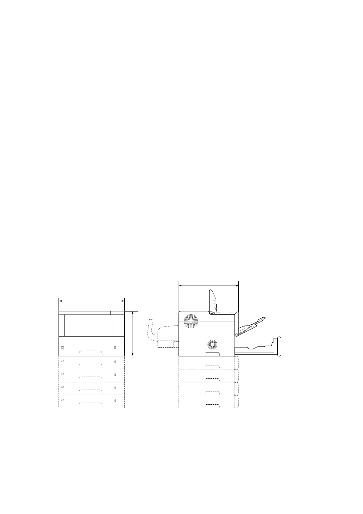
6.Allow sufficient access for proper operation and maintenance of the machine.
Machine front: 1000 mm/39
Machine right: 700 mm/27
220 - 240 V AC, 7.2 A (European countries)
3
/8" Machine rear: 100 mm/315/16"
1
/2" Machine left: 600 mm/235/8"
FS-6020
c
a
b
a: 467 mm/183/8"
b: 310 mm/12
c: 410 mm/16
3
1
/16"
/8"
Figure 1-2-1 Installation dimensions
1-2-1
Page 22

FS-6020
This page is intentionally left blank.
1-2-2
Page 23
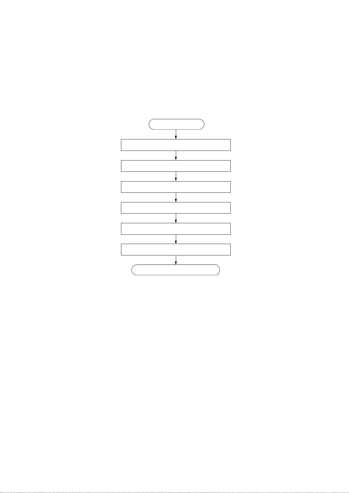
1-3-1 Unpacking and installation
(1) Installation procedure
FS-6020
Start
Unpacking.
Installing the toner container.
Connecting the printer cable.
Connecting the power cord.
Loading paper.
Printing a status page for test.
Completion of the machine installation.
1-3-1
Page 24
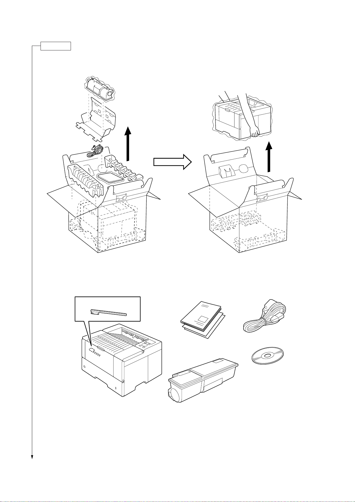
FS-6020
Unpacking.
Unpack as shown in the figure below.
Separation charger
cleaning brush
Printer FS-6020
Figure 1-3-1 Unpacking
Power cord
Operation Guide
Kyocera Mita
digital library
CD-ROM
Toner container TK-400
Figure 1-3-2 Shipped components
1-3-2
Page 25
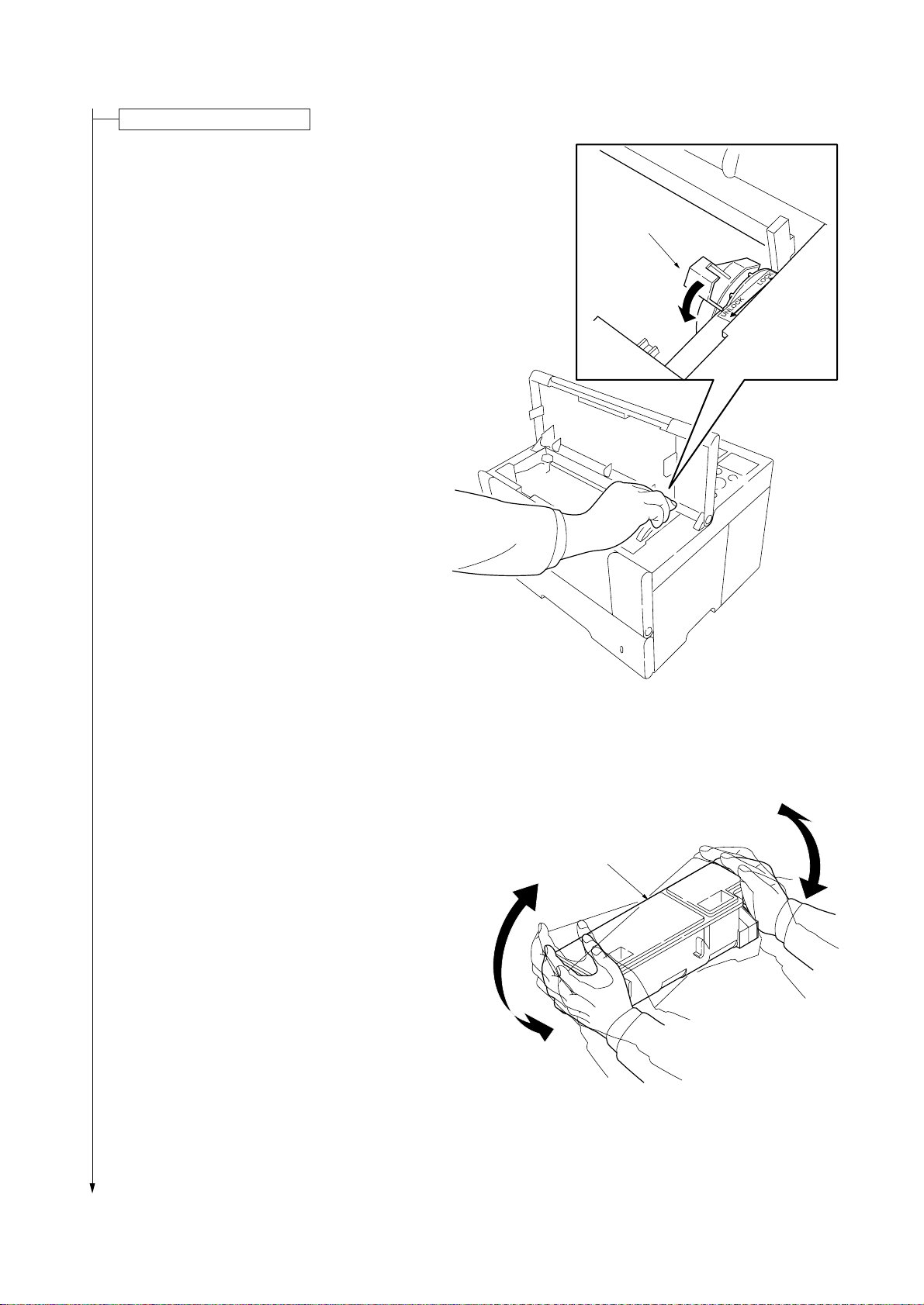
Installing the toner container.
1.Open the top cover.
2.Turn the lock lever to the UNLOCK position.
(LOCK position at shipping)
FS-6020
Lock lever
3.Shake the toner container more than ten times to
loosen the toner.
Figure 1-3-3
Toner container
Figure 1-3-4
1-3-3
Page 26
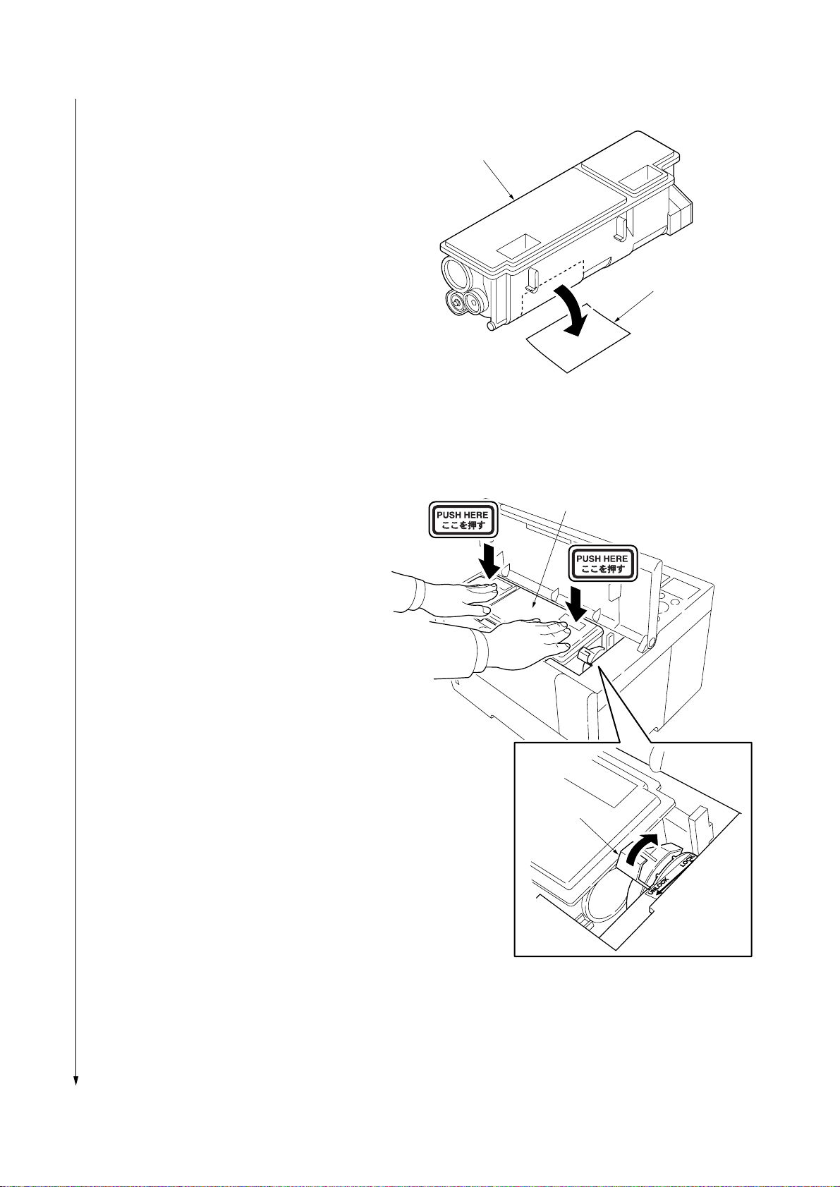
FS-6020
4. Remove the protective seal from the toner
container.
5. Install the toner container into the printer.
6. Push the upper part of the toner container on
which “PUSH HERE” is printed until the container
clicks.
7. Turn the lock lever to the LOCK position.
8. Close the top cover.
Toner container
Protective seal
Figure 1-3-5
Toner container
1-3-4
Lock lever
Figure 1-3-6
Page 27
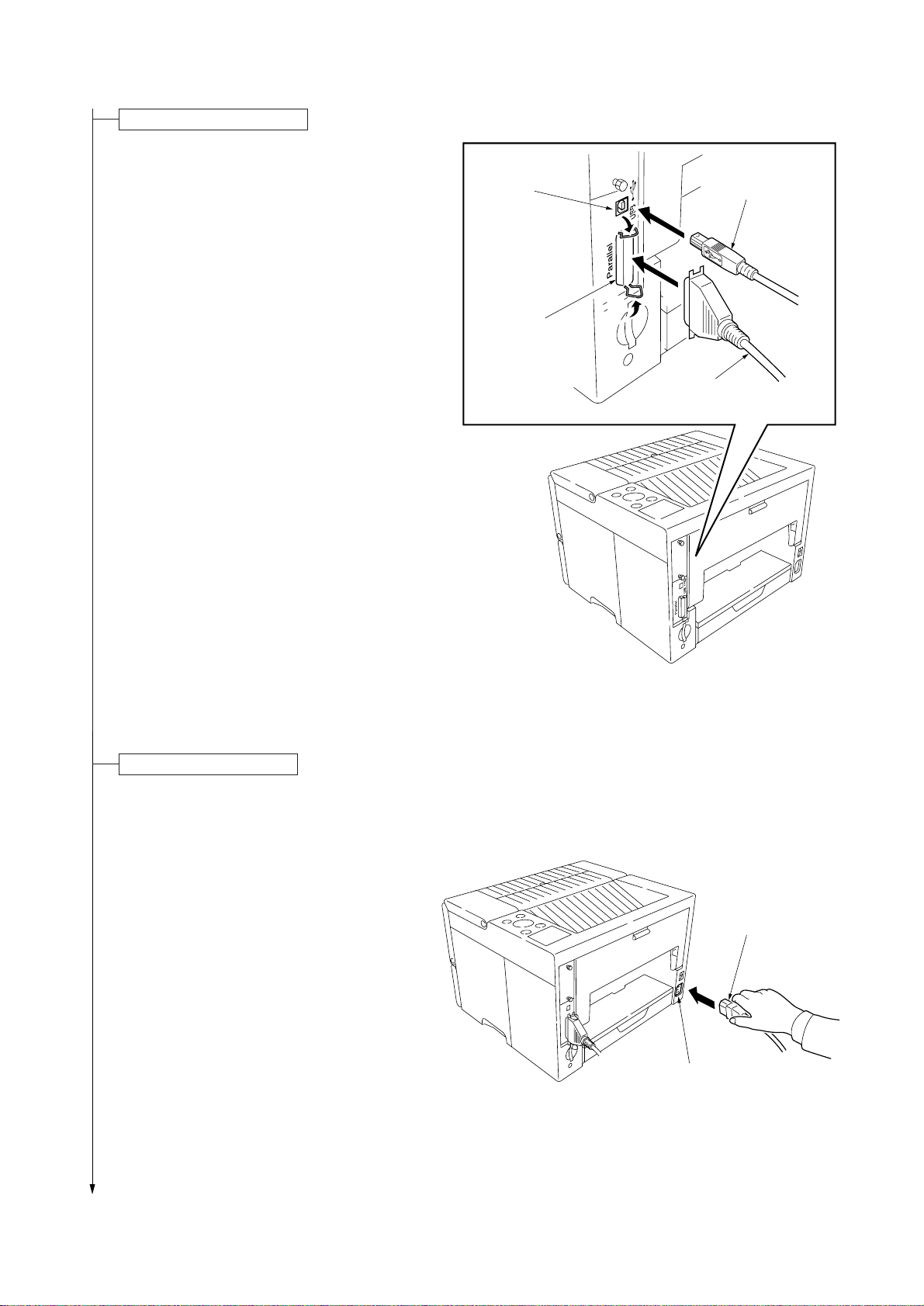
Connecting the printer cable.
For connection to a computer, parallel interface or
USB interface can be used in the standard
configuration. If an optional network interface card
or serial interface card is installed, network
connection or serial interface connection is
available.
1.Connect the parallel interface cable or the USB
interface cable to their relevant interface
connector.
USB interface
connector
Parallel
interface
connector
2
2
FS-6020
USB interface
cable
1
Parallel interface
cable
Connecting the power cord.
1. Connect the power cord to the AC inlet.
Figure 1-3-7
Power cord
AC inlet
Figure 1-3-8
1-3-5
Page 28
FS-6020
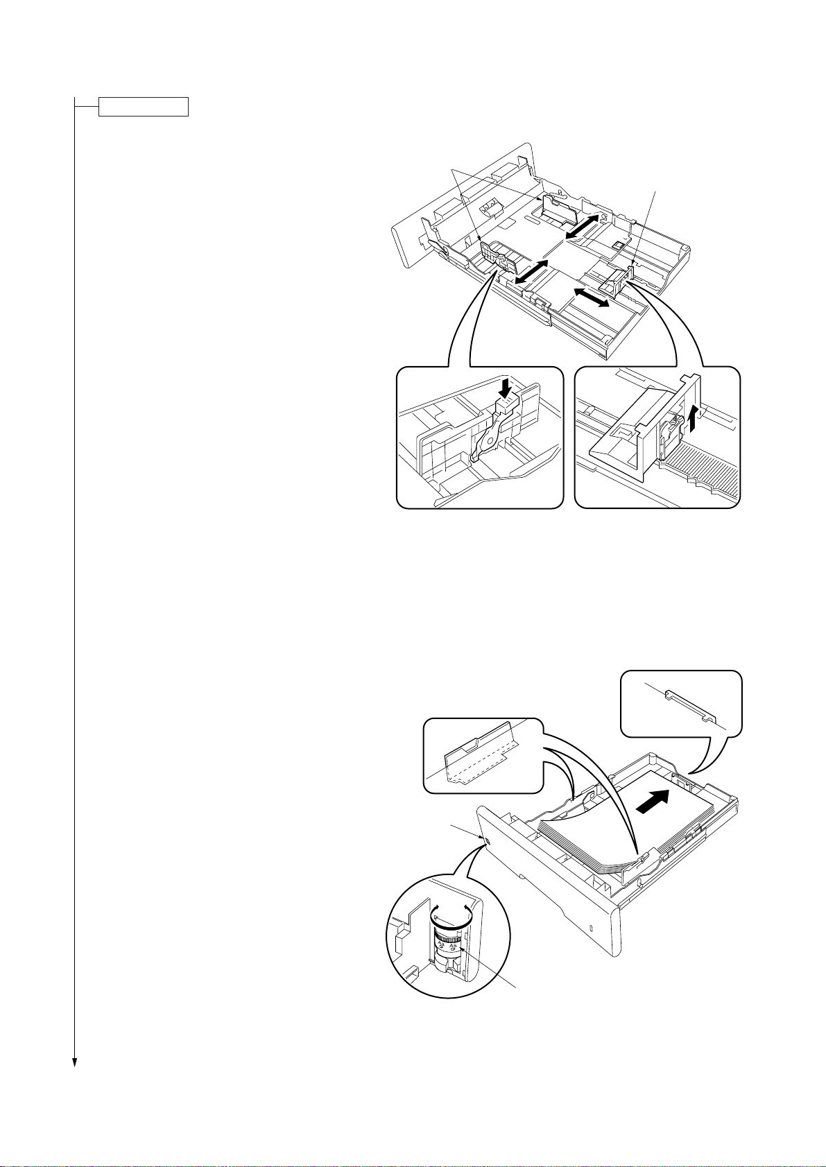
Loading paper.
1. Remove the cassette from the printer.
2. Adjust the paper guides and the paper stopper
according to the paper size to be used.
3. Set the stack of paper that does not exceed the
paper upper limit marks on the paper guides and
the paper stopper by aligning the top of the stack
and placing the rear side first. (Approximate 250
sheets of 0.1 mm thick paper can be loaded.)
Paper guides
Paper stopper
4. Turn the paper size dial so that the size of the
loaded paper is indicated in the paper size
indication window.
If “OTHER” is selected, paper size setting must
be performed on the operation panel of the
printer.
5. Install the cassette into the printer.
Figure 1-3-9
Paper size
indication
window
1-3-6
Paper size dial
Figure 1-3-10
Page 29

Printing a status page for test.
1.Turn on the printer power switch. Initialization of
the machine will start. The message will change
from “Self test” to “Please Wait Adding
toner” and then change to “Ready” when
initialization is complete (after approximately 15
minutes).
2.Use the following key operation to print a status
page for test.
1 Press the MENU key when “Ready” is
displayed.
2 Press the N key to display “Print Status
Page”.
3 Press the ENTER key to display “Print
Status Page?”.
4 Press the ENTER key. “Processing” will be
displayed and status page printing will start.
When printing is complete, “Ready” will appear
again.
3.Check to see if the printout of the status page is
proper.
FS-6020
Completion of the machine installation.
1-3-7
Page 30
FS-6020
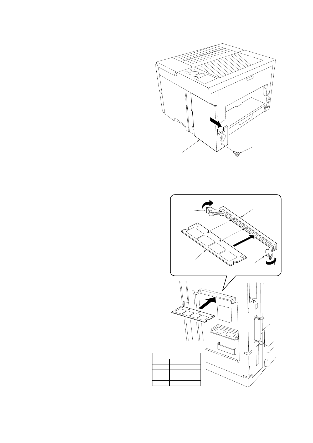
1-3-2 Installing expansion memory (optional)
Procedure
1. Turn off the printer power switch.
Cautions
Do not insert or remove expansion memory
while the printer power is on. Doing so may
cause damage to the printer or the expansion
memory.
2. Remove one screw and then remove the
optional interface slot cover.
3. Open the stoppers of the memory socket.
Screw
Optional interface
slot cover
Figure 1-3-11
4. Insert the memory so that the two notches of
the memory are engaged with the projections
of the memory socket.
* Memory produced by Melco Inc. of which
the operation has been confirmed is
recommended.
5. Close the stoppers of the memory socket.
6. Reattach the optional interface slot cover to
its original position.
7. Print a status page to check the memory
expansion.
* If memory expansion has been properly
performed, information on the installed
memory is printed and the total memory
capacity has been increased.
(Memory capacity at shipping is 16 MB.)
Stopper
Memory
Recommended memory
(Operation has been checked.)
Produced by Melco Inc.
Capacity
16 MB
32 MB
64 MB
128 MB
Part number
PM-HP-16M-KC
PM-HP-32M-KC
PM-HP-64M-KC
PM-HP-128M-KC
Memory socket
Stopper
1-3-8
Figure 1-3-12
Page 31

1-3-3 Installing network interface card (optional)
Procedure
1. Remove the two screws and then remove the
optional interface slot cover.
2. Insert the network interface card into the
optional interface slot.
3. Use the two screws to secure the network
interface card.
Cover
Optional interface slot
Network
interface
card
FS-6020
IB-22
Screws
4. Connect the network cable (in the case of IB20 or IB-21E).
5. Perform the network setting. (See IB-2x quick
configuration guide.)
Setting items for wireless network interface card IB-22
Variable name Setting range
Wireless LAN Mode
SSID
Channel
Encryption(WEP)
WEP key
Ad hoc/802.11 Ad hoc/
Infrastruccture/Automatic
Any string (up to 32 characters)
Depends on the setting range
available for the wireless NIC.
DISABLE/64 bit/128 bit
Hexadecimal setting (00-FF)
64 bits = 10 digits
128 bits = 26 digits
Screws
Network interface card that can be installed
Part number Specifications Remarks
IB-20 10 Base-TX,100 Base-TX,10 Base2
IB-21E 10 Base-TX,100 Base-TX
IB-22 Compatible to IEEE 802.11b
Wireless LAN
Figure 1-3-13
Network interface
card
Network cable
Figure 1-3-14
1-3-9
Page 32

FS-6020
1-3-4 Installing hard disk unit (optional)
Procedure
1. Remove one screw and then remove the
optional interface slot cover.
Screw
Optional interface
slot cover
2. Insert the hard disk unit into the hard disk
socket.
3. Reattach the optional interface slot cover to
its original position.
4. Format the hard disk. (Refer to the operation
guide.)
Hard disk unit
Figure 1-3-15
Hard disk socket
Hard disk units that can be installed
(Microdrive)
Manufactured by IBM
Capacity
340 MB
512 MB
1 GB
Model number
DMDM-10340
DSCM-10512
DSCM-11000
1-3-10
Figure 1-3-16
Page 33

1-3-5 Installing memory card (optional)
Procedure
1. Turn off the printer power switch.
Cautions
Do not insert or remove a memory card
while the printer power is on. Doing so may
cause damage to the printer or the memory
card.
2. Insert the memory card into the memory card
slot.
* A memory card of which the operation has
been confirmed is recommended. (Refer to
the CF guideline.)
3. Format the memory card. (Refer to the
operation guide.)
FS-6020
Memory card slot
Memory card
Figure 1-3-17
1-3-11
Page 34

FS-6020
This page is intentionally left blank.
1-3-12
Page 35

FS-6020
1-4-1 Service mode
The printer is equipped with various service modes that can be accessed with MENU key operation on the operation
panel.
(1) Executing service mode
Message display
Ready
--- A4 PLAIN
1 Press the MENU key.
Print
Menu Map
2 Press the M or N key several times
until “Other >” is displayed.
Other >
Service mode items
>>Print
Status Page
>>Eraser
>>Print
Event Log
>>Developer
>MSG Language
English
3 Press the ENTER key.
>Service >
4 Press the M or N key several times
until “>Service >” is displayed.
5 Press the key.
To print a status page for service purchase.
See page 1-4-2.
To print a test pattern for detecting eraser lamp disconnection.
See page 1-4-5.
To print an event log (EVENT LOG).
(*Displayed when the set value of FRPO Ι1 is 1.)
See page 1-4-6.
To perform initialization after replacing the process unit.
See page 1-4-9.
>>Drum
To perform drum surface refreshing.
See page 1-4-9.
1-4-1
Page 36

FS-6020
Service items Description
Printing a status page for service purpose
>>Print
Status Page
Description
Prints a status page for service purpose. The status page includes various printer settings
and service data.
Purpose
To acquire printer setting environment and service data information.
Procedure
1. Enter the service mode [>>Print Status Page].
2. Press the ENTER key. “Print Status Page?” will be displayed.
3. Press the ENTER key. Two status pages will be printed. (The second status page includes
service information.)
Service information
(See the next page.)
Main PWB firmware version
Firmware version: 91.01
Firmware version: 91.01
Service Information
[0104/0086][C2][34.00EFLB][03/03] Total page 9690
/t/P00/S00/F00/N00/D20:lotte
/0020/0020/1061/0811/ 0/ 0/ 0/ 0/ 0/ 0/ 0/
/AAAAAAA/AAAAAAA/
/AAAAAAA/AAAAAAA/AAAAAAA/AAAAAAA/AAAAAAA/AAAAAAA/
/AAAAAAA/AAAAAAA/AAAAAAA/AAAAAAA/AAAAAAA/AAAAAAA/
/AAAAAAA/AAAAAAA/AAAAAAA/
/AAAAAAA/
/0000/0000/0000/0000/0000/
/RS2/FF/[0003-0003]/AI.E/81/06
/8088808880808000/8088808880808000/8088808880808000/8088808880808000
/00800080/00008000/00000080/80000000/00000000/00000000/00000000/
/03030303/03030303/03030303/03000000/00000000/03030303/03030303/
SPD1:0203040508090A0B0C0D0F101112131415161718191A1B1C1D1E1F202122235E
SN:SPL9200010
Released date of the firmware
Released: 10/Sep/2002
Released: 10/Sep/2002
1-4-2
Fig. 1-4-1 Status page for service
Page 37

FS-6020
Service items Description
Details of service information
Service information
[0104/0086][C2][34.00EFLB][03/03] Total page 9690
123 4
/t/P00/S00/F00/N00/D20:lotte
6
7890 !
/0020/0020/1061/0811/ 0/ 0/ 0/ 0/ 0/ 0/ 0/
@
#
/AAAAAAA/AAAAAAA/
$
/AAAAAAA/AAAAAAA/AAAAAAA/AAAAAAA/AAAAAAA/AAAAAAA/
%
/AAAAAAA/AAAAAAA/AAAAAAA/AAAAAAA/AAAAAAA/AAAAAAA/
^
/AAAAAAA/AAAAAAA/AAAAAAA/
&
/AAAAAAA/
*
/0000/0000/0000/0000/0000/
(
5
/RS2/FF/[0003-0003]/AI.E/81/06
)⁄
¤‹›fi
/8088808880808000/8088808880808000/8088808880808000/8088808880808000
fl
/00800080/00008000/00000080/80000000/00000000/00000000/00000000/
‡
/03030303/03030303/03030303/03000000/00000000/03030303/03030303/
°
SPD1:0203040508090A0B0C0D0F101112131415161718191A1B1C1D1E1F202122235E
·
SN:SPL9200010
‚
Table 1-4-1 Details of service information
Item Description
1 Engine ROM information
2 Operation panel information
3 Boot ROM information
[Mask ROM version/flash ROM version]
[Operation panel mask version]
[Boot ROM version]
Upper 6 digits: Boot ROM version
Lower 3 digits: Flash DIMM type
MXI: Macronix
FUB: Fujitsu (bottom type)
FUT: Fujitsu (top type)
FLB: Fujitsu (29LV160B)
FLT: Fujitsu (29LV160T)
HUB: Hyundai (bottom type)
HUT: Hyundai (top type)
---: Other manufacturers
***: Mask DIMM
1-4-3
Page 38

FS-6020
Service items Description
Item Description
4 Software jumper switch information
(hexadecimal)
5 Total page
6 Toner installation information (displayed
only when the mode is set)
7 Parallel I/O information
8 Serial I/O error code (Not supported by this
machine)
9 Operation panel lock status (displayed only
when locked)
0 NVRAM error (displayed only when any
error has occurred)
! NVRAM downloading status
@ Printable area setting
# Left offset for each paper source
$ Page counter according to paper size
% Page counter according to paper feeder (2
or 3)
^ Page counter according to paper feeder (4
or 5)
[First byte/second byte (displayed in OEM mode only)]
First byte
Bit 0 = 1: (Fixed)
Bit 1 = 0: Overseas; 1: Domestic (Japan)
Bit 2, 3 (Not used)
Bit 4 = 0: Kyocera; 1: OEM
Bit 5 = 0: For Europe; 1: For US
Bit 6 = 0: Non MICR mode; 1: MICR mode
Bit 7 = 0: Kyocera; 1: Kyocera Mita
Second byte: Displayed in OEM mode only.
Total print page count
(Toner installation mode display) Standby mode
(After prescribe command TNRE “INST” is entered, until the
power is turned off)
00: Normal
Bit 0: Framing error
Bit 1: Overrun error
Bit 2: Parity error
01: Partial lock
02: Full lock
01: ID error
02: Version error
03: Checksum error
04: NVRAM crash error
00: Normal (not downloaded)
Bit 0: Font data
Bit 1: Host data
Bit 2: Macro data
Bit 3: Program data
Bit 4: Operation panel message data (file name displayed)
Bit 5: OEM data (file name displayed)
Bit 6: Reserved
Bit 7: Error occurred
/Top offset/Left offset/Page length/Page width
/MP tray/Cassette 1/Cassette 2/Cassette 3/Cassette 4
/Cassette 4/Duplexer
/Legal/Small/
“Small” means sizes smaller than legal and that can be fed.
/Feeder 2 (total)/Feeder 2 (small)/Feeder 2 (large)
/Feeder 3 (total)/Feeder 3 (small)/Feeder 3 (large)
* “Total” is calculated by adding the number for “small” to 2 ×
number for “large” (double count).
* “Small” means sizes of which the length in the sub-scan
direction is less than 335 mm (length of legal size), and
“large” means sizes of which the length is 335 mm or more.
/Feeder 4 (total)/Feeder 4 (small)/Feeder 4 (large)/Feeder 5
(total)/Feeder 5 (small)/Feeder 5 (large)
* “Total” is calculated by adding the number for “small” to 2 ×
number for “large” (double count).
* “Small” means sizes of which the length in the sub-scan
direction is less than 335 mm (length of legal size), and
“large” means sizes of which the length is 335 mm or more.
1-4-4
Page 39

Service items Description
Item Description
FS-6020
& Duplexer life counter
* Maintenance kit counter
( Optional unit version
) Serial interface information
⁄ Drum sensitivity information
¤ Optional unit information
‹ Average printing ratio (2 digits for integer
part, 1 digit for decimal part)
› Operation panel message language
fi Toner capacity setting
fl Engine parameter setting
‡ Media type attributes
— Media type attributes
· Memory SPD information (slot 1)
‚ Machine serial number
/Duplexer (total)/Duplexer (small)/Duplex er (large)/
* “Total” is calculated by adding the number for “small” to 2 ×
number for “large” (double count).
* “Small” means sizes of which the length in the sub-scan
direction is less than 335 mm (length of legal size), and
“large” means sizes of which the length is 335 mm or more.
/Feeder 2/Feeder 3/Feeder 4/Feeder 4/Duplexer/
RS2: RS-232C RS4: RS-422A
Upper 2 bytes
Bit 0: MPF
Bits 1 to 6: Feeders 1 to 6 (6 is not supported)
Bit 7: Duplexer
Bits 8 to 15: Reserved
Lower 2 bytes
Bit 0:
Bit 1: Face-up (not supported)
Bits 2 to 15: Reserved
Printing ratio for the total period from shipping
(displayed in %)
PMSG command setting (decimal)
Decimal (× 100 sheets)
Hexadecimal, 32 bytes (64 digits)
Media type setting value from 1 to 28 (fixing temperature,
paper thickness, duplex printing)
(14 to 20 are unused and always 0x00.)
Media type setting value from 1 to 28 (print density)
(14 to 20 are unused and always 0x00.)
Bus error if all digits are “E”.
-
1-4-5
Page 40

FS-6020
Service items Description
Printing a test pattern for detecting eraser lamp disconnection
>>Eraser
Description
Prints a page that includes a test pattern (black bar with approximately 1 cm width) using
high voltage output control of engine/high voltage PWB. If the eraser operates normally, the
black bar is printed. If the eraser does not operate normally, the bar is not printed.
Purpose
To check for disconnection based on printing of the black bar. The conventional selfdiagnostic function does not check the eraser lamp disconnection error (error code 5300
[E5]).
Procedure
1. Load paper into the paper cassette.
2. Enter the service mode [>>Eraser].
3. Press the ENTER key. Message “>>Eraser ?” will be displayed.
4. Press the ENTER key.
5. A status page or a menu map will be printed. If the eraser lamp is normal, a page
including a test pattern (black bar with approximately 1 cm width) is printed.
Approximately
1 cm
Black bar
Paper
Fig. 1-4-2 Test pattern for detecting eraser lamp disconnection
1-4-6
Page 41

Service items Description
[0114][C2][37.00HFLB][03]
SN:SPL2700012
Firmware version: 91.01
7 519 02.11.48.02.09.01.88.21.73.FA.A8.C0
Paper jam/Printer unit
6 515 02.11.48.01.09.01.88.11.73.FA.A8.C0
Paper jam/Printer unit
5 166 02.11.48.01.09.01.88.11.73.FA.A8.C0
Paper jam/Printer unit
4 71 02.11.48.02.09.01.88.21.73.FA.A8.C0
Paper jam/Printer unit
3 71 02.11.48.01.09.01.88.11.73.FA.A8.C0
Paper jam/Printer unit
2 64 02.11.32.01.91.00.88.32.74.04.A8.C0
Paper jam/Cassette 2
1 57 02.11.32.01.91.00.88.32.74.04.A8.C0
Paper jam/Cassette 2
Released: 10/Sep/2002
Number Page Count Code
Event list
Total page 522
Printing an event log (EVENT LOG)
>>Print
Event Log
Description
Prints the history of paper misfeeds and self-diagnostic errors including up to 16 items from
the latest item. (If the number of errors exceeds 16, errors will be deleted sequentially from
the oldest one.)
Purpose
To allow machine malfunction analysis based on the frequency of paper misfeeds and selfdiagnostic errors.
Procedure
1. Enter the service mode [>>Print Event log].
2. Press the ENTER key. “>>Print Event Log?” will be displayed.
3. Press the ENTER key. A sheet of event log will be printed.
FS-6020
Fig. 1-4-3 Event log (EVENT LOG)
Details of event list
The event list includes the following information.
A Number Prints a list of error history (1 to 16). A smaller number means an older
event.
B Number of pages Number of pages printed when an error occurred
C Description Indicates the description of error.
D Code Code 1 identifies an error and codes 2 to 9 indicate the details.
The value 02 of code 1 means a paper misfeed. See code table (1).
The value 99 of code 1 means a self-diagnostic error. See code table (2).
Number Page Count Code
A B
7 519 02.11.48.02.09.01.88.21.73.FA.A8.C0
6 515 02.11.48.01.09.01.88.11.73.FA.A8.C0
5 166 02.11.48.01.09.01.88.11.73.FA.A8.C0
4 71 02.11.48.02.09.01.88.21.73.FA.A8.C0
3 71 02.11.48.01.09.01.88.11.73.FA.A8.C0
2 64 02.11.32.01.91.00.88.32.74.04.A8.C0
1 57 02.11.32.01.91.00.88.32.74.04.A8.C0
1 2 3 4 5 6 7 8
Paper jam/Printer unit
Paper jam/Printer unit
Paper jam/Printer unit
Paper jam/Printer unit
Paper jam/Printer unit
Paper jam/Cassette 2
Paper jam/Cassette 2
9-(a) 9-(b)
7 519 02.11.48.02.09.01.88.21.73.FA.A8.C0
Paper jam/Printer unit
Fig. 1-4-4 Details of event list
D
C
1-4-7
Page 42

FS-6020
Service items Description
Table 1-4-2 Code table (1)
Code digit and
description
1 Identification
code
2 Error type
(hexadecimal)
3 Paper
misfeed
location
(ASCII)
4 Paper
misfeed
sensor
location
(hexadecimal)
5 Cause of
paper
misfeed
(hexadecimal)
6 Paper
source
(hexadecimal)
7 Paper size
(hexadecimal)
Details of code
02: Paper misfeed
11: Paper misfeed
31: Cassette 1
Printer
32: Cassette 2
33: Cassette 3
34: Cassette 4
35: Cassette 5
42: MP tray
47: Rear cover
48: Inside the printer
49: Duplexer
01: Paper feed sensor [32]
Paper feed sensor [33]
Paper feed sensor [34]
Paper feed sensor [35]
Registration sensor [48]
Switchback timing
sensor [49]
02: Eject sensor [47]
Refeed rear edge
sensor [49]
03: Refeed eject sensor [49]
99: Not determined
Values within [ ] indicate paper
Duplexer
Paper feeder 1
Paper feeder 2
Paper feeder 3
Paper feeder 4
01
02
47
(Rear cover)
02
49
(Inside the printer)
48
01
03
(Cassette 1)
(Cassette 2)
(Cassette 3)
(Cassette 4)
(Cassette 5)
01
01
01
01
(MP tray)
31
32
33
34
35
misfeed locations.
01: Paper did not pass within a specified time.
02: Paper did not arrive within a specified time.
09: Paper remains longer than a specified time. (other than 01 and 02)
11: Paper misfeed occurred when paper is being transported.
91: Paper remains when power is turned on.
99: Others (Paper stopped due to external cause such as opening of a cover during
printing.)
00: MP tray 04: Cassette 4 08: Duplexer
01: Cassette 1 (in the printer) 05: Cassette 5 99: Reserved
02: Cassette 2 06: Reserved
03: Cassette 3 07: Reserved
01: Monarch 0D: A5 22: 216 × 316 (mm)
02: Business 0E: A6 24: A3 wide
03: International DL 0F: B6 25: Ledger wide
04: International CS 10: Commercial #9 27: 8K
05: Ex ecutive 11: Commercial #6 28: 16K
06: Letter size 12: ISO B5 32: Statement
07: Legal size 13: Custom size 33: Folio
08: A4 1E: C4 34: Western type 2
09: B5 1F: Postcard 35: Western type 4
0A: A3 20: Reply-paid postcard 86: Letter-R
0B: B4 21: Oficio II 88: A4-R
0C: Ledger size 22: 216 × 310 mm 89: B5-R
42
1-4-8
Page 43

Service items Description
FS-6020
Code digit and
description
8 Main cause
of paper
misfeed
(hexadecimal)
9 (a) Misfed
paper width
(hexadecimal)
(b) Misfed
paper length
(hexadecimal)
Details of code
10: Paper does not arrive at the registration sensor.
11: Paper does not pass the registration sensor.
12: Paper remains at the registration sensor when power is turned on.
20: Paper does not arrive at the eject sensor.
21: Paper does not pass the eject sensor.
22: Paper remains at the eject sensor when power is turned on.
30: Paper does not arrive at the paper feeder 1 feed sensor.
31: Paper does not pass the paper feeder 1 feed sensor.
32: Paper remains at the paper feeder 1 feed sensor when power is turned on.
40: Paper does not arrive at the paper feeder 2 feed sensor.
41: Paper does not pass the paper feeder 2 feed sensor.
42: Paper remains at the paper feeder 2 feed sensor when power is turned on.
50: Paper does not arrive at the paper feeder 3 feed sensor.
51: Paper does not pass the paper feeder 3 feed sensor.
52: Paper remains at the paper feeder 3 feed sensor when power is turned on.
60: Paper does not arrive at the paper feeder 4 feed sensor.
61: Paper does not pass the paper feeder 4 feed sensor.
62: Paper remains at the paper feeder 4 feed sensor when power is turned on.
A1: Paper does not arrive at the duplexer switchback timing sensor.
A2: Paper does not arrive at the duplexer refeed rear edge sensor.
A3: Paper does not pass the duplexer switchback timing sensor.
A4: Paper does not arrive at the duplexer refeed eject sensor.
A5: Paper does not pass the duplexer refeed rear edge sensor.
A6: Paper does not pass the duplexer refeed eject sensor.
A7: Duplexer overflow (Third sheet is commanded when second sheet remains.)
A8: Duplexer drive signal output from the printer while paper is transported turns off.
A9: Paper remains in the duplexer when power is turned on.
AA: The rear cover of the duplexer is opened while paper is transported.
B1 to B3, C1: Reserved
E0: Paper misfeed occurs due to forced stop when an error occurs during printing. (such
as opening of a cover)
F0 to FF: Paper misfeed by another cause
0000 to FFFF [in 0.1 mm]
Example: 73FA (hexadecimal) = 29690 (decimal) = 296.9 mm
0000 to FFFF [in 0.1 mm]
Example: A8C0 (hexadecimal) = 43200 (decimal) = 432.0 mm
1-4-9
Page 44

FS-6020
Service items Description
Table 1-4-3 Code table (2)
Code digit and
description
1 Identification
code
(hexadecimal)
2 Self-
diagnostic
error code
[Upper digit
of former 2
digits]
(hexadecimal)
3 Self-
diagnostic
error code
[Lower digit
of former 2
digits]
(hexadecimal)
4 to 8
(Remarks) Self-diagnostic error codes E0 and F0 to F2 are not recorded.
99: Self-diagnostic error
10: A
11: B
12: C
13: D
14: E
00: 0 06: 6 12: C
01: 1 07: 7 13: D
02: 2 08: 8 14: E
03: 3 09: 9 15: F
04: 4 10: A
05: 5 11: B
Unused
Details of code
>>Developer
>>Drum
Initialization after replacing the process unit (toner installation mode)
Description
Replenishes toner rapidly from the toner container into the process unit.
Purpose
To execute after replacing the process unit to replenish toner rapidly into the process unit that
includes no toner.
Procedure
1. Enter the service mode [>>Developer].
2. Press the ENTER key. Message “>>Developer?” will be displayed.
3. Press the ENTER key. Message “Ready” will be displayed.
4. Turn off and then on the printer. The toner installation mode will start after warm-up is
complete, and “Please Wait Adding toner” will be displayed during this operation.
The operation will be complete after approximately 15 minutes.
* To cancel this mode, use the following procedure instead of turning on the power while
pressing all cassette size switches like in the former models. Turn off and then on the
printer to restart the printer. Enter the service mode [>>Developer] during warm-up. Run
this mode again. Then this mode will be canceled.
Drum surface refreshing
Description
Rotates the drum approximately 5 minutes with toner lightly on the overall drum using the
high-voltage output control of the engine/high voltage PWB. The cleaning blade in the
process unit scrapes toner off the drum surface to clean it.
Purpose
To clean the drum surface when image failure occurs due to the drum. This mode is effective
when dew condensation on the drum occurs.
Procedure
1. Enter the service mode [>>Drum].
2. Press the ENTER key. Message “>>Drum?” will be displayed.
3. Press the ENTER key. Drum surface refreshing will start and finish after approximately 3
minutes.
1-4-10
Page 45

FS-6020
1-5-1 Paper misfeed detection
(1) Paper misfeed indication
When a paper misfeed occurs, the printer immediately stops printing and displays the paper misfeed message on the
operation panel. To remove paper misfed in the printer, open the front cover or the rear cover or pull out the paper cassette.
7
8
Paper misfeed location
Figure 1-5-1 Paper misfeed message display
2
Paper Jam
MP tray
9
6
6
6
1
5
5
5
Paper misfeed message
4
3
Printer
1 Registration sensor
2 Face-down tray paper full sensor
3 Paper gauge sensor
4 MP tray paper feed sensor
Paper feeder (optional)
5 Paper feed sensor
6 Paper gauge sensor
Duplexer (optional)
7 Switchback timing sensor
8 Refeed rear edge sensor
9 Refeed paper eject sensor
5
6
Figure 1-5-2 Paper misfeed detection
1-5-1
Page 46

FS-6020
1-5-2 Self-diagnosis
(1) Self-diagnostic function
This printer is equipped with a self-diagnostic function. When a problem is detected, the printer stops printing and an error
message is displayed on the operation panel. An error message consists of a message prompting contact to service
personnel, total print count, and a four-digit error code (2 digits for F0 only) indicating the type of the error. (The display varies
a little with the type of the error.)
Error codes 2000 to 6040
Call service
2000:0123456
Error codes F010 to F080
Call service
F010
Error code F0
Call service
person F0
Figure 1-5-3 Error message display
Error code
Error code
Error code
1-5-2
Page 47

FS-6020
(1-1) Error code 2000 [E1] (main motor error)
Detection conditions
• The main motor ready signal (MOTRDYN) does not become ready (low level) a specified time after the main motor drive
signal (MOTONN) is turned on.
• The main motor ready signal (MOTRDYN) does not become ready (low level) a specified time after the main motor drive
signal (MOTONN) is turned off.
Corrective measures
Start
Is there any damage to
the harness (S02814) between
the engine/high voltage PWB and the
main motor or improper connection at the
YC12 connector on the
engine/high-voltage
PWB?
Yes
* Possible defective locations
(causes)
• Engine/high voltage PWB
• Fixing unit
• Power source PWB
• Large load applied to
the main motor
No
If any problem is found on the
harness or the connector,
repair or replace it.
Turn on the printer, connect a tester
or an oscilloscope, and measure as
follows.
Is the voltage at
pin No. 1 (+24V3) of
the main motor connector DC
24 V in the printer
standby mode?
Yes
Print a status page.
Does the level at
pin No. 3 (MOTONN) of
the main motor connector change
from H to L in synchronization
with activation of the
motor?
No
No
OK?
End
Yes
No
Print a status page.
Does the level at pin
No. 4 (MOTRDYN) of the
main motor connector change from H to
L after activation of the motor
(after approximately 2
seconds)?
Yes
Replace the engine/high voltage
PWB. (See page 1-6-26.)
No
Replace the main motor.
Yes
Replace the engine/high voltage
PWB. (See page 1-6-26.)
OK?
End
No
Yes
Replace the main motor and the
engine/high voltage PWB at the
same time. (See page 1-6-26.)
1-5-3
Page 48

FS-6020
(1-2) Error code 4000 [E2] (polygon motor error)
Detection conditions
• The polygon motor ready signal (MOTRDYN) does not become ready (L level) within a specified time after the polygon
motor drive signal (POLONN) is turned on (L level).
Corrective measures
Start
Is there any
damage to the harness
(S02819) between the main PWB
and the laser scanner unit or improper
connection at the YC8
connector on the main
PWB?
Turn on the printer, connect a tester
or an oscilloscope, and measure as
follows.
* Possible defective locations
(causes)
• Laser scanner unit
• Engine/high voltage PWB
• Harness (S02819)
• Main PWB
Yes
If any problem is found, repair
or replace it.
No
Print a status page.
Does the level
at pin No. 3
(POLONN) of the main PWB
connector YC8 change
from H to L?
Yes
Print a status page.
Replace the engine/high
voltage PWB. (See page 16-26.) If the error is not
cleared, replace the main
PWB. (See page 1-6-25.)
No
Is the voltage
at pin No. 5
(+24V3) of the main PWB
connector YC8 24
V DC?
Yes
Replace the engine/high
voltage PWB. (See page 16-26.) If the error is not
cleared, replace the main
PWB. (See page 1-6-25.)
Is the
frequency at pin No. 1
(POLCLK) of the main PWB
connector YC8 2.2
KHz?
Yes
Replace the engine/high
voltage PWB. (See page 16-26.) If the error is not
cleared, replace the main
PWB. (See page 1-6-25.)
No
No
Does the level
at pin No. 2
(POLRDYN) of the main PWB
connector YC8 change
from H to L?
Yes
Replace the laser scanner
unit. (See page 1-6-15.)
Replace the engine/high
voltage PWB. (See page 16-26.) If the error is not
cleared, replace the main
PWB. (See page 1-6-25.)
No
OK?
Yes
Replace the laser scanner
unit. (See page 1-6-15.) If the
error is not cleared, replace
the laser scanner unit and the
engine/high voltage PWB at
the same time.
No
1-5-4
End
Page 49

FS-6020
(1-3) Error code 4200 [E3] (laser output error)
Detection conditions
• The pin photo signal (PDN) is not output within a specified time after the polygon motor ready signal (MOTRDYN)
becomes ready (L level).
Corrective measures
Start
Is there any damage
to the harness (S02820)
between the main PWB and the PD
PWB or improper connection at the
YC11 connector on the main
PWB?
Yes
Turn on the printer, connect a tester
or an oscilloscope, and measure as
follows.
* Possible defective locations
(causes)
• Main PWB
• Laser scanner unit
No
If any problem is found on the
harness or the connector,
repair or replace it.
No
OK?
Yes
Replace the laser scanner
unit. (See page 1-6-15.)
End
Is the voltage at
the following pins of the
main PWB 5 V DC in the printer
standby mode?
Pin No. 6 of the YC10 connector
Pin No. 1 of the YC11
connector
Yes
Replace the laser scanner
unit. (See page 1-6-15.)
No
OK?
Yes
End
Replace the laser scanner unit
and the main PWB at the same
time. (See pages 1-6-15 and
25.) If the error is not cleared,
replace the engine/high voltage
PWB. (See page 1-6-26.)
No
Replace the main PWB. (See
page 1-6-25.)
No
OK?
Yes
Replace the laser scanner
unit. (See page 1-6-15.)
End
1-5-5
Page 50

FS-6020
(1-4) Error code 6000 [E4] (fixing heater lamp/fixing thermistor error)
Detection conditions
• The fixing thermistor disconnection detection circuit in the engine/high voltage PWB outputs the disconnection detection
signal (THDEAD) to the CPU more than a specified time after power is turned on.
• The fixing temperature does not rise at least 1 °C when the fixing heater lamp is continuously on for approximately 20
seconds during printer warm-up or in the standby mode.
• The fixing temperature does not rise at least 1 °Cwhen the fixing heater lamp is continuously on for approximately 15
seconds during printing.
• The fixing temperature does not lower when the fixing heater lamp is off for a specified time or more.
* The fixing temperature is the average value calculated using the input voltage from the fixing thermistor detected several
times in a specified time to avoid influence of noise and so on.
Corrective measures
Cautions
Be careful when handling the fixing unit because it is hot.
Take care not to get an electric shock because AC power is supplied from the power source PWB to the fixing unit.
Start
* Possible defective locations
(causes)
• Engine/high voltage PWB
• Fixing unit
• Power source PWB
Does the error
occur several seconds
after the message “Please
Wait” is displayed?
Yes
Is there any damage to
the harness (S028??) between
the fixing unit and the engine/high voltage
PWB or improper connection at the YC5
connector on the engine/high-
voltage PWB?
Yes
Remove the YC5 connector from the
engine/high-voltage PWB and measure the
resistance between the pins (fixing thermistor).
Is the resistance
∞?(See the remarks.)
Yes
No
If any problem is found on the
harness or the connector,
repair or replace it.
No
Replace the engine/high voltage
PWB. (See page 1-6-26.)
No
Is there any damage to
the harness (S02823) between
the fixing unit and the power supply PWB or
improper connection at the CN2
connector on the power
supply PWB?
If any problem is found on the
Yes
harness or the connector,
repair or replace it.
Remove the CN2 connector from the
power supply PWB and measure the
resistance between the pins.
Is the
resistance ∞?
No
Yes
Replace the power supply
PWB. (See page 1-6-29.)
No
Replace the fixing unit (fixing thermistor).
(See pages 1-6-18 and 23.)
Remarks
The resistance depends on the ambient temperature of
the fixing thermistor. The relation between the ambient
temperature and the resistance is shown below.
Ambient temperature
0 °C Approx. 980 kΩ
10 °C Approx. 650 kΩ
25 °C Approx. 360 kΩ
Resistance
1-5-6
Replace the fixing unit (fixing heater
lamp). (See pages 1-6-19.)
Replace the engine/high voltage
PWB. (See page 1-6-26.)
OK?
End
No
Yes
Page 51

FS-6020
(1-5) Error code 6020 [A2] (abnormally high fixing temperature error)
Detection conditions
• The fixing heater lamp runaway protection circuit in the engine/high voltage PWB outputs continuously the abnormally
high temperature detection signal (HTEMPN) to the CPU for a longer time than specified.
Corrective measures
Cautions
Be careful when handling the fixing unit because it is hot.
Take care not to get an electric shock because AC power is supplied from the power source PWB to the
fixing unit.
Start
Is there any damage to
the harness (S028??) between
the fixing unit and the engine/high voltage
PWB or improper connection at the YC5
connector on the engine/high-
voltage PWB?
* Possible defective locations
(causes)
• Engine/high voltage PWB
• Fixing unit
• Power source PWB
No
If any problem is found on the
Yes
harness or the connector,
repair or replace it.
Turn on the printer, connect a tester
or an oscilloscope, and measure as
follows.
Is the voltage at pin
No. 1 of the YC5 connector
on the engine/high voltage PWB
higher than 3.2 V DC for more than
3 seconds when the
error occurs?
Yes
Replace the fixing unit (fixing thermistor).
(See pages 1-6-18 and 23.)
OK?
Replace the engine/high voltage
PWB. (See page 1-6-26.)
No
No
End
Yes
Replace the engine/high voltage
PWB or the power supply PWB
(See page 1-6-26 and 29.)
1-5-7
Page 52

FS-6020
(1-6) Error code 6400 [A0] (fixing heater lamp control zero-cross signal detection error)
Detection conditions
• The zero-cross signal (ZCROSS) that is output from the power source PWB and input to the CPU on the engine/high
voltage PWB is not input for a specified time.
Corrective measures
* Possible defective locations
(causes)
• Engine/high voltage PWB
• Power source PWB
• Replace either or both of the power source PWB and the engine/high voltage PWB. (See pages 1-6-29 and 26.)
(1-7) Error code F0 [F0] (communication error between the operation panel PWB and main PWB)
Detection conditions
• Serial communication between the operation panel PWB and the main PWB malfunctions.
Corrective measures
Start
Is there any damage to
the harness (S02812) between
the main PWB and the operation panel
PWB or improper connection at the YC1
connector on the operation
panel PWB?
Yes
Replace the main PWB. (See
page 1-6-25.)
* Possible defective locations
(causes)
• Main PWB
• Operation panel PWB
No
If any problem is found on the
harness or the connector,
repair or replace it.
OK?
End
No
Yes
Replace the main PWB. (See
page 1-6-25.)
1-5-8
OK?
No
Yes
Replace the operation panel PWB.
End
Page 53

(1-8) Error code F010 [F1] (code ROM checksum error)
Detection conditions
• Checksum of the code ROM PWB attached to the socket (YS1) on the main PWB malfunctions.
Corrective measures
FS-6020
Start
Is the code
ROM on the main
PWB inserted properly
into the socket?
Yes
Replace the code ROM PWB.
No
OK?
Yes
* Possible defective locations
(causes)
• Code ROM PWB
• Main PWB
No
Reattach the code ROM PWB
properly to the socket.
Replace the main PWB. (See
page 1-6-25.)
End
1-5-9
Page 54

FS-6020
(1-9) Error code F020 [F2] (main PWB RAM checksum error)
Detection conditions
Checksum in the standard RAM mounted on the main PWB or in optional expansion memory is not correct.
Corrective measures
Start
Is expansion
memory added?
O[i
Replace the main PWB. (See
page 1-6-25.)
* Possible defective locations
(causes)
• Main PWB
• Optional memory
De
Remove the expansion
memory and turn on the power.
(See page 1-3-8.)
De
No
O[i
Replace the main PWB. (See
page 1-6-25.)
Replace the expansion memory.
(See page 1-3-8.)
* Use of memory produced by
Melco is recommended. (product
of which operation is guaranteed)
1-5-10
Page 55

(1-10) Error code F030 [F3] (main PWB controller error)
Detection conditions
• The controller (CPU) on the main PWB malfunctions.
Corrective measures
* Possible defective locations
(causes)
• Main PWB
• Replace the main PWB. (See page 1-6-25.)
(1-11) Error code F040 [E0] (communication error between engine/high voltage PWB and main PWB
controller)
Detection conditions
• Communication between the CPU on the engine/high voltage PWB and the controller (CPU) on the main PWB
malfunctions.
Corrective measures
FS-6020
Start
Is there any damage to
the harness (S02833) between
the main PWB and the engine/high voltage
PWB or improper connection at the YC7
connector on the main
PWB?
Yes
Replace the engine/high voltage
PWB. (See page 1-6-26.)
* Possible defective locations
(causes)
• Engine/high voltage PWB
• Main PWB
• Harness (S02833)
No
If any problem is found on the
harness or the connector,
repair or replace it.
OK?
End
No
Yes
Replace the engine/high voltage
PWB. (See page 1-6-26.)
OK?
End
No
Yes
Replace the main PWB. (See
page 1-6-25.)
1-5-11
Page 56

FS-6020
(1-12) Error code F050 [E6] (engine/high-voltage flash memory checksum error)
Detection conditions
• Checksum of the program built in the CPU on the engine/high voltage PWB is not correct.
Corrective measures
* Possible defective locations
(causes)
• Engine/high voltage PWB
• Replace the engine/high voltage PWB. (See page 1-6-26.)
(1-13) Error code F080 [E6] (system firmware download error)
Detection conditions
• Checksum is not correct when system firmware is downloaded.
• The flash memory is empty.
Corrective measures
* Possible defective locations
(causes)
• Main PWB
• Code ROM PWB
• Downloaded firmware
• Downloading tools
• Replace either or both of the main PWB and the code ROM PWB. (See page 1-6-26.)
• Check to see if the downloaded firmware is proper.
• Check to see if any of downloading tools (memory card, computer, printer cable, etc.) malfunctions.
1-5-12
Page 57

FS-6020
(1-14) Error code 0420 [C0] (serial communication error between paper feeder and engine/high voltage PWB)
Detection conditions
• Communication ready signal time-out occurs continuously more than specified times in serial communication with an
optional paper feeder that is recognized by the CPU on the engine/high voltage PWB.
• Inconsistency of values in serial communication data occurs more than specified times.
Corrective measures
Start
Symptom after restarting the printer
(turning off and on) following the error
* Possible defective locations
(causes)
Is the symptom after
restarting the printer (turning
off and on) following the error A or B?
(See the right table.)
A
Is the paper
feeder installed
properly to the
printer?
Yes
Is there any damage to
the harness (S02813) between
the engine/high voltage PWB and the
optional interface connector 1 or improper
connection at the YC15 connector on
the engine/high voltage
PWB?
Yes
B
Continued to
the next page
No
Reinstall the paper feeder.
(Refer to the installation guide.)
If any problem is found on the
harness or the connector,
repair or replace it.
No
The paper feeder is not recognized at all.
A
The paper feeder is sometimes
B
recognized but an error occurs frequently.
If multiple paper feeders are
installed, remove them one by one
and restart the printer to identify the
malfunctioning paper feeder.
malfunctioning paper
feeder identified?
duplexer installed?
Is the
Is the
• Engine/high voltage PWB
• Harness (S02813)
• Installation conditions
of the printer and optional
units
Yes
No
Replace the malfunctioning
paper feeder.
Yes
No
Reinstall the duplexer. (Refer
to the installation guide.)
Turn on the printer, connect a tester
or an oscilloscope, and measure as
follows.
Is the voltage at pin
No. 6 of the YC15 connector
on the engine/high voltage PWB 24 V DC
and that of pin No. Y1 5 V DC in
the printer standby
mode?
Yes
Replace the engine/high voltage
PWB. (See page 1-6-26.)
No
Carry out the following check
referring to the service manual of the
paper feeder.
Is there any damage to
the harness between the
paper feeder drive PWB and the interface
connector or improper connection at the CN2 or
CN3 connector on the paper feeder
Replace the paper feeder
drive PWB.
drive PWB?
Yes
If any problem is found on the
harness or the connector,
repair or replace it.
No
1-5-13
Page 58

FS-6020
Continued from
the previous page
Is the paper
feeder installed
properly to the
printer?
Yes
Is the
duplexer installed?
No
Is there any damage to
the harness (S02813)
between the engine/high voltage PWB
and the optional interface connector 1 or improper
connection at the YC15 connector on the
engine/high voltage PWB?
Yes
No
Reinstall the paper feeder.
(Refer to the installation guide.)
Yes
Reinstall the duplexer. (Refer
to the installation guide.)
No
If any problem is found on the
harness or the connector,
repair or replace it.
Carry out the following check
referring to the service manual of the
paper feeder.
Is there any damage to
the harness between the
paper feeder drive PWB and the interface
connector or improper connection at the CN2 or
CN3 connector on the paper feeder
Replace the paper feeder
drive PWB.
drive PWB?
Yes
If any problem is found on the
harness or the connector,
repair or replace it.
No
1-5-14
Page 59

(1-15) Error code 1210 [C2] (duplexer slide guide home position detection error)
Detection conditions
• The duplexer drive PWB of the optional duplexer cannot detect the home position of the slide guide.
Corrective measures
Start
Carry out the following check
referring to the service manual of the
duplexer.
Are there any
paper pieces remaining
near the slide guide home
position sensor?
Yes
FS-6020
No
Is there any damage
to the harness between the
duplexer drive PWB and the slide
guide sensor or improper connection at
the CN6 connector on the
duplexer drive PWB?
Yes
Turn on the printer, connect a tester
or an oscilloscope, and measure as
follows.
Remove the paper pieces.
If any problem is found on the
harness or the connector,
repair or replace it.
No
Does the level at
pin No. 5 of CN6 on the
duplexer drive PWB change from L
to H when the slide guide is
moved to the home
position?
Yes
Replace the slide guide home
position sensor.
Replace the duplexer drive
PWB.
No
1-5-15
Page 60

FS-6020
(1-16) Error code 2610 [B2] (paper feeder 1 feed motor error)
Detection conditions
• When the paper feeder drive PWB of the optional paper feeder 1 drives the feed motor, no proper clock pulse is input from
the feed motor clock sensor.
Corrective measures
Start
Carry out the following check
referring to the service manual of the
paper feeder.
Is there any damage to
the harness between the paper
feeder drive PWB and the feed motor clock
sensor or improper connection at the CN6
connector on the paper feeder
drive PWB?
Yes
If any problem is found on the
harness or the connector,
repair or replace it.
No
Turn on the printer, connect a tester
or an oscilloscope, and measure as
follows.
Does the level at pin
No. 2 of CN6 on the paper
feeder drive PWB change L to H and
then to L repeatedly when the pulley
S2M15 (pulse disc) is
rotated?
Yes
Replace the feed motor clock
sensor.
Replace the paper feeder
drive PWB.
No
(1-17) Error code 2620 [B3] (paper feeder 2 feed motor error)
Detection conditions
• When the paper feeder drive PWB of the optional paper feeder 2 drives the feed motor, no proper clock pulse is input from
the feed motor clock sensor.
Corrective measures
• Same as error code 2610 [B2]
(1-18) Error code 2630 [B4] (paper feeder 3 feed motor error)
Detection conditions
• When the paper feeder drive PWB of the optional paper feeder 3 drives the feed motor, no proper clock pulse is input from
the feed motor clock sensor.
Corrective measures
• Same as error code 2610 [B2]
(1-19) Error code 2640 [B5] (paper feeder 4 feed motor error)
Detection conditions
• When the paper feeder drive PWB of the optional paper feeder 4 drives the feed motor, no proper clock pulse is input from
the feed motor clock sensor.
Corrective measures
• Same as error code 2610 [B2]
1-5-16
Page 61

1-5-3 Electrical problems
Problem Causes Check procedures/corrective measures
(1)
Even if the top cover
is closed, the
message “Close
top cover”
remains.
Defective top cover
interlock switch.
Malfunctioning interlock
rod that interfaces
between the top cover and
the top cover interlock
switch.
If 24 V DC is not output to pin No. 6 of the YC4 connector on the
engine/high voltage PWB when the top cover is closed, replace
the engine/high voltage PWB. (See page 1-6-26.)
Check to see if the interlock rod malfunctions. If it malfunctions,
repair it.
FS-6020
(2) Even if the rear cover is closed, the message “Close rear cover” remains.
(3) The message “Paper Jam” remains.
Defective engine/high
voltage PWB.
Defective rear cover
interlock switch.
Malfunctioning rear
interlock rod that
interfaces between the
rear cover and the rear
cover interlock switch.
Defective engine/high
voltage PWB.
Paper pieces remain near
the registration sensor or
the eject sensor.
Malfunctioning actuator of
the registration sensor.
Defective registration
sensor.
Malfunctioning actuator of
the eject sensor.
Replace the engine/high voltage PWB. (See page 1-6-26.)
If 24 V DC is not output to pin Nos. 1 and 2 of the CN3
connector on the power source PWB when the rear cover is
closed, replace the power source PWB. (See page 1-6-29.)
Check to see if the rear interlock rod malfunctions. If it
malfunctions, repair it.
Replace the engine/high voltage PWB. (See page 1-6-26.)
Check the locations near the registration sensor and the eject
sensor and remove any paper pieces.
Check to see if the actuator of the registration sensor
malfunctions or is damaged. If it malfunctions, repair or replace
it.
Replace the engine/high voltage PWB. (See page 1-6-26.)
Check to see if the actuator of the eject sensor malfunctions or
is damaged. If it malfunctions, repair or replace it.
(4) The message “Face-down tray paper full” remains.
Defective connection
between the eject sensor
and the engine/high
voltage PWB.
Defective eject sensor.
Defective engine/high
voltage PWB.
Malfunctioning actuator of
the face-down tray paper
full sensor.
Defective connection
between the face-down
tray paper full sensor and
the engine/high voltage
PWB.
Check to see if the harness (S02828) between the eject sensor
and the engine/high voltage PWB is damaged or if the connector
YC11 of the engine/high voltage PWB is improperly connected.
If any problem is found, repair the relevant component.
If the level at pin No. 2 of the YC11 connector on the engine/
high voltage PWB remains low when the actuator of the eject
sensor is not operating, replace the eject sensor.
Replace the engine/high voltage PWB. (See page 1-6-26.)
Check to see if the actuator of the face-down tray paper full
sensor malfunctions or is damaged. If it malfunctions, repair or
replace it.
Check to see if the harness (S02815) between the face-down
tray paper full sensor and the engine/high voltage PWB is
damaged or if the connector YC13 of the engine/high voltage
PWB is improperly connected. If any problem is found, repair or
replace the relevant component.
1-5-17
Page 62

FS-6020
Problem Causes Check procedures/corrective measures
(4)
The message
“Face-down tray
paper full”
remains.
Defective face-down tray
paper full sensor.
Defective engine/high
voltage PWB.
If the level at pin No. 2 of the YC13 connector on the engine/
high voltage PWB remains low when the actuator of the facedown tray paper full sensor is not operating, replace the facedown tray paper full sensor.
Replace the engine/high voltage PWB. (See page 1-6-26.)
(5) The paper size is not recognized as the size set with the paper size dial of the cassette.
(6) The message “Self test” remains when the printer is started.
(7) No message is displayed when the power switch is turned on. (All dots of LCD are on.)
Defective cassette size
switch.
Defective connection
between the cassette size
switch and the engine/high
voltage PWB.
Defective engine/high
voltage PWB.
Defective main PWB.
Defective main PWB.
Defective code ROM PWB
on the main PWB.
Defective operation panel
PWB.
Check to see if the level at pin Nos. 1 (CAS2), 2 (CAS1), and 4
(CAS0) of the YC7 connector on the engine/high voltage PWB
changes to H or L when each cassette size switch is pressed. If
any problem is found, replace the cassette size switch.
Check to see if the harness (S02821) between the cassette size
switch and the engine/high voltage PWB is damaged or if the
connector YC7 on the engine/high voltage PWB is improperly
connected. If any problem is found, repair or replace the relevant
component.
Replace the engine/high voltage PWB. (See page 1-6-26.)
Replace the main PWB. (See page 1-6-25.)
Replace the main PWB. (See page 1-6-25.)
Replace the code ROM PWB.
Replace the operation panel PWB.
(8) No message is displayed when the power switch is turned on. (All dots of LCD are off.)
Defective power cord
connection.
Defective power cord.
Defective power source
PWB.
Defective main PWB.
Defective operation panel
PWB.
Defective connection
between the main PWB
and the engine/high
voltage PWB.
Short circuit of electric
wiring occurs in any
electric part and the
overcurrent detection
function of the power
source PWB stops output
of 5 V DC and 24 V DC
power supply.
Check to see if the power cord is securely connected to the
outlet and the printer AC inlet.
Replace the power cord.
Replace the power source PWB. (See page 1-6-29.)
Replace the main PWB. (See page 1-6-25.)
Replace the operation panel PWB.
Check to see if the harness (S02833) between the main PWB
and the engine/high voltage PWB is damaged or if the connector
YC7 on the main PWB is improperly connected. If any problem
is found, repair the relevant component.
Check to see if any electric part or wiring is damaged. If any
problem is found, repair or replace the relevant component.
1-5-18
Page 63

1-6-1 Precautions for assembly and disassembly
(1) Precautions
• Be sure to turn the power switch off and disconnect the power plug before starting disassembly.
• When handling PWBs (printed wiring boards), do not touch connectors with bare hands. It will damage the PWB.
• Do not touch any PWB containing ICs with bare hands or any object prone to static charge.
• Use the following testers when measuring voltages:
Hioki 3200
Sanwa MD-180C
Sanwa YX-360TR
FS-6020
1-6-1
Page 64

FS-6020
1-6-2 Covers
(1) Detaching and refitting the top cover
Procedure
1. Open the front and top covers and remove
the two screws.
2. Push the top cover to rear, and remove the
two inner hooks.
3. Remove one connector from the operation
panel PWB, and remove the top cover.
Screw
Top cover
Screw
Front cover
Hook
Operation panel PWB
Figure 1-6-1
Top cover
Hook
Connector
1-6-2
Page 65

(2) Detaching and refitting the left cover
Procedure
1. Remove the top cover (see page 1-6-2).
2. Remove the rear cover (see page 1-6-5).
3. Draw the paper cassette.
4. Remove the four inner hooks and remove the
left cover.
FS-6020
Figure 1-6-2
Left cover
1-6-3
Page 66

FS-6020
(3) Detaching and refitting the right cover
Procedure
1. Remove the top cover (see page 1-6-2).
2. Remove the rear cover (see page 1-6-5).
3. Draw the paper cassette.
4. Remove one screw and then remove the
optional interface slot cover.
5. Remove the four inner hooks and remove the
right cover.
Right cover
Optional interface
slot cover
Figure 1-6-3
Screw
1-6-4
Page 67

(4) Detaching and refitting the rear cover
Procedure
1. Open the rear cover and remove the axes
from holes of the frame.
FS-6020
Axis
Rear cover
Figure 1-6-4
Axis
1-6-5
Page 68

FS-6020
(5) Detaching and refitting the front cover
Procedure
1. Open the front cover.
2. Push the claws and then pull up the right and
left hinge pins.
3. Remove the front cover.
Left hinge pin
Front cover
Claw
Figure 1-6-5
Right hinge pin
1-6-6
Page 69

1-6-3 Paper feed section
(1) Detaching and refitting the feed and pickup rollers
Perform the following procedure when the feed roller or pickup roller is to be checked or replaced.
Procedure
1. Draw the paper cassette.
2. Push the stopper and then slide the shaft to
the stopper side.
3. Remove the feed roller or pickup roller.
4. Replace or check the feed/pickup roller.
5. Refit all the removed parts.
FS-6020
Stopper
Stopper
Feed roller
Shaft
Shaft
Pickup roller
Figure 1-6-6
1-6-7
Page 70

FS-6020
(2) Detaching and refitting the paper feed unit
Perform the following procedure when the paper feed unit is to be checked or replaced.
Procedure
1. Remove the top cover (see page 1-6-2).
2. Remove the left cover (see page 1-6-3).
3. Remove the right cover (see page 1-6-4).
4. Remove one connector from the engine/high
voltage PWB.
Engine/high voltage PWB
Connector
YC10
5. Remove the hook of ground spring.
6. Remove the feed clutch and bush.
Figure 1-6-7
1-6-8
Bush
Ground spring
Feed clutch
Figure 1-6-8
Page 71

7. Turn the bottom of the printer upward.
8. Remove the two screws and the remove the
paper feed unit.
9. Refit all the removed parts.
FS-6020
Screws
Feed unit
Figure 1-6-9
1-6-9
Page 72

FS-6020
(3) Detaching and refitting the MP tray feed roller
Perform the following procedure when the MP tray feed roller is to be checked or replaced.
Procedure
1. Remove the process unit.
2. Remove one stop ring.
3. Remove the MP tray feed roller from the
shaft.
4. Replace or Check the MP tray feed roller.
5. Refit all the removed parts.
Stop ring
Figure 1-6-10
MP tray feed roller
1-6-10
Page 73

(4) Detaching and refitting the MP tray feed unit
Perform the following procedure when the MP tray feed unit is to be checked or replaced.
Procedure
1. Remove the top cover (see page 1-6-2).
2. Remove the left cover (see page 1-6-3).
3. Remove the right cover (see page 1-6-4).
4. Remove the MP tray feed roller (see page 16-10).
5. Remove the stop ring.
FS-6020
Stop ring
6. Remove the hook of ground spring.
7. While opening the claw, remove the MP tray
feed pulley.
8. Remove one bush.
Figure 1-6-11
Ground spring
Bush
Claw
MP tray feed pulley
Figure 1-6-12
1-6-11
Page 74

FS-6020
9. Remove the two connectors from the engine/
high voltage PWB.
Connectors
YC6
YC8
Engine/high voltage PWB
Figure 1-6-13
10. Remove the two screws and then the MP tray
feed unit.
11. Replace or check the MP tray feed unit.
12. Refit all the removed parts.
Screw
MP tray feed unit
Screw
1-6-12
Figure 1-6-14
Page 75

(5) Detaching and refitting the retard roller
Perform the following procedure when the retard roller is to be checked or replaced.
Procedure
1. Draw the paper cassette.
2. Remove the retard roller holder from the
paper feed cassette.
3. Remove the retard roller from the holder.
4. Replace or check the retard roller.
5. Refit all the removed parts.
FS-6020
Retard roller holder
Retard roller
Retard roller holder
Figure 1-6-15
1-6-13
Page 76

FS-6020
(6) Detaching and refitting the drive assembly
Perform the following procedure when the drive assembly is to be checked or replaced.
Procedure
1. Remove the three hooks of ground springs.
2. Remove the feed clutch and middle feed
clutch.
Ground springs
3. Remove the four connectors from the main
PWB and one connector from the main motor.
4. Remove the four screws and then the drive
assembly.
5. Replace or check the drive assembly.
6. Refit all the removed parts.
Ground spring
Middle feed clutch
Feed clutch
Figure 1-6-16
Connectors
Screws
1-6-14
Connector
Drive assembly
Screws
Figure 1-6-17
Page 77

1-6-4 Laser scanner unit section
(1) Detaching and refitting the laser scanner unit
Perform the following procedure when the laser scanner unit is to be checked or replaced.
Procedure
1. Remove the top cover (see page 1-6-2).
2. Remove the right cover (see page 1-6-4).
3. Remove the two connectors from the main
PWB and one connector from the laser
scanner unit.
4. Remove the four screws and then remove the
laser scanner unit.
5. Replace or check the laser scanner unit.
6. Refit all the removed parts.
Connectors
YC11
YC8
FS-6020
Screws
Laser scanner unit
Connector
Figure 1-6-18
1-6-15
Page 78

FS-6020
1-6-5 Process unit section
(1) Detaching and refitting the main charger unit
Perform the following procedure when the main charger unit is to be checked or replaced.
Procedure
1. Remove the process unit.
2. Push the claw and remove the cap.
3. While sliding the main charger unit slightly
and then pull it out.
4. Check or replace the main charger unit.
5. Refit all the removed parts.
Cap
Claw
Figure 1-6-19
Main charger unit
1-6-16
Page 79

1-6-6 Transfer/separation section
(1) Detaching and refitting the transfer roller and separation charger unit
Perform the following procedure when the transfer roller or separation charger unit is to be checked or replaced.
Procedure
1. Remove the process unit.
2. Open the upper paper chute.
3. While sliding the lower paper guide and then
remove the hooks.
4. Remove the transfer roller.
5. Remove the transfer roller gear Z18 from the
transfer roller.
6. Remove the four hooks and then remove the
separation charger unit.
7. Check or replace the transfer roller/separation
charger unit.
8. Refit all the removed parts.
Transfer roller
gear Z18
Upper paper
chute
Separation charger unit
Transfer roller
Claw
FS-6020
Hook
Lower paper guide
Figure 1-6-20
1-6-17
Page 80

FS-6020
1-6-7 Fixing section
(1) Detaching and refitting the fixing unit
Perform the following procedure when the fixing unit is to be checked or replaced.
Procedure
1. Remove the top cover (see page 1-6-2).
2. Remove the left cover (see page 1-6-3).
3. Remove the right cover (see page 1-6-4).
4. Remove the rear cover (see page 1-6-5).
5. Remove one connector from the power
source PWB and one connector from the
engine/high voltage PWB.
6. Remove the two screws and then remove the
fixing unit.
7. Check or replace the fixing unit.
8. Refit all the removed parts.
Fixing unit
Screw
Screw
Connectors
Figure 1-6-21
1-6-18
Page 81

(2) Detaching and refitting the fixing heater lamp
Perform the following procedure when the fixing heater lamp is to be checked or replaced.
Procedure
1. Remove the fixing unit (see page 1-6-18).
2. Remove the two screws and then divide into
the upper fixing frame and the lower fixing
frame.
Fixing unit
Screw
FS-6020
Screw
Upper fixing frame
Lower fixing frame
Figure 1-6-22
1-6-19
Page 82

FS-6020
3. Remove one screw and then the terminal.
Screw
Terminal
4. Remove one screw and then pull the fixing
heater lamp.
5. Check or replace the fixing heater lamp.
6. Refit all the removed parts.
Figure 1-6-23
Screw
Fixing heater lamp
1-6-20
Figure 1-6-24
Page 83

(3) Detaching and refitting the heat roller
Perform the following procedure when the heat roller is to be checked or replaced.
Procedure
1. Remove the fixing unit (see page 1-6-18).
2. Remove the fixing heater lamp.
3. Pull the left and right heat roller bushes up
and then remove the heat roller.
4. Remove the heat roller gear Z36 and left and
right heat roller bushes from the heat roller.
5. Check or replace the heat roller.
6. Refit all the removed parts.
Heat roller
Heat roller gear Z36
Right heat roller bush
FS-6020
Left heat roller bush
Figure 1-6-25
1-6-21
Page 84

FS-6020
(4) Detaching and refitting the press roller
Perform the following procedure when the press roller is to be checked or replaced.
Procedure
1. Divide the fixing unit into the upper fixing
frame and the lower fixing frame (see page 16-19).
2. Remove the press roller from the lower fixing
assembly.
3. Check or replace the press roller.
4. Refit all the removed parts.
Press roller
1-6-22
Figure 1-6-26
Page 85

(5) Detaching and refitting the fixing thermistor and separator
Perform the following procedure when the fixing thermistor and separator are to be checked or replaced.
Procedure
1. Divide the fixing unit into the upper fixing
frame and the lower fixing frame (see page 16-19).
2. Remove one screw.
3. Push the two claws and then remove the
upper eject guide.
Upper eject guide
Claw
Screw
FS-6020
Claw
4. Remove one screw and then the fixing
thermistor.
5. Lift the separator upwards and pull it out.
6. Check or replace the fixing thermistor and
separator.
7. Refit all the removed parts.
Screw
Figure 1-6-27
Fixing thermistor
Separator
Figure 1-6-28
1-6-23
Page 86

FS-6020
(6) Detaching and refitting the fixing thermostat
Perform the following procedure when the fixing thermostat is to be checked or replaced.
Procedure
1. Remove the heat roller (see page 1-6-24).
2. Remove the two screws and then the terminal
plate and round terminal.
3. Remove the fixing thermostat.
4. Check or replace the fixing thermostat.
5. Refit all the removed parts.
Screws
Terminal plate
Fixing thermostat
Round terminal
Figure 1-6-29
Fixing A nuts
1-6-24
Page 87

1-6-8 PWBs
(1) Detaching and refitting the main PWB
Perform the following procedure when the main PWB is to be checked or replaced.
Procedure
1. Remove the top cover (see page 1-6-2).
2. Remove the left cover (see page 1-6-3).
3. Remove the right cover (see page 1-6-4).
4. Remove all (ten) connectors from the main
PWB.
5. Remove the five screws and then the main
PWB cover.
Connectors
FS-6020
Screw
Screws
6. Remove the seven screws and then the main
PWB.
7. Check or replace the main PWB.
8. Refit all the removed parts.
Screws
Main PWB cover
Screws
Figure 1-6-30
Main PWB
Screws
Figure 1-6-31
Screws
1-6-25
Page 88

FS-6020
(2) Detaching and refitting the engine/high voltage PWB
Perform the following procedure when the engine/high voltage PWB is to be checked or replaced.
Procedure
1. Remove the top cover (see page 1-6-2).
2. Remove the left cover (see page 1-6-3).
3. Remove the right cover (see page 1-6-4).
4. Remove all (nine) connectors from the
engine/high voltage PWB.
5. Remove the power source PWB (see page 16-28).
Engine/high voltage
PWB
Connectors
6. Remove the two connectors from the main
PWB and one connector from the main motor.
Figure 1-6-32
Connectors
1-6-26
Connector
Figure 1-6-33
Page 89

FS-6020
7. Remove the feed unit (see page 1-6-8).
8. Remove the middle roller guide.
9. Remove the seven screws and then the
bottom frame plate.
Screws
Bottom frame
Screws
Middle roller guide
10. Remove the two connectors from the engine/
high voltage PWB.
11. Remove the two screws and then the engine/
high voltage PWB.
Figure 1-6-34
Screws
Connectors
Engine/high voltage PWB
Figure 1-6-35
1-6-27
Page 90

FS-6020
12. Remove EEPROM (U3) from the socket of
the engine/high voltage PWB.
13. Replace EEPROM (U3) to the socket of the
new engine/high voltage PWB.
14. Attach the new engine/high voltage PWB and
refit all the removed parts.
Engine/high voltage PWB
EEPROM(U3)
Figure 1-6-36
1-6-28
Page 91

(3) Detaching and refitting the power source PWB
Perform the following procedure when the power source PWB is to be checked or replaced.
Procedure
1. Remove the top cover (see page 1-6-2).
2. Remove the left cover (see page 1-6-3).
3. Remove the two connectors.
4. Remove the five screws and then the power
source PWB.
*Power source PWB and engine/high voltage
PWB are connected directly with the PWB
connector.
5. Check or replace the power source PWB.
6. Refit all the removed parts.
FS-6020
Connector
YC9
PWB
connectors
Power source PWB
Screws
Figure 1-6-37
Connector
Screws
1-6-29
Page 92

FS-6020
This page is intentionally left blank.
1-6-30
Page 93

FS-6020
1-7-1 Downloading firmware
The system firmware can be upgraded by downloading new firmware. Downloading can be made either by directly sending
the new firmware from PC via the parallel interface or using a memory card that contains the new firmware. The message
data for the operation panel display is also downloadable so that a new message language is appended for the operation
panel. The message data should be downloaded directly from PC.
(1) Format for the firmware files
The file names for the firmware files are coded as follows.
System firmware file name example
s96k9100PS3.bcmp
Compression
Boot program attached
PS3 version
Version code: Version 91.00
Kyocera Mita ID code
Product code: 96= FS-6020
System firmware
Operation panel message data file name example
dm9602.spa
Language code
Version code: Version A02
Product code: 96= FS-6020
Operation panel massage data
Table 1-7-1
jpn: Japanese
dan: Dutch
swe: Swedish
ita: Italian
spa: Spanish
por: Portuguese
rus: Russian
pol: Polish
cze: Czech
1-7-1
Page 94

FS-6020
(2) Downloading firmware via the parallel interface
To download the system firmware using the parallel interface, use the procedure below.
Connecting the parallel printer cable
1. Turn printer and PC power off.
2. Connect the parallel printer cable between
the PC and the printer.
Parallel
printer cable
Downloading the firmware file
1. Turn printer power on.
2. Confirm that display 1 is displayed.
3. At the DOS prompt, enter command 2.
* Enter UPGR’SYS’ in capitals.
4. Confirm that message display 3 is displayed.
5. At the DOS prompt, enter command 4 so
that the system firmware (example:
s96K9100.bcmp) is copied to the printer.
6. Message display 5 is displayed during
downloading. When message display 6 is
displayed to indicate downloading is finished,
turn printer power off, then on.
7. Confirm that message display 7 is displayed
after warm-up.
1. Print a status page. (See page 1-4-2.)
2. Check that the status page shows the
To PC
Figure 1-7-1
Message display
Ready
1
>echo !R! UPGR'SYS';exit;>PRN
2
Supervisor mode
3
parallel waiting
>Copy /b S96K9100.bcmp prn
4
Downloading
5
Version 88.00
PC DOS display
Confirming upgrading
updated firmware version.
1-7-2
8800
6
02/06/07[1234]
Release date
7
Ready
Checksum
Power switch: Off/On
Figure 1-7-2
Page 95

(3) Downloading firmware using the memory card
The procedure below provides how to download firmware from a memory card.
Formatting the memory card
1. Turn printer power on.
2. Insert the memory card into the printer's
memory card slot.
Memory card
slot
Memory card
FS-6020
Figure 1-7-3
3. Press MENU key on the printer’s operation
panel and carry out the memory card
formatting procedure 1.
4. When formatting is complete, turn printer
power off.
5. Remove the formatted memory card from the
memory card slot.
Message display
Ready
Memory Card >
>Format
1
>Format ?
Processing
Ready
Operation panel keys
Press the MENU key.
Press the key.
Press the ENTER key.
Press the ENTER key.
(Format information is
automatically printed.)
Figure 1-7-4
Press the or key.
Press the or key.
Memory card
slot
Memory card
Figure 1-7-5
1-7-3
Page 96

FS-6020
Message display
Downloading
Ready
Power switch: Off
Power switch: On
1
2
3
Version 88.00
Release date
8800
02/06/07[1234]
Checksum
Memory carad
Copying firmware files to the memory card
1. Insert the memory card to the PC’s slot or to
the adaptor.
2. Copy the firmware file to download to the root
directory of the memory card.
3. Remove the memory card from the PC's slot
or the adaptor.
Downloading firmware file
1. Confirm that the printer's power switch is set
to off.
2. Insert the memory card into the printer's
memory card slot.
To PC
Memory card
Adapter
(Memory card reader/writer)
Figure 1-7-6
Memory card
slot
3. Turn printer power on. The firmware file in the
memory card will be automatically
downloaded.
4. Message display 1 is displayed during
downloading. When message display 2 is
displayed to indicate downloading is finished.
5. Turn printer power off.
6. Remove the memory card from memory card
slot.
7. Turn printer power on.
8. Confirm that message display 3 is displayed
after warm-up.
Downloading firmware file
1. Print a status page. (See page 1-4-2.)
2. Check that the status page shows the
updated firmware version.
Memory card
Figure 1-7-7
Figure 1-7-8
1-7-4
Page 97

(4) Downloading the message data
To download the new message data, progress the following procedures.
Connecting the parallel printer cable
1. Turn OFF the power supply switch to the
printer and computer.
2. Connect the parallel printer cable between
the computer and printer.
FS-6020
Parallel
printer cable
Downloading the message data file
1. Turn ON the power to the printer.
2. Check that the message indication 1 is
indicated.
3. Input the command 2 following the DOS
prompt indication.
* Enter BOOST’SPR’ in capitals.
4. Check that the message indication 3 is
indicated.
5. Input the command 4 following the DOS
prompt indication and copy the message data
file to the printer (e.g.; dm9602.spa).
6. The message indication 5 is indicated while
downloading the data file. When the message
indication 6 is indicated, which shows the
end of downloading, turn OFF the power
switch once and then turn it on again.
7. Check that the message indication 7 is
indicated after warming up the printer.
To PC
Figure 1-7-9
Message display
Ready
1
>echo !R! BOOT'SPR';exit;>PRN
2
Supervisor mode
3
parallel waiting
>Copy /b dm9602.spa prn
4
Downloading
5
PC DOS display
Checking the update
1. Print the status page. (See page 1-4-2.)
2. Print the status page to check that the
firmware version has been updated.
Language
Spanish 04
6
02/06/07[1234]
Release date
Ready
7
Version 04
Check sum
Power switch: Off/On
Figure 1-7-10
1-7-5
Page 98

FS-6020
This page is intentionally left blank.
1-7-6
Page 99

FS-6020
2-1-1 Paper feed/conveying section
Paper feed/conveying section consists of the paper feed unit that feeds paper from the paper cassette and the MP tray
paper feed unit that feeds paper from the MP tray, and the conveying section that conveys the fed paper to the transfer/
separation section.
(1) Paper feed section/paper cassette
Paper cassette is the universal type that is applicable to various paper sizes by adjusting the paper guides and stopper
and approximate 250 pages can be put in.
Mechanism in the paper cassette consists of the cassette actuator board that lifts the paper in order to let it touch the
pickup roller and the retard roller that prevents papers from multiple feeding. Paper that is drawn out by the rotation of
pickup roller of the paper feed unit is then sent in between the feed roller and the retard roller. Function of the built-in
torque limiter in the retard roller gives weak resistance force against the rotation. Normally, when only a page is drawn
out by the rotation of pickup roller, the paper is conveyed to the printer by the rotation of feed roller on its own. If the
pickup roller drew out two lapped pages somewhy, the upper paper is conveyed by the feed roller and the lower paper
stays due to the rotation resistant force of the retard roller because the friction force between papers is smaller than the
rotation resistance force of the retard roller and then the multiple paper feed can be prevented.
7
1 Pickup roller
2 Feed roller
3 Retard roller
4 Retard roller holder
5 Bottom plate
6 Cassette base
7 Feed guide
5
6
Figure 2-1-1 Paper feed section
3
4
2
1
2-1-1
Page 100

FS-6020
Engine/high
voltage PWB
YC18-4
YC10-2
YC10-3
YC7-1,2,4
Main PWB
FDDRN
PAPVOL1
PAPVOL2
CAS0-2
Feed clutch
Paper gauge
sensor PWB
Paper gauge sensor 1 and 2
Cassette size
switch
Figure 2-1-2 Paper feed section block diagram
2-1-2
 Loading...