

Page 1
Page 2
WARNING
CLASS
KLASSE
CLASSE
CLASE
1 LASER PRODUCT
1 LASER PRODUKT
1 LASER PRODUIT
1 LÁSER PRODUCTO
ATTENTION:
Rayonnement laser invisible
dangereux en cas
d'ouverture.
EXPOSITION DANGEREUSE
AU FAISCEAU.
VARNING:
Osynlig laserstrålning
när denna del är
öppnad.
STRÅLEN
ÄR FARLIG.
VARO!:
Näkymätöntä
avattaessa olet
alttiina lasersäteilylle.
ÄLÄ KATSO
SÄTEESEN.
VARNING:
Osynlig laserstrålning
när denna del är
öppnad.
BETRAKTA EJ
STRÅLEN.
ADVARSEL:
Usynlig laserstråling
ved åbning.
UNDGÅ
UDSÆTTELSE FOR
STRÅLING.
PELIGRO:
Cuando se abre, se
producen radiaciones
invisibles de láser.
EVÍTESE LA
EXPOSICIÓN
A TALES RAYOS.
DANGER:
Invisible laser radiation
when open.
AVOID DIRECT
EXPOSURE TO BEAM.
CAUTION:
Invisible laser radiation
when open.
AVOID EXPOSURE
TO BEAM.
VORSICHT:
Unsichtbare Laserstrahlung,
wenn Abdeckung geöffnet.
NICHT DEM STRAHL
AUSSETZEN.
ADVARSEL:
Usynlig laserstråling
når deksel åpnes.
UNNGÅ
EKSPONERING
FOR STRÅLEN.
PJQTA0325ZA
This service information is designed for experienced repair technicians only and is not designed for use by the general
public.
It does not contai n w arnings o r caut ions to adv ise n on-tech nical indi vi duals of pot ential dange rs in att emptin g to s ervice a
product. Products powered by electricity should be serviced or repaired only by experienced professional technicians.
Any attempt to service or repair the product or products dealt with in this service information by anyone else could result
in serious injury or death.
DANGER:
Invisible laser radiation
when open and interlock
defeated.
AVOID DIRECT
EXPOSURE TO BEAM.
PELIGRO:
Cuando se abre y se
invalida el bloqueo, se
producen radiaciones
invisibles de láser.
EVÍTESE LA
EXPOSICIÓN
A TALES RAYOS.
CAUTION:
Invisible laser radiation
when open and
interlocks defeated.
AVOID EXPOSURE
TO BEAM.
VARNING:
Osynlig laserstrålning när denna
del är öppnad och
spärrar är
urkopplade.
STRÅLEN
ÄR FARLIG.
VORSICHT:
Unsichtbare Laserstrahlung,
wenn Abdeckung geöffnet
und Sicherheitsverriegelung
überbrückt.
NICHT DEM STRAHL
AUSSETZEN.
VARO!:
Näkymätöntä
avattaessa ja
suojalukitus
ohitettaessa olet
alttiina lasersäteilylle.
ÄLÄ KATSO
SÄTEESEEN.
ATTENTION:
Rayonnement laser invisible
dangereux en cas
d'ouverture et lorsque
la sécurité est neutralisée.
EXPOSITION DANGEREUSE
AU FAISCEAU.
VARNING:
Osynlig laserstrålning
när denna del är
öppnad och spärren är
urkopplad.
BETRAKTA EJ
STRÅLEN.
ADVARSEL:
Usynlig laserstråling
ved åbning når
sikkerhedsafbrydere
er ude af funktion.
UNDGÅ
UDSÆTTELSE FOR
STRÅLING.
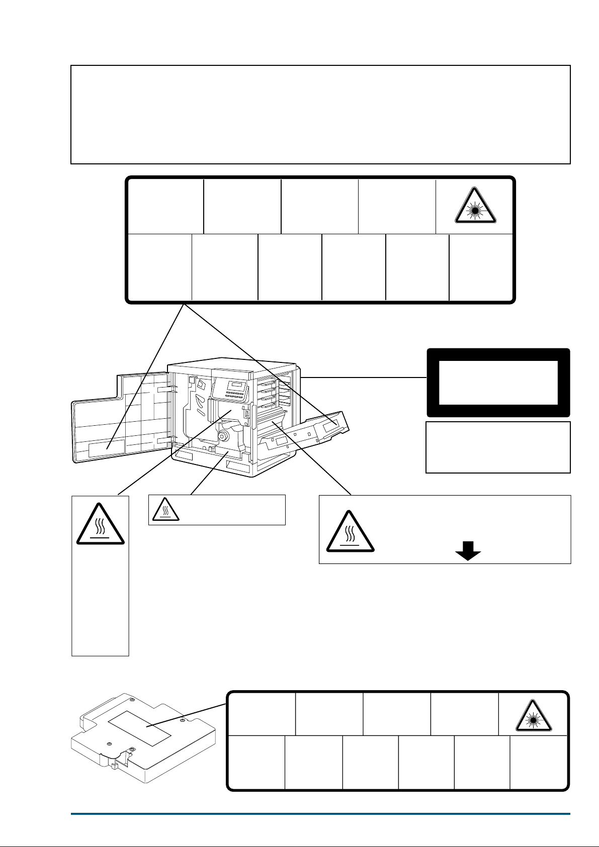
Laser diode properties
Laser output : 5 mW max
Wavelength : 780 nm
Emission duration : Continuous
Class 3B
ADVARSEL:
Usynlig laserstråling
når deksel åpnes og
sikkerhedslås brytes.
UNNGÅ
EKSPONERING
FOR STRÅLEN.
(220-240 VAC equipment)
CAUTION:
HOT SURFACE INSIDE
CAUTION:
HOT SURFACE
INSIDE
ATTENTION:
SURFACE
CHAUDE
CI-INTERIEUR
VORSICHT:
HEISSE FLÄCHE
INTERN
ATENCION:
SUPERFICIE
CALIENTE
EN EL INTERNO
Laser Scanning Unit (LSU)
CAUTION:HOT SURFACE BELOW
ATTENTION:SURFACE CHAUDE CI-DESSOUS
VORSICHT:HEIßE OBERFLÄCHE DARUNTER
ATENCION:SUPERFICIE CALIENTE ABAJO
i
Page 3

FS-5900C Service Manual
1. Introduction
1.1 Specifications ................................................................................................................. .................... 1
1.2 Options, Accessories and Supplies...................................................................................................... 5
1.3 Control Panel Overview ...................................................................................................................... 6
1.3.1 Message Display........................................................................................................................ 6
1.4 Rear Panel........................................................................................................................................... 8
1.4.1 Connectors................................................................................................................................. 8
1.4.2 Network card............................................................................................................................. 8
1.5 Parts Identification ............................................................................................................................. 9
1.5.1 Front side view.......................................................................................................................... 9
1.5.2 Rear side view ........................................................................................................................... 9
1.6 Component Layout...........................................................................................................................10
1.7 Electrical Components......................................................................................................................11
1.8 Switches/Sensors Identification ........................................................................................................12
2. Installation , Setup, an d Repa cking
2.1 Installation Requirements................................................................................................................. 13
2.1.1 Environment............................................................................................................................ 13
2.1.2 Minimum Space Requirements .............................................................................................. 13
2.2 Setup................................................................................................................................................14
2.2.1 Removing the Packing Material............................................................................................. 14
2.2.2 Installing the Optional Paper Feeder ....................................................................................14
2.2.3 Preparing the Imaging Unit ...................................................................................................14
2.2.4 Installing the Toner Developers............................................................................................. 15
2.2.5 Adding Paper or Transparencies............................................................................................ 16
2.3 Installing RAM SIMMs (Option) ........................................................................................................16
2.4 Replacing the Fuser Unit...................................................................................................................17
2.5 Replacing the Imaging Unit.............................................................................................................. 18
2.6 Repacking.........................................................................................................................................21
3. Mode Selection
3.1 Navigating through the Menus ........................................................................................................29
3.1.1 Display Information........................................................ ...... ....... ...... ....... ...... ....... ...... .. ..... .... 29
4. Mechanical Functions
4.1 Drive Mechanism/Image Process General Description....................................................................... 30
4.2 Print Process.....................................................................................................................................32
4.2.1 Discharging and Charging...................................................................................................... 32
4.2.2 Laser Exposure and Scanning................................................................................................32
4.2.3 Developing............................................................................................................................... 34
4.2.4 Toner Transfer to the Accumulator Belt ................................................................................ 35
4.2.5 Paper Pickup ...........................................................................................................................35
4.2.6 Toner Transfer to Paper..........................................................................................................36
4.2.7 Fusing and Exiting.................................................................................................................. 36
ii
Page 4

Table of Contents
5. Removal and Replacement Procedures
5.1 Upper Rear, Lower Rear and Top Covers............................................................................................38
5.2 Left Side Cover and Multi-purpose Tray ............................................................................................38
5.3 Operation Panel Cover and Printer LCD Board..................................................................................39
5.4 Safety Interlock Switches and Toner Empty Sensor Board (T)............................................................40
5.5 Front Cover and Bottom Front Cover................................................................................................4 1
5.6 Front Right Side, Rear Right Side and Lower Right Side Covers.........................................................42
5.7 Left Side Cover..................................................................................................................................43
5.7.1 Left Side Cover Removal .........................................................................................................43
5.7.2 Left Side Cover Sub Assembly................................................................................................43
5.8 Printer Main Control Board, HSYNC Board and Network Relay Board...............................................44
5.8.1 Printer Main Board Removal..................................................................................................44
5.8.2 Printer Main Control Board Disassembly, HSYNC Board and Network Relay Board........44
5.9 Paper Feed Unit ................................................................................................................................4 5
5.9.1 Paper Feed Unit Removal .......................................................................................................45
5.9.2 Paper Feed Unit Board and MP Tray Paper Out/Registration Sensor Board......................45
5.9.3 Transfer Roller Clutch, Transfer Roller Holder, Cleaning Roller Holder and
Registration Roller...................................................................................................................46
5.9.4 MP Tray Retard Pad................................................................................................................48
5.9.5 MP Tray Motor, MP Tray Pickup Roller and MP Tray Pickup Roller Shaft.........................49
5.9.6 Pickup Roller, Pickup Roller Shaft Assembly and Paper Empty Sensor Arm .....................51
5.9.7 Paper Feed Roller and Paper Feed Unit Frame.....................................................................52
5.10 Toner Developer Selector/Paper-eject Unit.........................................................................................53
5.10.1 Toner Developer Selector/Paper-eject Unit Removal.............................................................53
5.10.2 Covers, Sensor Boards (Paper Ejection, Paper Exit, Paper Tray Full) and
Paper Ejection Roller....... ...... ....... ...... ....... ...... ...... ....... .................................................... .. .... .54
5.10.3 Cam Motor Board, Toner Developer Movement Sensor Board and Toner Selector Cam....56
5.10.4 Joint Gear and Face Down Switch Back Solenoid.................................................................57
5.10.5 Switch Back Shaft, Switch Back Roller and Face Down Switch Gate..................................58
5.11 Engine Control Board Shield Cover...................................................................................................60
5.12 Laser Scanning Unit (LSU).................................................................................................................60
5.13 Power Supply Unit............................................................................................................................61
5.13.1 Power Supply Unit Removal ...................................................................................................61
5.13.2 Power Supply Unit Sub Assembly..........................................................................................61
5.14 Engine Control Board .......................................................................................................................6 2
5.15 Fuser/Toner Developer Fan Motor and Ozone Fan Motor ..................................................................62
5.16 Main Motor, Paper Feed Motor and Left Side Cover Switch..............................................................63
5.17 Transfer Roller Bias Terminal, FTR Bias Terminal, Home Sensor Board and Fuser Joint Connector ......63
5.18 IT Cleaning Solenoid Board and Toner Developer Drive Motor/Toner Developer Drive Unit ...............64
5.18.1 Removal (IT Cleaning Solenoid Board and Toner Developer Drive Motor/
Toner Developer Drive Unit)...................................................................................................64
5.18.2 Toner Developer Drive Unit Sub Assembly............................................................................65
5.19 Printer Main Control Board Holder, Printer Panel Relay Board and High Voltage Board ....................67
5.20 IT Belt Cleaning Drive Gears, Cleaning Clutch Shaft Assembly, Main Motor Bracket, Imaging Unit
Coupling Connector, Fuser Coupling Connector and Optional 2nd Feeder
Coupling Connector..........................................................................................................................68
iii
Page 5

FS-5900C Service Manual
5.21 Cassette Detection Sensor Board...................................................................................................... 69
5.22 Pre-Exposure Eraser and Pre-Transfer Boards.................................................................................... 69
5.23 Pre-Transfer Board Bracket and Toner Developer Guide Rails ............................................................70
5.23.1 Pre-transfer Board Bracket .................................................................................................... 70
5.23.2 Toner Developer Guide Rails.................................................................................................. 71
5.24 Cassette Guide, Fuser Guide Frame and Fuser/Paper Feed Unit Drive Gears...................................... 72
5.25 Fuser Unit Component (Heat Lamp, Thermal Fuse and Thermostat)................................................. 73
6. Electrical Circuit Description
6.1 Engine Block Diagram ......................................................................................................................75
6.2 Printer Main Control Board Block Diagram.......................................................................................76
6.3 Basic engine functions......................................................................................................................77
6.4 Engine controller system.................................................................................................................. 77
6.4.1 Configuration memory............................................................................................................ 77
6.4.2 High-voltage generator ................................ ...... ....... ...... ...... ....... ...... ....... ...... ....... ...... ....... .... 77
6.4.3 Laser scanner control.............................................................................................................. 77
6.4.4 Polygon motor control ............................................................................................................. 77
6.5 Safety interlock.................................................................................................................................77
6.5.1 The engine gate array............................................................................................................. 78
6.5.2 Power supply ............................ ....... ................................................... ....... .............................. 85
6.6 Logic controller system..................................................................................................................... 87
6.6.1 Printing data processing.........................................................................................................89
6.7 Main logic component .....................................................................................................................89
6.8 Print engine (video) interface ...........................................................................................................92
6.8.1 Physical Characteristics .........................................................................................................93
6.9 Interface Signals...............................................................................................................................94
6.9.1 Signal functions....................................................................................................................... 94
6.9.2 Serial control lines .................................................................................................................. 95
7. Setting the Colour Density
8. Preventative Maintenance
8.1 General................................................................................................................. .... ........................99
8.2 Recommended Tools.........................................................................................................................99
8.3 Recommended Cleaning...................................................................................................................99
8.4 Maintenance Tables........................................................................................................................100
8.4.1 User Maintenance.................................................................................................................100
8.4.2 Service Maintenance.......... ...... ....... ................................................... ....... ...... ...................... 10 1
9. Troubleshooti ng
9.1 Initial Troubleshooting Flowchart ................................................................................... ........... .....102
9.2 Error Messages............................................................................................................................... 103
9.2.1 Error Messages...................................................................................................................... 103
9.2.2 Call Service person Codes..................................................................................................... 105
iv
Page 6

Table of Contents
9.3 Jam.................................................................................................................................................108
9.3.1 Print Media Problem .............................................................................................................108
9.3.2 Print Media skews. ................................................................................................................108
9.3.3 Printer cannot distinguish between paper and transparency. ............................................108
9.3.4 Paper jams at the media cassette. ........................................................................................109
9.3.5 Paper jams midway in the paper feeder. ..............................................................................109
9.3.6 Paper jams at the second bias transfer roller.......................................................................110
9.3.7 Fuser Jams.............................................................................................................................110
9.3.8 Eject Jams..............................................................................................................................111
9.3.9 Multi-purpose Tray Jams......................................................................................................111
9.4 Print Quality....................................................................................................................................112
9.4.1 Blank Print.............................................................................................................................112
9.4.2 All-black Print........................................................................................................................112
9.4.3 Missing Primary Colour ........................................................................................................113
9.4.4 Light Print..............................................................................................................................113
9.4.5 Repeated spots or lines on print in-line with each other.....................................................114
9.4.6 Dark Vertical Line in Print ...................................................................................................114
9.4.7 White horizontal line or band in all the colours of a print ..................................................115
9.4.8 Mis-transfer, missing portions of toner.................................................................................115
9.4.9 Dirty Background ..................................................................................................................115
9.4.10 Partial Black Dots..................................................................................................................115
9.4.11 Dark Irregular Streaks in All Colours...................................... ...... ....... ...... ....... ...... ....... .....116
9.4.12 Ghosting .................................................................................................................................116
9.4.13 Unfused or Partially Fused Printing....................................................................................116
9.4.14 Image is skewed on the paper. ..............................................................................................116
9.4.15 Stains on Back of Print..........................................................................................................117
9.4.16 No Printing on Edge of Print.................................................................................................117
9.4.17 Image is not centered on the print when it should be. ........................................................117
9.5 Printer Error (Call Service person) ...................................................................................................118
9.5.1 BB/B8/B9/BA..........................................................................................................................118
9.5.2 A6............................................................................................................................................119
9.5.3 E2/E3......................................................................................................................................119
9.5.4 A5............................................................................................................................................120
9.5.5 AC...........................................................................................................................................122
9.5.6 AD...........................................................................................................................................124
9.5.7 AE...........................................................................................................................................125
9.5.8 AF ...........................................................................................................................................126
9.5.9 B7............................................................................................................................................127
9.5.10 A2............................................................................................................................................128
9.5.11 E4............................................................................................................................................130
9.5.12 A7............................................................................................................................................130
9.5.13 A8............................................................................................................................................131
9.5.14 AA ...........................................................................................................................................132
9.5.15 AB ...........................................................................................................................................133
9.5.16 E1............................................................................................................................................134
9.5.17 A9............................................................................................................................................135
9.5.18 E6............................................................................................................................................135
9.5.19 BC ...........................................................................................................................................135
9.5.20 BD...........................................................................................................................................136
9.5.21 E0............................................................................................................................................136
9.5.22 BE ...........................................................................................................................................137
v
Page 7

FS-5900C Service Manual
9.5.23 BF...........................................................................................................................................137
9.5.24 Call Service person F0 .......................................................................................................... 137
9.5.25 Memory Overflow............................ ...... ....... ...... ....... ...... ...... ................................................ 138
9.5.26 Call Service person F2 .......................................................................................................... 138
9.5.27 Call Service person F3 .......................................................................................................... 139
9.6 No Message Section.......................................................................................................................140
vi
Page 8

1. Introduction
1.1 Specifications
CPU PowerPC 603e (100 MHz)
Printing Method Semiconductor Laser
1. Introduction
Printer
Host I/F Standard : Bidirectional Parallel, Serial (8-pin DIN)
Print Speed The speeds listed in the following table represent the time the printer pro-
Resolution 600 × 600 dpi
Paper Output Up to 500 sheets [75 g/m
Option: Network inte rface card
duces multiple prints on various media and resolution (Continuous
throughput rate).
Continuous Print Speeds (ppm)
Simplex
600 × 600 dpi
Plain Paper colour: 4
Legal colour: 2
Labels, Coated, Card Stock, 2nd Side colour: 2
Transparency colour: 2
1200 × 1200 dpi
Plain Paper colour: 2
Legal colour: 1
Labels, Coated, Card Stock, 2nd Side colour: 2
Duplex
600 × 600 dpi
Plain Paper colour: 2
Legal colour: 1
1200 × 1200 dpi
Plain Paper colour: 1
Legal colour: 0.5
1200 × 1200 dpi (additional RAM required)
2
(20 lbs.)]
mono: 16
mono: 8
mono: 8
mono: 8
mono: 8
mono: 4
mono: 8
mono: 4
mono: 2
mono: 2
mono: 1
RAM Standard 48 MB (expandable to a maximum of 112 MB with optional
Operating Environment Temperature: 10 to 32.5 °C (50 to 90.5 °F)
Storage Environment Temperature: 0 to 40 °C (32 to 104 °F)
Best Print Quality Temperature: 16 °C to 27 °C (59 °F to 77 °F)
Operating Altitude 0 to 2,500 m (8,000 ft.)
Storage Altitude 0 to 4,000 m (13,125 ft.)
Warm Up Time Less than 330 seconds (at 22 °C, 50 %RH)
Dimensions of Standard
Unit (without Paper Feeder)
SIMMs)
Humidity: 15 to 80 % RH
Humidity: 10 to 80 % RH
Humidity: 36 to 63 % RH
Height: 462 mm (18.2")
Depth: 493 mm (19.4")
Width: 510 mm (20.1") [784 mm (30.9") with the output tray]
1
Page 9

FS-5900C Service Manual
Printer
Mass (Weight) of standard
unit with all consumables
(without optional Paper Feeder)
51 Kg (112 lbs.)
Voltage 120 VAC ±10 %
Frequency 60 Hz
Power Consumption 920 W Max.
210 W (standby)
Less than 45 W (Energy Star mode), meeting the Energy Star power conser-
vation requirements
Noise Level 53 dB(A) [Printing mode]
47 dB(A) [Standby mode]
Density Control Variable (through the operator panel [MODE key])
Fusing System Heat and Pressure Rollers
Photoreceptor Organic Photoconductor (OPC) Belt
Development Process One component non magnetic development
Toner Yielding
(5% image area)
12,000 pages average (Black toner developer),
10,000 pages average (C.M.Y toner developers)
Safety and EMC Standard For the 120 VAC version: UL 1950 listed
FCC Part 15, Subpart B Class B, certified
Paper Weight Media cassette*
Simplex
mono: 60 to 105 g/m
colour:75 to 105 g/m
2
(16 to 28 lbs.)
2
(20 to 28 lbs.)
Paper
Duplex
mono: 75 to 90 g/m
colour:75 to 90 g/m
2
(20 to 24 lbs.)
2
(20 to 24 lbs.)
Multi-purpose tray
Simplex only
mono: 75 to 165 g/m
colour:75 to 165 g/m
2
(20 to 44 lbs.)
2
(20 to 44 lbs.)
Thickness 3.7 to 7.5 mils (1 mil=1/1000")
Moisture Content 4% to 6%
Smoothness 100 to 300 Sheffield
Acid Content 5.5 PH minimum
Fusing Compatibility Must not scorch, melt, offset material or release hazard ous emissions when
heated to 200 °C (392 °F) for 0.1 second
Cutting Dimensions ±0.0313 inch of normal, corners 90° ±4°
Grain Long grain
Cut Edge Conditions Cut with sharp blades, no paper dust
Ash Content Not to exceed 10 %
Curl No allowable curl toward the side to be printed
Packing Polylaminated moisture proof ream wrap
Paper Size A4 8.3" × 11.7" (210 × 297 mm)
Legal 8.5" × 14" (216 × 356 mm)
Letter 8.5" × 11" (216 × 279 mm)
Transparency Size A4 8.3" × 11.7" (210 × 297 mm)
Letter 8.5" × 11" (216 × 279 mm)
2
Page 10

1. Introduction
Types of paper to avoid
1. Extremely smooth or shiny paper or paper that is highly textured
2. Letterhead imprinted with low temp erature or thermography. These materials may transfer onto the fusing roller
and cause damage. Any pre-printed paper should use inks compatible with 200 °C (392 °F) for 0.1 second.
3. Damaged or wrinkled paper, or paper with irregularities such as tabs, staples, etc.
4. Multipart forms or carbonless paper
5. Paper with a 25% or more cotton and/or fiber content
6. Ink jet paper (It may transfer onto the fuser roller and cause damage.)
* We do not recommend the use of 1 05 g/m
paper feed problems may be experienced.
2
(28 lbs.) paper in areas of high or low humidity and temperature since
Device Cables (Not included with the Printer)
Cables Description
Parallel/Centronics
Serial Requires a Kyocera cable adaptor SA-80 which converts 8-pin DIN to 25-pin DSUB config-
36-pin high-density plug to 25-pin DSUB plug; less than 2.0 m (6.56 ft.)
Connects the printer to a PC parallel port
uration.
Specifications are subject to change without notice.
Trademark Acknowledgements
Windows is a registered trademark of Microsoft Corporation in the United States and/or other countrie s.
Pentium is a registered trademark of Intel Corporation.
Corel is a trademark of Corel Corporation.
Adaptec is a registered trademark of Adaptec, Inc.
Centronics is a trademark of Centronics Data Computer Corporation.
TextBridge is a registered trademark of Xerox Corporation.
Adobe and Acrobat are trademarks of Adobe Systems Incorporated.
All other acknowledgments are trademarks or registered trademarks of their respective holders.
Acrobat Reader copyright 1987-1999 Adobe Systems Incorporated. All rights reserved.
As an Energy Star Partner, Kyocera Corporation has determined that this product meets
the Energy Star g uidel ines fo r e nergy ef fici ency. The international Energy StarSM Lo go i s
valid in U.S.A., Europe and Japan only.
All about media
• The recommended media is as follows:
Letter/Legal: Hammermill LASERPRINT 90 g/m
A4: NEUSIEDLER COLOR COPY 90 g/m
For the finest resolution and the brightest, most consistent colours, use a high grade laser paper. The
weight of the paper should be 60-105 g/m
2
(16-28 lbs.) paper in the media cas settes; and 75-120 g/m2 (20-
32 lbs.) in multi-purpose tray.
Transparency: 3M CG3700 and 3M CG3710
2
(24 lbs.)
2
(24 lbs.)
3
Page 11
FS-5900C Service Manual
• Labels
Use only full 8.5" × 11" or A4 label sheets rath er tha n die-cut l abel sheets t hrough t he mult i-purp ose tray.
Die-cut labels may peel off from their backing and stick inside the imaging unit or fuser.
• Envelopes
This printer prints black text only using the following high quality #10 laser envelopes with diagonal
steams. Do not insert more than one envelope at a time.
• A thin, sharply creased leading edge.
2
• Paper weight of 90 g /m
(24 lbs.)
• Flat and free of curls, wrinkles, nicks, etc.
• Make sure that the media cassettes are free of dust. Du st and dirt in a media cassette can be transferred
to the paper or transparency, resulting in poor print quality.
• Handle paper and transparencies with both hands at the edges to avoid creases and fin gerprints, which
can result in poor print quality.
• Store paper and transparencies in the original dust-free package.
• To prevent transparencies or paper from sticking together, fan them before loading into the appropriate
media cassette.
• If the optional paper feeder is used: A media cassette can be installed in any of the three tray slots; however, the transparency tray should only be inserted in the upper and middle tray slots.
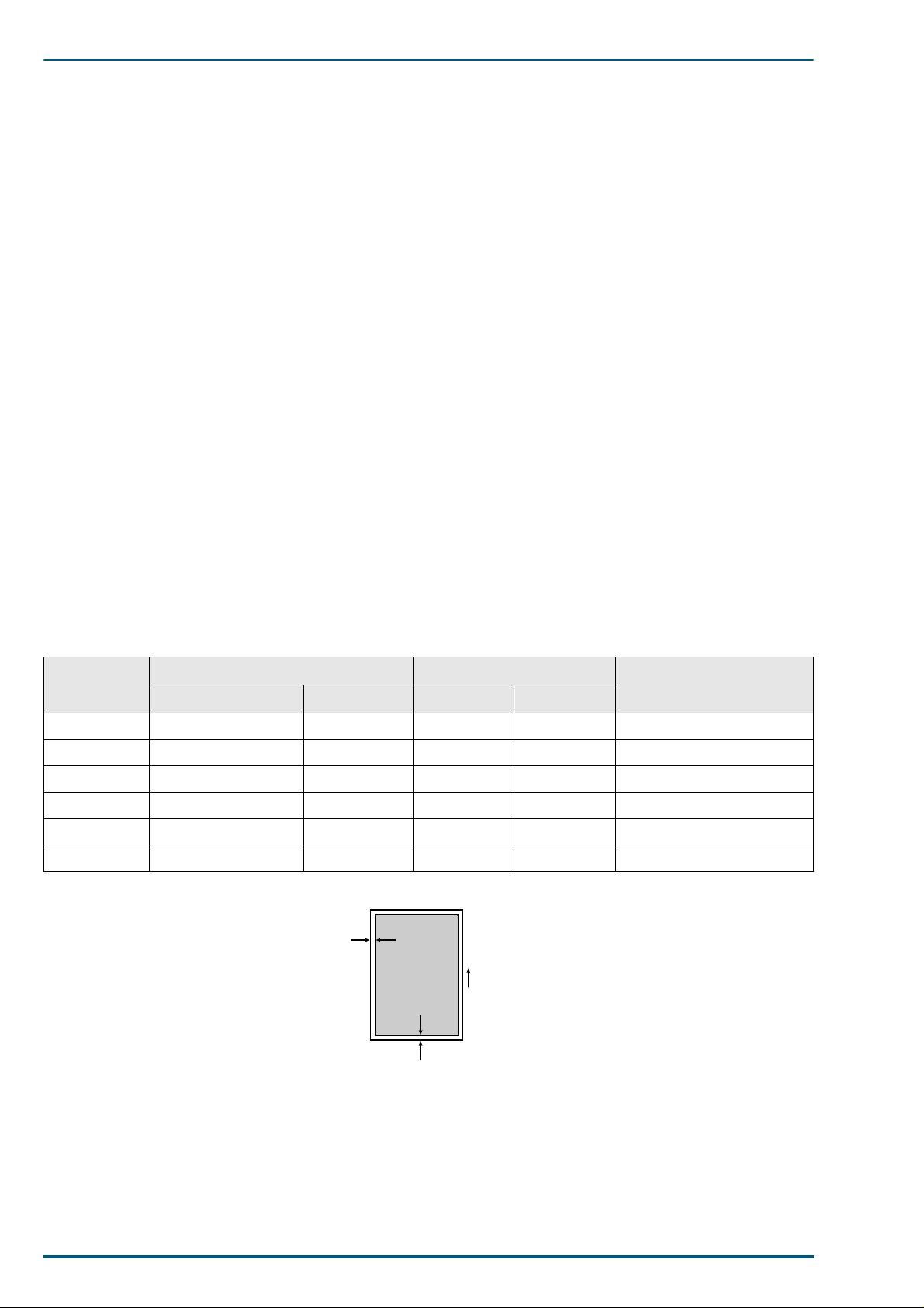
Margins and Print Area
When the printer places an image on media, the image (print area) is a bit smaller than the media size.
Page margins adjustment may be needed in an application software to match the pr int area.
The following table lists the page sizes, the maximum print areas, and the margins for the media sizes supported in KPDL emulation, 600dpi.
Media
cm/inch Points Horizontal Vertical
A4 21.0 × 29.7 595 × 842 112 120 4736 × 6784
B5 18.2 × 25.7 516 × 729 174 97 3950 × 5875
ISO B5 17.6 × 25.0 499 × 708 99 102 3958 × 5700
Legal 8.5 × 14 inches 612 × 1008 86 136 4928 × 8128
Letter 8.5 × 11 inches 612 × 792 86 132 4928 × 6336
Executive 7.25 × 10.5 inches 522 × 756 100 100 4150 × 6100
Page Size Edge limitis (A) (dot)
B
Horizontal
edge limit
Printable area
Direction of paper
feeding
Printable area (B) (dot)
A
Vertical edge limit
RAM and printer capabilities
The printer features 16 Mbytes of base RAM and a 32-Mbyte SIMM fit in the one of the three connectors
that accept 4, 8, 16 and 32-Mbyte RAM SIMMs. With additional RAM memory the printer’s capabilities
increase as follows:
4
Page 12

1. Introduction
When using the Printer Driver and Utilities
Total Memory Selectable Print Quality Mode Printable without Memory Overflow
48 MB (Stan dard)
56 MB (8MB added)
72 MB (24MB added) Letter, A4, Legal
* Documents can be printed on Legal size paper when the print style is set to Color Graphics provided the data size of
the documents is small.
Fast (300 dpi) Letter, A4, Legal
Standard (600 dpi) Letter, A4*
Letter, A4*
High Quality (1200 dpi)
1.2 Options, Accesso r ies and Supplies
Item Description
PF-81
PF-81D
HB-7SNMP
EcoLAN 2000E
TD-81K
TD-81C
TD-81M
TD-81Y
Paper Feeder
Paper Feeder/Duplex Unit
Network Card for Ethernet
Toner developer: Black
Toner developer: Cyan
Toner developer: Magenta
Toner developer: Yellow
FK-81
IU-81
TR-81
OS-81
SA-80
HD-2C
CP-81
MC-81
Fuser
Imaging unit
Transfer unit
Oil Supply Roll
Serial Adapter
HDD unit (2GB)
Cleaning pad for the fuser
Main charger
5
Page 13

FS-5900C Service Manual
1.3 Control Panel Overview
The printer has the following displays and keys. Simple explanation the displays follows. For a full information on using them, refer to the printer’s User’s Manual (also on the CD-ROM).
1.3.1 Message Display
The message display displays the printer’s operati onal mode. Messages which are displayed and their
meanings are as follows:
Message Meaning
Self test
Please wait
Ready
Processing
Waiting
FormFeed TimeOut
Interface Indicator
The interface indicator indicates the interface over which data is currently being received or was last
received. The current interface is indicated by one of the following messages:
The printer is self-testing after power-up and is not ready to print. This message appears only
at power-up.
The printer is warming up and is not ready to print.
The printer is ready to print.
The printer is processing print data or in the middle of printing.
The last page remains unprinted. The printer waits awhile and eventually generates a form
feed allowing the last page to be printed. (The length of time depends on the form feed timeout
setting.) The printing will begin immediately when the
card is being used this can indicate the printer is waiting for data to be written.
An automatic form feed has been generated.
Form Feed
key is pressed. If a memory
Display Description
PAR
SER
OPT
Note:
The display will blink while the printer is receiving data and continue blinking until the interface is
Parallel interface
Serial interface
Optional interface (if a network interface card is installed)
released, even after data transmission is finished.
6
Page 14

1. Introduction
Resolution Indicator
This shows the current printing resolution in either 1200 or 600 dpi (dot-per-inch).
Paper Size Indicator
This indicator indicates the paper size of the cassette currently selected. The following abbreviations are
used to indicate the paper sizes:
Indicator Paper Size
A4
EX
B5
LT
LG
b5
* These paper sizes can only be fed from the MP tray.
ISO A4 (21 × 29.7 cm)
Executive (7-¼ × 10-½ inches)*
JIS B5 (18.2 × 25.7 cm)*
Letter (8-½ × 11 inches)
Legal (8-½ × 14 inches)
ISO B5 (17.6 × 25.0 cm)*
Copy Indicator
This indicator indicates the number of copies to print from 001 to 999. This number is reduced as printing
proceeds.
7
Page 15
FS-5900C Service Manual
1.4 Rear Panel
1.4.1 Connectors
The rear panel is equipped with the following interface connectors:
• Parallel (high densit y conne cto r)
• Serial (8-pin mini DIN-type connector)
A converter cable that allows the serial connector to a DSub connector is opt ionally available by the model
number SA-80.
1.4.2 Network card
The network interface card is available in either Ethernet or TokenRing protocol as follows.
See your nearest dealer of the manufacturer for availability.
Manufacturer Model Applicable country
HBM HB-7SNMP Available in UK and France
Ethernet
Token Ring SEH IC69-Token-KYO2 All countries
Two LEDs on the face of the optional network card verify LAN connection and network activity.
DPI EcoLAN 2000E Available in USA and Japan
SEH IC59-ETHER-KYO2 Other countries
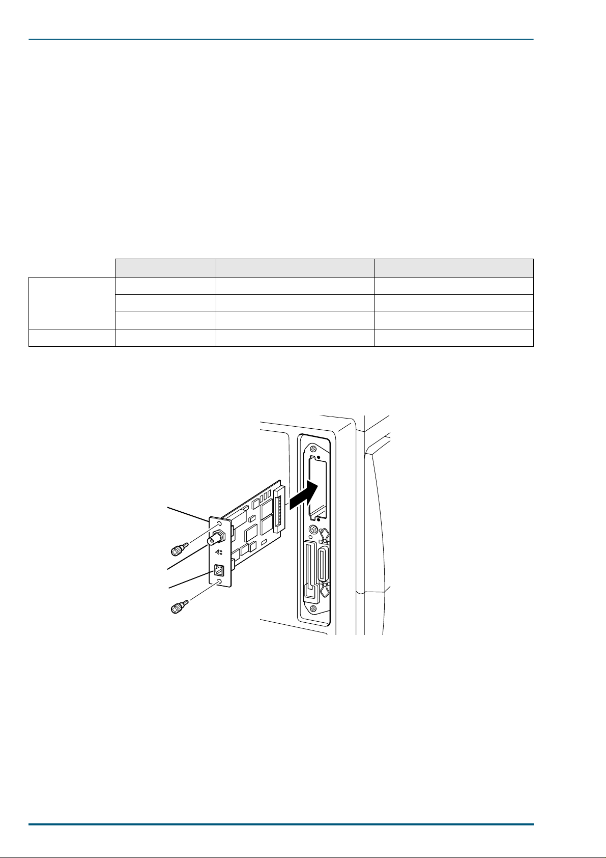
Installing the Network Card
Example:
HB-7SNMP EcoLAN 2000E
10BASE2
10BASE-T
8
Page 16
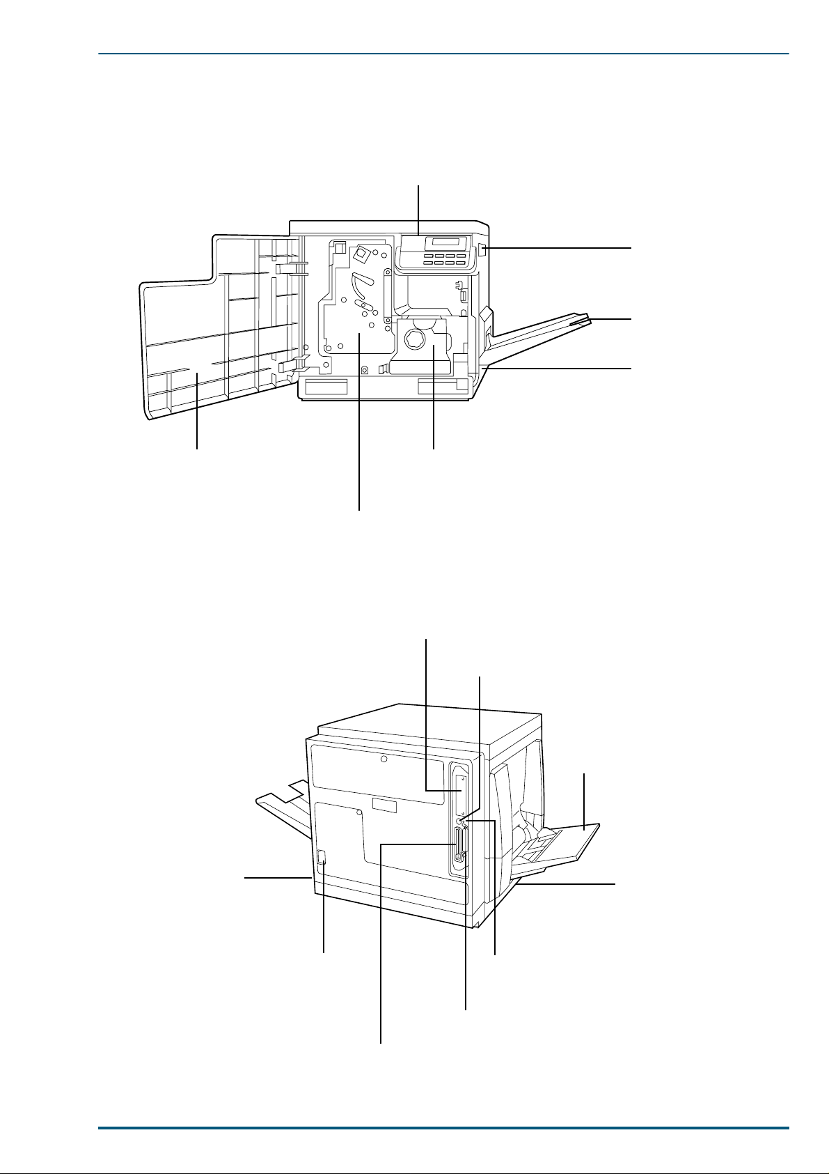
1.5 Parts Identification
1.5.1 Front side view
1. Introduction
Control panel
Right side cover
Output tray
Media cassette
Front cover
1.5.2 Rear side view
Fuser
Imaging unit
Network interface card slot
Serial interface connector
Multi-purpose (MP) tray
Power switch
AC inlet
Left side cover
[Media thickness switch*]
* Accessible by opening the
left side cover
Harddisk access
indicator
Parallel interface co nnect or
Memory card connector
9
Page 17
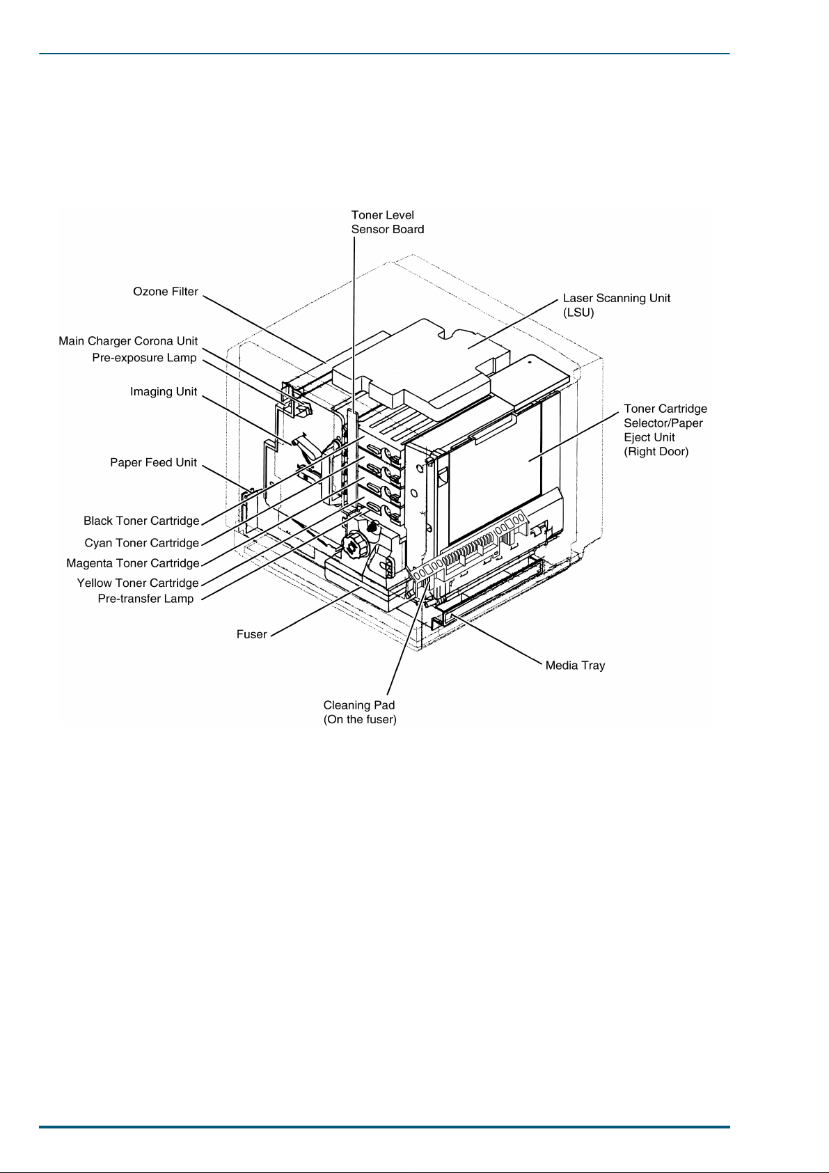
FS-5900C Service Manual
1.6 Component Layout
10
Page 18
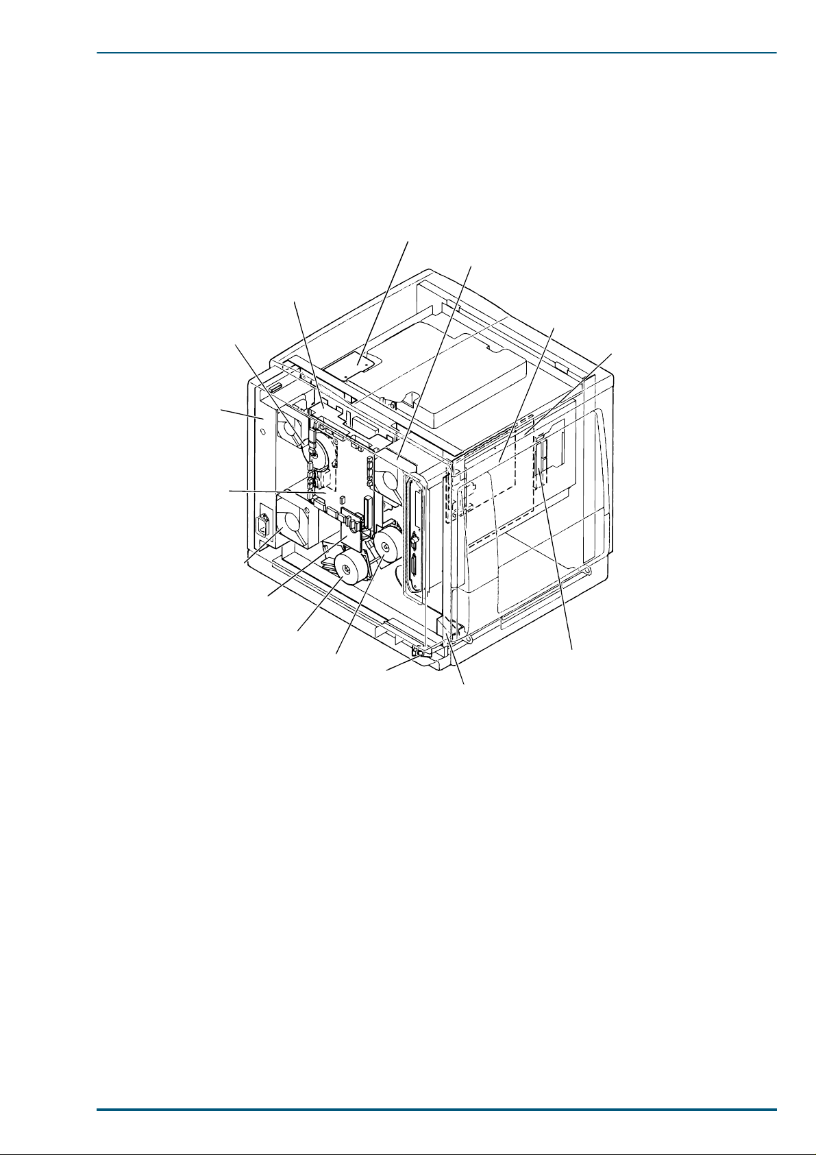
1.7 Electrical Components
Toner Cartridge
Drive Unit
Toner
Cartridge
Motor
Power
Supply
Unit
1. Introduction
Polygon Motor
Driver Board
Ozone Fan
High Voltage
Board
Main Control Board
Engine
Control
Board
Fuser/Toner
Cartridge Fan
Cleaning Board
Paper Feed Motor
Main Motor
Temperature/
Humidity
Sensor Board
Interconnect
Board
Lower Door Open
Sensor
11
Page 19
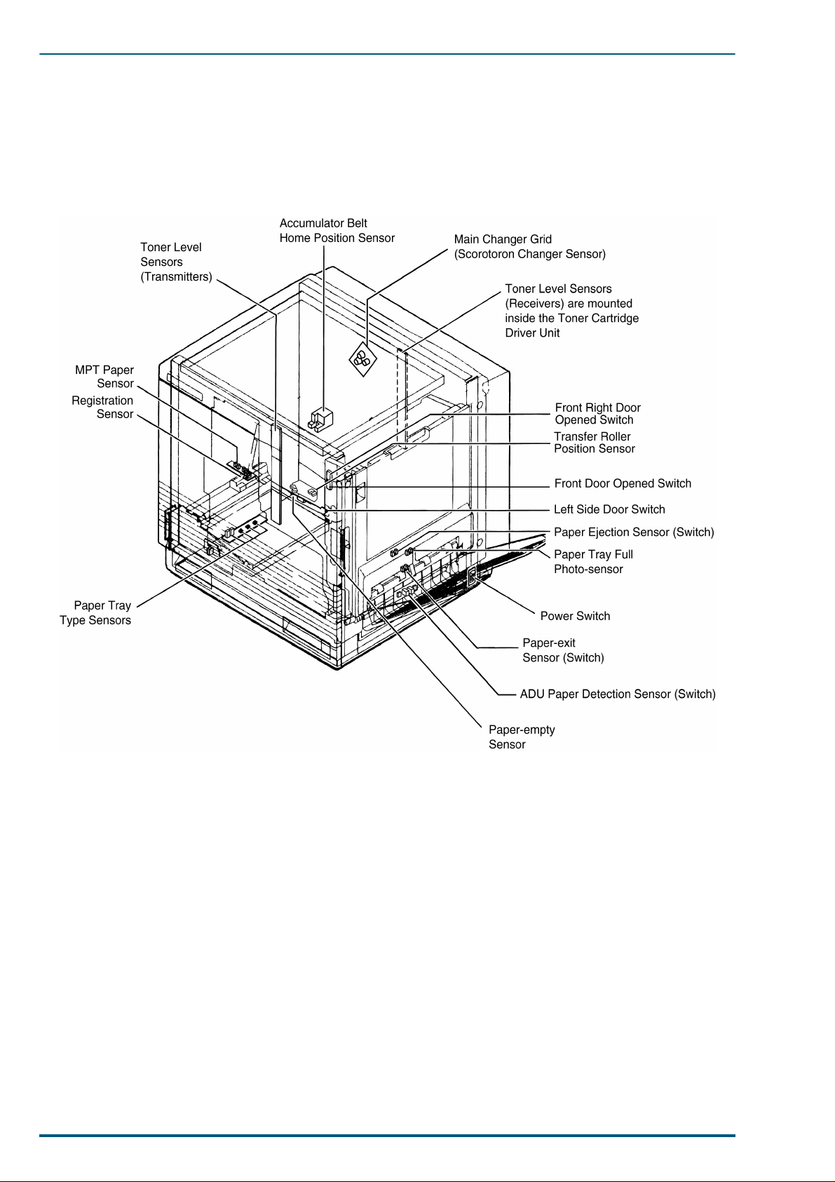
FS-5900C Service Manual
1.8 Switche s/Sensors Identification
12
Page 20
2. Installation, Setup, and Repacking
2. Installation, Setup, and Repacking
2.1 Installation Requirements
2.1.1 Environment
Temperature Range: 10°C to 32.5°C [50°F to 90.5°F] (Temperature fluctuation: ±10°C per hour or less)
Humidity Range: 15% RH to 80% RH (Humidity fluctuation: ±20 °C per hour or less)
Weight: 51 kg (112 lbs.)
Precautions for installation
Place the unit on a stable, level surface.
Do not install the unit under the following conditions:
• Extremely high or low temperature
• Extremely high or low humidity
• Direct exposure to sunlight
• Areas of high dust concentration
• Areas of poor ventilation
• Areas exposed to chemical fumes
• Areas with extreme vibration
• Directly in air conditioning flow
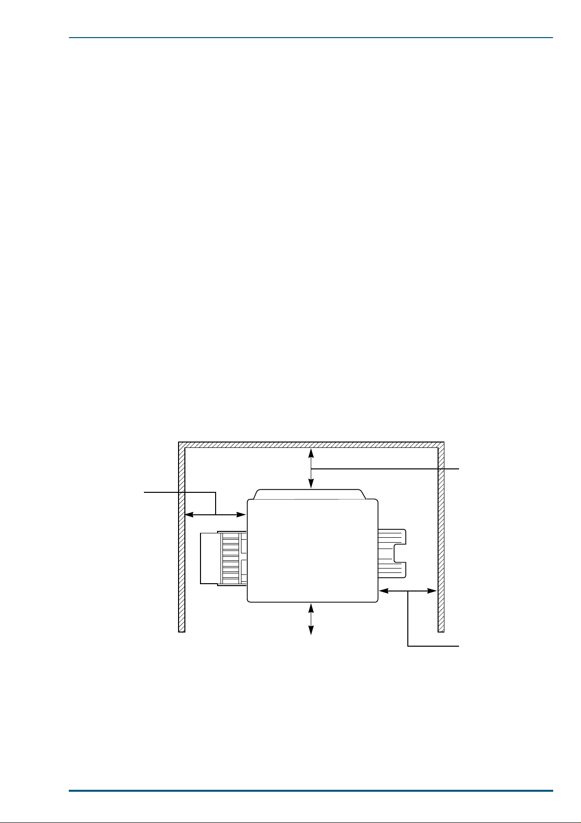
2.1.2 Minimum Space Requirements
Allow air flow around the printer to prevent overheating. The following minimum spaces are required:
Rear
35 cm (13.8")
Controller Board
45 cm (17.7")
Output
tray
Left Right
Multi-purpose Tray
Front cover
50 cm (19.7")60 cm (23.6")
13
Page 21
FS-5900C Service Manual
2.2 Setup
2.2.1 Removing the Packing Material
1. Remove the plastic bag from the printer.
2. Remove any adhesive tape that holds the output tray against the printer.
Note:
Do not throw away the packing materials. They may be required to ship or transport the printer in
the future. To provide optimum print quality , the unit must be kept upright and level during unpacking.
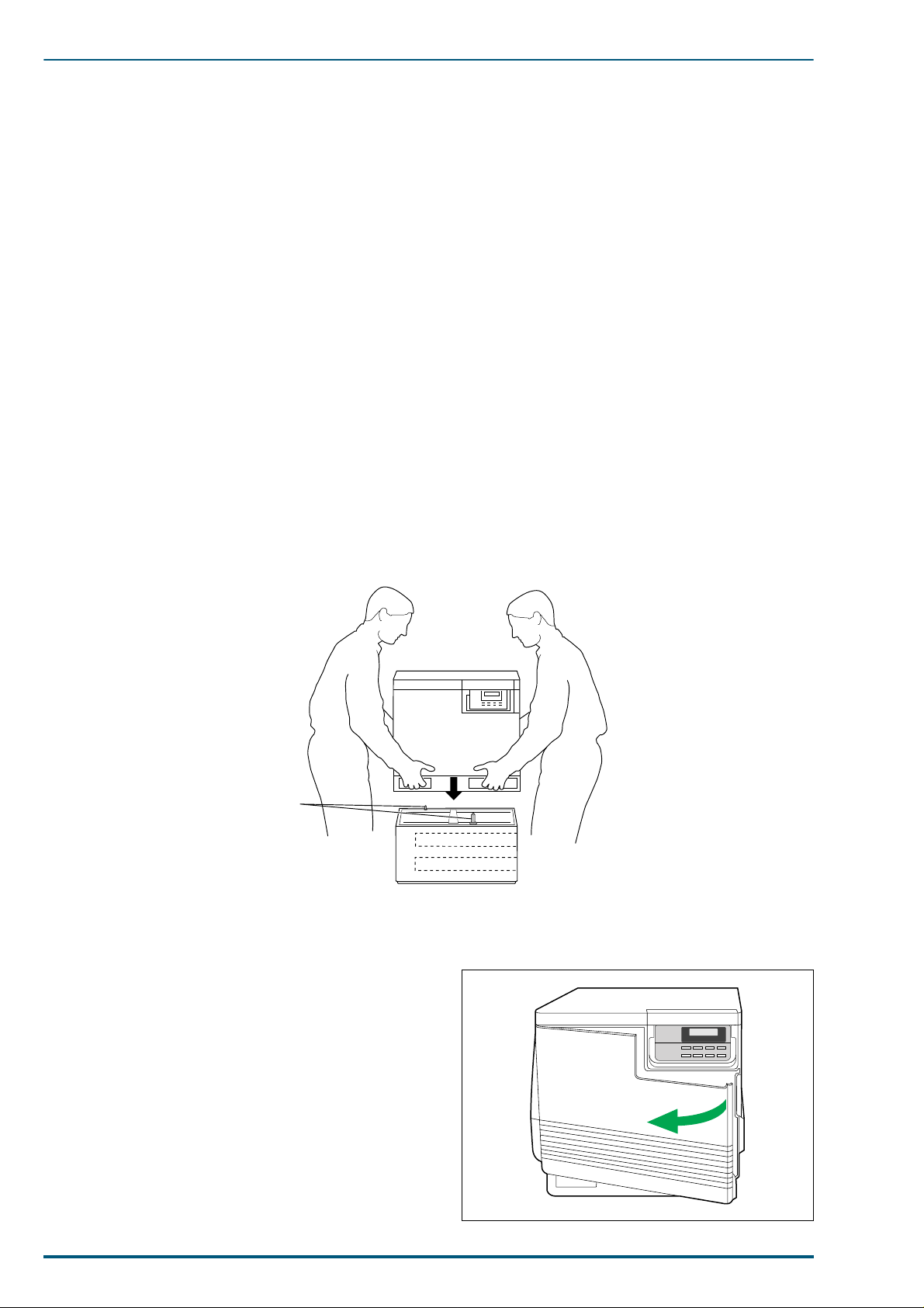
2.2.2 Installing the Optional Paper Feeder
Warning:
Warning:
1. Place the paper feeder on a solid table or cart selected for the printer.
2. Place the printer on top of the paper feeder. Always keep the printer upright.
3. Make sure that the left and right alignment pins fit in the holes in the base of the printer.
The printer weighs about 51 kg (112 lbs.) and the paper feeder weighs about 14.4 kg (36.3 lbs.).
Observe standard precautions for lifting heavy objects.
The printer is not permanently attached to the paper feeder. When moving the printer, turn
the power off and remove the power cord, then move the pieces separately; moving the printer
incorrectly may damage it and may cause personal injury.
Alignment pins
(Left door side) (Cassette slots side)
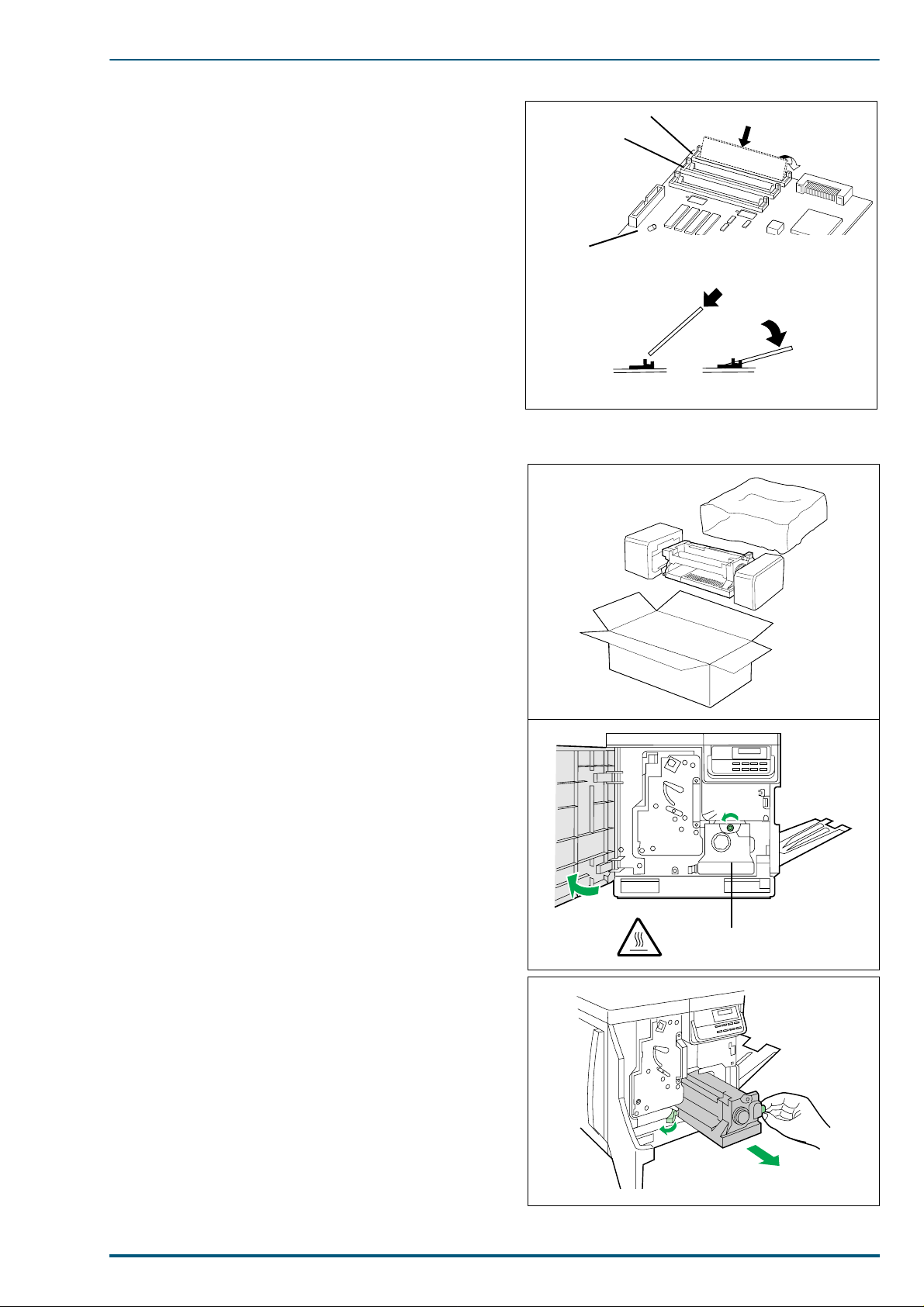
2.2.3 Preparing the Imaging Unit
1. Open the front door.
Paper Feeder
14
Page 22
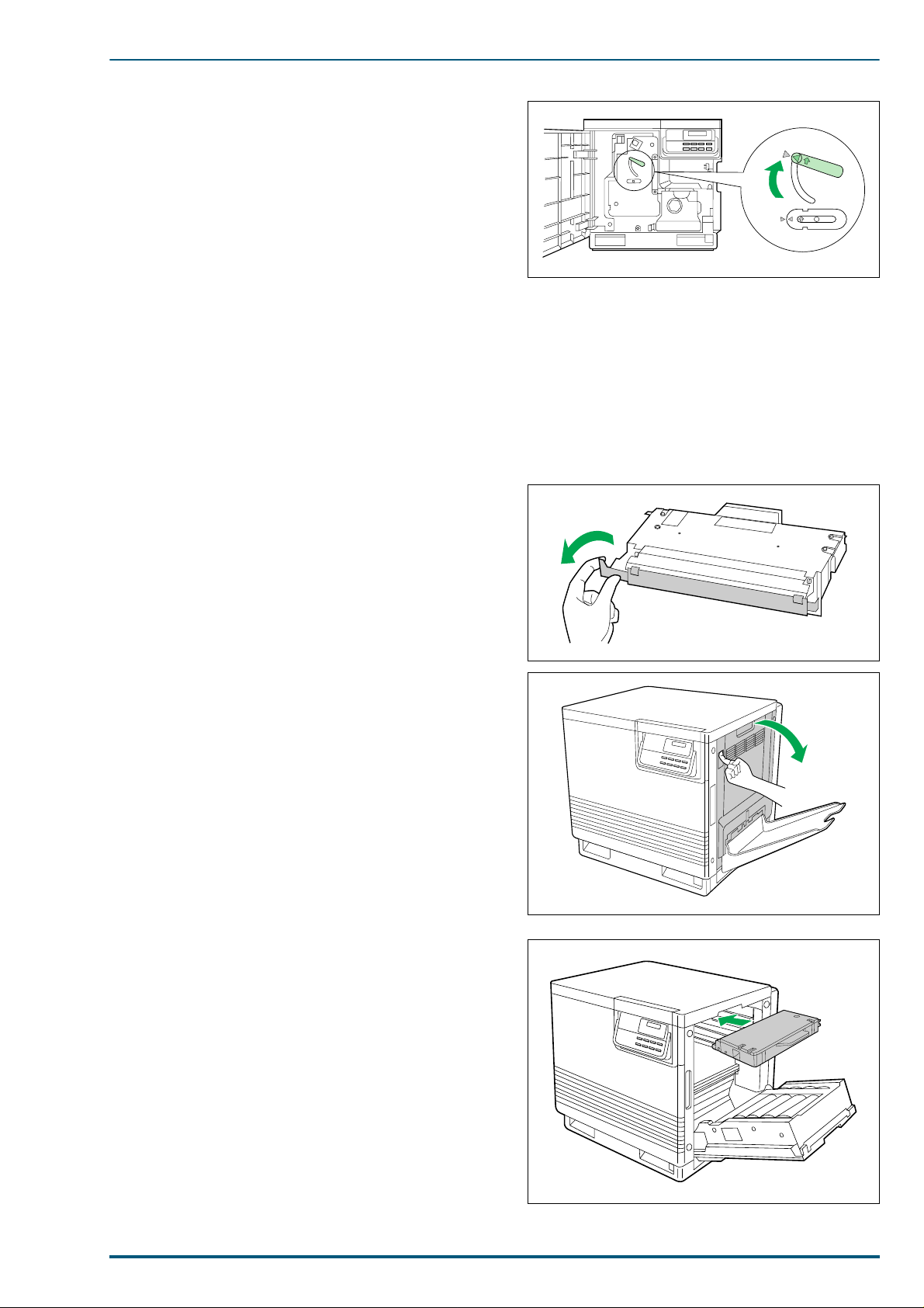
2. Turn the upper green lever clockwise until it stops
and the arrows are aligned. (This applies tension to
the internal belts).
3. Close the front cover.
2.2.4 Installi ng the Toner Developers
2. Installation, Setup, and Repacking
Note:
The toner developers shipped with the printer are starter developers. They are installed in exactly
the same manner as t h e standard developers; the only difference is that the starter developers have
less toner. (Page life expectancy is 5,000 pages for all toner developers except black which has a life
expectancy of 6,000 pages.)
1. Remove the packaging from the toner developer.
2. Remove the shipp ing cover from the developer.
Caution:
Do not tilt the developer to avoid possible
toner spillage.
3. Open the printer’s right side door.
Caution:
Do not leave the right side door open for a
long time; the imaging unit inside is exposed
to light and will be damaged.
4. Insert the toner developer in the appropriately
labeled slot. From top to bottom, the developer order
is BLACK, CYAN, MAGENTA, and YELLOW.
15
Page 23
FS-5900C Service Manual
5. Repeat steps 1, 2 and 4 for each toner developer.
6. When all the toner developers have been installed,
close the right side door.
Note: Save all packing material for shipping purposes.
2.2.5 Adding Paper or Transparencies
The printer is shipped with one media cassette of either Letter or A4 paper size. The printer can also use
five different cassettes as follows:
Tray Size
A4 Paper 210 × 297 mm (8.27" × 11.7")
A4 Transparency 210 × 297 mm (8.27" × 11.7")
Letter Paper 8.5" 11" (216 × 279 mm)
Letter Transparency 8.5" × 11" (216 × 279 mm)
Legal paper 8.5" × 14" (216 × 356 mm)
Notes:• Make sure that correct media is loaded. Each cassette is designed and labeled for only paper or
transparency. If the wrong media type is loaded in a tray, an error message will be displayed
when printing is attempted.
• If the paper feeder is installed and the automatic tray switching feature (for example, for a large
print job) is used, make sure that all trays in the printer at any one time are the same media type
and size.
• To optimize the printer’s performance, always use clean, unused media.
• Be careful not to leave fingerprints on the media, which can result in a smudged print.
• Reusing media that has been fed through the printer (for example, after jams or if the media is
ejected without being printed) can reduce the life of the consumables and paper path components.
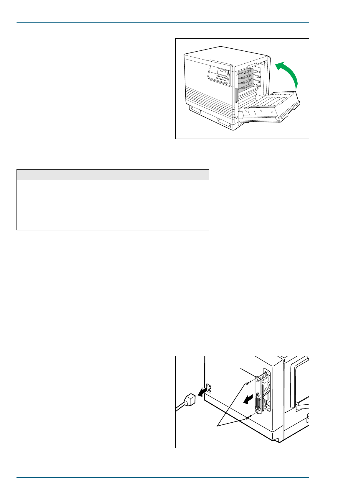
2.3 Installing RAM SIMMs (Option)
1. Turn off the printer. Do not unplug the printer; this preserves a ground path to dissipate static charges.
2. Remove the two screws from the controller board.
3. Pull out the controller board.
Controller Board
4. When installing a single RAM SIMM:
Insert a memory module in connector YS3 or YS4 and
tilt the module down until it locks in place. When the
SIMM is properly inserted, a tab on each end of the
connector slips into a hole on each end of the RAM
SIMM. Also, a pawl on each end of the connector
latches around each end of the RAM SIMM to lock it
in place. Go to step 6.
16
~AC IN
Screws
Page 24
5. When installing two RAM SIMMs:
YS4
YS3
Controller Board
a b
HOT SURFACE INSIDE
Insert the appropriate memory module in connector
YS3 and YS4 and tilt the module down until it locks
in place. When the SIMM is properly inserted, a tab
on each end of the connector slips into a hole on each
end of the RAM SIMM. Also, a pawl on each end of
the connector latches around each end of the RAM
SIMM to lock it in place.
6. Reinstall the controller board.
7. Reinstall the two screws.
2.4 Replacing the Fuser Unit
1. Remove the new fuser from its packaging; keep the
fuser upright.
2. Installation, Setup, and Repacking
2. Open the front doo r. Turn the small green thumb-
screw counterclockwise to unlock the fuser.
Caution:
The fuser is hot; to avoid personal injury,
wait approximately 10 minutes for the fuser
to cool before touching it.
3. Grasping the green tab on the right, slide the fuser
out until the safety catch stops it. Press the green
lever on the left to release the safety catch.
17
Page 25

FS-5900C Service Manual
4. Hold the fuser as shown and slide it out of the
printer. Dispose of the fuser as normal office waste.
Caution: The fuser weighs approximately 3.2 kg (7.11
lbs.). Take care when handling it.
5. Insert the new fuser into the printer.
6. Turn the small green thumbscrew clockwise to lock
the fuser. Close the front door.
2.5 Replacing the Imaging Unit
1. Open the front door. Loosen the two thumbscrews by
turning them counterclockwise. Turn the lower green
lever 180° counterclockwise.
18
Page 26
2. Grasping the front gree n handle, slide the unit out
until it catches. Lift up the green handle on the left.
Pull the imaging unit out of the printer.
Caution: The imaging unit weighs approximately 6.5
kg (14.3 lbs.). Always use the handles when
lifting it.
3. If the imaging unit is to be reinstalled, cover it with
an empty box or place it in a dark cabinet to protect it
from light exposure. If the unit is to be discarded,
dispose of it as normal office waste.
Important:
Do not expose the imaging unit to light for more than
approximately 45 seconds, or irreversible damage may
result.
2. Installation, Setup, and Repacking
4. Remove the new imaging unit from the packaging.
The imaging unit is extremely light-sensitive. Leave
the protective plastic sheet on the imaging unit
immediately before installin g it.
Note:
Save all packing material for future shipping purpose.
19
Page 27
FS-5900C Service Manual
5. Remove the used filter by pulling it forward. Dispose
of the filter as normal office waste. Insert the new
filter.
6. Turn the upper green lever clockwise until it stops.
Ozone Filter
7. Remove the protective plastic sheet.
Important:
• Do not touch the green surface. Fingerprints may a ffect
the print quality.
• Do not expose the imaging unit to light for more than
45 seconds, or irreversible damage may result.
8. Grasp the green handles and i nstall the new unit into
the printer. Release the left handle and push the unit
in until it stops.
Plastic Sheet
Handles
9. T urn the lower green lev er clockwise 180° to lock the
imaging unit. T ight en the t wo gree n t humbscrew s by
turning them clockwise. Close the front door.
20
Page 28
2. Installation, Setup, and Repacking
2.6 Repacking
Should the printer need to be transported or shipped, prepare the unit in th e following manner:
Note:
It is highly recommended tha t users keep the ori ginal cart on and all packing ma terials. Observe the
following instructions when moving the printer:
Use the original carton and all of the original packing material.
•
Improper repacking of the printer may result in a service charge to repair the unit or a cleaning
•
charge to remove spilled toner.
Since the printer uses dry toner, extreme care must be taken when handling. The printer should
•
be handled in the upright (vertical) position.
Materials Required
Original printer, accessory cartons, and other packing materials
•
Newspaper or drop cloth
•
Shipping tape and scissors
•
1. Turn off the printer; remove the power cord and all interface cables.
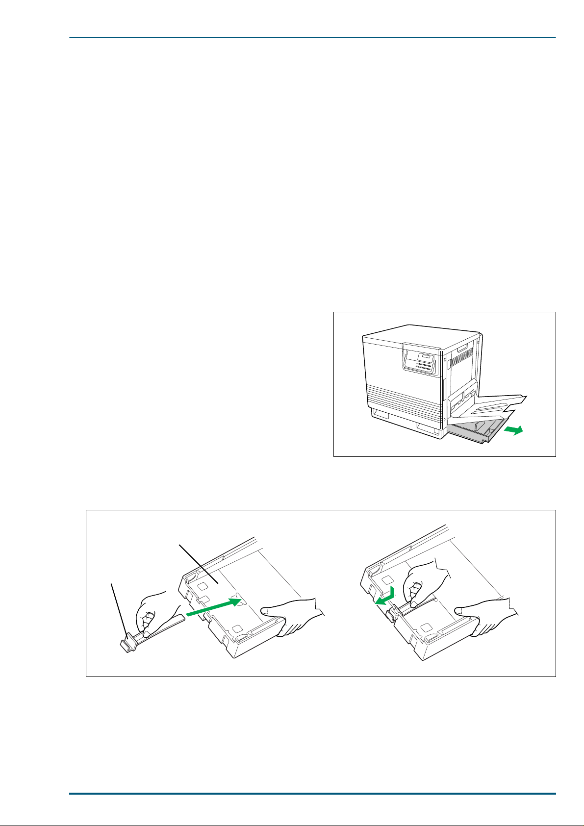
2. Remove the media cassette(s) from the printer;
remove the media from the cassette(s).
3. Press down on a media cassette’s metal plate. Place the plastic shipping lock into the media cassette as
shown.
Metal Plate
Shipping Look
(3)
(1)
(2)
4. Reinsert the media cassette into the printer; use adhesive tape to secure the cassette to the printer.
5. If the other media casse ttes are in sta lle d, repa ck them for s hi pping or st orage in t heir ori gina l ship pi ng
boxes.
21
Page 29
FS-5900C Service Manual
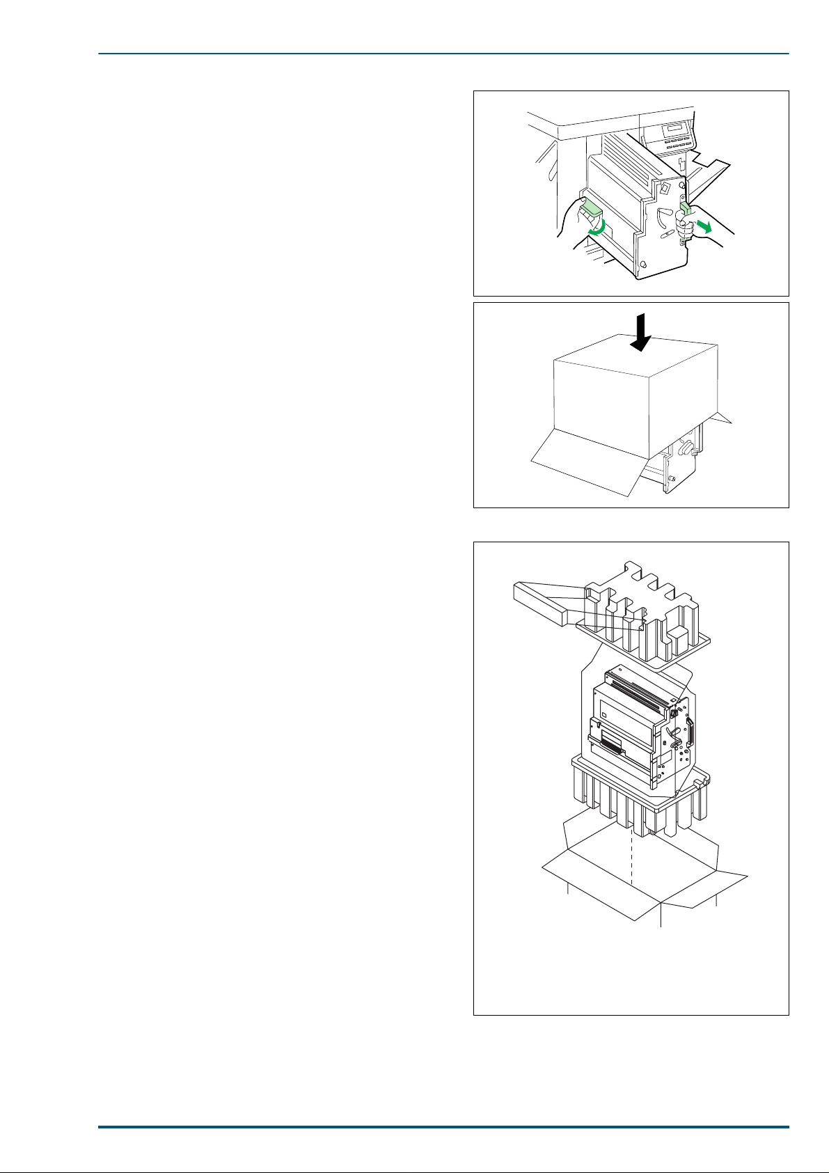
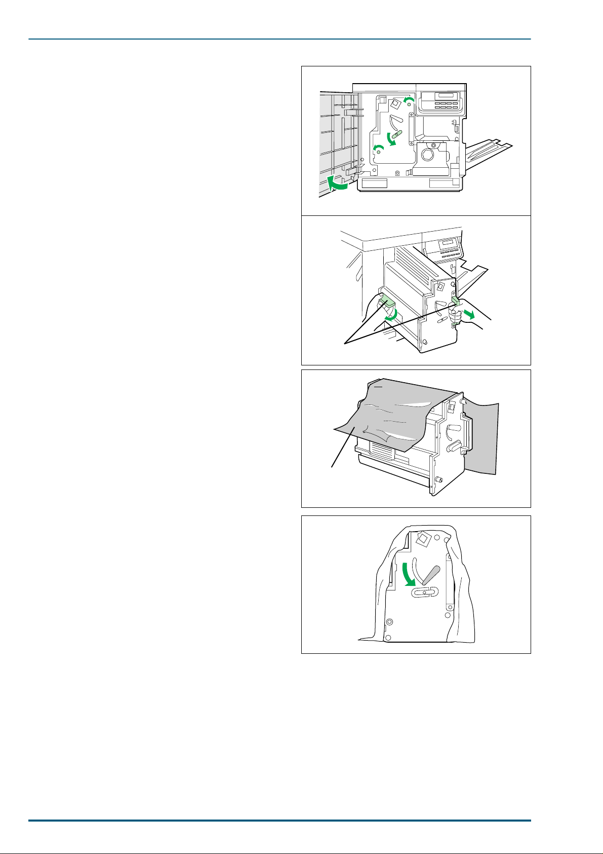
6. Open the printer’s front door. Loosen the two thumb-
screws by turning them counterclockwise. Turn the
lower green lever 180° counterclockwise.
7. Grasping the front green handle, sli de the unit out
until it catches. Lift up the green handle on the left.
Pull the imaging unit out of the printer.
Caution: The imaging unit we igh s app rox imate ly 6.5
kg (14.3 lbs.). Always use the handles when
lifting it.
8. Wrap the imaging unit with a protective black plastic
sheet.
Important:
• Do not touch the green surface. Fingerprints may a ffect
print quality.
• Do not expose the imaging unit to light for more than
45 seconds, or irreversible damage may result.
9. Move the upper lever 90° counterclockwise; this is
necessary to protect the imaging unit during shipment.
Handles
Plastic Sheet
22
Page 30
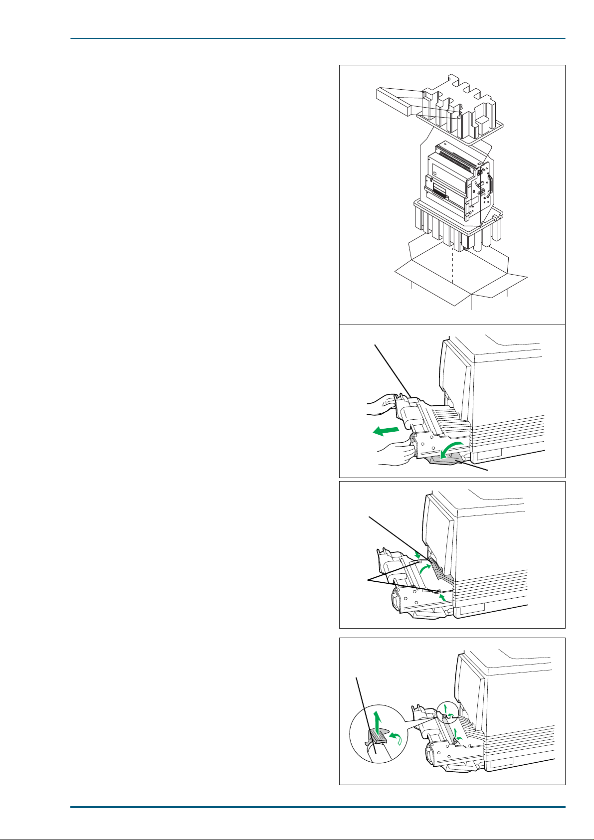
10.Insert the imaging unit into the packaging.
Paper Feeder
Left Side Door
Cover
Tabs
Transfer Roller
2. Installation, Setup, and Repacking
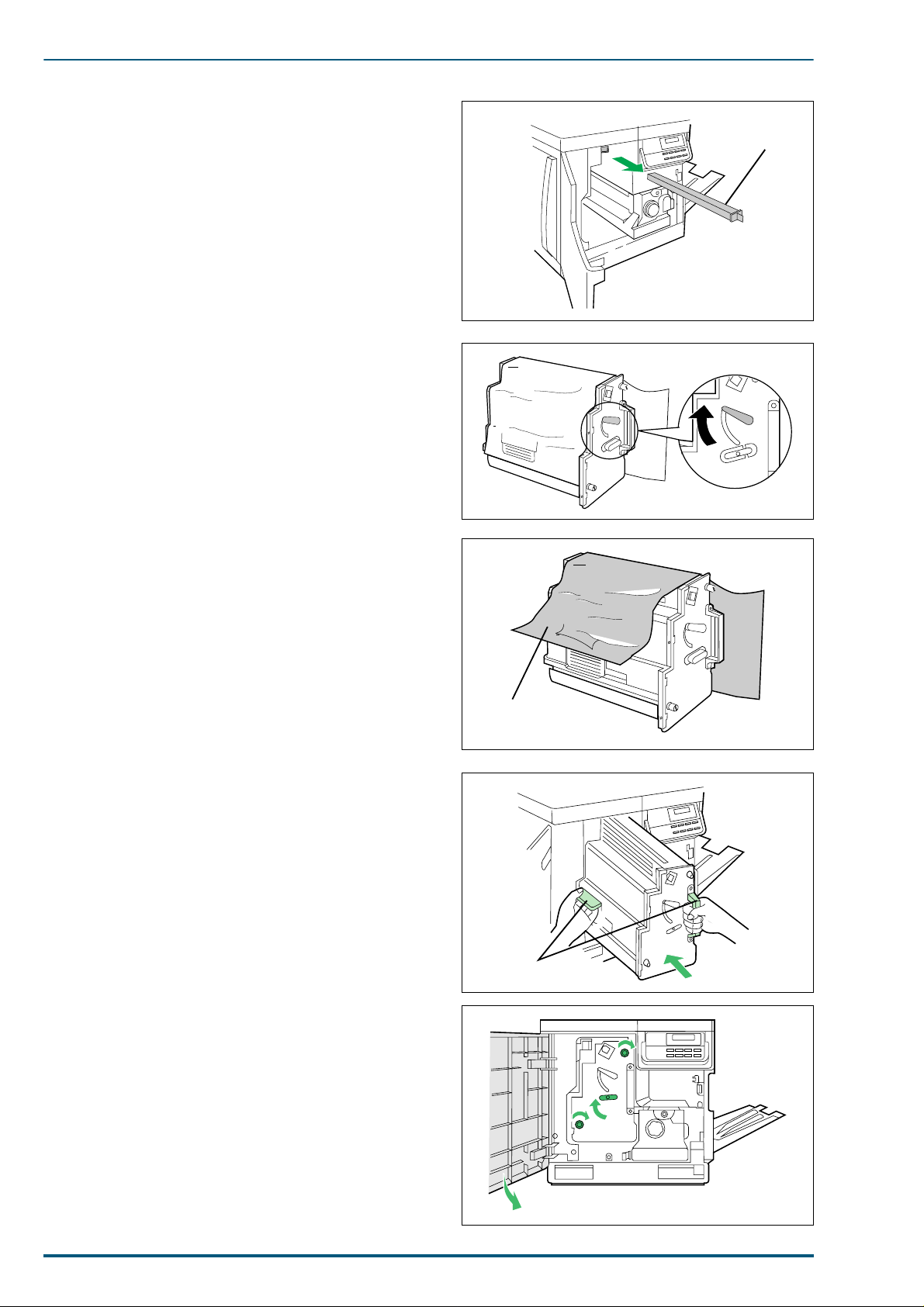
11.Open the left side door. Using the green handles,
slide the paper feeder out.
12.Push in on green tabs to unlock the cover. Raise the
cover until it catches in the open position.
13.Rotate the transfer roller’s green handles up. Lift out
the transfer roller/waste bin.
23
Page 31

FS-5900C Service Manual
14.Rotate the handles down and wrap the transfer unit
with a piece of paper and adhesive tape.
Note: Do not touch or bump the roller as it can damage
the roller.
15. Install the plastic cover and insert the transfer unit
into a plastic bag and seal the end tightly. Install the
transfer unit into the packaging.
Note: Use the plastic cover that is attached to the new
TR-81 transfer unit.
16.Remove the four toner devel opers; install the protec-
tive cover for each developers; repack them for shipping or storage in their original shipping boxes.
Plastic Cover
Plastic Bag
17.Wipe off any loose toner in and around the printer.
Note: If a toner vacuum is available, it is the best tool
for cleaning spilled toner. Do not use a standard
office vacuum; the toner will not be retained by
typical vacuum dust collectors.
18.Close all printer doors and secure them with adhesive tape.
19.Raise the output tray and secure it to the printer
with adhesive tape. If a paper feeder is not installed,
go to Step 21.
20.If a paper feeder is installed:
Lift the printer up and away from the paper feeder.
Safety Caution:
The printer weighs approximately 41.4 kg (91.2 lbs.) and
the paper feeder weighs 14.4 kg (31.5 lbs.). Observe
standard precautions for lifting heavy objects.
24
Page 32

Repack the paper feeder in its origina l shipping box.
21.Repack any other accessories in the original shipping box.
22.Repack the printer in the original shipping box. Make
sure that the printer is upright and level when moving. See the diagram on this page.
2. Installation, Setup, and Repacking
25
Page 33

FS-5900C Service Manual
3. Mode Selection
This section explains the menu levels and options which can be set using the control panel MODE key. The
MODE key can be used to display all of the menus in the following diagram:
Ready
PAR 600 A4 001
MODE
Parallel
Serial
Option
Number of copies
PCL 5C
Emulation >
KPDL
KPDL (AUTO)
Font >
Bitmap
Scalable
Page orientation
Portrait
Landscape
Press the MODE key.
001
>Interface
>Emulation
>Parallel I/F
>Code set
ISO-6 ASCII
>
>Print KPDL errs
Off
*2
)
(
On
>Bitmap font
00001
>
>AudreyTwo-Regular
SWC
>Size
012.00 point (s)
>Pitch
Nibble (high)
High Speed
Normal
Auto
10.00 cpi
(
(*1)
*3
These items will not show unless the
printer is installed with the applicable
option unit/kit.
>Baud rate
9600
>Data bits
8
>Stop bits
1
>Parity
None
>Protocol
DTR (pos.)&XON
>Barcode mode
On
Off
)
*1:
Depending on the emulation selected,
*1
: Depending on the emulation selected,
the following code sets are available.
the following set >code sets are
available.
Opt. ROM >
HARD DISK >
RAM DISK mode >
Continued on next page
>Read data
>List of partitions
>Read data
(*4)
>RAM DISK size
>Read data
>Write data
>Delete data
>Print VMB data Tray:
>List of Partitions
>List of VMB
C5LCP
dnapamtiB
stnoFelbalacS
IICSA6-OSI
nedewS11-OSI
nailatI51-OSI
niapS71-OSI
yawroN06-OSI
ecnarF96-OSI
8-namoRPH
lageLSU
8-CPMBI
058-CPMBI
6nitaLOSI
.K.U4-OSI
8htaM
tnofiP
ynamreG12-OSI
1nitaL49-AMCE
)N/D(8-CPMBI
ISO Latin 9
stnoFelbalacS
ylnO
htamSP
txetSP
gnihsilbupSM
swodniW
tlabniW
potkseD
2nitaLOSI
5nitaLOSI
1nitaLswodniW
2nitaLswodniW
5nitaLswodniW
577-CP
2nitaL258-CP
4001-CP
hsikruT-CP
hsotnicaM
26
Page 34

Continued from previous page
MEMORY CARD > >Read fonts
>Read data
>Write data
>Delete data
>Format
>List of Partitions
3. Mode Selection
Paper handling >
Colour mode >
Colour >
Matching
Colour >
Calibration
>MP tray mode
>MP tray size
>MP tray type
>Duplex mode
>Auto cassette
>Override A4/LT
>Monochrome
>Colour
>Quick Colour
>RGB Simulation
>Vivid mode
>Black
10
>Yellow
10
>Magenta
10
>Cyan
10
>Print Calibration Page
Life counters >
Continued on next page
>Total print
1234567
>TransferRoller >
1234567
>Imaging unit
1234567
>Fuser KIT
1234567
>Oil supply roll
1234567
>Main Charger
1234567
>Cleaning Pad >
1234567
>>Reset Transfer
roller ?
>>Reset Cleaning
Pad ?
27
Page 35

FS-5900C Service Manual
Continued from previous page
Others >
>MSG language
English
>Form Feed
Time out 030sec.
>Sleep timer
060 min
>Print HEX-DUMP
>List of
resident Fonts
>Printer Reset
>LF action
LF only
CR and LF
Ignore LF
>CR action
CR only
CR and LF
Ignore CR
*5
(
(*6)
)
>Ecoprint mode
Off
>Resolution
>Resource prot.
Off
*2:
The printer can be set to print error data
during KPDL em ulation. If thi s is set to 2Q,
error data will be printed if trouble occurs
during printing. This is set to
leaving the factory.
*3:
*4:
*5:
*6:
*7:
6L]H
The >
Courier
3LWFK
>
fonts.
The
played when an optional hard disk unit
is installe d.
Any value from 0 to 495 [seconds] in 5second increments. (The printer does not time out with
the value set to 0.)
Any value from 0 to 120 [minutes] in 5-minute increments.
For service purpose only.
menu is not available for the
LetterGothic
and
menu to scale these fixed
5$0#',6.#PRGH
2II
before
fonts. Use the
menu is not dis-
>Buzzer
Off
>Service >
On
Permanent
Perm / Temp
On
>>Print
Test page 2
>>Print
Test Page 1
>>TransferRoller
? Type X
>>Print
Status Page
(*7)
28
Page 36

3. Mode Selection
3.1 Nav igating through the Menus
The menus are in the hierarchy as shown in the diagram above. Use the + and – keys to move between
menus in the same level (“vertically” in the table). The + key shows the next menu, while the – key shows
the previous one. Change levels by using the and keys. The key moves to lower levels (sub-menus),
while the key moves to higher levels.
2, 4, 6
3
5, 7
1, 8
To make change to a specific item, for example, the sleep mode timeout time, proceed as follows :
1. Press the MODE key.
The message display will show one of the first level menus (Level 1 in the table on pages 25 and 26)
depending on the previous selection.
2. Press + until Others > is shown on the display.
3. Press .
The message display will show one of the second level menus (Level 2 in the table on pages 25 and 26)
belonging to the Others menu above depending on the previous selection.
4. Press + until Sleep timer is shown on the display.
5. To change the timeout value, press ENTER.
If you want to abandon setting, press CANCEL, then press MODE.
6. Press + repeatedly to increase the timeout time; press – repeatedly to decrease the timeout time until
the desired timeout time (in minutes) is displayed.
7. Press ENTER to confirm the new setting.
You can abandon the new setting by pressing CANCEL, then MODE.
8. To quit the mode selection sequence, press EXIT.
3.1.1 Display Information
Life Counters
Section menu Description
Imaging unit
Transfer Roller
Fuser Kit
Oil supply roll
Total print
A count of the total number of images fed since the Imaging unit was last replaced.
A count of the total number of pages fed since the Transfer Roller was last replaced.
A count of the total number of pages fed since the Fuser Kit was last replaced.
A count of the total number of pages fed since th e Oil supply roll was las t replaced.
A count of the total number of pages fed since the product is shipped.
29
Page 37

FS-5900C Service Manual
4. Mechanical Functions
4.1 Drive Mechanism/Image Process General Description
Drive Mechanism
Eight DC servomotors are used to transmit drive to each mechanical block within the engine. The main
motor transmits drive to the imaging unit. The paper feed motor transmits drive to the paper feed unit,
fuser unit and toner developer selector/paper eject unit. The toner developer motor transmits drive to the
toner developers. Four cam motors in the toner developer selector/paper eject unit mov e the toner develop er
to their development position. The MP tray paper feed motor in the paper feed unit is the stepping motor
and feeds the paper in the multi-purpose tray.
The paper feed unit, laser scanning unit, toner developers, fuser unit and toner developer selector/paper
eject unit are designed for easy removal from the printer for ea sy maintenance.
Print Process
The laser printer creates an image on paper using a technique called laser electrophotography. The printer
uses the electrog raphic process known as t he disc harged are a deve lopment, or write bla ck. In this process, a
digitally modulated laser scans laterally across a rotating OPC belt that has been negatively charged.
Wherever the belt is exposed by the laser beam, the image is written and toner is transferred.
To generate a color image, the OPC belt must complete four rotations, one for each primary color and black.
During each successive pass, the laser exposes the portions of belt that correspond to the primary color’s
component of the image. Toner is attracted to the laser-exposed portions of the belt.
As each color layer is developed on the OPC belt, they are transferred to the accumulator belt until all four
color layers eventually reside one on top of the o ther on the accumulator belt . At this point, a sheet of pap er
is advanced under the accumulator belt and the toner is transferred to the sheet of paper. The paper
advances to the fuser, where heat and pressure permanently bond the toner to the paper. From the fuser,
the paper is driven to the output tray.
A cleaning blade scrapes residual toner from the OPC belt before the next primary color toner is applied to
the belt. This prevents contamination of the next color layer. The cleaning blade is in constant contact with
the belt. An accumulator belt cleaner scapes residual toner from the accumulator belt. This preve nts “ghosting” of the next print. The blade only comes in contact with the belt after the accumulated toner layers are
transferred to the sheet of paper.
Drive Unit Layo u t
Toner Developer Selector/
Paper-eject Unit
Cam Motor
Laser Scanning Unit (LSU)
Imaging Unit
30
Main Motor
Paper Feed Unit
MP Tray Paper Feed Motor Paper Feed Motor
Toner Developer
Toner Developer
Drive Motor
Fuser Unit
Page 38

Print Process
4. Mechanical Functions
2
Laser Scanning Unit (LSU)
Multipurpose
Tray Pickup
Roller
5
Intermediate
Rollers
Pickup
Roller
Transfer Roller
(+300 V)
1
Erase Lamp
OPC Belt
Cleanning Blade
OPC Belt Cleaner
4
First Bias
Transfer
Roller
Accumulator
Belt
Registration
Rollers
Scorotron Charger
+500 ~ 700 v
6
Waste
Toner
Bin
Cleaning
Roller
(+500 to 2600,
depending on
media and
humidity)
Second Bias
Transfer
Roller
OPC Belt
Accumulator
Belt Cleanning Blade
On-Off
Supply
Roller
Toner Cartridges
Black
Cyan
Magenta
Yellow
Pre-Transfer Lamp
Fuser
3
Toner Cartridge
Selector Cam
Take-up Roller
Heated Roller
Pressure
Roller
7
Each block is explained in the following sections:
1. 4.2.1 Discharge and Charging
2. 4.2.2 Laser Exposure and Scanning
3. 4.2.3 Developing
4. 4.2.4 Toner Transfer to the Accumulator Belt
5. 4.2.5 Paper Pickup
6. 4.2.6 Toner Transfer to Paper
7. 4.2.7 Fusing and Exiting
31
Page 39

FS-5900C Service Manual
OPC Belt
Laser Beam from LSU
4.2 Print Process
4.2.1 Discharging and Charging
Discharge
The print process begins when the OPC belt passes by
the erase lamp. The belt is rotating at 100 mm-per-second for 600 dpi printing or 53 mm-per-second for 1200
dpi printing. The light of the erase lamp, which is a horizontal row of red LEDs, removes random negative
charges from the OPC belt. Before pre-exposure, the surface of the belt varies from -500 volts to +50 volts. After
pre-exposure, the surface of the belts is 0 to -20 volts.
The pre-erase lamp is called the erase lamp since it
erases negative charges from the belt.
Charge
The electrostatic potential of the belt is not uniform following discharging. As the belt rotates, it passes a scorotron charger, which bombards the belt with negative
charges. The scorotron charger behaves somewhat like a
vacuum tube. The grid of the charger, held at a potential
of between -450 volts to -600 volts and coupled with the
varying voltage potential on any discrete point on the
belt’s surface, determines how many electrons can flow
from the corona wire onto that point of the belt’ s surface.
The corona wire is charged to -5 kilovolts with a constant
current of -400µA. The varying electron output from the
scorotron, directly based on the varying charge of the belt
surface, ensures a uniform negative potential of -440
volts or -590 volts on the belt surface, depending on the
selected dot-per-inch printing and ambient temperature.
Erase Lamp
Scorotron
Charger
Tungsten Wire
OPC Belt
Grid -450 ~ -600v
-5kv
4.2.2 Laser Exposure and Scanning
Laser Exposure
As the OPC belt rotates, the uniformly charged belt is
exposed by the modulated laser beam. The verticallymoving belt passes in front of the horizontall y scanning
laser beam, and negative charges on the belt surface are
neutralized by the beam. This forms a latent image.
Laser output power is either 0.26 mW or 0.33 mW,
depending on whether the printer is printing in 1200
dots per inch (dpi) mode or 600 dpi mode. The laser exposure, the negative potential on the belt varies from -440
volts or -590 volts (unexposed) to -10 or -20 volts (fully
exposed).
32
Page 40

4. Mechanical Functions
Laser Scanning
A laser diode generates the laser beam, and lenses and mirrors in the laser scanner direct the beam at the
photoconductive belt. The beam is made parallel by the collimator lens and is directed at the rotating polygonal mirror. The mirror rotates at a constant 25,197 revolutions per minute. This transforms the beam into
a horizontally scanning beam, which is directed through the f-θ primary lens, altering the beam’s angular
rotation motion into a constant horizontal motion. The toric correction lens corrects the beam for any vertical misregistration. Next, the beam reflects off of a mirror and passes through a window where it scans
across the rotating photoconductive belt. At the beginning of e ach horizontal sweep, the horizon tal sync mirror deflects the laser beam to the horizontal sync sensor. This informs the engine control board that the
laser beam is beginning its horizontal sweep and that it can begin to modulate the signal with the data to be
printed on that line of the image.
Laser Diode
Collimator Lens
Horizontal-Sync Mirror
Polygon Mirror
Fθ Lens
Horizontal-Sync Sensor
Mirror
Fθ Lens
33
Page 41

FS-5900C Service Manual
4.2.3 Developing
Developing
As the OPC belt co nti nue s t o ro ta te, i t pa sse s b y the fou r
toner developers. Each cartridge is selectively camdriven forward to bring its developer roller into direct
contact with the belt at the appropriate time.
The currently activated toner developer’s developer
roller is charged to a potential between -120 to -260 volts.
Toner is attracted to the exposed portions of the belt in
reverse proportion to the negative charge. The greatest
amount of toner is transferred to the most positive potential. The developer roller rotates at 1.8 (600 dpi printi ng)
or 2.13 (1200 dpi printing) times the speed of the OPC
belt to ensure a constant supply of toner.
OPC Belt
Developer Roller
(-120 to -260v)
Doctor Blade
Supply
Roller
Paddles
Black
Cyan
Magenta
As the belt advances, it passes the pre-transfer lamp,
Yellow
which, like the discharge lamp, removes remaining negative charges from the unexposed portions of the belt.
Inside each toner developer is a toner supply roller that
rotates in the opposite direction from the developer
roller. This supplies a layer of toner onto the developer
Pre-transfer
Lamp
Toner Cartridges
Cartridge Selector Cam
roller. The doctor blade smooths and evenly distributes
the toner on the developer roller. Gear-driven paddles
churn the toner and keep it fluidized and moving
towards the developer roller.
Toner Developer Drive
Drive is supplied from the toner developer drive motor. At the proper time, the clutch corresponding with
the currently selected toner developer is activated by a signal from the CPU, transmitting drive to the
clutch gear via idle gears. Drive is then transmitted to the developer rollers.
The toner level sensing receiver board detects whether each of the four toner developers contains sufficient
toner. This board is paired with the toner level sensing transmitter board and functions as the photo sensors.
Toner Developer Drive Motor
Clutch Gear
Developer Roller
Black
34
Clutch Gear
Developer Roller
Clutch Gear
Developer Roller
Clutch Gear
Developer Ro ller
Cyan
Magenta
Yellow
Toner Developers
Page 42

4.2.4 Toner Transfer to the Accumulator Belt
OPC BeltCleaning Blade
OPC Belt
+500 to 700v
Accumulator
Belt Home
Sensor
First Bias
Transfer
Roller
Accumulator
Belt
Multipurpose
Tray Pickup
Roller
Registration
Roller
Registration
Sensor
Intermediate
Rollers
Pickup Rollers
MP Tray Paper
Out Sensor
MP Tray Paper
Feed Motor
Paper Empty
Sensor
Paper Cassette Sensor
Terminal for detecting
paper cassette
As the OPC belt rotates, it comes in contact with the
accumulator belt, which is rotating at the same speed.
Located under the accumulator belt at the contact point
with the OPC belt, the first bias transfer roller carries a
charge that varies between +500 and +700 volts (based
on the sensed temperature, humidity and print speed).
This strong potential attracts and holds the toner from
the OPC belt to the accumulator belt. The accumulator
belt makes four complete rotations, one for each of the
four toner layers. The accumulator belt home-position
sensor sync signal, generated from a timing mark on the
accumulator belt, informs the engine control board when
to begin expo sin g t he O P C be lt wi th informati on t o b ui ld
the next tone r lay er. At that time, the acc umula tor bel t is
rotated to the proper position to transfer the toner layer
in proper registration with the previous layer(s).
Any toner remaining on the OP C belt after the transfer
to the accumulator belt is scraped off by the OPC belt
cleaning blade, which is always in contact with the belt.
This leaves the OPC bel t cl ean f or t he next la yer of to ner
to be transferred from the toner developers.
4. Mechanical Functions
4.2.5 Paper Pickup
The cam-shaped pickup rollers are driven by the paperfeed motor and force a sheet of pape r between the intermediate rollers. The pickup roller completes only one
rotation to pick a sh eet of media . This will push the s heet
of paper to the intermediate rollers but does not pick a
second sheet. Alternately, depending on the user’s selection, media may be picked from the multi-purpose tr ay.
The multi-purpose tray pickup roller is driven by the
M.P.T paper feed motor and feeds a sheet of media or an
envelope into the registration rollers.
The intermediate rollers advance the sheet of paper to
the registration rollers. The paper is driven lightly
against the stationary registration rollers to create a
slight buckle in the paper, aligning the sheet of paper. At
this point, the paper remains stationary (since the registration roller’s clutch is not yet energized) until the
image is ready to be printed on the paper. The registration sensor detects whether the sheet of paper arrived at
the aligning rollers after being p roperly picked and
traveling through the intermediate rollers.
The paper feed unit has the MP tray paper out sensor,
paper empty sensor and paper cassette sensor. The MP
tray paper out sensor detects whet her the paper i s set on
the manual feed tray. The paper empty sensor detects
whether the paper is set i n the paper cass ette. The paper
cassette sensor detects paper cassette presence and
paper size.
35
Page 43

FS-5900C Service Manual
4.2.6 Toner Transfer to Paper
Once all four layers of toner reside up on the accumulator belt, the registration roller clutch is energized to
advance a sheet of paper (which has alre ady been picked)
to the second bias tra ns fer rolle r. The toner image on the
rotating accumulator and the paper that is being fed into
the image unit are synchronized for proper alignment.
The leading edge of the toner image on the accumulator
belt is aligned 5 mm from the leading edge of the paper.
A strong positive voltage in the second bias transfer
roller attracts the toner from the accumulator belt to the
paper. The transfer roller voltage varies from +500 to
+2600 volts based on the ambient temperature, humidity,
print speed and media being prin ted upon. T he p aper (o r
transparency film) advances at the same speed as the
accumulator belt.
As the toner is being transferred to the paper, the accumulator belt cleaning blade is activated. This blade
scrapes any remaining traces of toner from the accumulator belt prior to the next image transfer. Residual toner
is removed from the second bias transfer roller by a
cleaning roller that is held at a potential that is +300v
higher than the second bias transfer roller. A blade
scrapes the toner off the cleaning roller into the toner
waste bin.
Second Bias
Transfer Roller
Cleaning
Roller (+300 V
higher than
STR)
Accumulator Belt
Cleaning Blade
+500 to 2600 V
Waste
Toner
Bin
4.2.7 Fusing and Exiting
Fusing
After the toner image has been applied to the paper, it passes through the fuser. A heated roller melts the
toner and pressure drives it into the paper. The melted toner bonds to the paper. An oil supply keeps the
heated roller lubricated so that the melted toner does not adhere to the roller. After fusing, the paper
advances to the output tray. When the printer is idle, the heated roller is held at a temperature of 150 °C.
The heated roller is set to 156 °C for 600 dpi printing and 137 °C for 1200 dpi printing. For transparency
film and other media the fuser is set to 160 °C and ran at h al f speed. The paper ejection s ensor detects the
sheet of paper as it leaves the fuser.
Take-Up
Roller
Supply
Roller
Heated
Roller
Fuser Roll
Oil (soaked)
Pressure
Roller
36
Fuser
Page 44

4. Mechanical Functions
Reverser
The reverser allows
the prints to exit to
the exit tray printed
side down
Output Tray
Paper Full
Sensor
Paper Exit
Sensor
Output
Tray
Paper Ejection
Sensor
Fuser
Switchback
Support Roller
Switchback
Roller
Switchback
Support
Roller
Paper ejection
roller #1
Switchback
Gate
Switchback
Roller Shaft
Switchback
Solenoid
Paper Path
Eject
If face up eject is selected, the paper goes directly to the output tray unde r the switchback gate, printed side
up.
Paper Ejection
Sensor
Output Tray
Paper Full Sensor
Paper Path
Paper Exit
Sensor
Output
Tray
Fuser
Or, if face down eject is selected, the switchback
solenoid on the toner developer selector/paper eject
unit is activated to ho ld th e s w itc hb ac k ga te in th e
down position, allowing the paper to be fed to the
reverser, which drives the sheet up a narrow channel. At this time, the switchback shaft linked with
the switchback gate moves to posi tion A. At the
proper time, the switchback solenoid is turned off,
which returns the switchback gate to the up position. Also, the switchback shaft moves to position
B. These movements reverse direction and routes
the sheet of paper to the output tray printed side
down. This is appropriate for a collated series of
prints that need to remain in first-to-last order.
The paper exit sensor detects the sheet of paper as
it enters the exit rollers.
Switchback Gate
Position A
Switchback
Gate
Switchback
Shaft
Paper
Position B
Paper Path
Paper ejection roller #2
37
Page 45

FS-5900C Service Manual
5. Removal and Replacement Procedures
Caution:
The imaging unit (OPC belt and accumulator belt) is extremely light sensitive. Make sure that
it is not exposed to li ght fo r more than 45 seconds , or it may da mage t he unit. Ne ver expose the
imaging unit to direct sunlight. When servicing the printer, ensure that the imaging unit is not
exposed to light. If necessary, remove it and store in a dark place.
5.1 Upper Rear, Lower Rear and Top Covers
1. Remove the upper rear cover (4 screws).
2. Remove the lower rear cover (4 screws).
3. Separate the lower rear cover from the duct tube.
4. Remove the top cover (3 screws).
The front of the top cover is held by metal tabs.
Tilt the top cover up from the rear (arrow 1), slide it
back slightly (arrow 2), and remove it.
Screw
Fan
Cover
Screw
Upper Rear
Cover
Top Cover
~
A
C
I
N
Opening on
Chassis Frame
Metal Tab
2
1
5.2 Left Side Cover and Multi-purpose Tray
1. Remove the upper rear cover and top cover (See sec-
tion 5.1).
2. Open the left side cover.
3. Pull out the paper feed unit.
4. Lower the MP tray.
5. Remove the left side cover while releasing the 4
hooks from the printer f rame.
6. Remove the multi-purpose tray by sliding part A in
the direction indicated by the arrow.
Screw
Board
Fan
Cover
Left Side Cover
Part A
Multi-purpose Tray
Paper Feed Unit
Duct tube
Humidity
Sensor Case
Lower Rear Cover
Hook
Left Side
Cover
38
Page 46

7. Turn the bushing 90 degrees counterclockwise.
Tab
Bushing
Bushing
Bushing
Rack
Paper
Support
Rack
Pinion Gear
Operation
Panel Cove r
Screw
Connector
Screws
Earth
Lead
Board
8. Remove the 2 bushings.
9. Separate the paper support assembly from the
holder.
10.Remove the pinion gear and racks (3 screws).
5. Removal and Replacement Procedures
Turn the bushing 90
degrees clockwis e or
counterclockwise.
5.3 Operation Panel Cover and Printer LCD Board
1. Remove the upper rear cover and top cover (See
section 5.1).
2. If the imaging unit is installed, remove it.
3. Open the front cover and remove the operation
panel cover assembly (3 screws).
4. Remove the 1 earth lead wires (1 screws).
5. Disconnect the connector.
39
Page 47

FS-5900C Service Manual
6. Remove the LCD board bracket (4
screws).
7. Remove the LCD board (6 screws).
8. Remove the operation button from the
operation panel cover.
9. Remove the lower operation panel cover
(2 screws).
Lower Operation
Panel Cover
Ground
Wire
LCD Board
Operation Button
Operation Panel Cover
Screw
5.4 Safety Interlock Switches and Toner Empty Sensor Board (T)
1. Remove the upper rear cover, top cover and operation panel cover (See section 5.1 and 5.3).
2. Remove the 3 screws and disconnect the connector on the toner empty sensor board.
3. Remove the toner empty sensor board.
4. Disconnect the 2 connectors from each of the 2 safety interlock switches.
5. Remove the 2 screws from each of the 2 safety interlock switches.
6. Remove the screw from each of the switch levers and switch lever.
Connector
Screw
Toner Empty
Sensor Board
Screw
Switch Lever
Safety Interlock Switch
Screw
Connector
Screw
Connector
Switch Lever
40
Screws
Connector
Screw
Safety Inter lo c k Switch
Page 48

5. Removal and Replacement Procedures
Parts C
5.5 Front Cover and Bottom Front Cover
1. Open the front cover.
2. Remove the bottom front cover (3 screws).
3. Remove the front cover with hinges [4 screws (A)].
4. Remove the hinge assemblies from the front cover [4 screws (B)].
5. Remove the E-rings f rom the hinge shafts. The front cover hinges can now be separated from the front
cover hinge supporters.
Note:
E-ring
Hinge Shaft
E-ring
Screw (A)
E-ring
Hinge Shaft
E-ring
Screw (A)
Front Cover Hinge
Screw (B)
Front Cover
Hinge Supporter
Screw (B)
Front Cover
Hinge Supporter
Front Cover
The bottom front cover is latched by metal tabs
(Parts C below). When removing or reinstalling
this cover, it must be released from the tabs or
latched with the tabs.
Screw
Bottom
Front Cover
41
Page 49

FS-5900C Service Manual
5.6 Front Right Side, Rear Right Side and Lower Right Side Covers
1. Remove the bottom front cover (See section 5.5).
2. Remove the paper exit tray.
3. Remove the front right side cover (2 screws).
4. Remove the rear right side cover (2 screws).
5. Remove the lower right side cover (2 screws).
Rear Right Side Cover
Screw
Screws
Front Right Side Cover
Note:
The lower right side cover is latched by metal
tabs (Parts A below). When removing or reinstalling this cover, it must be released from the tabs or
latched with the tabs.
Lower Right Side Cover
Screws
Paper Exit Tray
Parts A
42
Page 50

5.7 Left Side Cover
Left Side Cover
5.7.1 Left Side Cover Removal
1. Open the left side cover.
2. Remove the black strap by releasing the hooks.
3. Remove the left side cover by sliding it in the direc-
tion of arrows 1, 2.
5. Removal and Replacement Procedures
Hook
Strap
Hook
2
1
Left Side Cover
Spring
5.7.2 Left Side Cover Sub Assembly
1. Remove the tray cover by sliding it in direction of arrow while slightly deflecting part (A) of left side
cover in the direction of arrow. Release the tray cover from the tab on the left side cover as shown in circle A below.
2. Remove the paper chute (2 screws).
3. Remove the tray cover lever (1 screw).
4. Remove the 2 E-rings and 2 door hooks.
5. Remove the left side cover shaft and shaft spring by pulling out the door shaft.
When reinstalling the tray
cover and the tray spring,
Tray SpringTray Cover
AAAA
Tray Cover Lever
Left Side Cover
Tab
E-ring
install the spring as shown
below.
Tray Cover Tray Spring
Tray Cover
Part (A)
E-ring
Left Side Cover Shaft
Door Hook
Paper Chute
Door Hook
Shaft Spring
Screw
43
Page 51

FS-5900C Service Manual
5.8 Printer Main Control Board, HSYNC Board and Network Relay Board
5.8.1 Printer Main Board Removal
1. Remove the cable cover (2 screws).
2. Disconnect the connector by pulling the tab.
3. Remove the 2 screws, then pull out the printer main
board.
Note:
When replacing the printer main board, the current EEPROM (IC9) must be installed on the new
board. If the EEPROM is damaged, the color density calibration must be reset. Refer to section
7.2.
Screws
Pull out
Printer Main
Control Board
5.8.2 Printer Main Control Board Disassembly , HSYNC Board and Network Relay
Board
1. Remove the 3 screws from the connectors.
2. Separate the main board bracket from the printer main control board.
Main Control Board
Main Board Bracket
Screw
Screws
44
Page 52

5. Removal and Replacement Procedures
Screw
Green Handle
Green Handle
Screw
Tabs
Square Opening
Paper Feed
Unit Cover
5.9 Paper Feed Unit
5.9.1 Paper Feed Unit Removal
1. Open the left side cover to access the paper feed unit.
2. Slide out the paper feed until it stops.
3. Push in on the tw o green tabs to unlock the paper
chute. Lift the paper chute until it catches, in the
open position.
4. Rotate the green handles on the transfer roller. Lift
out the transfer roller/waste bin (consumable) to
avoid toner spillage.
5. Remove the 2 screws.
6. Slide the paper feed unit off the rails.
5.9.2 Paper Feed Unit Board and MP Tray Paper Out/Registration Sensor Board
1. Remove the screw from t he paper feed unit
cover.
2. Remove the paper feed unit cover while releas-
ing the 3 hooks.
3. Remove the paper feed unit board (1 screw).
Registration Roller Clutch
Connector
3 Hooks
4. Disconnect the 4 connectors on the paper feed
Note:
unit board.
When reinstalling the paper feed unit
cover, the tabs of the registration roller clutch
must be aligned with the square opening.
Paper Feed
Unit Board
Paper Feed Unit
Cover Screw
Screws
45
Page 53

FS-5900C Service Manual
5. Remove the s e nsor case with the sensors after releas-
ing the 5 hooks in order
screwdriver below.
Flat Blade
Screwdriver
The MP tray paper out sensor, registration sensor and
MP tray Paper Out/reg. Sensor Board can now be
removed from the sensor case by releasing it from the
hooks.
1 to 5 using a flat blade
Opening of
Sensor Cover
Sensor Cover
Hook
Sensor Case
Sensor Case
Sensor Board
Connector
Registration Sensor Arm
MP Tray Paper Out
Sensor Arm
5.9.3 Transfer Roller Clutch, Transfer Roller Holder, Cleanin g Roller Holder and
Registration Roller
1. Pivot the paper chute to an upright position.
2. Lift and remove the paper chute.
Bushing
46
Paper Chute
Bushing
Page 54

5. Removal and Replacement Procedures
3. Remove the 3 E-rings and 2 springs from
the transfer roller cam shaft.
4. Remove the clutch, 2 bushings and
transfer roller cam shaft.
5. Remove the E-ring and gear from the
transfer roller holder shaft.
6. Remove the 2 E-rings, then slide out the
transfer roller holder shaft. The right
and left transfer holders can be removed.
Transfer Roller
Cam Shaft
E-ring
Bushing
Spring
Transfer Roller Holder
E-ring
Bushing
E-ring
Pickup Rollet
Clutch
E-ring
Pickup Rollet
7. Release the 2 springs from the spring
studs (located on back side of the paper
feed unit).
8. Rotate the cleaning roller holder up.
9. Lift and remove the cleaning roller
holder. The cleaning pressure roller and
2 bushings can be removed from the
holder.
Spring
Pull up
Cleaning Roller Holder
Stud
Gear
Pickup Rollet
Transfer Roller
Holder Shaft
E-ring
Pull up
Direction of
Rotation
Spring
47
Page 55

FS-5900C Service Manual
10.Remove the 2 springs and the plastic
clip.
11.Move the upper registration roller to the
right and remove.
12.Remove the 4 E-rings, 2 bushings and
registration roller clutch.
13.Remove the lower registration roller.
Upper Registration
Roller
E-ring
Springs
Plastic Clip
Bushing
E-rings
Bushing
5.9.4 MP Tray Retard Pad
Open the MP tray chute assembly with the
retard pad by sliding it in the direction o f
arrow A.
Remove the retard pad by releasing the
hooks.
Lower Registration Roller
Arrow A
Registration Roller Clutch
MP Tray Chute Assembly
Spring
E-ring
Hook
48
MP Tray Chute Assembly
Retard Pad
Page 56

5. Removal and Replacement Procedures
Hook
MP Tray Pickup Roller
Pickup Roller
Guide
5.9.5 MP Tray Motor, MP Tray Pickup Roller and MP Tray Pickup Roller Shaft
Note:
When reinstalling the pickup roller and cam to the MP tray pickup roller shaft, the rubber side of
the MP tray pickup roller, cams and STR sensor arm must be positioned as shown below.
Cams
5.9.5.1 MP Tray Pickup Roller
Release the hook of the pickup roller guide roller
1.
from the MP tray pickup roller shaft.
2. Remove the E-ring and slide the pickup guide
roller in the direction indicated by the arrow.
Pickup Roller Rubber
STR Sensor Arm
3. Remove the MP tray pickup roller.
49
Page 57

FS-5900C Service Manual
5.9.5.2
Remove the motor bracket with the motor (2
1.
screws).
MP Tray
Motor and
MP Tray
Pickup Roller Shaft
2. Remove the 2 gears and STR sensor arm after
releasing the hooks.
3. Remove the 3 E-rings and 2 bushings from the
shaft.
4. Release the hooks of the pickup roller guide roll-
ers.
5. Move the pickup roller guide rollers and MP tray
pickup roller in the direction of the arrow.
E-ring
STR Sensor
Arm
Bushing
Screw
Gears
Screw
Bracket
E-ring
Bushing
6. Remove the MP tray pickup roller shaft assembly
by sliding it in the order of the arrows
(If necessary, remove the M.P.T pickup roller.)
1 to 2.
E-ring
Pickup Roller Guide
Rollers and Pickup
Roller
MP Tray Pickup
Roller Shaft
50
Page 58

5. Removal and Replacement Procedures
5.9.6 Pickup Roller, Pickup Roller Shaft Assembly and Paper Empty Sensor Arm
Note:
When reinstalling the pickup roller to the pickup roller shaft assembly with the clutch, the rubber
side of both pickup rollers, the pawl on the clutch, and part A of the pickup roller shaft must be positioned as shown below.
Pawl
1. Place the unit face down.
2. Remove the E-ring, then remove the pickup
roller by sliding it in the direction of the arrow.
Pickup Roller Rubber
Part A (D-shape)
E-ring
E-ring
3. Remove the E-ring and pickup roller shaft
assembly. If necessary, remove the pickup rollers.
4. Remove the paper empty sensor arm.
Paper Empty
Sensor Arm
Pickup Roller Shaft A ssemb ly
with Pickup Rollers
Pickup Rollers
Bushing
E-ring
51
Page 59

FS-5900C Service Manual
5.9.7 Paper Feed Roller and Paper Feed Unit Frame
Remove the following parts:
a. Paper Feed Unit Cover, Paper Feed Unit Board, Sensor Case (See section 5.9.2):
b. Transfer Roller Cam Shaft, Transfer Roller Holder Shaft, Cleaning
Roller Holder and Registration Roller (See section 5.9.3):
c. MP tray Motor and MP tray Pickup Roller Shaft (See section 5.9.5):
d. Pickup Roller Shaft and Paper Empty Sensor Arm (See section 5.9.6):
1. Remove the E-ring and gear from the
gear shaft.
E-ring
2. Remove the 3 E-rings, gear and 2 bush-
ings from the paper feed roller shaft.
3. Remove the 4 screws from the paper feed
unit frame.
4. Remove the paper feed unit frame from
the paper feed unit base.
5. Remove the paper feed rolle r from the
paper feed unit base.
6. Remove the spring and MP tray chute assem-
bly.
Bushing Paper Feed Unit Base
Gear Shaft
Roller Shaft
Spring
Paper Feed Unit Frame
Gear
E-ring
Bushing
Gear
Screws
Paper Feed Roller
MP Tray Chute Assembly
E-rings
7. Remove the 2 springs from the MP tray chute
assembly.
8. Remove the pinch roller assembly while dis-
torting the area (A) of the MP tra y Chute using
the (-) driver.
Spring
MP Tray Chute Asse mbly
Area (A)
Pinch Roller
Assembly
(–) Driver
52
Page 60

5. Removal and Replacement Procedures
E-rings
E-rings
Connector
90 to 130 mm
Toner Developer
Selector/Paper-eject
Unit
Spring
Spring
Stoppers
Spring
E-ring
Bushing
E-ring
Bushing
Support
Shaft
5.10 Tone r Developer Selector/Paper-eject Unit
5.10.1 Toner Developer Selector/Paper-eject Unit Removal
1. Remove the paper exit tray, front right side cover,
lower right side cover, rear right side cover, bottom
front cover (See section 5.5 and 5.6).
2. Remove the 4 E-rings and disconnect the connector.
3. To relive spring tension open the toner developer
selector/paper-eject unit.
4. Slide the spring stoppers and springs in the direction
of the arrows to unlatch the springs from the printer
frame.
5. Close the unit.
6. Remove the 2 E-rings and 2 bushings.
7. Slide the support shaft to the right or left, and
remove the unit.
Note:
When reinstalling the toner developer selector/
paper-eject unit, remove the solenoid side cover
and motor side cover from the unit (See section
5.10.2.1). Reinstall the unit on the printer by per-
forming the procedure in reverse order.
53
Page 61

FS-5900C Service Manual
5.10.2 Covers, Sensor Boards (Paper Ejection, Paper Exit, Paper Tray Full) and
Paper Ejection Roller
5.10.2.1 Covers
Remove the spring stopper (right side) and spring (right side).
1.
2. Remove the 12 screws from the motor side cover, solenoid side cover and unit inner cover.
3. Remove the covers, spring stopper (left side) and spring (left side) .
Screw Screw
Unit Inner Cover
Spring Stopper (right side)
Screw
Spring Stopper (left side)
Spring (left side)
Solenoid Side Cover
Spring (right side)
ScrewsMotor Side Cover
4. Remove the unit cover (4 screws).
5. Release the 2 springs from the chassis frames and screw (A), then remove the unit face down cover and
paper tray full sensor arm.
Screw (A)
Spring
Spring
Unit Face Down Cover
Note:
Before reinstalling the unit cover, the unit face down cover should be installed.
54
Unit Cover
Screws
Plastic Wash er
Paper Tray Full Sensor Arm
Screw
Screw
Page 62

5. Removal and Replacement Procedures
5.10.2.2 Sensor Boards (Paper Ejection, Paper Exit, Paper Tray Full) and Paper Ejection
Roller
Sensor Boards (Paper Ejection, Paper Exit, Paper Tray Full)
Disconnect the connector on the paper tray full sensor board.
1.
2. Remove the paper tray ful l sensor board (1 screw).
3. Remove the 2 screws from the paper exit sensor board.
4. Disconnect the 3 connecto rs on t he pa per exit sens or boar d. The paper ex i t sensor b oar d can now be sep-
arated from the toner developer selector/paper-eject unit.
5. Remove the paper ejection sensor board (1 screw).
Paper Exit Sensor Board
Connector
Screws
Paper Ejection Roller
Remove the 2 E-rings and 2 bushings from the paper ejection roller.
1.
2. Remove the paper ejection roller.
Paper Tray Full Sensor Board
Connectors
Paper Ejection Roller
55
Page 63

FS-5900C Service Manual
5.10.3 Cam Motor Board, Toner Developer Movement Sensor Board and Toner
Selector Cam
1. Remove the motor side cover, solenoid side cover and
unit inner cover (See section 5.10.2.1).
2. Disconnect the 2 connectors, then remove the 3
screws from cam motor bracket.
3. Remove the cam motor bracket with the boards.
Connectors
4. Remove the 8 screws from the bracket and 2
screws from the cam motor board.
5. Remove the cam motor board with the motors.
6. Remove the 4 nuts from the 4 cam shafts, then
pull out the 4 cam shafts.
7. Remove the 4 cam gears.
8. Remove the toner developer movement sensor
board (3 screws).
9. Remove the 3 E-rings, gear, plastic
washer and 2 bushings from each shaft.
The toner selector cam and toner selector
shaft can now be removed.
Cam Motor Bracket
with board
Nut
Cam Gear
Cam Shaft
Cam Motor Boar d
E-ring
8 Screws
Screw
Cam Motor Bracket
Screw
Toner Developer
Movement Sensor
Board
Screws
56
Bushing
Toner Selector Cam
Spring Pin
Spring Pin
Bushing
Gear
E-ring
Page 64

5. Removal and Replacement Procedures
Selector Cam
Shaft
Short
Groove
Selector Cam Gear
Long Groove
Pin
Solenoid
Embossments
Direction
of Stroke
Note: When reinstalling the toner selector cam and
toner selector cam gear, make sure that the direction of the pin grooves for the cam and gear are
the same.
5.10.4 Joint Gear and Face Down Switch Back Solenoid
Note: When reinstalling the solenoid, fit the 2 holes of
the solenoid to the positioning embossments, then
tighten the screws while pressing the solenoid to
the arrow direction. This allows minimum stroke
of the solenoid plunger.
1. Remove the motor side cover, solenoid side cover and unit inner cover (See section 5.10.2.1).
2. Remove the E-rings and spring.
3. Remove the joint gear.
4. Remove the 2 screws and face down switch back solenoid.
5. Disconnect the connector on the ADU Jam D sensor board.
Screws
Face Down Switch Back Solenoid
Spring
Joint Gear
Joint Gear Bracket
Gear
E-rings
6. Remove the 2 screws that secure the ADF gate solenoid.
7. Disconnect the connector on the paper tray full sensor board.
57
Page 65

FS-5900C Service Manual
5.10.5 Switch Back Shaft, Switch Back Roller and Face Down Switch Gate
1. Remove the motor side cover, solenoid side cover and unit inner cover (See section 5.10.2.1).
2. Remove the paper ejecti on roller (See sec t ion 5.10.2.2).
3. Remove the cam motor bracket with board and toner selector cam (See section 5.10.3).
4. Remove the cable bracket (2 screws).
5. Remove the E-ring from the switch back shaft.
6. Pull out the switch back shaft.
E-ring
Cable
Bracket
Switch Back Shaft
Pull Out
Switch Back Shaft
7. Remove the joint gear and face down switch back solenoid (See section 5.10.4).
8. Remove the spring, plastic ring and switch back arm.
9. Remove the ADU Gate arm.
10.Remove the 4 E-rings, pin, 2 gears and 2 bushings from the right side chassis frame.
11.Remove the 2 E-rings and 2 bushings from the left side chassis frame.
Bushings
Plastic Ring
Screws
Bushing
E-rings
58
Spring
Switch Back Arm
E-ring
Bushing
Gear
E-ringE-ring
Gear
Pin
Page 66

5. Removal and Replacement Procedures
12.Remove the screw from the paper ejection guide.
13.Slide the paper ejection guide out in the direction of the arrow.
14.Remove the rear frame (2 screws).
15.Remove the 9 screws and 4 E-rings and release the hooks on the frame (A).
16.The switch back roller, face down switch back gate, all chassis frames, etc. can now be separated.
Upper Paper
Ejection Guide
Screws
Rear Frame
Screws
E-ring
E-rings
Shafts
E-ring
Frame (A)
E-ring
Screws
59
Page 67

FS-5900C Service Manual
5.11 Engine Control Board Shield Cover
1. Remove the upper rear cover and top cover. (See section 5.1)
2. Remove the flat cable cover (2 screws).
3. Remove the FG plate (6 screws).
4. Remove the flat cable by disconnecting the cable connectors.
5. Remove 12 screws and the engine control board shield cover.
Screws
Engine Control Board Shield Cover
Screw
Fan Cover
Access Panel (ROM)
Screw
FG Plate
Screw
Note:
When replacing the ROM only, remove the access panel only (3 screws), then replace the ROM.
5.12 Laser Scanning Unit (LSU)
1. Remove the upper rear, lower rear and top covers (See section 5.1).
2. Remove the engine control board shield cover (See section 5.8).
3. Remove the shield cover of the polygen motor (2screw).
4. Disconnect the flat cable.
5. Disconnect the 3 connectors from the LSU.
6. Disconnect the connector CN4 on the engine control board and cut the tie.
7. Remove the LSU (3 screws).
Connector
Screw
Screws
60
Connector CN4
Laser Scanning Unit (LSU)
Page 68

5.13 Power Supply Unit
5.13.1 Power Supply Unit Removal
1. Remove the upper rear cov er and top cover ( See
section 5.1).
2. Remove the engine control board shield cover
and cable cover (See section 5.11).
3. Disconnect the 4 connectors on the power sup-
ply unit and 1 connector (CN30) on the engine
control board.
4. The power supply unit is latched by a metal
tab. Lift the power supply as shown by arrows
1 and 2 and remove.
Connectors
Power Supply
Unit
5. Removal and Replacement Procedures
1
2
Metal Tab
5.13.2 Power Supply Unit Sub Assembly
1. Remove the upper shield cover with fan
(7 screws).
2. Remove the lower shield plate from the
power supply board (6 screws).
Lower Shield
Cover
Screw
Connectors
Power Supply Board
Screw
Fan
Screws
Screws
Upper Shield
Cover
61
Page 69

FS-5900C Service Manual
5.14 Engine Control Board
When replacing the engine control board, the top and the left calibration adjustment are needed. Refer to
Section 8.
1. Remove the upper rear cover and top cover
(See section 5.1).
2. Remove the engine control board shield
cover (See section 5.11).
3. Disconnect all connectors on the engine con-
trol board.
4. Remove the engine control board (6 screws).
Screws
Screw
Engine Control Board
5.15 Fuser/Toner Developer Fan Motor and Ozone Fan Motor
1. Remove the upper rear cover and top cover (See section 5.1).
2. Remove the engine control board shield cover (See section 5.11).
3. Disconnect CN24 on the engine control board.
4. Remove the fuser/toner developer fan motor (2 screws).
5. Disconnect CN23 on the engine control board, and open the clamper.
6. Remove the 2 screws from the fuser/toner developer fan motor bracket.
7. Remove the fuser/toner developer fan motor bracket while releasing the cables from the bracket.
8. Disconnect CN9 and CN12 on the engine control board.
9. Remove the 2 screws and the ozone fan motor.
10.Remove the 2 screws from the ozone fan motor bracket.
11.Remove the duct tube from the fan housing.
12.Remove the ozone fan motor bracket while releasing the cables from the bracket.
62
Bracket
Screw
Fuser/Toner Developer Fan Motor
Screws
Ozone Fan Motor
Screw
Bracket
Screw
Page 70

5. Removal and Replacement Procedures
5.16 Main Motor, Paper Feed Motor and Left Side Cover Switch
1. Remove the upper rear cover and top cover
(See section 5.1).
2. Remove the engine control board shield
cover (See section 5.11).
3. Disconnect CN15 on the engine control
board.
4. Remove the main motor (4 screws).
5. Remove the lower rear cover (4 screws).
6. Disconnect CN22 on the engine control
board.
7. Remove the paper feed motor (4 screws).
8. Remove the left side cover switch cover by
releasing the hooks.
Lower Rear
Cover
Paper Feed
Motor
9. Remove the left side cover switch with the
cable (1 screw).
10.Disconnect the connector CN3 on the engine
control board.
Screws
Duct Tube
Screws
Main Motor
Left Side Cover
Switch
Switch Cover
5.17 Transfer Roller Bias Terminal, FTR Bias Terminal, Home Sensor Board and Fuser Joint Connector
1. Remove the upper rear cover and top cover (See section 5.1).
2. Remove the engine control board shield cover (See section 5.11).
3. Remove the FTR bias terminal unit (2 screws).
4. Disconnect the cable from the FTR bias terminal.
5. Slide out the paper feed unit.
6. Remove the 8 screws that secure the cover plate.
7. Disconnect the cable from the transfer roller bias terminal.
8. Remove the 2 screws. The transfer roller bias terminal is disassembled and can be removed from the
chassis frame.
9. Disconnect CN13 on the engine control board.
10.Remove the home sensor case with home sensor board (2 screws).
FTR Bias Terminal Unit
Screws
Home Sensor Case with Home Sensor
Screw
Cover Plate
Transfer Roller Terminal
Paper Feed Unit
63
Page 71

FS-5900C Service Manual
5.18 IT Cleaning Solenoid Board and Toner Developer Drive Motor/ Toner Developer Drive Unit
5.18.1 Removal (IT Cleaning Solenoid Bo ard and Toner Developer Dr ive Motor/
Toner Developer Drive Unit)
1. Remove the upper rear cover and top cover (See
section 5.1).
2. Remove the engine control board shield cover
(See section 5.11).
3. Remove the power supply unit (Se e section
5.13.1).
4. Disconnect all connectors on the engine control
board and release the clampers, clamping the
cables.
5. Remove the engine control board with the
bracket (4 screws).
6. Remove the IT cleaning solenoid board with the
bracket (2 screws).
Toner Developer Drive Motor
Screws
Screws
Screws
Screw
7. Remove the toner developer drive motor (4
screws).
8. Disconnect the connector from the developer
bias terminal.
9. Remove the toner developer drive unit (10
screws).
Engine Control Board
with bracket
Screws
Screws
Screws
Screws
Bias Cable Connector
IT Cleaning Solenoid
Screws
Toner Developer Drive Unit
Board
64
Page 72

5. Removal and Replacement Procedures
5.18.2 Toner Developer Drive Unit Sub Assembly
1. Disconnect the 4 connectors.
2. Remove 4 E-rings, 4 gears and 4 pins from the clutches.
3. Remove 4 E-rings from clutches, then 4 bushings.
4. Remove the 2 screws from the clutch bracket.
5. Separate the clutch bracket with the clutches from the drive unit.
6. The clutch can now be removed from the clutch bracket by removing the E-ring and cutting the cable tie.
Connectors
A
B
C
D
Black Lead Wire
D
Screw
Bushing × 4
E-ring × 4
Cable Tie
B
C
A
Red Lead Wire
Clutch × 4
Clutch BracketScrew
Blue Lead Wire
7. Remove the 6 screws from the drive unit.
8. Separate the drive unit bracket from the drive unit case.
E-ring × 4
Gear × 4
E-ring × 4
Bushing × 4Yellow Lead Wire
Pin × 4
Drive Unit Bracket
Screws
Drive Unit Case
65
Page 73

FS-5900C Service Manual
9. Remove the E-ring from each of 6 gear shafts.
10.Each of gear can now be removed from the drive unit bracket.
E-ring
Gear
Gear
E-rings
Gears
E-ring
Drive Unit Bracket
Gear
11.Remove the toner sensor bracket with the toner sensor board (4 screws).
12.Remove the toner sensor boar d from the bracket (3 screws) .
13.Remove the developer bias, bias plate and washers (5 screws).
Drive Unit Case
E-ring
Gear
Toner Sensor Bracket
Screws
Screw
Toner Sensor Board
Screw
Screws
Washer
Bias Plate
Washer
Developer Bias Terminal
66
Page 74

5. Removal and Replacement Procedures
5.19 Printer Main Control Board Holder, Printer Panel Relay Board and High Voltage Board
1. Remove the upper rear cover and top cover (See section 5.1).
2. Remove the engine control board shield cover (See section 5.11).
3. Open the left side cover, then slide out the paper feed unit.
4. Remove the left side cover and multi-purpose tray (See section 5.2).
5. Remove the main control board (See section 5.8.1).
6. Remove the access plate from the printer main control board holder (3 screws).
7. Remove the cable fi xing plate (2 screws).
8. Disconnect the flat cable from the printer panel relay board.
9. Remove the 5 screws, then slide out the printer main control board holder from the printer.
Cable Fixing Plate
Printer Panel Relay Board
Screws
Flat Cable
Slide Out
Printer Main Control
Board Holder
10.Remove 15 screws, then separate the board
holder cover from the board holder base.
11.Remove the printer panel relay board (2
screws).
12.Remove the retainer (2 screws).
13.Disconnect the 4 connectors on the high voltage
board.
Board Holder
Base
Board Holder Cover
5 Screws
Screw
Access Plate
Retainers
Printer Panel Relay
Board
Screws
Screw
14.Remove the high voltage board (4 screws).
High Voltage Board
Screw
Connectors
Connector
67
Page 75

FS-5900C Service Manual
5.20 IT Belt Cleaning Drive Gears, Cleaning Clutch Shaft Assembly, Main
Motor Bracket, Imaging Unit Coupling Connector , Fuser Coupling
Connector and Optional 2nd Feeder Coupling Connector
When removing the fuser coupling and o ptional 2nd fe ede r couplin g connect ors, the follow ing part s must be
removed.
• Upper rear cover and top cover (See section 5.1)
• Engine control board shield cover and cable cover (See section 5. 11)
A. Fuser Coupling Connector
1. Disconnect the connector CN204 on the power supply unit connector CN25 on the engine control board.
2. Remove the Fuser Coupling Connector (2 screws).
B. Optional 2nd Feeder Coupling Connector
1. Disconnect the connector CN19 on the engine control board.
2. Remove the Optional 2nd Feeder Coupling Conector (2 screws).
When removing the imaging unit coupling connector, IT belt Cleaning drive gears, cleaning clutch shaft
assembly and main motor bracket, further the following parts must be removed.
• Engine control board with bracket and toner developer drive (See section 5.18.1)
C. Imaging Unit Coupling Connector
1. Remove the imaging unit coupling connectors (4 screws).
2. Remove the coupling connector from the bracket (2 screws).
D. IT Belt Cleaning Drive Gears
Remove the E-ring from each of IT belt cleaning drive gears and gear.
E. Cleaning Clutch Shaft Assembly
1. Open the front cover.
2. Remove the E-ring and bushing from the cleaning clutch shaft assembly.
3. Remove the cleaning clutch shaft assembly from the printer.
F. M a in M o tor B r ac ke t
1.
Open the front cover.
2. Remove the main motor bracket with the motor (4 screws).
C
Imaging Unit Coupling Connector
Connector Bracket
D
IT Belt Cleaning Drive Gea rs
A
Fuser Coupling Connector
E
Cleaning Clutch Shaft Assemb ly
68
Screw
E-rings
Screw
Screw
Bushing
E-ring
Screws
4 Screws for main
motor bracket
BF
2nd Feeder
Coupling Connector
Main Motor Bracket
with motor
Page 76

5.21 Cassette Detection Sensor Board
Screws
Cassette Dete ction
Sensor Board
Left Side Cover
Cassette Dete ction
Sensor Board Cover
1. Open the left side cover, then remove the paper
feed unit (See section 5.9.1).
2. If necessary, remove the left side cover (See sec-
tion 5.7.1).
3. Remove the cassette detection sensor board cove r
(2 screws).
4. Disconnect the connector CN634 on the sensor
board.
5. Remove the cassette detection sensor b oard.
5. Removal and Replacement Procedures
5.22 Pre-Exposure Eraser and Pre-Transfer Boards
Pre-Exposure Eraser Board
1.
Open the front cover.
2. Remove the screw A.
3. Disconnect the connector on the eraser board.
4. Remove the eraser board with eraser board cover.
5. Remove the 2 screws from th e board.
6. The eraser board can now be removed from the cover.
Pre-Transfer Board
1.
Open the front cover.
2. Remove the screw B.
3. Disconnect the connector on the pre-transfer board.
4. Remove the pre-transfer board with pre-transfer board cover.
5. Remove the 2 screws from th e board.
6. The pre-transfer board can now be removed from the cover.
Eraser Board Cover
Eraser Board
Screw A
Pre-Transfer Board Cover
Screws
Screw B
Connector
Connector
Screw
Pre-transfer B o ar d
69
Page 77

FS-5900C Service Manual
5.23 Pre-Transfer Board Bracket and Toner Developer Guide Rails
Remove the following parts.
• Upper Rear and Top Covers (See section 5.1 )
• Engine Control Board Shield Cover and Cable Cover (See section 5.11)
• Engine Control Board with Bracket and IT Cleaning Solenoid Board (See section 5.18.1)
• Power Supply Unit (See section 5.13.1)
5.23.1 Pre-transfer Board Bracket
1. Open the toner developer selector/paper-eject unit and front cover.
2. Remove the 4 screws and pre-transfer board bracket support plate with the board bracket.
3. Remove the 2 screws, then separate the pre-transfer board bracket from the support plate.
4. Remove the 2 screws and pre-transfer board from the board cover.
See Section 5.2 2
Screws
Pre-Transfer B o ar d Br acket Support
Screw
Board Cover
Pre-Transfer Board Cover Pre-Transfer Board Bracket
Screws
Screw
70
Page 78

5. Removal and Replacement Procedures
5.23.2 Toner Developer Guide Rails
1. Remove the pre-transfer board bracket support plate with the board bracket.
2. Remove the upper rear cover side toner developer guide rail (6 screws). See figure B below.
3. Remove the operation panel cover (See section 5.3).
4. Remove the toner empty sensor board (See section 5.4).
5. Remove the front cover side guide rail (7 screws). See figure A below.
Figure B
Figure A Figure B
Toner Developer Guide Ra il
(Front cover side)
Figure A
Toner Developer Guide Rail
(Upper rear cover side)
Screws
Screws
Screw
71
Page 79

FS-5900C Service Manual
5.24 Cassette Guide, Fuser Guide Frame and Fuser/Paper Feed Unit Drive Gears
1. Open the front cover.
2. Remove the botton Front cover (3 screws).
3. Remove the support plate (2 screws).
4. Remove the fuser guide plate (3 screws).
Screw
Fuser Guide
Screw
Support Plate
Screw
5. Remove the paper feed unit (See section 5.9.1).
6. Remove the 2 screws for each cassette guides from the bottom chassis.
7. Remove the cassette guide.
Cassette Guide
Cassette Guide
Bottom Chassis
Frame
Screw
Screws
8. Remove the gear fixing plate (3 screws).
9. All gears and plastic spacer can now be removed from the chassis frame by removing the E-rings, plastic
ring, and the screw.
72
Plastic Ring
Plastic Spacer
Gear Fixing Plate
Screw
Screws
E-ring
Page 80

5. Removal and Replacement Procedures
Screw
Fuser Lid
Screws
Screw
Thermal Fuse
Thermostat
Screw
Screws
Knob
Knob Side Cover
Coupling Connector
Side Cover
5.25 Fuser Unit Component (Heat Lamp, Thermal Fuse and Thermostat)
1. Remove the oil supply roll by pressing on the tabs to unlock the oil supply roll.
2. Place the oil supply roll on a plastic sheet to prevent oil adhesion as shown below.
Oil Supply Roll
Tab
Press Out
Fuser Unit
Plastic
Sheet
Tab
Thermal Fuse and Thermostat Removal
1.
Remove the fuser lid (1 screw).
2. Remove the thermal fuse (2 screws), then thermostat
(1 screw).
Oil Supply Roll
Heat Lamp Removal
1. Remove the knob and knob side cover (2 screws).
2. Remove the screw from the coupling connector side
cover.
3. Separate the coupling connector s ide cover by moving
up the area (A) using a flat-blade (-) driver as shown
below .
Move up
Coupling Connector
Side Cover
Area
(–) Driver
73
Page 81

FS-5900C Service Manual
4. Remove the screw from the short lead wire (See figure A below).
5. Remove the screw B.
6. Remove the E-ring and screw.
7. Remove the heat lamp with the gear bracket.
8. Separate the heat lamp from the gear bracket by extracting the lead wire from the lead wire path.
Caution: Avoid touching the heat lamp with the fingers. It may be hot and oil from your fingers will con-
taminate the surface.
Figure A
Screw B
Note 2
See
Note 1:
below.
E-ring
Screw
Heat Lamp
Gear Bracket
The long lead wire must be routed into the lead
wire path on the gear bracket as shown.
Short Lead Wire
Long Lead Wire (See
Lead Wire Path
Note 1
Screw
Short Lead Wire
.)
Note 2:
74
Part C must be aligned with part D on the chassis
frame as show n.
Long Lead Wire
Part C
Part D
Page 82

6. Electrical Circuit Description
6.1 Engine Block Diagram
6. Electrical Circuit Description
RZW
NZbfce
7PK+KEPK968U<,
AhfZe HZacel =cVeY
4 .7QBI?
3 JNMNON
>I824
O]Zea^fgce
CZVgZe GVad
O]ZeacfgVg
APN@M PIDO
=_
T
?Zi >Va Hcgce
9PK/Y+KEPK994U</Y,
OcbZe >Vege^\Z HciZaZbg
NZbfce =cVeY
9PK/X+KEPK994U</X,
Nc`Zbc^Y
AVXZ Nj^gX^b\
Nc`Zbc^Y
>I832
.7Q
.7QBI?
@SDON@I3
AhfZe @k^g
NZbfce =cVeY
9PK/V
+KEPK994U</V,
A? PIDO
3
4
5
@k^g OeVl Ah``
NZbfce =cVeY
9PK/Z+KEPK994U</Z,
>I425
Nc`Zbc^Y
H
>
AP?>OG
NJGKRM
KEEMG25224U-
.7Q
.7QBI?
@SDON@I3
@k^g Mc``Ze
9PK/W+KEPK994U</W,
KJR@M NPKKGT
PIDO
>I524
<
>I823
3
KN>G
4
KN?<
5
@4KRM
.7QBI?
6
JNMNON
7
ANMIJD
8
.46Q
>>H>OG
H>H>OG
T>H>OG
M>H>OG
=>HKN
T>HKN
H>HKN
>>HKN
.7QBI?
.7Q
>I835
3
4
@SO>OG
@P?>OG
NJG KRM
.7Q
@SDON@I3
@SDON@I4
.7QBI?
>I836
@k^g NZbfce
3
4
5
KDKRM5
.7QBI?
@SDOAPGG
>I837
>I837
>I833
>I839
7
6
5
4
3
3
4
5
6
7
8
9
8
7
6
5
4
3
3
4
5
>I423
>I523
KNP
AVb
KEEMA24226U-
KEEMA24224U-
KEEMU>K224U-
?M<R@M
?M<R@M
>I853
I0>
.46Q
KOG >OG
I0>0
KOG =cVeY
=PK/Z
+KEPK96;U</Z,
>cbbZXgce
>cbbZXgce
KEEMU>K225U-
KEEMG2;223U-
Aecbg ?cce NR
GZ[g ?cce NR
N`ZZiZ
Hcgce
KEEMU>KJ43U-
AhfZe
AVb
KEEMLJ4223U-
AZZY
acgce
KEEMU>K23;U-
KEEML42223U-
KD>F PK Nc`Zbc^Y
Nc`Zbc^Y
Nc`Zbc^Y
>I82:
.7Q
.7QBI?
M@BN@I
HKKN@I
=PK/W
+KEPK969U</W,
HKO
MZf^fg
Hcgce
>I3
;
:
9
8
7
>I52
3
4
5
>I4
5
4
3
>I5
5
4
3
>I48
9
8
7
6
5
4
3
>I47
3
OC
4
OCM
5
@NMI?O
JNMNON
6
.7QBI?
7
>I46
3
>@H?KRM
4
.46QBI?
5
>@H?@MM
6
>I45
5
3
.46Q
4
4
KODG>OG
3
>I44
9
.46Q
8
.46QBI?
7
@HK1N
6
@HG ?
5
@H>GF
4
.7Q
3
.7QBI?
OeVbf[Ze Mc``Ze
Nc`Zbc^Y
MZ\^fgeVg^cbeVg^cb
>`hgX]
6
5
4
3
AN<>OG
.7Q
.7QBI?
.7QDK
.7QDK
>@HKKRM
.46QBI?
>@HK@MM
.46QNM>
I0>0
.46QNM>3
.46QNM>3
I0>
.46Q
.46Q
.46QBI?
NGHK1N
NGHG?
NGH>F
.7Q
.7QBI?
.7QDKBI?
6
.7QDKBI?
5
.46QBI?
4
.46QNM>
3
8
@4KRM
9
KN?<
:
KN>G
;
R@=>OG
32
.46Q
>I43
OMMKN
PKIJO
.46Q
M@B>OG
.46QBI?
OMP?>OD
AB
PKP>OD
AB
I>
=PK+KEPK969U</V,
>I827
3
.46
4
M@B>OD
>I829
3
.7Q
4
.7IBI?
5
M@BN@I
6
HKKN@I
>I828
3
.46Q
4
.46Q
5
HK<
6
HKI<
7
HKM
8
HKI=
Kcel\cb Hcgce
Pb^g
KEEMG27224U-
>I6
.7Q
@P?>OD
NJGKRM
.7Q
@SDDN@I3
@SDDN@I4
.7QBI?
33
3435363738393:3;42
.46Q
>>H>OG
H>H>OG
T>H>OG
M>H>OG
M>HKN
T>HKN
3456789:;
>I826
HKKFPK
33
HK<
34
HKKN@I
35
HKI<
36
M@BN@I
37
HK=
38
.7Q
39
HKI=
3:
.7QBI?
3;
K@PIJO
42
KVdZe
AZZYZe
Pb^g
=ZVa ?ZgZXg
fZbfce =cVeY
KEEMG26225U-
345673456
.46Q
KDKRM5
H>HKN
N>I>OG
.46QBI?
.7QBI?
@SDDAPGD
>>HKN
.7QBI?
32
3
4
5
6
7
8
9
:
;
32
>I4;
N>I>F
N>I>GF
<?2
3
<?3
4
<?4
5
<?5
6
<?3
7
<?7
8
<?8
9
K@PIJO
32333435363738393:
HKKFPK
3456789:;
>I42
.7Q
.7QBI?
OMMKN
PKIJO
HK<
HKKN@I
?M<R@M
.46Q
HKI<
?M<R@M
KEEML39223U-
GVfZe NXVbbZe Pb^g
OcbZe XVeg^Y\Z
+geVbfa^ggZe,
`ZiZ` fZbfce =cVeY
=PK/X+KEPK96;U</X,
.7QBI?
.7Q
MO@>OD
TO@>OD
HO@>OD
87654
>O@>OD
3
>I84;
KEEMU>K23:U-
34567
8
>I7
.7Q
=?GJ
.7QBI?
TO@>OG
MO@>OG
>O@>OG
HO@>OG
.7QBI?
:
<?9
;
G>?A
32
G@JN@O
33
G>J=N
34
F@TM?
/7Q
35
.7QBI?
36
3PK
@IBDI@ >JIOMJG =J<M?
M@B>OG
.46QBI?
OMP?>OG
PKP>OG
I0>0
K@HN@O3
JKH>OG
9:;
.7Q
HKI=
.7QBI?
34567
.7Q
.7QBI?
9:;
?KN>GF
Jdg^b ?eVjZe >cbbZXgce
JKNM??J3
.7QBI?
34567
>I3;
KEEML34223U-
24KO>G
JKH>OG
>CBIJO
323334
.46Q
JKNG?
.46QBI?
M@BN@I
HKM
.7Q
KEEML39223U-
=F
T
OcbZe XVeg^Y\Z
`ZiZ` fZbfce
+eVXV^iZe,
VbY ec``Ze X`VgX] =cVeY
=PK/W+KEPK96;U</XW,
.7Q<BI?
MO@JPO
TO@JPO
HO@JPO
>O@JPO
>NGQ>OG
>I83;
3456789:;
KEEMU>K244U-
;:9876543
32
>I8
.46Q
TO@JPO
MO@JPO
>O@JPO
HO@JPO
TNGQ>OG
>NGQ>OG
.7Q<BI?
24KO>G
JKNM??3
JKNG?
.46Q
323334
JDK>OG
JKNM??2
JKN>GF
.46QBI?
>GMKN
.7QBI?
8
76543
>I3:
8
?KNM??J
KAHNAO3
345
>I83:
Nc`Zbc^Y
>GMKN
.7QBI?
>`ZVb^b\ =`VYZ
DO >`ZVb^b\ =cVeY
=PK/V
+KEPK96;U</V,
GVfZe ?e^iZe =cVeY
H>
TNGQ>OG
.46Q
MNGQ>OG
HNGQ>OG
32
76543
>I9
.7QG?
.7QBI?
MNGQ>OG
HNGQ>OG
KDKR=3
>GM>OG
.46Q
KEEMU>K239U-
6
.46Q
KDKR=3
>GM>OG
OeVl NZbfce=cVeY
KVdZe OeVlNj^gX]Zf
KEEMG27223U-
KEEMU>K234U-
345
>I:
KN@G
<?EPNO
@I<=G@
.7QBI?
>I36
3
4
5
6
7
8
9
:
;
32
33
34
35
36
37
38
39
3:
3;
42
.7QBI?
PKNU2
PKNU3
PKNU4
>I39
345
6
KEEMU>K238U-
345
6
>I855
PKNU2
PKNU3
PKNU4
.7QBI?
=PK/\
+KEPK96;U</\,
QD?@?
<3
<4
<5
<6
<7
<8
<9
<:
<;
<32
<33
<34
<35
<36
<37
<38
<39
<3:
<3;
<42
.7QBI?
.7QBI?
.7QBI?
.7QBI?
.7QBI?
.7QBI?
.7QBI?
.7QBI?
KKMJT
>=NT
>H?
NON
>>GF
.7QDKBI?
.7QDKBI?
ANH
.7QDKBI?
.7QDKBI?
.7QDKBI?
.7QDKBI?
.7QDKBI?
>I37
>I32
.7Q
3
KN?<
4
KN>G
5
@4KRM
6
JKN
7
>I33
3
.46Q
4
.46QBI?
5
>CB>OG
6
>CBIJO
7
AOM>OG
8
NOM>OG
9
?@Q>OG
.46Q
.46QBI?
HHK1N
HHG?
HH>GF
9876543
HV^b
Hcgce
>I;
3
JUHKRM
4
.46QBI?
5
JUH@MM
8
O@INIJO
9
.7QBI?
:
.7QBI?
;
.7QG ?
32
.7QG ?
:
HQAMM
;
<?NOM
32
<?AOM
33
<?BMD?
34
<??AQ
35
NOMN@G
36
I0>0
>I34
3
.46
4
@MN>DG
>I35
3
.7Q
4
.7QBI?
5
CKN
43
Q?5
=3
44
Q?4
=4
45
Q?3
=5
46
Q?2
=6
47
Q>GF37
=7
CN9
48
=8
QN9
49
=9
KPMB@
4:
=:
>KM?T
4;
=;
52
=32
NMNT
53
.7QBI?
=33
54
.7QBI?
=34
55
.7QBI?
=35
56
.7QDK
=36
57
.7QDK
=37
58
.7QDK
=38
59
.7QDK
=39
5:
.7QDK
=3:
5;
.7QDK
=3;
62
.7QDK
=42
CPH?
CPH?OC
.7Q
.7QBI?
KEEMU>K238U-
.7Q<
<QNN
>I49
6
5
4
3
JmcbZ
AVb
KEEML2;223U-
KEEML35224U-
KEEML24224U<
KEEMU>K235U-
KEEMM62223U-
KEEMU>K237U-
?M<R@M
?M<R@M
>I852
3
I0>0
4
.46Q
5
@MN>OG
6
I0>0
KeZ/ZkdcfheZ
@eVfZ GVad =cVeY
=PK/Y+KEPK96;U</Y,
>I854
3
.7Q
4
.7QBI?
5
HKN
<XXhah`Vgce =Z`g
Kcf^g^cb NZbfce =cVeY
=PK/[+KEPK96;U</[,
3
/7Q<
4
CPH?
5
<QNN
6
CPH?OC
Cha^Y^gl NZbfce
=cVeY
DaV\^b\ Pb^g
.46
3
.46QBI?
4
>CB>OD
5
>CBIJO
6
7
@OM>OG
8
NOM>OG
C^\] Qc`gV\Z KcjZe Nhdd`l Pb^g
T>825
>cbbZXgce
>cbbZXgce
T>826
6PK
+KEPK9674<,
MDK MZ`Vl
=J<M?
FK/949<
T>824
T>9
KEEML27223U-
JKN HZacel =cVeY
32PK +KEPK973U<,
KEEM<24225U-
9
?@Q>DG
:
CQ@MM
;
<?NOM
32
<?AOM
33
<?BMD?
34
<??AQ
35
NOMN@G
<
T>823
MDK =cVeY
FK/936<
KN?<
3
KN>G
4
@?KRM
5
JKN
6
.7QBI?
7
JKN OZbf^cb NR
KEEMB24223U-
KEEMU>K226U-
KEEMU>K22;U-
T>723
>I84:
NO>
NOM
AOM
?@Q
>CB
BMD?
AMJIO K<I@G
FK/94;<
75
Page 83

FS-5900C Service Manual
6.2 Printer Main Control Board Block Diagram
76
Page 84

6. Electrical Circuit Descripti on
6.3 Basic engine functions
This section presents a general functional over view of the engine system of the printer. It was intended to
provide a comprehensive knowledge on basic functions that the engine system performs during printing.
The following printer functions are covered:
• Engine controller system
• Main logic controller system
• Paper feed system
• Power supply system
6.4 Engine controller system
The engine controller provides control over all print engine activities. It drives laser depending on the video
data transmitted from the main controller, provides control over the devices for paper transportation, such
as motors, clutches, solenoids, the heater lamp, the eraser, etc., and collects information given by the sensors.
The engine controller is also responsible for the following systems, explained step by step throug h the following pages:
6.4.1 Configuration memory
The engine controller us es a fl ash me mory to st ore the user-selected parameters for configuring th e print er.
The flash memory is driven by +5 V power and designed to stand rewriting operations of at least 100,000
times at an identical address.
6.4.2 H igh-voltage generator
The engine controller produces clocks (HVCLK1 and HVCLK2) and apply programmed divisor to generate
high-voltage outputs for main charging. The clock oscillation can be toggled on and off by the engine controller CPU.
The engine controller generates analog outputs that control the high voltage potential generated by the
high voltage unit. The high voltages unit uses the combination of this analog output and an on/off control
signal to control its generation of the high voltage output.
6.4.3 Laser scanner control
In order to activate the laser scanner, the engine controller does the following tasks:
• Generation of laser timing
• Polygon motor activation (start-up and stabilized states)
• Monitor ing laser bea m paths
6.4.4 Polygon motor control
The output frequency signal to the polygon motor is generated by the engine gate array as i t divides the
engine system clock (18.0762 5 MHz).
The revolution of the polygon motor (N) = 10*f, where f is the clock frequency (2519.7 Hz) = 25,197 rpm.
As the laser beam reaches the beam detector sensor, the sensor board generates the horizontal synchro sig-
nal (NBDLD*). This signal makes the engine gate array consequently turn the video output signal (N
VIDEO*) and the APC signal (NADJUST*) low wh ich respectively activate the laser light an d the APC controller.
The engine CPU attempts to detect the horizontal synchronization signal so that the laser diode is normally
triggered. If the horizontal synchronization output is not found after the laser driving current control (N
ENABLE*) is set low, the engine CPU reco gni zes it as t he fail ure on the l a ser dri ve r b oard a nd gi ves t he E 3
error.
6.5 Safety interlock
For safety purpose, and in order for the product to conform to the safety standards required by the U.S.
FDA and several European regulations (IEC 825), the printer is facilitated with safety interlock. Safety
77
Page 85

FS-5900C Service Manual
interlock is provided by microswitches that work in conjunction with the right side cover, left side cover, and
front covers.
If either of these covers is open, the 24V DC input is cut off except at the following areas, ceasing the laser
emission in LSU:
•PSU fan
• Fuser/toner developers fan
• IC29 (Vcc), IC30 reference voltage controller
Those circuits including the fan motor drivers, high voltage controller, and the fuser controller are deacti-
vated.
The laser emission is also deactivated while the imaging unit is removed from the printer for maintenance,
etc., because the 5V DC input for the la ser driver board i s cut off. If the either of the covers mentioned above
is opened during the imaging unit is remov ed from the printe r, the enable signal from the laser diode driver
is automatically disabled by means of software.
6.5.1 The engine gate array
The engine gate array is a supplementary device to the engine CPU. It is a 208-pin CMOS-type QFP type
that has the internal blocks of functionality as shown below.
78
Page 86

6. Electrical Circuit Descripti on
Gate Array (IC3 )
IC3 serves in the major functions of the printer engine. Pins and their definitions for this gate array is diagrammed as follows.
Gate Arra
(IC3)
Address (Low) A7-0 VCLK16 Video Cl ock
CPU Interface
Toner Empty Sensor
Power Supply Unit
Toner Developer Drive
Motor (Sleeve Motor)
Toner Developer
Toner Developer Selector/
Paper Eject Unit
Paper
Feed Unit
Duplex
Dta/Address (Low) D7-0 VD3-0 Video Data
Address (High) A16-8 HSZ
Read RD VSZ
Write WR
Address Strobe ASTB UPSZ2-0 Cassette Detection Sensor
Vertical Interrupt INTVS UPEMP Cassette Empty
Horizontal Interrupt INTHS
SRAM Chip Selec t CSWSRAM CLBPS Cleaning Blade Positt ion
Program ROM Chip Select CSPROM
Left Side Door Open DOPNPF MMCLK Extemal Clock
Front Cover Open DOPNFR MMP/S Motor Start/Stop
Toner Empty Detection Signal B(C,M,Y)TECLK
Toner Empty Sensor Control B(C,M,Y)TECTL CHGNOT No Charger
System Clock VCLK64
Reset RST HVLD Data Load
Fuser Lamp Control FSRCTL HVDATA Data
Motor Start/Stop SLMP/S STRCTL Second Transfer Voltafe Control
Extemal Clock SLMCLK FTRCTL First Transfer Control
Main Motor Speed
Detection Signal
Drive Unit
Fuser Fan
Fuser Unit
Paper Feed Motor
M.P.T Pickup Roller Movement Sensor MPPKUP
Sleeve Clutch Control B(C,M,Y)SLVCTL HPS Transfer Roll Postition
Fuser Fan Error CFMDERR
Fuser fan Control CFMDCTL OPS OPC Postion
Thermistor Open THOPNCK ERSCTL Eraser LED Control
Temperature High THHIGHCK
No Fuser FSRNOT OZMCTL Ozon Fan Control
Motor Start/Stop FM P /S
Extemal Clock FM CLK VIDEO Video Data
Main Motor Speed
Detection Signal
Toner Developer Sensor Signal B(C,M,Y)CMPS PSEL Laser Power S elect
Cam Motor Drive Signal B(C,M,Y)CMCTL BDLD Beam Detect
Paper Ejection/Exit Sensor EXITS EN 1, 2
Output Paper Tray Sensor EXITFULL SCNC TL Control Signal
Switchback Solenoid Drive Signal FUDCTL SCNCLK Extemal Clock Signal
Duplex Solenoid Power Coltrol DPX SOL 1
Solenoid Power SOLPWR SCNLK Lock Detection Signal
Paper Detection Signal MPPSEN CFMPERR PSU Fan Error
M.P.T Paper Feed Motor MPNA PTLCTL Pre-transfer LED Con trol
Drive Signals MPB
Transfer Roller Control TRUDCTL OPSCLK Serial Clock Signal
Registration Roller Control REGCTL OPSLD Data Load Signal
Pickup Control UPUCTL OPMCTL Option Paper Feeder Motor Control
No Paper Feeder Unit PFUNOT PFMSET 1 Option Feeder Motor Speed Control
Transfer Roller Cam Sensor TRRPS 01PCTL Upper Option Cassette Pick Up Con-
Paper Empty Sensor UPNOT 02PCTL Lower Option Cassette Pick Up Con-
Registration Sensor REGSEN
Duplex Top Sensor TOPSEN
Duplex JAM Sensor DJAMSEN
Duplex Fan Control DPXFAN
Duplex On Control DPXUON
Duplex Off Control DPXUOFF
Duplex Fan Error DPXFNS
SLMLD STRSEL Second Transfer Control Select
FMLD ENABLE Laser Enable
MPA
MPNB OPSRDD 0, 1 Serial Data Signal
CLBCTL Cleaning Blade Control
MMLD Main Motor Speed Detection Signal
HVERR High Voltage Error
HVCLK Clock
DEVCTL Developme nt Bias Control
CHGCTL Scorotron Charger Control
CIKNOT Colo r I maging Unit Detection Signal
OZMERR Ozon Fan Error
ADJUST Laser Power Adjust
Print Control
trol
trol
Video Interface
Voltage Control
Ozon Fan
Cassette
Cleaning Blade
Erraser
Laser Scanning
Unit
Polygon Motor
PTL
Main Motor
High Voltage
Unit
Accumulator B el t home
Detecting Signal
Option Paper
Feeder
79
Page 87

FS-5900C Service Manual
Pin assignment
Pin assignment for the engine gate array is table on the foll owing pages. The device in Remarks column
means those which the signal is forwarded to.
Note that only the pins with meaningful assignment are shown below and those for the power line and
ground are excluded.
Engin Gate Array Pin Asignment
Pin No Name I/O Description Termination
1GND
2GND
3 NVCLK16 O Video Clock
4 OPIN0 I GND
5OPOUT16 O Open
6 OPIN1 I GND
7NVD0 I Video Data 0
8 OPIN2 I GND
9NVD1 I Video Data 1
10 OPIN3 I GND
11 NVD2 I Video Data 2
12 OPIN4 I GND
13 NVD3 I Video Data 3
14 UPSZ0 I Default Cassette Size Detection
15 UPSZ1 I Default Cassette Size Detection
16 UPSZ2 I Default Cassette Size Detection
17 UPEMP I GND
18 ITCM O Open
19 CLBPS I Int. Transfer Cleaning
20 NMMLD I Main Motor Lock Detection
21 MMPS O Main Motor Start Pulse
22 MMCLK O Main Motor Clock Output
23 CHGNOT I Charger Installation Detection
24 HVERR I HV e rror status
25 NHPS I Int. Transfer Home Position Detection
26 GND
27 Vdd
28 OPS I OPC Home Position Detect
29 SLSTPB I Pull-up
30 ERSCTL O Discharger Control
31 HVLD O D/A Data Load (High Voltage Unit)
32 NHVCLK O D/A Shift Clock (High Voltage Unit)
33 HVDATA O D/A Serial Data Output (High Voltage Unit)
Continued on next page
80
Page 88

6. Electrical Circuit Descripti on
Pin No Name I/O Description Termination
34 PSPSEL O Open
35 FTRSEL O Open
36 DEVCTL O Dev. Bias Control
37 STRCTL O Second Transfer Bias
38 FTRCTL O First Transfer Bias
39 STRSEL O Second Transfer Bias Select
40 CHGCTL O Charger Output Control
41 OPOUT1 O Open
42 NCIKNOT I CIK Installation Detect
43 OZMERR I Ozone Fan Error
44 OZMCTL O Ozone Fan Control
45 OPOUT2 O Open
46 OPOUT3 O Open
47 OPOUT0 O Open
48 OPIN5 I Duplex Top Sensor
49 OPIN6 I Duplex Jam Detect
50 NVIDEO O NVIDEO
51 GND
52 GND
53 Vdd
54 NC
55 ENABLE O Laser-on Enable
56 ADJUST O Laser APC
57 NPSEL O Laser Outpu t Select
58 OPOUT4 O Sensor Power Control
59 OPOUT5 O PSU Fan Control
60 OPOUT6 O Not Used
61 OPOUT7 O Duplex Fan Control
62 OPOUT8 O Duplex ON Control
63 OPOUT9 O Duplex OFF Control
64 OPOUT10 O Open
65 OPOUT11 O Duplex Solenoid Contr ol
66 DIPSE0 I GND
67 DIPSE1 I GND
68 OPPUT12 O Open
69 OPOUT13 O Open
70 OPOUT14 O Open
71 CFMPERR I PSU Fan Error
72 NMANUSEN I GND
73 CTECLK I Cyan Toner Gauge (Reception)
Continued on next page
81
Page 89

FS-5900C Service Manual
Pin No Name I/O Description Termination
74 BTECLK I Black Toner Gauge (Reception)
75 YTECLK I Yellow Toner Gauge (Reception)
76 MTECLK I Magenta Toner Gauge (Reception)
77 OPOUT15 O Not Used
78 Vdd
79 GND
80 VCLK64 I Base Oscillation Clock Input
81 OPIN7 I Du plex Fan Error
82 NCTECTL O Cyan Toner Gauge (Emitter)
83 NMTECTL O Magenta Toner Gauge (Emitter)
84 NYTECTL O Yellow Toner Gauge (Emitter)
85 NBTECTL O Black Toner Gauge (Emitter)
86 LCDE O Not Used
87 NLEDSET O Not Used
88 LCDRS O Not Used
89 NKEYRD Not Used
90 24VCTL O N o t Used
91 DOPNFR I Front Door Status Detection
92 DOPNPF I Left Door Status Detection
93 NCSPROM O Program ROM Chip Select
94 OPIN8 I CIK Charger Detection
95 NFSRCTL O Fuser Contr ol
96 OPIN9 I GND
97 NBOLD I HSYNC Detection
98 OPIN10 I GND
99 NSCNLK I Scanner Motor Lock Detection
100 SCNCTL O Scanner Motor Control
101 OPIN11 I GND
102 SCNCLK O Scanner Motor Clock Output
103 NC
104 Vdd
105 GND
106 GND
107 A0 O Address 0
108 D0 1 O Data 0
109 SLMP/S O Sleeve Motor Co ntrol
110 NSLMLD I O Sleeve Motor Lock Detection
111 SLMCLK I O Sleeve Motor Clock Output
112 CSLVCTL I O Cyan Clutch Control
113 YSLVCTL I O Yellow Clutch Control
82
Continued on next page
Page 90

6. Electrical Circuit Descripti on
Pin No Name I/O Description Termination
114 BSLVCTL I O Black Clutch Control
115 MSLVCTL O Magenta Clutch Control
116 NSLV2B O Open
117 A16 I Address 16
118 A15 I Address 15
119 A14 I Address 14
120 A13 I Address 13
121 A12 I Address 12
122 A11 I Address 11
123 A10 I Address 10
124 A9 I Address 9
125 A8 I Address 8
126 NCSWSRAM O SRAM Chip Select
127 CFMDERR I Fixing Fan Error
128 D1 I O Data 1
129 A1 O Addr ess 1
130 Vdd
131 GND
132 A2 O Addr ess 2
133 D2 I O Data 2
134 NPTLCTL O Pre-transfer Static Elimination Control
135 CFMDCTL O Fixing Fan Control
136 THOPNCK I Thermistor Open Detection
137 THHIGHCK I Fixing Overheat Detection
138 NFSRNOT I Fixing Unit Installation Detection H = Not
Detected
139 NOSRNOT I GND
140 NRD I Read
141 NWR I Write
142 ASTB I Address Strobe
143 INTVS O Int. Transfer Home Clutch Clear
144 NINTHS O BD Clutch Clear
145 NFMLD I Feed Motor Lock Detect
146 FMP/S O Feed Motor Control
147 FMCLK O Feed Motor Clock Output
148 MPPSEN I Multi-purpose Paper Detection
149 BCMPS I Developer Position Detection (Black)
150 YCMPS I Developer Position Detection (Yellow)
151 MCMPS I Developer Po sition Detection (Magen ta)
152 CCMPS I Developer Position Detection (Cyan)
153 D3 I Data 3
Continued on next page
83
Page 91

FS-5900C Service Manual
Pin No Name I/O Description Termination
154 A3 I Address 3
155 GND
156 GND
157 Vdd
158 NC
159 A4 O Address 4
160 D4 I O Data 4
161 EXITSEN1 I Fixer Outlet Paper Detection
162 EXITSEN2 I Outlet Paper Detection
163 EXITFULL I Outlet Overstack Detection
164 NYCMCTL O Cam Motor Control (Yellow)
165 NMCMCTL O Cam Motor Control (Magenta)
166 NCCMCTL O Cam Motor Control (Cyan)
167 NBCMCTL O Cam Motor Contr ol (Black)
168 NFUDCTL O Face Up/Down Control
169 NSOLPWR O FD Solenoid Power Control
170 TRUDCTL O No. 2 Transfer Roller Up/Down Control
171 REGCTL O Registration Roller Control
172 UPUCTL O Default Cassette Pickup Control
173 MPA I O Multi-purpose Motor Control (A)
174 MPNA I O Multi-purpose Motor Control (NA)
175 MPB I O Multi-purpose Motor Control (B)
176 MPNB I O Multi-purpose Motor Control (NB)
177 PFUNOT I Paper Feed Unit Installation Detect
178 D5 I O Data 5
179 A5 O Address 5
180 OPIN12 I GND
181 NRST I System Reset
182 GND
183 Vdd
184 A6 O Address 6
185 D6 I O Data 6
186 NTRRPS I Transfer Roller Position Detect
187 NUPNOT I Default Cassette Paper Detect
188 NMPPKUP I Multi-purpose Pickup Roller Position Detect
189 NREGSEN I Regis tration Position Paper Detect
190 OPSRDD1 I Option Feeder Data
191 OPSRDD0 I Option Feeder Data
192 OPMCTL O Option Feeder Motor Control
193 NO1PCTL O Option Feeder Pickup 1
84
Continued on next page
Page 92

6. Electrical Circuit Descripti on
Pin No Name I/O Description Termination
194 NO2PCTL O Option Feeder Pickup 2
195 NOPSCLK O Option Feeder Data Clock
196 NOPSLD O Option Feeder Data Load Pulse
197 PFMSET1 O Option Feeder Motor Speed Control
198 CLBCTL O Cleaning Blade Control
199 NVSZ O Vertical Size
200 OPIN13 I GND
201 NHSZ2 O Not Used
202 OPIN14 I GND
203 NHSZ O Horizontal Size
204 OPIN15 I GND
205 D7 I O Data 7
206 A7 O Addr ess 7
207 NC
208 Vdd
6.5.2 Power supply
The power supply contains the AC and DC power inputs and outputs. The high voltage bias generator circuit is mounted on a separate board. A simplified power distribution diagram is shown on page 86.
AC INPUT AND RECTIFIER
The primary AC input power arrives at CN201 following the power switch and fuse F201, and enters AC
line filter circuit (L222, L201, C201, etc.). D203 rectifies it to DC; Q201 and Q202 provide switching on it for
downverting by T201 to develop +24V and +5V DC.
24V DC POWER LINE
The 24V DC appearing at the secondary side of T201 is rectified by D302 and smoothed by C305, C306, etc.,
and distributed through CN301. The +24V power is regulated by means of the feedback loop using IC301
and PC202. The 24V DC line is represe nted as VDD or VDDCOM and used to fee d the foll owing engine component:
• Face-up/down stack solenoids, MP tray paper feed solenoid
• Clutches (registration, intermediate)
•Fans
• High-voltage generator (board)
• Main motor, las er polygon motor, toner motor
• Clutches, motors, solenoids wi thin the option units
• Laser APC, fuser heater control, eraser LED
The 24V DC power is forcibly interrupted for safety whenever the front cover, right side cover, or left side
cover is open. For details, see the
Safety interlock
section, page 77.
5V DC POWER LINE
The +5V DC line is generated by switching (IC302 and D301) the +24V DC to develop the 5V DC which is
subsequently rectified and smoothed by D40, C40, etc. It is also distributed through CN301. The main controller circuits, sensors, engine controller circuits, etc., are fed by the +5V DC line (also referred to as VCC).
The +5VDC power is downverted from the +24V power and regulat ed by IC302, Q301, et c.
85
Page 93

FS-5900C Service Manual
POWER PROTECTION CIRCUIT
A fraction of the +24V DC power is connected to the protection diode PC1 for provides protection action for
the power supply. The output of +24V is protected from short-circuiting by F303 as well as detection in the
primary circuit.
FUSER HEATER POWER CONTROL
In the primary circuit, the fuser heater lamp and the thermostat are connected parallel across CN204. The
heater lamp is controlled by D205. Each is turned on when the gate are triggered, respectively energizing
the appropriate heater lamp.
For details on the fuser function, refer to on page .
Power Circuit Distribution
86
Page 94

6. Electrical Circuit Descripti on
6.6 Logic controller system
The main logic controller has the overall specifications as tabled on next page. A simplified block diagram is
shown on page 88. The logic controller system does the following:
• Communicates with the host computer to receive data at one of the printer’s interface
• Analyzes and translates the print data to be the dot data in the raster memory
• Communicates with the engine system to discern readiness for printing
• Stores fonts and macro information
The main logic controller has specifications as shown in the following section. A simplified diagram is illus-
trated on page 88.
Main Logic Controller Specifications
Item Specification
CPU PowerPC740/200 MHz
Co-processor Peerless QP-1800
Gate array Fujitsu MB87D129
System ROM size 8 MB (4 MB × 2 slots); flash DIMM
RAM size Standard 48 MB (onboard 16 MB (2 MB × 8) + SIMM slot 32 MB)
Option 4, 8, 16, or 32 MB × 2
Status ROM 128 kB flash ROM
Fonts Resident 4 MB (2 M × 16 bits)
Custom 45 Type 1, 80 PCL bitmap, TrueType rasterizer
Application program interface 512 kB (256 k × 16 bits) × 1
PC card 1 slot, JEIDA4.2/PCMCIA2.1, max. 32 MB
Interface Parallel High-speed bi-directional [IEEE 1284]
Serial RS-232C (8-pin DIN); barcode reader support
Option Network interface [Kuio]
Harddisk (option) Onboard, 2GB [HD-2C]
Engine comm u nication Serial interfac e
Front panel communication Serial interface
Other features Smoothing None
Toner saver EcoPrint [On/Off]
Enlarge/reduc-
tion
None
Compatibility KPDLII (PostScript compatible), PCL5C, Prescribe IIC
Colour correction KC Colour Correction
87
Page 95

FS-5900C Service Manual
Controller block diagram
YC1
HDD
Data Bus(16D 16bit)
U8
U11
API
FONT ROM
YC5
IC Card
DIMM 4MBx2Slot
YS1,YS2 System ROM
Address Bus(BA 32bit)
U9,U10,U12,U13
Buffer 74x244
Address Bus(MPCA 32bit)
U5,U7
Data Bus(DH32bit)
33MCLKO
Buffer 74x245
U4,U6
Buffer 74x244
U3
G/A
MB87D129
U27
Status ROM
Video Data(Serial)
AD Bus (BAD 32bit)
U2
Divider
YC2
KUIO
Front Panel I/F
Video Data (4bit)
Divider
Vclk16
QVCLK
Engine Command/Status
QP1800
X3
32MH
DRAM Address Bus(DA 11bit)
DRAM Data Bus(DD32bit)
YC7
KME Printer
YS3,YS4
Option RAM SIMM 2
Standard RAM
U14,U15,U16,U17
88
U1
MPU
MPC603e
(Int 100Mhz)
X1
66MH
Y1 14.7456MHz
YC3 Serial I/F
YC6 Parallel I/F
Page 96

6. Electrical Circuit Descripti on
6.6.1 Printing data processing
The printer communicates with the host computer for receiving the print data at one of the printer’s interfaces and temporarily store them in the interface buffer. The main logic controller analyzes the data for
translating them into the dot data according to the original print image. The resultant dot data are depicted
in the raster memory (DRAM’s).
While data processing is in course, on the other hand, the main logic controller CPU talks to the engine
CPU via the engine interface, to discern the readiness of the printer’s engine for printing.
If the engine is ready to start printing, the main controlle r issues print signal towards the engin e controller
which request the paper feed. In synchronization with th e procession of the paper wi thin the printer, U2
releases video data in the raster memory. Thus the video data are transferred to the laser scanner together
with the horizontal synchronization signal a n d the video clock.
On reception of the video data, the laser diode turns on and off to constitutes the print image over the drum.
The image on the drum, referred to as the static latent image, is applied with toner, transferred onto the
paper, and finally fused permanently on the paper by means of heat and p ressure.
6.7 Main logic component
CPU (U1)
A PowerPC740/200 MHz is used. This 64-bit processor is operated at 32-bit width. The external clock of 33
MHz is sextupled to 200 MHz by the internal PLL circuitry.
Co-processor (U3)
The Peerless QP01800 is used. This ASIC includes the following circuitries:
• Processor interface
• Interrupt controller
•ROM interface
• I/O interface
• Engine interface controller
• DRAM controller
• P1284 controller
• Serial communication controller
• Graphics execution unit
• Print engine video controller
ASIC (U4)
This ASIC implements the following functionalities by use of signals provided QP-1800:
• System DIMM control
• Memory card control
• Font ROM control
• Front panel interface control
• Harddisk interface control
• Simulated DMA access for KUIO
• Character check for parallel interface
• Video data triggering
For data buses of 16 bit wide for such as memory card and fonts, 32-bit conversion for CPU is implemented
within this ASIC.
89
Page 97

FS-5900C Service Manual
System DIMM (YS1/YS2)
Two 72-pin DIMM with 4MB capacity are used for the system. The firmware can be up-versioned by downloading a new firmware data.
Main RAM (U14 through U24)
Eight 16Mbit DRAM’s are used in EDO mode, constituting 16 MB of base memory and a 32 MB SIMM in
YS3 as the default (48 MB in total). The main RAM is expandable up to 112 MB using two open sockets on
the main logic board. SIMM to be used should comply with the following specifications:
No. of SIMM sockets 2
Socket code YS4, YS5
No. of pins 72
Size 8, 16, or 32 MB
Access speed <70ns
Memory card interface (YC5)
The printer supports PCM CI A 2.1- or JEI DA4.2 -comp ati ble, Type I SRAM or flash type memory cards. The
maximum size is 32 MB. For SRAM cards, the printer recognizes the battery voltage and write-protection
switch.
KUIO interface (YC1)
This is the interface for a slot-in option device conforming to the KUIO interface specifications. For model
FS-5900C, this accepts a network interface card.
The pin assignment for the connector is given below.
Pin No. Te rminal Signal Pin No. Term i nal Signal
A1 VCC (+5V) VCC A16 CTLRDY CTLRDY
B1 VCC (+5V) VCC B16 OP2DREQ OP2DREQ
A2 VCC (+5V) VCC A17 GND GND
B2 NC NC B17 OP2DACKN OP2DACKN
A3 GND GND A18 IOR* LIORN
B3 NC NC B18 IOW* LIOWN
A4 NC NC A19 RESET* RESETN3
B4 A16 IOA16 B19 NC NC
A5 GND GND A20 D15 LD15
B5 A15 IOA15 B20 D14 LD14
A6 A14 IOA14 A21 GND GND
B6 A13 IOA13 B21 D13 LD13
A7 A12 IOA12 A22 D12 LD12
B7 A11 IOA11 B22 D11 LD11
A8 A10 IOA10 A23 D10 LD10
B8 A9 IOA9 B23 D9 LD9
A9 GND GND A24 D8 LD8
B9 A8 IOA8 B24 D7 LD7
A10 A7 IOA7 A25 GND GND
B19 A6 IOA6 B25 D6 LD6
A11 A5 IOA5 A26 D5 LD5
B11 A4 IOA4 B26 D4 LD4
90
Page 98

6. Electrical Circuit Description
Pin No. Terminal Signal Pin No. Terminal Signal
A12 A3 IOA3 A27 D3 LD3
B12 A2 IOA2 B27 D2 LD2
A13 GND GND A28 D1 LD1
B13 NC NC B28 D0 LD0
A14 OP2CS OP2CSN A29 GND GND
B14 OP2ACK OP2ACKN B29 VCC (+5V) VCC
A15 OP2IRN OP2IRN A30 VCC (+5V) VCC
B15 NC NC B30 VCC (+5V) VCC
Parallel interface
The printer has a port for the parallel interface that is compatible with the current line-up of the Ecosys
series printers. The parallel interface supports the protocols defined by the IEEE 1284 standards. To gain
conformity to these standards, the prin ter supports the ECP and nibble modes.
Details on the signals on the parallel interface are described in the appropriate appendix in this manual.
Serial interface
The printer incorporates a port for the serial interface. The serial interface controller is included within the
gate array and supports RS-232C protocol. Since the RS-232C support is designed to be compatible with
SNMP (Simple Network Management Protocol ), CTS and DSR signals are included.
A 8-pin mini DIN connector is used for the serial port. (See Appendix A for the interface later in this manual
for details.) A conversion cable kit is available for connecting the printer’s serial interface to a D-SUB connector of the serial interface of the computer.
The serial interface has the following features:
Connector type 8-pin mini DIN
Baud rates/sec. 300/600/1200/2400/4800/9600/19200/38400/57600/115200
Protocol RS-232C
Engine interface
The interface to the engine system is b ased on the serial interface, not the parallel interface that was used
with the previous line-up of the Ecosys printers. For communication interface, the QP-1800’s interface is
used.
91
Page 99

FS-5900C Service Manual
Engine interface connector assignment
Pin No. Signal Pin No. Signal Pin No . Signal
A1 GND A11 GND A21 GND
B1 VCC B11 NCCLK B21 VDAT2
A2 GND A12 GND A22 GND
B2 VCC B12 STSC B22 VDAT3
A3 GND A13 SBSY A23 FPGND
B3 VCC B13 CMDC B23 FPGND
A4 GND A14 MCPRDY A24 No connecti on
B4 VCC B14 CBSY B24 No connection
A5 GND A15 PURGE A25 No connection
B5 VCC B15 NPPRDY B25 FPDATC
A6 GND A16 GND A26 No connection
B6 VCC B16 NVSZC B26 No connection
A7 GND A17 GND A27 No connection
B7 VCC B17 NHSZC B27 FPDIRC
A8 GND A18 GND A28 No connection
B8 VCC B18 VCLK16C B28 VCC
A9 VCC A19 GND A29 FPGND
B9 VCC B19 VDAT0 B29 VCC
A10 GND A20 GND A30 FPGND
B10 No connection B20 VDAT1 B30 FPCLKC
6.8 Print engine (video) interface
This section defines the interface between the printer engine and the raster image pro cessor (RIP). The
terms video and raster refer to the method of image data transfer. The data is synchronized to the vertical
and horizontal beam scanning while printing.
The engine modulates the laser beam to print an image. The image data and printing control is through the
video interference connection. General control and status information is communicated through a serial
interface in the same connector.
92
Page 100

6. Electrical Circuit Descripti on
6.8.1 Physical Characteristics
The printer/image processor interface consists of image data and control data signal lines. Signal names
with N as the first character are asserted (true) with low levels. The diagram below is a simplified block diagram for the RIP and the engine portions of the printer.
1. Printing video interface lines
VD0 through VD3 image data
VCLK: video clock
NVSZ: Vertical size
NHSZ: horizontal size
2. Printing control lines
NCPRDY: Controller po wer ready
RASTER IMAGE
PROCESSOR
(RIP)
Front panel
Interfaces
[Centronics,
RS-232C]
Explanation to the above diagram
1. Printing video interference
signal lin es
These lines are for image data transfer in bit-parallel fashion.
PURGE: Purge media
NPRDY: Print engine power ready
3. Serial control lines
CMD: Command serial data
CBSY: Command busy
NCCLK: Communication clock
STS: Status serial data
SBSY: Status busy
4. Power lines
+5V and ground
ENGINE
CONTROL CPU
LASER
SCANNER
UNIT
2. Printing control lines Printing enable lines and control options. These lines exchange status and control
information.
3. Serial control lines These lines consist of command signals employed to control the printer by the
image processor. Status signals return information about the printer status. Commands and status responses are transmitted and received as clocked serial signals.
4. Power lin es
93
 Loading...