

Page 1
FS-5900C Service Manual
4. Mechanical Functions
4.1 Drive Mechanism/Image Process General Description
Drive Mechanism
Eight DC servomotors are used to transmit drive to each mechanical block within the engine. The main
motor transmits drive to the imaging unit. The paper feed motor transmits drive to the paper feed unit,
fuser unit and toner developer selector/paper eject unit. The toner developer motor transmits drive to the
toner developers. Four cam motors in the toner developer selector/paper eject unit mov e the toner develop er
to their development position. The MP tray paper feed motor in the paper feed unit is the stepping motor
and feeds the paper in the multi-purpose tray.
The paper feed unit, laser scanning unit, toner developers, fuser unit and toner developer selector/paper
eject unit are designed for easy removal from the printer for easy maintenance.
Print Process
The laser printer creates an image on paper using a technique called laser electrophotography. The printer
uses the electrog raphic process known as t he disc harged are a deve lopment, or write bla ck. In this process, a
digitally modulated laser scans laterally across a rotating OPC belt that has been negatively charged.
Wherever the belt is exposed by the laser beam, the image is written and toner is transferred.
To generate a color image, the OPC belt must complete four rotations, one for each primary color and black.
During each successive pass, the laser exposes the portions of belt that correspond to the primary color’s
component of the image. Toner is attracted to the laser-exposed portions of the belt.
As each color layer is developed on the OPC belt, they are transferred to the accumulator belt until all four
color layers eventually reside one on top of the o ther on the accumulator belt . At this point, a sheet of pap er
is advanced under the accumulator belt and the toner is transferred to the sheet of paper. The pape r
advances to the fuser, where heat and pressure permanently bond the toner to the paper. From the fuser,
the paper is driven to the output tray.
A cleaning blade scrapes residual toner from the OPC belt before the next primary color toner is applied to
the belt. This prevents contamination of the next color layer. The cleaning blade is in constant contact with
the belt. An accumulator belt cleaner scapes residual toner from the accumulator belt. This preve nts “ghosting” of the next print. The blade only comes in contact with the belt after the accumulated toner layers are
transferred to the sheet of paper.
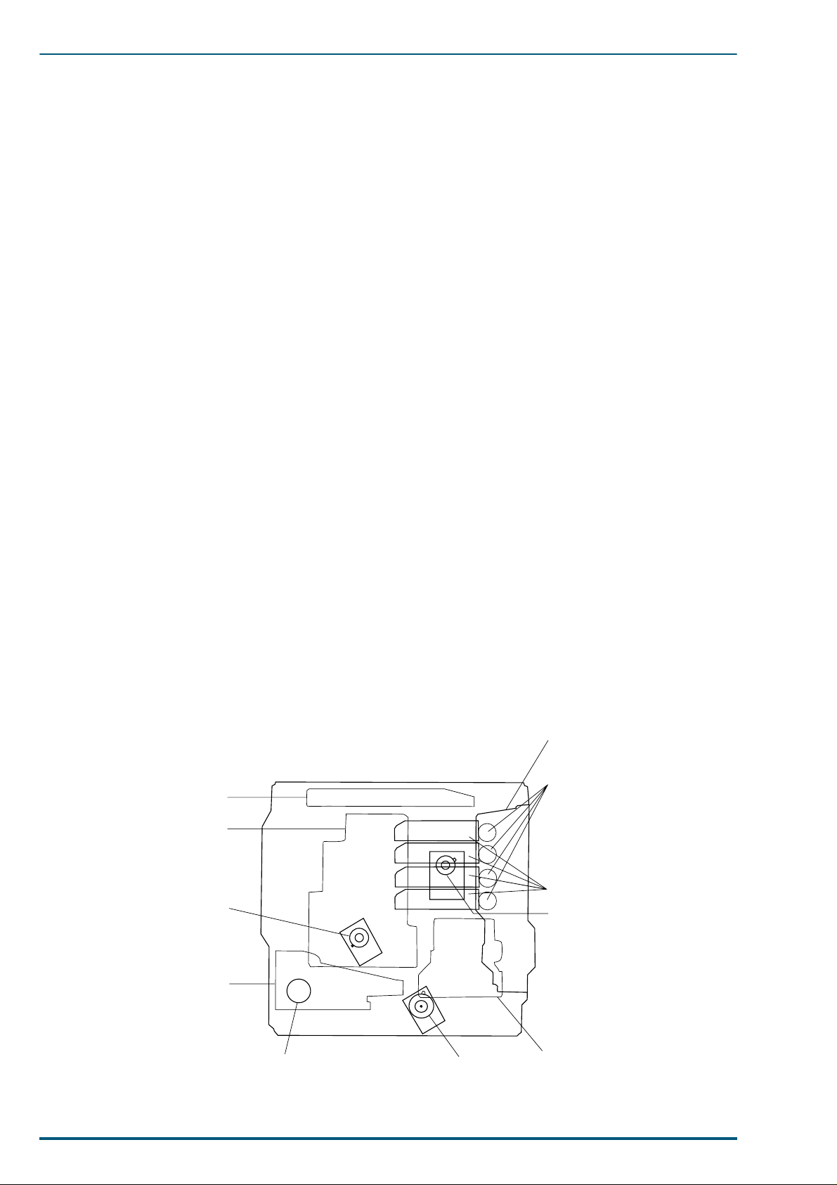
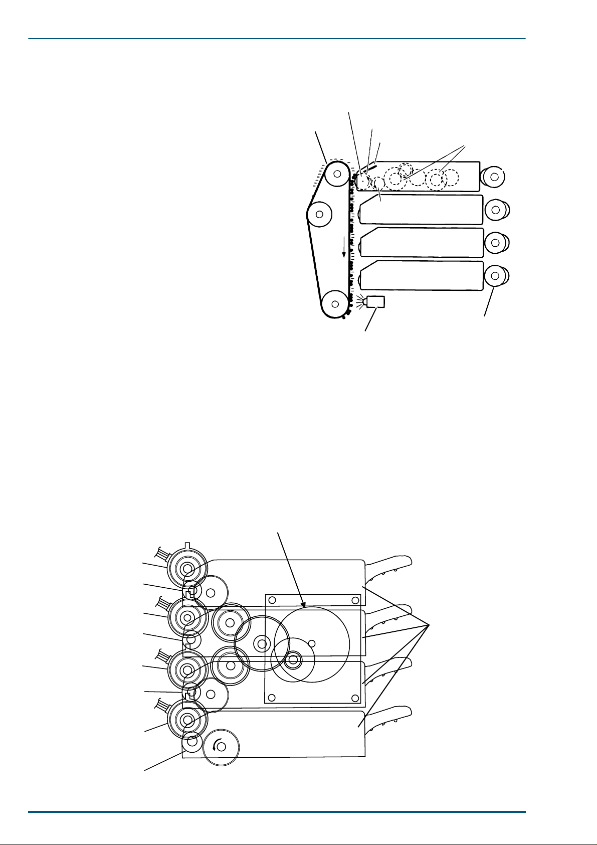
Drive Unit Layo u t
Toner Developer Selector/
Paper-eject Unit
Cam Motor
Laser Scanning Unit (LSU)
Imaging Unit
30
Main Motor
Paper Feed Unit
MP Tray Paper Feed Motor Paper Feed Motor
Toner Developer
Toner Developer
Drive Motor
Fuser Unit
Page 2
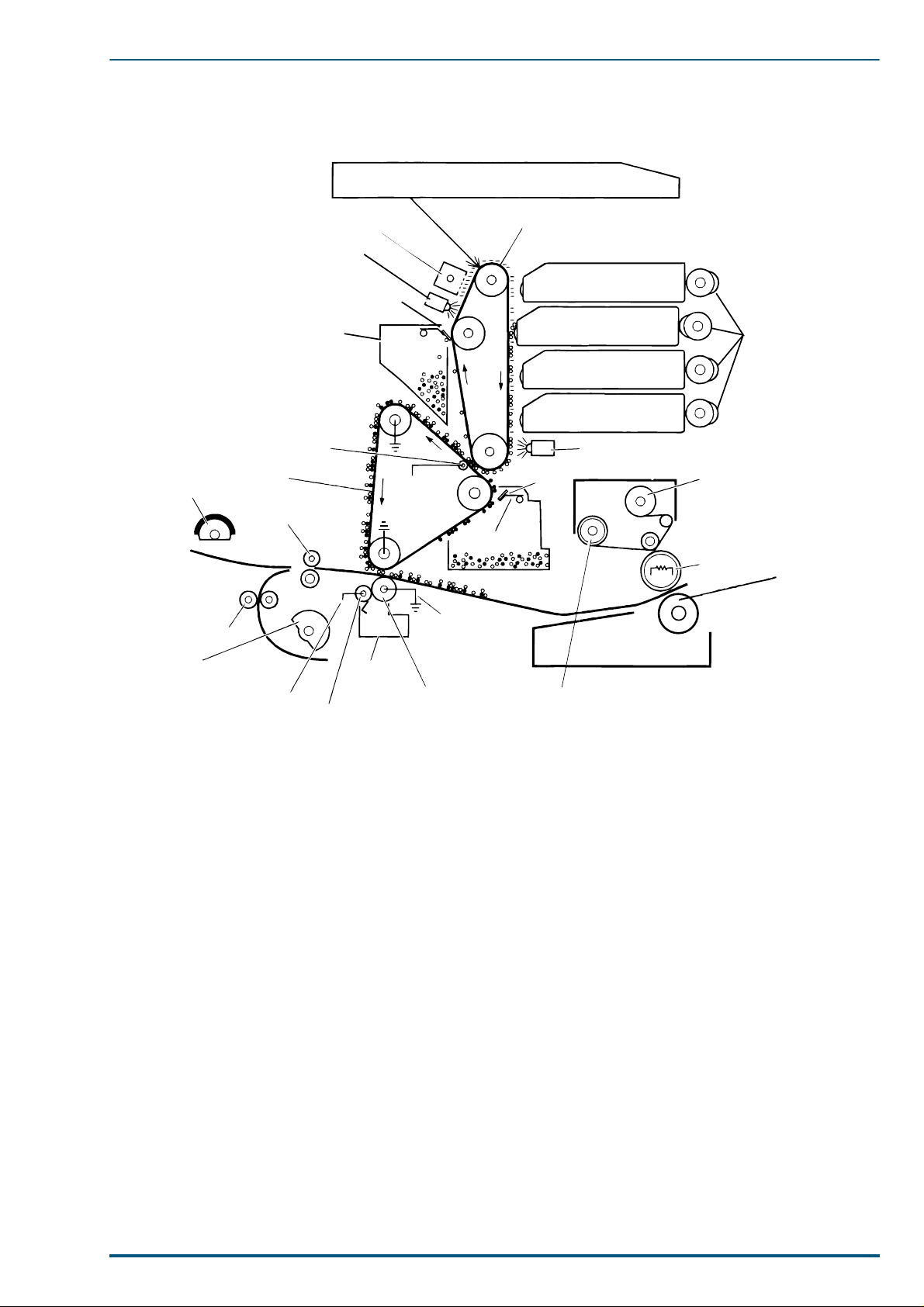
Print Process
4. Mechanical Functions
2
Laser Scanning Unit (LSU)
Multipurpose
Tray Pickup
Roller
5
Intermediate
Rollers
Pickup
Roller
Transfer Roller
(+300 V)
1
Erase Lamp
OPC Belt
Cleanning Blade
OPC Belt Cleaner
4
First Bias
Transfer
Roller
Accumulator
Belt
Registration
Rollers
Scorotron Charger
+500 ~ 700 v
6
Waste
Toner
Bin
Cleaning
Roller
(+500 to 2600,
depending on
media and
humidity)
Second Bias
Transfer
Roller
OPC Belt
Accumulator
Belt Cleanning Blade
On-Off
Supply
Roller
Toner Cartridges
Black
Cyan
Magenta
Yellow
Pre-Transfer Lamp
Fuser
3
Toner Cartridge
Selector Cam
Take-up Roller
Heated Roller
Pressure
Roller
7
Each block is explained in the following sections:
1. 4.2.1 Discharge and Charging
2. 4.2.2 Laser Exposure and Scanning
3. 4.2.3 Developing
4. 4.2.4 Toner Transfer to the Accumulator Belt
5. 4.2.5 Paper Pickup
6. 4.2.6 Toner Transfer to Paper
7. 4.2.7 Fusing and Exiting
31
Page 3
FS-5900C Service Manual
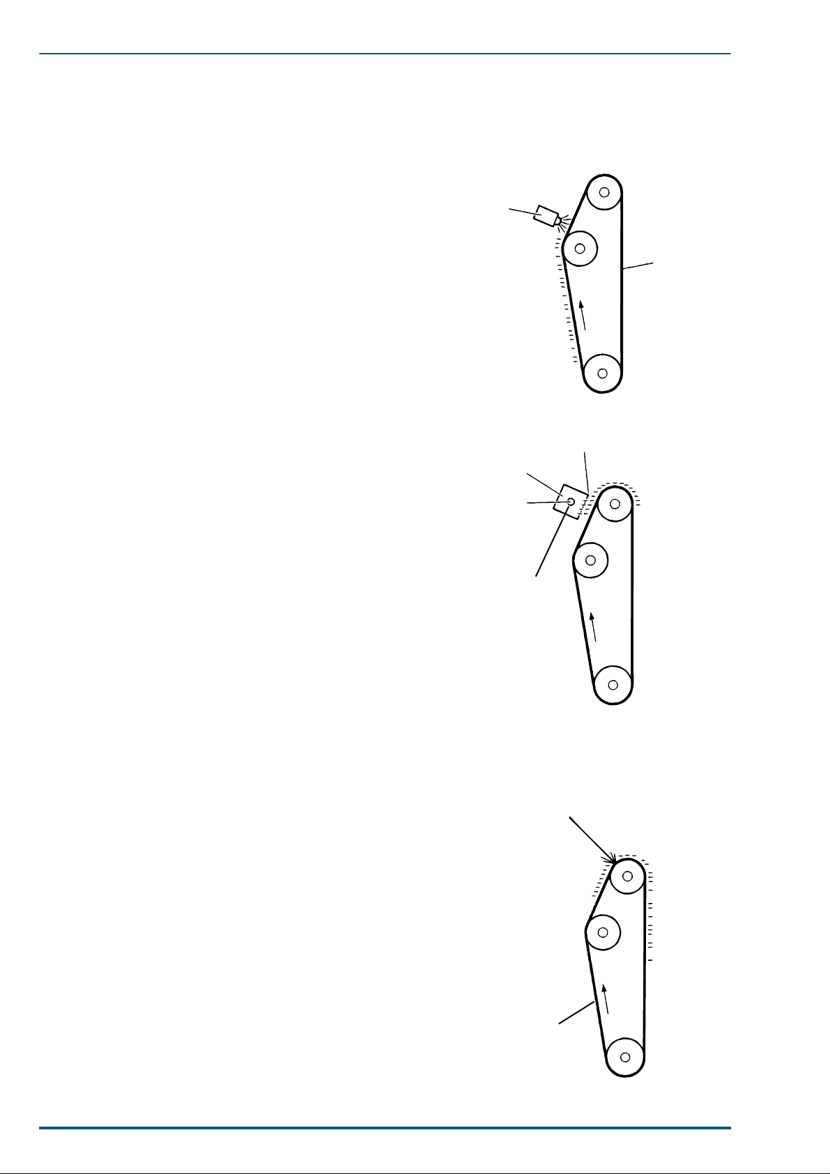
OPC Belt
Laser Beam from LSU
4.2 Print Process
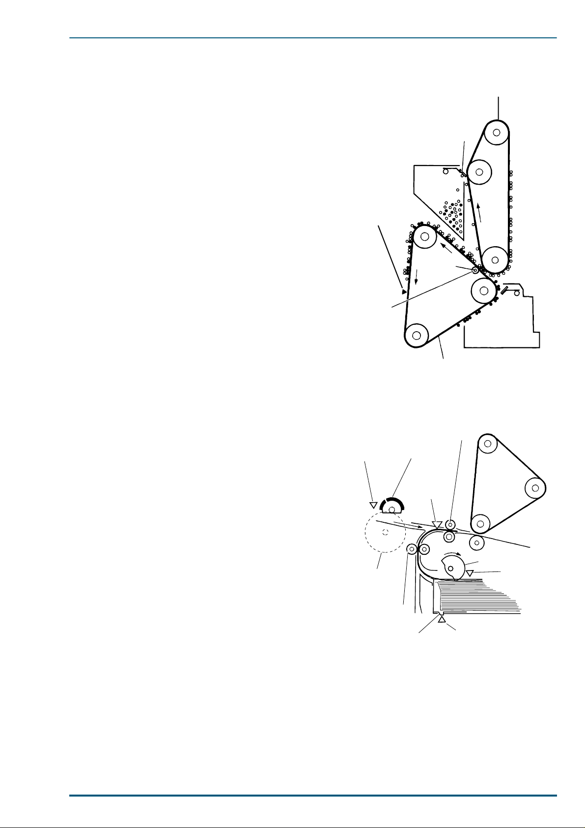
4.2.1 Discharging and Charging
Discharge
The print process begins when the OPC belt passes by
the erase lamp. The belt is rotating at 100 mm-per-second for 600 dpi printing or 53 mm-per-second for 1200
dpi printing. The light of the erase lamp, which is a horizontal row of red LEDs, removes random negative
charges from the OPC belt. Before pre-exposure, the surface of the belt varies from -500 volts to +50 volts. After
pre-exposure, the surface of the belts is 0 to -20 volts.
The pre-erase lamp is called the erase lamp since it
erases negative charges from the belt.
Charge
The electrostatic potential of the belt is not uniform following discharging. As the belt rotates, it passes a scorotron charger, which bombards the belt with negative
charges. The scorotron charger behaves somewhat like a
vacuum tube. The grid of the charger, held at a potential
of between -450 volts to -600 volts and coupled with the
varying voltage potential on any discrete point on the
belt’s surface, determines how many electrons can flow
from the corona wire onto that point of the belt’ s surface.
The corona wire is charged to -5 kilovolts with a constant
current of -400µA. The varying electron output from the
scorotron, directly based on the varying charge of the belt
surface, ensures a uniform negative potential of -440
volts or -590 volts on the belt surface, depending on the
selected dot-per-inch printing and ambient temperature.
Erase Lamp
Scorotron
Charger
Tungsten Wire
OPC Belt
Grid -450 ~ -600v
-5kv
4.2.2 Laser Exposure and Scanning
Laser Exposure
As the OPC belt rotates, the uniformly charged belt is
exposed by the modulated laser beam. The verticallymoving belt passes in front of the horizontall y scanning
laser beam, and negative charges on the belt surface are
neutralized by the beam. This forms a latent image.
Laser output power is either 0.26 mW or 0.33 mW,
depending on whether the printer is printing in 1200
dots per inch (dpi) mode or 600 dpi mode. The laser exposure, the negative potential on the belt varies from -440
volts or -590 volts (unexposed) to -10 or -20 volts (fully
exposed).
32
Page 4
4. Mechanical Functions
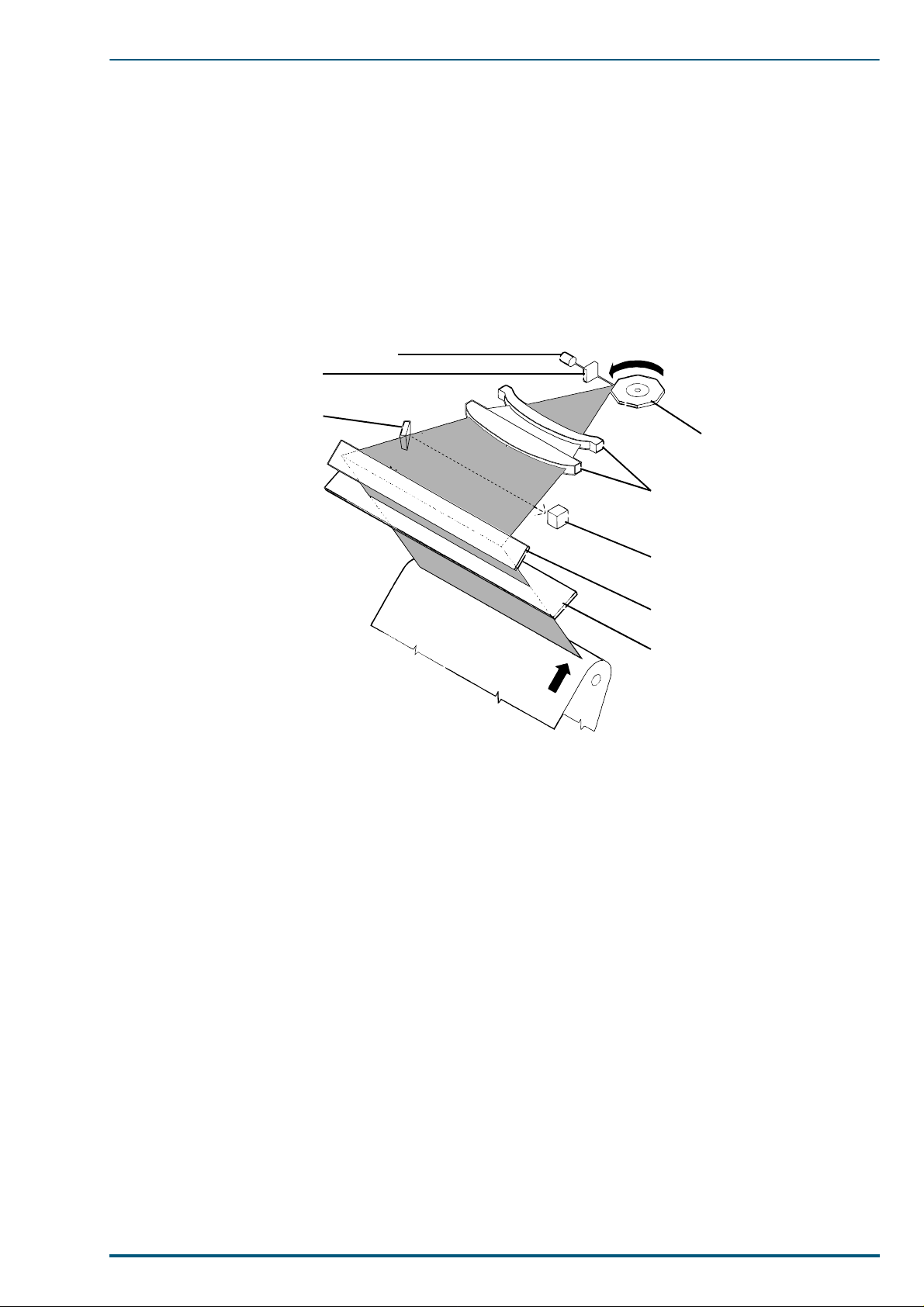
Laser Scanning
A laser diode generates the laser beam, and lenses and mirrors in the laser scanner direct the beam at the
photoconductive belt. The beam is made parallel by the collimator lens and is directed at the rotating polygonal mirror. The mirror rotates at a constant 25,197 revolutions per minute. This transforms the beam into
a horizontally scanning beam, which is directed through the f-θ primary lens, altering the beam’s angular
rotation motion into a constant horizontal motion. The toric correction lens corrects the beam for any vertical misregistration. Next, the beam reflects off of a mirror and passes through a window where it scans
across the rotating photoconductive belt. At the beginning of e ach horizontal sweep, the horizon tal sync mirror deflects the laser beam to the horizontal sync sensor. This informs the engine control board that the
laser beam is beginning its horizontal sweep and that it can begin to modulate the signal with the data to be
printed on that line of the image.
Laser Diode
Collimator Lens
Horizontal-Sync Mirror
Polygon Mirror
Fθ Lens
Horizontal-Sync Sensor
Mirror
Fθ Lens
33
Page 5
FS-5900C Service Manual
4.2.3 Developing
Developing
As the OPC belt co nti nue s t o ro ta te, i t pa sse s b y the fou r
toner developers. Each cartridge is selectively camdriven forward to bring its developer roller into direct
contact with the belt at the appropriate time.
The currently activated toner developer’s developer
roller is charged to a potential between -120 to -260 volts.
Toner is attracted to the exposed portions of the belt in
reverse proportion to the negative charge. The greatest
amount of toner is transferred to the most positive potential. The developer roller rotates at 1.8 (600 dpi printi ng)
or 2.13 (1200 dpi printing) times the speed of the OPC
belt to ensure a constant supply of toner.
OPC Belt
Developer Roller
(-120 to -260v)
Doctor Blade
Supply
Roller
Paddles
Black
Cyan
Magenta
As the belt advances, it passes the pre-transfer lamp,
Yellow
which, like the discharge lamp, removes remaining negative charges from the unexposed portions of the belt.
Inside each toner developer is a toner supply roller that
rotates in the opposite direction from the developer
roller. This supplies a layer of toner onto the developer
Pre-transfer
Lamp
Toner Cartridges
Cartridge Selector Cam
roller. The doctor blade smooths and evenly distributes
the toner on the developer roller. Gear-driven paddles
churn the toner and keep it fluidized and moving
towards the developer roller.
Toner Developer Drive
Drive is supplied from the toner developer drive motor. At the proper time, the clutch corresponding with
the currently selected toner developer is activated by a signal from the CPU, transmitting drive to the
clutch gear via idle gears. Drive is then transmitted to the developer rollers.
The toner level sensing receiver board detects whether each of the four toner developers contains sufficient
toner. This board is paired with the toner level sensing transmitter board and functions as the photo sensors.
Toner Developer Drive Motor
Clutch Gear
Developer Roller
Black
34
Clutch Gear
Developer Roller
Clutch Gear
Developer Roller
Clutch Gear
Developer Ro ller
Cyan
Magenta
Yellow
Toner Developers
Page 6
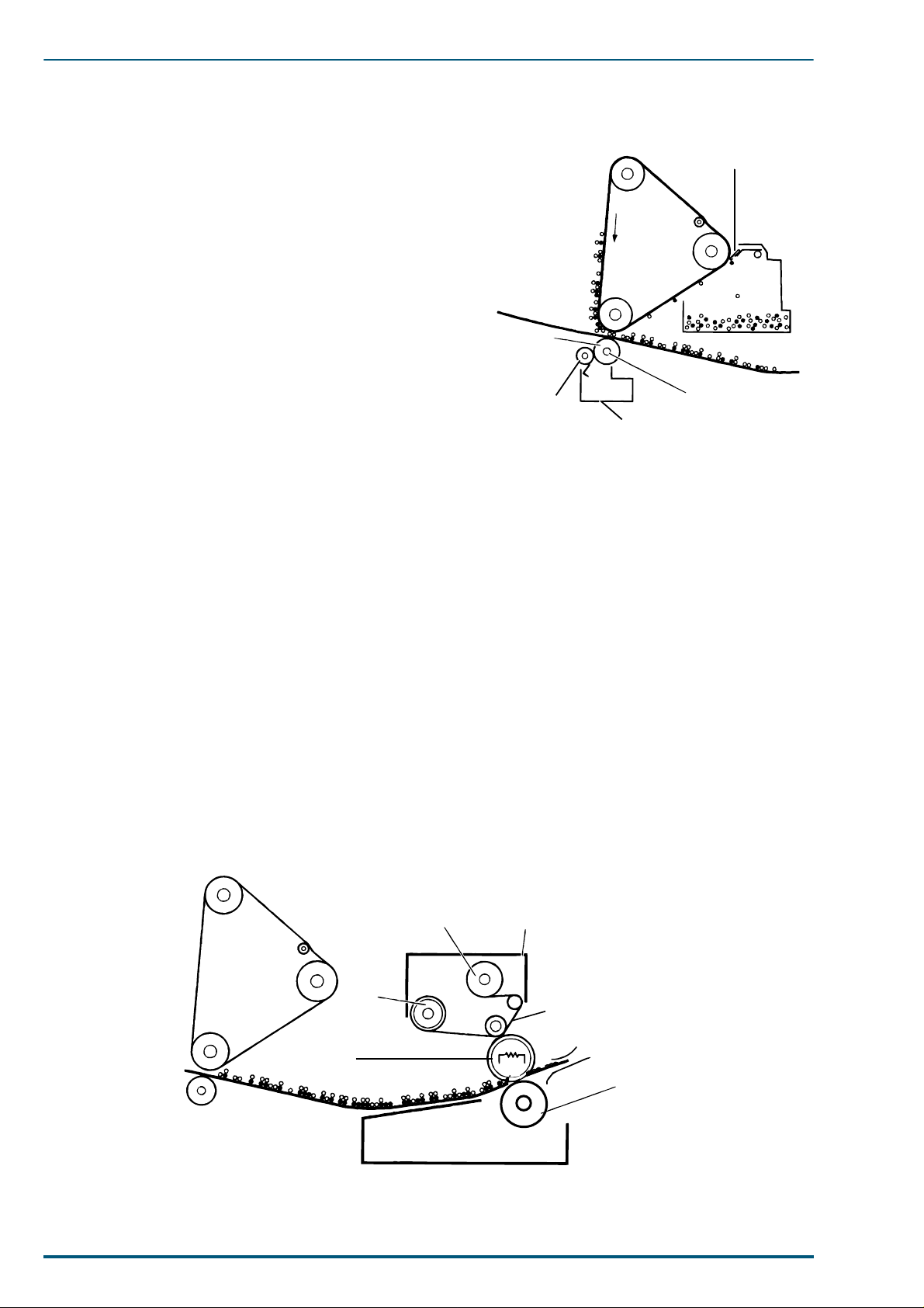
4.2.4 Toner Transfer to the Accumulator Belt
OPC BeltCleaning Blade
OPC Belt
+500 to 700v
Accumulator
Belt Home
Sensor
First Bias
Transfer
Roller
Accumulator
Belt
Multipurpose
Tray Pickup
Roller
Registration
Roller
Registration
Sensor
Intermediate
Rollers
Pickup Rollers
MP Tray Paper
Out Sensor
MP Tray Paper
Feed Motor
Paper Empty
Sensor
Paper Cassette Sensor
Terminal for detecting
paper cassette
As the OPC belt rotates, it comes in contact with the
accumulator belt, which is rotating at the same speed.
Located under the accumulator belt at the contact point
with the OPC belt, the first bias transfer roller carries a
charge that varies between +500 and +700 volts (based
on the sensed temperature, humidity and print speed).
This strong potential attracts and holds the toner from
the OPC belt to the accumulator belt. The accumulator
belt makes four complete rotations, one for each of the
four toner layers. The accumulator belt home-position
sensor sync signal, generated from a timing mark on the
accumulator belt, informs the engine control board when
to begin expo sin g t he O P C be lt wi th information to b ui ld
the next tone r lay er. At tha t time, the a ccumul ator belt i s
rotated to the proper position to transfer the toner layer
in proper registration with the previous layer(s).
Any toner remaining on the OPC belt after the transfer
to the accumulator belt is scraped off by the OPC belt
cleaning blade, which is always in contact with the belt.
This leaves the OPC bel t cl ean f or t he next la yer of to ner
to be transferred from the toner developers.
4. Mechanical Functions
4.2.5 Paper Pickup
The cam-shaped pickup rollers are driven by the paperfeed motor and force a sheet of pape r between the intermediate rollers. The pickup roller completes only one
rotation to pick a sh eet of media . This will push the s heet
of paper to the intermediate rollers but does not pick a
second sheet. Alternately, depending on the user’s selection, media may be picked from the multi-purpose tray.
The multi-purpose tray pickup roller is driven by the
M.P.T paper feed motor and feeds a shee t of media or an
envelope into the registration rollers.
The intermediate rollers advance the sheet of paper to
the registration rollers. The paper is driven lightly
against the stationary registration rollers to create a
slight buckle in the paper , aligning the sheet of paper. At
this point, the paper remains stationary (since the registration roller’s clutch is not yet energized) until the
image is ready to be printed on the paper. T h e registration sensor detects whether the sheet of paper arrived at
the aligning rollers after being properly picked and
traveling through the intermediate rollers.
The paper feed unit has the MP tray paper out sensor,
paper empty sensor and paper cassette sensor. The MP
tray paper out sensor detects whet her the paper i s set on
the manual feed tray. The paper empty sensor detects
whether the paper is set i n the paper cass ette. The paper
cassette sensor detects paper cassette presence and
paper size.
35
Page 7
FS-5900C Service Manual
4.2.6 Toner Tr ansfer to Paper
Once all four layers of toner reside up on the accumulator belt, the registration roller clutch is energized to
advance a sheet of paper (which has alre ady been picked)
to the second bias tra ns fer rolle r. The toner image on the
rotating accumulator and the paper that is being fed into
the image unit are synchronized for proper alignment.
The leading edge of the toner image on the accumulator
belt is aligned 5 mm from the leading edge of the paper.
A strong positive voltage in the second bias transfer
roller attracts the toner from the accumulator belt to the
paper. The transfer roller voltage varies from +500 to
+2600 volts based on the ambient temperature, humidity ,
print speed and media being prin ted upon. T he p aper (o r
transparency film) advances at the same speed as the
accumulator belt.
As the toner is being transferred to the paper, the accumulator belt cleaning blade is activated. This blade
scrapes any remaining traces of toner from the accumulator belt prior to the next image transfer. Residual toner
is removed from the second bias transfer roller by a
cleaning roller that is held at a potential that is +300v
higher than the second bias transfer roller. A blade
scrapes the toner off the cleaning roller into the toner
waste bin.
Second Bias
Transfer Roller
Cleaning
Roller (+300 V
higher than
STR)
Accumulator Belt
Cleaning Blade
+500 to 2600 V
Waste
Toner
Bin
4.2.7 Fusing and Exiting
Fusing
After the toner image has been applied to the paper, it passes through the fuser. A heated roller melts the
toner and pressure drives it into the paper. The melted toner bonds to the paper. An oil supply keeps the
heated roller lubricated so that the melted toner does not adhere to the roller. After fusing, the paper
advances to the output tray. When the printer is idle, the heated roller is held at a temperature of 150 °C.
The heated roller is set to 156 °C for 600 dpi printing and 137 °C for 1200 dpi printing. For transparency
film and other media the fuser is set to 160 °C and ran at half speed. The paper ejection sensor detects the
sheet of paper as it leaves the fuser.
Take-Up
Roller
Supply
Roller
Heated
Roller
Fuser Roll
Oil (soaked)
Pressure
Roller
36
Fuser
Page 8

4. Mechanical Functions
Reverser
The reverser allows
the prints to exit to
the exit tray printed
side down
Output Tray
Paper Full
Sensor
Paper Exit
Sensor
Output
Tray
Paper Ejection
Sensor
Fuser
Switchback
Support Roller
Switchback
Roller
Switchback
Support
Roller
Paper ejection
roller #1
Switchback
Gate
Switchback
Roller Shaft
Switchback
Solenoid
Paper Path
Eject
If face up eject is selected, the paper goes directly to the output tray unde r the switchback gate, printed side
up.
Paper Ejection
Sensor
Output Tray
Paper Full Sensor
Paper Path
Paper Exit
Sensor
Output
Tray
Fuser
Or, if face down eject is selected, the switchback
solenoid on the toner developer selector/paper eject
unit is activated to hold th e s wi tchb a ck ga te i n t he
down position, allowing the paper to be fed to the
reverser, which drives the sheet up a narrow channel. At this time, the switchback shaft linked with
the switchback gate moves to position A. At the
proper time, the switchback solenoid is turned off,
which returns the switchback gate to the up position. Also, the switchback shaft moves to position
B. These movements reverse direction and routes
the sheet of paper to the output tray printed side
down. This is appropriate for a collated series of
prints that need to remain in first-to-last order.
The paper exit sensor detects the sheet of paper as
it enters the exit rollers.
Switchback Gate
Position A
Switchback
Gate
Switchback
Shaft
Paper
Position B
Paper Path
Paper ejection roller #2
37
 Loading...