

Page 1
FS-5900C Service Manual
9. Troubleshooting
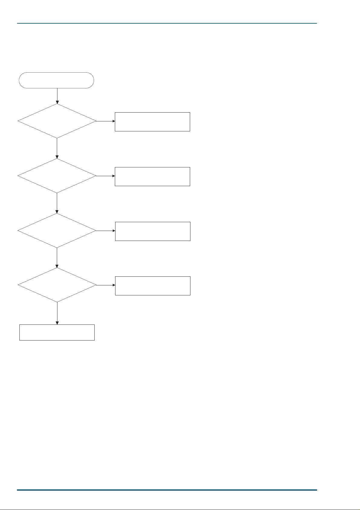
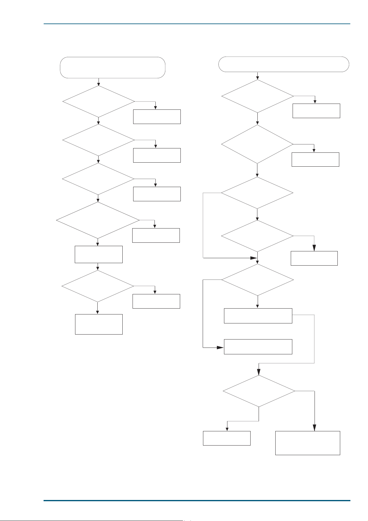
9.1 Initial Troubleshooting Flowchart
Start
Is a message
displayed?
Y
Is an error code
displayed?
N
Is print quality
normal?
Y
Does paper feed
normally?
N
Y
N
N
No Message Section
(Section 9.6)
Error Message Section
(Section 9.2)
Print Quality Section
(Section 9.4)
Paper Jam Section
(Section 9.3)
Y
End
102
Page 2

9. Troubleshooting
9.2 Error Messages
The printer indicates error conditions using the ON and blinking states of the ATTENTION indicator. When
the ATTENTION indicator is lit in red, it shows call service error status. When it is blinking, it shows user
correctable error status.
9.2.1 Error Messag es
Error Message Possible Cause Corrective Action
Add paper
paper source
<
Battery error
MEMORY CARD
Call service
person##:#######
Cassette 1
not loaded
Cassette 2
not loaded
Cassette 3
not loaded
Format error
<Media>
Front/Right
cover Open
HARDDISK error##
Press CONTINUE
>
The paper source is out of paper. Add paper to the paper cassette (Cassette 1),
The memory card’s battery is run
out or not installed.
A failure requiring the attention of
service personnel has occurred.
The printer’s media cassette is not
loaded in the printer, or not closed
fully in position.
The paper feeder’s top media cassette is not loaded in the paper
feeder, or not closed fully in posision.
The paper feeder’s bottom media
cassette is not loaded in the paper
feeder, or not closed fully in posision.
The hard disk or memory card is
not formatted.
The front or right sid e cover is
open.
The printer has encountered an
error during access to th e option
harddisk.
option paper feeder’s cassettes (Cassette 2 and
3), or multi-purpose tray (MP Tray).
Insert a new battery in the memory card. (See
the memory card manufacturer’s instruction.)
Note the corresponding error code (## followed by
the colon) and the total printed pages1 (#######
preceded by the colon). Turn printer power off
and call for service. For details, see section 9.2.2
Call Service person Codes. (The total printed
pages is not shown when the error code is F 0
[Communication error].)
Insert the media cassette, or close it securely.
(Cassette 1 is shown as Cassette w hen no option
paper feeder is installed.)
Insert the top media cassette, or close it securely.
(This message is shown only when the printer is
installed with an option paper feeder.)
Insert the bottom media cassette, or close it
securely. (This message is shown only when the
printer is installed with an option paper feeder.)
Format the media. See the appropriate section in
the User’s Manual for details.
Check both covers and close them tightly.
Note the error code (##) preceded by the HARDDISK error message. Then, press
clear the error situation. Refer to the appropriate
section in the User’s Manual for details.
CONTINUE
to
I/F occupied
Imaging unit
not locked
Insert the same
MEMORY CARD
KPDL Error ##
Press CONTINUE
Left cover Open
The front control panel operation
you attempted is not possible
because that interface is receiving
data.
The imaging unit is not locked
properly because its lever is not
lifted.
A different memory card was
inserted following the
&$5'#HUU2,QVHUW#DJDLQ
sage.
The printer encountered an error
during processing data in KPDL
mode.
The left side cover is open. Close it tightly.
0(025<#
mes-
Wait until the data transfer is completed on that
interface.
Lift the imaging unit lever fully up.
Reinsert the same memory card as was removed
previously into the printer’s memory card slot.
Note the error code of ## and press
clear the error situation. See the app r opriate section in the User’s Manual for details.
CONTINUE
to
103
Page 3

FS-5900C Service Manual
Error Message Possible Cause Corrective Action
Load paper
<paper size>
MEMORYCARD err##
Press CONTINUE
MEMORY CARD err
Insert again
Memory overflow
Press CONTINUE
Missing FK-81
Fuser KIT
Missing IU-81
Imaging unit
Missing OS-81
Oil supply roll
Missing Toner
TD-81C (Cyan)
The paper size does not match. Put the media cassette loaded with the paper of
the correct size as specified by the a pplication
software into the printer. To resume printing
using the current media cassette, press CONTINUE.
(You must press CONTINUE every time one sheet
has been printed, be ca use the sam e me ssa ge w il l
again be displayed from the second sheet
onward.) To abandon printing, press CANCEL.
The printer has encountered an
error during access to t he memory
card.
The memory card was removed
during the memory card operatin.
The print data from the computer
is larger than the printer can fit in
its memory.
The fuser kit is not installed in the
printer.
The imaging unit is n ot i nstalle d i n
the printer.
The oil supply rolle r is not installe d
in the printer.
The cyan toner developer is not
installed in the print e r.
Look at the error code of ## preceded b y MEM ORYCARD err. Then, press CONTINUE to clear the
error situation. Refer to the appropriate section
in the User’s Manual.
Re-insert the same memory card into the
printer’s memory card sl ot. The printer will continue with the memory card operation.
Press CONTINUE to print the data. Install additional memory or use a lower resolution print
quality.
Install the fuser kit.
Install the imaging unit .
Install the oil supply rol le r.
Install the cyan toner developer.
Missing Toner
TD-81K (Black)
Missing Toner
TD-81M (Magenta)
Missing Toner
TD-81Y (Yellow)
Missing
Charger unit
Missing paper
feeder unit
Option feeder
Left cover Open
Opt. ROM error
Press CONTINUE
Option interface
Error ##
Output tray
paper full
PJL OPMSG/STMSG The printer encountered an error
The black toner developer is not
installed in the print e r.
The magenta toner developer is not
installed in the print e r.
The yellow toner developer is not
installed in the print e r.
The charger unit is not installed in
the printer.
The paper feeder unit is not
installed in the print e r.
The paper feeder’s left side cover is
open.
The printer has encountered an
error while accessing data in the
option EPROM (on the printer
main board).
The printer has detected an error
on the option inte rface.
The output tray has become full. Remove paper from the output tray.
during processing PJL commands.
Install the black toner developer.
Install the magenta toner developer .
Install the yellow toner developer.
Install the charger unit in the imaging unit.
Install the paper feeder unit.
Close it tightly.
Press CONTINUE to print the data processed so far.
Replace the option EPROM.
Note the error code of ## and consult your Kyocera dealer.
Press CONTINUE to print the page processed so far.
Paper jam
Location
<
Print overrun
Press CONTINUE
Replace FK-81
Fuser KIT
>
104
Paper has become jammed. Remove jammed paper according to the appropri-
The printer has received print data
that is too complex to finish processing in time with the operation
of the printer mechanism.
The fuser is worn out. Replace the fuser ki t now.
ate section in the User’s Manual.
Press CONTINUE to print the data. Install addi-
tional memory or use a lower resolution print
quality.
Page 4

9. Troubleshooting
Error Message Possible Cause Corrective Action
Replace IU-81
Imaging unit
Replace OS-81
Oil supply roll
Replace Toner
TD-81C (Cyan)
Replace Toner
TD-81K (Black)
Replace Toner
TD-81M (Magenta)
Replace Toner
TD-81Y (Yellow)
Reset Transf.Roll
Press ENTER
Set paper
Press CONTINUE
Toner low
TD-81C (Cyan)
The imaging unit is worn out. Replace the imaging unit now.
The oil supply roller is worn out. Replace the oil supply roller now.
The cyan toner developer is empty. Replace the cyan toner developer now.
The black toner developer is empty. Replace the black toner developer now.
The magenta toner developer i s
empty.
The yellow toner developer is
empty .
The printer is waiting for your
input of confirming that you have
replaced the trans fer roller and
resetting its counter (User’s Manual ☞ P. 105).
The multi-purpose tray is empty. Add a sheet of paper to the multi-purpose tray,
The cyan toner developer is almost
empty.
Replace the magenta toner developer now.
Replace the yellow toner developer now.
Press ENTER and the printer resets the transfer
unit counter to 0000000.
and press CONTINUE key. (This message
appears when the multi-purpose tray is in manual mode.
Replace the cyan toner developer as soon as possible.
Toner low
TD-81K (Black)
Toner low
TD-81M (Magenta)
Toner low
TD-81Y (Yellow)
Warning FK-81
Fuser KIT
Warning IU-81
Imaging unit
Warning TR-81
Transfer roller
Warning battery
MEMORY CARD
Warning
Low memory
The black toner developer is almost
empty .
The magenta toner developer i s
almost empty.
The yellow toner developer is
almost empty.
The fuser kit is wearing out. Replace the fuser kit as soon as possible.
The imaging unit is wearing out. Replace the imaging unit as soon as possible.
The transfer roller is wearing out. Replace the transfer roller as soon as possible.
The memory card’s battery is running out.
The printer’s internal memory is
insufficient to complete the printing.
9.2.2 Call Service person Codes
LCD
Display
Printer Status Possible Cause Recovery
Replace the black toner developer as soon as possible.
Replace the magenta toner developer as soon as
possible.
Replace the yellow toner developer as soon as
possible.
Change the memory card battery as soon as possible. (See the memory card manufacturere’s
instruction.)
Press CONTINUE key to print the page processed so
far. Remove any unnecessary fonts or macros in
the printer or install additional memory.
A2 Fuser temperature is over 210 °C. High temperature error See section 9.5.10
A2 Fuser temperature does not reach 100 °C within
200sec, 165 °C within 500 sec. During warming
up, or it is less t han 120 °C du ring stan dby, and it
does not return to set temperature within 100sec
after a low temperature error occurred during
printing.
Temperature rising error See section 9.5.10
105
Page 5

FS-5900C Service Manual
LCD
Display
A5 1. Main charger Arc discharge of co ntact has
occurred.
2. DEV, FTR, STR bias short circuit of contact
voltage has occurred.
A6 Fuser/Toner Developer fan is not rotating at nor-
mal speed.
A7 Power supply fan is not rotating at normal speed. Power supply fan error See section 9.5.12
A8 Ozone fan is not rotating at normal speed. Ozone fan error See section 9. 5.13
A9 Multi-Purpose Pickup Roller movement error
occurred
AA T oner Developer Drive motor (sleeve motor) is not
phase-locked and is not rotating at normal speed.
AB Paper feed motor is not phase-locked and is not
rotating at normal speed.
AC OPC home and IT home are not synchronous. OPC asynchronous with inter-
AD OPC home is not detected within 4.5 sec. during
rotation of main motor.
AE IT home is not detected within 0.32 sec. during
rotation of main motor.
AF The cleaning blade did not reached to non-clean-
ing position or cleaning position within 0.7 sec.
B7 The media transfer roller did not reach to trans-
fer position or home position within 0.9 sec.
B8 The dev. unit did not reach contact position or
home position within 1 sec.
B9 The dev. unit did not reach contact position or
home position within 1 sec.
BA The dev. unit did not reach contact position or
home position within 1 sec.
BB The dev. unit did not reach contact position or
home position within 1 sec.
BC Engine SRAM check error Engine SRAM check error See section 9.5.19
Printer Status Possible Cause Recovery
Charger error See section 9.5.4
Fuser/T oner Developer fan error See section 9.5.2
Multi-Purpose Pickup Roller
movement error
Toner Developer Drive motor
(sleeve motor) unlocked
Paper feed motor unlocked See section 9.5.15
mediate transfer unit
Position error of the OPC unit See section 9.5.6
Position error of the intermediate transfer unit
Cleaning blade movement erro r See section 9.5.8
Media transfer roller movement error
Cyan developing unit movement
error
Magenta developing unit movement error
Yellow developing unit movement error
Black developing unit movement error
See section 9.5.17
See section 9.5.14
See section 9 .5 .5
See section 9 .5 .7
See section 9 .5 .9
See section 9 .5 .1
See section 9 .5 .1
See section 9 .5 .1
See section 9 .5 .1
BD Engine EEPROM check error. Printing is contin-
ued.
BE EEPROM (Imaging unit) check error EEPROM (Imaging unit) Error See section 9.5.22
BF EEPROM (Fuser unit) check error EEPROM (Fuser unit) Error See section 9.5.23
DE Imaging unit type mismatch Imaging Unit being used is not
DF Fuser unit type mismatch Fuser Unit being used is not
E0 Parity error occurs or no response comes back
from engine.
E1 Main motor is not phase-locked and is not rotat-
ing at normal speed.
Engine EEPROM check error See section 9.5.20
Replace Im aging
intended for use with the
printer.
intended for use with the
printer.
Engine communication Error See section 9.5.21
Main motor unlocked See section 9.5.16
Unit with the one
recommende by
Kyocera for the
printer.
Replace Fuser
Unit with the one
recommended by
Kyocera for the
printer.
106
Page 6

9. Troubleshooting
LCD
Display
E2,E3 Laser scanner motor is not phase-locked and is
not rotating at normal speed.
L-sync signal is not detected after APC (Auto
Power Control).
Irregular L-sync signal is detected. L-Sync short See section 9.5.3
E4 Fuser thermistor is disconnected. Thermistor open error See section 9.5.11
E6 Engine progra m RO M checksum error Engine Program RO M check-
F0 Controller board system lock error System does not lock because of
F1 Controller checksum error Checksum failed on Controller
F2 RAM Read/write error Checksum has failed on Con-
F3 System error General controller failure. See section 9.5.27
F7 Option font ROM checksum error Checksum has failed on option
Memory
Overflow
Memory overflow has occurred. Print data is larger than the
Printer Status Possible Cause Recovery
Laser scanner motor unlocked See section 9.5.3
L-Sync over See section 9.5.3
sum error
failure on communication with
the printer panel.
ROM.
troller RAM.
font ROM.
capacity of the memory
installed.
See section 9.5.18
See section 9.5.24
Replace Main
Controller Board.
See section 9.5.26
Replace the option
font ROM.
See section 9.5.25
107
Page 7
FS-5900C Service Manual
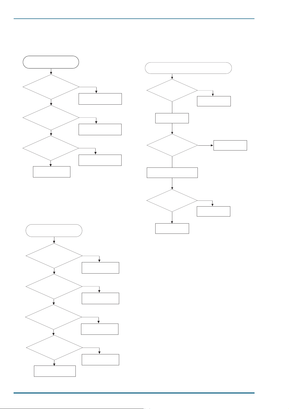
9.3 Jam
9.3.1 Print Media Problem
Printer Media Problem
Is the print media
being used within
specification?
Y
*
Is print media in
good condition?
Y
Is the correct tray
being used?
Y
Check again.
*
Inspect the print media for bent,
torn or folded corners etc.
N
Use print media that is
within specification.
N
Use undamaged print
media.
N
Use the correct tray.
9.3.3 Printer cannot distin guish
between paper and t ransparen cy.
Printer cannot distinguish between
paper and transparency.
Is the appropriate
media tray being
used?
Y
Replace the sensor
board.
Is printer work
OK?
N
If necessary, reinstall the
original board.
N
Use the appropriate
media tray.
Y
End
9.3.2 Print Media skews.
Printer Media skews.
Does the pickup
roller pickup the
media evenly?
Y
Are the MPT paper
guides snugly
adjusted against the
media?
Y
Are the corners of
the media under the
tray tabs?
Y
N
Check and clean
the pickup roller.
N
Adjust or replace
the paper guides.
N
Set the media
under the tabs.
Is the cable
connected to the
sensor board
normal?
Y
Replace the engine
control board.
N
Replace the cable
(CN11).
108
Is the paper guide on
the left door normal?
Y
Check for obstacle
blocking the paper path.
@
N
Remove burs or
foreign obstructions.
Page 8
9. Troubleshooting
N
N
N
Y
Clean the pickup
rollers.
Paper jams midway in the paper feeder.
(Front panel displays Paper Jam/B.)
Are the pickup
rollers clean?
Y
* Is the paper guide
on the left door
normal?
* Check for burrs or foreign obstructions.
Y
Clean the paper
feed rollers.
Are the paper feed
rollers clean?
Y
Replace the clutch
assembly.
Does the pickup
roller clutch work
properly?
Check again.
N
Remove burrs or
foreign obstructions.
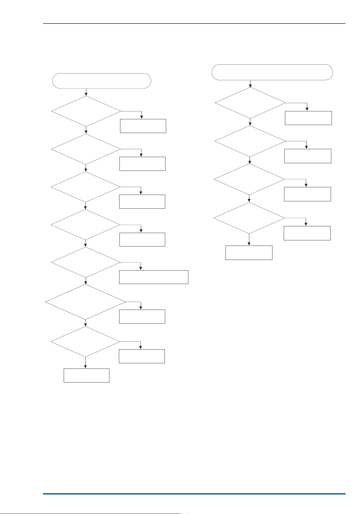
9.3.4 Paper jams at the media cassette.
Paper jams at the media tray.
(Front panel displays Paper Jam/A.)
Are the pickup
rollers clean?
Y
Is the paper feed
motor normal?
Y
Are the gears
normal?
Y
N
Clean the pickup
rollers.
N
Replace the paper
feed motor.
N
Replace the gear.
9.3.5 Paper jams mi dway in the p aper
feeder .
* Is the pickup roller
correctly installed?
Y
Does the pickup
roller solenoid
work properly?
Y
Are the cables and
connectors between
paper feed unit board
and engine control board
normal?
Y
Are the other
areas of the paper
feeder normal?
Y
Check again.
*
Flat side of the cam-shaped pickup rollers
face down prior to pick a sheet of paper.
N
Install the pickup
roller properly.
N
Check or replace the solenoid
and paper feed unit board.
N
Replace the
defective parts.
N
Replace the
defective parts.
109
Page 9
FS-5900C Service Manual
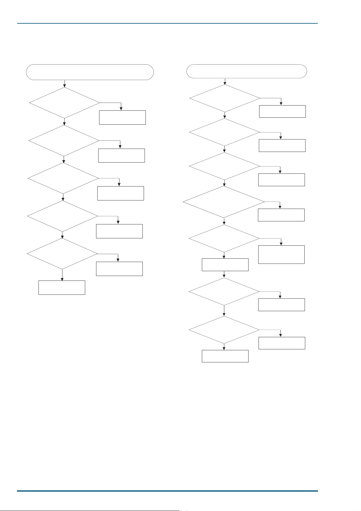
9.3.6 Paper jams at the second bias
transfer roller.
Paper jams at the second bias transfer roller.
(Front panel displays Paper Jam/B.)
Is the transfer
roller correctly
installed?
Y
Does the
registration sensor arm
properly interrupt the
sensor?
Y
Are the registration
rollers clean?
Y
Does the
registration clutch
work properly?
Y
Are the registration
springs installed
properly?
Y
N
Install the transfer
roller correctly.
N
Correct movement
of the sensor arm.
N
Clean the
registration rollers.
N
Replace the
registration clutch.
N
Install the springs
properly.
9.3.7 Fuser Jams
Fuser Jams.
(Front panel displays Paper Jam/C.)
Are the Fuser
gears normal?
Y
Can the fuser
knob be turned
normally?
Y
Does the fuser exit
sensor arm operate
properly?
Y
Are the cables and
connectors for fuser
exitboard, exit sensor board
and engine control board
normal?
Y
Does the paper
ejection roller
rotate?
Y
Replace the engine
control board.
N
Replace the fuser
unit.
N
Replace the fuser.
N
Correct movement
of the sensor arm.
N
Replace the cable
and connector.
N
Check the toner
cartridge selector/
paper-eject unit.
Check again.
Does the trouble
still occur?
Y
Fuser cleaning pad
Is
clean?
Y
Replace the fuser
unit.
N
N
Clean fuser
cleaning pad
End
110
Page 10
9. Troubleshooting
Is the multi-purpose feed
motor fixed to metal plate
properly?
N
N
Y
Correct movement
of the arm.
Multi-purpose Tray Jams.
(Front panel displays Paper Jam/A.)
Does the
multi-purpose tray
sensor arm actuate its
sensor properly?
Y
Replace the cable.
Is the
cable from the paper
feeder to the engine control
board (CN604)
normal?
Y
N
Does the multipurpose pickup
roller shaft rotate?
*2 Replace the paper feed
unit board or engine
control board.
Y
N
Is the retard pad
able to move up
and down?
Repair the retard
pad.
N
Y
Replace the multi-purpose
feed motor.
Does the multipurpose pickup
roller shaft rotate?
N
Y
End
Correct the multi-purpose
feed motor.
9.3.8 Eject Jams 9.3.9 Multi-purpose Tray Jams
Eject Jams.
(Front panel displays Paper Jam/D
or Paper Jam/E.)
Are all the ejection
rollers clean?
Y
*1 Are the switch
back levers
normal?
Y
Does the
paper ejection sensor
arm actuate its sensor
Are the cable and connector
properly?
Y
to the engine control
board (CN611) normal?
Y
*2 Replace the
engine control
board.
N
Clean the ejection
rollers.
N
Correct movement
of the levers.
N
Correct movement
of the sensor arm.
N
Replace the cable.
Does the trouble still
occur?
Y
Check the toner
cartridge selector/
paper eject unit.
Ensure that the levers are not bent and do not
1
*
interfere with paper movement.
When replacing the engine control board,
2
*
remove EEP ROM (IC6) from the original
engine control board and install it on the new
engine control board.
N
End
111
Page 11
FS-5900C Service Manual
9.4 Print Quality
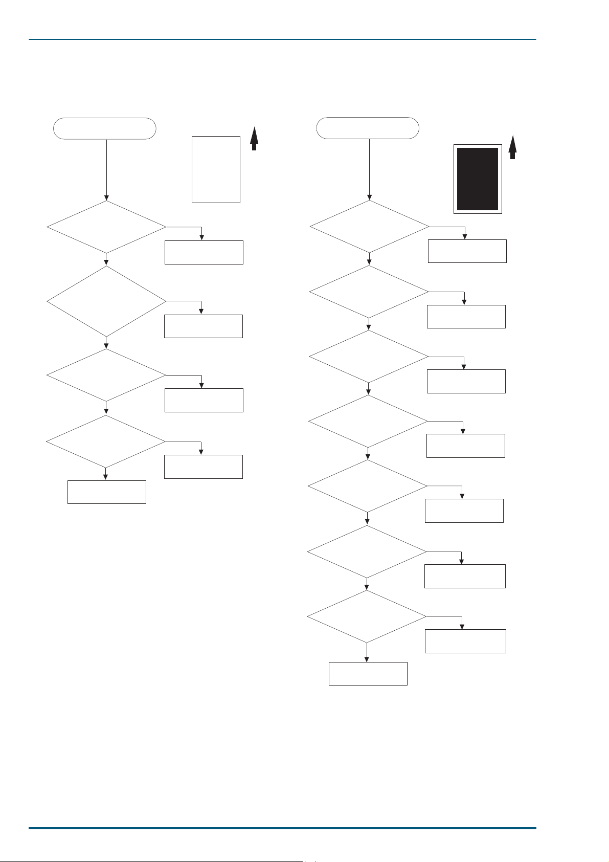
9.4.1 Blank Print 9.4.2 A ll-black Print
Blank Print
Is the laser unit
normal?
Y
Is the toner
cartridge selector pushing
the toner cartridge into
contact with the
belt?
Y
Is the toner
cartridge drive unit
normal?
Is the imaging unit
normal?
Y
*1
Replace the engine
*1
When replacing the Engine Control Board, remove
EEPROM (IC6) from the original Engine Control Board
and install it on the new Engine Control Board.
*2
When replacing the Printer Main Control Board,
remove IC9 from the original Printer Main Control
Board and install it on the new Printer Main Control
Board.
control board.
N
Replace the laser
unit.
N
Check the toner
cartridge selector.
N
Repair the toner
cartridge drive unit.
N
Replace the
imaging unit.
Paper Travel
All-black Print
Is the imaging unit
installed properly?
Y
Is the scorotron
charger normal?
Y
Is the imaging unit
normal?
Y
Is the high voltage
board normal?
Y
Is the laser unit
normal?
Y
Is the engine
control board
normal?
Y
Is the printer
control board
normal?
Y
N
Install the imaging
unit properly.
N
Replace the
scorotron charger.
N
Replace the
imaging unit.
N
Replace the high
voltage board.
N
Replace the laser
unit.
N
*1
Replace the engine
control board.
N
*2
Replace the printer
control board.
Paper Travel
112
Check again.
Page 12
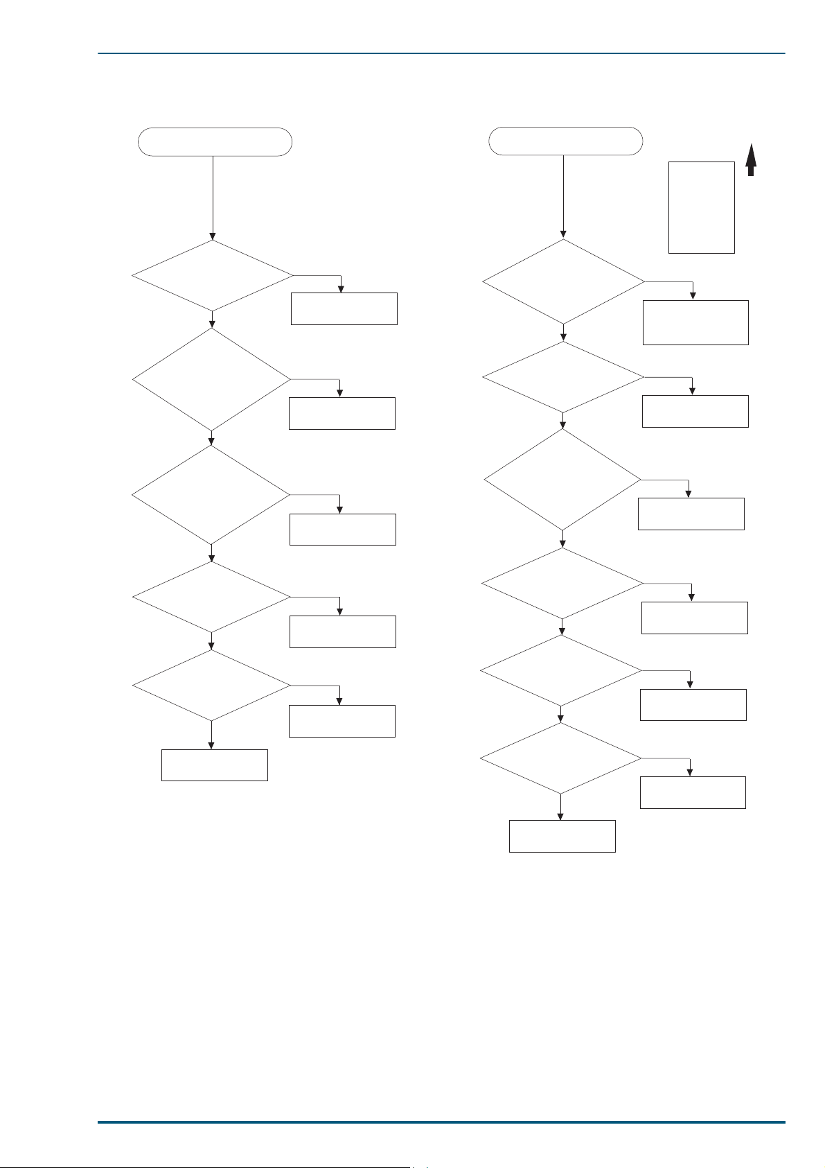
9.4.3 Missing Primary Colour 9.4.4 Light Print
Check again.
Paper Travel
N
Y
Correct connection
to the second bias
transfer roller.
Is the high
voltage connector to the
second bias transfer
roller normal?
Light Print
N
Y
Clean the path.
Is the path laser
beam travels
clean?
N
Y
Check the toner
cartridge selector.
Is the
toner cartridge
selector pushing the
toner cartridges into full
contact with
the belt?
N
Y
Replace the
imaging unit.
Is the imaging
unit normal?
N
Y
Replace the second
bias transfer roller.
Is the second
bias transfer
roller normal?
N
Y
Replace the fuser.
Is the fuser
normal?
Missing Primary Colour
9. Troubleshooting
Is the toner
cartridge of the
missing color
normal?
Y
Is the cable
from the cartridge
selector to the engine
control board (CN21)
normal?
Y
Is the toner
cartridge selector pushing
the toner cartridge into
contact with the
belt?
Y
Is the toner
cartridge drive
unit normal?
Y
*Is the engine
control board
normal?
Y
N
Replace the toner
cartridge.
N
Replace the cable.
N
Check the toner
cartridge selector.
N
Repair the toner
cartridge drive unit.
N
Replace the engine
control board.
Check again.
*
When replacing the Engine Control Board,
remove EEPROM (IC6) from the original Engine
Control Board and install it on the new Engine
Control Board.
113
Page 13

FS-5900C Service Manual
9.4.5 Repeated spots or lines on print
in-line with each other.
Repeated spots or lines on
print in-line with each other.
*
Measure the spacing
between the spots ( or
thin horizontal lines)
Paper Travel
Space Possible cause and remedy.
1.5 mm
26 mm
(1200 dpi)
34 mm
(600 dpi)
76 mm
Imaging unit gears poorly meshing.
Replace the imaging unit.
Replace the toner cartridge.
Replace the toner cartridge.
Replace the second bias transfer
roller.
9.4.6 Dark Vertical Line in Pr int
Dark Vertical Line
in Print
P
Is the scorotron
charger normal?
Y
Is the OPC belt
normal?
Y
Is the dark line of
one primary colour?
Y
N
Replace the
scorotron charger.
N
Replace the
Imaging unit.
N
Replace the toner
cartridge.
Paper Travel
94 mm
103 mm
125 mm
*
The distance between the repeating spots
indicates the source of the problem.
Thin horizontal lines, depending on problem,
the distance between lines may range from
1.5mm between each line to 103mm between
each line.
Imaging unit belt defect. Replace
the imaging unit.
Paper feeder drive gear broken
tooth. Repair the paper feeder.
Fuser roller defect. Replace the
fuser.
Is the path laser
beam travels
clean?
Y
Is the imaging unit
normal?
Y
Is the fuser unit
normal?
Y
Check again.
N
Clean the path.
N
Replace the
imaging unit.
N
Replace the fuser
unit.
114
Page 14

9. Troubleshooting
N
Clean or replace
the charger.
Is the scorotron
charger normal?
Y
N
Replace that colour's
toner cartridge.
Is excess
printing in background
of one primary colour?
Y
N
Replace the high
voltage board.
Is the high voltage
board normal?
Y
Check again.
Dirty Background
N
Replace the
toner cartridge.
Is the toner
cartridge roller
normal?
Y
Partial Black Dots
N
Replace the
imaging unit.
Are the OPC belt
and accumulator
belt normal?
Y
N
Replace the
fuser unit.
Are the fuser
rollers normal?
Y
Check again.
9.4.7 White horizontal line or band in
all the colours of a print
White horizontal line or band
in all the colours of a print
Is the imaging unit
normal?
Y
Is the secondary
bias transfer roller
normal?
Y
Check again.
N
Replace the
imaging unit.
N
Replace the
secondary bias
transfer roller.
9.4.9 Dirty Background
9.4.8 Mis-transfer, missing portions
of toner
Mis-transfer, missing
portions of toner
Is the imaging unit
normal?
Y
Is the heat roller of
the fuser normal?
Y
Check again.
9.4.10 Partial Black Dots
N
Replace the
imaging unit.
N
Replace the fuser.
115
Page 15

FS-5900C Service Manual
9.4.11 Dark Irregular Streaks in All
Colours
Dark Irregular Streaks in All Colours
Is the waste toner
box of the imaging
unit normal?
Y
Check again.
N
Replace the
imaging unit.
9.4.13 Unfused or Partially Fused Printing
Unfused or Partially Fused Printing
Is the paper
in good condition and
appropriate for a laser
printer?
Y
Is the fuser normal?
Y
Check again.
N
Use appropriate
paper.
N
Replace the
fuser unit.
9.4.12 Ghosting
Ghosting
*1
Is the toner
cartridge normal?
Y
Check again.
*1
Ghosting with some images is unavoidable because
of the colour structure of the images. If a colour is
used at one part of the image area and the same
colour is used again at a later area, it is very possible
to get ghosting of the first image into the second
image area after one revolution of the toner cartridge
developer roller. This occurs because the charge that
is created from the first use of the colour was not
totally extinguished, a small residual charge remains
associated with the colour, resulting in the second
use of the colour to be darker in the same areas as
the first image resulting in the first image ghosting
into the second image when the same colour is
issued.
*2
A new toner cartridge exhibits less ghosting.
Ghosting increase as toner cartridges age.
*3
When replacing the Engine Control Board, remove
EEPROM (IC6) from the original Engine Control
.
Board and install it on the new Engine Control Board
N
*2
Replace the
toner cartridge.
9.4.14 Image is skewed on the paper.
Image is skewed on the paper.
Is the paper feed unit
installed?
Y
Are the intermediate
and registration rollers
normal?
Y
Is the engine control
board normal?
Y
Check again.
N
Install the paper
feed unit properly.
N
Repair the paper
feed unit.
N
*3
Replace the engine
control board.
116
Page 16

9. Troubleshooting
N
Install the paper
feed unit properly.
Is the paper feed unit
properly installed?
Image is not centered on the
print when it should be.
N
Clean the rollers.
Are the intermediate
and registration rollers
clean?
Y
N
Check the paper
feed unit .
Is the paper feed unit
normal?
Y
N
Adjust the print
position
(section 7.1).
Is the print position
calibration correct?
Y
Y
N
Replace the
engine control
board.
Is the engine control
board normal?
Check again.
Y
*
*
When replacing the Engine Control Board, remove
EEPROM (IC6) from the original Engine Control Board
and install it on the new Engine Control Board.
9.4.15 Stains on Back of Print
Stains on Back of Print
Is the second bias
transfer roller
clean?
Y
Is the paper path
of the paper feed
unit clean?
Y
Are the fuser
rollers normal?
Y
Is
Fuser cleaning pad
clean?
Y
Check again.
N
Clean the roller
with a dry, lint free
cloth.
N
Clean the paper
path of the paper
feed unit.
N
Replace the fuser
unit.
N
Clean fuser
cleaning pad
9.4.17 Image is not centered on the
print when it should be.
9.4.16 No Printing on Edge of Print
No Printing on Edge of Print
Is a single primary
colour is missing?
Can each toner
cartridge be moved
forward normally toward
the imaging unit?
metal pads on the end
of the toner cartridge
Y
Y
Are the two
normal?
Y
N
Replace that colour's
toner cartridge.
N
Check the toner
cartridge selector.
N
Replace the toner
cartridge.
Are the cams of the
toner cartridge selector
normal?
Y
Check again.
N
Repair the toner
cartridge selector.
117
Page 17

FS-5900C Service Manual
9.5 Printer Error (Call Service person)
9.5.1 BB/B8/B9/BA
LCD Message Possible Cause
Call Service person BB
Call Service person B8
Call Service person B9
Call Service person BA
Black developing unit movement error
Cyan developing unit movement error
Magenta developing unit movement error
Yellow developing unit movement error
Push the error
developer towards
the OPC and check
that it moves.
Y
Does Developer
Cam of door move
normally in power
on initializing?
(Please compare with other
developers.)
(When door is opened, manually
depress the +24 V interlock switch
Y
turned on.)
N
Replace developer.
N
Replace Cam Motor & Cam
Gear Unit.
Is the same message
still displayed on the
LCD?
Y
Replace guide rail for
developer.
Is the same message
still displayed on the
LCD?
Y
Is the same message
still displayed on the
LCD?
Y
N
N
N
Is the cable for Cam
Motor Unit damaged?
N
*
Replace engine control
board.
*
When replacing the Engine Control Board, remove EEPROM (IC6) from the original Engine Control Board and
install it on the new Engine Control Board.
Y
Replace the cable.
Is the same message
still displayed on the
LCD?
Y
118
N
OK
Page 18

9.5.2 A6
LCD Message Possible Cause
Call Service person A6
Fuser/Toner Cartridge fan
error for Developer Unit
Fuser/Toner Cartridge fan is not rotating at normal
speed.
9. Troubleshooting
9.5.3 E2/E3
Call Service person E2
Call Service person E3
Check the connection
between engine control board
and LSU.
Is +24V outputted to
CN24 pins No.1 and
No.2 on the engine
control board?
Y
Replace the Fuser/Toner
Cartridge fan.
N
*
When replacing the Engine Control Board, remove
EEPROM (IC6) from the original Engine Control Board
and install it on the new Engine Control Board.
*
Replace the engine control board.
LCD Message Possible Cause
Scanner motor is not phase-locked and is not rotating at normal speed.
L-Sync Signal is not detected after APC, or Irregular L-Sync signal is
detected.
Check : Is the error message still displayed on the LCD?
Are the cables
connected
correctly?
Y
*
Replace the engine control
board.
Check
Y
End
N
N
Connect them correctly.
*
When replacing the Engine Control
Board, remove EEPROM (IC6) from
the original Engine Control Board and
install it on the new Engine Control
Board.
Replace LSU.
Y
Check
N
Check or replace the cables.
Check
Y
End
N
119
Page 19

FS-5900C Service Manual
9.5.4 A5
LCD Message Possible Cause
Call Service person A5 1. Abnormal spark discharge of Charger.
Check the charger unit.
2. Short circuit of FTR or DEV output.
Is the charger wire
cut?
N
Check the imaging unit.
Is the imaging unit
locked to Engine
firmly?
Y
Check the connection
between engine control board
and high voltage board (HVB).
Is the cable
connected
correctly?
Y
N
N
Replace charger unit.
Lock the imaging unit.
Connect it correctly.
Check
N
Check
N
Check
Y
Y
Y
120
Y
Check the connection of
charger or grid wire and each
output terminal.
Are they OK?
Y
12
N
N
Replace the output wire or
the output terminal.
Check
N
Y
Page 20

12
Check for a short circuit of
the FTR and DEV.
9. Troubleshooting
Is each of them
shorted to F.G.?
N
Replace the high voltage
board (HVB).
Check
N
Replace the engine control
*
board.
Check
Y
Y
Replace the output wire or
the output terminal.
Y
Check
N
Y
N
Replace the imaging unit.
* When replacing the Engine Control Board, remove EEPROM (IC6) from the original Engine Control
Board and install it on the new Engine Control Board.
OK
121
Page 21

FS-5900C Service Manual
9.5.5 AC
LCD Message Possible Cause
Call Service person AC OPC asynchronous with accumulator belt.
Check the imaging unit.
OPC home number and accumulator belt home number are not
synchronous.
Is the imaging unit
locked to Engine
firmly.
Y
Check the connection
between engine control
board and imaging unit.
Is the cable
connected
correctly?
Y
Check the connection between
engine control board and the
accumulator belt home sensor
board.
Is the cable
connected
correctly?
N
N
Lock the imaging unit.
Connect it correctly.
N
Connect it correctly.
Check
N
Check
N
Check
Y
Y
Y
122
Y
Check the accumulator belt
home sensor board.
Is the sensor
board gap clean?
Y
34
N
N
Clean the gap.
Check
N
Y
Page 22

34
Replace the imaging unit.
9. Troubleshooting
Check
N
*
Replace the engine control
board.
Check
N
•
Replace the cable between engine control
board and imaging unit.
•
Replace the sensor board and cable.
*
When replacing the Engine Control Board, remove EEPROM (IC6) from the original Engine Control
Board and install it on the new Engine Control Board.
Y
Y
OK
123
Page 23

FS-5900C Service Manual
9.5.6 AD
LCD Message Possible Cause
Call Service person AD OPC home is not detected within 4.5 sec during the
Check the color imaging unit.
main motor rotates.
Is the imaging unit
locked.
Y
Check the connection
between engine control board
and imaging unit.
Is the cable
connected
correctly?
Y
Replace the imaging unit.
Check
N
N
Y
Lock the imaging unit.
Connect it correctly.
Check
N
Check
N
Y
Y
N
*
Replace the engine control
board.
Check
N
Replace the cable between
engine control board and
imaging unit.
124
*
When replacing the Engine Control Board, remove
EEPROM (IC6) from the original Engine Control Board
and install it on the new Engine Control Board.
Y
OK
Page 24

9.5.7 AE
LCD Message Possible Cause
Call Service person AE Position error of the intermediate transfer unit
Position error of the
intermediate transfer unit
9. Troubleshooting
Does Main Motor
rotate?
Y
Is the imaging unit
locked in the
printer?
Y
Is the home sensor
case dirty with
toner?
N
N
Y
N
Y
Are motor control
signals sent from
engine control
board?
Y
Replace the Motor.
Is the error
message still
displayed on the
LCD?
Lock the unit in the printer.
Clean the case.
N
*
Replace engine control
board.
N
Is the error
message still
displayed on the
LCD?
Y
Is the error
message still
displayed on the
LCD?
Y
N
N
Replace the imaging unit.
*
When replacing the Engine Control Board, remove
EEPROM (IC6) from the original Engine Control Board
and install it on the new Engine Control Board.
Replace the Home Position
Sensor Board.
Is the error
message still
displayed on the
LCD?
Y
*
Replace Engine Control
Board.
Is the error
message still
displayed on the
LCD?
Y
N
N
OK
125
Page 25

FS-5900C Service Manual
9.5.8 AF
LCD Message Possible Cause
Call Service person AF Cleaning blade movement error
Replace imaging unit.
Is the same message
still displayed on the
LCD?
Y
*
Replace engine control board.
Is the same message
still displayed on the
LCD?
Y
Replace cleaning board.
Is the same message
still displayed on the
LCD?
N
*
When replacing the Engine Control Board, remove
EEPROM (IC6) from the original Engine Control Board
and install it on the new Engine Control Board.
N
N
Replace cleaning cam.
126
Y
OK
Page 26

9.5.9 B7
LCD Message Possible Cause
Call Service person B7 Paper transfer roller movement error
Paper transfer roller
movement error
9. Troubleshooting
Is the transfer roller
in the lower
position at the first
stage?
Y
Is the transfer roller
position sensor arm
broken?
Y
Does the transfer
roller clutch work
normally?
(Are the spring and the armature
installed properly?)
Y
Does the paper feed
unit board work
normally?
(Is the connector connected
Y
correctly?)
N
Set the transfer roller in the
normal (lower) position.
N
N
N
Change the transfer roller
position arm.
Replace the transfer roller
clutch.
Replace the paper feed until
board and reconnect the
connector.
Is the same message
still displayed on the
LCD?
Y
Is the same message
still displayed on the
LCD?
Y
Is the same message
still displayed on the
LCD?
Y
Is the same message
still displayed on the
LCD?
Y
N
N
N
N
*
Replace the engine control
board.
*
When replacing the Engine Control Board, remove EEPROM (IC6) from the original
Engine Control Board and install it on the new Engine Control Board.
OK
127
Page 27

FS-5900C Service Manual
9.5.10 A2
LCD Message
Call Service person A2 1. Fuser temperature is over 210˚C
A2 is displayed on the LCD.
Is the voltage
between pin9 and
10 (CN25 ) 0V?
N
Is pin9 (CN1) or
pin1 (CN301) a
low level?
Y
*
Replace the engine control
board.
Y
N
*
When replacing the Engine Control Board, remove EEPROM (IC6)
from the original Engine Control Board and install it on the new Engine
Control Board.
Is the thermistor
shortcircuited?
Replace the power supply.
Possible Cause
Y
N
Check the harness between
CN25 and the thermistor.
Replace the thermistor.
128
Page 28

9. Troubleshooting
LCD Message
Call Service person A2
A2 is displayed on the LCD.
Is the resistance
between CN204 pins
No.1 and No.3 10Ω
or less?
N
Is the thermostat
or the thermal fuse
open?
N
Possible Cause
2.
Fuser temperature does not reach 100˚C within 200sec,165˚C within 500sec during warming
up, or it is less than 120˚C during standby, and it does not return to set temperature within
100 sec after the low temperature error occurred during printing.
Y
Y
Does the thermistor
contact the heat
roller properly?
N
Replace the fuser unit.
Y
Replace the low voltage power
supply.
Repair or replace
the thermistor.
Check the following
connections:
1.Heater lead and drawer
connector lead.
2.Drawer connector lead and
thermostat terminal.
3.Thermostat terminal and
thermal fuse terminal.
4.Thermal fuse terminal and
heater lamp lead.
N
Repair or replace connections.
Y
Is the resistance of
N
the heater open?
Y
Replace the fuser unit drawer
connector.
Replace the fuser heater.
129
Page 29

FS-5900C Service Manual
9.5.11 E4
LCD Message Possible Cause
Call Service person E4 Fuser thermistor is disconnected.
E4 is displayed on the LCD.
9.5.12 A7
Is CN25 connected
properly?
Y
Is the resistance
between CN25 pins
NO.9 and NO.10
123KΩ (20°C )
or less?
Y
*
Replace the engine control
board.
*
When replacing the Engine Control Board, remove
EEPROM (IC6) from the original Engine Control Board and
install it on the new Engine Control Board.
N
N
Connect CN25 properly.
Is the thermistor
normal?
Y
N
Replace the thermistor.
Check the connection
between CN25 and the
thermistor, then repair or
replace it.
130
LCD Message Possible Cause
Call Service person A7 Power supply fan is not rotating at normal speed.
A7 is displayed on the LCD.
Is 24V outputted
between pin 1 and
pin 2 at CN30.
Y
Replace the power supply
cooling fan.
N
Replace the power supply.
Page 30

9.5.13 A8
9. Troubleshooting
LCD Message Possible Cause
Call Service person A8 Ozone fan is not rotating at normal speed.
Ozone fan error
Is +24V outputted
between CN9 pins
No.1 and No.2 on
the engine control
board ?
Y
Replace the ozone fan.
N
*
*
Replace the engine control board
When replacing the Engine Control Board, remove
EEPROM (IC6) from the original Engine Control Board
and install it on the new Engine Control Board.
.
131
Page 31

FS-5900C Service Manual
9.5.14 AA
LCD Message Possible Cause
Call Service person AA Toner cartridge drive motor (sleeve motor) unlocked
Replace developer unit.
*
When replacing the Engine Control Board, remove
EEPROM (IC6) from the original Engine Control
Board and install it on the new Engine Control
Board.
*
Replace engine control
board.
Is the same message
still displayed on the
LCD?
Y
Is the same message
still displayed on the
Replace imaging unit.
Is the same message
still displayed on the
N
Is the motor cable
damaged?
Replace the cable.
N
LCD?
Y
N
LCD?
Y
Y
N
Is the same message
still displayed on the
LCD?
Y
Replace the toner cartrdige
drive motor (sleeve motor).
Is the same message
still displayed on the
LCD?
Y
Replace the gear unit.
N
N
OK
132
Page 32

9.5.15 AB
LCD Message Possible Cause
Call Service person AB Paper feed motor unlocked
9. Troubleshooting
Does the paper
feed motor rotate
smoothly?
Y
Does the gear of the rear
chassis rotate normally?
Y
Does the gear of the paper
feed unit rotate normally?
Y
Does the gear of fuser
rotate normally?
Y
N
Replace the paper feed
motor.
Is the same message
still displayed on the
LCD?
N
Y
N
Replace the gear having the
problem.
Is the same message
still displayed on the
LCD?
N
Y
Replace the gear having the
N
problem and check the
rotation system of the paper
feed unit.
Is the same message
still displayed on the
LCD?
N
Y
N
Replace the gear having the
poblem and check the
rotation system of the fuser.
Is the same message
still displayed on the
LCD?
N
Y
Does the gear of the
toner cartridge unit
rotate normally?
N
Replace the gear having the
poblem and check the rotation
system of the selector / papereject unit.
Y
Is the cable for the
motor damaged?
Y
Replace the cable.
N
Replace imaging unit.
*
When replacing the Engine Control Board, remove
EEPROM (IC6) from the original Engine Control Board
and install it on the new Engine Control Board.
Is the same message
still displayed on the
Is the same message
still displayed on the
Is the same message
still displayed on the
*
Replace the engine control
board and check the
connection of the connector.
N
LCD?
Y
N
LCD?
Y
N
LCD?
Y
OK
133
Page 33

FS-5900C Service Manual
9.5.16 E1
LCD Message Possible Cause
Call Service person E1 Main motor unlocked
Is the imaging kit
installed
properly?
Y
Do the OPC belt and the
Transfer belt of imaging
unit rotate?
Y
Does the main
motor work
normally?
Y
Is the connector of
main motor cable
connected
properly?
Y
N
N
Install it properly.
N
Replace the imaging unit.
N
Replace the main motor.
Connect it properly.
Is the same message
still displayed on the
LCD?
Y
Is the same message
still displayed on the
LCD?
Y
Is the same message
still displayed on the
LCD?
Y
Is the same message
still displayed on the
LCD?
Y
N
N
N
N
Is the main motor
cable damaged?
N
*
Replace the engine control
board.
*
When replacing the Engine Control Board, remove EEPROM (IC6) from the
original Engine Control Board and install it on the new Engine Control Board.
Y
Replace the cable.
Is the same message
still displayed on the
LCD?
Y
N
OK
134
Page 34

9.5.17 A9
9. Troubleshooting
LCD Message Possible Cause
Call Service person A9 Multi-purpose pickup roller movement error
9.5.18 E6
Multi-Purpose Pickup Roller
Movement error.
Does the Multi-
Purpose Pickup
Roller Shaft
rotate?
Y
*
Replace the paper feeder
unit board or engine control
board.
*
When replacing the Engine Control Board,
remove EEPROM (IC6) from the original
Engine Control Board and install it on the
new Engine Control Board.
N
LCD Message Possible Cause
Call Service person E6 Engine Program ROM checksum error
Repair the retard pad.
N
Is the retard pad
able to move up
and down?
Y
Is the multi-
purpose feed motor
fixed to metal plate
properly?
Y
N
Fix to metal plate properly.
Replace the paper feeder
unit board or engine control
board.
9.5.19 BC
Engine Program ROM
checksum error occurs.
Replace the Engine Program
ROM.
LCD Message Possible Cause
Call Service person BC Engine SRAM check error
Engine SRAM check error
occurs.
Replace the Engine SRAM.
135
Page 35

FS-5900C Service Manual
9.5.20 BD
Call Service person BD Engine EEPROM check error
Engine EEPROM check error
occurs.
Replace the Engine
EEPROM.
9.5.21 E0
LCD Message Possible Cause
Call Service person E0
LCD Message Possible Cause
Communication Error of Printer Main Control Board
and Engine Control Board.
Is the cable between
Engine Control Board
and Printer Main Control
Board connected
properly?
Y
Is the Engine
Control Board OK?
Y
Is the Printer Main
Control Board OK?
Y
N
N
N
Connect the Engine cable securely.
Recheck.
*1
Replace the Engine Control Board.
Recheck.
Recheck.Recheck.
*2
Replace Printer Main Control Board.
Recheck.
End
*1
When replacing the Engine Control Board, remove EEPROM (IC6) from the original Engine Control Board
and install it on the new Engine Control Board.
136
*2
When replacing the Printer Main Control Board, remove IC9 from the original Printer Main Control Board
and install it on the new Printer Main Control Board.
Page 36

9.5.22 BE 9.5.23 BF
Connect CN25 properly.
Set the fuser unit properly.
Connect CN601 properly.
EEPROM (fuser unit) Error
Is CN25 connected
properly?
Is the fuser unit set
in the printer
properly?
Is CN601
connected
properly?
N
Y
Y
Call Service person
BF
EEPROM (fuser unit) Error
LCD Message Possible Cause
N
N
Call Service
person F0
Controller board system lock
error.
OK?
N
Y
Check or replace Printer
Main Control Board or
Relay Board.
LCD Message
Possible Cause
*
End
When replacing the Printer Main Control Board, remove
System DIMM's from the original Printer Main Control Board
and install it on the new Printer Main Control Board.
*
Wiring between Main Controller
Board and Relay Board; or
Relay Board and Printer Panel.
LCD Message Possible Cause
Call Service person
BE
EEPROM (imaging unit)
Error
EEPROM (imaging unit) Error
9. Troubleshooting
Is CN10 connected
properly?
Y
Is the imaging unit
in the printer
properly?
Y
Is CN628
connected
properly?
Y
Replace the imaging unit.
OK?
N
Connect CN10 properly.
N
Set the imaging unit properly.
N
Connect CN628 properly.
9.5.24 Call Service person F0
N
*
End
*
When replacing the Engine Control Board, remove
EEPROM (IC6) from the original Engine Control Board
and install it on the new Engine Control Board.
Replace engine control
board.
137
Page 37

FS-5900C Service Manual
9.5.25 Memory Overflow
LCD Message Possible Cause
Memory Overflow Print data is larger than the capacity of the memory
Lower the resolution of the
printing image by using Print
Setup.
installed
OK?
Y
9.5.26 Call Service person F2
LCD Message Possible Cause
Call Service person F2
Replace Option SIMM(s).
N
RAM Read/Write Error
Add memory to the printer.
End
138
OK?
Y
END
N
Check or replace Printer Main
Controller Board.
Page 38

9.5.27 Call Service person F3
LCD Message Possible Cause
Call Service person F3
Turn printer power off,
then on again
9. Troubleshooting
An exceptional failure has occured during the task
management (such as a buss error).
OK?
Y
END
N
Check or replace Printer Main
Controller Board.
139
Page 39

FS-5900C Service Manual
9.6 No Message Section
Start
Power switch ON
Is the power
supply cooling fan
working?
Y
Check the voltage at CN301
of power supply unit at 5V,
5VIP, 24V.
N
Connect the AC cord, then
Is the AC cord
connected to the
printer?
Y
Check the voltage at CN201
of power supply unit.
Is the voltage 120V?
Y
Replace the power supply,
then repeat the procedure
from START.
N
repeat the procedure from
START.
N
Replace the AC cord, then
repeat the procedure from
START.
140
Are the voltages
normal?
Y
Check the display panel and
cables.
Is the display
panel OK?
Y
Exit
N
N
Replace the power supply,
then repeat the procedure
from START.
Replace display panel or
cables.
 Loading...