

Page 1
FS-5900C Service Manual
5. Removal and Replacement Procedures
Caution:
The imaging unit (OPC belt and accumulator belt) is extremely light sensitive. Make sure that
it is not exposed to li ght fo r more than 45 seconds , or it may da mage t he unit. Ne ver expose the
imaging unit to direct sunlight. When servicing the printer, ensure that the imaging unit is not
exposed to light. If necessary, remove it and store in a dark place.
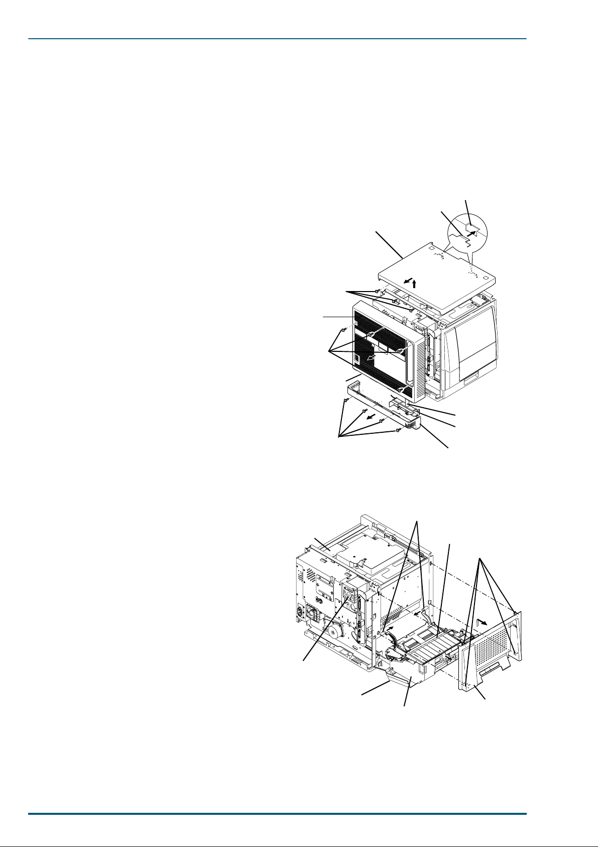
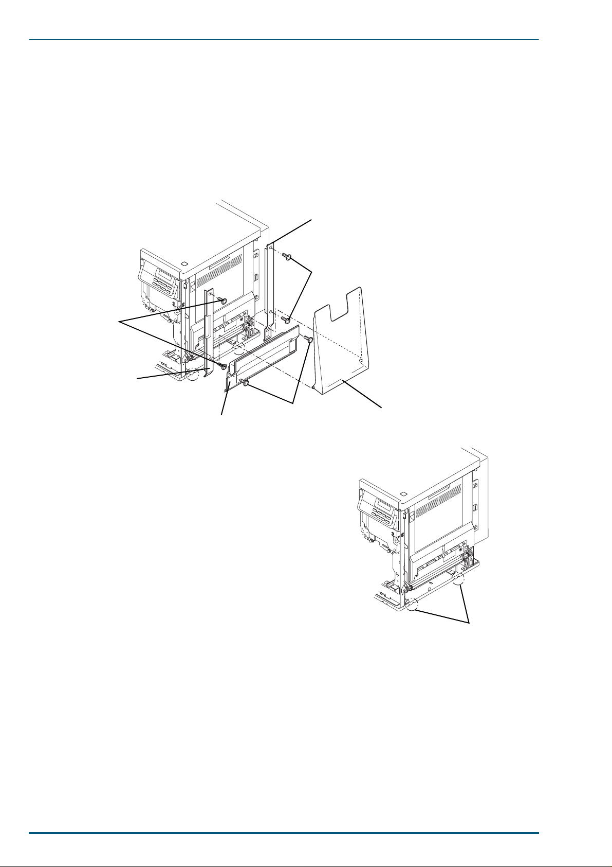
5.1 Upper Rear, Lower Rear and Top Covers
1. Remove the upper rear cover (4 screws).
2. Remove the lower rear cover (4 screws).
3. Separate the lower rear cover from the duct tube.
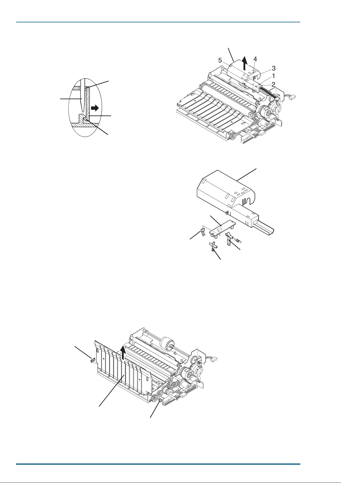
4. Remove the top cover (3 screws).
The front of the top cover is held by metal tabs.
Tilt the top cover up from the rear (arrow 1), slide it
back slightly (arrow 2), and remove it.
Screw
Fan
Cover
Screw
Upper Rear
Cover
Top Cover
~
A
C
I
N
Opening on
Chassis Frame
Metal Tab
2
1
5.2 Left Side Cover and Multi-purpose Tray
1. Remove the upper rear cover and top cover (See sec-
tion 5.1).
2. Open the left side cover.
3. Pull out the paper feed unit.
4. Lower the MP tray.
5. Remove the left side cover while releasing the 4
hooks from the printer f rame.
6. Remove the multi-purpose tray by sliding part A in
the direction indicated by the arrow.
Screw
Board
Fan
Cover
Left Side Cover
Part A
Multi-purpose Tray
Paper Feed Unit
Duct tube
Humidity
Sensor Case
Lower Rear Cover
Hook
Left Side
Cover
38
Page 2
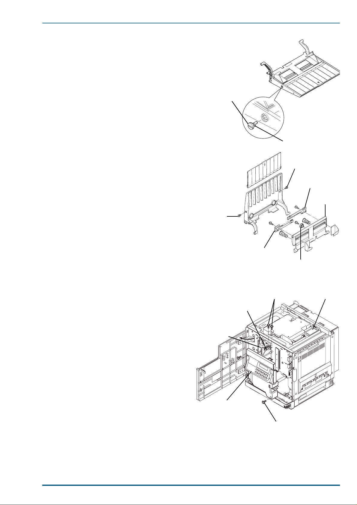
7. Turn the bushing 90 degrees counterclockwise.
Tab
Bushing
Bushing
Bushing
Rack
Paper
Support
Rack
Pinion Gear
Operation
Panel Cove r
Screw
Connector
Screws
Earth
Lead
Board
8. Remove the 2 bushings.
9. Separate the paper support assembly from the
holder.
10.Remove the pinion gear and racks (3 screws).
5. Removal and Replacement Procedures
Turn the bushing 90
degrees clockwis e or
counterclockwise.
5.3 Operation Panel Cover and Printer LCD Board
1. Remove the upper rear cover and top cover (See
section 5.1).
2. If the imaging unit is installed, remove it.
3. Open the front cover and remove the operation
panel cover assembly (3 screws).
4. Remove the 1 earth lead wires (1 screws).
5. Disconnect the connector.
39
Page 3
FS-5900C Service Manual
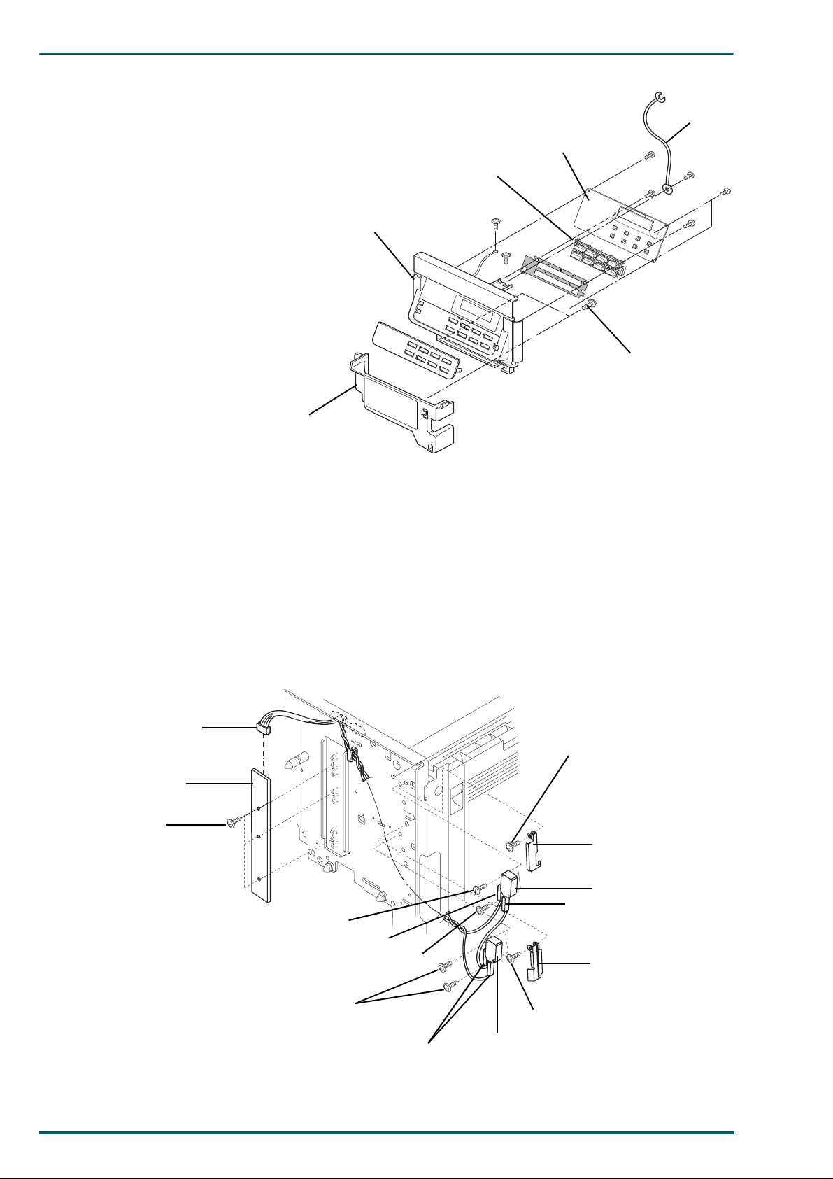
6. Remove the LCD board b racket (4
screws).
7. Remove the LCD board (6 screws).
8. Remove the operation button from the
operation panel cover.
9. Remove the lower operation panel cover
(2 screws).
Lower Operation
Panel Cover
Ground
Wire
LCD Board
Operation Button
Operation Panel Cover
Screw
5.4 Safety Interlock Switches and Toner Empty Sensor Board (T)
1. Remove the upper rear cover, top cover and operation panel cover (See section 5.1 and 5.3).
2. Remove the 3 screws and disconnect the connector on the toner empty sensor board.
3. Remove the toner empty sensor board.
4. Disconnect the 2 connectors from each of the 2 safety interlock switches.
5. Remove the 2 screws from each of the 2 safety interlock switches.
6. Remove the screw from each of the switch levers and switch lever.
Connector
Screw
Toner Empty
Sensor Board
Screw
Switch Lever
Safety Interlock Switch
Screw
Connector
Screw
Connector
Switch Lever
40
Screws
Connector
Screw
Safety Inter lo c k Switch
Page 4
5. Removal and Replacement Procedures
Parts C
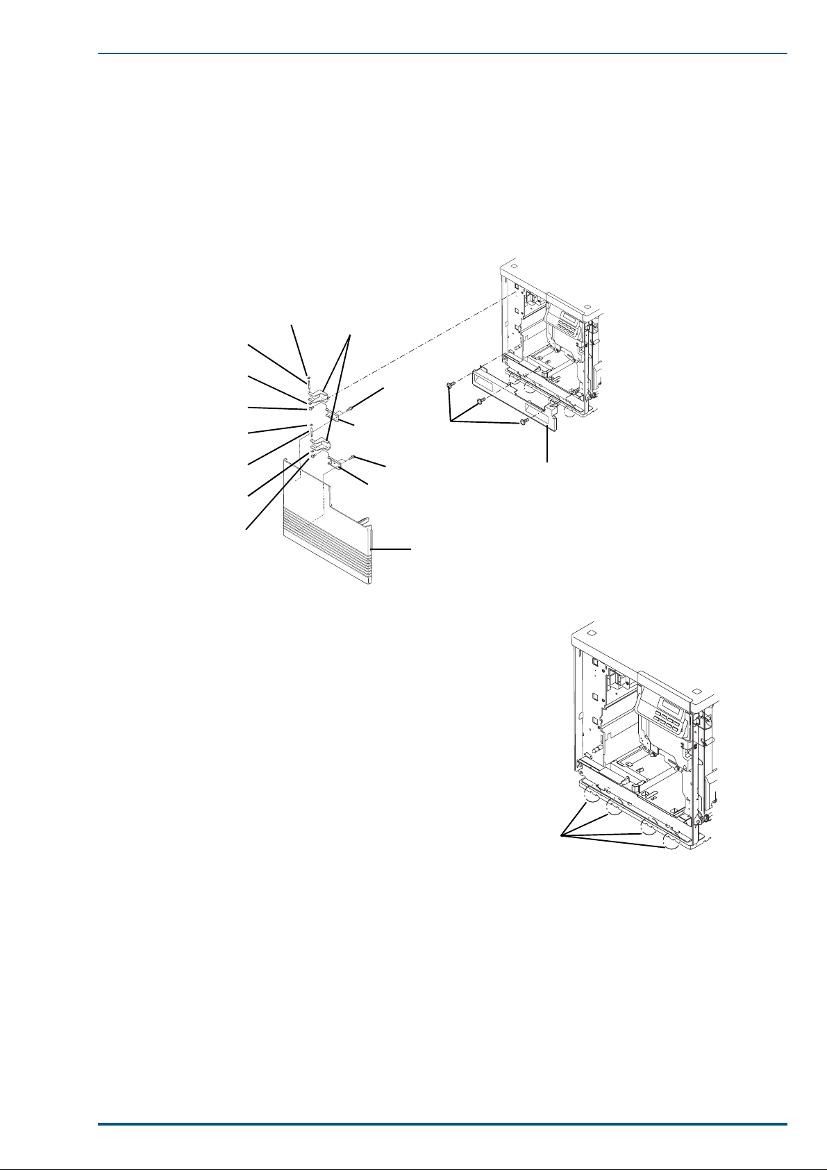
5.5 Front Cover and Bottom Front Cover
1. Open the front cover.
2. Remove the bottom front cover (3 screws).
3. Remove the front cover with hinges [4 screws (A)].
4. Remove the hinge assemblies from the front cover [4 screws (B)].
5. Remove the E-rings f rom the hinge shafts. The front cover hinges can now be separated from the front
cover hinge supporters.
Note:
E-ring
Hinge Shaft
E-ring
Screw (A)
E-ring
Hinge Shaft
E-ring
Screw (A)
Front Cover Hinge
Screw (B)
Front Cover
Hinge Supporter
Screw (B)
Front Cover
Hinge Supporter
Front Cover
The bottom front cover is latched by metal tabs
(Parts C below). When removing or reinstalling
this cover, it must be released from the tabs or
latched with the tabs.
Screw
Bottom
Front Cover
41
Page 5
FS-5900C Service Manual
5.6 Front Right Side, Rear Right Side and Lower Right Side Covers
1. Remove the bottom front cover (See section 5.5).
2. Remove the paper exit tray.
3. Remove the front right side cover (2 screws).
4. Remove the rear right side cover (2 screws).
5. Remove the lower right side cover (2 screws).
Rear Right Side Cover
Screw
Screws
Front Right Side Cover
Note:
The lower right side cover is latched by metal
tabs (Parts A below). When removing or reinstalling this cover, it must be released from the tabs or
latched with the tabs.
Lower Right Side Cover
Screws
Paper Exit Tray
Parts A
42
Page 6
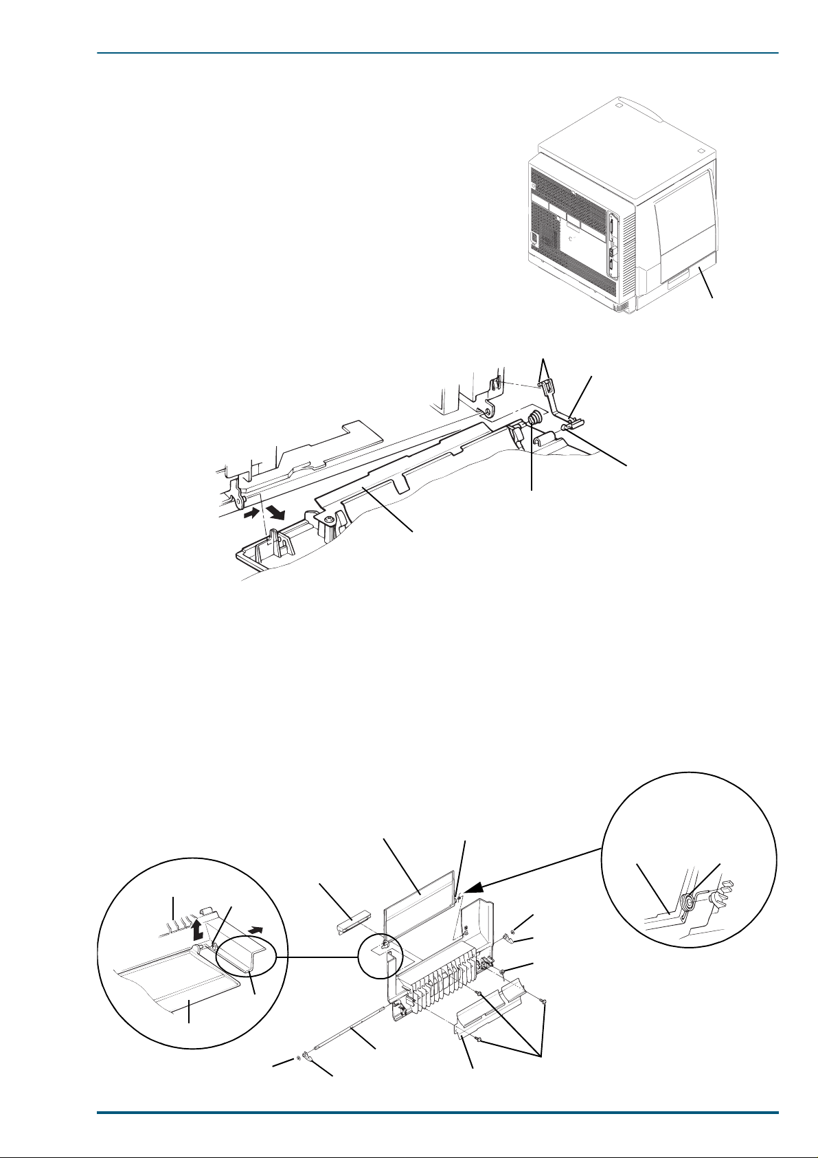
5.7 Left Side Cover
Left Side Cover
5.7.1 Left Side Cover Re moval
1. Open the left side cover.
2. Remove the black strap by releasing the hooks.
3. Remove the left side cover by sliding it in the direc-
tion of arrows 1, 2.
5. Removal and Replacement Procedures
Hook
Strap
Hook
2
1
Left Side Cover
Spring
5.7.2 Left Side Cover Sub Assembly
1. Remove the tray cover by sliding it in direction of arrow while slightly deflecting part (A) of left side
cover in the direction of arrow. Release the tray cover from the tab on the left side cover as shown in circle A below.
2. Remove the paper chute (2 screws).
3. Remove the tray cover lever (1 screw).
4. Remove the 2 E-rings and 2 door hooks.
5. Remove the left side cover shaft and shaft spring by pulling out the door shaft.
When reinstalling the tray
cover and the tray spring,
Tray SpringTray Cover
AAAA
Tray Cover Lever
Left Side Cover
Tab
E-ring
install the spring as shown
below.
Tray Cover Tray Spring
Tray Cover
Part (A)
E-ring
Left Side Cover Shaft
Door Hook
Paper Chute
Door Hook
Shaft Spring
Screw
43
Page 7
FS-5900C Service Manual
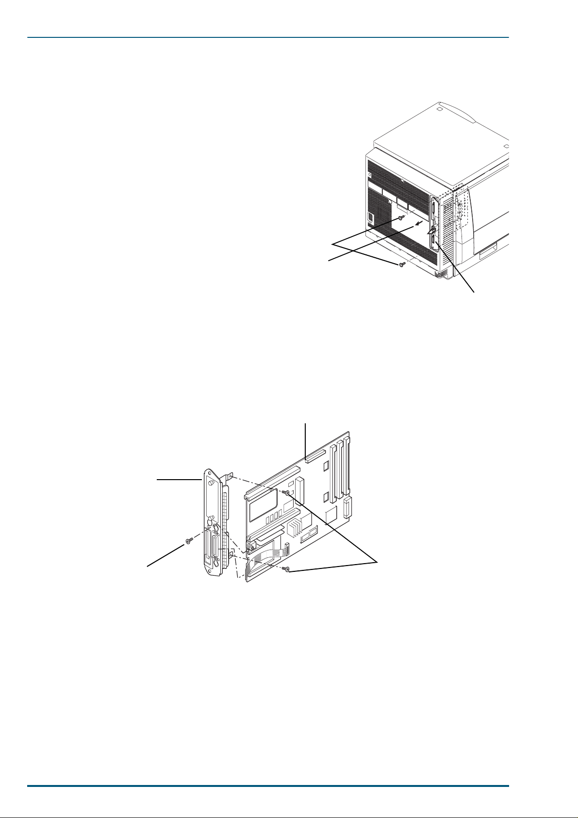
5.8 Printer Main Control Board, HSYNC Board and Network Relay Board
5.8.1 Printer Main Board Removal
1. Remove the cable cover (2 screws).
2. Disconnect the connector by pulling the tab.
3. Remove the 2 screws, then pull out the printer main
board.
Note:
When replacing the printer main board, the current EEPROM (IC9) must be installed on the new
board. If the EEPROM is damaged, the color density calibration must be reset. Refer to section
7.2.
Screws
Pull out
Printer Main
Control Board
5.8.2 Printer Main Control Board Disassembly , HSYNC Board and Network Relay
Board
1. Remove the 3 screws from the connectors.
2. Separate the main board bracket from the printer main control board.
Main Control Board
Main Board Bracket
Screw
Screws
44
Page 8
5. Removal and Replacement Procedures
Screw
Green Handle
Green Handle
Screw
Tabs
Square Opening
Paper Feed
Unit Cover
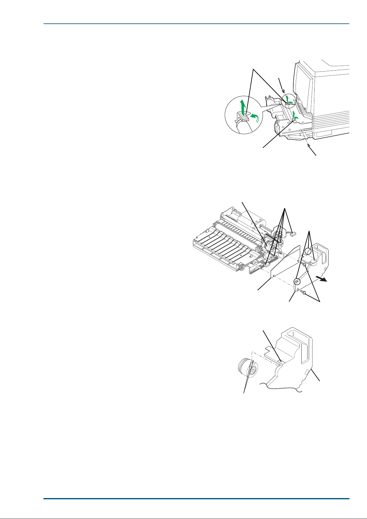
5.9 Paper Feed Unit
5.9.1 Paper Feed Unit Removal
1. Open the left side cover to access the paper feed unit.
2. Slide out the paper feed until it stops.
3. Push in on the tw o green tabs to unlock the paper
chute. Lift the paper chute until it catches, in the
open position.
4. Rotate the green handles on the transfer roller. Lift
out the transfer roller/waste bin (consumable) to
avoid toner spillage.
5. Remove the 2 screws.
6. Slide the paper feed unit off the rails.
5.9.2 Paper Feed Unit Board and MP Tray Paper Out/Registrati on Sensor Board
1. Remove the screw from t he paper feed unit
cover.
2. Remove the paper feed unit cover while releas-
ing the 3 hooks.
3. Remove the paper feed unit board (1 screw).
Registration Roller Clutch
Connector
3 Hooks
4. Disconnect the 4 connectors on the paper feed
Note:
unit board.
When reinstalling the paper feed unit
cover, the tabs of the registration roller clutch
must be aligned with the square opening.
Paper Feed
Unit Board
Paper Feed Unit
Cover Screw
Screws
45
Page 9
FS-5900C Service Manual
5. Remove the s e nsor case with the sensors after releas-
ing the 5 hooks in order
screwdriver below.
Flat Blade
Screwdriver
The MP tray paper out sensor, registration sensor and
MP tray Paper Out/reg. Sensor Board can now be
removed from the sensor case by releasing it from the
hooks.
1 to 5 using a flat blade
Opening of
Sensor Cover
Sensor Cover
Hook
Sensor Case
Sensor Case
Sensor Board
Connector
Registration Sensor Arm
MP Tray Paper Out
Sensor Arm
5.9.3 Transfer Roller Clutch, Transfer Roller Holder, Cleaning Roller Holder and
Registration Roller
1. Pivot the paper chute to an upright positio n.
2. Lift and remove the paper chute.
Bushing
46
Paper Chute
Bushing
Page 10
5. Removal and Replacement Procedures
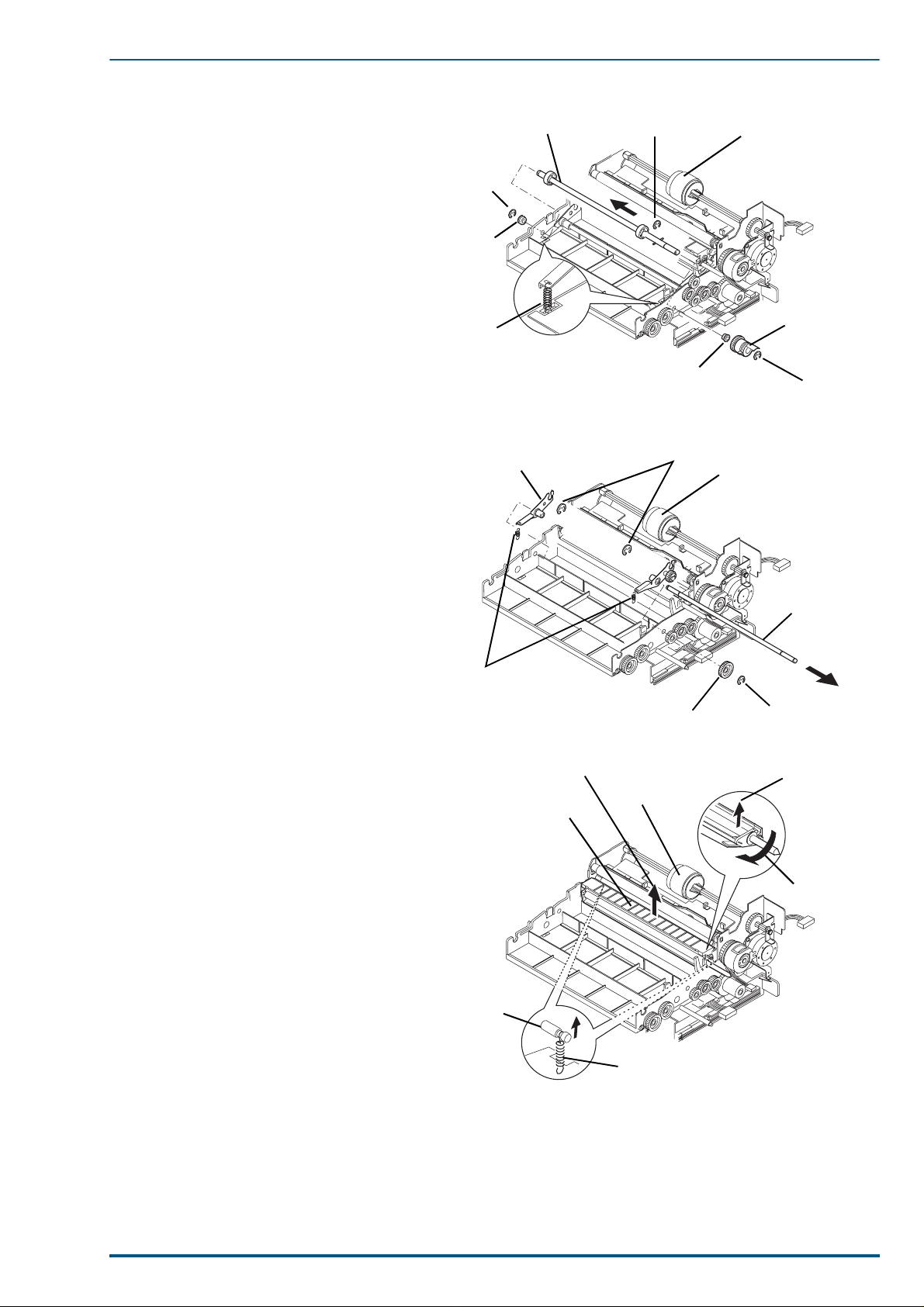
3. Remove the 3 E-rings and 2 springs from
the transfer roller cam shaft.
4. Remove the clutch, 2 bushings and
transfer roller cam shaft.
5. Remove the E-ring and gear from the
transfer roller holder shaft.
6. Remove the 2 E-rings, then slide out the
transfer roller holder shaft. The right
and left transfer holders can be removed.
Transfer Roller
Cam Shaft
E-ring
Bushing
Spring
Transfer Roller Holder
E-ring
Bushing
E-ring
Pickup Rollet
Clutch
E-ring
Pickup Rollet
7. Release the 2 springs from the spring
studs (located on back side of the paper
feed unit).
8. Rotate the cleaning roller holder up.
9. Lift and remove the cleaning roller
holder. The cleaning pressure roller and
2 bushings can be removed from the
holder.
Spring
Pull up
Cleaning Roller Holder
Stud
Gear
Pickup Rollet
Transfer Roller
Holder Shaft
E-ring
Pull up
Direction of
Rotation
Spring
47
Page 11
FS-5900C Service Manual
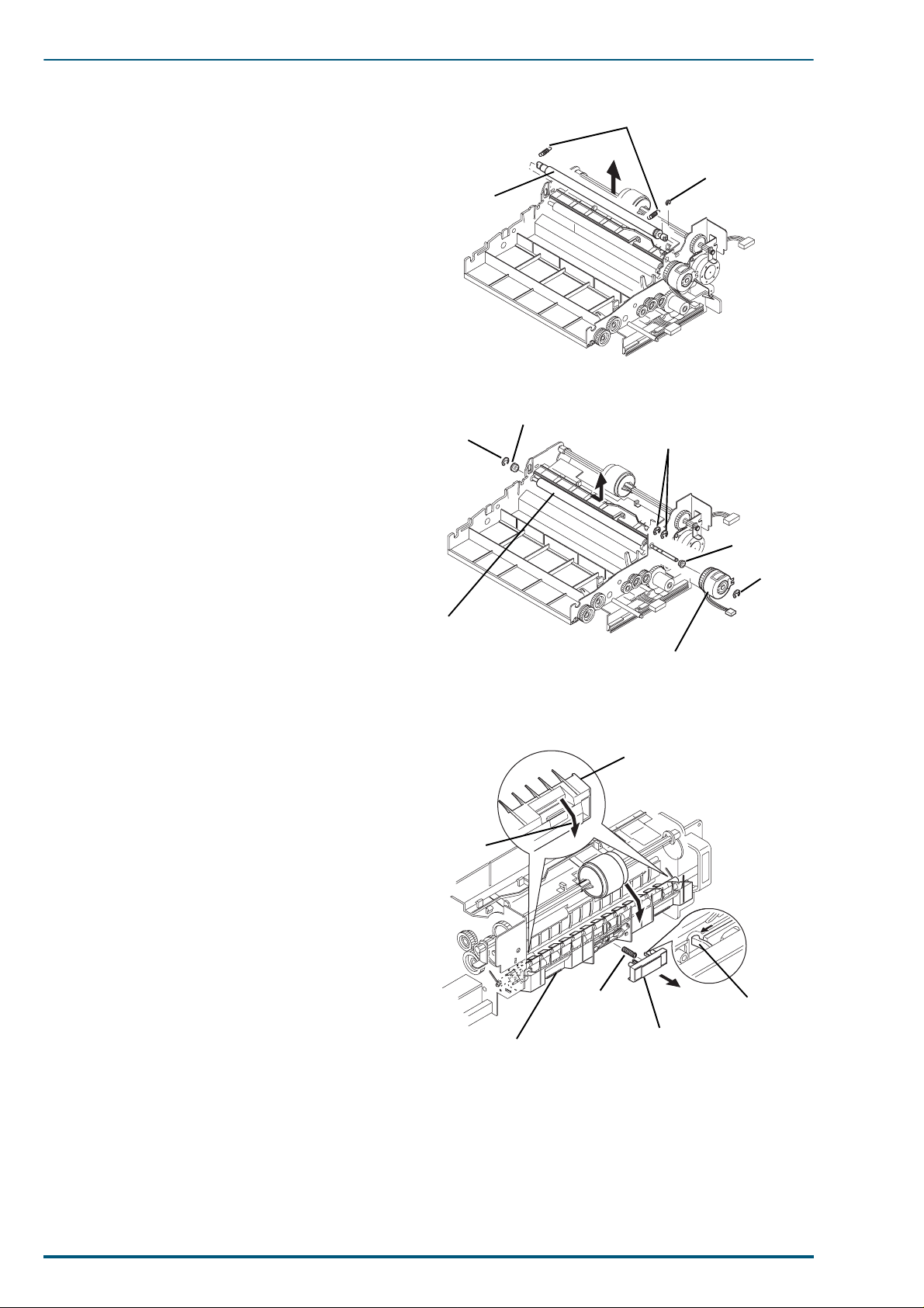
10.Remove the 2 springs and the plastic
clip.
11.Move the upper registration roller to the
right and remove.
12.Remove the 4 E-rings, 2 bushings and
registration roller clutch.
13.Remove the lower registration roller.
Upper Registration
Roller
E-ring
Springs
Plastic Clip
Bushing
E-rings
Bushing
5.9.4 MP Tray Retard Pad
Open the MP tray chute assembly with the
retard pad by sliding it in the direction of
arrow A.
Remove the retard pad by releasing the
hooks.
Lower Registration Roller
Arrow A
Registration Roller Clutch
MP Tray Chute Assembly
Spring
E-ring
Hook
48
MP Tray Chute Assembly
Retard Pad
Page 12
5. Removal and Replacement Procedures
Hook
MP Tray Pickup Roller
Pickup Roller
Guide
5.9.5 MP Tray Motor, MP Tray Pickup Roller and MP Tray Pickup Roller Shaft
Note:
When reinstalling the pickup roller and cam to the MP tray pickup roller shaft, the rubber side of
the MP tray pickup roller, cams and STR sensor arm must be positioned as shown below.
Cams
5.9.5.1 MP Tray Pickup Roller
Release the hook of the pickup roller guide roller
1.
from the MP tray pickup roller shaft.
2. Remove the E-ring and slide the pickup guide
roller in the direction indicated by the arrow.
Pickup Roller Rubber
STR Sensor Arm
3. Remove the MP tray pickup roller.
49
Page 13

FS-5900C Service Manual
5.9.5.2
Remove the motor bracket with the motor (2
1.
screws).
MP Tray
Motor and
MP Tray
Pickup Roller Shaft
2. Remove the 2 gears and STR sensor arm after
releasing the hooks.
3. Remove the 3 E-rings and 2 bushings from the
shaft.
4. Release the hooks of the pickup roller guide roll-
ers.
5. Move the pickup roller guide rollers and MP tray
pickup roller in the direction of the arrow.
E-ring
STR Sensor
Arm
Bushing
Screw
Gears
Screw
Bracket
E-ring
Bushing
6. Remove the MP tray pickup roller shaft assembly
by sliding it in the order of the arrows
(If necessary, remove the M.P.T pickup roller.)
1 to 2.
E-ring
Pickup Roller Guide
Rollers and Pickup
Roller
MP Tray Pickup
Roller Shaft
50
Page 14

5. Removal and Replacement Procedures
5.9.6 Pickup Roller, Pickup Roller Shaft Assembly and Paper Empty Sensor Arm
Note:
When reinstalling the pickup roller to the pickup roller shaft assembly with the clutch, the rubber
side of both pickup rollers, the pawl on the clutch, and part A of the pickup roller shaft must be positioned as shown below.
Pawl
1. Place the unit face down.
2. Remove the E-ring, then remove the pickup
roller by sliding it in the direction of the arrow.
Pickup Roller Rubber
Part A (D-shape)
E-ring
E-ring
3. Remove the E-ring and pickup roller shaft
assembly. If necessary, remove the pickup rollers.
4. Remove the paper empty sensor arm.
Paper Empty
Sensor Arm
Pickup Roller Shaft A ssemb ly
with Pickup Rollers
Pickup Rollers
Bushing
E-ring
51
Page 15

FS-5900C Service Manual
5.9.7 Paper Feed Roller and Paper Feed Unit Frame
Remove the following parts:
a. Paper Feed Unit Cover, Paper Feed Unit Board, Sensor Case (See section 5.9.2):
b. Transfer Roller Cam Shaft, Transfer Roller Holder Shaft, Cleaning
Roller Holder and Registration Roller (See section 5.9.3):
c. MP tray Motor and MP tray Pickup Roller Shaft (See se ction 5.9.5):
d. Pickup Roller Shaft and Paper Empty Sensor Arm (See section 5.9.6):
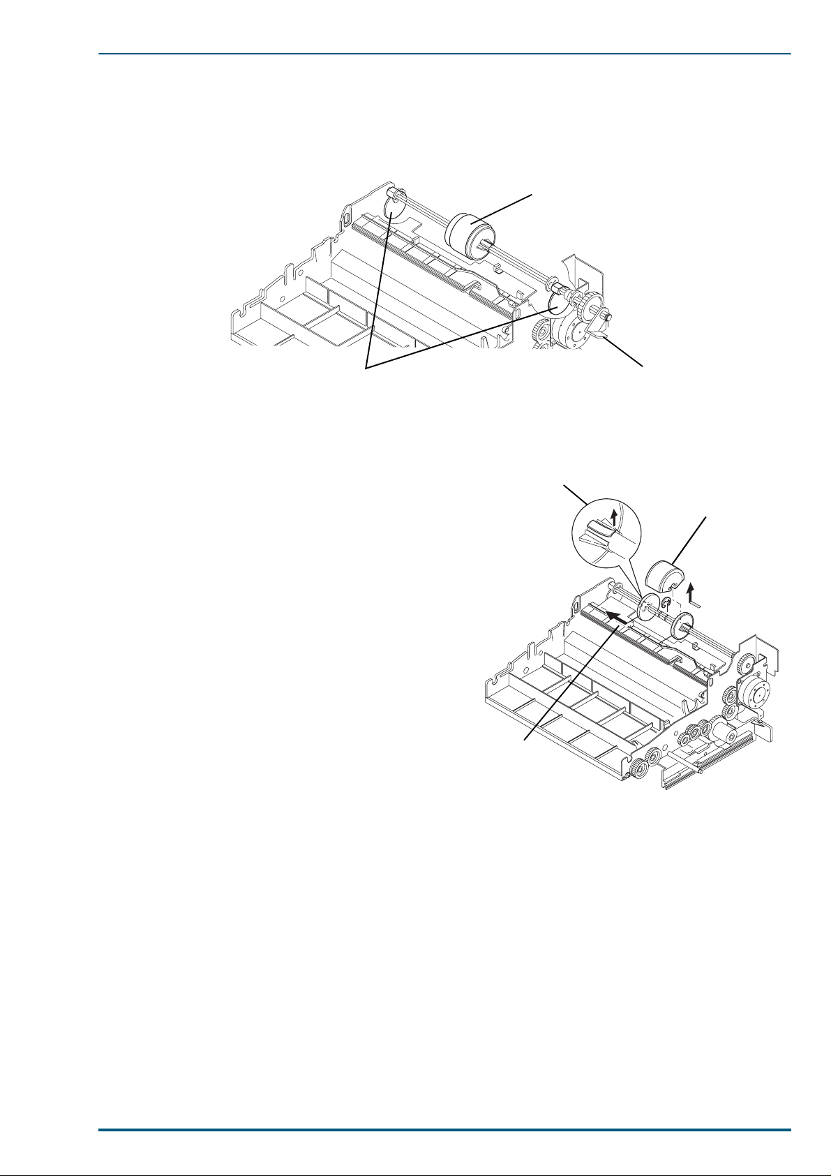
1. Remove the E-ring and gear from the
gear shaft.
E-ring
2. Remove the 3 E-rings, gear and 2 bush-
ings from the paper feed roller shaft.
3. Remove the 4 screws from the paper feed
unit frame.
4. Remove the paper feed unit frame from
the paper feed unit base.
5. Remove the paper feed rolle r from the
paper feed unit base.
6. Remove the spring and MP tray chute assem-
bly.
Bushing Paper Feed Unit Base
Gear Shaft
Roller Shaft
Spring
Paper Feed Unit Frame
Gear
E-ring
Bushing
Gear
Screws
Paper Feed Roller
MP Tray Chute Assembly
E-rings
7. Remove the 2 springs from the MP tray chute
assembly.
8. Remove the pinch roller assembly while dis-
torting the area (A) of the MP tra y Chute using
the (-) driver.
Spring
MP Tray Chute Asse mbly
Area (A)
Pinch Roller
Assembly
(–) Driver
52
Page 16

5. Removal and Replacement Procedures
E-rings
E-rings
Connector
90 to 130 mm
Toner Developer
Selector/Paper-eject
Unit
Spring
Spring
Stoppers
Spring
E-ring
Bushing
E-ring
Bushing
Support
Shaft
5.10 To ner Developer Selector/Paper-eject Unit
5.10.1 Toner Developer Selector/Paper-eject Unit Removal
1. Remove the paper exit tray, front right side cover,
lower right side cover, rear right side cover, bottom
front cover (See section 5.5 and 5.6).
2. Remove the 4 E-rings and disconnect the connector.
3. To relive spring tension open the toner developer
selector/paper-eject unit.
4. Slide the spring stoppers and springs in the direction
of the arrows to unlatch the springs from the printer
frame.
5. Close the unit.
6. Remove the 2 E-rings and 2 bushings.
7. Slide the support shaft to the right or left, and
remove the unit.
Note:
When reinstalling the toner developer selector/
paper-eject unit, remove the solenoid side cover
and motor side cover from the unit (See section
5.10.2.1). Reinstall the unit on the printer by per-
forming the procedure in reverse order.
53
Page 17

FS-5900C Service Manual
5.10.2 Covers, Sensor Boards (Paper Ejection, Paper Exit, Paper Tray Full) and
Paper Ejection Roller
5.10.2.1 Covers
Remove the spring stopper (right side) and spring (right side).
1.
2. Remove the 12 screws from the motor side cover, solenoid side cover and unit inner cover.
3. Remove the covers, spring stopper (left side) and spring (left side) .
Screw Screw
Unit Inner Cover
Spring Stopper (right side)
Screw
Spring Stopper (left side)
Spring (left side)
Solenoid Side Cover
Spring (right side)
ScrewsMotor Side Cover
4. Remove the unit cover (4 screws).
5. Release the 2 springs from the chassis frames and screw (A), then remove the unit face down cover and
paper tray full sensor arm.
Screw (A)
Spring
Spring
Unit Face Down Cover
Note:
Before reinstalling the unit cover, the unit face down cover should be installed.
54
Unit Cover
Screws
Plastic Wash er
Paper Tray Full Sensor Arm
Screw
Screw
Page 18

5. Removal and Replacement Procedures
5.10.2.2 Sensor Boards (Paper Ejection, Paper Exit, Paper Tray Full) and Paper Ejection
Roller
Sensor Boards (Paper Ejection, Paper Exit, Paper Tray Full)
Disconnect the connector on the paper tray full sensor board.
1.
2. Remove the paper tray ful l sensor board (1 screw).
3. Remove the 2 screws from the paper exit sensor board .
4. Disconnect the 3 connecto rs on t he pa per exit sens or boar d. The paper ex i t sensor b oar d can now be sep-
arated from the toner developer selector/paper-eject unit.
5. Remove the paper ejection sensor board (1 screw).
Paper Exit Sensor Board
Connector
Screws
Paper Ejection Roller
Remove the 2 E-rings and 2 bushings from the paper ejection roller.
1.
2. Remove the paper ejection roller.
Paper Tray Full Sensor Board
Connectors
Paper Ejection Roller
55
Page 19

FS-5900C Service Manual
5.10.3 Cam Motor Board, Toner Developer Movement Sensor Board and Toner
Selector Cam
1. Remove the motor side cover, solenoid side cover and
unit inner cover (See section 5.10.2.1).
2. Disconnect the 2 connectors, then remove the 3
screws from cam motor bracket.
3. Remove the cam motor bracket with the boards.
Connectors
4. Remove the 8 screws from the bracket and 2
screws from the cam motor board.
5. Remove the cam motor board with the motors.
6. Remove the 4 nuts from the 4 cam shafts, then
pull out the 4 cam shafts.
7. Remove the 4 cam gears.
8. Remove the toner developer movement sensor
board (3 screws).
9. Remove the 3 E-rings, gear, plastic
washer and 2 bushings from each shaft.
The toner selector cam and toner selector
shaft can now be removed.
Cam Motor Bracket
with board
Nut
Cam Gear
Cam Shaft
Cam Motor Boar d
E-ring
8 Screws
Screw
Cam Motor Bracket
Screw
Toner Developer
Movement Sensor
Board
Screws
56
Bushing
Toner Selector Cam
Spring Pin
Spring Pin
Bushing
Gear
E-ring
Page 20

5. Removal and Replacement Procedures
Selector Cam
Shaft
Short
Groove
Selector Cam Gear
Long Groove
Pin
Solenoid
Embossments
Direction
of Stroke
Note: When reinstalling the toner selector cam and
toner selector cam gear, make sure that the direction of the pin grooves for the cam and gear are
the same.
5.10.4 Joint Gear and Face Down Switch Back Solenoid
Note: When reinstalling the solenoid, fit the 2 hole s of
the solenoid to the positioning embossments, then
tighten the screws while pressing the solenoid to
the arrow direction. This allows minimum stroke
of the solenoid plunger.
1. Remove the motor side cover, solenoid side cover and unit inner cover (See section 5.10.2.1).
2. Remove the E-rings and spring.
3. Remove the joint gear.
4. Remove the 2 screws and face down switch back solenoid.
5. Disconnect the connector on the ADU Jam D sensor board.
Screws
Face Down Switch Back Solenoid
Spring
Joint Gear
Joint Gear Bracket
Gear
E-rings
6. Remove the 2 screws that secure the ADF gate solenoid.
7. Disconnect the connector on the paper tray full sensor board.
57
Page 21

FS-5900C Service Manual
5.10.5 Switch Back Shaft, Switch Back Roller and Face Down Switch Gate
1. Remove the motor side cover, solenoid side cover and unit inner cover (See section 5.10.2.1).
2. Remove the paper ejecti on roller (See section 5.10.2.2).
3. Remove the cam motor bracket with board and toner selector cam (See section 5.10.3).
4. Remove the cable bracket (2 screws).
5. Remove the E-ring from the switch back shaft.
6. Pull out the switch back shaft.
E-ring
Cable
Bracket
Switch Back Shaft
Pull Out
Switch Back Shaft
7. Remove the joint gear and face down switch back solenoid (See sectio n 5.10.4).
8. Remove the spring, plastic ring and switch back arm.
9. Remove the ADU Gate arm.
10.Remove the 4 E-rings, pin, 2 gears and 2 bushings from the right side chassis frame.
11.Remove the 2 E-rings and 2 bushings from the left side chassis frame.
Bushings
Plastic Ring
Screws
Bushing
E-rings
58
Spring
Switch Back Arm
E-ring
Bushing
Gear
E-ringE-ring
Gear
Pin
Page 22

5. Removal and Replacement Procedures
12.Remove the screw from the paper ejection guide.
13.Slide the paper ejection guide out in the direction of the arrow.
14.Remove the rear frame (2 screws).
15.Remove the 9 screws and 4 E-rings and release the hooks on the frame (A).
16.The switch back roller, face down switch back gate, all chassis frames, etc. can now be separated.
Upper Paper
Ejection Guide
Screws
Rear Frame
Screws
E-ring
E-rings
Shafts
E-ring
Frame (A)
E-ring
Screws
59
Page 23

FS-5900C Service Manual
5.11 Engine Control Board Shield Cover
1. Remove the upper rear cover and top cover. (See section 5.1)
2. Remove the flat cable cover (2 screws).
3. Remove the FG plate (6 screws).
4. Remove the flat cable by disconnecting the cable connectors.
5. Remove 12 screws and the engine control board shield cover.
Screws
Engine Control Board Shield Cover
Screw
Fan Cover
Access Panel (ROM)
Screw
FG Plate
Screw
Note:
When replacing the ROM only, remove the access panel only (3 screws), then replace the ROM.
5.12 Laser Scanning Unit (LSU)
1. Remove the upper rear, lower rear and top covers (See section 5.1).
2. Remove the engine control board shield cover (See section 5.8).
3. Remove the shield cover of the polygen motor (2screw).
4. Disconnect the flat cable.
5. Disconnect the 3 connectors from the LSU.
6. Disconnect the connector CN4 on the engine control board and cut the tie.
7. Remove the LSU (3 screws).
Connector
Screw
Screws
60
Connector CN4
Laser Scanning Unit (LSU)
Page 24

5.13 Power Supply Unit
5.13.1 Power Supply Unit Removal
1. Remove the upper rear cov er and top cover ( See
section 5.1).
2. Remove the engine control board shield cover
and cable cover (See section 5.11).
3. Disconnect the 4 connectors on the power sup-
ply unit and 1 connector (CN30) on the engine
control board.
4. The power supply unit is latched by a metal
tab. Lift the power supply as shown by arrows
1 and 2 and remove.
Connectors
Power Supply
Unit
5. Removal and Replacement Procedures
1
2
Metal Tab
5.13.2 Power Supply Unit Sub Assembly
1. Remove the upper shield cover with fan
(7 screws).
2. Remove the lower shield plate from the
power supply board (6 screws).
Lower Shield
Cover
Screw
Connectors
Power Supply Board
Screw
Fan
Screws
Screws
Upper Shield
Cover
61
Page 25

FS-5900C Service Manual
5.14 Engine Control Board
When replacing the engine control board, the top and the left calibration adjustment are needed. Refer to
Section 8.
1. Remove the upper rear cover and top cover
(See section 5.1).
2. Remove the engine control board shield
cover (See section 5.11).
3. Disconnect all connectors on the engine con-
trol board.
4. Remove the engine control board (6 screws).
Screws
Screw
Engine Control Board
5.15 Fuser/Toner Developer Fan Motor and Ozone Fan Motor
1. Remove the upper rear cover and top cover (See section 5.1).
2. Remove the engine control board shield cover (See section 5.11).
3. Disconnect CN24 on the engine control board.
4. Remove the fuser/toner developer fan motor (2 screws).
5. Disconnect CN23 on the engine control board, and open the clamper.
6. Remove the 2 screws from the fuser/toner developer fan motor bracket.
7. Remove the fuser/toner developer fan motor bracket while releasing the cables from the bracket.
8. Disconnect CN9 and CN12 on the engine control board.
9. Remove the 2 screws and the ozone fan motor.
10.Remove the 2 screws from the ozone fan motor bracket.
11.Remove the duct tube from the fan housing.
12.Remove the ozone fan motor bracket while releas ing the cables from the bracket.
62
Bracket
Screw
Fuser/Toner Developer Fan Motor
Screws
Ozone Fan Motor
Screw
Bracket
Screw
Page 26

5. Removal and Replacement Procedures
5.16 Main Motor, Paper Feed Motor and Left Side Cover Switch
1. Remove the upper rear cover and top cover
(See section 5.1).
2. Remove the engine control board shield
cover (See section 5.1 1).
3. Disconnect CN15 on the engine control
board.
4. Remove the main motor (4 screws).
5. Remove the lower rear cover (4 screws).
6. Disconnect CN22 on the engine control
board.
7. Remove the paper feed motor (4 screws).
8. Remove the left side cover switch cover by
releasing the hooks.
Lower Rear
Cover
Paper Feed
Motor
9. Remove the left side cover switch with the
cable (1 screw).
10.Disconnect the connector CN3 on the engine
control board.
Screws
Duct Tube
Screws
Main Motor
Left Side Cover
Switch
Switch Cover
5.17 Transfer Roller Bias Terminal, FTR Bias Terminal, Home Sensor Board and Fuser Joint Connector
1. Remove the upper rear cover and top cover (See section 5.1).
2. Remove the engine control board shield cover (See section 5.11).
3. Remove the FTR bias terminal unit (2 screws).
4. Disconnect the cable from the FTR bias terminal.
5. Slide out the paper feed unit.
6. Remove the 8 screws that secure the cover plate.
7. Disconnect the cable from the transfer roller bias terminal.
8. Remove the 2 screws. The transfer roller bias terminal is disassembled and can be removed from the
chassis frame.
9. Disconnect CN13 on the engine control board.
10.Remove the home sensor case with home sensor board (2 screws).
FTR Bias Terminal Unit
Screws
Home Sensor Case with Home Sensor
Screw
Cover Plate
Transfer Roller Terminal
Paper Feed Unit
63
Page 27

FS-5900C Service Manual
5.18 IT Cleaning Solenoid Board and Toner Developer Drive Motor/ Toner Developer Drive Unit
5.18.1 Removal (IT Cleaning Solenoid Board and Toner Developer Drive Motor/
Toner Developer Drive Unit)
1. Remove the upper rear cover and top cover (See
section 5.1).
2. Remove the engine control board shield cover
(See section 5.11).
3. Remove the power supply unit (Se e section
5.13.1).
4. Disconnect all connectors on the engine control
board and release the clampers, clamping the
cables.
5. Remove the engine control board with the
bracket (4 screws).
6. Remove the IT cleaning solenoid board with the
bracket (2 screws).
Toner Developer Drive Motor
Screws
Screws
Screws
Screw
7. Remove the toner developer drive motor (4
screws).
8. Disconnect the connector from the developer
bias terminal.
9. Remove the toner developer drive unit (10
screws).
Engine Control Board
with bracket
Screws
Screws
Screws
Screws
Bias Cable Connector
IT Cleaning Solenoid
Screws
Toner Developer Drive Unit
Board
64
Page 28

5. Removal and Replacement Procedures
5.18.2 Toner Developer Drive Unit Sub Assembly
1. Disconnect the 4 connectors.
2. Remove 4 E-rings, 4 gears and 4 pins from the clutches.
3. Remove 4 E-rings from clutches, then 4 bushings.
4. Remove the 2 screws from the clutch bracket.
5. Separate the clutch bracket with the clutches from the drive unit.
6. The clutch can now be removed from the clutch bracket by removing the E-ring and cutting the cable tie.
Connectors
A
B
C
D
Black Lead Wire
D
Screw
Bushing × 4
E-ring × 4
Cable Tie
B
C
A
Red Lead Wire
Clutch × 4
Clutch BracketScrew
Blue Lead Wire
7. Remove the 6 screws from the drive unit.
8. Separate the drive unit bracket from the drive unit case.
E-ring × 4
Gear × 4
E-ring × 4
Bushing × 4Yellow Lead Wire
Pin × 4
Drive Unit Bracket
Screws
Drive Unit Case
65
Page 29

FS-5900C Service Manual
9. Remove the E-ring from each of 6 gear shafts.
10.Each of gear can now be removed from the drive unit bracket.
E-ring
Gear
Gear
E-rings
Gears
E-ring
Drive Unit Bracket
Gear
11.Remove the toner sensor bracket with the toner sensor board (4 screws).
12.Remove the toner sensor board from the b racket (3 screws).
13.Remove the developer bias, bias plat e and washers (5 screws).
Drive Unit Case
E-ring
Gear
Toner Sensor Bracket
Screws
Screw
Toner Sensor Board
Screw
Screws
Washer
Bias Plate
Washer
Developer Bias Terminal
66
Page 30

5. Removal and Replacement Procedures
5.19 Printer Main Control Board Holder, Printer Panel Relay Board and High Voltage Board
1. Remove the upper rear cover and top cover (See section 5.1).
2. Remove the engine control board shield cover (See section 5.11).
3. Open the left side cover, then slide out the paper feed unit.
4. Remove the left side cover and multi-purpose tray (See section 5.2).
5. Remove the main control board (See section 5.8.1).
6. Remove the access plate from the printer main control board holder (3 screws).
7. Remove the cable fi xing plate (2 screws).
8. Disconnect the flat cable from the printer panel relay board.
9. Remove the 5 screws, then slide out the printer main control board holder from the printer.
Cable Fixing Plate
Printer Panel Relay Board
Screws
Flat Cable
Slide Out
Printer Main Control
Board Holder
10.Remove 15 screws, then separate the board
holder cover from the board holder base.
11.Remove the printer panel relay board (2
screws).
12.Remove the retainer (2 screws).
13.Disconnect the 4 connectors on the high voltage
board.
Board Holder
Base
Board Holder Cover
5 Screws
Screw
Access Plate
Retainers
Printer Panel Relay
Board
Screws
Screw
14.Remove the high voltage board (4 screws).
High Voltage Board
Screw
Connectors
Connector
67
Page 31

FS-5900C Service Manual
5.20 IT Belt Cleaning Drive Gears, Cleaning Clutch Shaft Assembly, Main
Motor Bracket, Imaging Unit Coupling Connector , Fuser Coupling
Connector and Optional 2nd Feeder Coupling Connector
When removing the fuser coupling and o ptional 2nd fe ede r couplin g connect ors, the follow ing part s must be
removed.
• Upper rear cover and top cover (See section 5.1)
• Engine control board shield cover and cable cover (See section 5.11)
A. Fuser Coupling Connector
1. Disconnect the connector CN204 on the power supply unit connector CN25 on the engine control board.
2. Remove the Fuser Coupling Connector (2 screws).
B. Optional 2nd Feeder Coupling Connector
1. Disconnect the connector CN19 on the engine control board.
2. Remove the Optional 2nd Feeder Coupling Conector (2 screws).
When removing the imaging unit coupling connector, IT belt Cleaning drive gears, cleaning clutch shaft
assembly and main motor bracket, further the following parts must be removed.
• Engine control board with bracket and toner developer drive (See section 5.18.1)
C. Imaging Unit Coupling Connector
1. Remove the imaging unit coupling connectors (4 screws).
2. Remove the coupling connector from the bracket (2 screws).
D. IT Belt Cleaning Drive Gears
Remove the E-ring from each of IT belt cleaning drive gears and gear.
E. Cleaning Clutch Shaft Assembly
1. Open the front cover.
2. Remove the E-ring and bushing from the cleaning clutch shaft assembly.
3. Remove the cleaning clutch shaft assembly from the printer.
F. Main M o t o r B r a c ket
1.
Open the front cover.
2. Remove the main motor bracket with the motor (4 screws).
C
Imaging Unit Coupling Connector
Connector Bracket
D
IT Belt Cleaning Drive Gea rs
A
Fuser Coupling Connector
E
Cleaning Clutch Shaft Assemb ly
68
Screw
E-rings
Screw
Screw
Bushing
E-ring
Screws
4 Screws for main
motor bracket
BF
2nd Feeder
Coupling Connector
Main Motor Bracket
with motor
Page 32

5.21 Cassette Detection Sensor Board
Screws
Cassette Dete ction
Sensor Board
Left Side Cover
Cassette Dete ction
Sensor Board Cover
1. Open the left side cover, then remove the paper
feed unit (See section 5.9.1).
2. If necessary, remove the left side cover (See sec-
tion 5.7.1).
3. Remove the cassette detection sensor board cove r
(2 screws).
4. Disconnect the connector CN634 on the sensor
board.
5. Remove the cassette detection sensor board.
5. Removal and Replacement Procedures
5.22 Pre-Exposure E raser and Pre-Transfer Boards
Pre-Exposure Eraser Board
1.
Open the front cover.
2. Remove the screw A.
3. Disconnect the connector on the eraser board.
4. Remove the eraser boar d with eraser board cover.
5. Remove the 2 screws from th e board.
6. The eraser board can now be removed from the cover.
Pre-Transfer Board
1.
Open the front cover.
2. Remove the screw B.
3. Disconnect the connector on the pre-transfer board.
4. Remove the pre-transfer board with pre-transfer board cover.
5. Remove the 2 screws from th e board.
6. The pre-transfer board can now be removed from the cover.
Eraser Board Cover
Eraser Board
Screw A
Pre-Transfer Board Cover
Screws
Screw B
Connector
Connector
Screw
Pre-transfer B o ar d
69
Page 33

FS-5900C Service Manual
5.23 Pre-Transfer Board Bracket and Toner Developer Guide Rails
Remove the following parts.
• Upper Rear and Top Covers (See section 5.1)
• Engine Control Board Shield Cover and Cable Cover (See section 5.11)
• Engine Control Board with Bracket and IT Cleaning Solenoid Board (See section 5.18.1)
• Power Supply Unit (See section 5.13.1)
5.23.1 Pre-transfer Board Bracket
1. Open the toner developer selector/paper-eject unit and front cover.
2. Remove the 4 screws and pre-transfer board bracket support plate with the board bracket.
3. Remove the 2 screws, then separate the pre-transfer board bracket from the support plate.
4. Remove the 2 screws and pre-transfer board from the board cover.
See Section 5.2 2
Screws
Pre-Transfer B o ar d Br acket Support
Screw
Board Cover
Pre-Transfer Board Cover Pre-Transfer Board Bracket
Screws
Screw
70
Page 34

5. Removal and Replacement Procedures
5.23.2 Toner Developer Guide Rails
1. Remove the pre-transfer board bracket support plate with the board bracket.
2. Remove the upper rear cover side toner developer guide rail (6 screws). See figure B below.
3. Remove the operation panel cover (See section 5.3).
4. Remove the toner empty sensor board (See section 5.4).
5. Remove the front cover side guide rail (7 screws). See figure A below.
Figure B
Figure A Figure B
Toner Developer Guide Ra il
(Front cover side)
Figure A
Toner Developer Guide Rail
(Upper rear cover side)
Screws
Screws
Screw
71
Page 35

FS-5900C Service Manual
5.24 Cassette Guide, Fuser Guide Frame and Fuser/Paper Feed Unit Drive Gears
1. Open the front cover.
2. Remove the botton Front cover (3 screws).
3. Remove the support plate (2 screws).
4. Remove the fuser guide plate (3 screws).
Screw
Fuser Guide
Screw
Support Plate
Screw
5. Remove the paper feed unit (See section 5.9.1).
6. Remove the 2 screws for each cassette guides from the bottom chassis.
7. Remove the cassette guide.
Cassette Guide
Cassette Guide
Bottom Chassis
Frame
Screw
Screws
8. Remove the gear fixing plate (3 screws).
9. All gears and plastic spacer can now be removed from the chassis frame by removing the E-rings, plastic
ring, and the screw.
72
Plastic Ring
Plastic Spacer
Gear Fixing Plate
Screw
Screws
E-ring
Page 36

5. Removal and Replacement Procedures
Screw
Fuser Lid
Screws
Screw
Thermal Fuse
Thermostat
Screw
Screws
Knob
Knob Side Cover
Coupling Connector
Side Cover
5.25 Fuser Unit Component (Heat Lamp, Thermal Fuse and Thermostat)
1. Remove the oil supply roll by pressing on the tabs to unlock the oil supply roll.
2. Place the oil supply roll on a plast ic sheet to prevent oil adhesion as shown below.
Oil Supply Roll
Tab
Press Out
Fuser Unit
Plastic
Sheet
Tab
Thermal Fuse and Thermostat Removal
1.
Remove the fuser lid (1 screw).
2. Remove the thermal fuse (2 screws), then thermostat
(1 screw).
Oil Supply Roll
Heat Lamp Removal
1. Remove the knob and knob side cover (2 screws).
2. Remove the screw from the coupling connector side
cover.
3. Separate the coupling connector s ide cover by moving
up the area (A) using a flat-blade (-) driver as shown
below .
Move up
Coupling Connector
Side Cover
Area
(–) Driver
73
Page 37

FS-5900C Service Manual
4. Remove the screw from the short lead wire (See figure A belo w).
5. Remove the screw B.
6. Remove the E-ring and screw.
7. Remove the heat lamp with the gear bracket.
8. Separate the heat lamp from the gear bracket by extracting the lead wire from the lead wire path.
Caution: Avoid touching the heat lamp with the fingers. It may be hot and oil from your fingers will con-
taminate the surface.
Figure A
Screw B
Note 2
See
Note 1:
below.
E-ring
Screw
Heat Lamp
Gear Bracket
The long lead wire must be routed into the lead
wire path on the gear bracket as shown.
Short Lead Wire
Long Lead Wire (See
Lead Wire Path
Note 1
Screw
Short Lead Wire
.)
Note 2:
74
Part C must be aligned with part D on the chassis
frame as show n.
Long Lead Wire
Part C
Part D
 Loading...