

Page 1
1. Introduction
1.1 Specifications
CPU PowerPC 603e (100 MHz)
Printing Method Semiconductor Laser
1. Introduction
Printer
Host I/F Standard : Bidirectional Parallel, Serial (8-pin DIN)
Print Speed The speeds listed in the following table represent the time the printer pro-
Resolution 600 × 600 dpi
Paper Output Up to 500 sheets [75 g/m
Option: Network inte rface card
duces multiple prints on various media and resolution (Continuous
throughput rate).
Continuous Print Speeds (ppm)
Simplex
600 × 600 dpi
Plain Paper colour: 4
Legal colour: 2
Labels, Coated, Card Stock, 2nd Side colour: 2
Transparency colour: 2
1200 × 1200 dpi
Plain Paper colour: 2
Legal colour: 1
Labels, Coated, Card Stock, 2nd Side colour: 2
Duplex
600 × 600 dpi
Plain Paper colour: 2
Legal colour: 1
1200 × 1200 dpi
Plain Paper colour: 1
Legal colour: 0.5
1200 × 1200 dpi (additional RAM required)
2
(20 lbs.)]
mono: 16
mono: 8
mono: 8
mono: 8
mono: 8
mono: 4
mono: 8
mono: 4
mono: 2
mono: 2
mono: 1
RAM Standard 48 MB (expandable to a maximum of 112 MB with optional
Operating Environment Temperature: 10 to 32.5 °C (50 to 90.5 °F)
Storage Environment Temperature: 0 to 40 °C (32 to 104 °F)
Best Print Quality Temperature: 16 °C to 27 °C (59 °F to 77 °F)
Operating Altitude 0 to 2,500 m (8,000 ft.)
Storage Altitude 0 to 4,000 m (13,125 ft.)
Warm Up Time Less than 330 seconds (at 22 °C, 50 %RH)
Dimensions of Standard
Unit (without Paper Feeder)
SIMMs)
Humidity: 15 to 80 % RH
Humidity: 10 to 80 % RH
Humidity: 36 to 63 % RH
Height: 462 mm (18.2")
Depth: 493 mm (19.4")
Width: 510 mm (20.1") [784 mm (30.9") with the output tray]
1
Page 2
FS-5900C Service Manual
Printer
Mass (Weight) of standard
unit with all consumables
(without optional Paper Feeder )
51 Kg (112 lbs.)
Voltage 120 VAC ±10 %
Frequency 60 Hz
Power Consumption 920 W Max.
210 W (standby)
Less than 45 W (Energy Star mode), meeting the Energy Star power conser-
vation requirements
Noise Level 53 dB(A) [Printing mode]
47 dB(A) [Standby mode]
Density Control Variable (through the operator panel [MODE key])
Fusing System Heat and Pressure Rollers
Photoreceptor Organic Photoconductor (OPC) Belt
Development Process One component non magnetic developmen t
Toner Yi eldi ng
(5% image area)
12,000 pages average (Black toner developer),
10,000 pages average (C.M.Y toner developers)
Safety and EMC Standard For the 120 VAC version: UL 1950 listed
FCC Part 15, Subpart B Class B, certified
Paper Weight Media cassette*
Simplex
mono: 60 to 105 g/m
colour:75 to 105 g/m
2
(16 to 28 lbs.)
2
(20 to 28 lbs.)
Paper
Duplex
mono: 75 to 90 g/m
colour:75 to 90 g/m
2
(20 to 24 lbs.)
2
(20 to 24 lbs.)
Multi-purpose tray
Simplex only
mono: 75 to 165 g/m
colour:75 to 165 g/m
2
(20 to 44 lbs.)
2
(20 to 44 lbs.)
Thickness 3.7 to 7.5 mils (1 mil=1/1000")
Moisture Content 4% to 6%
Smoothness 100 to 300 Sheffield
Acid Content 5.5 PH minimum
Fusing Compatibility Must not scorch, melt, offset material or release hazardous emis sions when
heated to 200 °C (392 °F) for 0.1 second
Cutting Dimensions ±0.0313 inch of normal, corners 90° ±4°
Grain Long grain
Cut Edge Conditions Cut with sharp blades, no paper dust
Ash Content Not to exceed 10 %
Curl No allowable curl toward the side to be printed
Packing Polylaminated moisture proof ream wrap
Paper Size A4 8.3" × 11.7" (210 × 297 mm)
Legal 8.5" × 14" (216 × 356 mm)
Letter 8.5" × 11" (216 × 279 mm)
Transparency Size A4 8.3" × 11.7" (210 × 297 mm)
Letter 8.5" × 11" (216 × 279 mm)
2
Page 3
1. Introduction
Types of paper to avoid
1. Extremely smooth or shiny paper or paper that is highly textured
2. Letterhead imprinted with low temperature or thermography. These materials may transfer onto the fusing roller
and cause damage. Any pre-printed paper should use inks compatible with 200 °C (392 °F) for 0.1 second.
3. Damaged or wrinkled paper, or paper with irregularities such as tabs, staples, etc.
4. Multipart forms or carbonless paper
5. Paper with a 25% or more cotton and/or fiber content
6. Ink jet paper (It may transfer onto the fuser roller and cause damage.)
* We do not recommend the use of 1 05 g/m
paper feed problems may be experienced.
2
(28 lbs.) paper in areas of high or low humidity and temperature since
Device Cables (Not included with the Printer)
Cables Description
Parallel/Centronics
Serial Requires a Kyocera cable adaptor SA-80 which converts 8-pin DIN to 25-pin DSUB config-
36-pin high-density plug to 25-pin DSUB plug; less than 2.0 m (6.56 ft.)
Connects the printer to a PC parallel port
uration.
Specifications are subject to change without notice.
Trademark Acknowledgements
Windows is a registered trademark of Microsoft Corporation in the United States and/or other countries.
Pentium is a registered trademark of Intel Corporation.
Corel is a trademark of Corel Corporation.
Adaptec is a registered trademark of Adaptec, Inc.
Centronics is a trademark of Centronics Data Computer Corporation.
TextBridge is a registered trademark of Xerox Corporation.
Adobe and Acrobat are trademarks of Adobe Systems Incorporated.
All other acknowledgments are trademarks or registered trademarks of their respective holders.
Acrobat Reader copyright 1987-1999 Adobe Systems Incorporated. All rights reserved.
As an Energy Star Partner, Kyocera Corporation has determin ed that this product meets
the Energy Star g uidel ines fo r e nergy ef fici ency. The i nte rnati onal Ene rgy St ar SM Lo go i s
valid in U.S.A., Europe and Japan only.
All about media
• The recommended media is as follows:
Letter/Legal: Hammermill LASERPRINT 90 g/m
A4: NEUSIEDLER COLOR COPY 90 g/m
For the finest resolution and the brightest, most consistent colours, use a high grade laser paper. The
weight of the paper should be 60-105 g/m
2
(16-28 lbs.) paper in the media cas settes; and 75-120 g/m2 (20-
32 lbs.) in multi-purpose tray.
Transparency: 3M CG3700 and 3M CG3710
2
(24 lbs.)
2
(24 lbs.)
3
Page 4
FS-5900C Service Manual
• Labels
Use only full 8.5" × 11" or A4 label sheets rath er tha n die-cu t label sheets t hrough t he mult i-purp ose tray.
Die-cut labels may peel off from their backing and stick inside the imaging unit or fuser.
• Envelopes
This printer prints black text only using the following high quality #10 laser envelopes with diagonal
steams. Do not insert more than one envelope at a time.
• A thin, sharply creased leading edge.
2
• Paper weight of 90 g /m
(24 lbs.)
• Flat and free of curls, wrinkles, nicks, etc.
• Make sure that the media cassettes are free of dust. Dust an d dirt in a media cassette can be transferred
to the paper or transparency, resulting in poor print quality.
• Handle paper and transparencies with both hands at the edges to avoid creases and fingerprints, which
can result in poor print quality.
• Store paper and transparencies in the original dust-free package.
• To prevent transparencies or paper from sticking together, fan them before loading into the appropriate
media cassette.
• If the optional paper feeder is used: A media cassette can be installed in any of the three tray slots; however, the transparency tray should only be inserted in the upper and middle tray slots.
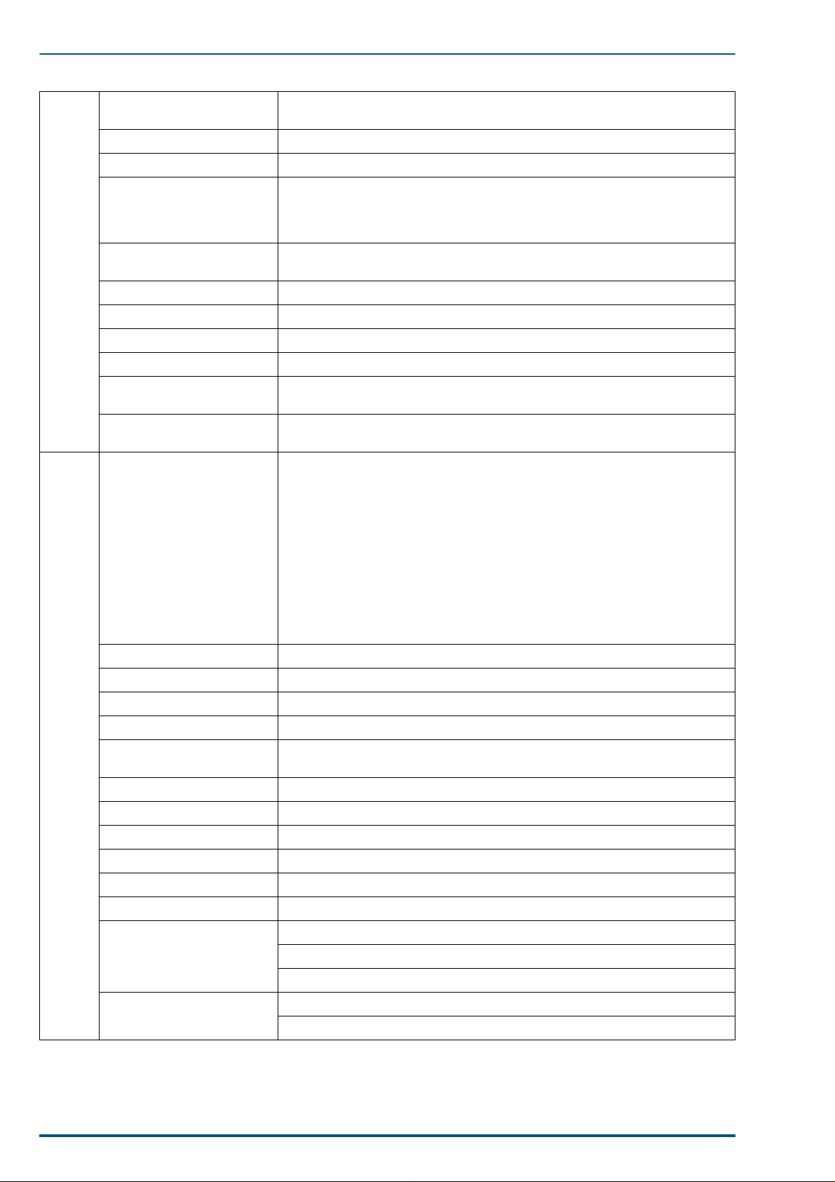
Margins and Print Area
When the printer places an image on media, the image (print area) is a bit smaller than the media size.
Page margins adjustment m ay be needed in an application software to m atch the print area.
The following table lists the page sizes, the maximum print areas, and the margins for the media sizes supported in KPDL emulation, 600dpi.
Media
cm/inch Points Horizontal Vertical
A4 21.0 × 29.7 595 × 842 112 120 4736 × 6784
B5 18.2 × 25.7 516 × 729 174 97 3950 × 5875
ISO B5 17.6 × 25.0 499 × 708 99 102 3958 × 5700
Legal 8.5 × 14 inches 612 × 1008 86 136 4928 × 8128
Letter 8.5 × 11 inches 612 × 792 86 132 4928 × 6336
Executive 7.25 × 10.5 inches 522 × 756 100 100 4150 × 6100
Page Size Edge limitis (A) (dot)
B
Horizontal
edge limit
Printable area
Direction of paper
feeding
Printable area (B) (dot)
A
Vertical edge limit
RAM and printer capabilities
The printer features 16 Mbytes of base RAM and a 32-Mbyte SIMM fit in the one of th e three connectors
that accept 4, 8, 16 and 32-Mbyte RAM SIMMs. With additional RAM memory the printer’s capabilities
increase as follows:
4
Page 5

1. Introduction
When using the Printer Driver and Utilities
Total Memory Selectable Print Quality Mode Printable without Memory Overflow
48 MB (Stan dard)
56 MB (8MB added)
72 MB (24MB added) Letter, A4, Legal
* Documents can be printed on Legal size paper when the print style is set to Color Graphics provided the data size of
the documents is small.
Fast (300 dpi) Letter, A4, Legal
Standard (600 dpi) Letter, A4*
Letter, A4*
High Quality (1200 dpi)
1.2 Options, Accessories and Supplies
Item Description
PF-81
PF-81D
HB-7SNMP
EcoLAN 2000E
TD-81K
TD-81C
TD-81M
TD-81Y
Paper Feeder
Paper Feeder/Duplex Unit
Network Card for Ethernet
Toner developer: Black
Toner developer: Cyan
Toner developer: Magenta
Toner developer: Yellow
FK-81
IU-81
TR-81
OS-81
SA-80
HD-2C
CP-81
MC-81
Fuser
Imaging unit
Transfer unit
Oil Supply Roll
Serial Adapter
HDD unit (2GB)
Cleaning pad for the fuser
Main charger
5
Page 6

FS-5900C Service Manual
1.3 Control Panel Overview
The printer has the following displays and keys. Simple explanation the displays follows. For a full information on using them, refer to the printer’s User’s Manual (also on the CD-ROM).
1.3.1 Message Display
The message display displays the printer’s operational mode. Messages which are displayed and their
meanings are as follows:
Message Meaning
Self test
Please wait
Ready
Processing
Waiting
FormFeed TimeOut
Interface Indicator
The interface indicator indicates the interface over which data is currently being received or was last
received. The current interface is indicated by one of the following messages:
The printer is self-testing after power-up and is not ready to print. This message appears only
at power-up.
The printer is warming up and is not ready to print.
The printer is ready to print.
The printer is processing print data or in the middle of printing.
The last page remains unprinted. The printer waits awhile and eventually generates a form
feed allowing the last page to be printed. (The length of time depends on the form feed timeout
setting.) The printing will begin immediately when the
card is being used this can indicate the printer is waiting for data to be written.
An automatic form feed has been generated.
Form Feed
key is pressed. If a memory
Display Description
PAR
SER
OPT
Note:
The display will blink while the printer is receiving data and continue blinking until the interface is
Parallel interface
Serial interface
Optional interface (if a network interface card is installed)
released, even after data transmission is finished.
6
Page 7

1. Introduction
Resolution Indicator
This shows the current printing resolution in either 1200 or 600 dpi (dot-per-inch).
Paper Size Indicator
This indicator indicates the paper size of the cassette currently selected. The following abbreviations are
used to indicate the paper sizes:
Indicator Paper Size
A4
EX
B5
LT
LG
b5
* These paper sizes can only be fed from the MP tray.
ISO A4 (21 × 29.7 cm)
Executive (7-¼ × 10-½ inches)*
JIS B5 (18.2 × 25.7 cm)*
Letter (8-½ × 11 inches)
Legal (8-½ × 14 inches)
ISO B5 (17.6 × 25.0 cm)*
Copy Indicator
This indicator indicates the number of copies to print from 001 to 999. This number is reduced as printing
proceeds.
7
Page 8
FS-5900C Service Manual
1.4 Rear Panel
1.4.1 Connectors
The rear panel is equipped with the following interface connectors:
• Parallel (high density connector)
• Serial (8-pin mini DIN-type connector)
A converter cable that allows the serial connector to a DSub connector is opt ionally available by the model
number SA-80.
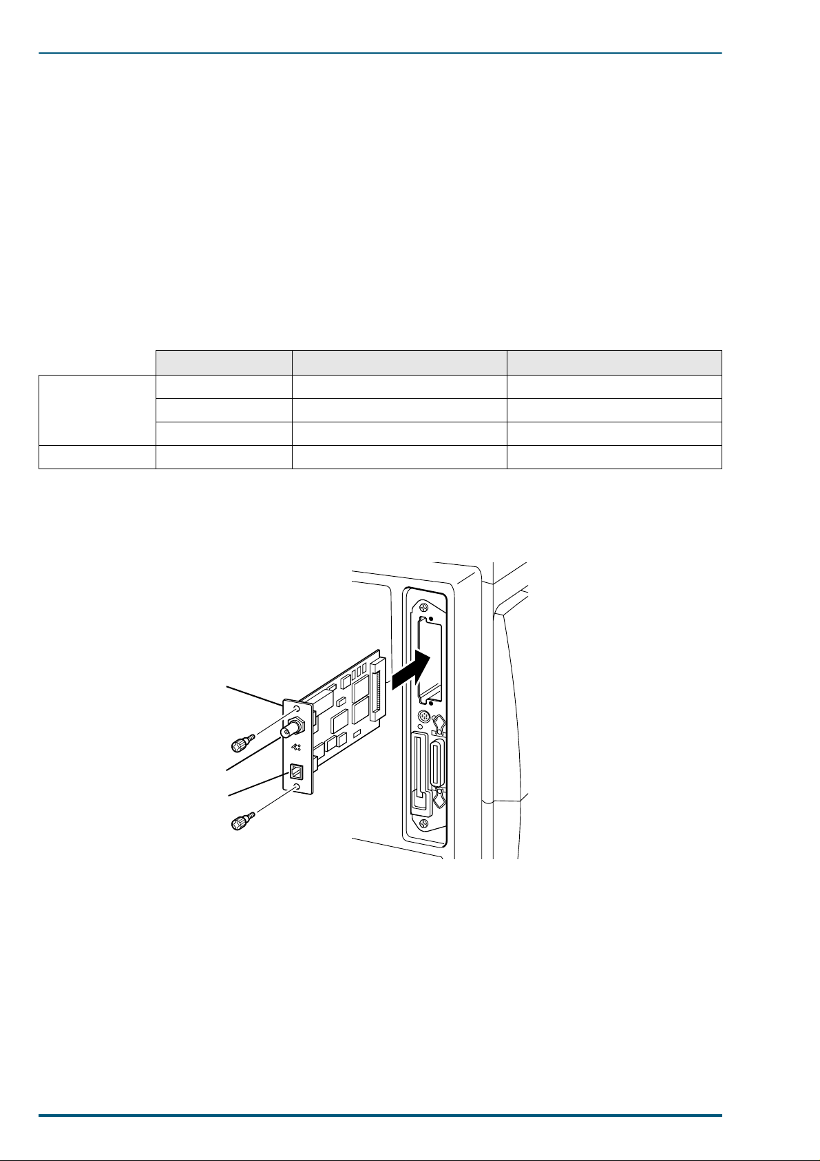
1.4.2 Network card
The network interface card is available in either Ethernet or TokenRing protocol as follows.
See your nearest dealer of the manufacturer for availability.
Manufacturer Model Applicable country
HBM HB-7SNMP Available in UK and France
Ethernet
Token Ring SEH IC69-Token-KYO2 All countries
Two LEDs on the face of the optional network card verify LAN connection and network activity.
DPI EcoLAN 2000E Available in USA and Japan
SEH IC59-ETHER-KYO2 Other countries
Installing the Network Card
Example:
HB-7SNMP EcoLAN 2000E
10BASE2
10BASE-T
8
Page 9
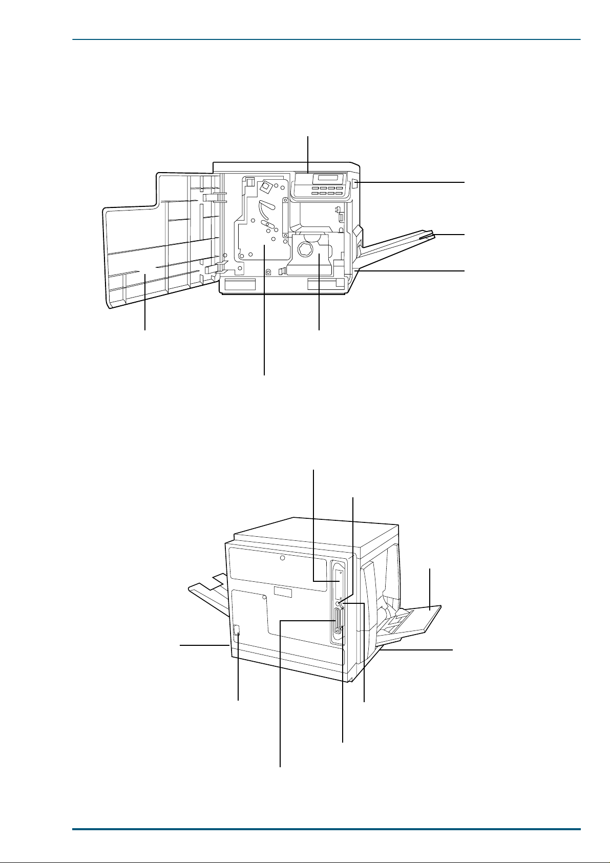
1.5 Parts Identification
1.5.1 Front side view
1. Introduction
Control panel
Right side cover
Output tray
Media cassette
Front cover
1.5.2 Rear side view
Fuser
Imaging unit
Network interface card slot
Serial interface connector
Multi-purpose (MP) tray
Power switch
AC inlet
Left side cover
[Media thickness switch*]
* Accessible by opening the
left side cover
Harddisk access
indicator
Parallel interface co nnect or
Memory card connector
9
Page 10

FS-5900C Service Manual
1.6 Component Layout
10
Page 11
1.7 Electrical Components
Toner Cartridge
Drive Unit
Toner
Cartridge
Motor
Power
Supply
Unit
1. Introduction
Polygon Motor
Driver Board
Ozone Fan
High Voltage
Board
Main Control Board
Engine
Control
Board
Fuser/Toner
Cartridge Fan
Cleaning Board
Paper Feed Motor
Main Motor
Temperature/
Humidity
Sensor Board
Interconnect
Board
Lower Door Open
Sensor
11
Page 12

FS-5900C Service Manual
1.8 Switches/Sensors Identification
12
 Loading...