

Page 1
Laser printer
SERVICE
MANUAL
Published in Oct. ’01
Revision 1.2
Page 2

Revision history
Version Replaced pages RemarksDate
1.0
1.1
1.2
25-Oct-2001
20-Mar-2002
1-Apr-2002
1-4, 1-5, 3-20
1-10, 4-30
Page 3

Safety precautions
This booklet provides safety warnings and precautions for our service personnel to ensure the safety of
their customers, their machines as well as themselves during maintenance activities. Service personnel
are advised to read this booklet carefully to familiarize themselves with the warnings and precautions
described here before engaging in maintenance activities.
Page 4
Safety warnings and precautions
Various symbols are used to protect our service personnel and customers from physical danger and
to prevent damage to their property. These symbols are described below:
DANGER: High risk of serious bodily injury or death may result from insufficient attention to or incorrect
compliance with warning messages using this symbol.
WARNING:Serious bodily injury or death may result from insufficient attention to or incorrect compliance
with warning messages using this symbol.
CAUTION:Bodily injury or damage to property may result from insufficient attention to or incorrect
compliance with warning messages using this symbol.
Symbols
The triangle ( ) symbol indicates a warning including danger and caution. The specific point
of attention is shown inside the symbol.
General warning.
Warning of risk of electric shock.
Warning of high temperature.
indicates a prohibited action. The specific prohibition is shown inside the symbol.
General prohibited action.
Disassembly prohibited.
indicates that action is required. The specific action required is shown inside the symbol.
General action required.
Remove the power plug from the wall outlet.
Always ground the printer.
Page 5
1. Installation Precautions
WARNING
• Do not use a power supply with a voltage other than that specified. Avoid multiple connections to
one outlet: they may cause fire or electric shock. When using an extension cable, always check
that it is adequate for the rated current. ............................................................................................
• Connect the ground wire to a suitable grounding point. Not grounding the printer may cause fire or
electric shock. Connecting the earth wire to an object not approved for the purpose may cause
explosion or electric shock. Never connect the ground cable to any of the following: gas pipes,
lightning rods, ground cables for telephone lines and water pipes or faucets not approved by the
proper authorities. .............................................................................................................................
CAUTION:
• Do not place the printer on an infirm or angled surface: the printer may tip over, causing injury. ....
• Do not install the printer in a humid or dusty place. This may cause fire or electric shock. ..............
• Do not install the printer near a radiator, heater, other heat source or near flammable material.
This may cause fire...........................................................................................................................
• Allow sufficient space around the printer to allow the ventilation grills to keep the machine as cool
as possible. Insufficient ventilation may cause heat buildup and poor copying performance...........
• Always handle the machine by the correct locations when moving it. ..............................................
• Always use anti-toppling and locking devices on printers so equipped. Failure to do this may
cause the printer to move unexpectedly or topple, leading to injury. ................................................
• Avoid inhaling toner or developer excessively. Protect the eyes. If toner or developer is
accidentally ingested, drink a lot of water to dilute it in the stomach and obtain medical attention
immediately. If it gets into the eyes, rinse immediately with copious amounts of water and obtain
medical attention. ..............................................................................................................................
• Advice customers that they must always follow the safety warnings and precautions in the
printer’s instruction handbook. ..........................................................................................................
Page 6
2. Precautions for Maintenance
WARNING
• Always remove the power plug from the wall outlet before starting machine disassembly. .............
• Always follow the procedures for maintenance described in the service manual and other related
brochures. .........................................................................................................................................
• Under no circumstances attempt to bypass or disable safety features including safety
mechanisms and protective circuits. .................................................................................................
• Always use parts having the correct specifications...........................................................................
• Always use the thermostat or thermal fuse specified in the service manual or other related
brochure when replacing them. Using a piece of wire, for example, could lead to fire or other
serious accident. ...............................................................................................................................
• When the service manual or other serious brochure specifies a distance or gap for installation of a
part, always use the correct scale and measure carefully. ...............................................................
• Always check that the printer is correctly connected to an outlet with a ground connection. ...........
• Check that the power cable covering is free of damage. Check that the power plug is dust-free. If
it is dirty, clean it to remove the risk of fire or electric shock. ............................................................
• Never attempt to disassemble the optical unit in machines using lasers. Leaking laser light may
damage eyesight...............................................................................................................................
• Handle the charger sections with care. They are charged to high potentials and may cause
electric shock if handled improperly. .................................................................................................
CAUTION
• Wear safe clothing. If wearing loose clothing or accessories such as ties, make sure they are
safely secured so they will not be caught in rotating sections. .........................................................
• Use utmost caution when working on a powered machine. Keep away from chains and belts........
• Handle the fixing section with care to avoid burns as it can be extremely hot..................................
• Check that the fixing unit thermistor, heat and press rollers are clean. Dirt on them can cause
abnormally high temperatures. .........................................................................................................
• Do not remove the ozone filter, if any, from the printer except for routine replacement. ..................
Page 7
• Do not pull on the AC power cord or connector wires on high-voltage components when removing
them; always hold the plug itself. ......................................................................................................
• Do not route the power cable where it may be stood on or trapped. If necessary, protect it with a
cable cover or other appropriate item. ..............................................................................................
• Treat the ends of the wire carefully when installing a new charger wire to avoid electric leaks. ......
• Remove toner completely from electronic components. ...................................................................
• Run wire harnesses carefully so that wires will not be trapped or damaged. ...................................
• After maintenance, always check that all the parts, screws, connectors and wires that were
removed, have been refitted correctly. Special attention should be paid to any forgotten
connector, trapped wire and missing screws. ..................................................................................
• Check that all the caution labels that should be present on the machine according to the
instruction handbook are clean and not peeling. Replace with new ones if necessary. ...................
• Handle greases and solvents with care by following the instructions below:....................................
· Use only a small amount of solvent at a time, being careful not to spill. Wipe spills off completely.
· Ventilate the room well while using grease or solvents.
· Allow applied solvents to evaporate completely before refitting the covers or turning the main
switch on.
· Always wash hands afterwards.
• Never dispose of toner or toner bottles in fire. Toner may cause sparks when exposed directly to
fire in a furnace, etc. .........................................................................................................................
• Should smoke be seen coming from the printer, remove the power plug from the wall outlet
immediately.......................................................................................................................................
3. Miscellaneous
WARNING
• Never attempt to heat the drum or expose it to any organic solvents such as alcohol, other than
the specified refiner; it may generate toxic gas.................................................................................
Page 8

Contents
Chapter 1
1-1 Printer specifications .......................................................................................................................................1-3
1-2 Names of parts ................................................................................................................................................1-9
1-3 Safety information..........................................................................................................................................1-10
1-4 Environmental requirements..........................................................................................................................1-13
1-5 About the toner container ..............................................................................................................................1-17
Chapter 2
2-1 Unpacking........................................................................................................................................................2-3
2-2 Installing the printer .........................................................................................................................................2-5
2-3 Using the operator panel ...............................................................................................................................2-17
Chapter 3
3-1 Maintenance/Adjustments ...............................................................................................................................3-3
Chapter 4
4-1 Electrophotographic system ............................................................................................................................4-3
4-2 Paper feeding system....................................................................................................................................4-18
4-3 Electrical control system................................................................................................................................4-23
Chapter 5
5-1 General instructions.........................................................................................................................................5-3
5-2 Disassembly ....................................................................................................................................................5-4
Chapter 6
6-1 Troubleshooting...............................................................................................................................................6-4
Appendix A
Timing charts ........................................................................................................................................................ A-4
Wiring diagram...................................................................................................................................................... A-9
Appendix B
Status page........................................................................................................................................................... B-3
Appendix C
Parallel interface ................................................................................................................................................... C-3
Serial interface...................................................................................................................................................... C-6
1-1-1
Page 9

Chapter 1
Product Information
Page 10

Chapter 1 Contents
1-1 Printer specifications ...................................................................................................................... 1-3
1-1-1 Specifications ............................................................................................................................ 1-3
(1) Engine ....................................................................................................................................... 1-3
(2) Controller ................................................................................................................................... 1-4
(3) Weight and dimensions ............................................................................................................. 1-4
(4) Power requirements .................................................................................................................. 1-5
(5) Environmental requirements...................................................................................................... 1-5
1-1-2 Available option memory/device................................................................................................ 1-6
(1) Expansion memory (DIMM)....................................................................................................... 1-6
(2) Memory card (CompactFlash) ................................................................................................... 1-7
(3) Hard disk (Microdrive) ............................................................................................................... 1-8
1-2 Names of parts ................................................................................................................................. 1-9
1-2-1 Names of parts .......................................................................................................................... 1-9
1-3 Safety information ......................................................................................................................... 1-10
1-3-1 Safety information.................................................................................................................... 1-10
(1) Laser caution label on the scanner unit................................................................................... 1-10
(2) Ozone concentration ................................................................................................................1-11
(3) ISO 7779 ..................................................................................................................................1-11
(4) CE marking directive ................................................................................................................1-11
(5) Declaration of conformity (Australia) ....................................................................................... 1-12
1-4 Environmental requirements ........................................................................................................ 1-13
1-4-1 Environmental conditions ........................................................................................................ 1-13
(1) Clearance ................................................................................................................................ 1-14
(2) Places to avoid ........................................................................................................................ 1-15
(3) Note on power ......................................................................................................................... 1-15
(4) Removing the printer ............................................................................................................... 1-16
1-5 About the toner container ............................................................................................................. 1-17
1-5-1 Toner container........................................................................................................................ 1-17
(1) Toner container handling ......................................................................................................... 1-17
(2) Toner container storage........................................................................................................... 1-18
Page 11

1-1 Printer specifications
1-1-1 Specifications
(1) Engine
Item Description
Print method
Print speed (when printing
multiple pages)
Resolution
Smoothing
First print (A4 or letter, 23 °C),
depends on input data
Warm-up time Power on:
(23 °C ) Sleeping:
Maximum duty cycle (A4)
Machine life expectancy
Development
Laser
Main charger
Electrophotography laser scan
18 pages/min. (A4)
Fine 1200 mode
Fast 1200 mode with KIR
600 dpi with KIR
300 dpi with KIR
KIR (Kyocera Image Refinement)
Approximately 19 seconds or less
16 seconds or less
9 seconds or less
65,000 pages/month (Average: 4,000 pages/month)
300,000 pages of printing or 5 years
(expandable to 900,000 pages of printing using MK kits)
Mono component dry developer
Visible laser (Semiconductor laser)
Scorotron plus charging
Transferring
Separation
Drum cleaning
Drum discharging
Fuser
Paper
Capacity of paper feed source
(80 g/m2 [0.11 mm thickness])
Capacity of output trays
(80 g/m2 [0.11 mm thickness])
Negative charger roller
Curvature separation
Blade
Eraser lamp (LED array)
Heat roller and press roller
Plain paper
Cassette: 500 sheets,
MP tray: 100 sheets
Face-up: 250 sheets [Option face-up tray PT-4]
100 sheets [Option face-up tray PT-60]
Face-down: 250 sheets
FS-1800+
1-3
Page 12

(2) Controller
Item Description
CPU
PowerPC405GF/200MHz
System ROM
Font ROM
Main (Video) RAM
Maximum:
Slot:
DIMM size:
Memory card (Optional)
Hard disk (Optional)
Host interface Parallel:
Serial:
KUIO-LV [3.3 V]:
Page description language
Standard emulation modes
(3) Weight and dimensions
4 MB Mask (or Flash) DIMM
2 MB
8 MB
264 MB (Including main RAM)
2 DIMM slots
16 MB/ 32 MB/ 64 MB/ 128 MB
CompactFlash
Microdrive (340 MB/ 512 MB/ 1 GB )
High-speed, bidirectional (IEEE1284)
RS-232C, Maximum speed: 115.2 Kbps
Network interface card IB-21 (Optional): 10/100 Base-TX
Prescribe
PCL6, Diablo 630, IBM proprinter X24E, Epson LQ850, Line
printer, KPDL
Item Description
Main unit Width:
(excluding Height:
protrusions) Depth:
Weight:
FS-1800+
34.5 cm (13-9/16 inches)
30.0 cm (11-13/16 inches)
39.0 cm (18-1/4 inches)
13 Kg (28-5/8 lb.)
1-4
Page 13

(4) Power requirements
Item Description
Voltage/current
220 - 240 V AC ±10 %, 50/60 Hz ±2 %/3.6 A
120 V AC ±10 %, 60 Hz ±2 %/7.2 A
Watts Maximum:
Standby (Ready):
Sleeping:
961 W
23 W
14 W
(5) Environmental requirements
Item Description
Operating temperature and
10 to 32.5 °C (50 to 90.5 °F), 20 to 80 %RH
humidity
Maximum altitude
Noise emission (Excluding
peaks, measured at 1 m from
2,000 m (6,500 feet)
Maximum: 53 dB(A)
Standby: 35 dB(A)
printer, as per ISO7779)
1-5
FS-1800+
Page 14

1-1-2 Available option memory/device (1) Expansion memory (DIMM)
The following option memory DIMMs are available for use with the printer. For more informations
about DIMM, refer to Section 2-2-3 Expanding the memory (DIMM) on page 2-10.
NOTE Availability of the following memory DIMMs, manufacturers, and
specifications may change without notice. No responsibility is assumed by
Kyocera Mita with respect to loss or damage caused by the use of these
DIMMs. Only the following DIMMs are certified the for use with the printer.
Manufacturer Capacity Model
Melco Inc. 16 MB PM-HP-16M-KC
32 MB PM-HP-32M-KC
64 MB PM-HP-64M-KC
128 MB PM-HP-128M-KC
FS-1800+
1-6
Page 15

(2) Memory card (CompactFlash)
The following memory cards are available for use with the printer. Do not insert or remove a
memory card (CompactFlash) while power is on. If the memory card is removed while the printer
is on, damage could result in the printer’s electronics or the memory card. Refer to Section Installing
the option memory card (CompactFlash) on page 2-15.
NOTE Availability of the following memory cards (CompactFlash), manufacturers,
and specifications may change without notice. No responsibility is assumed by
kyocera Mita with respect to loss or damage caused by the use of these
memory card.
Manufacturer Capacity Model
SanDisk 8 MB SDCFBS-8-101
16 MB SDCFBS-16-101
24 MB SDCFBS-24-101
32 MB SDCFBS-32-101
48 MB SDCFBS-48-101
64 MB SDCFBS-64-101
96 MB SDCFBS-96-101
Viking 4 MB CF4M
8 MB CF8M
12 MB CF12M
16 MB CF16M
24 MB CF24M
32 MB CF32M
48 MB CF48M
64 MB CF64M
80 MB CF80M
Kingston 8 MB CF/8
16 MB CF/16
24 MB CF/24
32 MB CF/32
48 MB CF/48
64 MB CF/64
96 MB CF/96
1-7
FS-1800+
Page 16

Manufacturer Capacity Model
DelkinDevices Inc. 8 MB DDCFFLS2-008
16 MB DDCFFLS2-016
24 MB DDCFFLS2-024
32 MB DDCFFLS2-032
48 MB DDCFFLS2-048
64 MB DDCFFLS2-064
96 MB DDCFFLS2-096
HITACHI 8 MB HB286008C4
16 MB HB286016C4
32 MB HB289032C4
48 MB HB289048C4
64 MB HB288064C5
Transcend 4 MB TS4MFLASHCP
8 MB TS8MFLASHCP
16 MB TS16MFLASHCP
32 MB TS32MFLASHCP
SST 8 MB SST48CF008
16 MB SST48CF016
24 MB SST48CF024
32 MB SST48CF032
48 MB SST48CF048
64 MB SST48CF064
96 MB SST48CF096
LEXAR Media 16 MB -
32 MB 48 MB 64 MB 80 MB -
(3) Hard disk (Microdrive)
The following hard disk is available for the printer:
IBM Microdrive 340 MB/512 MB/1 GB
FS-1800+
1-8
Page 17
1-2 Names of parts
1-2-1 Names of parts
0
9
!
&
7
8
@
2
6
1
3
4
5
#
¤
⁄
)
‹
1 T op cover
2 T oner container
3 Operator panel
4 Paper gauge
5 Paper cassette
6 Paper size window
7 Power switch
8 Paper size dial
9 Waste toner bottle
0 Side cover
*
(
! Charger Cleaning knob
@ Paper stopper
# Face-down output tray
$ Memory card slot
% Paper feed unit
^
Paper feed unit release lever
& MP tray
Figure 1-2-1 Name of parts
$
%
^
* Rear cover
( AC inlet
) Parallel interface connector
⁄ Serial interface connector
¤ Option unit connector
‹ Network interface card (option)
1-9
FS-1800+
Page 18
1-3 Safety information
1-3-1 Safety information
(1) Laser caution label on the scanner unit
The laser scanner unit inside the printer has the following label affixed on its top. Observe the laser
radiation warning and figures when handling the laser scanner unit.
WARNING Use of controls or adjustments or performance of procedures other than those
specified herein may result in hazardous radiation exposure.
This label is affixed atop of the laser scanner unit inside the printer .
Label on the scanner unit (Inside the printer)
Label on the right cover rear side
European countries U.S.A/Canada
Label on the fuser unit
FS-1800+
Figure 1-3-1 Caution labels
1-10
Page 19

(2) Ozone concentration
The printers generate ozone gas (O3) which may concentrate in the place of installation and cause
an unpleasant smell. To minimize concentration of ozone gas to less than 0.1 ppm, we recommend
you not to install the printer in a confined area where ventilation is blocked.
(3) ISO 7779
Maschinenlärminformationsverordnung 3. GSGV, 18.01.1991: Der höchste Schalldruckpegel beträgt
70 dB(A) oder weniger gemäß ISO 7779.
(4) CE marking directive
According to Council Directive 89/336/EEC and 73/23/EEC
Manufacturer's name: Kyocera Corporation, Mie Plant Tamaki Block.
Manufacturer's address: 704-19 Nojino, Tamaki-Cho, Watarai-Gun, Mie-Ken 519-0497, Japan
declares that the product
Product name: Page Printer
Model number: FS-1800+ (as tested with the enhancement optional unit: PF-60, DU-60, and SO-
60)
Conforms to the following product specifications.
EN 55 022:1998 Class B
EN 61 000-3-2:1995
EN 61 000-3-3:1995
EN 55 024:1998
EN 60 950:1992 (+A1+A2+A3+A4+A11)
EN 60 825-1:1994+A11
The manufacturer and its merchandising companies retain the following technical documentation
in anticipation of the inspection that may be conducted by the authorities concerned.
User's instruction that conforms to the applicable specifications
Technical drawings
Descriptions of the procedures that guarantee the conformity
Other technical information
1-11
FS-1800+
Page 20

(5) Declaration of conformity (Australia)
Manufacturer's name: Kyocera Corporation, Printer Division
Manufacturer's address: 2-14-9 Tamagawadai, Setagaya Ward, Tokyo 158-8610, Japan
declares that the product
Product name: Page printer
Model number: FS-1800+ (as tested with the enhancement optional units: PF-60, DU-60, and SO-
60)
Description of device: This page printer model FS-1800+ is the 18 ppm; A4 size and utilized plane
paper; laser; dry toner etc. The printer can be equipped with several enhancement optional units as
a paper feeder as PF-60, a duplexer as DU-60, a sorter as SO-60 etc.
Conforms to the following product specifications.
AS/NZS 3548: 1995 (EN 55 022:1994 Class B)
IEC60950 (EN 60 950:1992+A1+A2+A3+A4+A11)
IEC60825-1 (EN 60 825-1:1994+A11)
The manufacturer and its merchandising companies retain the following technical documentation
in anticipation of the inspection that may be conducted by the authorities concerned.
User's instruction that conforms to the applicable specifications
Technical drawings
Descriptions of the procedures that guarantee the conformity
Other technical information
Kyocera Mita Australia Pty., Ltd.
6-10 Talavera Road, North Ryde, NSW, 2113, Australia
Phone: +61 2-9888-9999
Fax: +61 2-9888-9588
FS-1800+
1-12
Page 21

1-4 Environmental requirements
1-4-1 Environmental conditions
The Environmental requirements section on page 1-5 should be observed to ensure the optimum
operation of the printer . The use of the printer in a location which does not satisfy the requirements
may result in troubles and risk shortening its service life.
The printer will work best if it is installed in a location that is:
• Level and well supported (Place the printer on a table or desk.)
• Not exposed to sunlight or other bright light (not next to an uncurtained window). Do not place
the printer on an unstable cart, stand or table.
• Near an AC wall outlet, preferably one that can be used for the printer alone. The outlet should
have a ground slot, or an adapter should be used. If you use an extension cord, the total length of
the power cord plus extension cord should be 17 feet or 5 meters or less.
• Well ventilated, not too hot or cold, and not too damp or dry (See section Environmental
requirements on page 1-5). If you install the printer where the temperature or humidity is outside
the requirements in section Environmental requirements in chapter 1, the best print quality may
not be expected and there will be an increased chance of paper jams.
• Provide a sufficient clearances around the printer to ensure ventilation and ease of access. (See
section Clearance on next page).
1-13
FS-1800+
Page 22
(1) Clearance
Allow the necessary minimum clearance on all sides of the printer as below.
5
4
1
3
2
Figure 1-4-1 Clearances
Ref. Clearance Dimensions [Minimum]
1 Left 30 cm (11-13/16 inches)
2 Front 60 cm (23-5/8 inches)
3 Right 25 cm (9-7/8 inches)
4 Back 20 cm (7-7/8 inches)
5 Head room 30 cm (11-13/16 inches)
FS-1800+
1-14
Page 23

(2) Places to avoid
Avoid installing the printer in locations exposed to:
• Direct drafts of hot or cold air.
• Direct drafts of outside air. (Avoid locations next to outside doors.)
• Sudden temperature or humidity changes.
• Any source of high heat, such as a radiator or stove.
• Excessive dust. Dust and smoke may cause contamination on the laser scanner window , causing
print quality problem.
• Vibration.
• Ammonia fumes or other harmful fumes. (In case of fumigating the room or saturate it with
insecticide, remove the printer first.)
• Avoid greenhouse-like rooms. (Because of sunlight and humidity.)
• Avoid enclosed spaces that block ventilation.
• Avoid sites more than 6,500 feet or 2,000 meters above sea level.
(3) Note on power
Use only the power source voltage conforming to the printer’s rated power voltage. Do not use
other power sources.
• Disconnect the printer from the power source before attempting removal or replacement of an
electrical component or a printed-circuit board.
• The printer should not be connected to a power source until the instruction is given to do so
when performing tests described in this manual.
• In connecting the printer power, exercise an extreme care in handling the power supply or any
other electric parts which may give an electric shock.
• Before performing maintenance or repair, power from both the power source and the associated
peripheral devices (computer, sorter, etc.) should be disconnected, unless otherwise specified.
• To avoid possible electrical shock, extreme caution must be exercised in handling the power
cord and any other electrical part.
• An easily accessible socket outlet must be provided near the equipment.
WARNING As the disconnect device is not incorporated in the printer’s AC primary
circuit, an easily accessible socket outlet must be provided near the equipment.
1-15
FS-1800+
Page 24

(4) Removing the printer
Observe the following precautions in removal and transportation of the printer.
• Be sure to repack the printer in its original carton.
• Do not leave the printer, toner container , process unit and other printer modules inside a vehicle
if the outdoor temperature is more than 25 °C. As unexpectedly high temperature may develop
inside when a vehicle is parked for a long period of time, the drum, toner container, process unit
and the supplies should be removed from the vehicle. The vehicle during transportation should
be parked in the shade or with the window open to allow minimum air circulation or the adequate
air conditioning should be made.
• Should the printer be left in a vehicle, it may not be exposed to the temperature change of more
than 7 °C within 30 minutes.
• Before removing the printer to a warm place, wrap it in a blanket, etc., before crating it. Allow
approximately two to three hours after having moved after uncrated. Failure to observe the
above may result in moisture condensation which will affect the performance of the printer.
FS-1800+
1-16
Page 25
1-5 About the toner container
1-5-1 Toner container
The printer should use a Kyocera TK-60/TK-60E toner kit. To ensure the high print quality and
long service life, the following handling precautions should apply:
CAUTION As the Ecosys printers are designed to ensure the optimum print quality when
used with Kyocera’s proprietary toner, Kyocera do not recommend to use any
refilled toner containers that may be available commercially. This is because
Kyocera have no means of control over how such refilled toner could affect the
print quality and the reliability of the printer.
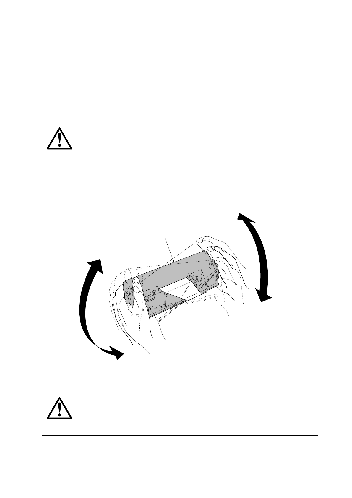
(1) Toner container handling
To loosen and mix the toner inside before use, with the label side down, thoroughly shake the toner
container 1 (in the direction of the arrows) ten times or more.
1
Figure 1-5-1 Toner container handling
CAUTION The toner container is not designed for disassembly or refilling. Do not attempt
to disassemble or refill the toner container.
1-17
FS-1800+
Page 26

(2) Toner container storage
The toner contained in the container is susceptible to temperature and humidity. To ensure the high
print quality, store the toner container in a place that satisfies the following environmental conditions:
Temperature: −20 to 40 °C (−4 to 104 °F)
Humidity: 15 to 90 % RH
NOTE If the toner container is removed from the printer’s developer, put it in a
protective bag and keep it in a dark place.
CAUTION If the printer is shipped for return, etc., do not ship it with the toner container
installed. Remove the toner container from the developer and put in a plastic
bag and seal the plastic bag. Otherwise, toner may leak and contamination may
result in the printer.
FS-1800+
1-18
Page 27

Chapter 2
Installation/Operation
Page 28

Chapter 2 Contents
2-1 Unpacking......................................................................................................................................... 2-3
2-1-1 Unpacking and inspection ......................................................................................................... 2-3
2-2 Installing the printer ........................................................................................................................ 2-5
2-2-1 Installing the toner container ..................................................................................................... 2-5
Removing the toner container......................................................................................................... 2-7
2-2-2 Installing the waste toner bottle ................................................................................................. 2-8
Removing the waste toner bottle .................................................................................................... 2-9
2-2-3 Expanding the memory (DIMM)............................................................................................... 2-10
(1) Minimum memory requirements .............................................................................................. 2-10
(2) DIMM specifications ................................................................................................................ 2-10
(3) Notes on handling DIMM ..........................................................................................................2-11
(4) Installing the DIMM.................................................................................................................. 2-12
(5) Testing the expansion memory................................................................................................ 2-13
(6) Installing the option hard disk (Microdrive) .............................................................................. 2-14
(7) Installing the option memory card (CompactFlash) ................................................................. 2-15
(8) Installing the option network interface card ............................................................................. 2-16
2-3 Using the operator panel............................................................................................................... 2-17
2-3-1 Operator panel......................................................................................................................... 2-17
(1) Indicators and keys.................................................................................................................. 2-17
(2) Interface indicator .................................................................................................................... 2-19
(3) Paper size indicator ................................................................................................................. 2-19
(4) Paper type Indicator ................................................................................................................ 2-20
(5) Message display...................................................................................................................... 2-21
2-3-2 Menu selection system ............................................................................................................ 2-22
(1) Menu selection and sequence................................................................................................. 2-22
Page 29
2-1 Unpacking
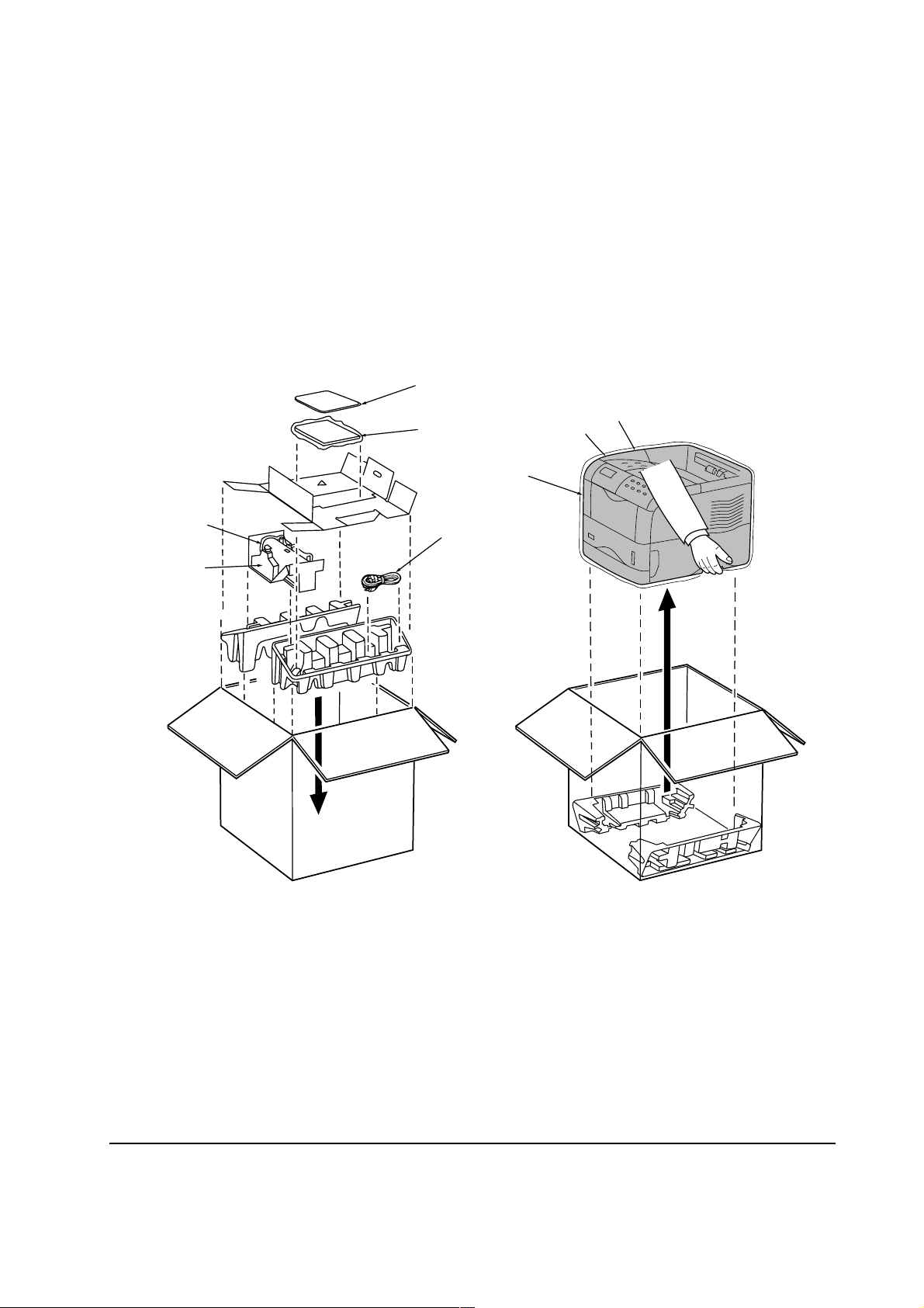
2-1-1 Unpacking and inspection
The printer package should contain the items as shown in the figure below. After unpacking, remove
the printer and all the accessories from the package.
For unpacking, place the box containing the printer on a flat, stable surface. Remove the manuals,
toner kit, and other items located on top of the spacer. Then remove the spacer. Carefully remove
the printer. Obtain help from other persons if necessary.
7
56
1
2
3
1 Printer
4
Figure 2-1-1 Unpacking
5 Installation manual
2 Toner container
3 Waste toner bottle
4 Power cord
6 Kyocera digital library CD-ROM
7 Plastic bag
FS-1800+
2-3
Page 30
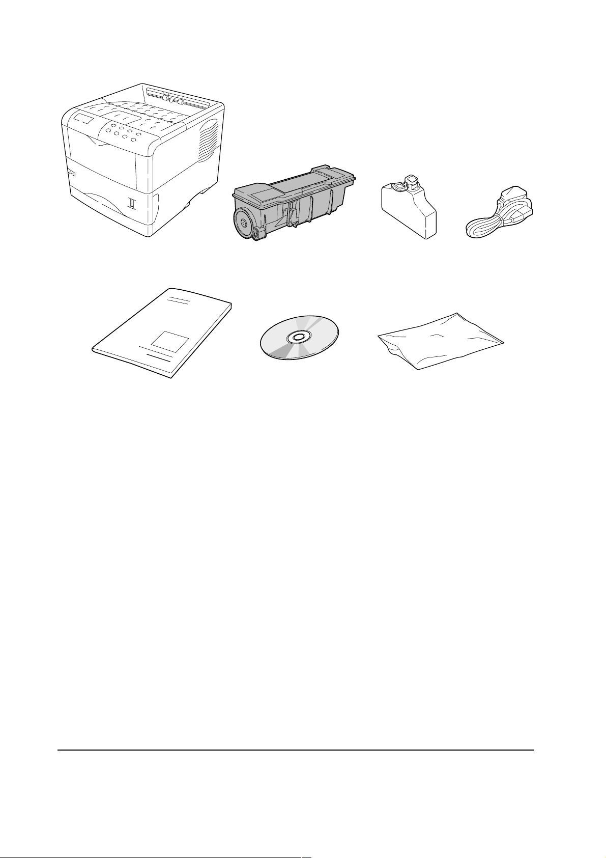
1
5
1 Printer
2 Toner container
2
6
3
4
7
5 Installation manual
6 Kyocera digital library CD-ROM
3 Waste toner bottle
7 Plastic bag
4 Power cord
Figure 2-1-2 List of shipped components
FS-1800+
2-4
Page 31

2-2 Installing the printer
Installing the printer requires several steps. Proceed as follows in sequence.
2-2-1 Installing the toner container
1. Open the top cover all the way.
2. Take toner container 1 from the bag. With the label side down and pivoting on the middle of
the container, thoroughly shake the toner container (in the direction of the arrows) ten times or
more to loosen and mix the toner inside.
1
Figure 2-2-1 Shake the toner container
2-5
FS-1800+
Page 32

3. Carefully remove the protective seal 2.
Figure 2-2-2 Removing the protective seal
2
4. Install the toner container 2 into the printer.
5. Push firmly on the top of the toner container 2 at the positions marked [PUSH HERE].
FS-1800+
Figure 2-2-3 Installing the toner container
2-6
Page 33

Removing the toner container
To remove the toner container, pull the lock lever (green colored) 1 and gently lift the toner
container.
NOTE Do not remove the toner container unless you need to do so for servicing, etc.
1
Figure- 2-2-4 Removing the toner container
2-7
FS-1800+
Page 34

2-2-2 Installing the waste toner bottle
The waste toner bottle must be installed in the printer. It must be properly fitted inside the left side
cover as explained below.
1. Open the cap 1 of the waste toner bottle 2.
2. Open the side cover 3 and install the waste toner bottle 2 so that it is properly seated in the
area under the drum unit.
3. Close the side cover 3.
1
3
3
2
2
FS-1800+
Figure 2-2-5 Installing the waste toner bottle
2-8
Page 35

Removing the waste toner bottle
To remove the waste toner bottle 1, while holding the waste toner bottle 1, press the lock lever
2 aside, then gently remove the waste toner bottle 1 sideways.
NOTE Do not remove the waste toner bottle unless you need to do so for service, etc.
2
1
Figure 2-2-6 Removing the waste toner bottle
2-9
FS-1800+
Page 36

2-2-3 Expanding the memory (DIMM)
The FS-1800+ comes standard-equipped with 8 MB of main memory . The FS-1800+ can be expanded
up to the maximum of 264 MB (8 MB + 256 MB). Expansion should be done using optional
DIMMs (Dual In-line Memory Module).
(1) Minimum memory requirements
Resolution
Printing environment 300 dpi 600 dpi 1200 dpi
Fast mode Fine mode
PCL6, duplex mode = None 8 MB 8 MB 8 MB 8 MB
PCL6, duplex mode = On 8 MB 8 MB 8 MB 12 MB
KPDL, duplex mode = None 8 MB 8 MB 8 MB 8 MB
KPDL, duplex mode = On 8 MB 8 MB 12 MB 12 MB
PCL6/KPDL resource protection, - 10 MB 10 MB 10 MB
duplex mode = None
PCL6/KPDL resource protection, - 14 MB 14 MB 14 MB
duplex mode = ON
(2) DIMM specifications
Memory size in MB 16, 32, 64, 128 MB
Number of pins 100 pins
Access speed 66 MHz
Parity None
Bus width 32 bits
Item Specification
FS-1800+
2-10
Page 37

(3) Notes on handling DIMM
Before proceeding to install DIMM, to protect the main board and DIMMs, read the following
notes:
NOTE • Before touching a DIMM, touch a water pipe or other large metal object to
discharge yourself of static electricity.
• While doing the work, it is recommended that you wear an antistatic wrist
strap.
• Touch the main board and DIMM only by the edges, not in the middle.
Figure 2-2-7 Handling DIMM
2-11
FS-1800+
Page 38

(4) Installing the DIMM
The main board of the printer is equipped with two sockets for installing extra DIMMs.
CAUTION Be sure that no foreign objects such as metal chips or liquid get inside the
printer during installing DIMMs. Operation of the printer during the presence
of a foreign substance may lead to fire or electric shock.
WARNING Before proceeding installation, turn the printer’s power switch off. Unplug the
printer’s power cable and disconnect the printer from the computer or the
network.
1. Turn the power switch off.
2. Remove the memory card (CompactFlash) that may be inserted in the memory card slot 1 at
the left side of the printer.
3. Remove the main board 2 by removing the two (plated) screws 3.
4. Pull the main board 2 all the way out of the printer.
FS-1800+
2
1
3
3
Figure 2-2-8 Removing the main board
2-12
Page 39

5. Open the clips 4 on both ends of the DIMM socket 5.
6. Insert the DIMM 6 into the DIMM socket 5 so that the notches on the DIMM align with the
corresponding protrusions in the slot.
6
4
4
5
Figure 2-2-9 Inserting the DIMM (1)
7. Close the clips 4 on the DIMM socket 5 to secure the DIMM 6.
6
44
5
Figure 2-2-10 Inserting the DIMM (2)
(5) Testing the expansion memory
To test the expansion memory, turn printer power on and print a status page. If the installation has
been successful, the Available Memory item of the status page will show the expanded memory
size corresponding to the amount of memory added.
FS-1800+
2-13
Page 40

(6) Installing the option hard disk (Microdrive)
The main board of the printer is equipped with a socket for the hard disk (Microdrive). If the hard
disk is installed in the printer, received data can be rasterized and stored on this hard disk. This
enables high-speed printing of multiple copies using an electronic sort function. Also, by using the
quick copy job function or private/stored job function, desired documents can be printed at any
later time. For details of these functions, refer to the printer’s Users Manual.
CAUTION Take precautions that no foreign objects such as metal chips or liquid get inside
the printer during the installation process. Operation of the printer during the
presence of a foreign objects may lead to fire or electric shock.
WARNING Turn the printer’s power switch off. Unplug the printer’s power cable and
disconnect the printer from the computer or the network.
1. Turn the power switch off.
2. Remove the main board 1 from the printer. (See step 2 to 4, on page 2-12.)
3. Install the hard disk 2 to the hard disk slot 3.
3
2
FS-1800+
1
Figure 2-2-11 Installing the option hard disk
2-14
Page 41

(7) Installing the option memory card (CompactFlash)
CAUTION Do not insert or remove a memory card (CompactFlash) while power is on. If
the memory card is removed while the printer is on, damage could result in the
printer’s electronics or the memory card.
1. Turn the power switch off.
2. Insert the memory card 1 in the memory card slot 2 at the right bottom of the printer. Insert it
face up, connector end first. Push it in all the way.
2
1
Figure 2-2-12 Installing the option memory card
2-15
FS-1800+
Page 42

(8) Installing the option network interface card
The main board of the printer is equipped with a network interface card slot (KUIO-LV type, 3.3
V).
CAUTION Be sure that no foreign object such as metal chips or liquid get inside the
printer during the installation process. Operation of the printer during the
presence of a foreign object may lead to fire or electric shock.
WARNING Turn the printer’s power switch off. Unplug the printer’s power cable and
disconnect the printer from the computer.
1. Turn the power switch off.
2. Remove the two screws 1 then remove the option interface card slot cover 2.
3. Insert the network interface card 3 to the option interface card slot 4.
4. Fix the network interface card 3 by two screws 1.
5. Connect the network cable 5 to the network interface card 3.
6. Set the network address from the printer operator panel. (Refer to the printer’s User’s Manual)
2
1
3
5
4
FS-1800+
3
Figure 2-2-13 Installing the option network interface card
2-16
Page 43

2-3 Using the operator panel
This section provides explanation on how to use the printer’s operator panel.
For details on operating the printer, refer to the printer’s User’s Manual.
2-3-1 Operator panel
The printer’s operator panel has the following indicators, keys and message display. Note that
adjustments made using these keys may be overridden by those made from within the application
software.
Message display
$#@
Figure 2-3-1 Operator panel
(1) Indicators and keys
Indicator Condition Description
1 READY indicator
Flashing
Lit
Off
123 4
5
An error has occurred that the user can clear.
The printer is on-line and ready to print.
The printer is off-line. The printers stores but does not
print received data. This is also indicates when printing
9 7 0
6 8 !
2 DATA indicator
3
ATTENTION indicator
Flashing
Lit
Flashing
Lit
Off
is automatically stopped due to the occurrence of an error.
Data transfer between the printer and the computer is
taking place.
Either data is being processed, or data is being written
onto the option CompactFlash or Microdrive.
The printer needs maintenance attention or the printer is
warming up (Please wait).
A problem or an error has occurred that the user can
clear, for example, paper jam.
Operations are normal.
FS-1800+
2-17
Page 44

Key Function
4 GO key
5 CANCEL key
• Switches the printer on-line and off-line.
• Prints and feed out one page.
• Cancels a printing job.
To cancel a print job, proceed as follows:
1. Check the message Processing is displayed in the message
display.
2. Press the CANCEL key.
3. The message Print Cancel? will appear in the message display
and the interface to be canceled will be displayed.
Parallel
Serial
Option (appears only when an [option] network interface card is
installed)
Press the CANCEL key again if you wish to stop the cancellation of
printing.
4. Selecting the interface to cancel using the or key. Then press
the ENTER key. Printing from the interface selected will be stopped.
6 MENU key
7 key
8 key
9 < key
0 > key ( key)
The Cancelling data message appears in the message display
and printing stops after the printer finishes printing the current page.
• Resets numeric values, or cancels a setting procedure.
• Stops the sound alarm that indicates the occurrence of an error.
• Enter menu mode
• When pressed during menu selection, terminates the setting and returns
to the Ready condition.
Lets you access the desired item or enter numeric values. In some of the
control procedures, the < and > keys are used to enter or exit the sub items.
Enables access to the desired item or entering of numeric values. In some
of the control procedures, the < and > keys are used to enter or exit the sub
items.
Used as the < key in the menu selection.
• Used as the > key in the menu selection.
• Displays on-line help messages on the message display when paper jam
occur. When pressed in the Ready condition, displays on-line help
messages.
! ENTER key
FS-1800+
Finalizes numeric values and other selections in menu selection.
2-18
Page 45

(2) Interface indicator
The INTERFACE indicator $ shows which of the printer's interfaces is currently active. It uses
the following abbreviations:
Message Meaning
--- No interface is currently used
PAR Standard bidirectional parallel interface
SER Serial interface (RS-232C)
OPT [Option] network interface card
The PAR , SER , or OPT indicator flashes when the printer is receiving data and remains indicated
for the duration of the interface time-out time.
(3) Paper size indicator
The SIZE indicator # indicates the size of the current paper cassette. Default is Letter size for the
U.S.A. and A4 for European countries. While the printer is Processing data to print, the SIZE
indicator switches to indicate the paper size selected by the application software.
The following abbreviations are used to indicate paper sizes.
Message Paper size
A4 ISO A4 (21 × 29.7 cm)
DL ISO DL (11 × 22 cm) *
A5 ISO A5 (14.8 × 21 cm)
C5 ISO C5 (16.2 × 22.9 cm) *
A6 ISO A6 (10.5 × 14.8 cm) *
b5 ISO B5 (17.6 × 25 cm) *
B5 JIS B5 (18.2 × 25.6 cm)
EX Executive (7-1/4 × 10-1/2 inches) *
B6 JIS B6 (12.8 × 18.2 cm) *
#6 Commercial 6-3/4 (3-5/8 × 6-1/2 inches) *
LT Letter (8-1/2 × 11 inches)
#9 Commercial 9 (3-7/8 × 8-7/8 inches) *
LG Legal (8-1/2 × 14 inches)
HA Japanese postcard (10 × 14.8 cm) *
MO Monarch (3-7/8 × 7-1/2 inches) *
OH Return postcard (20 × 14.8 cm) *
BU Business (4-1/8 inches) *
CU Custom size (14.8 × 21 cm to 21.6 × 35.6 cm)
* with only the MP tray feeding
2-19
FS-1800+
Page 46

(4) Paper type Indicator
The TYPE indicator @ indicates paper types. The following abbreviations are used to indicate
paper types.
Message Paper type
(none) Auto
ROUGH Rough
PLAIN Plain
LETTERHEA Letterhead
TRNSPRNCY Transparency*
COLOR Color
PREPRINTE Preprinted
PREPUNCH Prepunched
LABELS Labels*
ENVELOPE Envelope*
BOND Bond
CARDSTOCK Cardstock*
RECYCLED Recycled
CUSTOM1(to 8) Custom 1 (to 8)
VELLUM Vellum*
* with only the MP tray feeding
FS-1800+
2-20
Page 47

(5) Message display
The message display gives information in the form of short messages. The six messages listed
below are displayed during normal warm-up and printing. Other messages appear when the printer
needs the operator's attention as explained in Chapter 6 Troubleshooting.
Message Meaning
Self test
Please wait
The printer is self-testing after power-up.
The printer is warming up and is not ready. When the printer is
switched on the first time after the toner container is installed,
(Adding toner) also appears.
Ready
Processing
Waiting
Sleeping
Cancelling data
FormFeed Time Out
The printer is ready to print.
The printer is receiving data, generating graphics, reading an memory
card (CompactFlash)/hard disk (Microdrive), or printing.
The printer is waiting for a command that says the job is over before
printing the last page. Pressing the GO key allows you to obtain the
last page immediately.
The printer is in Sleep mode. The printer wakes from Sleep mode
whenever a key on the operator panel is pressed, the cover is opened
or closed, or data is received. The printer then warms up and goes
on-line. (The time that it takes the printer to enter Sleep mode depends
on the Sleep Timer setting.)
Data inside the printer is being canceled.
The printer prints the last page after a waiting period.
2-21
FS-1800+
Page 48

2-3-2 Menu selection system
The MENU key on the operator panel allows you to use the menu selection system to set or change
the printer environment such as the paper source, emulation, etc. Settings can be made when Ready
is indicated on the printer message display. The printer obeys the most recently received printer
settings sent from the application software, or from the printer driver, which take priority over
operator panel settings.
(1) Menu selection and sequence
The following is the hierarchy diagram of the menu selection system of the printer.
Ready
PAR A4 PLAIN
Print
Menu Map
Print
Status Page
e-MPS >
>Quick Copy
>Private/Stored
These items will not
show unless the printer
is installed with the
applicable option unit.
Interface >
Serial
>Bau rate
9600
>Data Bits
8
>Stop Bits
1
>Parity
None
>Print VMB Data
>List of VMB
>List of
Code JOB
>e-MPS >
Configuration
Inter face >
Parallel
>Parallel I/F
Nibble (high)
>Parallel I/F
Auto
>Parallel I/F
Normal
>Parallel I/F
High Speed
>>Quick Copy
>>Temp.Code JOB
Size
>>Perm.Code JOB
Size
>>VMB Size
>Protocol
DTR (pos.)&XON
>Barcode Mode
Off
Interface >
Option
>NetWare
Off
>NetWare >
On
>>NetWare Frame
Auto
>TCP/IP
Off
>TCP/IP >
On
>>DHCP
Off
>>IP Address
>>Subnet Mask
>>Gateway
>Ether Talk
Off
>OPT. StatusPage
Off
Continued on next page.
FS-1800+
2-22
Page 49

Emulation >
PCL 6
Emulation >
KPDL
Emulation >
KPDL (AUTO)
Emulation >
IBM Proprinter
Emulation >
Line printer
Emulation >
DIABLO 630
Emulation >
EPSON LQ-850
Font >
Internal
>Code set
ISO-6 ASCII
>Print KPDL errs
Off
>Print KPDL errs
On
>Alt. Emulation
PCL 6
>Print KPDL errs
Off
>Print KPDL errs
On
>Code set
IBM US
>Code set
IBM US
>Code set
DIABLO US
>Code set
LQ US
> I000
>Courier
Dark
>Courier
Regular
>Letter Gothic
Regular
>Letter Gothic
Dark
>Size
012.00 point(s)
>Pitch
10.00 cpi
>List of Fonts
Font >
Option
> I000
>Courier
Dark
>Courier
Regular
>Letter Gothic
Regular
>Letter Gothic
Dark
>Size
012.00 point(s)
>Pitch
10.00 cpi
>List of Fonts
Page set >
>Copies
001
>Orientation
Portrait
>Orientation
Landscape
>Page Protect
Auto
>Page Protect
On
>LF Action
LF only
>LF Action
CR and LF
>LF Action
Ignore LF
>CR Action
LF only
>CR Action
CR and LF
>CR Action
Ignore CR
>Wide A4
Off
>Wide A4
On
2-23
Continued on next page.
FS-1800+
Page 50

Print Quality >
Memory Card >
>KIR Mode
On
>KIR Mode
Off
>Ecoprint Mode
Off
>Ecoprint Mode
On
>Resolution
Fast 1200 mode
>Resolution
Fine 1200 mode
>Resolution
300 dpi
>Resolution
600 dpi
>Print Density
03
Opt. ROM >
>Read Data
>List of
Partitions
>Read Fonts
>Read Data
>Write Data
>Delete Data
>List of
Partitions
Hard Disk >
>Read Data
>Write Data
>Delete Data
>List of
Partitions
RAM Disk Mode
On
RAM Disk Mode
Off
>Read Data
>Write Data
>Delete Data
>List of
Partitions
>RAM Disk Size
FS-1800+
Continued on next page.
2-24
Page 51

Paper Handling >
>MP Tray Mode
First
>MP Tray Size
A4 or Letter
LIFE Counters >
>MP Tray Type
Plain
>EF Size
DL or Business
>EF Type
Plain
>BulkFeeder Size
>BulkFeeder Type
Plain
>Cassette Size >
>>Unit
mm
>>Unit
inch
>>X Dimension
>>Y Dimension
>Cassette Type
Plain
>Feed Select
Cassette
>Duplex Mode
None
>Stack Select
Face-down tray
>Opt.StackerMode
Sorter
>Total Print
>New Toner
Installed
Others >
>Form Feed
Time Out 030sec.
>Sleep Timer >
005 min.
>>Sleep Mode
On
>>Sleep Mode
Off
>Print HEX-DUMP
>Printer Reset
>Resource prot.
Off
>Resource prot.
Permanent
>Resource prot.
Perm / Temp
>Buzzer
On
>Buzzer
Off
>Override A4/LT
Off
>Override A4/LT
On
>Type Adjust >
Custom 1
>>Paper weight
Normal
>>Paper weight
Heavy (Thick)
>>Paper weight
Light (Thin)
>>Duplex Path
Disable
>>Duplex Path
Enable
>Reset Type
Adjust
>Auto Continue
Mode On
>>Auto Continue
Timer 000sec.
>Auto Continue
Mode Off
>Service >
>>Print
Status Page
>>Toner ID
>>Developer
>>Drum
FS-1800+
2-25
Page 52

Chapter 3
Maintenance/Adjustments
Page 53

Chapter 3 Contents
3-1 Maintenance/Adjustments .............................................................................................................. 3-3
3-1-1 Life expectancy of modules ....................................................................................................... 3-3
3-1-2 Toner container.......................................................................................................................... 3-4
(1) When to replace the toner container ......................................................................................... 3-4
(2) Notes on changing the toner container...................................................................................... 3-4
(3) Toner container replacement ..................................................................................................... 3-5
(4) Toner saver mode (EcoPrint)..................................................................................................... 3-6
(5) Replacing the waste toner bottle ............................................................................................... 3-7
3-1-3 Cleaning the printer ................................................................................................................... 3-8
(1) Main charger unit....................................................................................................................... 3-8
(2) Cleaning the main charger wire and grid................................................................................... 3-9
Main charger wire ........................................................................................................................... 3-9
Grid ............................................................................................................................................... 3-10
(3) Paper feed unit ........................................................................................................................ 3-12
(4) Replacing the developer.......................................................................................................... 3-13
Shipping the developer ................................................................................................................. 3-13
(5) Developer initialization (Toner install mode) ............................................................................ 3-14
(6) Developer refreshing mode ..................................................................................................... 3-15
(7) Drum cleaning mode ............................................................................................................... 3-16
3-1-4 Updating the firmware ............................................................................................................. 3-17
(1) Firmware program data format ................................................................................................ 3-18
(2) Downloading the firmware from the parallel interface ............................................................. 3-19
(3) Downloading the firmware from the memory card................................................................... 3-21
(4) Downloading errors ................................................................................................................. 3-23
Page 54

3-1 Maintenance/Adjustments
3-1-1 Life expectancy of modules
The table below shows the nominal life expectancy for modules. Detailed part information for each
module (except toner containers) can be found in the separate Parts Catalog.
Table 3-1-1 Life expectancy of modules
Module Model Nominal life (pages)
Toner container
Drum unit DK-63 300,000
Developer DV-62 300,000
Fuser unit FK-60 300,000
Main charger unit MC-60 300,000
Refurbishment kit
*1
: User-replaceable
*2
: Includes DK, DV, and FK kits and a feed unit.
*1
TK-60 20,000
TK-60E 10,000
*2
MK-63 300,000
3-3
FS-1800+
Page 55

3-1-2 Toner container
Assuming an average toner coverage of 5 % with EcoPrint mode turned off, the toner container
TK-60 will need replacing approximately once every 20,000 pages; the toner container TK-60E,
approximately once every 10,000 pages.
Kit Life in pages
TK-60 20,000
TK-60E 10,000
Based on letter or A4 size paper; average print coverage of 5 %
Table 3-1-2 Toner container
NOTE A new printer in which a toner kit TK-60 is installed for the first time, the
number of copies that can be printed will be limited to approximately 10,000
pages.
(1) When to replace the toner container
When the printer runs low on toner, Toner low TK-60 display and ATTENTION indicator lit
on the operation panel. Be sure to promptly replace the toner container and clean the inside of the
printer when this message appears.
If the printer stops printing while Replace toner TK-60 is display, replace the toner container
to continue printing.
(2) Notes on changing the toner container
Observe the following cautions when replacing the toner container:
• Do not attempt to disassemble the old toner.
• Do not attempt to reuse the waste toner inside.
• Keep magnetic media such as floppy disks away from the toner container.
• Be sure to clean the parts as instructed in section 3-1-1 Cleaning the printer on page 3-8 at the
same timing of replacing toner container.
• Use of the Kyocera toner kit TK-60/TK-60E is highly recommended for the optimum operation
of the printer.
FS-1800+
3-4
Page 56

(3) Toner container replacement
To replace the toner container, open the top cover. Pull the lock lever 1 to the right and gently lift
the old container 2.
1
2
Figure 3-1-1 Removing the old toner container
3-5
FS-1800+
Page 57

Put the old toner container in the supplied plastic bag 3 and dispose of it.
3
Figure 3-1-2 Disposal of the old toner container
NOTE Although the toner container is made from non-harmful, flammable material,
be sure to dispose of it according to laws and regulations.
See also the instructions provided in chapter 2, Installing the toner container on page 2-5 to complete
installation of the new toner container.
(4) Toner saver mode (
EcoPrint
)
The EcoPrint enables to reduce the amount of toner consumed on the page so as to save printing
costs by drastically extending the toner container life. EcoPrint mode is factory-set to off and
turned on by using the menu system of the printer operator panel. For details, see the printer’s
User’s Manual. With EcoPrint turned on , the Fine 1200 print quality may not be fully attainable.
FS-1800+
3-6
Page 58

(5) Replacing the waste toner bottle
Note that the printer has a sensor to monitor the presence of the waste toner bottle. The printer does
not operate without a waste toner bottle installed.
For the reference, the waste toner bottle can hold up to 100 g of waste toner. The nominal amount
of waste toner derived after 10,000 pages of printing is 20 to 30 g (Letter or A4 size paper; average
print coverage of 5 %). After a prolonged amount of printing low density (coverage) data, the
"check waste toner bottle" message may be displayed earlier than the "replace toner clean printer"
message.
Open the side cover. While holding old the waste toner bottle 1, press the lock lever 2 in the
right ward direction. Then gently pull out the waste toner bottle 1. Close the cap 3 of waste toner
bottle 1 after removing from the printer. To avoid toner spilling, place the capped waste toner
bottle 1 in the plastic bag 4 supplied before forwarding to proper disposal.
Locate the new waste toner bottle in the toner kit, and install it in the printer according to section 22-2 Installing the waste toner bottle on page 2-8.
2
4
3
1
Figure 3-1-3 Removing the old waste toner bottle
3-7
FS-1800+
Page 59

3-1-3 Cleaning the printer
T o avoid print quality problems, the following printer parts must be cleaned with every toner container
replacement.
(1) Main charger unit
The main charger unit should be cleaned in its two parts, the main charger wire and grid (See figure
below.) whenever the toner container is changed. Cleaning of the main charger can be done without
needing any tools thanks to its self-cleaning system.
Cleaning pad
Cleanig knob
Main charger wire
Grid
Shield
Figure 3-1-4 Main charger unit
FS-1800+
3-8
Page 60

(2) Cleaning the main charger wire and grid
Main charger wire
1. Open the side cover 1.
2. Pull the cleaning knob (green colored) 2 slowly in and out a few times.
NOTE Cleaning knob pulls a cleaning pad inside the drum unit along the main charger wire.
1
2
Figure 3-1-5 Cleaning the main charger wire
3-9
FS-1800+
Page 61

Grid
1. Take the grid cleaner 1 from protective bag 2 in the new toner kit and remove the cap 3.
NOTE The grid cleaner pad is impregnated with water. Perform the following
cleaning procedure before the pad dries.
3
1
2
Figure 3-1-6 Grid cleaner
2. Attach the grid cleaner 1 to the drum unit 3 with the pad uppermost as shown in the diagram.
FS-1800+
1
3
Figure 3-1-7 Attaching the grid cleaner
3-10
Page 62

3. After attaching the grid cleaner, repeat the action of slowly pulling out and then pushing back in
the main charger unit at least 5 times. It is easier to pull out the main charger with its front end
raised slightly as shown in the figure. The grid part underneath the main charger is cleaned by
the wet pad of the grid cleaner.
Figure 3-1-8 Cleaning the grid
4. Remove the grid cleaner from the printer and dispose of it. The grid cleaner is not reusable.
FS-1800+
3-11
Page 63

(3) Paper feed unit
To avoid print quality problems due to paper dust and debris, clean the paper feed unit in the
following manner:
Pull the paper feed unit release lever 1 up and draw the paper feed unit all the way out until it
stops. Wipe the paper dust on the upper registration roller 2 and the paper ramp 3 using the
wiper cloth 4 included in the toner kit.
CAUTION Do not touch the transfer roller 5 (black sponge roller) when wiping the paper
ramp 3.
Area 6 below is factory-applied with lubricating oil. When cleaning the paper
feed unit 7, do not use alcohol to clean this area. If the oil is completely removed,
an incorrect action of the MP tray paper sensor (8, actuator) will result.
8
6
3
2
5
7
4
1
Figure 3-1-9 Cleaning the upper registration roller and the paper ramp
FS-1800+
3-12
Page 64

(4) Replacing the developer
To remove the developer unit from the printer for shipment or replacing to a new one, it should be
handled following the instructions below.
After the replacement, new developer needs to be initialized in manner explained in the section
Developer initialization (Feeding toner into the new developer) on next page.
Shipping the developer
The printer is supplied with a plastic bag that should be retained for future shipment of the developer.
To pack the developer 1 in the packing carton, first flap down the magnet roller protective cover
2. Put the developer 1 into the supplied plastic bag 3. Put the developer 1 on the developer
install position 4 of packing carton.
1
2
3
4
Figure 3-1-10 Shipping the developer
3-13
FS-1800+
Page 65

(5) Developer initialization (Toner install mode)
The new developer unit is shipped from the factory with no toner contained. The developer can be
automatically replete with toner when a toner container is installed onto it and the printer is turned
on. However, because the toner reservoir in the developer has a large capacity, it requires a lengthy
period of time until a substantial amount of toner has been fed to get the printer ready. (A new
developer needs approximately 100 g for triggering the sensor inside.)
A great many seconds of time for this is greatly deducted by using the service menu in the printer’ s
mode select routine as accessed by its operation panel. Follow these steps to use this feature, top to
bottom (For details, refer to section 2-3 Using the operator panel on page 2-18).
Perform in sequence Display to show Remarks
1 Press the MENU key.
2 Press the key (repeatedly).
3 Press the > key.
4 Press the key (repeatedly).
5 Press the > key.
6 Press the ENTER key.
7 Press the ENTER key.
8 Turn printer power
off then on.
9 Developer initialization is
finished.
Others >
>Service >
>>Developer
>>Developer?
Self test
Please wait
(Adding toner)
Ready
Note:
Paper size
switch
The printer enters the service
mode and the developer and toner
motor are continually activated.
The printer continually engages in
this mode for a period of
approximately 8 minutes, after which
the printer reverts to the Ready state.
Make a test print by printing a
status page. If the status page is
printed satisfactorily, setup is
Note:
initialization, even after the printer is switch on again, the printer
will automatically resumes developer initialization. T o cancel the toner
If the printer is switched off in the middle of developer
complete. If not, investigate
whether all step procedures are
properly followed.
install mode in this case, first turn power off, press and hold all three
paper size switches (See the figure above.), and turn power on. Let
go off of the switches when the until message changes to Ready.
FS-1800+
3-14
Page 66

(6) Developer refreshing mode
This mode is used to eliminate light printing problems. Once activated, the toner in the developer
unit is enforced to be sent onto the drum unit, collected back in the waste toner bottles. At the same
time the new toner is fed in the developer so that the developer unit is refilled with new toner. Once
activated, the printer will keep engaged in this mode and be running for an average of 60 minutes.
NOTE The amount of the (old) toner replaced and collected in the waste toner bottle
will be approximately 100 g. The waste toner bottle consequently become full
and must be replaced with a new one.
Perform in sequence: Display shows:
1 Turn printer power on.
2 Make sure the printer is Ready.
(Connect the printer to the computer using the parallel interface.
3 At the DOS prompt, send the following command to the printer:
>ECHO !R!EXTP 7,92;EXIT;>PRN
4 Turn printer power off, then on. The toner refreshing mode will
begin. The old toner will be rejected in the first approximately 20
minutes, followed by another 40 minutes interval in which the new
toner is fed in the developer unit.
Paper size
switch
Note: T o cancel the toner install
mode during in this mode first
turn power off, press and hold
all three paper size switches, and
turn power on until message
changes to Ready.
5 Check that the display reverts to Ready.
(If the display shows “Call service person99”, refer to
Ready
Please Wait
(Adding toner)
Ready
section 6-1-2 Diagnostic (Service error messages) on page 6-11.
6 Print a page to check the print density.
(If the print density is too dark (gray background), change the
“Print Density” setting in the menu selection to 1 or 2 steps lighter.
(Default is 3.) Refer to printer’s User’s Manual for details.
3-15
Print density
03
FS-1800+
Page 67

(7) Drum cleaning mode
This mode enforces the printer to rotate the drum against the cleaning roller inside the drum unit for
a predetermined period of time. The cleaning roller then removes dust and debris that may have
resulted from dew condensation on the drum.
The printer automatically activates the drum cleaning mode based on the environmental conditions
as the temperature/humidity sensor detects. The time required to complete the drum cleaning mode
varies depending on the current setting for the sleep timer and will be deactivated during the developer
initialization.
The drum cleaning mode is also activated manually by following the steps below:
Perform in sequence Display to show Remarks
1 Press the MENU key.
2 Press the key (repeatedly).
3 Press the > key.
4 Press the key. (repeatedly).
5 Press the > key.
6 Press the key. (repeatedly).
7 Press the ENTER key.
8 Press the ENTER key.
Others >
>Service >
>>Drum
>>Drum?
Drum is cleaned by the cleaning
blade in the drum unit. If paper is
present on the MP tray, the drum
is also cleaned by that the paper
which is fed automatically and
stops at the transfer roller.
FS-1800+
3-16
Page 68

3-1-4 Updating the firmware
Updating the engine and system (controller) firmware is possible by downloading the firmware
through the parallel interface or through the memory card (CompactFlash). These firmware programs
are directly overwritten in the flash ROM on the printer’s engine board or system DIMM [board
KP-710] (Flash ROM type only) on the main board. The operator panel message in different
languages can also be downloaded through the parallel interface or through the memory card
(CompactFlash).
NOTE System DIMM: Firmware update is possible only with a flash ROM type
system DIMM [board]. Masked type system DIMM [board] can not be
overwritten. Check the type of the system DIMM [board] currently used on the
main board by referring to the figure below (or print a service status page [see
page B-5]).
If the DIMM has a Kyocera logo and firmware version label, the DIMM is
masked-type and can not be updated. To update firmware for this type of
system DIMM, replace the DIMM.
Masked type
system DIMM [board]
Firmware version
Kyocera logo
Figure 3-1-11 Masked type system DIMM [board]
System DIMM [board]
Main board
3-17
FS-1800+
Page 69

(1) Firmware program data format
Kyocera supplies the following types of data for updating firmware of the different purposes:
• System firmware
• Engine firmware
• Operator panel message data
The data to be downloaded are supplied in the following format:
System firmware file name example
SB01K8200.bcmp
compression
Boot program is included.
Version code: Version 82.00
ID code for Kyocera
Machine code: FS-1800+ (B01)
ID code for system firmware
Engine firmware file name example
EB01KA002.x01
Version code: Version A002
ID code for Kyocera
Machine code: FS-1800+ (B01)
ID code for engine firmware
Operator panel message data file name example
dm0102.spa
Language code jpn: Japanese
Version code: Version 02
Machine code: FS-1800+ (B01)
ID code for operator panel massage data
Void
dan: Dutch
swe: Swedish
ita: Italian
spa: Spanish
por: Portuguese
rus: Russian
pol: Polish
cze: Czech
FS-1800+
3-18
Page 70

(2) Downloading the firmware from the parallel interface
This section explains how to download firmware data from the parallel interface. The printer system
can automatically recognize whether the data to be overwritten is for the engine firmware, the
controller firmware or operator panel message data.
CAUTION Downloading the controller firmware takes several minutes. Do not turn power
off during downloading.
NOTE MS-DOS is required for a downloading from the parallel interface. The
computer must be connected to the printer with a parallel cable.
1 Turn power switch on.
2 At the DOS prompt, send the command to the printer that engages the printer in the supervisor
mode.
3 Copy the firmware data to the printer. (See the flow chart below)
[System firmware ex. SB01KA8200.bcmp, Engine firmware ex. EB01KA002.x01, Operator
panel message data ex. dm0102.spa]
Start
1
Power switch: On
Message display
Self test
Ready
2
>ECHO !R!UPGR'SYS';EXIT;>PRN
>Supervisor mode
Parallel waiting
3
>COPY/B SB01K8200.bcmp PRN
>COPY/B EB01KA002.x01 PRN
>COPY/B dm0102.spa PRN
To the next page
PC display
S
E
M
: System firmware
S
: Engine firmware
E
: Operator panel message data
M
3-19
FS-1800+
Page 71

4 Supervisor mode. The parallel interface is waiting for the firmware data.
5 Receiving the firmware data.
6 The system DIMM or flash ROM is overwritten with the new firmware data.
7 Firmware downloading is finished. (When more than one data are down loaded, the data display
can be changed by pressing any key.)
8 Turn power switch off and on.
9 Check the that printer gets Ready.
From the previous page
S
: System firmware
E
: Engine firmware
M
: Operator panel message data
: Shows only included firmeware
of boot program (".bcmp" extension file).
S
66
BootROM
erase&write
DIMM erasing #??
DIMM writing
<<<<<<<<<<u
B
777
82.00S
01/08/07[1234] 2
EF EF
A: u= Extracting
W= Writing
V= Verifiying
C: Version
B: Machine code
D: Language
E: Year/Month/Day
F: [Checksum]
G: Means more than one data
4
Supervisor mode
parallel waiting
Message display
5
data receiving
>>>>>>>>>>>
E
engine download
<<<<<<<<<<<
A
G G
01 A002
01/08/07[1234] 2
EF
Power switch: Off/On
8
6
message download
<<<<<<<<<<<
D
Spanish 04
01/08/07[1234] 2
M
BBGC
9
Ready
End
Confirm that the status page shows the new engine firmware, system firmware or operator panel
message data version (See Appendix B on page B-4). If the message display indicates download
error, refer to section Downloading errors on page 3-23.
FS-1800+
3-20
Page 72

(3) Downloading the firmware from the memory card
T o download data written in a memory card (CompactFlash) to the printer, proceed as explained in
this section.
CAUTION Downloading firmware takes several minutes. Do not turn power off during
downloading. If downloading is interrupted by an accidental power failure,
etc., the system DIMM may have to be replaced.
NOTE The firmware program data must be stored to the root directory of the memory
card (CompactFlash).
1 Turn power switch off.
2 Insert the memory card in the printer’s memory card slot.
3 Turn power switch on.
4 The printer is automatically engaged in the supervisor mode. The parallel interface receives for
the firmware data.
1
2
Memory
card
3
Self test
To the next page
Start
Power switch: Off
Power switch: On
Message display
3-21
FS-1800+
Page 73

5 Data are transferred to the RAM on the main board.
6 The system DIMM or Flash ROM is overwritten with the new firmware data.
7 Firmware download is finished. (When more than one data are down loaded, the data display
can be changed by pressing any key.
8 Turn power switch off.
9 Remove the memory card.
0 Turn power switch on.
! Check the printer gets Ready.
From the previous page
S
: System firmware
E
: Engine firmware
M
: Operator panel message data
: Shows only included firmeware
of boot program (".bcmp" extension file).
S
666
BootROM
erase&write
DIMM erasing #??
DIMM writing
<<<<<<<<<<u
B
77 7
82.00S
01/08/07[1234] 2
EF EF
A: u= Extracting
W= Writing
V= Verifiying
B: Version
C: Machine code
D: Language
E: Year/Month/Day
F: [Checksum]
G: Means more than one data
4
Supervisor mode
Message display
5
Supervisor mode
CF-CARD Reading
E
engine download
<<<<<<<<<<<
A
G G
01 A002
01/08/07[1234] 2
EF
Power switch: Off
8
message download
<<<<<<<<<<<
D
Spanish 04
01/08/07[1234] 2
M
BBGC
9
Memory
card
0
Power switch: On
!
Ready
End
Confirm that the status page shows the new engine firmware, system firmware or operator panel
message data version (See Appendix B on page B-4). If the message display indicates download
error, refer to section Downloading errors on page 3-23.
FS-1800+
3-22
Page 74

(4) Downloading errors
The following messages are indicated on the message display when an error occurred during
downloading the firmware data.
Error message Description Corrective action
download header
error [##]
##: Error code 20 to 26.
system download
error [##]
##: Error code 40 to 59.
receive
error [##]
##: Error code 80 or 81.
Engine download
error [##]
Deficit of the file header
Deficit of the data header
File checksum error
Data checksum error
File header version error
Data header version error
Incompatibility of firmware and
system DIMM board
Defective system DIMM board
Improper connection of parallel cable
between PC and printer
Defective parallel cable
Improper connection of parallel cable
between PC and printer
Obtain the correct firmware.
Confirm whether the firmware
is applicable to this printer.
Replace the system DIMM
board.
Check the contact between PC
and the printer’s interface
connector.
Replace the parallel cable.
Check the contact between PC
and the printer’s interface
connector.
##: Error code 60 or 69.
Message download
error [##]
Incompatibility of firmware and engine
board
Improper connection of parallel cable
between PC and printer
Confirm whether the firmware
conforms to this printer.
Check the contact between PC
and the printer’s interface
connector.
##: Error code 70 or 77.
Defective LCD controller board
Replace the LCD controller
board
If the corrective action above does not solve the problem, replace engine board (KP-864). See page
5-22.
FS-1800+
3-23
Page 75

Chapter 4
Operation Overview
Page 76

Chapter 4 Contents
4-1 Electrophotographic system .......................................................................................................... 4-3
4-1-1 Electrophotographic cycle ......................................................................................................... 4-3
(1) Main charging ............................................................................................................................ 4-4
Components of drum and main charger unit................................................................................... 4-4
Amorphus-silicon drum ................................................................................................................... 4-5
Charging the drum .......................................................................................................................... 4-6
(2) Exposure ................................................................................................................................... 4-7
Laser scanner unit .......................................................................................................................... 4-8
Drum surface potential.................................................................................................................. 4-10
(3) Development ............................................................................................................................4-11
(4) Transfer ................................................................................................................................... 4-14
(5) Fusing...................................................................................................................................... 4-15
Fuser unit mechanism................................................................................................................... 4-16
(6) Cleaning .................................................................................................................................. 4-17
4-2 Paper feeding system.................................................................................................................... 4-18
4-2-1 Paper feed control ................................................................................................................... 4-19
(1) Paper feeding mechanism....................................................................................................... 4-20
Drive and paper feed unit.............................................................................................................. 4-20
MP tray paper feed unit................................................................................................................. 4-21
Fuser unit and face up/down output.............................................................................................. 4-22
4-3 Electrical control system .............................................................................................................. 4-23
4-3-1 Electrical parts layout .............................................................................................................. 4-23
(1) Circuit boards, sensors and switches ...................................................................................... 4-23
(2) Motors, solenoids, clutches and others ................................................................................... 4-24
(3) Drum unit and developer ......................................................................................................... 4-25
4-3-2 Operation of circuit boards ...................................................................................................... 4-26
(1) Main board............................................................................................................................... 4-26
(2) Engine board ........................................................................................................................... 4-27
Eraser lamp control circuit ............................................................................................................ 4-28
Toner motor control circuit............................................................................................................. 4-29
Heater lamp control circuit ............................................................................................................ 4-30
(3) Sensor board ........................................................................................................................... 4-32
Paper gauge sensing circuit.......................................................................................................... 4-32
Interlock circuit .............................................................................................................................. 4-33
Paper size detecting circuit ........................................................................................................... 4-35
(4) Power supply unit .................................................................................................................... 4-37
(5) High voltage unit...................................................................................................................... 4-38
Page 77

4-1 Electrophotographic system
Electrophotography is the technology used in laser printing which transfer data representing texts
and graphics objects into a visible image which is developed on the photosensitive drum, finally
fusing them on paper using the light beam generated by a laser diode.
This section provides technical details on the printer’s electrophotography system.
4-1-1 Electrophotographic cycle
The electrophotographic system of the printer performs a cyclic action made of six steps as follows.
Each step is technically explained in the following sections.
Drum unit
Laser scanner unit
1 Main charging
2 Exposure
Drum
6 Cleaning
3 Developing
4 T ransf er
5 Fusing
Paper feed unit
Fuser unit
Figure 4-1-1 Electrophotographic cycle
Developer
4-3
FS-1800+
Page 78

(1) Main charging
Components of drum and main charger unit
1
2
6
Drum unit
5
4
3
9
0
7
8
$
@
#
!
1 Eraser lamp [board] (KP-752)
2 Zener board (KP-768)
3 Drum board (KP-748)
4 Waste toner full sensor [board] (KP-766)
5 Waste toner full sensor (receiver)
6 Cleaning blade
7 Cleaning roller
Figure 4-1-2 Components of drum and main charger unit
FS-1800+
Main charger unit
8 Cleaner screw
9 Drum gear Z36H
0 Drum
! Main charger shield
@ Grid
# Main charger wire
$ Charger wire cleaner
4-4
Page 79

Amorphus-silicon drum
The printer use the long lasting amorphous silicon drum. The drum surface is a composite of five
substances coated in five layers as shown below.
4
3
2
1
1 Aluminum base
2 Carrier block (1 to 3 µm thick)
5
Drum
3 Photoconductor a-Si
4 Primary protection layer (1 µm thick)
5 Secondary protection layer
Figure 4-1-3 Amorphus silicon drum
The primary and secondary layers are for protecting the amorphous silicon layer underneath. The
amorphus silicon layer is of photoconductive, meaning it can be electronically conductive when
exposed to a (laser) light source to effectively ground electrons charged on its outer surface to the
ground. This layer is approximately 9 µm thick.
The carrier block layer lies between the amorphous silicon layer and the aluminum base cylinder
and prevents the backward electron flow, from the base cylinder to the drum’s outer surface, which
might give adverse effect (possibly “ghost”) on the print quality.
4-5
FS-1800+
Page 80

Charging the drum
The following shows a simplified diagram of the electrophotographic components in relation to the
engine system. Charging the drum A is done by the main charger wire B.
Zener
board
KP-768
Main charging
output
High voltage unit
M
CN2-9
B
C
A
MCHON*
Engine board
YC204-10
Figure 4-1-4 Charging the drum
As the drum A rotates in a “clean (neutral)” state, its photoconductive layer is given a uniform,
positive (+) corona charge dispersed by the main charger wire B. The grid C regulates the main
charging potential so that it is evenly and stably dispersed over the drum A at a constant voltage
level.
Due to being high-voltage scorotron charging, the main charger wire B can get contaminated by
oxidization after a long run. Therefore, it must be cleaned periodically from time to time using the
method explained in chapter 3, page 3-9. Cleaning the main charger wire B prevents print quality
problems such as black streaks.
FS-1800+
4-6
Page 81

(2) Exposure
The charged surface of the drum A is exposed to the laser beam scanning from the laser scanner
unit B.
E
D
D
C
B
Laser beam
output
A
Figure 4-1-5 Exposure
The polygon motor C (with polygon mirrors) revolves (27,165 rpm) to reflect the laser beam over
the drum A. Lenses D and diversion mirror E are housed in the laser scanner unit B. These
lenses adjust the diameter of the laser beam (670 nm wavelength) so that the laser beam effectively
focalizes on the drum A surface.
FS-1800+
4-7
Page 82

Laser scanner unit
4
8
5
3
2
1
9
0
6
7
Figure 4-1-6 Laser scanner unit
Name Description
1 Laser diode Emits diffused, visible laser.
2 Collimator lens Aligns the laser beam to the cylindrical lens.
3 Cylindrical lens Compensates the vertical angle at which the laser beam hits on of the
polygon mirror segments.
4 Polygon motor Has six mirror segments around its hexagonal circumference. Each
mirror corresponds to one scanned line width on the drum when the
laser beam scans on it.
FS-1800+
4-8
Page 83

Name Description
5 Primary f-theta lens See figure 4-1-7 below.
6 Secondary f-theta lens The primary (above) and secondary f-theta lenses equalize
focusing distortion on the area on the drum closer to the edge. The
effective length of line (A, B in the figure below) the laser beam draws
on the drum becomes longer as the laser beam hits closer to the drum
edge. In the figure 4-1-7 below, distances represented by A and B
are not the same (A > B) until the f-theta lenses are provided
between the polygon mirror and the drum (A = B).
7 Diversion mirror Diverts the laser beam vertically onto the drum. Note the diffused
laser beam finally pinpoints on the drum.
8 Protective glass Prevent dust, debris, etc., from entering the scanner assembly.
9 Sensor mirror Bends the very first shot of a laser scan towards the pin photo
sensor (See figure 4-1-6).
0 Pin photo sensor When shone by the sensor mirror above, this pin photo sensor
generates a trigger signal.
Polygon mirror
Laser beam
Primary f-theta lens
Secondary f-theta lens
Figure 4-1-7 F-theta lens
Laser diode
Drum
4-9
FS-1800+
Page 84

Drum surface potential
The laser beam is continually switched on and off depending on the print data. It is on for a black
(exposed) dot and off for a white (blank) dot. Since the drum surface is evenly charged, whenever
it is illuminated by the laser beam, the electrical resistance of the photoconductor is reduced and the
potential on the photoconductor is also lowered. Resulted on the drum surface is an electrostatic
image which represents the data to print. Note that the area to be printed black has the low potential,
constituting a “positively exposed” image.
Laser beam
Exposed surface potential
approx. 0 to +20 V
Charged surface potential
approx. +240 V
a-Si layer
Aluminum base
Figure 4-1-8 Drum surface potential
Drum
FS-1800+
4-10
Page 85

(3) Development
Power train
A
A
1
3
B
Toner container
7
6
B
4
5
Developer
2
1 Toner motor
2 T oner sensor
3 Developing roller
5 DLP B screw
6 Blade
7 Magnet
4 DLP A screw
Figure 4-1-9 Developer mechanism
4-11
FS-1800+
Page 86

The latent image constituted on the drum A is developed into a visible image. The developing
roller B contains a 4-pole (S-N-S-N) magnet core C and an aluminum cylinder rotating around
the magnet core C. Toner attracts to the developing roller B since it is powdery ink made of black
resin bound to iron particles. The magnitic blade D to which an auxiliary magnet piece E is
attached is positioned approximately 0.3 to 0.4 mm above the developing roller B. It constitutes a
smooth layer of toner in accordance with the revolution of the roller.
D
F
E
B
0.3 to 0.4 mm
N
S
S
N
N
Engine board
YC204-8
C
B
High
voltage
unit
CN2-11
HVCLK
S
150 V DC + AC
Developing bias
output
A
Magnetism
0.1 mm
Figure 4-1-10 Development
The developing roller B is applied with the AC-weighted, positive DC power source. Toner F on
the developing roller B is given a positive charge. The positively charged toner F is then attracted
to the areas of the drum A which was exposed to the laser light. (The gap between the drum A and
the developing roller B is approximately 0.3 mm.) The non-exposed areas of the drum A repel the
positively charged toner as these areas maintain the positive charge. The developing roller B is
also AC-biased to ensure contrast in yielding by compensating the toner’s attraction and repelling
action during development.
FS-1800+
4-12
Page 87

A toner sensor is provided within the developer. As the toner supply from the toner container
dwindles and the toner level lowers in the reservoir, the sensor translates it into an electrical signal
through its diaphragm, urging the toner motor to feed more toner.
Toner container
Toner hopper
Sensable level
Toner
Developer
Diaphragm
Figure 4-1-11 Toner sensor
Toner motor
Toner sensor
4-13
FS-1800+
Page 88

(4) Transfer
The image developed by toner on the drum A is transferred onto the paper because of the electrical
attraction between the toner itself and the transfer roller B. The transfer roller B is negativelybiased so that the positively-charged toner is attracted onto the paper while it is pinched by the
drum A and the transfer roller B.
A
S
N
S
B
High
TR
voltage
unit
CN2-13
TRCHON*
Transfer
bias
output
Voltage
Normal
−2.3 kV
Paper type
Thick
−2.6 kV
Transfer bias
output
Thin
−2.1 kV
Figure 4-1-12 Transfer
The nominal transfer bias is set to approximately -2.3 kV (limit). Since the ideal potential of the
transfer bias depends on the thickness of paper, the bias is raised to approximately -2.6 kV for
thicker paper. On the other hand, the bias current is reduced to -2.1 kV for thin paper.
FS-1800+
4-14
Engine
board
YC204-6
Page 89

(5) Fusing
The toner on the paper is molten by heat and pressed into the paper as it passes between the heat
roller A and the press roller B in the fuser unit.
Fusing control temperature
Paper type
A4
B5
A5 or
smaller
Ready
Normal
Thick
Normal
Thick
Normal
Thick
Thin
Thin
Temperature
175 °C
188 °C
190 °C
188 °C
190 °C
195 °C
188 °C
190 °C
150 °C
Engine
board
YC202-6
YC202-11
THERM
HEATON*
Power
supply
unit
D
AC power
off/on
output
C
A
B
Figure 4-1-13 Fusing
The heat roller A has a heater (infrared) lamp C inside which continuously turns on and off by the
thermistor to maintain the constant temperature on the heat roller A surface. The fusing temperature
is also controlled based on paper types. See the table in the figure above.
The heat roller A is florin coated by to prevent toner from accumulating on the roller after a long
usage. Care must be taken while handling the heat roller A not to scratch the roller surface as
doing so may result in quality problems.
The heat roller A has four scraping claws (Separators) D which are continuously in contact with
its surface. These claws prevent the paper on which toner has been fused from being wound around
the heat roller A causing paper jam.
The press roller B is made of the heat resistant silicon rubber. This roller is used to strongly press
the paper towards the heat roller A by means of coil springs.
The temperature of the heat roller A is constantly monitored by the engine board using the thermistor
and triac. Should the temperature of the heat roller A exceed the predetermined value, the thermal
cutout is activated to effectively disconnect the heater lamp C from power.
4-15
FS-1800+
Page 90

Fuser unit mechanism
1
2
3
5
4
$
To face-down
output tray
%
To face-up
output tray
or option devices
9
8
#
@
!
Paper from
paper feed unit
(transfer section)
1 Face up/down solenoid
2 Thermistor
3 Thermal cutout
4 Exit sensor
5 Fuser board (KP-756)
6 Press roller
7 Heat roller
8 Exit roller
9 Exit pulley(s)
0 Heat gear Z36
# Idle gear Z28
$ Separator(s)
% Change guide
^ Heater lamp
! Exit gear Z21
@ Idle gear Z18
Figure 4-1-14 Fuser unit mechanism
0
^
7
6
FS-1800+
4-16
Page 91

(6) Cleaning
After the transferring process, the drum needs to be physically cleaned of toner which is residual
after the development process. The cleaning blade A is constantly pressed against the drum B and
scrapes the residual toner on the drum off to the cleaning roller C. The cleaning roller drives the
toner to the cleaner screw D at one end of which the waste toner bottle is connected to collect the
waste toner.
E
B
A
D
C
Figure 4-1-15 Drum cleaning and erasing static charge
After the drum B is physically cleaned, it then must be electrically cleaned to neutral state. This is
necessary to erase any residual positive charges, ready to accept the next uniform charge. The
residual charge is canceled by exposing the drum B to the light emitted from the eraser lamp
[board] E (See figure 4-1-15 above.) in the similar manner as described on page 4-6. This lowers
the electrical conductivity of the drum B surface making the residual charge on the drum B
surface escape to the ground.
4-17
FS-1800+
Page 92

4-2 Paper feeding system
The paper feeding system picks up paper from the paper cassette, MP tray, or if installed, the paper
feeder PF-60, feeds it in the printer and delivers in the output tray. Paper is feed at the precise
timing in synchronization with data processing. The paper feeding system finally delivers the printed
page to either the face-down or face-up output tray as manipulated by the user.
The figure below shows the components in the paper feeding system and the paths through which
the paper travels. The sensors, clutches, solenoids, motor etc., are described in the following pages.
(
*
&
^
%
$
)
1
2
3
4
5
6
7
1 Middle feed roller
2 MP tray feed roller
3 Guide pulley(s)
4 MP tray
5 Paper cassette
6 Feed pulley
7 Retard roller
FS-1800+
#
@
!
8 Feed roller
9 Pickup roller
0 Upper registration roller
! Lower registration roller
@ Transfer roller
# Drum
0
9
8
% Heat roller
^ Exit roller
& Exit pulley(s)
* FD roller
( Pinch roller(s)
) Face-down output tray
$ Press roller
Figure 4-2-1 Paper feeding components
4-18
Paper from option
paper feeder PF-60
or duplexer DU-60
Page 93

4-2-1 Paper feed control
The following diagram shows interconnectivity of the feeding system components including the
sensors and rollers. The engine board issues various signals in synchronization with the
electrophotographic process that is executed by the main board.
!
Fuser board
Power supply unit
FDPFUL*
FDDR
FUDR
6
5
EXITPAP*
Fuser unit
Paper cassette
Laser
scanner
unit
Drum unit
Developer
4
1
Toner container
3
0
Sensor
baord
PVOLAN2
PVOLAN1
8
9
Engine relay board
REGPAP
MMOTON*
REGDR*
7
MIDDR*
FDDR*
2
High voltage
unit
HANDS*
MPFSOL*
MP tray
YC202-3
YC202-4
YC202-2
YC202-6
1 Main motor
2 MP tray paper sensor
3 Registration sensor
4 Paper gauge sensor 1, 2
Engine board
YC203-17
YC203-22
YC203-18
5 Exit sensor
6 Paper full sensor
7 MP tray feed solenoid
8 Middle feed clutch
Figure 4-2-2 Paper feed control
4-19
YC206-5
YC206-3
YC206-18
YC206-11
YC206-15
: Power train
YC204-13
9 Feed clutch
0 Registration clutch
! Face up/down solenoid
FS-1800+
Page 94

(1) Paper feeding mechanism
Drive and paper feed unit
Power train
Drive unit
To fuser unit
8
1
7
6
B
A
B
2
3
A
FS-1800+
Paper feed unit
1 Main motor
2 Registration clutch
3 Feed clutch
4 Pickup roller
Figure 4-2-3 Drive and paper feed unit
4
5
5 Feed roller
6 Lower registration roller
7 Upper registration roller
8 Transfer roller
4-20
Page 95

MP tray paper feed unit
Drive unit
To paper feed unit
Power train
MP tray paper feed unit
@
!
D
9
C
0
D
C
9 Middle feed clutch
0 MP tray feed solenoid
Figure 4-2-4 MP tray paper feed unit
MP tray
! MP tray feed roller
@ Middle feed roller
FS-1800+
4-21
Page 96

Fuser unit and face up/down output
*
&
To face-down
output tray
To face-up
output tray or
option device
^
%
FD gear bracket
Power train
F
Paper from
paper feed unit
$
#
# Heat roller
$ Press roller
F
Fuser unit
% Exit roller
^ Exit pulley(s)
& FD roller
* Pinch roller(s)
Figure 4-2-5 Fuser unit and face up/down output
Drive unit
FS-1800+
4-22
Page 97

4-3 Electrical control system
4-3-1 Electrical parts layout (1) Circuit boards, sensors and switches
fl
fi
)
9
⁄
‡
1
7
8
6
¤
5
!
‹
^
%
4
1 Main board (KP-777)
2
System DIMM [board]
3 Engine board (KP-864)
4 Sensor board (KP-574)
5 LCD controller board (KP-738)
6 Engine relay board (KP-760)
7 APC board (KP-742)
8
Pin photo diode sensor [board]
9 Fuser board (KP-756)
0 Power supply unit
#
$
@
&
(KP-710)
(KP-746)
0
*
(
$ Paper gauge sensor 2 (PH703)
%
Top cover/paper feed unit interlock switch
^ Side cover interlock switch (SW703)
& Top cover switch (SW701)
* MP tray paper sensor (PC502)
( Option feeder sensor (PC501)
) Paper full sensor
⁄ Exit sensor
¤
Temperature/humidity sensors
›
2
3
(SW702)
! High voltage unit
@ Registration sensor (PH701)
# Paper gauge sensor 1 (PH702)
Figure 4-3-1 Circuit boards, sensors and switches
‹ Power switch
› Paper size switch
fi Thermistor
4-23
fl Thermal cutout
‡
Network interface card
(Optional)
FS-1800+
Page 98

(2) Motors, solenoids, clutches and others
5
0
4
!
2
3
1
9
8
6
7
1 Main motor
2 Polygon motor
3 Cooling fan motor
4 Controller unit fan motor
Figure 4-3-2 Motors, solenoids, clutches and others
FS-1800+
5 Face up/down solenoid
6 MP feed solenoid
7 Middle feed clutch
8 Feed clutch
4-24
9 Registration clutch
0 Heater lamp
! AC inlet
Page 99

(3) Drum unit and developer
4
Drum unit
5
3
2
1
7
6
1 Drum board (KP-748)
2 Waste toner full sensor [board] (KP-766)
3 Waste toner full sensor (receiver)
4 Eraser lamp [board] (KP-752)
Figure 4-3-3 Drum unit and developer
Developer
5 Zener board (KP-768)
6 Toner sensor
7 Toner motor
4-25
FS-1800+
Page 100

4-3-2 Operation of circuit boards (1) Main board
U03-U05
Buffers
U01
PowerPC405GF
200 MHz
U10
SDRAM
Expanding
YS02
YS03
SDRAM
Expanding
SDRAM
CSN [1:0],
OEN0,
WEN0
CPUA [31:0]
CPU
RSTOUTN, CPUINTN
ABBN, DBBN, TBSTN,
TSIZ [2:0], TT1, TT3
X01
50.0000 MHz
X02
30.2394 MHz
SDA [12:0], SDBA [1:0]
SDD [31:0]
(DIMM)
(DIMM)
YS01
System
DIMM
[board]
LA [22:2]
CPUD [31:0]
BCLK, BGN,
T AN, TEAN,
X'tal
X'tal
SDCLK, SDCKE,
SDCSN [5:0],
SDRAS, SDCAS,
SDWEN,
DQMUU, DQMUM,
DQMLM, DQMLL
IICSDA, IICSCL
ROMA [4:2]
CPUD [31:0]
ASIC
PVIDEO [7:0], BD, FSYNC, RSTOUTN
XLIDATA, SRCCLKN
U06-U07
Buffers
ROMA1
LA [21:2]
LD [15:0]
U02
LA22,
LA [11:2]
LD [15:0]
LA [16:2]
LD [15:0]
U16
Image
LA [3:2]
CPUD [15:0]
EXTBOEN,
EXTDIR
U08, U09S
FONTs
YC06
Option
hard disk
(Microdrive)
YC04
KUIO
U12-U15
Buffers
chip
CPUD [31:24]
CSN2,
OEN0,
WEN0
CSN [3:2]
OEN1,
(WEN0)
CFCSN1, CFCSN2,
CFOEN2, CFWEN2,
CDET2A, CDET2B,
CFRST2,
CFWAITN2
KUIOCSN1
IORN1, IOWN1,
OPRDY1,
DMAACKN1
OPRST1,
IODTACKN1,
OPIRN1,
DMAREQ1
EXTBOEN,
CFOEN1
,
SCLK, SI, SO, SDIR, BD,
ENGIRN, SBSY, VDFON,
VDOUTP, VDOUTN,
FPDIR, FPCLK, PFDAT
YC07
2nd Optional
Interface
YC01
FS-1800+
Engine
Board
U22T
AND NAND
Centronics
Buffer
YC02
Parallel
Interface
U31
U17
P1284HD,
ACK,
BUSY,
PERROR,
SELECT,
FAUL T,
P1284DIR,
SELECTIN,
STROBE,
AUTOFD,
INIT,
P1284DIR
YC03
XTXD,
XDTR,
XRTS,
XDSR,
XCTS,
XRXD,
RSSEL
Serial
Driver
Serial
Interface
CFA22,
CFA [11:2]
YC05
U18,
U19E
Figure 4-3-4 Main board circuit block diagram
4-26
CFD [15:0]
Option
memory card
(CompactFlash)
+5 V
U20
Regulator
+5 V
U24
Regulator
+3.3 V
+3.3 V
CFCSN1, CFCSN2,
CFOEN1, CFWEN1,
CDET1A, CDET1B,
CFRST1, CFWAIT1
+5 V
Regulator
+5 V
Regulator
U21
U28
+2.5 V
+3.3 V
 Loading...