

Page 1

Chapter Five DISASSEMBLY
Page 2

Chapter Five
General Instructions 5-3
Screws/hardware 5-3
Disassembly road map 5-4
Disassembly 5-6
Removing the developer unit 5-6
Shipping the developer unit 5-8
Installing a new developer 5-9
Removing the paper feed unit 5-10
Removing the multi-purpose tray 5-10
Removing the transfer roller 5-12
Removing the registration rollers 5-13
Removing the drum unit 5-15
Replacing the drum unit 5-16
Main charger unit 5-17
Top side cover 5-18
Removing covers 5-19
Removing the front panel 5-20
Removing the drive gears assembly 5-20
Removing the fuser unit 5-21
Removing the heater lamp 5-22
Replacing the fuser rollers 5-23
Removing the themostat and thermal cutoff 5-25
Replacing the heat roller 5-26
Removing the laser scanner 5-27
Removing the controller box 5-28
Removing the engine board 5-29
CONTENTS
Page 3
General Instructions
This chapter provides procedures for removal and replacement of field replacement components. For
other components not shown in this chapter, the diagrams i n the Parts Catalog attached with this
manual will help locate the component.
Disassembly
General Instructions
For replacement of a component, use the reverse of the removal procedures explained in this chapter.
Before proceeding, make sure printer power is switched off and the power cord is unplugged from
the printer. See
Warning - To avoid injury to human bodies, make sure that AC power is removed and the power cord is unplugged from both the power line and the
printer.
Screws/hardware
Screws and hardware used in the printer are listed in the beginning section of the Parts catalog.
Symbol numbers also given in the list for these screws are referred to in the disassembling instructions in the following pages.
Caution - To secure a self-tapping screws, align it with the thread carefully.
First turn it counterclockwise, then slowly clockwise. Do not over-tighten. In
case the selftapped thread is damaged, the affected part must be replaced
with a new part.
Warning
below.
5-3
FS-1750/FS-3750 Series
Page 4
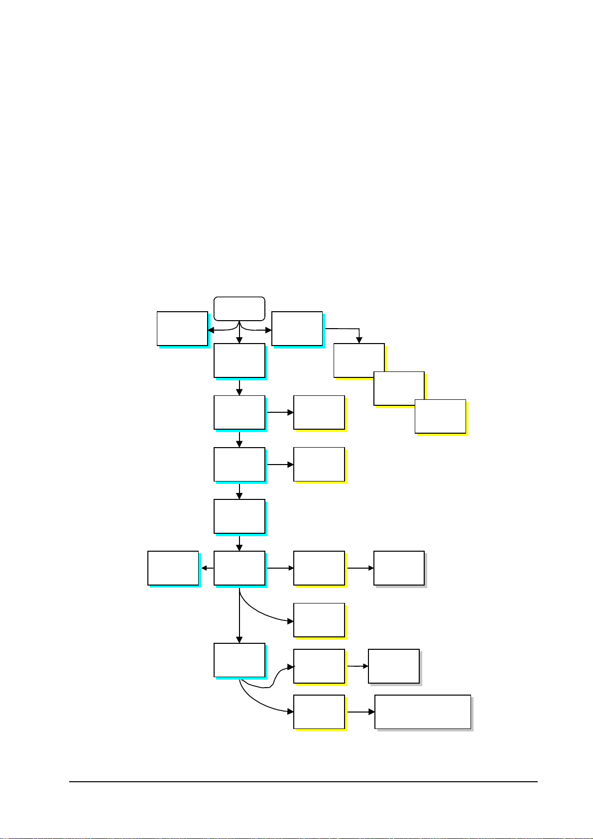
Disassembly road map
The diagram on page 5-5 is intended to give an idea on what order to be followed to reach the
component. For example, in order to remove the drum unit, the toner container, developer unit,
and the paper feed unit must be removed beforehand.
Disassembly
Disassembly road map
Note.
In most cases, the toner container and the developer unit must be removed in the beginning.
Use the reverse of removal procedures when replacing the component back in the printer. Observe
whatever note provided to give critical handlings.
Warning - Before proceeding, unplug the power cord from the printer and
the power supply.
Warning - Never attempt to operate the printer with a component removed.
Caution - The printer uses electrostatic-sensitive parts inside (on boards, laser scanner, etc.). Provide an antistatic (discharging) device, such as a wrist
strap, that can effectively discharge your body before touching boards, laser scanner, etc.
5-4
FS-1750/FS-3750 Series
Page 5
Disassembly
Disassembly road map
DISASSEMBLY ROAD MAP
Main
board
29
Engine
board
30
Start
6
Developer
unit
15
Drum
unit
18
Top side
cover
19
Left side
door
19
Right side
cover
Numbers refer to the appropriate page in this chapter.
10
Paper feed
unit
10
Multi-
17
Main
charger unit
27
Laser
scanner
20
Drive gears
assembly
purpose tray
12
Transfer
roller
Relay
board
For cleaning, see
page 5-13.
13
Regist.
roller
20
Front panel
21
Fuser unit
Hi-voltage
unit
28
Controller
box
5-5
Sensor
board
29
Connect boards,
power supply
FS-1750/FS-3750 Series
Page 6
Disassembly
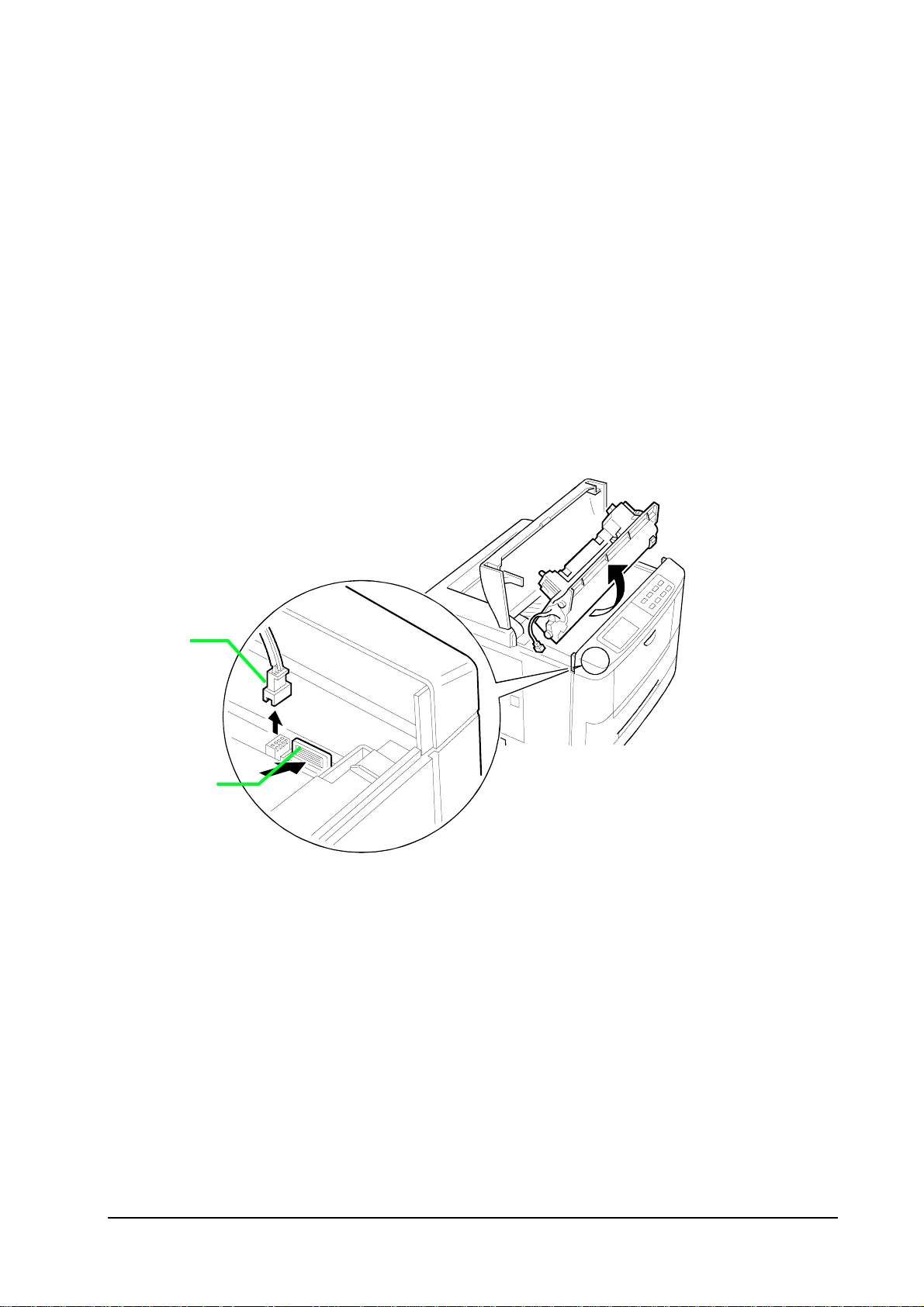
Removing the developer unit
Open the top cover. The toner container ➊ must be removed first : Pul l t he toner cont ainer rel eas e
lever ➋ as below. Pull the toner container slowly up. To avoid toner adhering from spilling, keep it as
level as possible.
Disassembly
Disassembly road map
➊
➋
5-6
FS-1750/FS-3750 Series
Page 7
Disassembly
Disassembly road map
➌
After removing the toner container, remove the developer’s connector ➌
while pressing the developer release lever ➍ towards the front of the printer, remove the developer unit.
from the printer. Then,
➍
Note.
After removing the developer, seal it in the protective bag and place it on a flat surface. Do not
place the developer in a dusty area. If you ship the developer, pack it in the shipping container
specifically supplied with the printer. See
do not touch the developing roller of the developer. Do not place floppy disks near the developer.
Shipping the developer unit
5-7
on page 5-8. Also
FS-1750/FS-3750 Series
Page 8
Disassembly
Disassembly road map
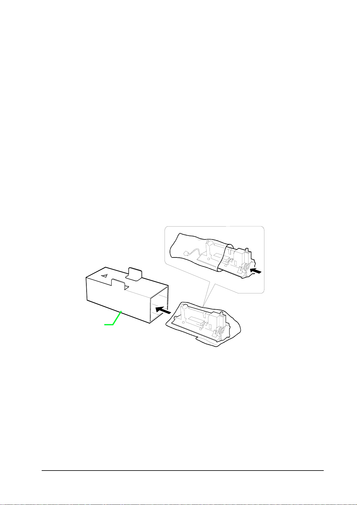
Shipping the developer unit
If the developer unit is shipped (the developer must be shipped separately if the printer is
shipped), it must be fit in the shipping container ➊ supplied originally with th e printer.
First, flap the magnet roller protective cover down. Put the developer unit in the plastic bag supplied with the shipping container. Put the developer unit into the shipping container.
Œ
5-8
FS-1750/FS-3750 Series
Page 9
Disassembly
Disassembly road map
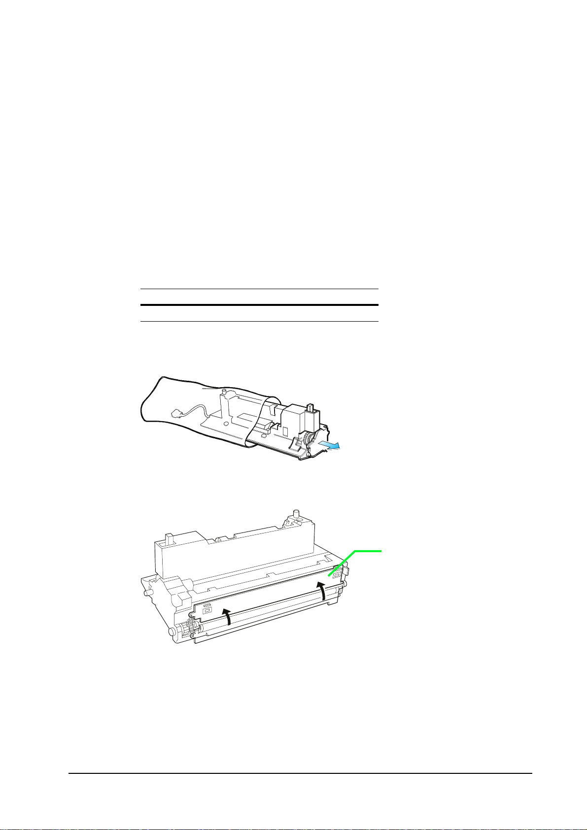
Installing a new developer
Use the following developer kit for replacement. This kit is commonly used with all models.
Kit
Developer unit DV-20
Produce the developer unit from the protective bag.
➊
Flap the magnet roller protective cover ➊ up.
Install the developer using the reverse manner of removing the developer explained above. Con-
nect the developer connector.
5-9
FS-1750/FS-3750 Series
Page 10

Removing the paper feed unit
Disassembly
Disassembly road map
The paper feed unit can be removed from the printer without using tools. First
remove the paper cassette entirely out
out.
To remove the paper feed unit, first remove the paper cassette out. While holding and pushing the
locking tabs Πat both sides of the paper feed unit, draw the paper feed unit all th e way out.
. Otherwise, the paper feed unit will not come
, be sure to
Œ
Removing the multi-purpose tray
To remove the multi-purpose tray ➊, pull the paper feed u nit release lever ➋ up and draw the paper feed unit ➌ out. Then proceed as follows:
5-10
FS-1750/FS-3750 Series
Page 11

Gently fold the
➊
multi-p urpose
tray down.
➌
Disassembly
Disassembly road map
➋
Holding the tray by both ends, pull it up until catches ➍ are released.
➊
➍
5-11
FS-1750/FS-3750 Series
Page 12

Disassembly
Disassembly road map
Removing the transfer roller
Before removing the transfer roller, remove the paper feed unit out of the printer.
Caution - Do not touch the transfer roller (sponge) surface. Oil and dust
(particles of paper, etc.) on the transfer roller can significantly deteriorate
the print quality (white spots, etc.).
Lift the paper shute guide and remove the transfer roller cover ➊.Remove the transfer roller cover
➊. Facing front the paper feed unit, move it to left. Using a small flat blade screw, pull the left end
of the cover.
The transfer roller • is held in place by two axle holders that hold the roller axle at both ends.
Hold and pull the gear Ž at the right end of the roller up, then remove the left end.
Œ
•
Ž
5-12
FS-1750/FS-3750 Series
Page 13

Disassembly
Disassembly road map
CLEANING THE TRANSFER ROLLER
To clean the transfer roller, hold it by its gear so that the roller hangs down horizontally. Use a
vacuum cleaner, moving nozzle along the roller,
touch on the roller
. Thoroughly clean the entire surface of the roller.
but do not let the nozzle directly
REPLACING THE TRANSFER ROLLER
Carefully clean the left side (facing the front of the paper feed unit) axle end before replacing the
transfer roller. This end of the axle is directly applied with the high voltage transfer bias.
Removing the registration rollers
Before removing the registration rollers, remove the paper feed unit out of the printer. See
Removing the paper feed unit
Remove the registration rollers cover ➊. The cover is locked by two catches that lock it onto the
paper feed unit. These catches can be accessed through the holes • on the cover. Insert a screw
driver as shown below and release the locks.
on page 5-10.
•
•
5-13
Œ
FS-1750/FS-3750 Series
Page 14

Disassembly
Disassembly road map
Remove the coil springs Ž that are used to secure and press the top (metal) registration roller
towards the bottom (rubber) registration roller underneath.
Protect your eyes with goggles.
Ž
•
•
5-14
FS-1750/FS-3750 Series
Page 15

Disassembly
y
Disassembly road map
Removing the drum unit
Caution - Before removing the drum unit ➌, be sure to remove the developer
unit ➊ and draw out the paper feed unit ➋ half way. Do not attempt to
forcibly pull out the drum without first having done all of these procedures.
➌
Remove this screw and draw out the
drum unit carefull
.
➊
Remove the developer. See
Removing the developer unit
on page 5-6.
➋
Pull the paper feed unit
halfway out.
Caution - Store the drum unit in a clear, clean place, not exposed to a strong
light source. Seal it in a protective bag. Avoid bump the drum surface onto
hard objects.
5-15
FS-1750/FS-3750 Series
Page 16

Disassembly
Disassembly road map
Replacing the drum unit
To replace the drum unit into the printer, be sure to align the guides and rails on the drum unit
with each other. Do not force to slide the drum unit in unless they are properly aligned with each
other.
Guide on the printer
Holding rails on the
drum unit
Holding rails on the
i
Guide on the drum
unit
5-16
FS-1750/FS-3750 Series
Page 17

Disassembly
Disassembly road map
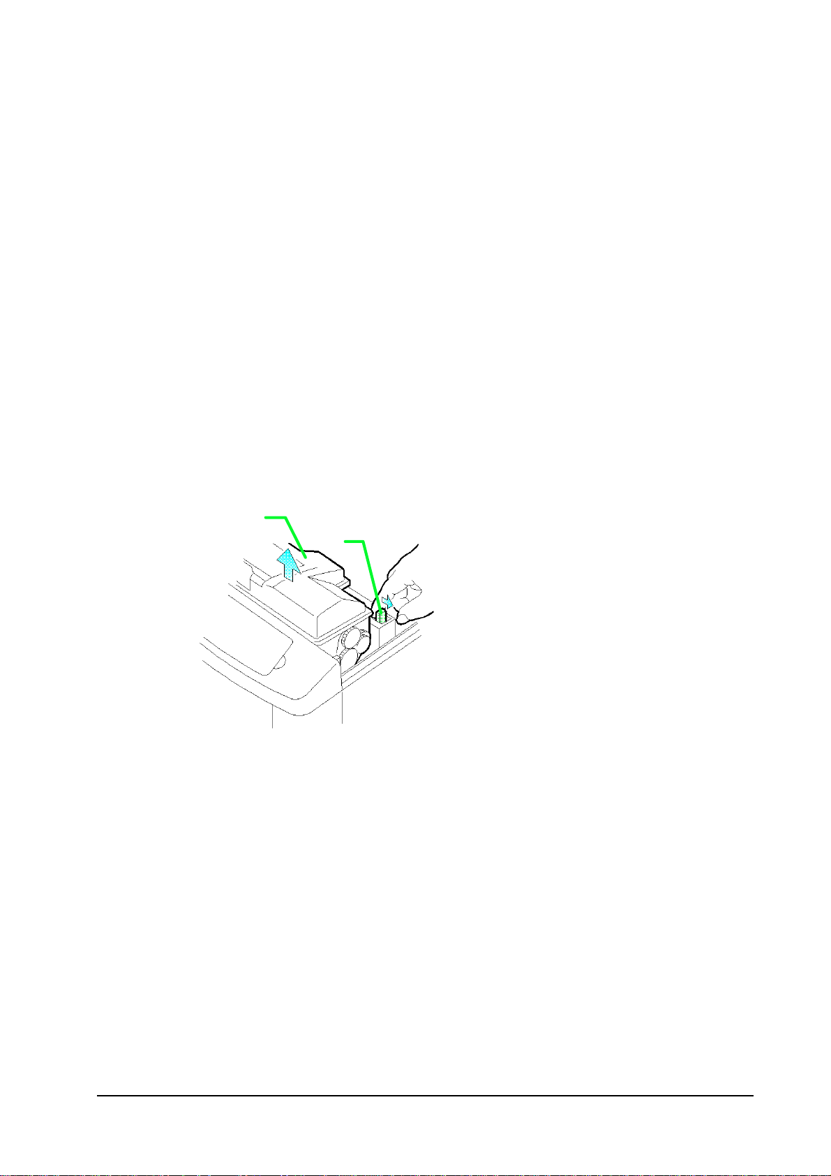
Main charger unit
Pull the main charger ➊ until it stops. While pushing the (white) locking peg ➋ inward s the
printer, pull the main charger unit all the way o ut.
The main charger unit is technically explained in chapter 4, Operation.
➊
➋
5-17
FS-1750/FS-3750 Series
Page 18

Disassembly
Disassembly road map
Top side cover
Open the toner container access door ➊. Remove two screws ➋. While holding the spring-loaded
back side cover ➌ to open, pull the back plane of the top cover away from the printer, then pull it
upwards to remove.
➋
➊
Hold here
backwards
then upwards.
➋
➌
5-18
FS-1750/FS-3750 Series
Page 19

Disassembly
Disassembly road map
Removing covers
The left and right side covers are snapped onto the chass i s by catches and hol es . No sc rews are used.
To remove the left and right side covers, release thos e cat ches and holes at the front ➊ and the rear ➋
from each other, by inserting a small flat blade screw driver between the cover and the chassis. Then,
free the catches at the bottom ➌ by lowering the top side of t he cover downwards .
(USmodels only.)
Front panel
explanation below.)
➎
(See
➍
➊
“
➍
“
➐
➏
➋
➌
➌
➌
5-19
FS-1750/FS-3750 Series
Page 20

Disassembly
Disassembly road map
Removing the front panel
See the picture above. Remove two screws ➍ that secure the front panel to the chassis. Remove
the ground wire from the chassis front ➎. Remove the other ground wire ➏. Unplug th e connector
➐. Release catches “ in four parts. Remove the front panel.
Removing the drive gears assembly
The right side cover must be removed first. Remove s i x s crews . Detach t wo connect ors . Then remove the drive assembly from the printer.
Ground wire from
the front panel
5-20
FS-1750/FS-3750 Series
Page 21

Removing the fuser unit
Disassembly
Disassembly road map
Before removing the fuser unit, remove the covers first (Refer to
Removing covers,
page 5-19.
Warning - The fuser is hot after the printer was running. Wait until it cools
down.
Disconnect plugs first. To remove the fuser uni t remove t wo s crews at the back.
Paper full sensor
(FS-3750 only)
Fuser unit
5-21
FS-1750/FS-3750 Series
Page 22

Disassembly
Disassembly road map
Removing the heater lamp
Warning - The heater is extremely hot immediately after the printer was running. Allow substantial period of time until it cools down. Also, the heater is
fragile: Handle it with great care.
Note.
To remove the heater lamp, remove two screws on the cover at the right s ide of t he fus er unit . R emove the cover. Slightly pulling the terminal outward Œ, so that it bends to free the heater head •,
draw the heater lamp out.
Do not directly touch on the heater lamp. Finger prints on the heater’s outer surface can prevent
proper fusing of toner on paper.
Œ
•
5-22
FS-1750/FS-3750 Series
Page 23

Disassembly
Disassembly road map
Replacing the fuser rollers
Remove four screws ➊ on the top case. Use care not to let the top (heat) roller ➋ fall when lifting the
top case.
➊
C1
➊
C1
➋
5-23
FS-1750/FS-3750 Series
Page 24

Disassembly
Disassembly road map
To gain access to the heat (metal) roller ➌, the roller retaining plate • must be removed. To remove
the retaining plate, use a small flat blade screwdriver inserting it into the gaps as shown in the figure
below.
Caution - Special care should be taken not to let the screwdriver go too far into the hole. Such an action can irrevocably damage the roller surface.
Ž
5-24
•
FS-1750/FS-3750 Series
Page 25

Removing the themostat and thermal cutoff
Disassembly
Disassembly road map
Thermal cutoff
5-25
Thermostat
FS-1750/FS-3750 Series
Page 26

Disassembly
Disassembly road map
Replacing the heat roller
To replace the heat roller, align the protrusions • on both collars so that they face the paper input
side (the drum unit side) [horizontally].
Then insert the heat roller retainer • back in place.
Heat roller
➎
Align the protrusion in a horizontal angle.
Heat roller retainer
➎
5-26
FS-1750/FS-3750 Series
Page 27

Disassembly
Disassembly road map
Removing the laser scanner
To remove the laser scanner, the top cover must be removed first. Fo r details on removing the top
cover, refer to
Removing covers
on page 5-19.
Warning - The laser scanner contains electrostatic-sensitive parts inside (laser
diode, etc.). Before touching the laser scanner, provide an antistatic (discharging) device, such as a wrist strap, that can effectively discharge your
body.
To remove the laser scanner ➊, remove a connector ➋. Remove three screws.
the scanner, handle it carefully.
After removing
➊
➋
5-27
FS-1750/FS-3750 Series
Page 28

Disassembly
Disassembly road map
Removing the controller box
Before removing the controller box, the following parts must be removed in the order indicated.
(For details on removing these parts, refer to the page enclosed by brackets.)
• Developer (Page 5-6)
• Drum unit (Page 5-15)
• Top side cover (Page 5-18)
• Left side cover (Page 5-19)
• Right side cover (Page 5-19)
• Front panel (Page 5-19)
Remove the connectors, then remove the screws as shown in the diagram below.
5-28
FS-1750/FS-3750 Series
Page 29

Disassembly
Disassembly road map
Removing the engine board
In prior to removing the engine board, remove the following parts (For details on removing these
parts, refer to the page enclosed by brackets.):
• Top side cover (Page 5-5-18)
• Right side cover (Page 5-5-19)
• Memory card [if inserted in the slot]
• Main controller board [Remove three screws securing the board to the rear panel.]
To remove the engine board ➊, remove two connectors ➋; then remove a screw
the engine board slowly along the rails.
D10
. Draw out
D10
➊
Use the reverse procedure to replace the engine board back in the printer.
➋
5-29
FS-1750/FS-3750 Series
Page 30

Removing the main circuit board
Remove the three screws from the printer’s rear cover.
Disassembly
Disassembly road map
Power OFF (O)
Pull the main circuit board all the way out of th e printer.
5-30
FS-1750/FS-3750 Series
 Loading...