

Page 1

Troubleshooting
Board layouts
Chapter Six
TROUBLESHOOTING
6-1
FS-1750/FS-3750 Series
Page 2

Troubleshooting
Board layouts
Chapter Six
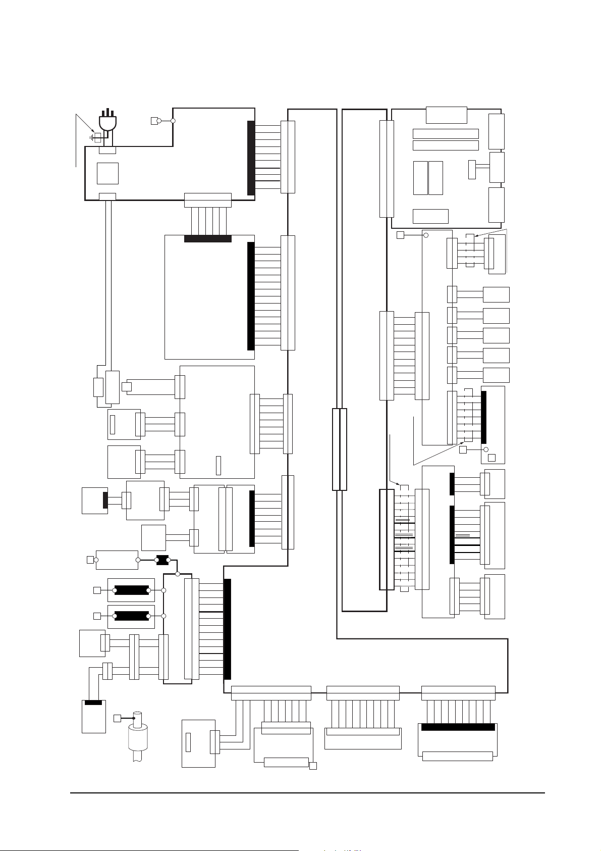
Board layouts 6-4
Liaison board/KP-504 6-4
Scanner interface board/KP-488 6-5
Engine board connectors/KP-535 6-5
Fuser board/KP-499 6-6
Drum connector/YC-741 (KP-500 board) 6-6
General wiring diagram ➊ 6-76-6
General wiring diagram ➋ 6-8
Diagnostic 6-9
Engine diagnostics flow 6-10
Logic controller diagnostics flow 6-11
General error handling 6-12
Priority 6-12
User-recoverable errors 6-14
Memory card errors 6-17
Service errors 6-19
E0 - Communication error 6-19
E1 - Main motor error 6-19
E2 - Laser scanner motor error 6-21
E3 - Laser beam detection error 6-23
E4 - Fuser heater error 6-25
E5 - Eraser error 6-27
E6 - Flash ROM error 6-29
E9 - Toner motor error 6-29
F0 - Front control panel error 6-31
F1 - System ROM error 6-31
F2 - Main memory error 6-31
F3 - General failure 6-31
False errors - “Paper Feed Unit Open” 6-32
False errors - “Top Cover Open” 6-33
False errors - “Side cover Open” 6-34
False errors - “Missing Waste-toner bottle” 6-35
TROUBLESHOOTING6-1
Print quality problems 6-36
Completely blank printout 6-36
All-black printout 6-36
Dropouts 6-37
Black dots 6-38
Horizontal streaks 6-38
Black vertical streaks 6-39
Unsharp printing 6-39
Grey background 6-40
Dirt on the top edge or back of the paper 6-41
REPETITIVE DEFECTS GAUGE 6-43
6-2
FS-1750/FS-3750 Series
Page 3

CHECKING CASSETTE SIZE SENSORS 6-44
Drum cleaning 6-45
Troubleshooting
Board layouts
6-3
FS-1750/FS-3750 Series
Page 4
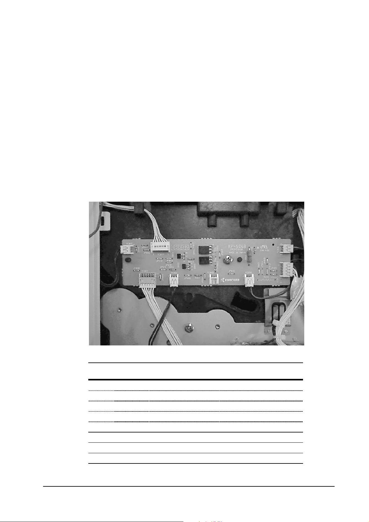
Board layouts
Relay board/KP-504
Troubleshooting
Board layouts
Symbol
(above)
➊
➋
➌
➍
➎
➏
➐
➑
Connector Connected to: Check point
YC806 Fan (large)
YC802 Main motor E1, Pin 3 (MOTOR*)/Pin 1 (+24V)
YC808 Fan (small)
YC803 Registration clutch
YC804 Paper feed clutch
YC801 Engine board E1, Pin 12 (MOTOR*)
YC805 Manual feed clutch
YC807 Front operator panel
6-4
FS-1750/FS-3750 Series
Page 5
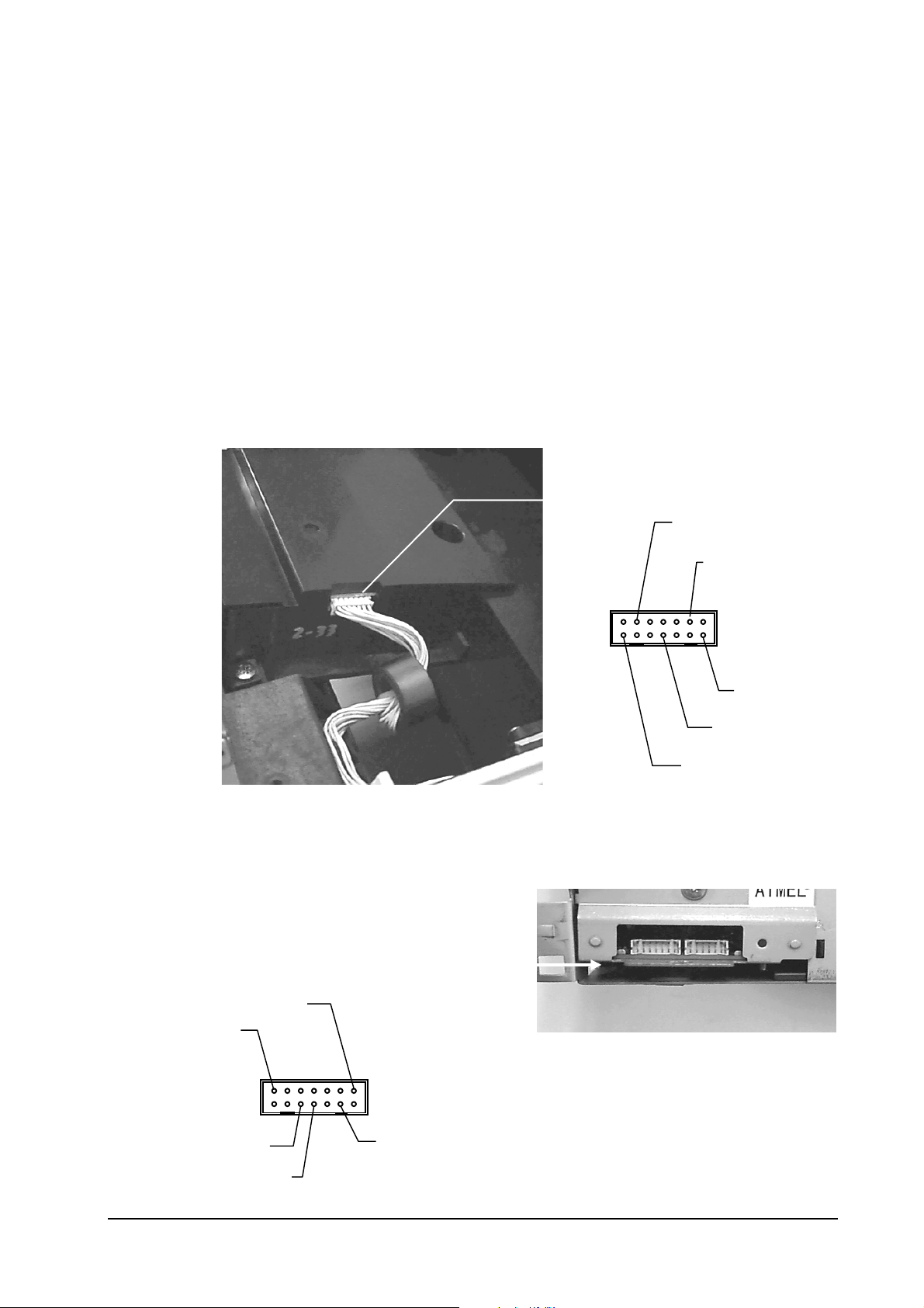
Scanner interface board/KP-488
Troubleshooting
Board layouts
YC675
4 - SCANR*
Engine board connectors/KP-669
+24V - 13
10 - PD*
13 - LASR*
7 - DSCLK
1 - +24V
YC203 (To
scanner
unit)/See
LASR* - 1
PD* - 6
SCNCLK - 8
12 - SCANR*
6-5
FS-1750/FS-3750 Series
Page 6
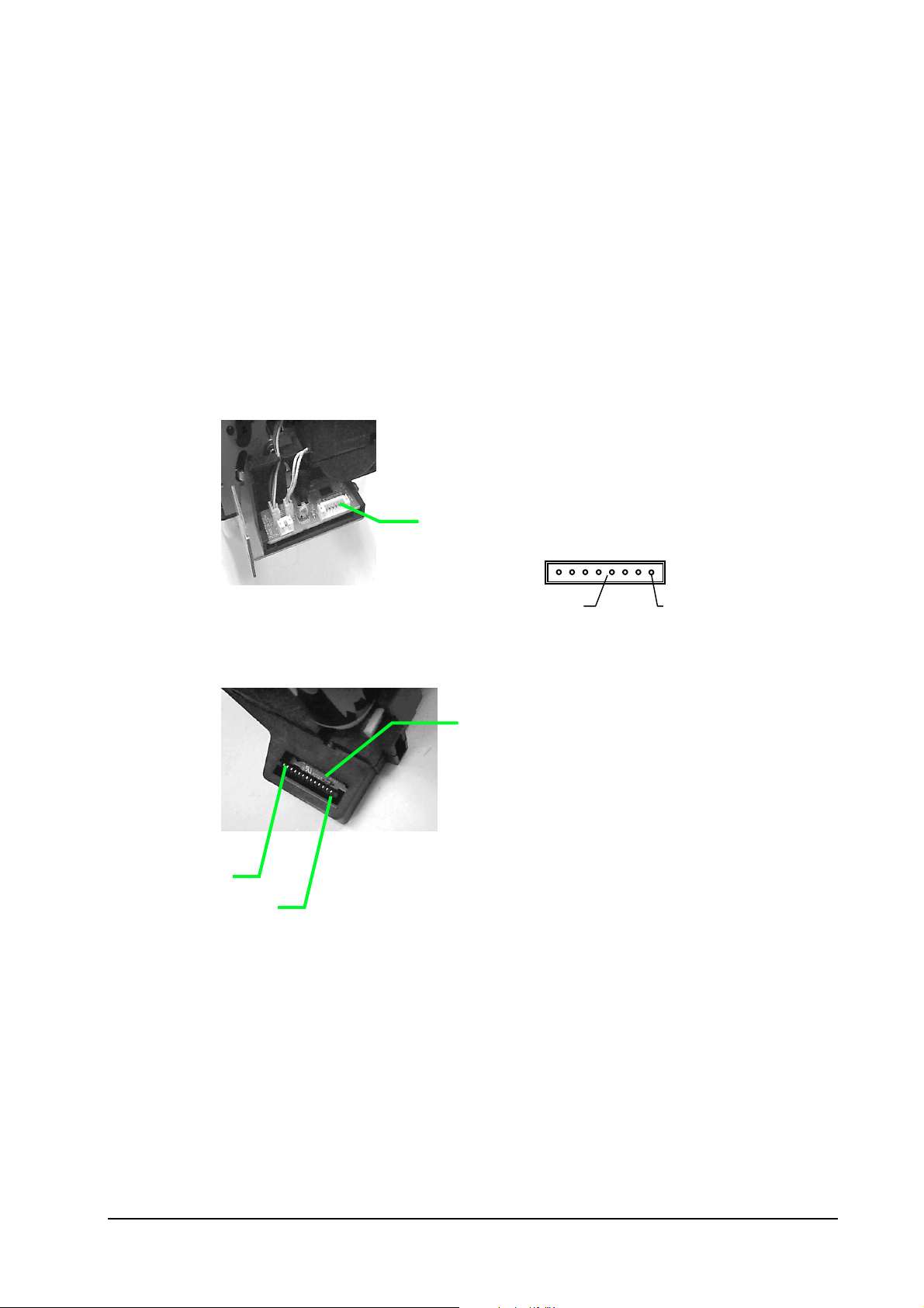
Fuser board/KP-499
Troubleshooting
Board layouts
Drum connector/YC-741 (KP-500 board)
Pin 13
Pin 1
YC721 (➲KP-492)
5 - THERM* 8 - +5V
KP-500 board
6-6
FS-1750/FS-3750 Series
Page 7
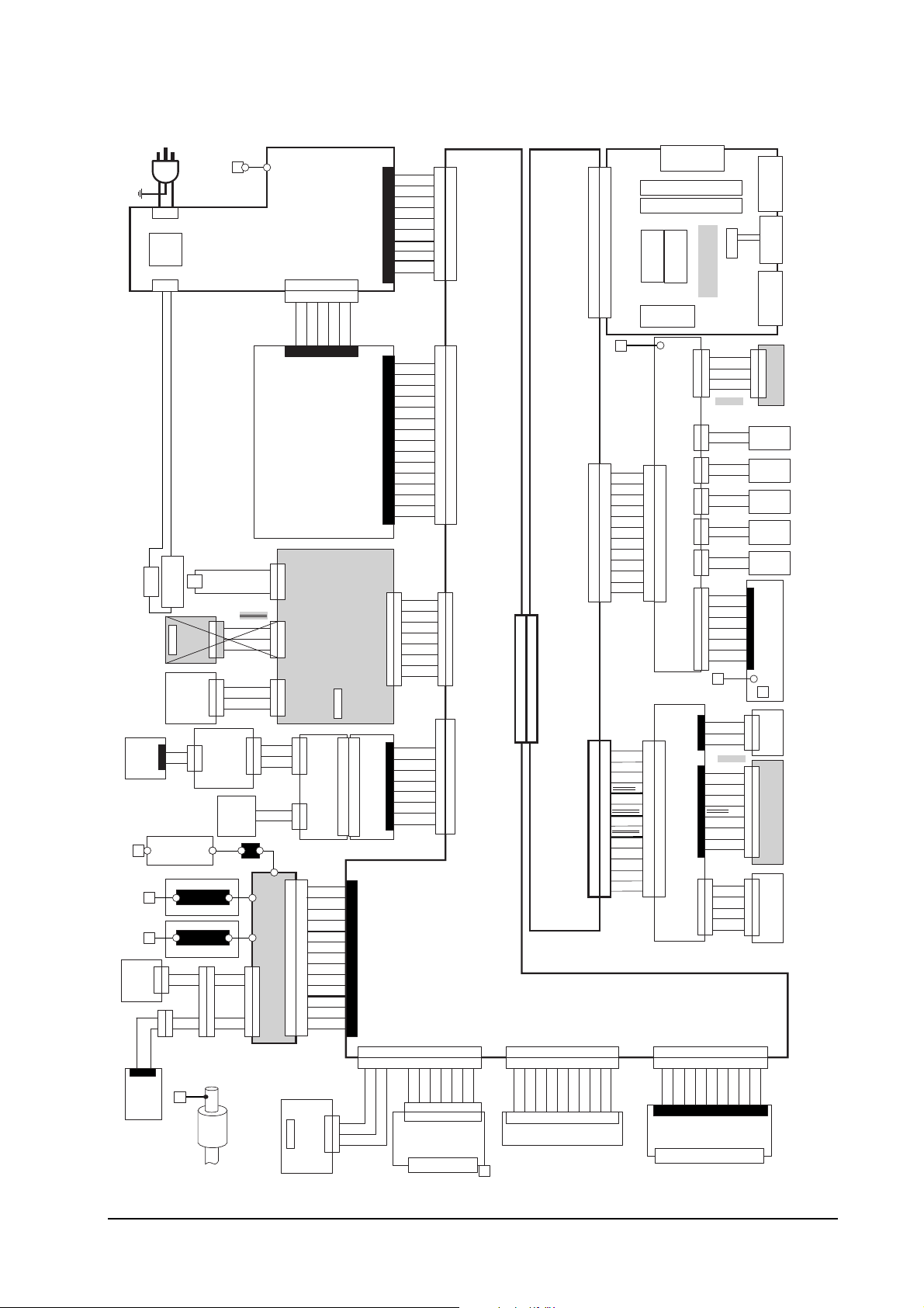
General wiring diagram(FS-1750)
AC IN
S02013
1
2
(CN1)
SWITCH
1
2
(CN2)
S02039 : E
S02012 : U
THERMO CUT OUT
HEATER
SENSOR
FULL
SOLENOID
UP/DOWN
S02021
SENSOR
C
1
E
2
2
ZENER PWB
(KP-501)
TRANSFER ROLLER
MAG ROLLER
TONER
SENSOR
TNEND*
2
2
GND
1
1
TDRV
2
2
+24V
1
1
S02029
S02023
TONER
MOTOR
S02036
POWER
THERMISTER
THERM*
S02019
PAPAER
+5V
1
1
PAPFL*
2
2
GND
3
3
FCUP*
FACE
1
1
+24V
2
2
FDOWN*
3
3
TNFULL PWB
(KP-506)
(YC841)
(YC842)
121
ERASER
TNEND*
1
1
GND
2
2
TDRV
3
3
+24V
4
4
S02022
FEED ROLLER
+5V
1
1
2
2
1
1
2
2
3
3
1
1
2
2
3
3
S02018
+5V
1
1
TNFULL*
2
2
TSEN*
3
3
S02043
ERASER
GND
1
2
HIGH VOLTAGE UNIT
3
4
5
6
7
8
1
1
9
2
2
10
11
12
(CN1)
(CN2)
5
5
13
6
6
14
MANUAL PAPER
POWER SUPPLY UNIT
(CN4)
1
1
6
+24V
(YC702)
+24VCOM
+24VCOM
+24VCOM
SENSOR PWB
(KP-498)
(YC723) (YC724) (YC722)
FUSER PWB
(KP-499)
(YC743)
(YC741)
1
1
2
2
DRUM PWB
3
3
(KP-500)
(YC742)
121
121
2
2
S02381
(旧S02008)
+24V
1
MHVDR*
2
THVDR*
3
HVMON*
4
HVISEL
5
HVCK
6
PSEL*
7
TEND
8
+5V
9
GND
10
MICR
11
GND
12
SCAN
13
MDRV
14
PAPER SENSOR
MANUAL FEED
3
3
2
2
1
1
GND
PD*
+5V
65432
65432
+5V
12345
1
2
3
4
5
6
7
8
9
10
11
12
13
14
1
2
3
4
(CN3)
5
6
7
8
9
10
(旧 S02011)
S02385
1
2
3
4
5
6
(YC701)
7
8
9
10
11
12
13
14
15
1
2
(YC721)
3
4
5
6
7
8
(YC821)
(YC822)
1
1
2
2
3
DRUM RELAY
PWB
3
4
4
5
5
(KP-505)
6
6
7
7
8
8
(YC355)
10
8
9
10
8
9
HANDS*
+5V
GND
S02382
GND
1
GND
GND
+5V
+5V
+5V
ZCROSS
HEAT*
PSAVE
+24V
(旧S02010)
SCOVER*
PAPER*
FEEDS*
TNCON*
+24V
+24V
+24V
+24V
FCOVER*
TCOVER
CAST2
CAST1
CAST0
GND
1
2
3
4
5
6
7
8
(旧S02007)
TSEN*
TNFULL*
ERASER
EECSEL
EEDAT
EESCK
GND
+5V
(YC381)
(YC382)
1
2
2
3
3
(YC352)
4
4
5
5
6
6
7
7
8
8
9
9
10
10
S02384
1
1
2
2
3
3
4
4
5
5
6
6
7
(YC358)
7
8
8
9
9
10
10
11
11
12
12
13
13
14
14
15
16
1
1
2
2
3
3
4
4
5
5
6
6
7
7
8
8
10
EPAP*
1
2
3
4
5
6
7
8
9
(YC353)
(YC356)
EMOT*
EUNIT*
(KP-502)
(KP-701)
1234567
1234567
+24V
1234567
1234567
CONNECT PWB
(YC351)
10
10
S02386(旧 S02016)
GND
10
S02036
15
16
S02009
FCUP*
+24V
FDOWN*
PAPFL*
THERM*
EXITJ*
GND
+5V
S02380
1
2
3
4
5
6
7
8
9
10
(YC357) (YC354)
GND
HANDS*
PUNIT*
ENVEROP
FEEDER
PWB
To PF-7E
Engine Controller
(KP-699)
(YC202)
SEL10
SEL11
SEL12
SDATI
SDATO
To OPTION UNIT
(YC201)
(YC204)
10
11
12
(YC203)
10
11
12
13
14
REDY
1
2
3
4
5
6
7
8
9
1
2
3
4
5
6
7
8
9
+5V
1
2
3
4
5
6
7
8
9
10
11
12
1
2
3
4
5
6
7
8
9
10
11
12
13
14
SCLK*
(YS1)
(YS2)
(YC1)
(YS3)
S02020
GND
FPCLK
FPDIR
FPDATA
+5V
FAN*
FEDDR*
MFDDR*
MTRCLK
REGDR*
MOTOR
+24V
S02046
LASER*
LONB*
VDO+
+5V
VDOPD*
LSGND
SCNCLK
LSGND
SCRDY*
GND
SCANR*
+24V
GNDP
123456789
123456789
+24V
123456789
(YC4)
S02038
10
12
11
13
14
11
12
10
S02383(旧 S02015)
PC-Card
PC-SIMM
PC-SIMM
PowerPC603e
-100MHz
XLI
ROM (DIMM)
(KP-710)
RELAY PWB
(KP-504)
2
2
1
1
4
4
3
3
6
6
5
5
8
8
7
7
10
9
9
12
11
(YC801)
13
14
APC RELAY PWB
11
12
9
9
10
7
7
8
8
(KP-488)
5
5
6
6
3
3
4
4
1
1
2
2
(YC675)
10
10
+24V
GND
10
(YC354)
(YC371)
Troubleshooting
Board layouts
Centronics
(YC2)
(KP-725)
(YC3)
FUP*
S02044
1
2
3
4
5
6
7
1
2
3
1
2
3
4
5
6
7
8
1
2
3
4
5
FOP*
(YC5)
1
1
1
2
2
2
3
3
3
4
4
4
Regist
Clutch
Feed
Clutch
M.Feed
Clutch
Motor
Box Fan
Motor
1
2
3
1
2
3
4
5
6
7
8
1
2
3
4
5
123456789
123456789
MON*
123456789
RS-232C
OPTION I/F
Main Motor
Fan
Front Panel
(KP-503)
S02037
PD PWB
(KP-483)
APC PWB
(KP-705)
Polygon Motor
VLOW*
S02014
Main Controller
(KP-724)
+24V
(YC802)
1
1
GND
2
2
MOTOR*
3
3
MTRCLK
4
4
S02047
(YC803) (YC804) (YC805) (YC806)
+24V
1
1
REGDR*
2
2
+24V
1
1
FEDDR*
2
2
+24V
1
1
MFDDR*
2
2
FANCOM
1
1
FANDR*
2
2
(YC808)
BFANCOM
1
1
BFANDR*
2
2
S02001
+5V
1
1
FPDAT
2
2
+5V
(YC807)
3
3
FPDIR
4
4
GND
5
5
FPCLK
6
6
GND
7
7
S02025
(YC674)
+5V
1
PD*
2
GND
3
+5V
1
LONB*
2
LASR*
3
(YC673)
VDO+
4
VDO-
5
LSGND
6
LSGND
7
GND
8
+24V
1
1
GND
(YC671)
2
2
SCANR*
3
3
SCRDY*
4
4
SCNCLK
5
5
(YC359)
HSCOPN
HSPAP*
UNIT*
FUX PWB
(KP-493)
To HS-20
S02006
S02004
S02005
(GND)
6-7
FS-1750/FS-3750 Series
Page 8
General wiring diagram(FS-3750)
Troubleshooting
Board layouts
TDK HF70T18*6*10
1
2
1
2
THERMO CUT OUT
HEATER
S02021
SENSOR
C
1
E
2
ZENER PWB
(KP-501)
TRANSFER ROLLER
TONER
SENSOR
TNEND*
2
2
GND
1
1
2
2
1
1
S02029
TONER
MOTOR
AC IN
S02013
(CN1)
POWER
SWITCH
(CN2)
S02039 : E
S02012 : U
THERMISTER
SENSOR
PAPAER
FULL
SOLENOID
UP/DOWN
FACE
(YC842)
121
2
MAG ROLLER
1
2
TDRV
3
+24V
4
S02023
S02036
+5V
1
1
PAPFL*
2
2
GND
3
3
FCUP*
1
1
+24V
2
2
FDOWN*
3
3
TNFULL PWB
(KP-506)
ERASER
TNEND*
1
GND
2
TDRV
3
+24V
4
S02022
FEED ROLLER
1
1
6
+5V
(YC723) (YC724) (YC722)
1
1
THERM*
2
2
S02019
1
1
2
2
3
3
1
1
2
2
3
3
S02018
(YC841)
+5V
1
1
TNFULL*
2
2
TSEN*
3
3
S02043
ERASER
GND
1
2
HIGH VOLTAGE UNIT
3
4
5
6
7
8
1
1
9
2
2
10
11
12
(CN1)
(CN2)
5
5
13
6
6
14
MANUAL PAPER
POWER SUPPLY UNIT
(CN4)
+24VCOM
+24VCOM
+24VCOM
+24V
(YC702)
SENSOR PWB
(KP-498)
FUSER PWB
(KP-499)
(YC743)
(YC741)
1
1
2
2
DRUM PWB
3
3
(KP-500)
(YC742)
121
121
2
2
S02381
+24V
1
MHVDR*
2
THVDR*
3
HVMON*
4
HVISEL
5
HVCK
6
PSEL*
7
TEND
8
+5V
9
GND
10
MICR
11
GND
12
SCAN
13
MDRV
14
PAPER SENSOR
MANUAL FEED
GND
3
3
PD*
2
2
+5V
1
1
65432
65432
12345
10
11
12
13
14
+5V
1
2
3
4
5
6
7
8
9
(旧 S02011)
(YC821)
PWB
(KP-505)
(YC355)
10
10
GND
1
GND
2
GND
3
+5V
4
(CN3)
+5V
5
+5V
6
ZCROSS
7
HEAT*
8
PSAVE
9
+24V
10
S02385
SCOVER*
1
PAPER*
2
FEEDS*
3
TNCON*
4
+24V
5
+24V
6
(YC701)
+24V
7
+24V
8
FCOVER*
9
10
TCOVER
11
CAST2
12
CAST1
13
CAST0
14
GND
15
FCUP*
1
1
+24V
2
2
FDOWN*
(YC721)
3
3
PAPFL*
4
4
THERM*
5
5
EXITJ*
6
6
GND
7
7
+5V
8
8
S02380
(YC822)
TSEN*
1
1
TNFULL*
2
2
ERASER
3
DRUM RELAY
3
EECSEL
4
4
EEDAT
5
5
EESCK
6
6
GND
7
7
+5V
8
8
8
9
8
9
HANDS*
+5V
GND
(YC381)
(YC382)
S02382
1
1
2
2
3
3
(YC352)
4
4
5
5
6
6
7
7
8
8
9
9
10
10
S02384
1
1
2
2
3
3
4
4
5
5
6
6
7
(YC358)
7
8
8
9
9
10
10
11
11
12
12
13
13
14
14
15
16
1
2
3
4
5
6
7
8
10
EPAP*
1
2
3
4
5
6
7
8
1
2
3
4
5
6
7
8
9
EUNIT*
(KP-502)
CONNECT PWB
(KP-701)
(YC353)
(YC356)
1234567
1234567
+24V
EMOT*
1234567
1234567
S02386(旧 S02016)
S02036
(YC351)
10
10
GND
10
(YC202)
SDATI
SDATO
To OPTION UNIT
15
16
S02009
1
2
3
4
5
6
7
8
9
10
(YC357) (YC354)
GND
HANDS*
PUNIT*
ENVEROP
FEEDER
PWB
To PF-7E
(YC201)
Engine Controller
1
1
2
SEL11
(YC203)
SEL10
(YC204)
10
11
12
10
11
12
13
14
REDY
2
3
3
4
4
5
5
6
6
7
7
8
8
9
9
10
11
12
TDK HF70T25*13*15
1
1
2
2
3
3
4
4
5
5
6
6
7
7
8
8
9
9
10
11
12
13
14
SCLK*
+5V
(KP-699)
SEL12
(YS1)
(YS2)
(YC1)
(YS3)
S02020
GND
FPCLK
FPDIR
FPDATA
+5V
FAN*
FEDDR*
MFDDR*
MTRCLK
REGDR*
MOTOR
+24V
S02046
LASER*
LONB*
VDO+
+5V
VDOPD*
LSGND
SCNCLK
LSGND
SCRDY*
GND
SCANR*
+24V
GNDP
123456789
123456789
+24V
123456789
(YC4)
XLI
ROM (DIMM)
(KP-710)
S02038
(KP-504)
2
2
1
1
4
4
3
3
6
6
5
5
8
8
7
7
10
10
9
9
12
12
11
11
(YC801)
TDK HF70T18*6*10
13
13
14
14
11
11
12
12
9
9
10
10
7
7
8
8
5
5
6
6
3
3
4
4
1
1
2
2
(YC675)
10
10
S02383(旧 S02015)
10
(YC354)
(YC371)
PC-Card
PC-SIMM
PC-SIMM
PowerPC603e
Main Controller
-166MHz
(KP-707)
+24V
(YC802)
1
1
GND
2
2
MOTOR*
3
3
RELAY PWB
MTRCLK
4
4
S02002
(YC803) (YC804) (YC805) (YC806)
+24V
1
1
REGDR*
2
2
+24V
1
1
FEDDR*
2
2
+24V
1
1
MFDDR*
2
2
FANCOM
1
1
FANDR*
2
2
(YC808)
BFANCOM
1
1
BFANDR*
2
2
S02001
+5V
1
1
FPDAT
2
2
+5V
(YC807)
3
3
FPDIR
4
4
GND
5
5
FPCLK
6
6
GND
7
7
S02025
(YC674)
+5V
1
PD*
2
GND
3
APC RELAY PWB
+5V
1
LONB*
2
LASR*
3
(YC673)
VDO+
4
VDO-
5
LSGND
6
LSGND
(KP-488)
7
GND
8
+24V
5
5
GND
(YC671)
4
4
SCANR*
3
3
SCRDY*
2
2
SCNCLK
1
1
(YC359)
HSCOPN
HSPAP*
UNIT*
+24V
GND
(KP-493)
To HS-20
(YC3)
S02006
S02044
S02005
FUP*
(GND)
S02044
1
2
3
4
5
6
7
1
2
3
1
2
3
4
5
6
7
8
5
4
3
2
1
FOP*
(YC2)
(YC5)
1
1
1
2
2
2
3
3
3
4
4
4
Regist
Clutch
Feed
Clutch
M.Feed
Clutch
Motor
Box Fan
Motor
1
2
3
1
2
3
4
5
6
7
8
5
4
3
2
1
123456789
123456789
MON*
123456789
Centronics
(KP-708)
RS-232C
OPTION I/F
TDK HF70T18*6*10
Main Motor
Fan
Front Panel
(KP-503)
S02037
PD PWB
(KP-483)
APC PWB
(KP-482)
Polygon Motor
VLOW*
S02014
6-8
FS-1750/FS-3750 Series
Page 9

Diagnostic
Troubleshooting
User-recoverable errors
The printer automatically executes its self-diagnostic test when it is powered up (displaying Selftest). The sequence and the items to be diagnosed are explained below.
When the printer locates the error with a specific item, it calls for o perator’s attention by showing
the appropriate message on the operator panel display.
The diagnostic test is done on the following systems simultaneously:
• Engine system (
• Controller system (
Flowcharts on the following pages show the order and the items diagnosed in each system.
Note. Diagnostic test is cancelled if one of the user-accessible covers is opened
during the test.
errors)
E
errors)
F
6-9
FS-1750/FS-3750 Series
Page 10
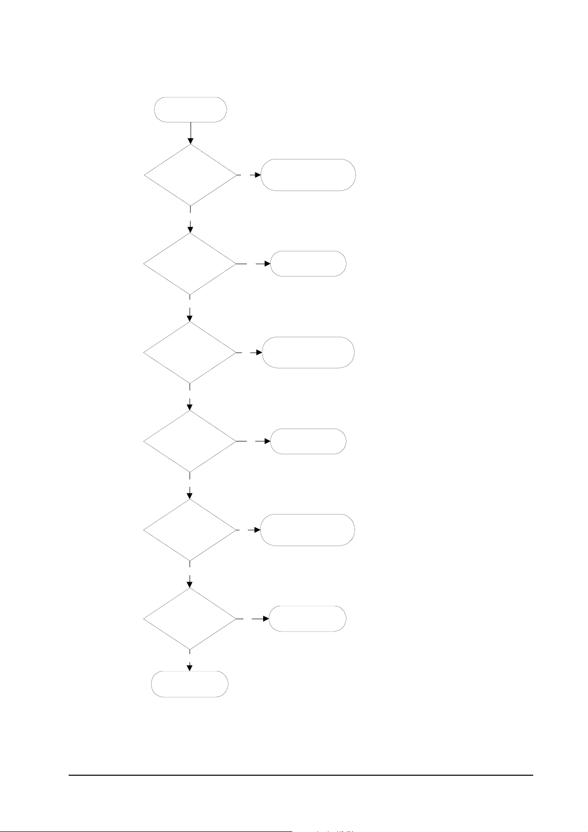
Engine diagnostics flow
Power on
Troubleshooting
User-recoverable errors
1
2
Engine ROM cheksum
OK?
Yes
3
Fuser thermistor OK?
The heater lamp is turned on.
Yes
The scanner polygon motor revolves.
4
Polygon motor OK?
The polygon motor stops revolving.
Yes
The main motor revolves.
The eraser array turns on.
5
Eraser array OK?
No
No
E6 - Engine ROM error
No
No
9
10
E4 - Fuser error
11
E2 - Polygon motor
error
12
E5 - Eraser error
Yes
The eraser array turns off.
6
Main motor OK?
Yes
7
Heater temperature
OK?
The main motor turns off.
Yes
8
Engine is ready.
No
No
13
E1 - Main motor error
14
E4 - Heater error
6-10
FS-1750/FS-3750 Series
Page 11
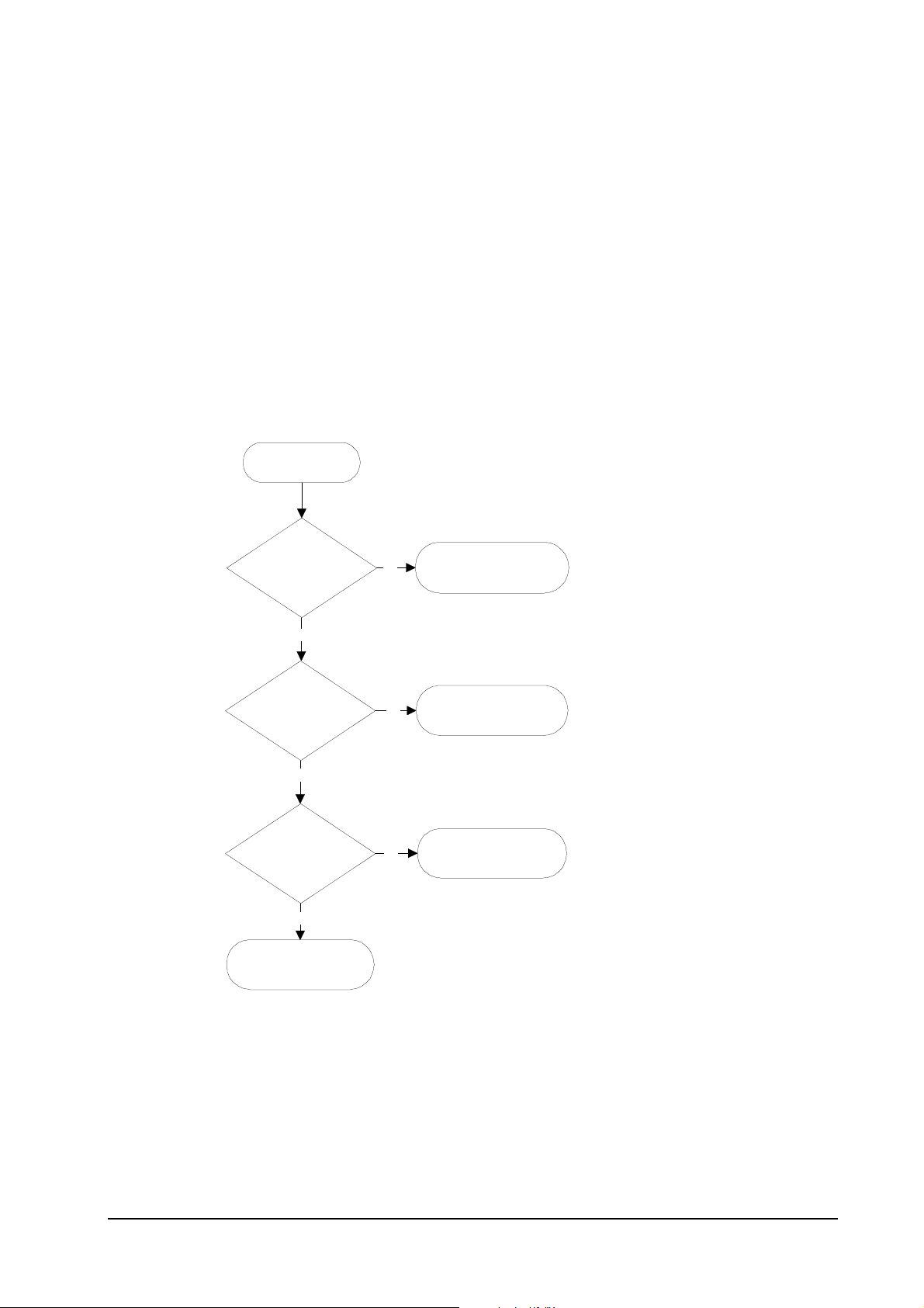
Logic controller diagnostics flow
1
Power on
Troubleshooting
User-recoverable errors
2
System ROM cheksum
OK?
Yes
3
Communication
established between
engine and main
CPUs?
Yes
4
System memory OK?
Yes
5
Controller is ready.
No
No
No
6
F1 - System ROM error
7
E0 - Communication
error
8
F2 - System memory
error
For details on how to react to the results of diagnostics, refer to section
Service errors
on page 6-19.
6-11
FS-1750/FS-3750 Series
Page 12
General error handling
Priority
Each error message has a priority over the others. Thus, if two or more error messages are given
simultaneously, the error message having the highest priority is shown. The priority is as follows
(from the highest to the lowest):
Troubleshooting
General error handling
❂
=Short audio alarm/✺=Long audio alarm
Error message Category Remarks
Call service person …
Call service person F0
I/F occupied
Top cover open
Paper feed unit open
Side cover open
Paper handler cover open
Option stacker cover open
Opt. Feeder 1 (2) rear cover
open
Opt. Stacker unit rear cover
open
Duplex unit rear cover open
Replace Toner/Clean printer❂
Missing Waste-toner bottle
Replace Waste-toner bottle❂
Service error See
Service error See
User-recoverable error If not user-recoverable, see
User-recoverable error If not user-recoverable, see
User-recoverable error If not user-recoverable, see
User-recoverable error When a HS-20/HS-21 is installed.
User-recoverable error When a HS-3E is installed.
User-recoverable error When a PF-20/PF-21 is installed.
User-recoverable error When a SO-6/ST-20 is installed.
User-recoverable error When a DU-20/DU-21 is installed.
User-recoverable error
User-recoverable error If not user-recoverable, see
User-recoverable error
Diagnostics
Diagnostics
“Top Cover Open”
“Paper Feed Unit Open”
“Side cover Open”
“Missing Waste-toner bottle”
section.
section.
, page 6-33.
, page 6-32.
, page 6-34.
False errors -
False errors -
False errors -
False errors -
, page 6-35.
Clean printer … Press CONTINUE❂
Paper jam❂
Remove Opt. Stacker paper❂
Option Stacker paper full❂
Face-down tray paper fill❂
Paper path error❂
User-recoverable error
User-recoverable error
User-recoverable error
User-recoverable error HS-3E
User-recoverable error FS-3750 only
User-recoverable error
6-12
FS-1750/FS-3750 Series
Page 13
Error message Category Remarks
MEMORY CARD err Insert again
Insert the same MEMORY CARD
Print Cancel?
Memory overflow … Press
CONTINUE❂
Print overrun … Press CONTINUE❂
KPDL error … Press CONTINUE❂
MEMORYCARD err … Press
CONTINUE❂
Opt. ROM error … Press
CONTINUE❂
Troubleshooting
General error handling
User-recoverable error
User-recoverable error
User-recoverable error
User-recoverable error
User-recoverable error
User-recoverable error
User-recoverable error
Set paper/Press CONTINUE❂
Load paper❂
Add paper✺
Self test
Sleeping
Please wait
PJL OPMSG/STMSG
Processing
Waiting
FormFeed TimeOut
Option interface Error
Toner low TK-20/Clean printer
Warning/Low memory
Battery error/MEMORY CARD
Format error/MEMORY CARD
Warning battery/MEMORY CARD
Ready
User-recoverable error
User-recoverable error
User-recoverable error
-
-
-
-
-
-
User-recoverable error
User-recoverable error
User-recoverable error
User-recoverable error
User-recoverable error
—
6-13
FS-1750/FS-3750 Series
Page 14
User-recoverable errors
User-recoverable errors do not normally require a service call unless the suggested remedy does
not solve them. The instructions below indicate how to respond to problems indicated by the
operator panel symbolic indicators and by the panel display.
Troubleshooting
User-recoverable errors
Indicator Corrective action
ATTENTION
Message Corrective action
Flashing
Lit
Fast flashing
Slow flashing
Lit
Flashing
Lit
The printer has run low on toner. The toner should be replaced as soon as
possible.
Install a new toner kit. S ee chapter 1.
There is a paper jam. There is a possibility that paper may be jammed at the
point indicated by flashing, open and remove any jammed paper. See
Section
The paper has run out in the paper cassette or multi-purpose tray. Please
insert paper. See Section
This indicates either the current paper feeder or the paper output point.
The printer has insufficient memory available or the printer is warming up
(Pleasewait). Confirm the message indicated on the message display. See
Section
Note the maintenance message on the message display and consult Table
Top cover Open
Side cover Open Open the side cover, then close tightly.
Paper feed unit Open Open the paper feed unit, then close tig htly.
Face-down tray pap er full The face-down tray has become full (approx. 250 pages). Remove all
Add paper Add paper to the paper cassette or multi-purpose tray.
Set paper/Press CONTINUE Add a sheet of paper to the multi-purpose tray (
Open the top cover, then close tight ly.
printed pages from t he face-down tray. When the printer senses that the
face-down tray is empty again, it will continues printing into the facedown tray. (Model FS-3750 only)
6-14
manual mode
FS-1750/FS-3750 Series
), and press
Page 15

User-recoverable errors
Message Corrective action
the CONTINUE key.
Troubleshooting
Load paper
Paper jam Open the top cover or the paper feed unit and correct the paper jam (or
Warning low memory The printer's internal memory is running low due to the number of fonts
Toner low TK-20/Cl ean printer Replace the ton er container using a new t oner kit. See Section …
Replace Toner/Clean pri nter Replace the toner con tainer using a new toner kit. The printer d oes not
Clean printer..Press CONTINUE Please clean the inside of the printer. See Section ...This message will be
ReplaceWaste- toner bottle Replace the old waste toner bottle with the new one which is included in
papersize
The paper size does not match. The size of the paper in the cassette is
different to the size specified by the application software or by
PRESCRIBE II. Either put paper of the specified size into the cassette.
See Section 1.4.If the CONTINUE key is pressed, printing will be
resumed. However, if more than one sheet is to be printed, the same
message will again be displayed from the second sheet onward. It is also
possible to abandon printing by pressing the CANCEL key.
paper mis-feeding in the cassette). See Section …
and macros downloaded. Print a status page to see how much user
memory is left, and try deleting unnecessary fonts and macros. See the
PRESCRIBE II DELF and DELM commands explanation in the
programming manual (CD-ROM).
operate when this message is displayed. See section …
displayed when replacing the toner container after the message
ReplaceTonerCleanprinter has been displayed. After cleani ng the inside of
the printer, press the CONTINUE key and the printer will be ready for
printing.
the TK-20/TK-20H toner kit. The message will also be shown if the waste
toner bottle has become full. The waste toner bottle should be replaced
when the message display eventually shows TonerlowTK-20Cleanprinter.
See Section …
Missing Waste-toner bottle Install the waste toner bottle. See Section ... The printer does not operate
when this message is displayed.
Memory overflow..Press CONTINUEThe total amount of data received by the printer exceeds the pr i nter's
internal memory. Try adding more memory (expansion RAM). Press the
CONTINUE key to resume printing. You can abandon printing by the
CANCEL key.
Print overrun..Press CONTINUE The data transferred to the printer was too complex to print on a page.
Press the CONTINUE key to resume printing. (The page may break in
some pages.)You can abandon printing by the CANCEL key.Note: After
this message has been displayed, Page protect mode will be On. To
maintain optimum use of memory during printing, display >Pageprotect
6-15
FS-1750/FS-3750 Series
Page 16

Troubleshooting
User-recoverable errors
Message Corrective action
from the control panel, and re-select Auto.See the printer’s user’s manual.
MEMORY CARD err/Insertagain The memory card is accidentally removed from the printer's memory card
slot during reading. If you continue reading the memory card, insert the
same memory card into th e sl ot again. The printer again reads it from the
beginning of the data.Note: We recommend that you follow the reading
procedure from the beginning to ensure correct reading of the memory
card.
Insert the same MEMORY CARD You have inserted the wrong memory card when the Insertagain message
was displayed. Remove the wrong memory card from the printer's
memory card slot and i nsert the correct memory card. The printer again
reads it from the beginning of the data.
Format error MEMORY CARD This message appears when the printer is in the ready state and the
memory card is not formatted, and therefore cannot be read or written.
Follow the procedure on Section ... to format the card.
Warning battery MEMORY CARD This message appears when the printer is in the ready state and the battery
in the memory card is low. You can still enter the memory card mode, but
the battery should be changed as soon as possible.
MEMORY CARD err/ ##..Press
CONTINUE
>Read fonts Failed The amount of memory available for the fonts header parts of font is too
I/F occupied This message is displayed when you attempt to use the printer's control
Processing PAR FIT A4 FIT (image FITting) flashes to indicate that a loss of raster data occurred
This message appears when an error occurs during access to the memory
card using the PRESCRIBE II ICCD command or from the printer's
control panel (codes 09 and 11 only). The error is indicated by one of the
numbers ## listed under the Memory card errors which follows.
small to load more fonts. Try deleting unnecessary fonts and macros.
panel to change the environmental setti ngs on the interface from which
data are presently being received.
when the data was compressed to be fitted within the currently available
memory. Flashing FIT extinguishes automatically when the job times out;
the printer receives th e next data from the host computer; or if you press
any key on the printer's control panel. Try adding more memory in the
printer to prevent this error.
Processing PAR 600 A4
ê
Processing PAR 300 A4
Change of the resolution indicator from 600 to 300 (flashing) means that
the job in 600-dpi resolution was not able to run within the currently
available memory. The resolution reverts to 600 dpi automatically when
the job times out; the printer receives the next data from the host
computer; or if you press any key on the printer's control panel. Try
adding more memory in the printer to prevent this error.
6-16
FS-1750/FS-3750 Series
Page 17

Memory card errors
Troubleshooting
User-recoverable errors
Error
code
01
02
03
04
05
06
07
08
09
10
11
12
13
14
15
16
17
Applicable card
type
SRAM Card size error (An attempt was made to write data of greater than 16 MB in
size.). Reduce the size of the data to be written from the host computer to 16
MB or less; or, a file name could not be found in the memory card.
SRAM No memory card inserted. Insert a pro per memory card.
SRAM/flash Non PCMCIA card. Replace the card with a PCMCIA card.
SRAM Not RAM card. Use a SRAM-type card if you want to write data to an
memory card.
SRAM Memory card battery error. Replace the memory card's internal battery with a
new one.
SRAM Memory card protect error. Release the write protection on the memory card
when you write data to the memory card.
SRAM Non-Kyocera format. Reformat the memory card using MODE SELECT (See
the printer’s user’s manual).
SRAM Partition name error. Follow instructions given attempt in Chapter 2 to
properly name the destination.
SRAM Memory card data full error (An attempt was made to write data exceed i ng
the capacity of the memory card). Abandon the writing operation on the host
computer first. Press CONTINUE key; when the message turns to Waiting,
press FORM FEED key (Ready).
- Reserved
SRAM Data name full (An attempt was made to write more than 127 destination data
names). Press CONTINUE key (Ready).
- Reserved
Flash Erase logic error with flash memory card. Try replacing the memory card.
Flash Non PCMCIA flash card. Replace the card with a PCMCIA flash card.
Flash Unable to write to the flash memory card due to insufficient printer memory.
Reserved
Reserved
Either delete unnecessary macros or fonts stored in the printer, or extend the
printer's available memory.
Meaning
6-17
FS-1750/FS-3750 Series
Page 18

Troubleshooting
User-recoverable errors
Error
code
18
19
Applicable card
type
Flash Writing error. Try replacing the memory card.
-
For details on memory card availability, see section
Reserved
Meaning
Printer specifications
in chapter 1.
6-18
FS-1750/FS-3750 Series
Page 19

Service errors
The printer does not operate when a message beginning with E, F, or C is displayed. The total
numer of pages printed is also indicated. The message is categorized as follows:
Troubleshooting
User-recoverable errors
Message Corrective action
Call service person E
Call service person F
Call service person C
Call service person D
E0 - Communication error
Meaning Suggested causes Corrective action
Communication between the
engine controller and the main
controller is failed.
E1 - Main motor error
Meaning Suggested causes Corrective action
n:123456
n:123456
n: 123456
n: 123456
Mechanical error (n=0, 1, 2, ...). Follow the appropriate instructions provided
in this section.
Controller error (n=0, 1, 2, ...). Follow the appropriate instructions provided in
this section.
Option equipment error (n=0, 1, 2, …). This message pertains to either the
sorter or duplexer. C1 through C3 are relevant to the duplexer; C4 through
to the sorter. See the service manual appropriate to the option used with the
printer.
Engine firmware download error (n=0, 1, 2, …). See section
engine firmware
•
Controller gate array defect
•
Connector failure between the engine and the
main controller
•
Overrun in the engine system, deactivating the
progam flash ROM
in chapter 3.
Verify connector connections.
Replace the engine board and/or
the main controller board.
C6
Updating the
The main motor is overtorqued.
•
Overcurrent in the main motor circuitry due to
an axcessive torque
•
Loose connector
•
Defective gate array on the engine board
•
No response from the main motor due to the
defective motor driver (transistor)
6-19
Follow the flow chart on the next
page.
FS-1750/FS-3750 Series
Page 20

Troubleshooting
User-recoverable errors
Call Service person
1
E1
2
Connect circuit tester
to pin 3 of YC-802 on
KP-504 board.
3
Turn printer power
off, then on.
4
Is pin 3 (MOTOR*) of
YC-802 at low?
Yes
No
8
Connect circuit tester
to pin 10 of YC-801
on KP-504 board.
Turn printer power
5
off, then on again.
6
Square-wave signal
at pin 4/YC-802?
Yes
7
Replace KP-504 board. If
not solved, replace KP-535
board.
No
12
+24V at pin
1/YC-802 on KP-504
board.
Yes
13
Replace main motor. If not
solved, replace harness
between KP-504 and main
9
Is pin 10
(MOTOR*) of
YC-801 at low?
Yes
10
Replace KP-504
board.
No
Replace KP-504 board. If
not solved, replace KP-535
No
11
Replace KP-535
board.
14
board.
6-20
FS-1750/FS-3750 Series
Page 21

E2 - Laser scanner motor error
Meaning Suggested causes Corrective action
The polygon motor does not
deliver a synchronous output (L)
within the predetermined period
of time.
•
Timeout in the predetermined period of lead
time which the scanner motor speed has to be
reached at start up (SCRDY*)
•
Connector insertion error
•
Defective gate array on the engine board
•
Time out dur to the defective scanner motor
driver (transistor)
Troubleshooting
User-recoverable errors
Follow the flow chart on the next
page.
6-21
FS-1750/FS-3750 Series
Page 22

1
Call Service person
E2
2
Connect circuit tester
to pin 4 of YC675 on
KP-488.
Troubleshooting
User-recoverable errors
3
Is pin 4 (SCANR*)
at low?
Yes
4
Turn printer power
off, then on again.
5
Print a status
page.
6
Square-wave signal
at pin 8/YC675 on
KP-488 board?
Yes
7
+24V at pin
1/YC-675 on
KP-488?
No
No
Connect circuit tester
to pin 12 of YC203 on
No
9
KP-535 board.
Turn printer
power off, then
Print a status
Square-wave signal
at pin 8/YC203 on
KP-535 board?
14
on again.
15
page.
16
Yes
10
Turn printer
power off, then
on again.
No
Print a status
page.
12
Is pin 12
(SCANR*) of
YC-203 at low?
Yes
11
No
Yes
8
Replace scanner unit.
17
+24V at pin
13/YC203 on KP-535
board?
Yes
18
Replace harness (S02040)
between KP-535 board ans
scanner unit.
6-22
No
13
Replace KP-535
board.
FS-1750/FS-3750 Series
Page 23

E3 - Laser beam detection error
Meaning Suggested causes Corrective action
Beam detection is failed. The
photo detector board does not
deliver a synchronous output (L).
•
No beam hit due to the laser diode defect
(PD*)
•
Improper connector insertion
•
Soiled/defective beam detector (pin-photo
diode) sensor
•
Defective safety lock
•
Unoperative gate array input port
Troubleshooting
User-recoverable errors
Follow the flow chart on the next
page.
6-23
FS-1750/FS-3750 Series
Page 24

Call Service
person
E3
Connect circuit
tester to pin 13
of YC675/KP488
board.
Turn printer
power on, then
on.
Print a status
page.
Troubleshooting
User-recoverable errors
Is pin 13
(LASR*) at
low?
Yes
Turn printer power
off, then on again.
Print a
status page.
Low-level pulse
at pin 10/YC675
on KP-488
board?
Yes
Turn printer power
off, then on again.
Print a
status page.
No
Connect circuit
tester to pin 1 of
YC203 on KP-535
No
scanner unit.
board.
Replace
Turn printer
power off, then
on again.
Low-level pulse
at pin 6/YC203
on KP-535
board?
Yes
Replace
KP-535 board.
Print a
status page.
Is pin 1
(LASR*) at
low?
Yes
Replace harness
between KP-535 and
scanner unit.
No
Replace harness
between KP-535 board
and scanner unit.
No
Replace
KP-535 board.
6-24
FS-1750/FS-3750 Series
Page 25

E4 - Fuser heater error
The fuser heater is not intact due
to disconnection or the circuit
failure.
Troubleshooting
User-recoverable errors
Meaning Suggested causes Corrective action
•
Blown-out thermistor
•
Improper connector insertion
•
Blown-out halogen heater
•
Blown-out thermostat
•
Comparator defect on the engine board
•
Defective engine CPU (input port)
•
Defective gate array (input/output port
operation)
Follow the flow chart on the next
page.
6-25
FS-1750/FS-3750 Series
Page 26

Call Service
person
E4
"E4" shown
immediately
after power up?
Yes
Troubleshooting
User-recoverable errors
No
Turn printer power
off and remove
power cable.
Measure DC resistance
between pins 5 and
8/YC721 on KP-499
(fuser) board.
Less than 1MΩ?
Yes
Replace KP-535 board. If not
solved, replace KP-494 board. If
not solved, replace harness
between KP-499 and KP-492
boards.
No
Replace fuser
unit.
Heater temp.
persists at
210°C?
No
Replace
fuser unit.
Measure fuser
roller
temperature.
180-220°C
?
Yes
End
Yes
Replace KP-535
board.
No
Replace KP-535 board.
If not solved, replace
power supply.
6-26
FS-1750/FS-3750 Series
Page 27

E5 - Eraser error
The eraser is blown out or the
power supply does not reach to
the eraser.
Troubleshooting
Print quality problems
Meaning Suggested causes Corrective action
•
Blown-out LED chip(s)
•
Connector insertion error
•
Defective gate array (input/output port)
Follow the flow chart on the next
page.
6-27
FS-1750/FS-3750 Series
Page 28

Call Service
person
E5
Replace drum
unit.
Troubleshooting
Print quality problems
Measure DC
resistance between
pins 1 and 13/YC741
on KP-500 board.
Infinity?
Yes
Replace eraser assembly in
drum unit. If not solved,
replace KP-500 board.
No
Replace KP-535 board. If not
solved, replace KP-494
board. If not solved, replace
KP-505 board.
6-28
FS-1750/FS-3750 Series
Page 29

E6 - Flash ROM error
Checksum is erroneous with the
flash ROM.
Troubleshooting
Print quality problems
Meaning Suggested causes Corrective action
•
Data readout error on the flash ROM Replace the engine board.
E9 - Toner motor error
The toner motor is overtorqued.
Meaning Suggested causes Corrective action
•
Overcurrent in the toner motor circuitry due to
an axcessive torque
•
Loose connector
•
Defective gate array on the engine board
•
Defective toner motor overcurrent detector
Follow the flow chart on the next
page.
6-29
FS-1750/FS-3750 Series
Page 30

Call Service
person
E9
Replace with a new
developer unit.
Troubleshooting
Print quality problems
E9 goes
out?
Yes
End
No
Replace KP-535
board.
6-30
FS-1750/FS-3750 Series
Page 31

F0 - Front control panel error
Meaning Suggested causes Corrective action
Troubleshooting
Print quality problems
Communication is failed between
the front panel and the main
controller.
F1 - System ROM error
Meaning Suggested causes Corrective action
Checksum is failed with
EPROMs on the main controller
board.
F2 - Main memory error
Meaning Suggested causes Corrective action
Checksum is failed with the
RAM on the main controller
board.
F3 - General failure
Meaning Suggested causes Corrective action
- Replace the main controller
board. To remove the main
controller board, see page 2-9.
- Replace the main controller
board. To remove the main
controller board, see page 2-9.
- Replace the main controller
board. To remove the main
controller board, see page 2-9.
Miscellaneous failure with the
main controller, other than F0,
F1, and F3, above.
- Turn printer power off, then on
again. If not solved, replace the
main controller board. To remove
the main controller board, see
page 2-9.
6-31
FS-1750/FS-3750 Series
Page 32

False errors - “Paper Feed Unit Open”
Troubleshooting
Print quality problems
6-32
FS-1750/FS-3750 Series
Page 33

False errors - “Top Cover Open”
Troubleshooting
Print quality problems
6-33
FS-1750/FS-3750 Series
Page 34

False errors - “Side cover Open”
Troubleshooting
Print quality problems
6-34
FS-1750/FS-3750 Series
Page 35

False errors - “Missing Waste-toner bottle”
Troubleshooting
Print quality problems
6-35
FS-1750/FS-3750 Series
Page 36

Print quality problems
Print quality problems range from uneven tone to completely blank output. The troubleshooting
procedure for each type of problem is given below.
Completely blank printout
Troubleshooting
Print quality problems
Check the developer unit.
Check main charging potential.
Check the laser scanner.
All-black printout
Check the main charger unit
installation.
• Check that the developer unit is inserted co rrectly
• Check that the developer 's connector is connected
properly.
• Check that toner is adhered around the developing
roller. If no toner appears to be on the roller, try
feeding toner into the developer using the manner
described in chapter 3 (See page 3-13).
• Check the main charging output on the HV board.
This requires removal of the left side cover and the
test equipment: For information, contact Kyocera.
Replace the HV board if high voltage potential is not
available on the board.
• The scanner components within the scanner may be
disordered. Note that the laser scanner is concealed
to protect the components which are susceptible to
dust. It should not be disassembled execept within a
dust-free chamber. Replace the scanner unit if
necessary.
• Open the printer side cover and check that the main
charger unit is correctly seated. To do this, take o u t
the main charger unit from the printer; th en reinstall
it carefully.
Check the grid plate (the mesh
metal bottom part of the charger
unit).
Check the drum bias.
• The grid plate must be flat and fit horizontally in
place. Replace the main charger unit if necessary.
• Make sure the bias from the HV board is correctly
arrived at the drum unit.
6-36
FS-1750/FS-3750 Series
Page 37

Troubleshooting
Print quality problems
Dropouts
Check high voltage potential at the
HV board.
Note the spacing of the defects. Use
the Repetitive defect gauge on
page6-43.
• Check the higi-voltage output on the HV board. This
requires removal of the left side cover and the test
equipment: For information, contact Kyocera.
Replace the HV board if high voltage potential is not
available on the board.
• If the defects occur at regular intervals of 63 mm, the
problem may be a dirty transfer roller. Clean or
replace the tranfer roller.
• If the defects occur at regular intervals of 94 mm, the
problem may be a damaged drum unit or fuser roller.
Replace the drum unit or fuser unit accordingly.
Try changing the transfer bias
potential (Normal or Thick).
Check paper for property.
Check the paper chute installation.
Check the transfer roller
installation.
Check the tranfer bias potential.
• Use the
panel. For details, refer to the user manual
accompanying the printer.
• Paper with rugged surface or dump tends to cause
this type of failure.
• The paper chute (the metallic fixture provided
between the transfer roller and the fuser unit for
antistatic purpose) must not be fit loose. Press the
paper chute down firmly if necessary.
• The transfer roller must be supported by the axle
holder at the both ends. Clean the axle holder to
remove oil and debris. Replace the transfer roller if
necessary.
• Check the transfer bias output on the HV board. This
6-37
MODE SELECT
key on the printer’s control
FS-1750/FS-3750 Series
Page 38

Black dots
Troubleshooting
Print quality problems
requires removal of the left side cover and the test
equipment: For information, contact Kyocera.
Replace the HV board if high voltage potential is not
available on the board.
Note the spacing of the defects. Use
the Repetitive defect gauge on
page6-43.
Horizontal streaks
Check drum ground.
Check main charger contacts.
• If the defects occur at regular intervals of 94 mm, the
problem may be a damaged drum unit or fuser roller.
Replace the drum unit or fuser unit accordingly.
• If the defects occur at random intervals, the toner
may be leaking from the drum unit. Replace the
drum unit.
• If the defects occur at regular intervals of 38 mm, the
problem may be a toner lump on the developing
roller. Remove the lump using a soft brush. Note that
the developing roller surface is fragile: Contact
Kyocera for type of the brush to use.
• The drum axle and its counter part—drum grounding
tab in the printer must be in a good contact. If
necessary, apply a small amount of electroconductive grease onto the tab. See Kyocera for
which type of grease to use.
• Take out the main charger unit; check the electric
terminals to see if they are clean.
The drum unit may be defective.
• Replace the drum unit.
6-38
FS-1750/FS-3750 Series
Page 39

Black vertical streaks
Troubleshooting
Print quality problems
Contaminated main charger wire.
Check the drum surface for a streak
of toner laying lengthwise.
Defective developer unit.
Unsharp printing
Check contamination on the main
charger wire and the grid.
• Clean the main charger wire by pulling the green
colored cleaning knob in and out several times.
• A streak of toner remaining on drum after printing
means that the cleaning blade in the drum unit is not
working properly. Replace the cleaning blade; or
replace the drum unit.
• Replace the developer unit.
• Clean the main charger wire by pulling the green
color main charger wire cleaner know in and out
several times.
Check paper for property.
Check the paper chute installation.
• Paper with rugged surface or dump tends to cause
this type of failure.
• The paper chute (the metallic fixture provided
6-39
FS-1750/FS-3750 Series
Page 40

Troubleshooting
Print quality problems
between the transfer roller and the fuser unit for
antistatic purpose) must not be fit loose. Press the
paper chute down firmly if necessary.
Try changing the transfer bias
potential (Normal or Thick).
Check the transfer roller
installation.
Check the tranfer bias potential.
Check EcoPrint setting.
Refresh drum.
Grey background
• Use the
panel. For details, refer to the user manual
accompanying the printer.
• The transfer roller must be supported by the axle
holder at the both ends. Clean the axle holder to
remove oil and debris. Replace the transfer roller if
necessary.
• Check contamination on the main charger wire and
the grid.
• The EcoPrint mode can provides faint, unsharp
printing because it acts to conserve toner for draft
printing purpose. For normal printing, turn the
EcoPrint mode off by using the
on the printer’s control panel.
• Try cleaning the drum surface using the printer’s
built-in cleaning system specifically prov id ed for this
purpose. For details, refer to page6-45.
MODE SELECT
key on the printer’s control
MODE SELECT
key
Check contamination on the main
charger wire and the grid.
Check the grid plate (the mesh
metal bottom part of the charger
• Clean the main charger wire by pulling the green
color main charger wire cleaner know in and out
several times.
• The grid plate must be flat and fit horizontally in
place. Replace the main charger unit if necessary.
6-40
FS-1750/FS-3750 Series
Page 41

unit).
Troubleshooting
Print quality problems
Check the print density setting.
Check the surface potential of the
drum.
The developer unit may be
defective.
Dirt on the top edge or back of the paper
• The print density may be set too high. Try adjusting
the print density using the
details refer to the printer’s user manual.
• The drum potential should be approximately 240V.
These values may vary depending on production lots
and the measurement is possible only by using the
jig and tool specifically designed for this purpose:
See Kyocera for details. The drum unit will have to
be replaced if it will bear the values far out of the
allowable range.
• If a developer unit which is known to work normally
is available for check, replace the developer
currently used in the printer with it. If the symp tom
disappears, replace the developer unit with a new
one.
MODE SELECT
key. For
Check toner contamination in
various parts.
Check the transfer roller.
Characters out of position
• Dirty edges and back of the paper can be caused by
toner accummulated on such parts as the paper chute,
paper transportation paths, the bottom of the
developer unit, and the fuser inlet. Clean these areas
and parts to remove toner.
• If the transfer roller is contaminated with toner, clean
the transfer roller using a vacuum cleaner; or by
continuously printing a low-density page until the
symptom has faded away.
6-41
FS-1750/FS-3750 Series
Page 42

Troubleshooting
Print quality problems
Check the file or program.
Check the cassette size sensors (if
paper is fed from the cassettes).
• Check the paper setting in the application. Also, if
the PRESCRIBE command is used, check if the
syntax and parameters are correct.
• Check the switches on the KP-498 board. Also,
check the size settings of the paper cassettes (see
page 6-46).
6-42
FS-1750/FS-3750 Series
Page 43

Troubleshooting
Print quality problems
REPETITIVE DEFECTS GAUGE
Use the following measurements for checking repetitive occurrences on the printed page. See the
above section for details.
FIRST OCCURRENCE OF DEFECT
REGISTRARION ROLLER—37.5mm
DEVELOPING ROLLER—38.0mm
TRANSFER ROLLER—63mm
DEVELOPER PULLEY—64.7mm
DRUM UNIT
FUSER PRESS ROLLER
FUSER HEAT ROLLER
—94.0mm
6-43
FS-1750/FS-3750 Series
Page 44

CHECKING CASSETTE SIZE SENSORS
Troubleshooting
Print quality problems
The printer tells the size of paper (cassette) to be fed by means of three sensors on the
KP
board. These sensors (switches) are activated by the pushing pegs on paper cassettes in different
paper sizes. If the sensors are not correctly activated in a correct matrix of activation, paper jam
or printing defects like above may occur.
Cassette size
sensor pushing
rods
Paper size SW701 SW702 SW703
B5 On Off Off
A5 Off On Off
A4 On On Off
Letter Off Off On
Legal On Off On
-498
Cassette not present On On On
Custom Off On On
6-44
FS-1750/FS-3750 Series
Page 45

Drum cleaning
Troubleshooting
Print quality problems
This mode is meant to provide a manual means of drum cleaning in additioin to the regular
cleaning procedure made automatically in a photographics cycle. In this mode, the drum turns for
the period of approximately three minutes with no main charging dispersed over the drum. Since
the cleaning blade in the drum continuously attempt to scrape soils and paper dust on its surface,
the drum can be brought in a clean state.
To clean the drum using this feature, peform the following, top to bottom:
press
press
press
press
press
press
press
press
The drum then starts turning and stops after approx. 3 minutes. The printer reverts to Ready.
MODE
✚
repeatedly until:
4
✚
repeatedly until:
4, the display should show:
✚
, the display should show:
ENTER
ENTER
, the display should show:
then,
Others>
then,
>Service>
>>Developer
>>Drum
?
6-45
FS-1750/FS-3750 Series
 Loading...