

Page 1

Chapter Two INSTALLATION/OPERATION
Page 2

Chapter Two
Unpacking and Inspection 2-3
Unpacking 2-3
Installing toner 2-4
Installing the waste toner bottle 2-6
Developer initialization 2-6
Expanding memory 2-7
Minimum memory requirements 2-7
SIMM to be used 2-7
Notes on handling the main circuit board and SIMMs 2-8
Removing the main circuit board 2-8
Installing SIMMs 2-11
Testing the expansion memory 2-12
Using the Control Panel 2-13
Indicators 2-13
Front panel keys 2-15
Mode selection menu 2-16
Service mode 2-20
CONTENTS
Page 3
Unpacking and Inspection
Examine the package for any signs of damage that may have been caused during shipping. If the
carton is found badly damaged, leave the carton unopened and immediately notify the carrier
before accepting it.
Installation and operation
Unpacking and Inspection
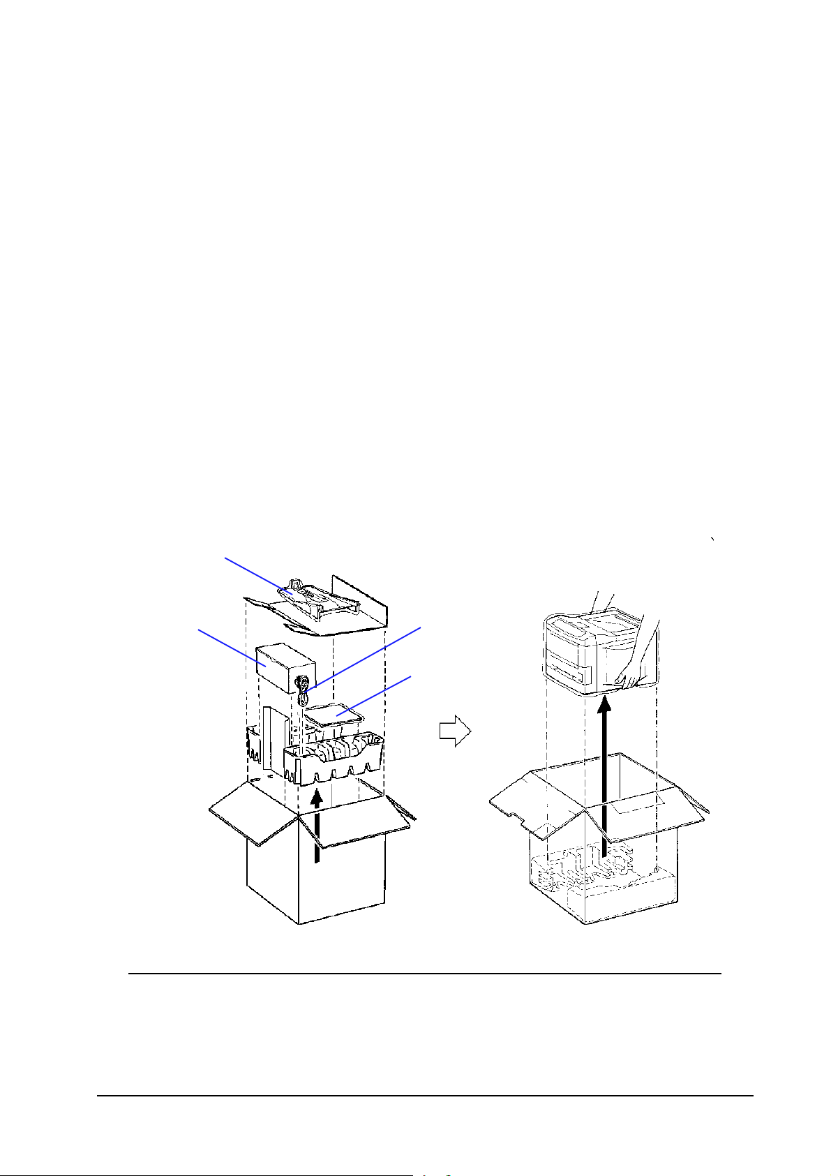
Unpacking
While unpacking the printer, check th at the listed parts are all present.
(A)
(B)
(C)
(D)
(A)
Face-up output tray (FS-3750 only)
(B)
Toner container tray (Box for the developer unit)
(C)
Power cord
(D)
User’s Manual and Kyocera Digital Library (CD-ROM), including the printer drivers and manuals.
2-3
FS-1750/FS-3750 Series
Page 4
Installation and operation
Unpacking and Inspection
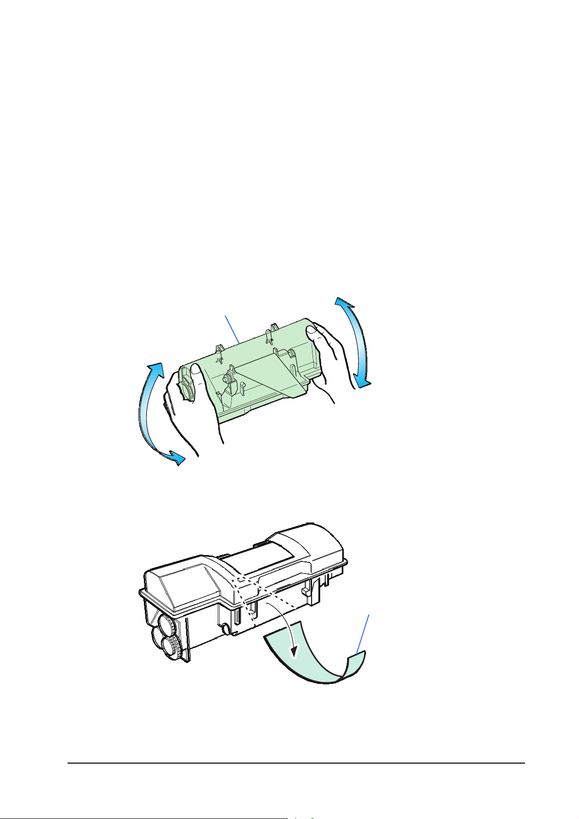
Installing toner
Take the toner container ➊ from the toner kit (TK-20/TK-20H) supplied with the printer. Give it a
good shake (5 to 6 times).
➊
Peel off the seal ➋ on the bottom of the toner container by carefully pulling off.
➋
2-4
FS-1750/FS-3750 Series
Page 5
Installation and operation
Unpacking and Inspection
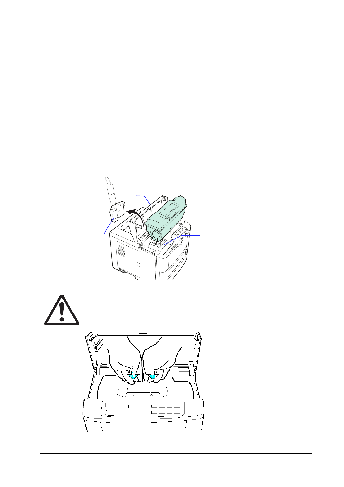
Open the top cover ➌ and remove the pad • , Insert the toner container into the printer as below.
Align the two locating pins at the bottom of the container with the mating
holes in the printer (the developer unit ➎).
➌
➊
➍
Caution - To avoid trouble (toner spilling, etc.), the toner container must be
correctly seated and locked in the printer. To do this, press the far side of
the container
➊
at the
PUSH HERE
marks until a click is heard.
➎
2-5
FS-1750/FS-3750 Series
Page 6
Installation and operation
Unpacking and Inspection
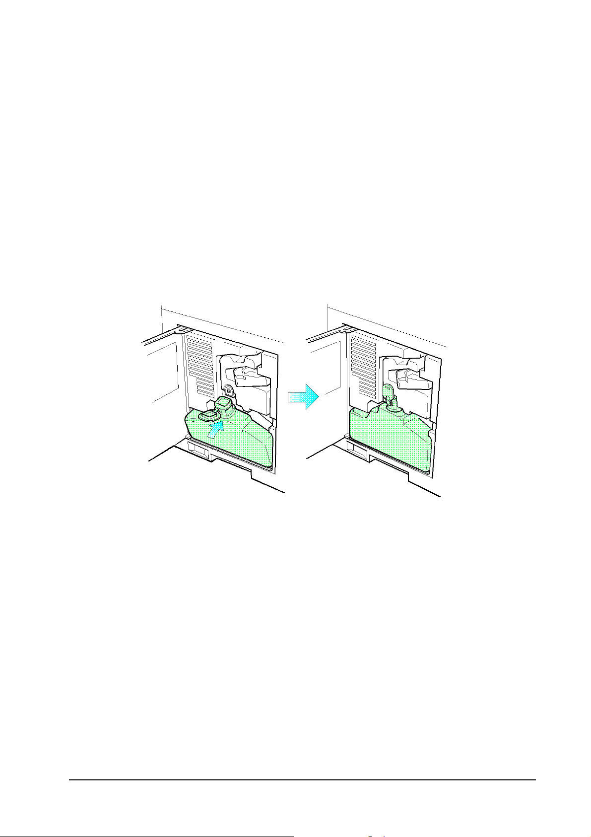
Installing the waste toner bottle
The waste toner bottle ➏ is also supplied. It must be installed inside the drum access door ➐ in the
left side of the printer. Open the drum access door and install it as shown.
➐
Developer initialization
The printer is shipped from the factory with no toner supplied in its developer unit. When the
printer is first switched on after the toner container is installed in the manner above, there will be a
delay of several minutes before the printer gets ready to print a job.
This delay is necessary for the printer to fill the developer reservoir with a sufficient amount of
toner to continuously support a print job.
The period of time for this delay varies depending on model: approximately 4 minutes for model
FS-1750 (14-ppm); and approximately 5 minutes for model FS-3750 (18-ppm).
Since the automatic implementation of the developer initialization is done only once at first
switching power on, if a new developer is in stalled in the printer, the developer must be in itialized
manually using the service mode on the front panel. Refer to the section
the new developer
➏
on page 3-12.
➏
Feeding toner into
2-6
FS-1750/FS-3750 Series
Page 7

Expanding memory
Expanded printer memory enables to print more complex pages, download more fonts, and define
more macros.
It begins by explaining how to remove the main circuit board from the printer, and explains how
to install a SIMM (single in-line memory module) on the main circuit board. The minimum
memory requirements for the printer with v arious options installed are listed in the table below.
Refer to this table for obtaining a rough approximation on how much memory is required for a
particular need.
Installation and operation
Expanding memory
Minimum memory requirements
Resolution
Printing environment 300 dpi 600 dpi
HP emulation 8MB 8MB 8MB 8MB
HP+duplex 8MB 8MB 8MB 12MB
HP+KPDL2 8MB 8MB 8MB 8MB
HP+KPDL2+duplex 8MB 8MB 12MB 12MB
HP+KPDL2+resource protection — 10MB 10MB 10MB
HP+KPDL2+resource protection+duplex — 14MB 14MB 14MB
1200 dpi
Fast mode Fine mode
SIMM to be used
Memory size in MB
Number of pins
Access speed
Parity
Bus width
4, 8, 16, 32
72
80 ns or faster
With/without
32 bits
2-7
FS-1750/FS-3750 Series
Page 8

Notes on handling the main circuit board and SIMMs
Protect the electronics by taking these precautions:
Installation and operation
Expanding memory
r
to discharge yourself of static electricity. While doing the work, it is recommended that you wear
an antistatic wrist strap.
r
r
Removing the main circuit board
The main circuit board of the printer is equipped with two sockets for memory expansion.
Expansion memory is available in the form of a SIMM.
Turn the printer’s power off. Unplug the printer’s power cable and
disconnect the printer from the computer or the network.
Before touching the main circuit board, touch a water pipe or other large metal object
Touch the main circuit board and
Follow the instructions the
SIMM
only by the edges.
SIMM
manufacturer provides.
2-8
FS-1750/FS-3750 Series
Page 9

Installation and operation
Expanding memory
Remove the PC card that may be inserted in the PC card slot at the left side of the printer.
Turn the power switch ➏ off. Remove the main circuit board ➐ by removing the three (plated)
screws ➑ from the rear cover.
“’
‘
Power OFF (O)
Pull the main circuit board all the way out of th e printer.
Caution - Before pulling the board out, clean an area on the table, etc., at
the back of the printer’s rear panel. Foreign objects, accidentally sticking to
the back of the main board, can cause serious damage to the printer.
Locate the sockets for memory expansion on the main board. These sockets have 72 pins and are
symbolized as YS02 and YS03.
2-9
FS-1750/FS-3750 Series
Page 10

Installation and operation
Expanding memory
SIMM sockets
2-10
FS-1750/FS-3750 Series
Page 11

Installation and operation
Expanding memory
Installing SIMMs
Insert the SIMM ➊ into the socket ➋ as shown. Carefully push the b oard upright until it snaps into
place. Make sure that the catches at the ends of the socket fit into the holes ➌ at the ends of the
SIMM board.
➊
➌
Catch
Catch
➋
2-11
FS-1750/FS-3750 Series
Page 12

Installation and operation
Expanding memory
Testing the expansion memory
After installing SIMMs in the printer, test the prin ter to see if the installation has been successful.
To test the expansion memory, turn printer power on and print a status page.
If the installation has been successful, the Total memory (Memory Allocation) of the status page
will show the expanded memory size corresponding to the amount of memory added.
2-12
FS-1750/FS-3750 Series
Page 13

Using the Control Panel
Installation and operation
Using the Control Panel
The printer’s control panel have LED indicators and a quartz message display to provide a quick
access to the printer’s conditions.
Indicators
➋
➌
➍
Indicator Status Function
ONLINE/Green
DATA/Green
ATTENTION/Red
Manual feed indicator/
Face-down stack indicator/
Face-up stack indicator/
➊
➌
➊
➎
Flashing A me mory error (See chapter 6) has oc curred.
Steady The printer is on-line and ready prints received data.
Off The printer is off-line. The printer stores but not print received data.
Flashing The printer is receiving data at its interface.
Steady Indicates either that data is being processed, or that data is being written
Flashing A service call is required. Read the message on the message display.
Steady The printer needs attention for a problem that can be cleared by the user.
➋
to the memory card.
(Also, see chapter 6.)
Lights when paper is fed from the multi-purpose feed tray, bulk (front
loading) feeder, or the option envelope feeder if installed. If this flashes,
paper jam is suggested in a particular location, refer to chapter 6.
Lights when printed pages are delivered to the face-down output tray. If
this flashes, paper jam is suggested in a particular location, refer to
chapter 6.
Lights when printed pages are delivered to the face-up output tray, or to
the option stacker if installed. If this flashes, paper jam is suggested in a
particular location, refer to chapter 6.
2-13
FS-1750/FS-3750 Series
Page 14

Installation and operation
Using the Control Panel
Cassette feed indicator/
Toner indicator/
•
•
Flashing: indicates the possibility that paper may be jammed at this
point, open and remove any jammed paper.
Lit: indicates when paper is fed from the paper feed cassette.
Flashes when the toner supply is low to request replenishing.
2-14
FS-1750/FS-3750 Series
Page 15

Front panel keys
Installation and operation
Using the Control Panel
Key Function
ONLINE
CONTINUE
STACK
FORM FEED
CANCEL
MODE/EXIT
FEED
STATUS/ENTER
Switches the printer on-line and off-line.
Depending on the message being indicated, there are cases where operation will
continue after pressing this key. If such a message is displayed, operation will
be resumed after pressing this key.
Selects whether printed pages are delivered to the face-down, face-up tray, or
optional sorter/stacker (if installed).
Prints and feeds out one page.
Abandons a printing job, resets numeric values, or cancels a setting procedure.
Enters/exits the mode selection menu. See
Selects the cassette feed or multi purpose tray feed.
Prints a page of information on the printer’s current status. (The printer must be
on-line.).
Mode selection menu
below.
Mode selection menu
The
MODE
key on the control panel allows to set or change the printer environment such as the
number of copies to make, emulation, etc., and to print a font list, manipulating a memory card,
etc.
During operating in the mode selection, several front panel keys serve exclusively for its
secondary function as labeled beside them (
EXIT, +, -, ENTER
, 3,4). The diagram on the next
page gives a full load map to the full options and the sequence of mode selection as well as usage
of these secondary keys.
2-15
FS-1750/FS-3750 Series
Page 16

Mode Select Menu
Installation and operation
Using the Control Panel
Ready
PAR 600 A4 001
Print
Menu map
Interface >
Parallel
Interface >
Serial
Interface >
Option
>Parallel I/F
Nibble (high)
>Parallel I/F
Auto
>Parallel I/F
High Speed
>Parallel I/F
Normal
>Baud rate
9600
>Data bits
8
>Stop bits
1
>Parity
None
>Protocol
DTR (pos.)&XON
>NetWare
Off
>NetWare >
On
>TPC/IP
Off
>NetWare >
On
>Ether Talk
Off
These items willl not show unless the printer is
installed with the applicable option unit/kit.
Basic Operations During Mode Selection
This diagram gives quick reference to all menu options and their
sequence of selection. For details, see printer’s User’s Manual.
key to enter Mode Selction mode.
Press the
1.
1.
1.1.
Press the
2.
2.
2.2.
cates the desired item.
Press the
3.
3.
3.3.
return.
Press the
4.
4.
4.4.
and the current setting can be changed.
5.
5. Press the
5.5.
Press the
6.
6.
6.6.
If you want to re-enter a setting, press the
pressing the
Press the
7.
7.
7.7.
>>NetWare Frame
Auto
>>DHCP
OFF
>>IP Address
MODE
or–key repeatedly until the message display indi-
+
key to move to a submenu. Press the key to
key once the desired menu appears.?will flash,
ENTER
and–key to select the desired setting.
+
key.
ENTER
key.
ENTER
key. This will enable currently selected settings.
EXIT
CANCEL
key before
Emulation >
PCL 6
Emulation >
KPDL
Emulation >
KPDL (AUTO)
Emulation >
IBM Proprinter
Emulation
Line Printer
Emulation >
DIABLO 630
Emulation >
EPSON LQ-850
>OPT. StatusPage
Off
>Code set
ISO-6 ASCII
>Print KPDL errs
Off
>Print KPDL errs
On
>Alt. Emulation
PCL 6
>Print KPDL errs
Off
>Print KPDL errs
On
>Code set
IBM US
>Code set
DIABLO US
>Code set
LQ US
>>Gateway
>>Subnet Mask
(*1)
(*2)
(*2)
Continued on next page
2-16
FS-1750/FS-3750 Series
Page 17

Continued from Previous page
Installation and operation
Using the Control Panel
Font
Internal
Font
Option
Page set >
Print quality >
> I000
>Courier
Dark
>Courier
Regular
>Letter Gothic
Regular
>Letter Gothic
Dark
>Size
012.00 point (s)
>Pitch
10.00 cpi
>List of Fonts
>Copies
001
>Orientation
Portrait
>Orientation
Landscape
>Page protect
Auto
>Page protect
On
>LF action
LF only
>LF action
CR and LF
>LF action
Ignore LF
>CR action
CR only
>CR action
CR and LF
>CR action
Ignore CR
>Wide A4
Off
>Wide A4
On
>KIR mode
On
>KIR mode
Off
>Ecoprint mode
Off
>Ecoprint mode
On
>Resolution
Fast 1200 mode
>Resolution
Fine 1200 mode
>Resolution
600 dpi
>Resolution
300 dpi
>Print density
03
>Read dataOpt. ROM >
>List of partitions
(*3)
(*3)
(*4)
(*5)
(*6)
(*7)
RAM DISK mode
Off
RAM DISK mode >
On
Continued on next page
(*8)
>RAM DISK size
>Write data
2-17
FS-1750/FS-3750 Series
Page 18

Continued from Previous page
Installation and operation
Using the Control Panel
>Read fontsMEMORY CARD >
>Format
>Read data
>Write data
>Delete data
>List of Partitions
Paper handling >
>MP tray mode
First
>MP tray size
A4or Letter
>MP tray type
Plain
>EF size
DLor Business
>EF type
Plain
>BulkFeeder size
>BulkFeeder type
Plain
>Cassette size >
>Cassette type
Plain
>Duplex mode
None
>>Unit
mm
>>Unit
inch
>>X dimension
>>Y dimension
(*9)
Continued on next page
>Sorter mode
Sorter
>Override A4/LT
Off
>Override A4/LT
On
>Type adjust >
Custom 1
>Reset type
adjust
(*10)
2-18
>>Manual elevate
>>Paper weight
Normal
>>Paper weight
Heavy (Thick)
>Duplex path
Disable
>Duplex path
Enable
(*11)
FS-1750/FS-3750 Series
Page 19

Continued from Previous page
Installation and operation
Using the Control Panel
Others >
s
>MSG language
English
>Form Feed
Time Out 030 sec.
>Sleep timer
030 min.
>Print HEX-DUMP
>Printer Reset
>Number of pages
printed 0123456
>Resource prot.
Off
>Resource prot.
Permanent
>Resource prot.
Perm / Temp
>Buzzer
On
>Buzzer
Off
>Service >
(*12)
(*13)
>>Print
Status Page
(*14)
Depending on the emulation selected, the f ollowing set
*1:
>Code sets
The printer can be set to print error data during KPDL emula-
*2:
tion. If this is set to
occurs during printing. This is set to
factory.
You can select either Courier or Letter Gothic. Any font can
*3:
be selected as
played when the Font menu is Internal.
The
*4:
>Size
ter-Gothic fonts. The
for these fixed width fonts.
Although
*5:
not usually appear, page protection mode will be forcibly set
to on if a
error occurs due to insufficient printer memory. Be sure to
return this setting to
memory efficiency.
Tur n i n g
*6:
acters that can be printed in a line for an A4 page (78 characters at 10 pitch) and likewise increases the maximum per
line on Letter size paper (80 characters at 10 pitch).(Only PCL
6 emulation)
This sets the res olution for printing. For 1200 dpi there are
*7:
two modes. In Fast 1200 mode, printing is equal to 1200 dpi
(1200 dpi horizontal × 600 dpi vertical) comparatively, Fine
are available.
, error data will be printed if trouble
On
or
Dark
menu is not available for the Courier and Let-
Auto
Print overrun Press CONTINUE
increases the maximum number of char-
ON
Regular
>Pitch
is the default setting and this menu does
in order to maintain high printer
Auto
before leaving the
Off
. These fonts are dis-
menu is displayed instead
>>Developer
>>Drum
1200 mode is slower, but in Fine 1200 mode true1200 dpi
printing is facilitated. The printing is slower than Fast mode
but the print q uality is better.
This is displayed only after the FS-1750 memory has been
*8:
expanded. (The total must be 12 MB or more)
*9:
This is displayed when the size dial on the paper cassette is
set to Custom. (See printer’s User’s Manual.)
This sets whether to enable or disable the difference between
*10:
A4 size and letter size. Under the default setting of
paper size of the paper source is matched to the paper size
given for the data, and if these differ a corresponding error
message is displayed. When this is set to
formed even if the actual paper size differs from the paper
size given for the data.
This menu is displayed only when
*11:
After the printer accepts all data and there is no more data
*12:
from the computer, the printer will wait a set amount of time
without printing the final page. Once this preset amount of
time has elapsed, the printer will automatically issue a form
feed. This timeout setting can be set in 5-second increments
up to 495 seconds.
This is the total number of pages printed by the printer up to
*13:
the present time.
These menus are for service personnel.
*14:
They should not be operated by the user.
Custom #
, printing is per-
On
, the
Off
is selected.
2-19
FS-1750/FS-3750 Series
Page 20

Installation and operation
Using the Control Panel
Service mode
Within Others option, the Service mode can be accessed by authorized service personnel.
This mode provides two special treatments for service purpose: cleaning on the drum surface and
accelerating initial toner replenishment for a new develope r.
The service mode is available only when the pr inter is ready. While in service mode, the printer
accepts print data but does not print it.
For details, see chapter 3, page 3-13.
2-20
FS-1750/FS-3750 Series
 Loading...