

Page 1
Service Manual
LASER PRINTER
Ecosys FS-1200
Page 2

FS-1200 Service Manual
©Kyocera Corporation 1996—1999 All rights reserved. Export Edition
Conventions/Preface
Notice
The information in this manual is subject to
change without notification. Additional
pages may be inserted in future editions.
The user is asked to excuse any technical
inaccuracies or typographical errors in the
present edition.
No responsibility is assumed if accidents
occur while the user is following the
instructions in this manual. No
responsibility is assumed for defects in the
printer's firmware.
The contents of this manual are protected
by copyright. No part of this manual may
be reproduced or copied by any means
without the permission of the copyright
holder. The printer's firmware (contents of
its read-only memory) is similarly
protected by copyright.
Trademark Notice
PRESCRIBE is a registered trademark of
Kyocera Corporation. PRESCRIBE II,
KIR, Kyocera Image Refinement, and
Ecosys are trademarks of Kyocera
Corporation.
Diablo 630 is a product of Xerox
Corporation. IBM Proprinter X-24E is a
product of International Business Machine
Corporation. Epson LQ-850 is a product of
Seiko Epson Corporation. HP LaserJet IV,
5Si, 5M, and HP-7475A are product of
Hewlett-Packard Company. HewlettPackard, PCL, and HP-GL are registered
trademarks of Hewlett-Packard Company.
Centronics is a trade name of Centronics
Data Computer Corp.
PowerPC is a trademark of International
Business Machines Corporation.
EnergyStar is a U.S. registered mark.
This Kyocera page printer uses
PeerlessPrintXL to provide the HP LaserJet
compatible PCL6 language emulation.
PeerlessPrintXL is a trademark of The
Peerless Group, Redondo Beach, CA
90278, U.S.A.
This product was developed using the
TM
Tornado
Real Time Operating System
and Tools from Wind River Systems.
Contains UFST
TM
and MicroType® from
Agfa Corporation.
Warning:
This equipment has been certified to
comply with the limits for a Class B
computing device, pursuant to Subpart J of
Part 15 of FCC Rules. Only peripherals
(computer input/output devices, terminals,
etc.) certified to comply with the Class B
limits may be attached to this equipment.
Operation with non-certified peripherals is
likely to result in interference to radio and
TV reception.
Check that the cable is wired correctly. If
an IBM communication adapter cable type
1502067 is used, it will have to be
resoldered the wiring at the printer end of
the cable. The procedure is as follows.
ii
Page 3

Conventions
Throughout this manual, the following conventions are used:
Color is available when viewed online to emphasize important items.
CAPITAL letters are used to name printer parts and assemblies.
Conventions/Preface
Italic letters refer related chapters or sections or documentations.
Bold letters are also used for emphasis wherever italics may cause a confuse.
This symbol followed by
which, if ignored, could result in personal injury, and/or irrevocable damage to the printer.
When followed by
precautions which, if ignored, could result in damage to the printer.
Warning
Caution
denotes that the following paragraph(s) includes precautions
this symbol denotes that the following paragraph(s) include the
iii
Page 4

About the chapters ...
Unless otherwise specified, the contents of this manual apply to all printer models of Ecosys FS-
1200.
The manual is comprised of the followin g chapters:
Conventions/Preface
Chapter Contents
One - Product information Includes printer specifications, product appearances, safety
Two - Installation and operation Provides how to install and operate the printer.
Three - Maintenance Instructs maintenance to be conducted periodically on the printer.
Four - Operation overview Explains basic functions of the printer methcnism including engine
Five - Disassembly Instructs removal of parts for replacing them.
Six - Troubleshooting Provides countermesure to follow for troubleshooting.
Appendix Contents
A - Printer interface Information regarding the printer’s parallel and serial (Optional)
B - Status page Explains detail of the service information on the status page.
C - Paper specifications Explains how to choose the right paper.
Separate Contents
Parts catalog Information o f parts for ordering.
The manual will be supplemented with chapters or appendixes accordingly.
information, etc.
and logic controller systems.
interfaces.
iv
Page 5

Conventions/Preface
REVISION HISTORY
Version Date Replaced pages Remarks
1.00 1-Oct-99 -
This document was created using Microsoft® Word 95. To obtain its intended view of the
document, the following fonts must be installed in addition to those already installed under
Windows 95 by default: Century Schoolbook (regular/italic/bold), Humanist 777
(regular/italic), and Humanist 777 Black (black).
VISIT US AT OUR INTERNET HOME PAGE:
http://www.kyocera.com
v
Page 6

Conventions/Preface
vi
Page 7

Chapter One PRODUCT INFORMATION
Page 8

Chapter One
Printer identification labeling 1-3
Printer Specifications 1-4
Recommended flash cards 1-7
Front and rear views 1-8
Front view (FS-1700/3700) 1-8
Paper feed unit 1-9
Internal assemblies ➊ 1-10
Internal assemblies ➋ 1-11
Safety information 1-12
Laser safety 1-12
Laser notice 1-12
CDRH regulations 1-13
Ozone concentration 1-13
FCC notice 1-13
Important note on the interface connectors 1-15
Canadian Department of Communications compliance statement 1-16
Avis de conformité aux normes du ministère des Communications du Canada 1-16
ISO 7779 1-16
Environmental requirements 1-17
Environmental conditions 1-17
Clearance 1-19
Places to avoid 1-20
Note on power 1-21
CONTENTS 1
About the toner 1-23
Toner container handling 1-23
Toner storage 1-24
Page 9
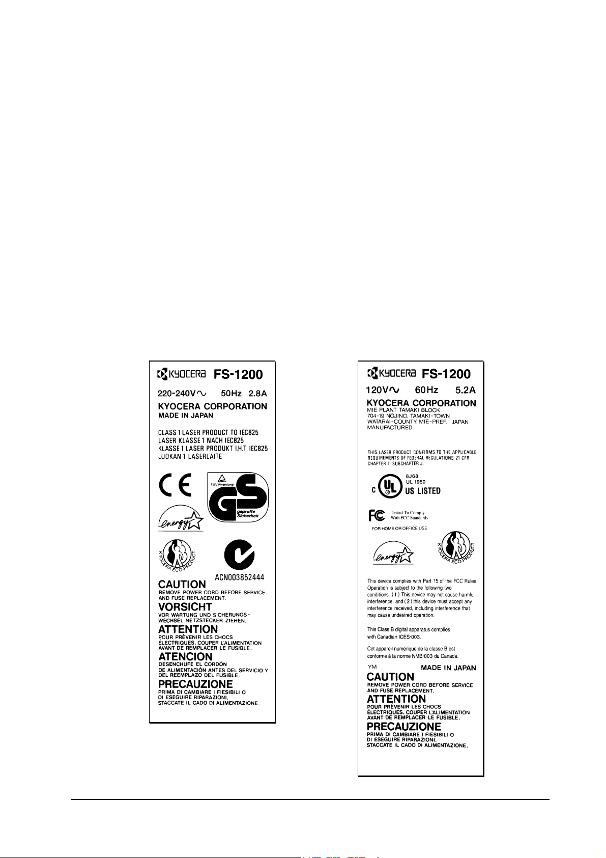
Printer identification labeling
The printer bears its model and serial numbers at its back.
The label also contains other safety precautions.
Product information
Printer identification labeling
Europe/Asia version
US/Canada version
1-3
FS-1200
Page 10

Printer Specifications
ENGINE
Specification
Product information
Printer Specifications
Print method Electrophotography laser scan
Print speed (A4 or letter, when printing
multiple copies of the same page)
Resolution (dpi) 600 horizontal/600 vertical
Smoothing KIR 2 (2400 horizontal/600 vertical)
First print (A4 or letter), depends on
input data
Warm-up time at 23°C or 68°F 55 seconds or less
Maximum duty cycle 20,000 pages/month
Laser diode Visible laser
Main charger Scorotron wire
Transferring Biased roller
Separation Charging
Drum cleaning Blade
Drum discharging LED array
Fuser Heat and pressure
Paper Plain paper (See
Capacity of paper feed tray 250 sheets
Capacity of output trays 250 sheets
12 pages/minute
15 seconds or less
Appendix B
)
1-4
FS-1200
Page 11

CONTROLLER
Specification
CPU Power PC 71MHz RISC Proccesor
System ROM size 4MB (16 Mb×2)
Resident font ROM size 4MB (32 Mb×1)
Option fonts ROM 16Mbits (PK-4)
Main RAM 4MB (2 MB×2)
Additional RAM (SIMM) 64MB maximum
Memory card SRAM or flash, JEIDA 4.2/PCMCIA 2.1
Recommended flash cards
See
in this chapter.
Product information
Printer Specifications
Host interface Parallel/option
Page description language Prescribe II
Standard emulation modes HP LaserJet 5M, HP LaserJet 5Si, IBM
WEIGHT AND DIMENSIONS
Specification
Width 37.3 cm (14.7”)
Height 31 cm (12.2”)
Depth 38.3 cm (15.1”)
Weight (Main unit) 14.3 kg (30 lb.)
Proprinter X24E, Diablo 630, Epson LQ850, line printer
1-5
FS-1200
Page 12

POWER REQUIRMENTS
Specification
Voltage requirements US/Canada 120V AC ±10%, 60Hz ±2%
Europe/Asia 220-240V AC±10%, 50 or 60Hz ±2%
Watts Maximum 580 W
Printing 311 W
Standby 105 W
Sleeping 16 W
Maximum current US/Canada 5 A
Europe 2.8 A
Product information
Printer Specifications
ENVIRONMENTAL REQUIREMENTS
Specification
Operating temperature and humidity
Maximum altitude 2,000 m (6,500 feet)
Noise emission 50 dB maximum/39 dB at standby
10°C to 32.5°C (50°F to 90.5°F), 20
to 80% RH
1-6
FS-1200
Page 13

Product information
Printer Specifications
Recommended flash cards
FS-1200 Series printers provide support for a JEIDA/PCMCIA category of memory card in both
SRAM and flash types.
Following is a list of makes and models of flash cards recommended for use with the printers.
Note that the flash card to be used should be operable on 5V
DC
.
Model Capacity
AMD AmC001CFLKA 1 MB
AmC002CFLKA 2 MB
AmC004CFLKA 4 MB
AmC004DFLKA 4 MB
AmC008DFLKA 8 MB
AmC010CFLKA 10 MB
Fujitsu MB98A81063 1 MB
MB98A81183 2 MB
MB98A81273 4 MB
MB98A81373 8 MB
MB98A81473 16 MB
Panasonic BN-02MHF4C (CC) 2 MB
BN-04MHF4C (CC) 4 MB
Intel Series 2+/iMC004FLSP 4 MB
Centennial FL01M-20-11114-03 1 MB
FL02M-20-11114-03 2 MB
1-7
FS-1200
Page 14

Front and internal views
Front view
Product information
Front and internal views
Paper exit roller
Power switch
Waste
toner/drum
access door
Front operator
panel
Paper feed unit
release lever
Paper cassette
1-8
Paper size indicator
FS-1200
Page 15

Paper feed unit
Product information
Front and internal views
Paper size
indicator
Maulti-purpose
tray
Paper feed unit
Paper feed unit
release lever
1-9
Memory card slot
FS-1200
Page 16
Product information
Front and internal views
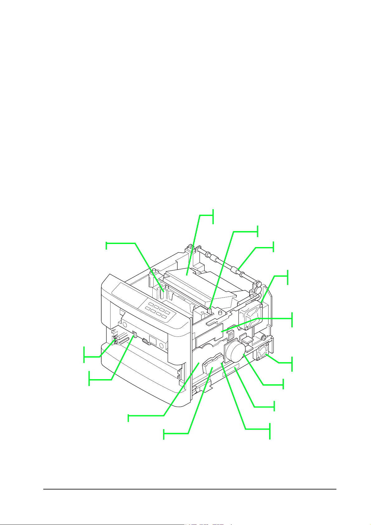
Internal assemblies
Developer unit
➊
Laser scanner
assembly
Toner container release lever
Paper exit roller
Upper frame
venti fan
Relay board
KP-504
Cassette paper
size switches
Manual feed
actuator
Drive assembly
Feed roller clutch
1-10
Controller venti
fan
Main motor
Memory card slot
Registration
roller clutch
FS-1200
Page 17
Product information
Front and internal views
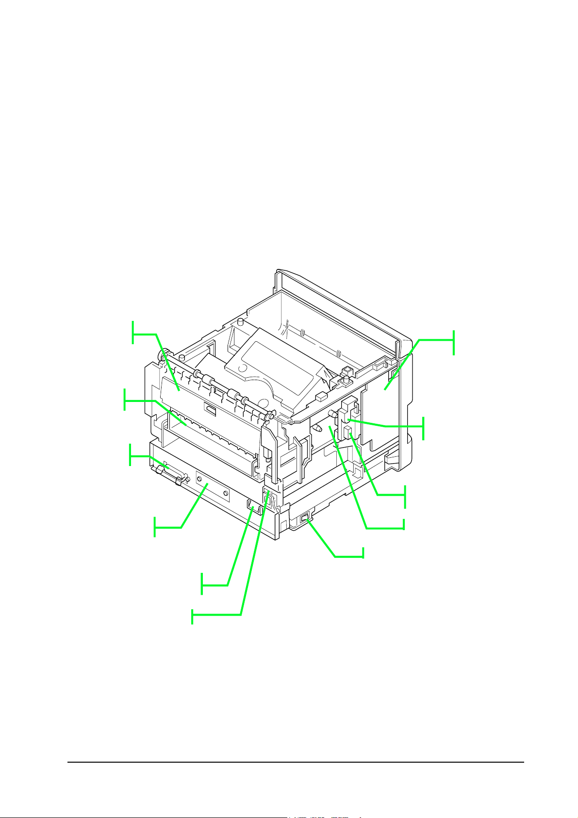
Internal assemblies
Rear paper
jam access
Face-up
paper
Parallel
interface
Option
➋
High voltage
board
Main charger
terminal
Drum connector
YC821
Face-up stacker
connector
AC inlet
1-11
FS-1200
Page 18

Product information
Front and internal views
Safety information
Laser safety
This printer is certified as a Class 1 laser product under the U.S. Department of Health and Human
Services (
Safety Act of 1968. This means that the printer does not produce hazardous laser radiation. Since
radiation emitted inside the printer is completely confined within protective housings and external
covers, the laser beam cannot escape from the printer during any phase of user operation.
) Radiation Performance Standard according to Radiation Control for Health and
DHHS
Laser notice
The printer is certified in the U.S. to conform to the requirements of
DHHS
21
Subchapter for
CFR
Class I (1) laser products, and elsewhere is certified as a Class I laser product conforming to the
requirements of
IEC
825.
Class I laser products are not considered to be hazardous. The printer contains internally a Class
IIIb (3b) laser that is nominally a 5 milliwatt laser operating in the wavelength region of 780
nanometers. The laser system and printer are designed so there is never any human access to laser
radiation above a Class I level during normal operation, user maintenance, or prescribed service
condition.
Laser product labels are located on top of the laser scanner:
Laser scanner
1-12
FS-1200
Page 19

Product information
Front and internal views
Warning - Use of controls or adjustments or performance of procedures
other than those specified herein may result in hazardous radiation
exposure.
CDRH regulations
The Center of Devices and Radiological Health (
) of the U.S. Food and Drug Administration
CDRH
implemented regulations for laser products on August 2, 1976. These regulations apply to laser
products manufactured after August 1, 1976. Compliance is mandatory for products marketed in
the United States. A label indicating compliance with the
regulations must be attached to
CDRH
laser products marketed in the United States.
Ozone concentration
Laser printers generate ozone gas (O
) which may concentrate in the place of installation and
3
cause an unpleasant smell. To minimize the concentration of ozone gas, we recommend that the
laser printer not be installed in a confined area lacking ventilation.
FCC notice
This device complies with Part 15 of the
Rules. Operation is subject to the following two
FCC
conditions: (1) This device may not cause harmful interference, and (2) this device must accept
any interference received, including interference that may cause undesired operation.
This equipment has been tested and found to comply with the limits for a Class B digital device,
pursuant to Part 15 of the
Rules. These limits are designed to provide reasonable protection
FCC
against harmful interference in a residential installation. Th is equipment generates, uses, and can
radiate radio frequency energy and, if not installed and used in accordance with the instructions,
may cause harmful interference to radio communication. However, there is no guarantee that
interference will not occur in a particular installation.
If this equipment does cause harmful interference to radio or television reception, which can be
determined by turning the equipment off and on, the user is encouraged to try to correct the
interference by one or more of the following measures:
1-13
FS-1200
Page 20

Product information
Front and internal views
-
Reorient or relocate the receiving antenna.
-
Increase the separation between the equipment and receiver.
-
Connect the equipment into an ou tlet o n a circuit different from that to which the
receiver is connected.
-
Consult the dealer or an experienced radio/
technician for help.
TV
Change or modifications not expressly approved by the manufacturer for compliance could void
the user’s authority to operate the equipm en t.
Interference cable to the computer shall be used with shielded circular cable.
Any modification without prior permission may cause harmful interface. If any
modification/change is introduced to this equipment without prior permission, Kyocera, as the
manufacturer, cannot guarantee compliance with
To use equipment which does not comply with
rules.
FCC
rules is prohibited. The printer may be
FCC
optionally installed with the follo wing units:
CONFORMING TO CLASS B LIMITS:
•
-20 Duplexer/DU-21
DU
-20 Paper Handler/Stacker
•
HS
-20 Paper Feeder/PF-21
•
PF
-20mini Paper Feeder/PF-21mini
•
PF
-6 Sorter/Stacker
•
SO
-20 Bulk Paper Stacker
•
ST
-3 AppleTalk Interface Board
•
IB
1-14
FS-1200
Page 21

Product information
Front and internal views
Important note on the interface connectors
Be sure to turn off printer power before connecting or disconnecting an interface cable to the
printer. For protection against static discharge which may be applied to the printer's internal
electronics through the interface connector(s), keep any interface connector which is not in use
capped using the protective cap supplied.
Warning - This equipment has been certified to comply with the limits for
a Class B computing device, pursuant to Subpart J of Part 15 of FCC Rules.
Only peripherals (computer input/output devices, terminals, etc.) certified
to comply with the Class B limits may be attached to this equipment.
Operation with non-certified peripherals is likely to result in interference
to radio and TV reception.
1-15
FS-1200
Page 22

Product information
Front and internal views
Canadian Department of Communications compliance statement
This Class B digital apparatus complies with Canadian ICES-003.
Avis de conformité aux normes du ministère des Communications du
Canada
Cet appareil numérique de la classe B est conforme á la norme NMB-003 du Canada.
ISO 7779
Maschinenlärminformationsverordnung 3.
beträgt 70 dB(A) oder weniger gemäß
ISO
, 18.01.1991: Der höchste Schalldruckpegel
GSGV
7779.
1-16
FS-1200
Page 23

Environmental requirements
Environmental conditions
Product information
Environmental requirements
The
ENVIRONMENTAL REQUIREMENTS
optimum operation of the printer. The use of the printer in a location which does not satisfy the
requirements may result in troubles and risk shortening its service life.
The printer will work best if it is installed in a location that is:
r
Level and well supported (Place the printer on a sturdy table or desk.)
r
Not exposed to sunlight or other bright light (not next to an uncurtained window). Do not
place the printer on an unstable cart, stand, or table.
r
Near an
wall outlet, preferably one that can be used for the printer alone (See section
AC
section on page 1-6 should be observed to ensure the
1-17
FS-1200
Page 24

Product information
Environmental requirements
POWER REQUIRMENTS
on page 1-6). (The outlet should have a ground slot, or an adaptor
should be used. If you use an extension cord, the total length of the power cord plus extension
cord should be 17 feet or 5 meters or less.
r
Well ventilated, not too hot or cold, an d not too damp or dry (See section
REQUIREMENTS
on page 1-6). If you install the printer where the temperature or humidity is
ENVIRONMENTAL
outside the requirements in section Environmental requirements in chapter 1, the best print
quality may not be expected and there will be an increased chance of paper jams.
r
Provide a sufficient clearances around the printer to ensure ventilation and ease of access. See
section
Clearance
on page 1-19.)
1-18
FS-1200
Page 25

Product information
Environmental requirements
Clearance
Allow the necesary minimum clearance on all sides of the printer (below). A total space of 92 by
138 cm (36 by 54”) is needed.
➎
➊
➋
Clearance Dimensions
➊
Left
Front
Right
Back
Above
➋
➌
➍
➎
30 cm (12”)
60 cm (24”)
25 cm (10”)
40 cm (16”) or 20 cm (8”) if optional the face-up tray
is not installed.
30 cm (12”)
➍
➌
1-19
FS-1200
Page 26

Environmental requirements
Places to avoid
Avoid installing the printer in locations exposed to:
• Direct drafts of hot or cold air.
• Direct drafts of outside air. (Avoid locations next to outside doors.)
Product information
• Sudden temperature or humidity changes.
• Any source of high heat, such as a radiator or stove.
• Excessive dust. Dust and smoke may cause contamination on the laser scanner window,
causing print quality problem.
• Vibration.
• Ammonia fumes or other harmful fumes. (In case of humigating the room or saturate it with
insecticide, remove the printer first.)
• Avoid greenhouse-like rooms. (Because of sunlight and humidity.)
• Avoid enclosed spaces that block v e ntilation.
• Avoid sites more than 6500 feet or 2000 meters above sea level.
1-20
FS-1200
Page 27

Product information
Environmental requirements
Note on power
• Use only the power source voltage conforming to the printer’s rated power voltage (See the
1-21
FS-1200
Page 28

Product information
Environmental requirements
POWER REQUIRMENTS
• Disconnect the printer from the power source before attempting removal or re-placement of an
electrical component or a printed-circuit board.
• The printer should not be connected to a power source until the instruction is given to do so
when performing tests described in this manual.
• In connecting the printer power, exercise an extreme care in handling the power supply or any
other electric parts which may give an electric shock.
• Before performing maintenance or repair, power from both the power source and the
associated peripheral devices (computer, sorter, etc.) should be disconnected, unless otherwise
specified.
• To avoid possible electrical shock, extreme caution must be exercised in handling the power
cord and any other electrical part.
Warning!
Warning! /Wornung!
Warning!Warning!
on page 1-6). Do not use other power sources.
As the disconnect device is not incorporated in the printer's AC primary circuit, an easily
accessible socket outlet must be provided near the equipment.
If the printer is used with the optional Sorter (SO-6) or Stacker (ST-20), in order to avoid shortcircuiting, it should be ensured that these devices are plugged securely into their respective power
outlets.
Da kein Trennschalter in den Wechselstrom-Primärkreis des Druckers eingebaut ist, muß eine
leicht zugängliche Steckdose in der Nähe des Gerätes vorhanden sein.
Wenn der Drucker mit dem gesonderten Sorter (SO-6) oder Stapler (ST-20) verwendet wird, muß
darauf geachtet werden, daß diese Geräte einwandfrei an separate Steckdosen angeschlossen sind,
um Kurzschluß zu vermeiden.
1-22
FS-1200
Page 29

About the toner
The printer should use Kyocera TK-25 Toner Kit. To ensure the high print quality and long service
life, the following handling precautions should apply.
Caution - As the Ecosys printers are designed to ensure the optimum print
quality when used with the Kyocera’s proprietary toner, Kyocera do not
recommend to use any refilled toner containers that may be available
commercially. This is because Kyocera have no means for control over how
such refilled toner could affect the print quality and the reliability of the
printer.
Product information
About the toner
Toner container handling
To loosen and mix the toner inside, with the label side down, thoroughly shake the toner container
(in the direction of the arrow) ten times or more.
Do not attempt to disassemble or refill the toner container.
1-23
FS-1200
Page 30

Product information
About the toner
Toner storage
The toner contained in the container is susceptible to temperature and humidity. To ensure the
high print quality, store the toner container in a place that satisfy the following environ mental
conditions:
Note.
Temperature -20°C to 40°C (-4°F to 104°F)
Humidity 15 to 90% RH
If the toner container is removed from the printer’s developer unit, put it in a protective bag and
keep it in a dark place.
Caution -
Caution - If the printer is shipped for return, etc., do not ship it with the
Caution - Caution toner container installed. Otherwise, toner may leak and contamination
may result in the printer.
1-24
FS-1200
Page 31

Product information
About the toner
1-25
FS-1200
Page 32

Chapter Two INSTALLATION/OPERATION
Page 33

Chapter Two
Unpacking and Inspection 2-3
Unpacking 2-3
Installing toner 2-4
Installing the waste toner bottle 2-6
Developer initialization 2-6
Loading paper 2-7
Expanding memory 2-8
Minimum memory requirements 2-8
SIMM to be used 2-8
Notes on handling the main circuit board and SIMMs 2-9
Removing the main circuit board 2-9
Installing SIMMs 2-11
Testing the expansion memory 2-13
Using the Control Panel 2-14
Indicators 2-14
Front panel keys 2-15
Mode selection menu 2-15
Service mode 2-19
CONTENTS
Page 34

Unpacking and Inspection
Examine the package for any signs of damage that may have been caused during shipping. If the
carton is found badly damaged, leave the carton unopened and immediately notify the carrier
before accepting it.
Installation and operation
Unpacking and Inspection
Unpacking
While unpacking the printer, check th at the listed parts are all present.
(D)
(C)
(B)
(E)
(A)
Printer
(A)
Waste tonar bottle
(D)
User’s Manual and Kyocera DigitalLibra (CD ROM), including the printer
drivers and manuals.
(B)
Tonar container
2-3
(C)
Power cord
(E)
Plastic bag for Developer Unit
FS-1200
Page 35

Installing toner
Installation and operation
Unpacking and Inspection
Take the toner container from the toner kit (
(5 to 6 times).
Peel off the seal ➋ on the bottom of the toner container by carefully pulling off.
-25) supplied with the printer. Give it a good shake
TK
2-4
•
FS-1200
Page 36

Installation and operation
Unpacking and Inspection
Insert the toner container in the printer as belo w.
developer unit ➌ as show in the figure.
Install the toner container
➊
on the
➊
➌
Caution - To avoid trouble (toner spilling, etc.), the toner container must
be correctly seated and locked in the printer. To do this, press the far side
of the container
➊
at the
PUSH HERE
marks until a click is heard.
2-5
FS-1200
Page 37

Installation and operation
Unpacking and Inspection
Installing the waste toner bottle
The waste toner bottle ➍ is also supplied. It must be installed inside the drum access door ➎ in the
left side of the printer. Open the drum access door and install it as shown.
➎
➍➍
Developer initialization
The printer is shipped from the factory with no toner supplied in its developer unit. When the
printer is first switched on after the toner container is installed in the manner above, there will be a
delay of several minutes before the printer gets ready to print a job.
This delay is necessary for the printer to fill the developer reservoir with a sufficient amount of
toner to continuously support a print job.
The period of time for this delay varies depending on model: approximately 7 minutes for model
-1200 (12-ppm).
FS
Since the automatic implementation of the developer initialization is done only once at first
switching power on, if a new developer is in stalled in the printer, the developer must be initialized
manually using the service mode on the front panel. Refer to the section
the new developer
on page 3-12.
Feeding toner into
2-6
FS-1200
Page 38

Loading paper
The paper cassette provided with the printer can accommodate paper sizes from A5 to legal, by
adjusting the position of the paper guides and the paper stopper. Paper sizes that are not standard
sizes (custom sizes) but within the size limitations can also be loaded into the cassette. When
loading custom sizes into the cassette, the size must be input into the printer on the control panel.
Installation and operation
Loading paper
Turn the paper size dial so that the size of the paper you are going to use appears in the paper size
window.
When the paper size dial is set to "Custom" th e paper size must be set into the printer o n the control panel.
Paper Size Dial
2-7
Paper Size Window
FS-1200
Page 39

Expanding memory
Expanded printer memory enables to print more complex pages, download more fonts, and define
more macros.
It begins by explaining how to remove the main circuit board from the printer, and explains how
to install a
requirements for the printer with various options installed are listed in the table below. Refer to
this table for obtaining a rough approximation on how much memory is required for a particular
need.
DIMM
Installation and operation
Expanding memory
(dual in-line memory module) on the main circuit board. The minimum memory
Minimum memory requirements
Resolution
Printing environment 300 dpi 600 dpi
HP emulation 4MB 4MB
HP+duplex 4MB 5MB
HP+KPDL 4MB 4MB
HP+KPDL+duplex 4MB 5MB
HP+KPDL+resource protection n/a 10MB
HP+KPDL+resource protection+duplex n/a 14MB
DIMM to be used
Memory size in MB
Number of pins
Bus width
8, 16, 32, 64
100(JEDEC
standard)
32 bits
Reference:
Guideline for SDRAM DIMM Support with Kyocera Ecosys Printers.
2-8
FS-1200
Page 40
Notes on handling the main circuit board and DIMM
Protect the electronics by taking these precautions:
Installation and operation
Expanding memory
r
Before touching the main circuit board, touch a water pipe or other large metal
object to discharge yourself of static electricity. While doing the work, it is
recommended that you wear an antistatic wrist strap.
r
r
Touch the main circuit board and
Follow the instructions the
DIMM
only by the edges.
DIMM
manufacturer provides.
Removing the main circuit board
The main circuit board of the printer is equipped with one socket for memory expansion.
Expansion memory is available in the form of a
DIMM
.
Turn the printer’s power off. Unplug the printer’s power cable and
disconnect the printer from the computer or the network.
2-9
FS-1200
Page 41

Installation and operation
Expanding memory
Remove the PC card that may be inserted in the PC card slot at the left side of the printer.
Turn the power switch ➏ off. Remove the main circuit board ➐ by removing the three (plated)
screws ➑ from the rear cover.
The diagram below examples model FS-1700 and FS-3700.
‘
Pull the main circuit board all the way out of th e printer.
Caution - Before pulling the board out, clean an area on the table, etc., at
the back of the printer’s rear panel. Foreign objects, accidentally sticking
to the back of the main board, can cause serious damage to the printer.
Refer to the diagram on page 2-11. Locate the sockets for memory expansion on the main board.
These sockets have 100 pins and are symbolized as YS102.
2-10
FS-1200
Page 42

Installation and operation
Expanding memory
DIMM sockets
Installing DIMM
Insert the DIMM into the socket as shown. Open the clips ➊ on both ends of the DIMM slot.
Insert the DIMM ➋ into the memory slot, so that the notches on the DIMM align with the
corresponding protusions in the slot. Close the clips ➋ DIMM slot to secure the DIMM ➊.
2-11
FS-1200
Page 43

•
Installation and operation
Expanding memory
Œ
Œ
2-12
FS-1200
Page 44

Testing the expansion memory
Installation and operation
Expanding memory
After installing
To test the expansion memory, turn printer power on and print a status page.
If the installation has been successful, the Total memory (Memory Allocation) of the status page
will show the expanded memory size corresponding to the amount of memory added.
in the printer, test the printer to see if the in stallation has been successful.
DIMM
2-13
FS-1200
Page 45

Using the Control Panel
Installation and operation
Using the Control Panel
The printer’s control panel have
access to the printer’s conditions.
Indicators
➋
➌
➎
➍
Indicator Status Function
ONLINE/Green
DATA/Green
ATTENTION/Red
Manual feed indicator/
Face-down stack indicator/
Face-up stack indicator/
Cassette feed indicator/
Toner indicator/
➊
➌
•
•
indicators and a quartz message display to provide a quick
LED
➊
Flashing A memory error (See chapter 6) has occurred.
Steady The printer is on-line and ready prints received data.
Off The printer is off-line. The printer stores but not print received data.
Flashing The printer is receiving data at its interface.
Steady Indicates either that data is being processed, or that data is being written
Flashing A service call is required. Read the message on the message display.
Steady The printer needs attention for a problem that can be cleared by the user.
➋
to the memory card.
(Also, see chapter 6.)
Lights when paper is fed from the multi-purpose feed tray, bulk (front
loading) feeder, or the option envelope feeder if installed. If this flashes,
paper jam is suggested in a particular location, refer to chapter 6.
Lights when printed pages are delivered to the face-down output
tray(optional). If this flashes, paper jam is suggested in a particular
location, refer to chapter 6.
Lights when printed pages are delivered to the face-up output tray, or to
the option stacker if installed. If this flashes, paper jam is suggested in a
particular location, refer to chapter 6.
Flashing: indicates the possibility that paper may be jammed at this
point, open and remove any jammed paper.
Lit: indicates when paper is fed from the paper feed cassette.
Flashes when the toner supply is low to request replenishing.
2-14
FS-1200
Page 46

Front panel keys
Installation and operation
Using the Control Panel
Key Function
ONLINE
CONTINUE
STACK
FORM FEED
CANCEL
MODE/EXIT
FEED
STATUS/ENTER
Switches the printer on-line and off-line.
Depending on the message being indicated, there are cases where operation will
continue after pressing this key. If such a message is displayed, operation will
be resumed after pressing this key.
Selects whether printed pages are delivered to the face-down, face-up tray, or
optional sorter/stacker (if installed).
Prints and feeds out one page.
Abandons a printing job, resets numeric values, or cancels a setting procedure.
Enters/exits the mode selection menu. See
Selects the cassette feed or multi purpose tray feed.
Prints a page of information on the printer’s current status. (The printer must be
on-line.).
Mode selection menu
below.
Mode selection menu
The
MODE
key on the control panel allows to set or change the printer environment such as the
number of copies to make, emulation, etc., and to print a font list, manipulating a memory card,
etc.
During operating in the mode selection, several front panel keys serve exclusively for its
secondary function as labeled beside them (
EXIT, +, -, ENTER
, 3,4). The diagram on the next
page gives a full load map to the full options and the sequence of mode selection as well as usage
of these secondary keys.
2-15
FS-1200
Page 47

Installation and operation
Using the Control Panel
2-16
FS-1200
Page 48

Installation and operation
Using the Control Panel
2-17
FS-1200
Page 49

Installation and operation
Using the Control Panel
2-18
FS-1200
Page 50

Installation and operation
Using the Control Panel
Service mode
Within Others option, the Service mode can be accessed by authorized service personnel.
This mode provides two special treatments for service purpose: cleaning on the drum surface (see
page 6-45) and accelerating initial toner replen ishment for a new developer (see page 3-13).
The service mode is available only when the pr inter is ready. While in service mode, the printer
accepts print data but does not print it.
For details, see chapter 3, page 3-13.
2-19
FS-1200
Page 51

Chapter Three
MAINTENANCE/ADJUSTMENTS
3-1
FS-1200
Page 52

Chapter Three
Life expectancy of modules 3-3
Toner containers 3-4
Toner container replacement 3-4
Waste toner bottle 3-5
Toner saver mode (EcoPrint) 3-6
Cleaning the printe r 3-7
Main charger unit 3-7
Paper Feed Unit 3-11
Replacing the developer 3-12
Shipping the developer unit 3-12
Feeding toner into the new developer 3-13
Updating the engine firmware 3-14
Engine/front panel data format 3-15
Downloading data from the parallel interface 3-16
Downloading data from a memory card 3-17
Downloading errors 3-17
Adjusting the transfer bias for thick paper 3-18
CONTENTS 3-1
Page 53

Life expectancy of modules
The table below shows the nominal life expectancy for modules. Detailed part
information for each module (except toner containers) can be found in chapter 7,
Parts Catalog
.
Maintenance
Life expectancy of modules
Module Nominal life
(pages)
Toner container 5,000 TK-25
Drum unit 100,000 DK-28
Developer unit 300,000 DV-28
Fuser unit 300,000 FK-28
Model
3-3
FS-1200
Page 54

Toner containers
The toner container is the only consumable that the printer requests replacement
during normal operation (user-replaceable). The following toner containers are
available for use with model
FS
Maintenance
Toner containers
-1200.
Model Life in pages* No. of waste toner bottles included
TK-25 5,000 One
* Based on letter or A4 size paper; average print density of 5%.
Toner container replacement
The printer gives two steps of user attention as explained below. The first one is the
warning that the toner is almost run out. This is the earliest chance for the user to
replace the toner container and clean various parts inside the printer (See section
Cleaning the printer
Toner low TK-25 Clean printer
If the user continues to use the printer, the printer will print approximately 50 pages
(A4 or Letter size paper, 5% average toner density), eventually the toner supply being
exhausted at which point the printer will stop printing and the following message
will be displayed:
Replace Toner Clean printer
This instructs to install a new toner kit to bring the printer back in normal operation.
Cleaning various parts inside must be also done in this occasion (See section
Cleaning the printer
on page 3-7):
on page 3-7).
To replace the toner container !, pull the toner container release lever " to right as
shown.
3-4
FS-1200
Page 55
!
Maintenance
Toner containers
"
Then, refer to section
After installing the new toner container, several parts in the printer must be cleaned
as instructed in section
If the toner container has been replaced when the message
Replace Toner Clean printer
was displayed, the message
Clean printer.. press CONTINUE
will be displayed after replacement. After cleaning the inside of the printer following
the procedure shown below, press the
and the printer will be ready for printing.
The printer can get ready for printing approximately 15 seconds after replacing the
toner container.
Waste toner bottle
Locate the new waste toner bottle in the toner kit, and install in the printer
according to section
Note that the printer has a sensor to monitor the presence of the waste toner bottle.
The printer does not operate without a bottle installed.
Installing toner
Cleaning the printer
Installing the new waste toner bottle
on page 2-4 to install the new toner container.
on page 3-7.
CONTINUE
key; the message will disappear
on page 2-6.
For the reference, the waste toner bottle can hold up to 100g of waste toner. The
nominal amount of waste toner derived after 10,000 pages have been printed is 20 to
30g (Letter or A4 size paper; average toner density of 5%).
3-5
FS-1200
Page 56

Maintenance
Toner containers
Toner saver mode (
The
EcoPrint
save printing costs by drastically extending t he toner container life. EcoPrint mode is
factory-set to off and turned on by the printer’s front control panel (also accessible
through the application software with the assistance of the printer driver). See
details in the
The
EcoPrint
enables to reduce the amount of toner consumed on the page so as to
Mode Select Menu
setting has no effect on the print speed.
EcoPrint
)
roadmap in chapter 2.
3-6
FS-1200
Page 57

Cleaning the printer
g
To avoid print quality problems, the following printer parts must be cleaned with
every toner container replacement.
Main charger unit
Maintenance
Cleaning the printer
The main charger unit should b e cleaned in its two parts - the wire and grid (See the
picture below.) - whenever the toner container i s changed. Cleaning of the main
charger can be done without needing any tools thanks to its self-cleaning system.
Charger wire
Grid
Contact for the main
er bias
char
3-7
FS-1200
Page 58

Maintenance
Cleaning the printer
To clean the main charger, first open the drum access door ➊. Pull the cleaning knob
(green) ➋ slowly in and out a few times. This pulls a cleaning pad inside the drum
unit along the wire.
➋
➊
Then, clean the grid using the grid cleaner supplied with the toner kit.
Take the grid cleaner ➌ from protective bag in the new toner kit, and remove the cap
➍.
➍
Pad - impregnated with water
➌
3-8
FS-1200
Page 59

Maintenance
Cleaning the printer
The grid cleaner pad is impregnated with water. Perform the following cleaning
procedure before the pad dries.
Attach the grid cleaner ➌ to the printer with the pad uppermost, as shown in the
diagram below.
➌
3-9
FS-1200
Page 60

Maintenance
Cleaning the printer
After attaching the grid cleaner ➌, repeat the action of slowly pulling out and then
pushing back in the main charger unit itself
the previous section
the previous section) at least 5 times. It is easier to pull out the main charger for the
the previous sectionthe previous section
first time if it is raised slightly, as shown in the figure.
main charger unit itself ➎➎➎➎ (not the green knob that was used in
main charger unit itself main charger unit itself
not the green knob that was used in
not the green knob that was used innot the green knob that was used in
To release the
main charger unit
for pulling, first
pull it up…
Then, pull it
➎
➌
The grid part underneath the main cha rger is cleaned by this procedure. W hen the
grid is clean, remove the grid cleaner from the printer and dispose of it. The grid
cleaner is not re-usable. After cleaning the charger wire, push the cleaning knob all
the way in and close the drum access door.
horizontally out.
3-10
FS-1200
Page 61

Maintenance
Cleaning the printer
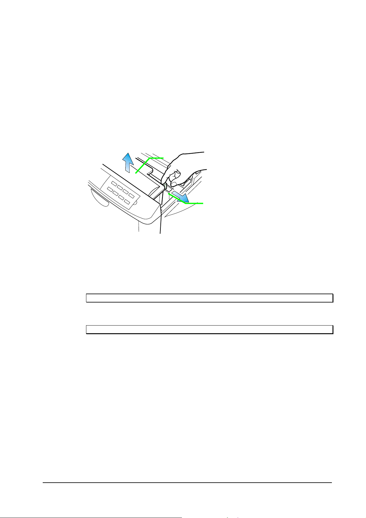
Paper Feed Unit
To avoid print quality problems due to paper dust and debris, clean the paper feed
unit ➊ in the following manner.
Pull the paper feed unit release lever up and draw the paper feed unit all the way out
until it stops. Wipe the paper dust on the registration roller ➋ and the paper ramp ➌
using the wiper cloth ➍ included in the toner kit.
Do not touch the transfer roller
paper ramp.
➍
➌
➎
➊
(black sponge roller) when wiping the
➎
➋
3-11
FS-1200
Page 62

Replacing the developer
In case that the developer unit is to be removed from the printer for shipment or
replacing to a new one, it should be handled following the instructions below.
Also, a new developer unit, after installing, needs a special treatment that repletes
the developer with toner for printing. This can be done by using the front control
panel (See section
Feeding toner into the new developer
Maintenance
Replacing the developer
on page 3-13).
Shipping the developer unit
The printer is supplied with a plastic bag that should be retained for future shipment
of the developer.
Flap down the magnet roller protective cover, then refer to the diagram below:
➊
Put the developer into the plastic bag
Plastic bag
.
3-12
FS-1200
Page 63

Maintenance
Replacing the developer
Feeding toner into the new developer
The new developer unit is shipped from the factory with no toner contained. The
developer can be automatically repleted with toner when a toner container is
installed onto it and the printer is turned on. However, because the toner reservoir in
the developer has a large capacity, it requires a lengthy period of time until a
substantial amount of toner has been fed to get the printer ready. (A new developer
needs approximately 200g for triggering the sensor inside.)
A great many seconds of time for this is greatly deducted by using the service menu
in the printer’s mode select routine as accessed by its front control panel. Follow
these steps to use this feature, top to bottom (For details on using the front control
panel keys, refer to section
Key to press: Display to show:
Mode Select Menu
diagram on page 2-16.
MODE
✚ (repeatedly)
Others>
4
✚ (repeatedly)
4
ENTER
ENTER
Turn printer power off, then on.
>Service>
>>Developer
>>Developer?
The printer enters the
service mode and the
developer u n i t an d t h e
toner feeder motor are
continually activated.
When printer power is turned on again, the printer continually engages in this mode
for a period of approximately 7 minutes for model
-1200, after which the printer
FS
reverts to the ready state.
3-13
FS-1200
Page 64

Updating the engine firmware
The printer accepts update of the engine firmware as well as th e localized front panel
message data through the parallel interface. Updating using these data is
implemented by directly rewriting the flash memory in the printer’s engine board.
The printer must be in the
firmware.
supervisor
Maintenance
Updating the engine firmware
mode (See page 3-16) to update the engine
Note.
Note.
This applies the engine firmware only. The controller firmware is updated by
replacing
Kyocera supplies three types of data for updating the engine firmware depending on
the purpose of update. These are:
#
#
#
These data may be stored in a memory card for field use. To store (write) data in a
memory card, and reread them into the printer through the slot, refer to the printer’s
User’s Manual
Each single data must be written on a memory card. Do not write more than one data
on a memory card.
.
DIMM
Engine firmware data
Front panel initialization data (required to reprogram the panel message)
Front panel message data
.
3-14
FS-1200
Page 65

Updating the engine firmware
Engine/front panel data format
The data is identified using the following naming syntax:
Maintenance
De4630.dat
➊ ➋➌ ➍
Identifies…
de:
➊
➋
➌
➍
Engine firmware data
dm
: Front panel message data
46
: FS-1200
Version of data
dat
: Engine firmware data
dan
: Panel message data for Danish
swe
: Panel message data for Swedish
ita
: Panel message data for Italian
spa
: Panel message data for Spanish
3-15
FS-1200
Page 66

Updating the engine firmware
Downloading data from the parallel interface
To download data from the parallel interface:
Perform, from top to bottom: Then the display shows:
Turn printer power on. Make sure the printer is
Ready
.
At the DOS prompt, execute the following command:
!R! BOOT “SPR”;
—Do not add an EXIT; command in the abo ve.
Note
The display should indicate
Supervisor Mode
.
Ready
Supervisor mode
Maintenance
DOS COPY the data to download from the host
computer.
Check the display reverts to
Turn power off, then on again. Check the display
shows Ready. If not, refer to
section that follows.
Ready
.
Downloading errors
Downloading
Ready
Confirm the status page shows the new engine version (See
the message display indicates
Call service person Dn (n=0, 1, …)
Downloading data from a memory card on page 3-17.
Appendix B
, refer to section
, page B-4). If
3-16
FS-1200
Page 67

Updating the engine firmware
Downloading data from a memory card
To download data written in a memory card to the printer:
Perform, from top to bottom: Then the display to show:
Insert the memory card in the printer’s memory card
slot (at the right side).
Turn printer power on. The printer automatically reads
data in the memory card, indicating
the message panel.
When the data is successfully read, the message display
indicates
Turn printer power off.
Remove the memory card from the printer.
Turn printer power on again. Check the display shows
Ready. If not, refer to Downloading errors section that
follows.
Supervisor mode
.
Downloading
on
Downloading
Supervisor mode
Ready
Maintenance
Confirm the status page shows the new engine version (See
the message display indicates
Call service person Dn (n=0, 1, …)
Appendix B
, refer to section
, page B-4). If
Downloading errors below.
Downloading errors
The following messages are indicated on the message display when an error occurred
during downloading data.
Error message Meaning Corrective action
Call service person
D0—
Checksum error
Call service person
D1
—Machine
compatibility error
Call service person
D2—
Version compatibility
error
Call service person
Checksum error occurred during
downloading. The engine ROM is
empty.
The data to be downloaded is not
compatible with the printer.
The version of the data does not
match the current engine version.
The data to be downloaded is Obtain the co rrect data.
3-17
Turn printer power off once, then
on again. Try downloading again.
Obtain correct data for the
printer mo del.
Obtain the correct version of
data.
FS-1200
Page 68

D3—
Data error corrupted.
Maintenance
Updating the engine firmware
3-18
FS-1200
Page 69

Adjusting the transfer bias for thick paper
Adjusting the transfer bias for thick paper
Maintenance
Printing on paper with extra thickness of 91 to 200 g/m2, such as postcards,
envelopes, etc., tend to result in faint printing because of insufficient penetration of
transfer bias developer at the transfer roller. For the satisfactory transferring process
on different paper thickness, the transfer bias is user-switchable from -1.8 kV to -2.5
kV (limit), or vice versa, by using the printer’s operator panel.
To increase the transfer bias for a type of thick paper, perform the following steps,
top to bottom:
Key to press: Display to show:
MODE
✚ (repeatedly)
ENTER
✚
ENTER
Double-sided printing using a DU-20/DU-21 duplexer automatically introduces the
higher setting of the transfer bias.
Paper type
Normal
Paper type
Normal ?
Paper type
Thick ?
The transfer bias is raised
for thick paper.
OHP
,
3-19
FS-1200
Page 70

This page left intentionally blank
Maintenance
Updating the engine firmware
3-20
FS-1200
Page 71

Chapter Four OPERATION OVERVIEW
Page 72

Chapter Four
Electrophotographics system 4-4
Photoconductive drum 4-5
Charging the drum 4-6
Toner 4-7
Exposure 4-8
Scanner unit 4-10
Scanning laser 4-12
Development 4-13
Developing roller bias 4-14
Transfer 4-16
Fusing 4-17
Drum cleaning and erasing static charge 4-18
Typical photo process timing chart 4-19
Paper feeding system 4-21
Paper feed components/signals 4-22
Cassette feeding 4-23
Manual/multi purp ose tray feeding 4-24
Paper jam sensing 4-25
Print timing charts 4-27
Basic engine functions 4-32
Basic sequence of operation 4-33
OPERATION OVERVIEW
Engine controller system 4-34
Flash memory 4-34
High-voltage generator 4-34
Laser scanner control 4-35
Polygon motor control 4-35
Safety interlock 4-36
The engine gate array 4-37
Pin assignment 4-38
Power supply 4-42
Logic controller system 4-44
Logic controller sp ecifications 4-45
Printing data processing 4-47
API ROM socket (U103) 4-48
API ROM socket pin assignment 4-49
System ROM (YS101) 4-50
RAM (U109,U110) 4-51
Memory card slot interface 4-51
Option interface 4-51
Option interface pin assignment 4-52
Parallel interfa ce 4-53
Page 73

Serial interface (Option) 4-53
Debugging outputs 4-54
Engine interface 4-54
Engine interface connector assignment 4-55
Signals used for the engine interface 4-56
Engine interface signals 4-57
Page 74

Electrophotographics system
Electrophotography is the technology used in laser printing which transfers data representing texts
or graphics objects into a visible image which is developed on the photosensitive drum, finally
fusing on paper, using light beam generated by a laser diode.
The key features for the electrophotography system used in the printer are:
Operation overview
Electrophotographics system
!
600 dpi resolution
!
Newly developed organic photoconductor drum with no heating device
!
Diode laser scanning
!
Mono component toner
The electrophotography system of the printer performs a cyclic action made of seven steps as
shown below.
2 Exposure
1 Main Charging
3 Developing7 Erasing
6 Cleaning
4 Transfer
5 Fusing
4-4
FS-1200
Page 75

Operation overview
Electrophotographics system
Photoconductive drum
The durable layer of organic photoconductor (OPC) is coated over the aluminum cylinder base.
The OPC tends to reduce its own electrical conductance when exposed to light. After a cyclic
process of charging, exposure, and development, the electrostatic image is constituted over the
OPC layer.
Since the OPC is materialized by resin, it is susceptible to damage caused by sharp edges such as a
screwdriver, etc., resulting in a print quality problem. Also, finger prints can cause deterioration of
the OPC layer, therefore, the drum unit (in the process unit) must be handled with care. Substances
like water, alcohol, organic solvent, etc., should be strictly avoided.
As with all other OPC drums, the exposure to a strong light souce for a prolonged period can cause
a print quality problem. The limit is approximately 500 lux for less than five minutes. If the drum
unit (process unit) remains removed from the printer, it should be stored in a cool, dark place.
Photoconductive layer
Aluminum base cylinder
4-5
FS-1200
Page 76

Operation overview
Electrophotographics system
Charging the drum
Figure below is a simplified diagram of the electrophotographics components. Charging the drum
is done by the main charger wire (in the main charger unit) marked A in the diagram.
A
B
As the drum (B) rotates in a “clean (neutral)” state, its photoconductive layer is given a uniform,
positive (+) electrical charge dispersed by the main charger wire (A).
Due to high-voltage scorotron charging, the charging wire can get cont aminated by oxidiz ation and
therefore must be cleaned periodically from time to time using the method explained in section
Main charger unit
such as black streaks caused by the oxide ac-cumulated around the charging wire.
on page 3-7. Cleaning the charging wire prevents print quality problems
4-6
FS-1200
Page 77

Operation overview
Electrophotographics system
Toner
The toner is fed from the toner pack TK-25. The toner is comprised of the following substances as
depicted below.
Single component toner TK-25
A
B
C
D
Resin
A -
Magnetite
B -
Silica
C -
Polisher
D -
4-7
FS-1200
Page 78

Operation overview
Electrophotographics system
Exposure
The charged surface of the drum (“B”) is then scanned by the laser beam from the scanner unit
(“A”).
A
B
4-8
FS-1200
Page 79

Operation overview
Electrophotographics system
The laser beam is switched on for a black dot and off for a white (blank) dot according to the print
data. Whenever it is illuminated by the laser beam, the electrical resistance of the photoconductor
is reduced, the potential on the photoconductor is also lowered to 95V, effectively driving the
charge through the OPC layer down to the aluminum base.
+++++
OPC LAYER
ALUMINUM
LASER BEAM
++++
----
++++
350-390V
95V
0V
LASER BEAM
4-9
FS-1200
Page 80

Operation overview
Electrophotographics system
Scanner unit
The 600 dpi scanner unit includes the diode laser that produces the 670 nm wavelength laser beam.
This wavelength is specifically designed to match the photoconductive response of the OPC drum.
+
To drum
'
&
%
*
$
(
)
#
"
4-10
FS-1200
Page 81

Operation overview
Electrophotographics system
"
Laser diode -
#
Collimeter lens -
$
Cylindrical lens -
%
Polygon mirror (motor) -
one scanned line width on the drum when laser beam scans on it.
&
Primary f-theta lens -
'
Secondary f-theta lens -
edges. The effective length of line (“A,” “B” below) the laser beam draws on the drum becomes longer as the laser beam
hits closer to the drum edges. In the figure below, distances represented by “A” and “B” are not the same (A>B) until the
f-theta lenses are provided between the polygon mirror and the drum (A’=B).
emits diffused, visible laser.
aligns the laser beam to the cylindrical lens.
compensates the slant angle at which the laser beam hits a polygon mirror segment.
has six mirror segments around its octagonal circumference; each mirror corresponding to
See below.
The primary (above) and secondary f-theta lenses equalize focusing distortion on the drum
(
Diversion mirror -
the drum.
)
Protective glass -
*
Sensor mirror -
+
Beam detect or sensor -
engine controller to start activating the paper feeding system.
diverts the laser beam vertically onto the drum. Note the diffused laser beam finally pin-points on
prevents dust, debris, etc., from entering the scanner assembly.
bends the very first shot of a laser scan towards the beam detection sensor (See next.).
when shone by the sensor mirror above, this photosensor generates a trigger signal for the
4-11
FS-1200
Page 82

Operation overview
Electrophotographics system
Scanning laser
The laser beam hits one of six polygonal mirrors. As the mirror revolves (at the revolution of
17,000 rpm for model FS-1200), the laser beam reflects off of it and reaches the charged drum surface in a lengthwise manner.
A pair of (plastic) lenses provides focusing the horizontally sweeping laser beam onto the drum.
As the drum rotates, the laser beam sweeps the entire length of the drum so that the drum’s entire
circumference is exposed to the laser beam. The revolution of the polygon mirror motor and the
drum itself is timing-controlled so that each successive sweeping of the laser beam produces a
inch offset. The printer’s controller system continuously turns the laser beam on and off to put a
dot at every
1
/
inch distance horizontally. The diameter of a dot is typically 70 µm.
600
Synchronizing the output data with one scanning line is achieved by the photo sensor provided
next to the first mirror. At the beginning of each laser sweeping, the beam hits the photo sensor
which in turn sends a command to the logic controller for synchronization.
1
/
600
4-12
FS-1200
Page 83

Operation overview
Electrophotographics system
Development
The latent image constituted on the drum is developed into a visible image. The developing roller
contains a 3-pole (
Toner attracts to the developing roller since it is powdery ink made of black resin bound to iron
particles. A magnetized blade positioned approximately 0.25-0.35 mm above the developing roller
constitutes a smooth layer of toner in accordance with the roller revolution.
S-N-S
) magnet core and an aluminum cylinder rot ating around the magne t core.
Drum
0.1mm
Magnetism
N
N
S
S
Blade
Magnet
0.25-0.35mm
S
Developing roller
4-13
FS-1200
Page 84

Developing roller bias
p
r
A
Operation overview
Electrophotographics system
The developing roller is connected to a
AC
-weighted, positive DC power source. Toner on the developing roller is given a positive charge. The positively charged toner is then attracted to the areas
of the drum which was exposed to the laser light. (The gap between the drum and the developing
roller is approximately 0.3 mm.) The non-exposed areas of the drum repel the positively-charged
toner as these areas maintain the positive charge.
The developing roller is also biased with an ac potential to apply compensation to the toner’s attraction and repelling actions for more contrast in the development.
Blade
Develo
Drum
. rolle
Toner
Toner sensor
C+DC
Toner
Drum
Develop. roller
4-14
FS-1200
Page 85

Operation overview
Electrophotographics system
Adjusted to prevent grey background
Surface
potential =
370V
+
+++ ++
Developing
Developing
+++ + ++
95V
Developing roller bias
240V DC+1.4kV AC
(f=2.4 kHz)
A toner replenishment sensor is provided within the developer. As the toner supply from the toner
container dwindle s and the toner level lowers in the reservoir, the sensor t ranslates it through i ts
diaphragm, urgi ng t he toner motor to feed more toner.
Sensable
level
Diaphragm
Toner
Developer unit
4-15
Toner sensor
FS-1200
Page 86
Operation overview
Electrophotographics system
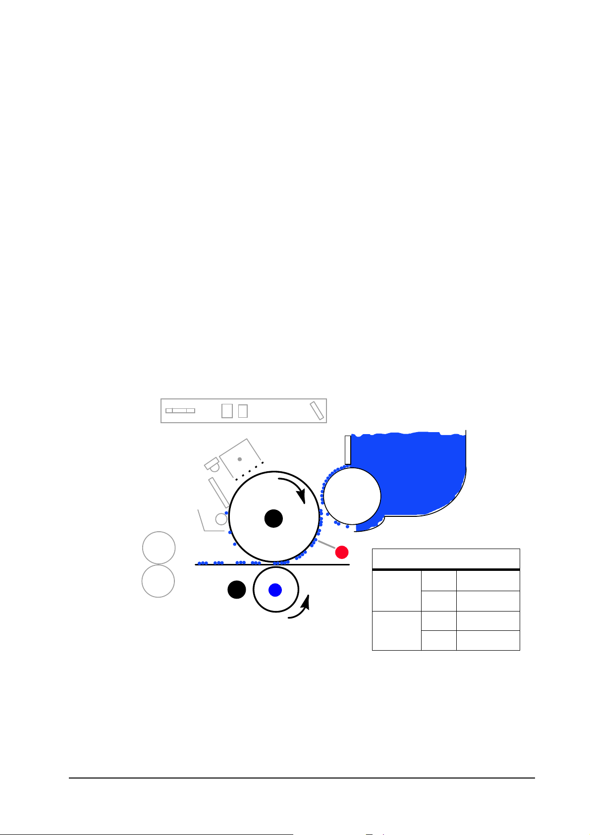
Transfer
The image developed by toner on the drum (“A” below) is transferred onto the paper using the
electric charge attraction given by the toner itself and the transfer roller (“B” below). The transfer
roller is negatively biased so that the positively charged toner is attracted onto the paper while it is
pinched by the drum and the transfer roller.
The paper is automatically peeled off the drum because of the small diameter of the drum. To prevent thin paper wrapping around the drum, the static discharger brush is provided to reduce the attraction of the negatively charged paper to the positively charged drum.
A
+
B
-
Current
Voltage
Transfer bias
5µA
10µA
1.8KV Normal
2.5KV Thick
Normal, thick
B5 and smaller
The nominal transfer bias is set to approximately -1.8 kV (limit) with the current of 5µA. Since
thicker paper (91 to 200 g/m
2
) such as postcards,
OHP
, envelopes, etc., tend to require more bias
potential for the satisfactory transferring process, the transfer bias is user-switchable to -2.5 kV
DU
(limit) by using the printer’s operator panel. Double-sided printing using a
-20/
DU
-21 duplexer
automatically increases the transfer bias to the above value.
4-16
FS-1200
Page 87

Operation overview
Electrophotographics system
Fusing
The toner on the paper is permanently fused onto the paper as it passes between the florin-finished
heat roller (“A” below) and the pressure roller (“B” below) in the fuser unit. The toner is molten
and pressed into the paper. The heat roller has a halogen lamp, turning frequently on and off to
maintain a preheat temperature at approximately 180°C.
The heat roller temperature is constantly monitored by the engine control circuit using a thermistor. For safety against overheating, the fuser system is protected by a triac which automatically
opens power to the halogen lamp. If the temperature exceeds 350°C, it activates the thermo-cut
device to interrupt open power to the halogen lamp.
A
B
4-17
FS-1200
Page 88

Operation overview
Electrophotographics system
Drum cleaning and erasing static charge
The drum needs to be physically cleaned of toner remaining on its surface in the previous rotation.
The cleaning blade (A below) scrape against the drum to remove the waste toner. To collect the
waste toner, the waste toner bottle is connected to the end of the spiral roller (C below).
B
A
C
After the drum is physically cleaned, it then must be cleaned to an electrically neutral state. This is
necessary to erase any residual positive charges, ready to accept the next uniform charge. The
residual charge is canceled by exposing the drum to the light emitted from the eraser LED (
above) in the similar manner as described in page 4-6. This lowers the electrical conductivity of
the drum surface making the residual charge on the drum surface escape to the ground.
B
4-18
FS-1200
Page 89

Operation overview
Electrophotographics system
Typical photo process timing chart
The following chart shows the signals used for photo processing. These signals activate the corresponding device in the following timing sequences. A simple description for these signals follow.
MOTOR
PAPER
MHVDR
ERASER
BIAS
THVDR:
Page 1 Page 2
A
B
C
E
D
MHVDR (Main High Voltage DRive) -
kept on during the job is processed.
ERASER
BIAS -
on the current paper size (B) and turns off between pages (C).
- turns on the eraser (
turns on the developer bias (on the magnet roller). The duration of this signal is dependent
drives main charger with high voltage bias. This signal is
LED
array) as soon as the motor begins r evolving (A above).
4-19
FS-1200
Page 90

Operation overview
Electrophotographics system
THVDR (Transfer High Voltage Drive) -
verse (+520V) at the beginning of a print job (D)until the paper is actually fed onto the transfer
roller. This prevents contamination on the back side of paper by effectively repelling the toner
during the paper is not present between the drum and the transfer roller. The transfer bias is kept
on during a print job (E).
turns on the transfer bias. Note that the transfer bias is re-
4-20
FS-1200
Page 91

Paper feeding system
The paper feeding system picks up paper from the paper cassette or the manual feeding tray and at
a precise timing feeds it to the electrophotography system for developing image on the paper. It finally delivers the printed page to either the face-down or face-up tray.
The figure below shows the paper feeding path within the printer.
Operation theory
Paper feeding system
)
#
(
'
%
&
$
"
"
Paper (cassette). #Paper feed roller+clutch+sensor. $Registration rollers+clutch+sensor. %Drum.
&
Transfer roller. 'Fuser rollers. (Exit rollers+sensor.)Manual feed roller+clutch+sensor.
Following on the next page is another diagram showing locations of sensors, roller, and solenoids
arranged along with this paper path.
4-21
FS-1200
Page 92

Paper feed components/signals
*
EXITJ
JAM0
Face-dow n r ol lers
Engine Controller
*
MMOT*
MOTOR
Operation theory
Paper feeding system
MFDDR*HANDS
FDCL2*
*
MFEED*
*
REGDR
REGCL*
JAMR
FEEDS
JAM0
*
*
PAPER
FEDDR
FDCL1*
Exit
sensor
Exit rollers
Clutches Sensors Rollers
Main motor
Heat Roller
Pressure Roller
Drum
Transfer roller
Paper Ca ssett e
Regist.
clutch
Regist rollers
Regist
sensor
Paper
sensor
Feed
clutch
Manual
feed
clutch
Manual
feed
sensor
PAPRPATH.CDR
4-22
FS-1200
Page 93

Cassette feeding
Operation theory
Paper feeding system
The main logic controller sends the
essing. The engine controller
tion rollers, and the fuser heater. The engine controller then issues the
PRINT
* signal to the engine controller aft er finishing data p roc-
CPU
then starts the main motor (
MOTOR*
), polygon motor, registra-
FEDDR*
signal to connect the
main motor power to the paper feed tires. The tires feed the top sheet in the paper stack in the cassette towards the registration rollers until the paper reaches the registration jam sensor (FEEDS*).
As the engine controller sends VSREQ* to the main logic controller, the main logic controller subsequently issues VSYNC* to activate the registration rollers, thus starting to feed paper towards
the drum.
The paper is advanced to the drum, to the fuser unit, triggering the exit sensor (
EXITJ*
), and finally
delivered either to the face-down tray or the face-up tray as switched by the output stack selector
tab.
4-23
FS-1200
Page 94

Operation theory
Paper feeding system
Manual/multi purpose tray feeding
The printer recognizes the existence of paper on the manual feed or multi purpose tray when the
manual feed sensor is pushed up (
In manual paper feed mode, the paper placed on the manual feeding tray or multi purpose tray is
drawn in when the manual feed clutch is energized by the
roller.
HANDS
).
FEDDR*
signal to drive the manual feed
The subsequent print process is identical to the above section.
4-24
FS-1200
Page 95

Operation theory
Paper feeding system
Paper jam sensing
The registration sensor and the exit (fuser) sensor keep track of the paper sent through the printer’s
paper path by watching the time of period during which either sensor is kept activated.
Registration sensor -
flector (shiny mirror surface) at the end of the actuator is in the position that can reflect the light to
shine the receptor. As the top edge of the paper reaches the registration sensor, the reflector is
pushed up and the light is interrupted(➋), triggering the sensor.
A photo reflector sensor is used. While the paper is not present (➊), the re-
➊
➋
4-25
FS-1200
Page 96

Operation theory
Paper feeding system
Exit sensor -
fuser board. The actuator is in the way back at the fuser outlet. The reflector at one end of the actuator is normally seated in-between the photo transmitter and sensor (➊). It is dressed away out of
them when the paper in the fuser sensor pushed up the actuator (➋), allowing the light to hit the receptor and turning the sensor circuit on.
This is a photo penetration sensor, combined with an actuator arm extending to the
➊
➋
On detecting a paper jam, the engine controller stops printing action and shows the “Paper jam”
message. After removing paper jam, the printer resumes printing when either the toner access door
or the feed assembly is once opened and closed. If paper jammed past the exit sensor, the printer
will not attempt to print the same page.
Paper coming from the paper cassette should pass the registration sensor in a predetermined period
of time that begins with the feed clutch turned on (FEDDR*).
4-26
FS-1200
Page 97

Print timing charts
Operation theory
Print timing charts
4-27
FS-1200
Page 98

Operation theory
Print timing charts
4-28
FS-1200
Page 99

Operation theory
Print timing charts
4-29
FS-1200
Page 100

Operation theory
Print timing charts
4-30
FS-1200
 Loading...