

Page 1
Laser printer
SERVICE
MANUAL
Published in Dec. ’01
Page 2

Revision history
Version Replaced pages RemarksDate
1.0
5-Dec-2001
Page 3

Safety precautions
This booklet provides safety warnings and precautions for our service personnel to ensure the safety of
their customers, their machines as well as themselves during maintenance activities. Service personnel
are advised to read this booklet carefully to familiarize themselves with the warnings and precautions
described here before engaging in maintenance activities.
Page 4
Safety warnings and precautions
Various symbols are used to protect our service personnel and customers from physical danger and
to prevent damage to their property. These symbols are described below:
DANGER: High risk of serious bodily injury or death may result from insufficient attention to or incorrect
compliance with warning messages using this symbol.
WARNING:Serious bodily injury or death may result from insufficient attention to or incorrect compliance
with warning messages using this symbol.
CAUTION: Bodily injury or damage to property may result from insufficient attention to or incorrect
compliance with warning messages using this symbol.
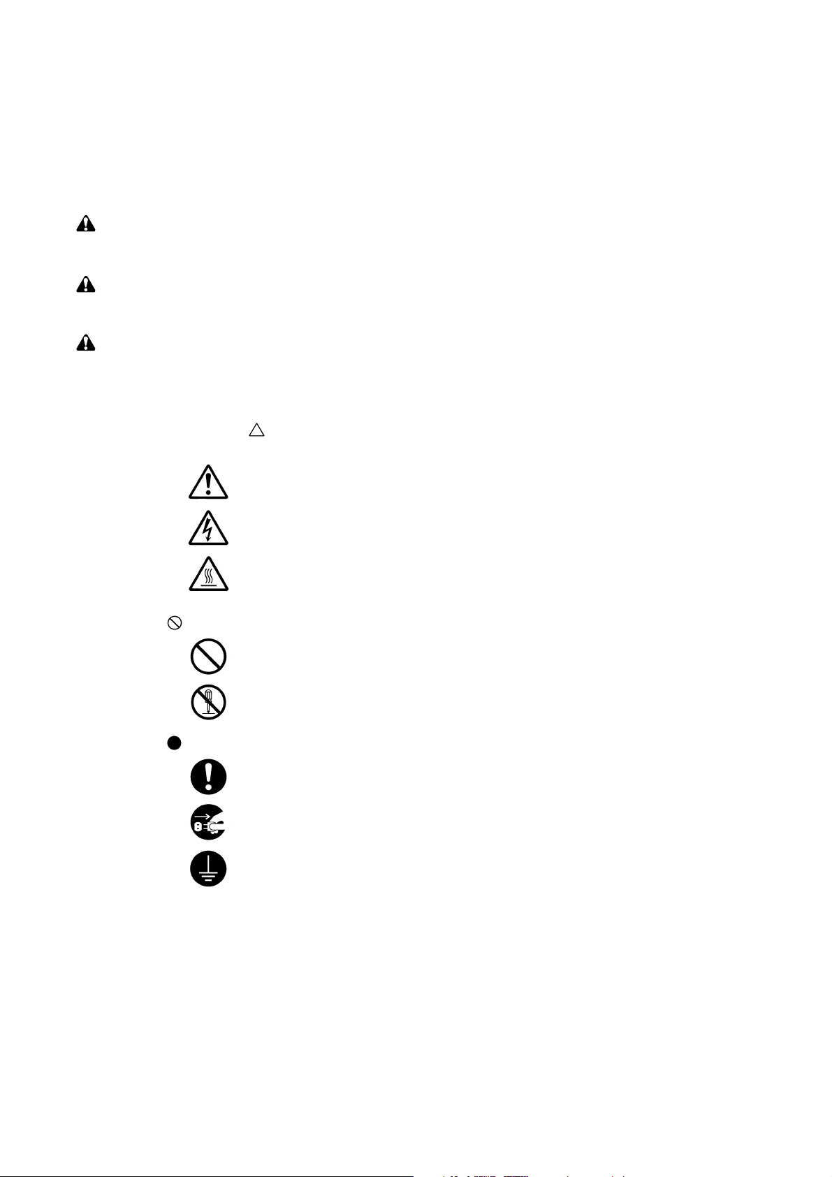
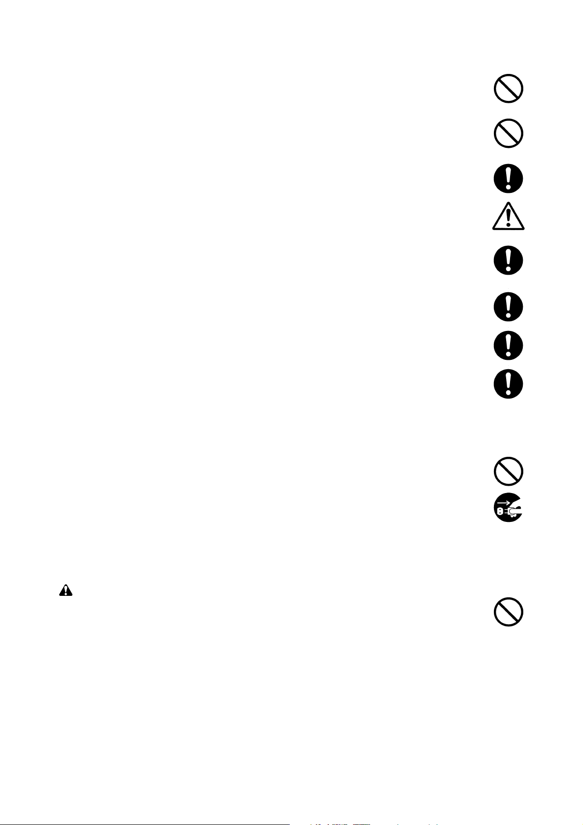
Symbols
The triangle ( ) symbol indicates a warning including danger and caution. The specific point
of attention is shown inside the symbol.
General warning.
Warning of risk of electric shock.
Warning of high temperature.
indicates a prohibited action. The specific prohibition is shown inside the symbol.
General prohibited action.
Disassembly prohibited.
indicates that action is required. The specific action required is shown inside the symbol.
General action required.
Remove the power plug from the wall outlet.
Always ground the printer.
Page 5
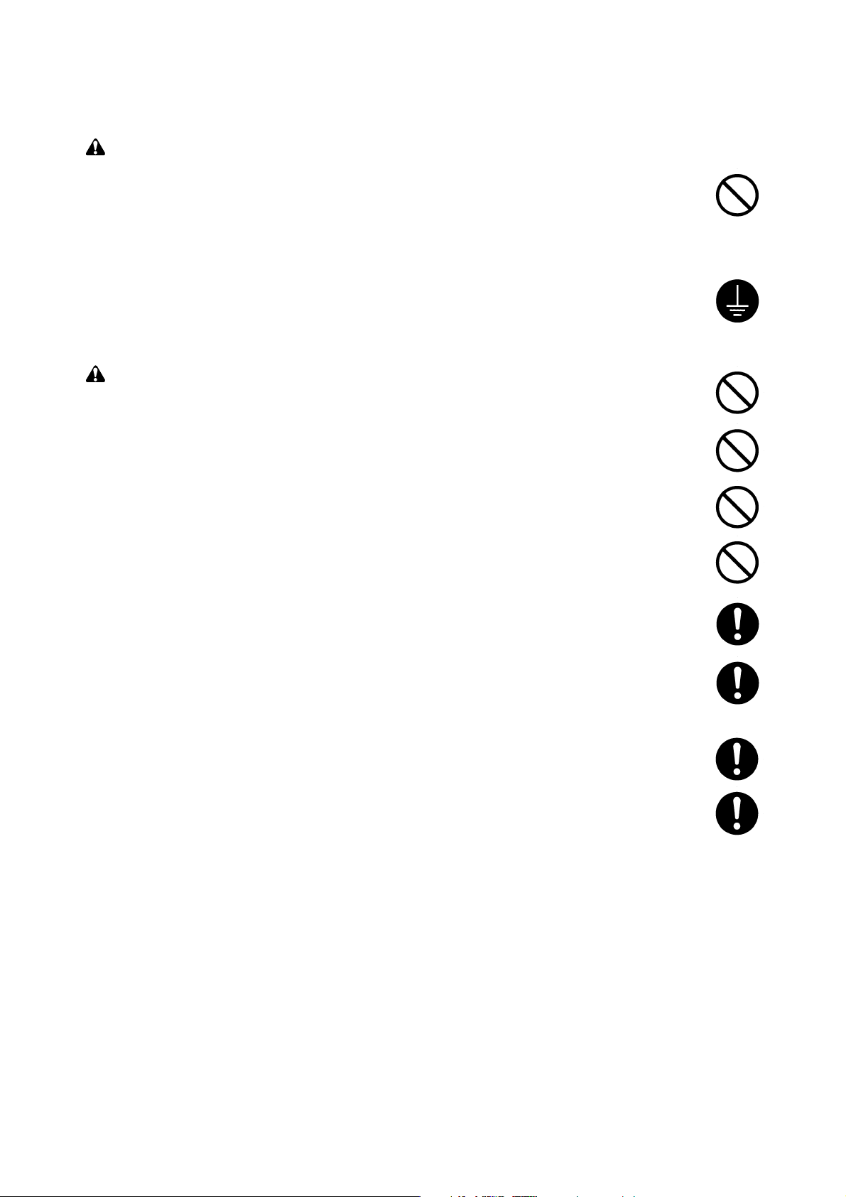
1. Installation Precautions
WARNING
•Do not use a power supply with a voltage other than that specified. Avoid multiple connections to
one outlet: they may cause fire or electric shock. When using an extension cable, always check
that it is adequate for the rated current. ............................................................................................
• Connect the ground wire to a suitable grounding point. Not grounding the printer may cause fire or
electric shock. Connecting the earth wire to an object not approved for the purpose may cause
explosion or electric shock. Never connect the ground cable to any of the following: gas pipes,
lightning rods, ground cables for telephone lines and water pipes or faucets not approved by the
proper authorities. .............................................................................................................................
CAUTION:
•Do not place the printer on an infirm or angled surface: the printer may tip over, causing injury. ....
•Do not install the printer in a humid or dusty place. This may cause fire or electric shock. ..............
• Do not install the printer near a radiator, heater, other heat source or near flammable material.
This may cause fire. ..........................................................................................................................
• Allow sufficient space around the printer to allow the ventilation grills to keep the machine as cool
as possible. Insufficient ventilation may cause heat buildup and poor copying performance. ..........
• Always handle the machine by the correct locations when moving it. ..............................................
• Always use anti-toppling and locking devices on printers so equipped. Failure to do this may
cause the printer to move unexpectedly or topple, leading to injury. ................................................
• Avoid inhaling toner or developer excessively. Protect the eyes. If toner or developer is
accidentally ingested, drink a lot of water to dilute it in the stomach and obtain medical attention
immediately. If it gets into the eyes, rinse immediately with copious amounts of water and obtain
medical attention. ..............................................................................................................................
•Advice customers that they must always follow the safety warnings and precautions in the
printer’s instruction handbook. ..........................................................................................................
Page 6
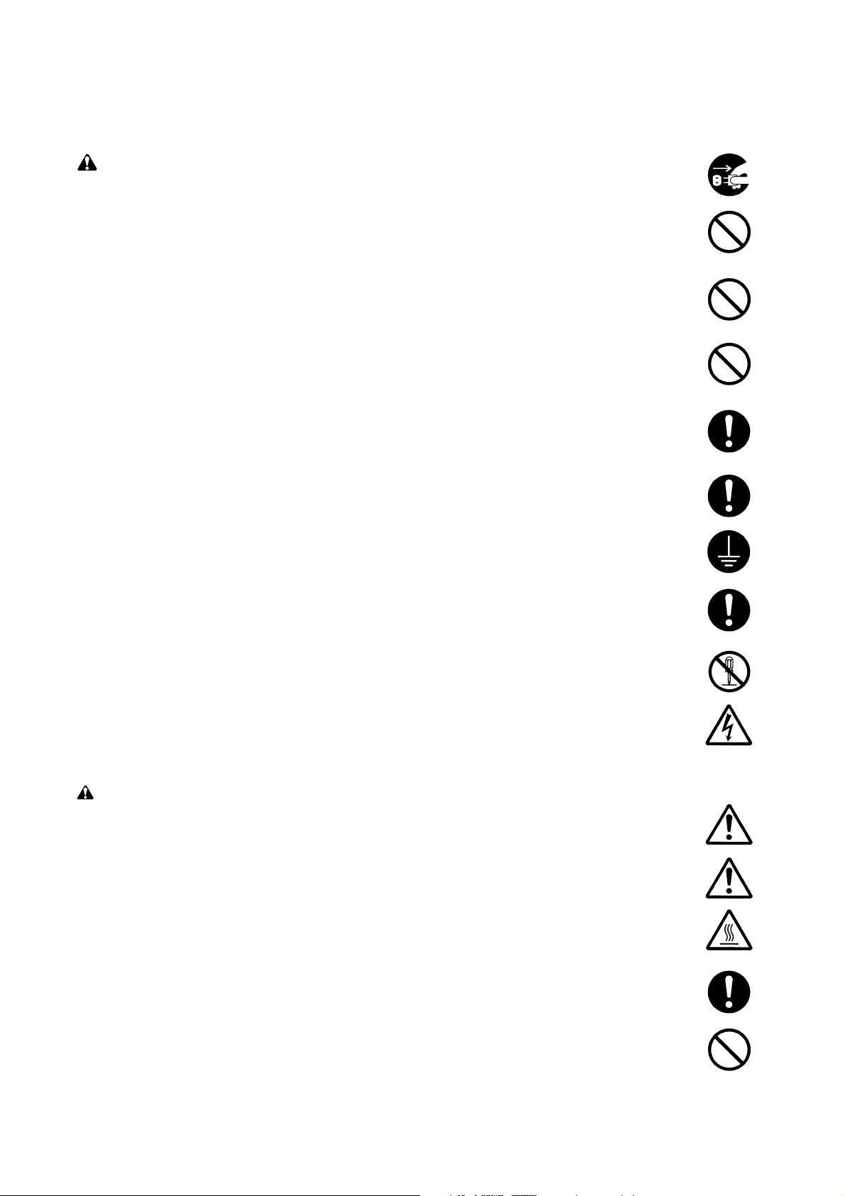
2. Precautions for Maintenance
WARNING
• Always remove the power plug from the wall outlet before starting machine disassembly. .............
• Always follow the procedures for maintenance described in the service manual and other related
brochures. .........................................................................................................................................
• Under no circumstances attempt to bypass or disable safety features including safety
mechanisms and protective circuits. .................................................................................................
• Always use parts having the correct specifications...........................................................................
• Always use the thermostat or thermal fuse specified in the service manual or other related
brochure when replacing them. Using a piece of wire, for example, could lead to fire or other
serious accident. ...............................................................................................................................
•When the service manual or other serious brochure specifies a distance or gap for installation of a
part, always use the correct scale and measure carefully. ...............................................................
• Always check that the printer is correctly connected to an outlet with a ground connection. ...........
• Check that the power cable covering is free of damage. Check that the power plug is dust-free. If
it is dirty, clean it to remove the risk of fire or electric shock. ............................................................
• Never attempt to disassemble the optical unit in machines using lasers. Leaking laser light may
damage eyesight. ..............................................................................................................................
• Handle the charger sections with care. They are charged to high potentials and may cause
electric shock if handled improperly. .................................................................................................
CAUTION
•Wear safe clothing. If wearing loose clothing or accessories such as ties, make sure they are
safely secured so they will not be caught in rotating sections. .........................................................
• Use utmost caution when working on a powered machine. Keep away from chains and belts. .......
• Handle the fixing section with care to avoid burns as it can be extremely hot. .................................
• Check that the fixing unit thermistor, heat and press rollers are clean. Dirt on them can cause
abnormally high temperatures. .........................................................................................................
• Do not remove the ozone filter, if any, from the printer except for routine replacement. ..................
Page 7
• Do not pull on the AC power cord or connector wires on high-voltage components when removing
them; always hold the plug itself. ......................................................................................................
•Do not route the power cable where it may be stood on or trapped. If necessary, protect it with a
cable cover or other appropriate item. ..............................................................................................
• Treat the ends of the wire carefully when installing a new charger wire to avoid electric leaks. ......
•Remove toner completely from electronic components. ...................................................................
• Run wire harnesses carefully so that wires will not be trapped or damaged. ...................................
• After maintenance, always check that all the parts, screws, connectors and wires that were
removed, have been refitted correctly. Special attention should be paid to any forgotten
connector, trapped wire and missing screws. ..................................................................................
• Check that all the caution labels that should be present on the machine according to the
instruction handbook are clean and not peeling. Replace with new ones if necessary. ...................
• Handle greases and solvents with care by following the instructions below: ....................................
·Use only a small amount of solvent at a time, being careful not to spill. Wipe spills off completely.
· Ventilate the room well while using grease or solvents.
· Allow applied solvents to evaporate completely before refitting the covers or turning the main
switch on.
·Always wash hands afterwards.
•Never dispose of toner or toner bottles in fire. Toner may cause sparks when exposed directly to
fire in a furnace, etc. .........................................................................................................................
• Should smoke be seen coming from the printer, remove the power plug from the wall outlet
immediately. ......................................................................................................................................
3. Miscellaneous
WARNING
• Never attempt to heat the drum or expose it to any organic solvents such as alcohol, other than
the specified refiner; it may generate toxic gas. ................................................................................
Page 8

Contents
Chapter 1
1-1 Printer specifications ....................................................................................................................................... 1-3
1-2 Names of parts ................................................................................................................................................ 1-6
1-3 Safety information ............................................................................................................................................1-7
1-4 Environmental requirements ..........................................................................................................................1-10
1-5 About the toner container .............................................................................................................................. 1-14
Chapter 2
2-1 Unpacking ........................................................................................................................................................2-3
2-2 Installing the printer ......................................................................................................................................... 2-4
2-3 Using the operator panel ............................................................................................................................... 2-15
Chapter 3
3-1 Maintenance/Adjustments ............................................................................................................................... 3-3
Chapter 4
4-1 Electrophotographic system ............................................................................................................................ 4-3
4-2 Paper feeding system .................................................................................................................................... 4-15
4-3 Electrical control system ................................................................................................................................ 4-18
Chapter 5
5-1 General instructions .........................................................................................................................................5-3
5-2 Disassembly .................................................................................................................................................... 5-4
Chapter 6
6-1 Troubleshooting ...............................................................................................................................................6-3
Appendix A
Timing charts ........................................................................................................................................................ A-3
Wiring diagram ...................................................................................................................................................... A-9
Appendix B
Status page ........................................................................................................................................................... B-3
Appendix C
Parallel interface ................................................................................................................................................... C-3
USB interface ........................................................................................................................................................ C-6
Serial interface (Optional) ..................................................................................................................................... C-7
1-1-1
Page 9

Chapter 1
Product Information
Page 10

Chapter 1 Contents
1-1 Printer specifications ...................................................................................................................... 1-3
1-1-1 Specifications ............................................................................................................................ 1-3
(1) Engine ................................................................................................................................. 1-3
(2) Controller ............................................................................................................................. 1-4
(3) Weight and dimensions ....................................................................................................... 1-4
(4) Power requirements ............................................................................................................ 1-5
(5) Environmental requirements ............................................................................................... 1-5
1-2 Names of parts ................................................................................................................................. 1-6
1-2-1 Name of parts ............................................................................................................................ 1-6
1-3 Safety information ........................................................................................................................... 1-7
1-3-1 Safety information ...................................................................................................................... 1-7
(1) Laser safety ......................................................................................................................... 1-7
(2) Laser notice ......................................................................................................................... 1-7
(3) Laser caution label on the scanner unit ............................................................................... 1-7
(4) CDRH regulations (U.S.A.) .................................................................................................. 1-9
(5) Ozone concentration ........................................................................................................... 1-9
(6) Optional equipment ............................................................................................................. 1-9
(7) Important note on the interface connectors ......................................................................... 1-9
1-4 Environmental requirements ........................................................................................................ 1-10
1-4-1 Environmental conditions ........................................................................................................ 1-10
(1) Clearance ...........................................................................................................................1-11
(2) Places to avoid .................................................................................................................. 1-12
(3) Note on power ................................................................................................................... 1-12
(4) Removing the printer ......................................................................................................... 1-13
1-5 About the toner container ............................................................................................................. 1-14
1-5-1 Toner container ........................................................................................................................ 1-14
(1) Toner container handling ................................................................................................... 1-14
(2) Toner container storage ..................................................................................................... 1-15
Page 11

1-1 Printer specifications
1-1-1 Specifications
(1) Engine
Item Specification
Print method
Print speed (when printing
multiple pages)
Resolution (dpi)
Smoothing
First print (A4 or letter, 23 °C),
depends on input data
Warm-up time at 23 °C
Maximum duty cycle (A4)
Process unit life expectancy
Developing
Laser diode
Main charger
Transferring
Separation
Drum cleaning
Drum discharging
Fuser
Paper
Capacity of paper feed trays
(80 g/m2 [0.11 mm thickness])
Electrophotography laser scan
14 pages/min. (A4)
15 pages/min. (Letter)
Fast 1200 mode (1800 horizontal/600 vertical)
600 horizontal/600 vertical
KIR (Kyocera Image Refinement)
22 seconds or less
10 seconds or less (from sleep mode)
15 seconds or less (from power on)
100,000 pages of printing or 3 years, whichever reached first
Mono component developer
Visible laser
Scorotron positive charging
Negative charger roller
Curvature separation
Blade
Eraser lamp (LED array)
Heat roller and press roller
Plain paper: Legal to A5
Cassette: 250 sheets, MP tray: 50 sheets
Capacity of output trays
(80 g/m2 [0.11 mm thickness])
Face-up: 30 sheets, Face-down: 150 sheets
FS-1050
1-3
Page 12

(2) Controller
Item Specification
CPU
System ROM
Font ROM
Optional font ROM (Dip socket)
Main (Video) RAM
Expanding RAM (DIMM slot × 1)
Host interface
Page description language
Standard emulation modes
PowerPC405/200MHz
4 MB Flash DIMM
2 MB (16 M bit × 1)
1 MB (Optional KPDL2 Upgrade kit)
16 MB (Standard-equipped on main board)
Maximum 144 MB (Including the standard 16 MB main RAM)
(Accepts any of 16/32/64/128 MB DIMM)
Parallel: High-speed, bidirectional (IEEE1284)
USB: Revision 1.1 standards
Serial (option) : RS-232C/RS-422A, Max. speed: 115.2 Kbps
(Optional serial interface board)
KUIO-LV (3.3 V)
Prescribe 2e
PCL6, Diablo 630, IBM proprinter X24E, Epson LQ850, Line
printer, KPDL2
(3) Weight and dimensions
Item Specification Item S
Main unit (excl. protrusions)
Width: 378 mm (147/8 inches)
Height: 244 mm (83/4 inches)
Depth: 375 mm (143/4 inches)
Weight: 9.8 Kg (2015/16 lb.)
FS-1050
1-4
Page 13

(4) Power requirements
Item Specification Item S
Vo ltage/current requirement
Watts
220 to 240 V AC ±10 %, 50/60 Hz ±2 %/3.8 A
Normal operation: 265 W
Maximum: 818 W
Standby: 13 W
Sleeping: 5 W
(5) Environmental requirements
Item Specification Item S
Operating temperature and
10 to 32.5 °C (50 to 90.5 °F), 20 to 80 %RH
humidity
Maximum altitude
2,000 m (6,500 feet)
Noise emission (Excluding peaks,
measured at 1 m from printer,
as per ISO7779)
50 dB (A) maximum/28 dB (A) at standby/unmeasureably low
at sleeping)
1-5
FS-1050
Page 14
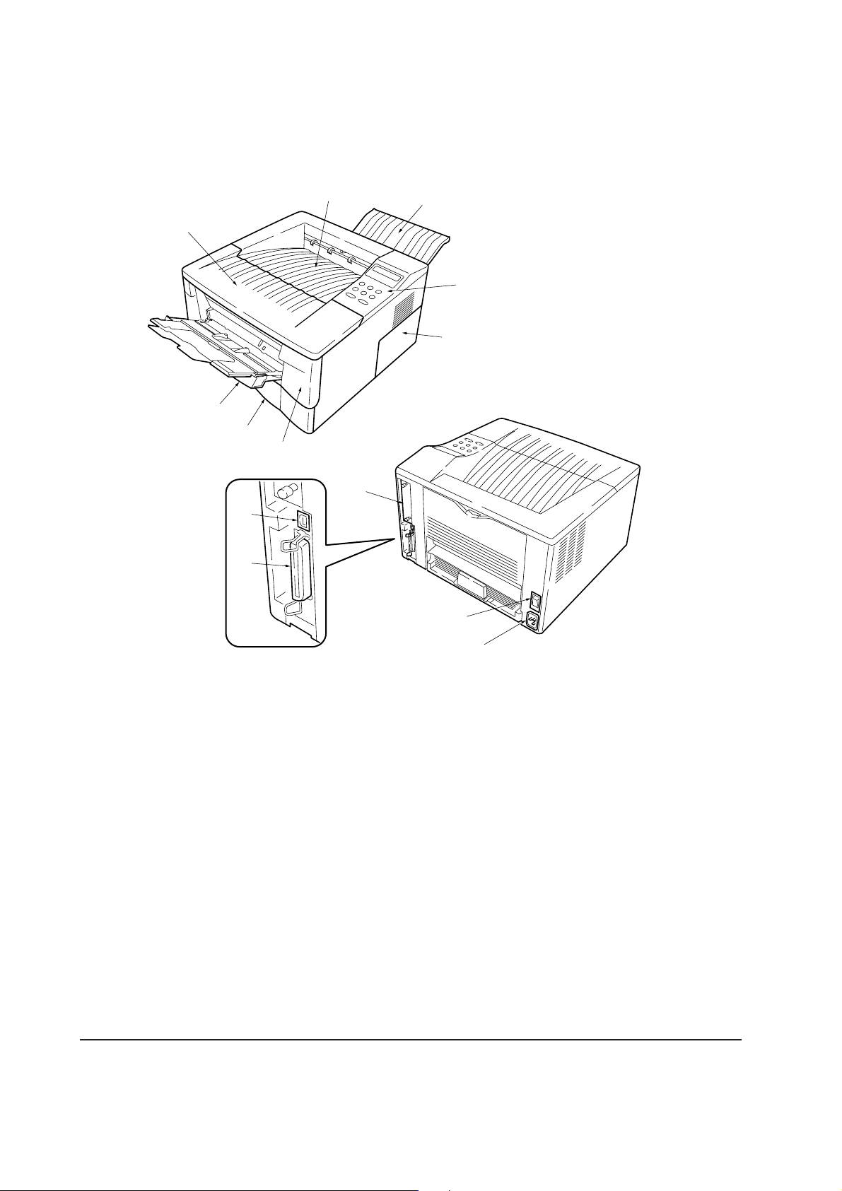
1-2 Names of parts
1-2-1 Name of parts
1
8
7
!
0
6
2
3
5
4
9
1 Top cover
2 Face-down output tray
3 Face-up output tray
4 Side cover
5 Operator panel
6 Front cover
7 Paper cassette
Figure 1-2-1 Name of parts
@
#
8 MP tray
9 Option card slot
0 Parallel interface connector
! USB interface connector
@ Power switch
# AC inlet
FS-1050
1-6
Page 15

1-3 Safety information
1-3-1 Safety information
(1) Laser safety
This printer is certified as a Class 1 laser product under the U.S. Department of Health and Human
Services (DHHS) Radiation Performance Standard according to Radiation Control for Health and
Safety Act of 1968. This means that the printer does not produce hazardous laser radiation. Since
radiation emitted inside the printer is completely confined within protective housings and external
covers, the laser beam cannot escape from the printer during any phase of user operation.
(2) Laser notice
This printer is certified in the U.S. to conform to the requirements of DHHS 21 CFR Subchapter for
Class I (1) laser products, and elsewhere is certified as a Class I laser product conforming to the
requirements of IEC 825.
(3) Laser caution label on the scanner unit
The laser scanner unit has the following label affixed atop. Observe these cautionary statements
and figures when handling the laser scanner unit.
1-7
FS-1050
Page 16
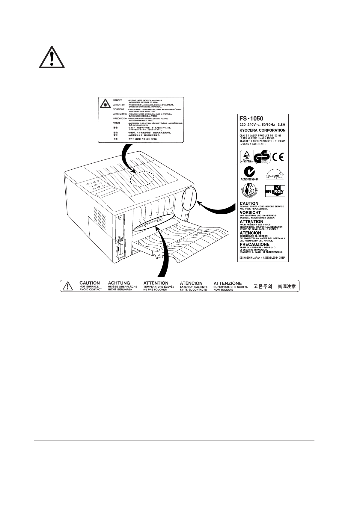
WARNING Use of controls or adjustments or performance of procedures other than those
specified herein may result in hazardous radiation exposure.
Label on the scanner unit
(Inside the printer)
Label on the left cover rear side
-
FS-1050
Label on the fuser unit
Figure 1-3-1 Caution labels
1-8
Page 17

(4) CDRH regulations (U.S.A.)
The Center of Devices and Radiological Health (CDRH) of the U.S. Food and Drug Administration
implemented regulations for laser products on August 2, 1976. These regulations apply to laser
products manufactured after August 1, 1976. Compliance is mandatory for products marketed in
the United States. A label indicating compliance with the CDRH regulations must be attached to
laser products marketed in the United States.
(5) Ozone concentration
The printers generate ozone gas (O3) which may concentrate in the place of installation and cause
an unpleasant smell. To minimize concentration of ozone gas to less than 0.1 ppm, we recommend
you not to install the printer in a confined area where ventilation is blocked.
(6) Optional equipment
The printer may be optionally installed with the following units:
• PF-17 Paper feeder (250 sheets)
• Serial interface board
• Network interface card
• Memory card
(7) Important note on the interface connectors
Be sure to turn off printer power before connecting or disconnecting an interface cable to the printer.
For protection against static discharge which may be applied to the printer’s internal electronics
through the interface connector(s), keep any interface connector which is not in use capped using
the protective cap supplied.
1-9
FS-1050
Page 18

1-4 Environmental requirements
1-4-1 Environmental conditions
The Environmental requirements section on page 1-5 should be observed to ensure the optimum
operation of the printer. The use of the printer in a location which does not satisfy the requirements
may result in troubles and risk shortening its service life.
The printer will work best if it is installed in a location that is:
• Level and well supported (Place the printer on a table or desk.)
• Not exposed to sunlight or other bright light (not next to an uncurtained window). Do not place
the printer on an unstable cart, stand or table.
• Near an AC wall outlet, preferably one that can be used for the printer alone. The outlet should
have a ground slot, or an adapter should be used. If you use an extension cord, the total length of
the power cord plus extension cord should be 17 feet or 5 meters or less.
• Well ventilated, not too hot or cold, and not too damp or dry (See section Environmental
requirements on page 1-5). If you install the printer where the temperature or humidity is outside
the requirements in section Environmental requirements in chapter 1, the best print quality may
not be expected and there will be an increased chance of paper jams.
• Provide a sufficient clearances around the printer to ensure ventilation and ease of access. (See
section Clearance on next page).
FS-1050
1-10
Page 19
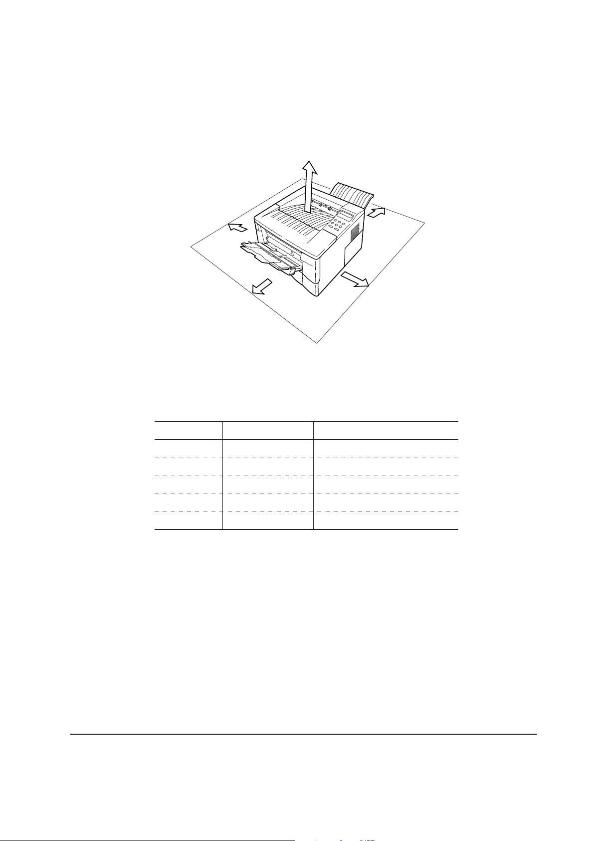
(1) Clearance
5
1
2
3
4
Allow the necessary minimum clearance on all sides of the printer as diagrammed below.
Figure 1-4-2 Clearances
Ref. Clearance Dimensions
1 Left 25 cm (9-7/8 inches)
2 Front 50 cm (19-11/16 inches)
3 Right 25 cm (9-7/8 inches)
4 Back 40 cm (15-3/4 inches)
5 Above 30 cm (11-13/16 inches)
FS-1050
1-11
Page 20

(2) Places to avoid
Avoid installing the printer in locations exposed to:
• Direct drafts of hot or cold air.
• Direct drafts of outside air. (Avoid locations next to outside doors.)
• Sudden temperature or humidity changes.
• Any source of high heat, such as a radiator or stove.
• Excessive dust. Dust and smoke may cause contamination on the laser scanner window, causing
print quality problem.
• Vibration.
• Ammonia fumes or other harmful fumes. (In case of fumigating the room or saturate it with
insecticide, remove the printer first.)
• Avoid greenhouse-like rooms. (Because of sunlight and humidity.)
• Avoid enclosed spaces that block ventilation.
• Avoid sites more than 6,500 feet or 2,000 meters above sea level.
(3) Note on power
Use only the power source voltage conforming to the printer’s rated power voltage. Do not use
other power sources.
• Disconnect the printer from the power source before attempting removal or replacement of an
electrical component or a printed-circuit board.
• The printer should not be connected to a power source until the instruction is given to do so
when performing tests described in this manual.
• In connecting the printer power, exercise an extreme care in handling the power supply or any
other electric parts which may give an electric shock.
• Before performing maintenance or repair, power from both the power source and the associated
peripheral devices (computer, sorter, etc.) should be disconnected, unless otherwise specified.
• To avoid possible electrical shock, extreme caution must be exercised in handling the power
cord and any other electrical part.
• An easily accessible socket outlet must be provided near the equipment.
WARNING As the disconnect device is not incorporated in the printer’s AC primary
circuit, an easily accessible socket outlet must be provided near the equipment.
FS-1050
1-12
Page 21

(4) Removing the printer
Observe the following precautions in removal and transportation of the printer.
• Be sure to repack the printer in its original carton.
• Do not leave the printer, toner container, process unit and other printer modules inside a vehicle
if the outdoor temperature is more than 25 °C. As unexpectedly high temperature may develop
inside when a vehicle is parked for a long period of time, the drum, toner container, process unit
and the supplies should be removed from the vehicle. The vehicle during transportation should
be parked in the shade or with the window open to allow minimum air circulation or the adequate
air conditioning should be made.
• Should the printer be left in a vehicle, it may not be exposed to the temperature change of more
than 7 °C within 30 minutes.
• Before removing the printer to a warm place, wrap it in a blanket, etc., before crating it. Allow
approximately two to three hours after having moved after uncrated. Failure to observe the
above may result in moisture condensation which will affect the performance of the printer.
1-13
FS-1050
Page 22
1-5 About the toner container
1-5-1 Toner container
The printer should use a TK-17 toner kit. To ensure the high print quality and long service life, the
following handling precautions should apply.
CAUTION As the Ecosys printers are designed to ensure the optimum print quality when
used with Kyocera’s proprietary toner, Kyocera do not recommend to use any
refilled toner containers that may be available commercially. This is because
Kyocera have no means of control over how such refilled toner could affect the
print quality and the reliability of the printer.
(1) Toner container handling
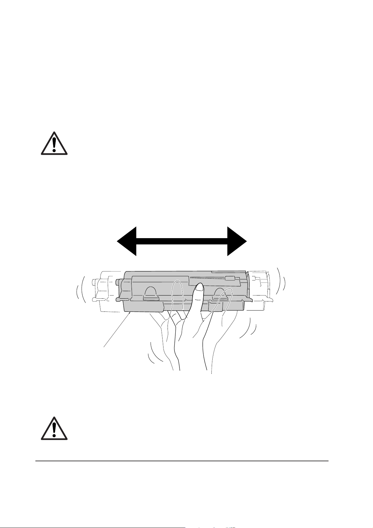
To loosen and mix the toner inside before use, with the label side down, thoroughly shake the toner
container 1 horizontally at least five times.
1
Figure 1-5-1 Toner container handling
CAUTION Do not attempt to disassemble or refill the toner container.
FS-1050
1-14
Page 23

(2) Toner container storage
The toner contained in the container is susceptible to temperature and humidity. To ensure the high
print quality, store the toner container in a place that satisfies the following environmental conditions:
Temperature: -20 to 40 °C (-4 to 104 °F)
Humidity: 15 to 90 % RH
NOTE If the toner container is removed from the printer’s developer unit, put it in a
protective bag and keep it in a dark place.
CAUTION If the printer is shipped for return, etc., do not ship it with the toner container
installed. Otherwise, toner may leak and contamination may result in the
printer.
1-15
FS-1050
Page 24

Chapter 2
Installation/Operation
Page 25

Chapter 2 Contents
2-1 Unpacking......................................................................................................................................... 2-3
2-1-1 Unpacking and inspection ......................................................................................................... 2-3
2-2 Installing the printer ........................................................................................................................ 2-4
2-2-1 Installing the toner container ..................................................................................................... 2-4
2-2-2 Expanding memory .................................................................................................................... 2-8
(1) Minimum memory requirements .......................................................................................... 2-8
(2) DIMM specifications ............................................................................................................ 2-8
(3) Notes on handling DIMM ..................................................................................................... 2-9
(4) Installing the DIMM ............................................................................................................ 2-10
(5) Testing the expansion memory ........................................................................................... 2-11
(5) Installing the memory card (CompactFlash) ...................................................................... 2-12
(6) Installing the network interface card .................................................................................. 2-14
2-3 Using the operator panel............................................................................................................... 2-15
2-3-1 Operator panel ......................................................................................................................... 2-15
(1) LED Indicators ................................................................................................................... 2-15
(2) keys ................................................................................................................................... 2-16
(3) LCD message display ....................................................................................................... 2-17
Interface indicator ................................................................................................................... 2-18
Paper size indicator ................................................................................................................ 2-18
2-3-2 Menu selection system ............................................................................................................ 2-19
(1) Menu selection and sequence ........................................................................................... 2-19
Page 26
2-1 Unpacking
2-1-1 Unpacking and inspection
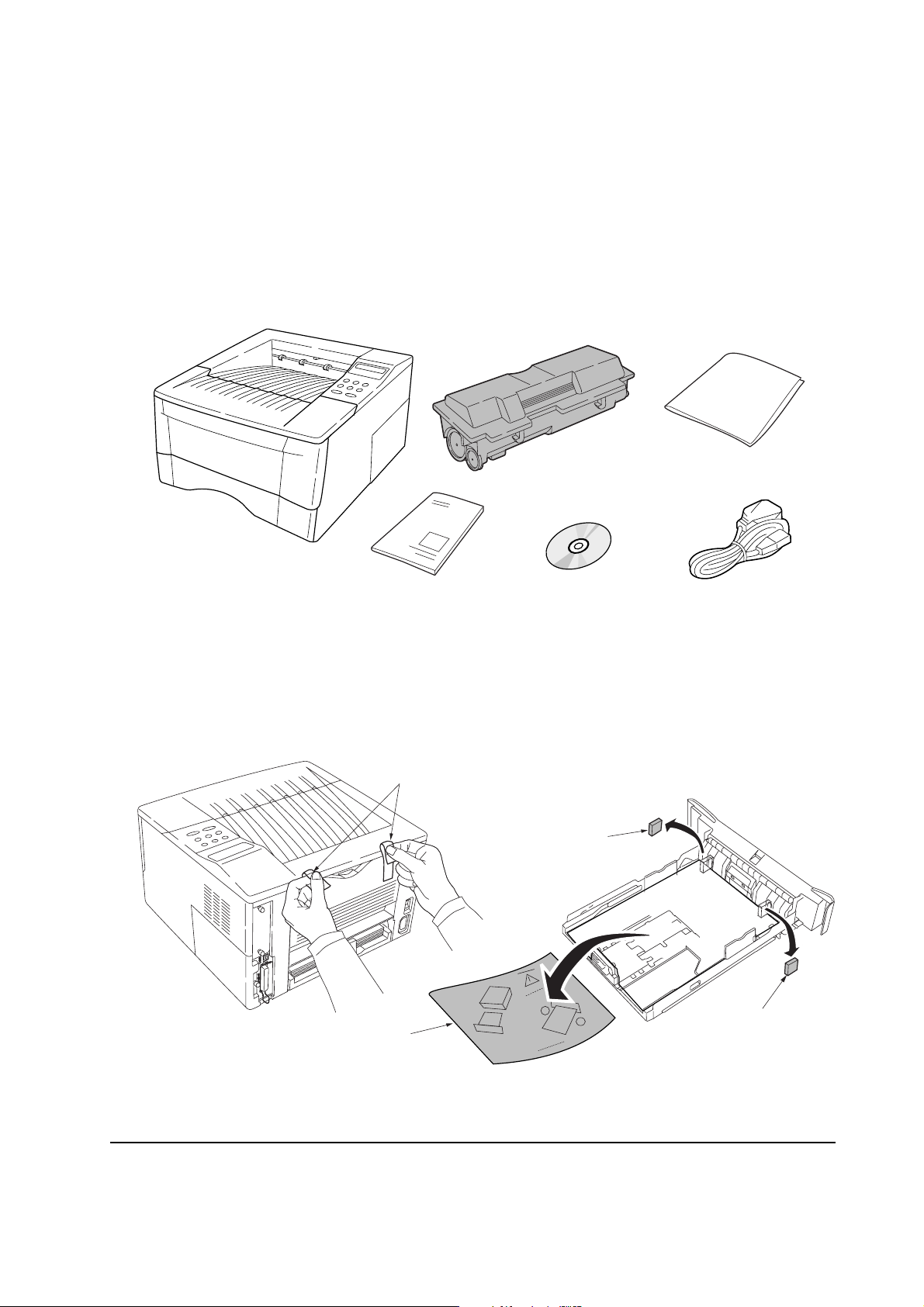
The package should contain the printer and the accessories as shown in the figure below. Remove
the printer and all the accessories from the package. For unpacking, place the box containing the
printer on a flat, stable surface. Remove the manuals, toner kit, and other items located on top of the
spacer and remove the spacer. Carefully remove the printer.
Cleaning cloth
Power cord
Printer
Installation guide
Toner container (TK-17)
Kyocera Mita digital library
CD-ROM
Figure 2-1-1 Unpacking (1)
Remove the tape on the rear side of the printer, and remove the two spacers and the printed notice
from the paper cassette.
Tapes
Spacer
Printed notice
Figure 2-1-2 Unpacking (2)
2-3
Spacer
FS-1050
Page 27
2-2 Installing the printer
Installing the printer requires several steps. Proceed as follows in sequence. If the option paper
feeder is used with the printer, begin installation with connecting the printer and the paper feeder.
For details, refer to the optional Paper feeder’s Service Manual.
2-2-1 Installing the toner container
1. Open the top cover all the way.
2. Confirm that the lock lever #1 1 is in the release (forward) position. If not, pull it forward until
it is in the release position.
1
Figure 2-2-1 Confirming the lock lever #1
FS-1050
2-4
Page 28
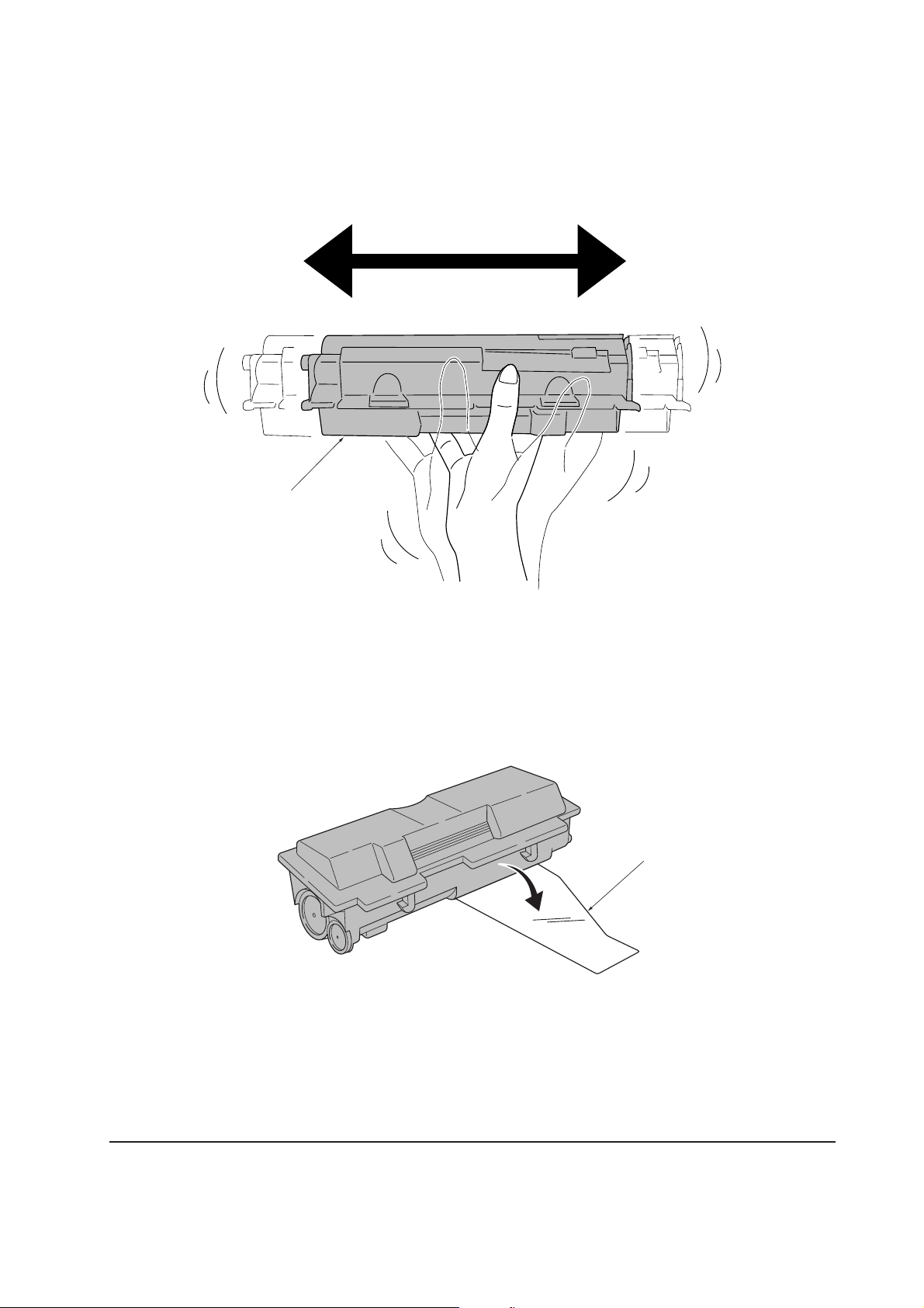
3. Take the toner container 2 from the bag. Hold it with the protective seal 3 (orange-colored)
facing up. Shake the toner container 2 horizontally at least five times. This ensures that the
toner is evenly distributed inside.
2
Figure 2-2-2 Shaking the toner container
4. Carefully remove the protective seal 3.
Figure 2-2-3 Removing the protective seal
3
2-5
FS-1050
Page 29
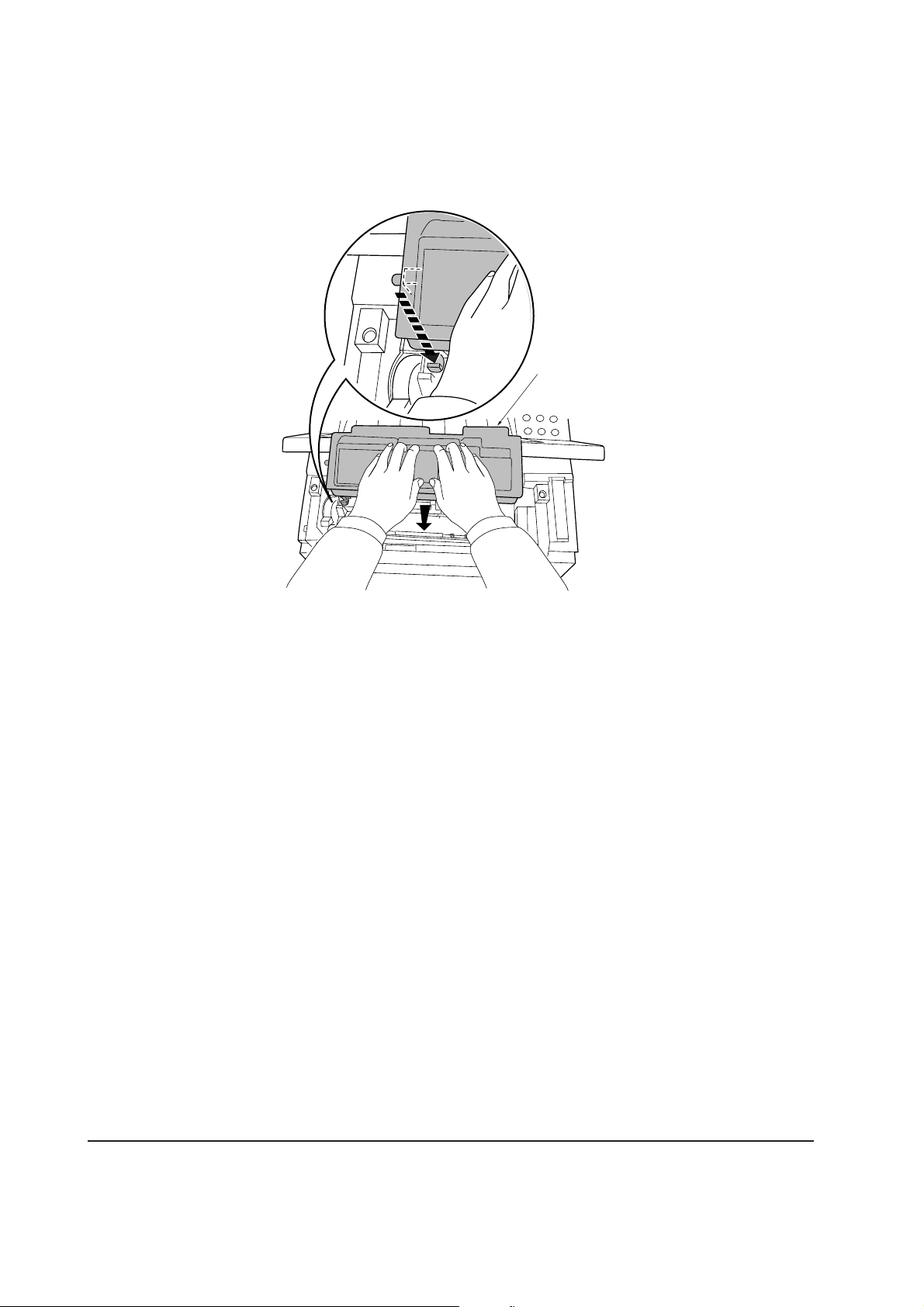
5. Install the toner container 2 into the printer.
6. Push firmly on the top of the toner container 2 at the positions marked [PUSH HERE].
2
Figure 2-2-4 Installing the toner container
FS-1050
2-6
Page 30
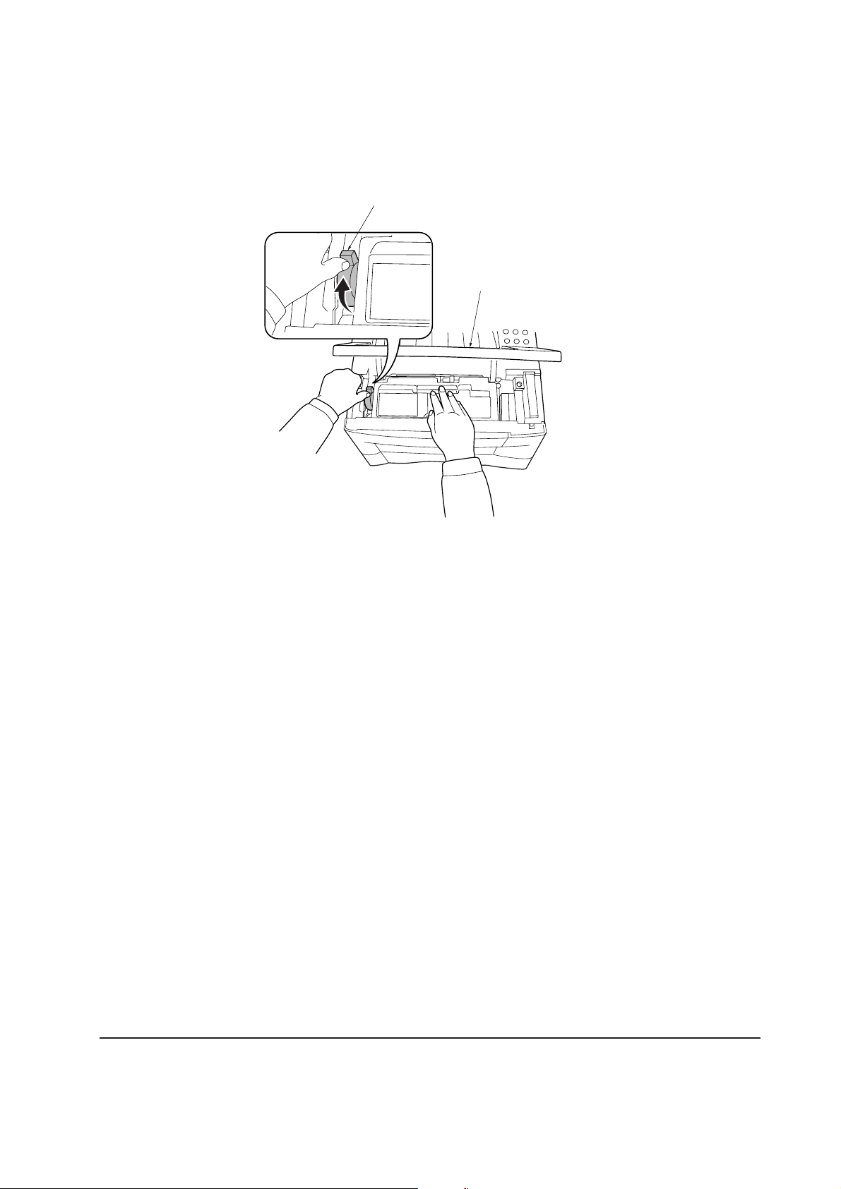
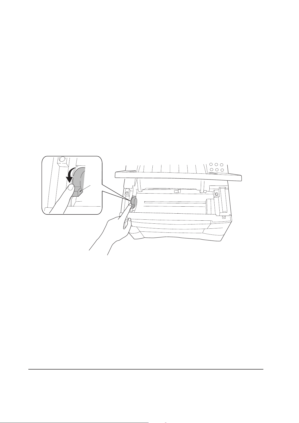
7. Push the lock lever #1 1 to the lock position.
8. Close the top cover 4.
1
LOCK
UNLOCK
LOCK
UNLOCK
4
Figure- 2-2-5 Locking the toner container
NOTE The printer is shipped from the factory with no toner supplied in its developer
(Process unit). When the printer is first switched on after the toner container is
installed in the manner above, there will be a delay of several minutes before
the printer gets ready to print a job.
This delay is necessary for the printer to fill the developer reservoir with a
sufficient amount of toner to continuously support a print job. The period of
time is approximately 15 minutes.
If the toner low or replace toner indication does not go off after installing the
new toner container, take the toner container out once, shake it well, then
install again.
2-7
FS-1050
Page 31

2-2-2 Expanding memory
The FS-1050 printer comes standard equipped with 16 MB of main memory on the main board.
Printer memory can be expanded to up to the maximum 144 MB (16 + 128 MB).
(1) Minimum memory requirements
Refer to the table below for minimum memory requirements in various environments.
Resolution
Printing environment (Emulation) 300 dpi 600 dpi
HP LaserJet 5P (factory setting) 2 MB 2 MB
HP LaserJet 5P with resource protection - 10 MB
(2) DIMM specifications
Memory size in MB 16, 32, 64, 128 MB
Number of pins 100 pins
Access speed 66 MHz
Parity None
Bus width 32 bits
FS-1050
2-8
Page 32

(3) Notes on handling DIMM
Before proceeding to install DIMM, read the following notes for handling the main board and
DIMMs:
• Protect the electronics by taking these precautions:
• Before touching a DIMM, touch a water pipe or other large metal object to discharge yourself
of static electricity. While doing the work, it is recommended that you wear an antistatic wrist
strap.
• Touch the main board and DIMM only by the edges, not in the middle.
Figure 2-2-6 Handling DIMM
2-9
FS-1050
Page 33

(4) Installing the DIMM
The main board of the printer is equipped with one socket for memory expansion. Expansion memory
is available in the form of DIMM (Dual In-line Memory Module).
CAUTION Take precautions that no foreign substances such as metal chips or liquid get
inside the printer during the installation process. Operation of the printer during
the presence of a foreign substance may lead to fire or electric shock.
WARNING Turn the printer’s power switch off. Unplug the printer’s power cable and
disconnect the printer from the computer or the network.
Remove the side cover 1 as shown in the figure below.
Step 1
Step 2
Remove
one screw.
1
1
Figure 2-2-7 Removing side cover
FS-1050
2-10
Page 34

Open the clips 2 on both ends of the DIMM socket 3. Insert the DIMM 4 into the DIMM socket
3 so that the notches on the DIMM align with the corresponding protrusions in the slot. Close the
clips 5 on the DIMM slot to secure the DIMM.
2
Step 1
4
2
5
Step 2
5
3
Figure 2-2-8 Inserting the DIMM
(5) Testing the expansion memory
After installing DIMM in the printer, test the printer to see if the installation has been successful. To
test the expansion memory, turn printer power on and print a status page. If the installation has been
successful, the Available Memory item of the status page will show the expanded memory size
corresponding to the amount of memory added.
FS-1050
2-11
Page 35

(5) Installing the memory card (CompactFlash)
The main board of the printer is equipped with one slot for memory card.
CAUTION Take precautions that no foreign substances such as metal chips or liquid get
inside the printer during the installation process. Operation of the printer during
the presence of a foreign substance may lead to fire or electric shock.
WARNING Turn the printer’s power switch off. Unplug the printer’s power cable and
disconnect the printer from the computer or the network. Never insert or
remove a memory card while the printer power is ON.
Failure to turn the power switch OFF will immediately halt the printer with a
Memory card err20 message (this message may not always appear).
It also could result in any damage to the printer’s electronic parts or the
memory card. Turn the power switch ON again to restart the printer.
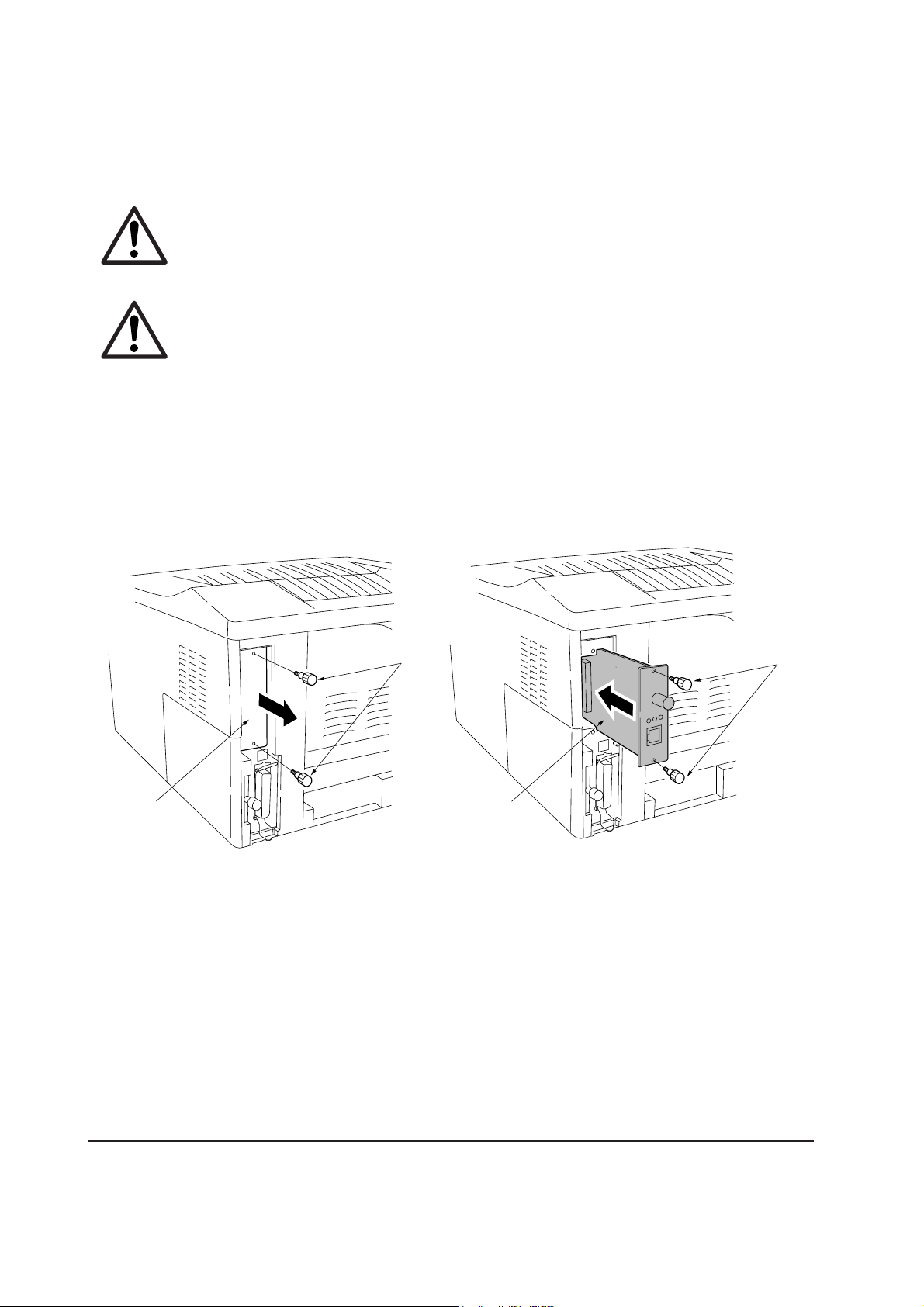
Remove the two screws 1 from the option interface slot cover 2 and remove the slot cover (or
network interface card 3 or the serial Interface board) .
2
1
3
Figure 2-2-9 Removing the option interface slot cover
1
FS-1050
2-12
Page 36
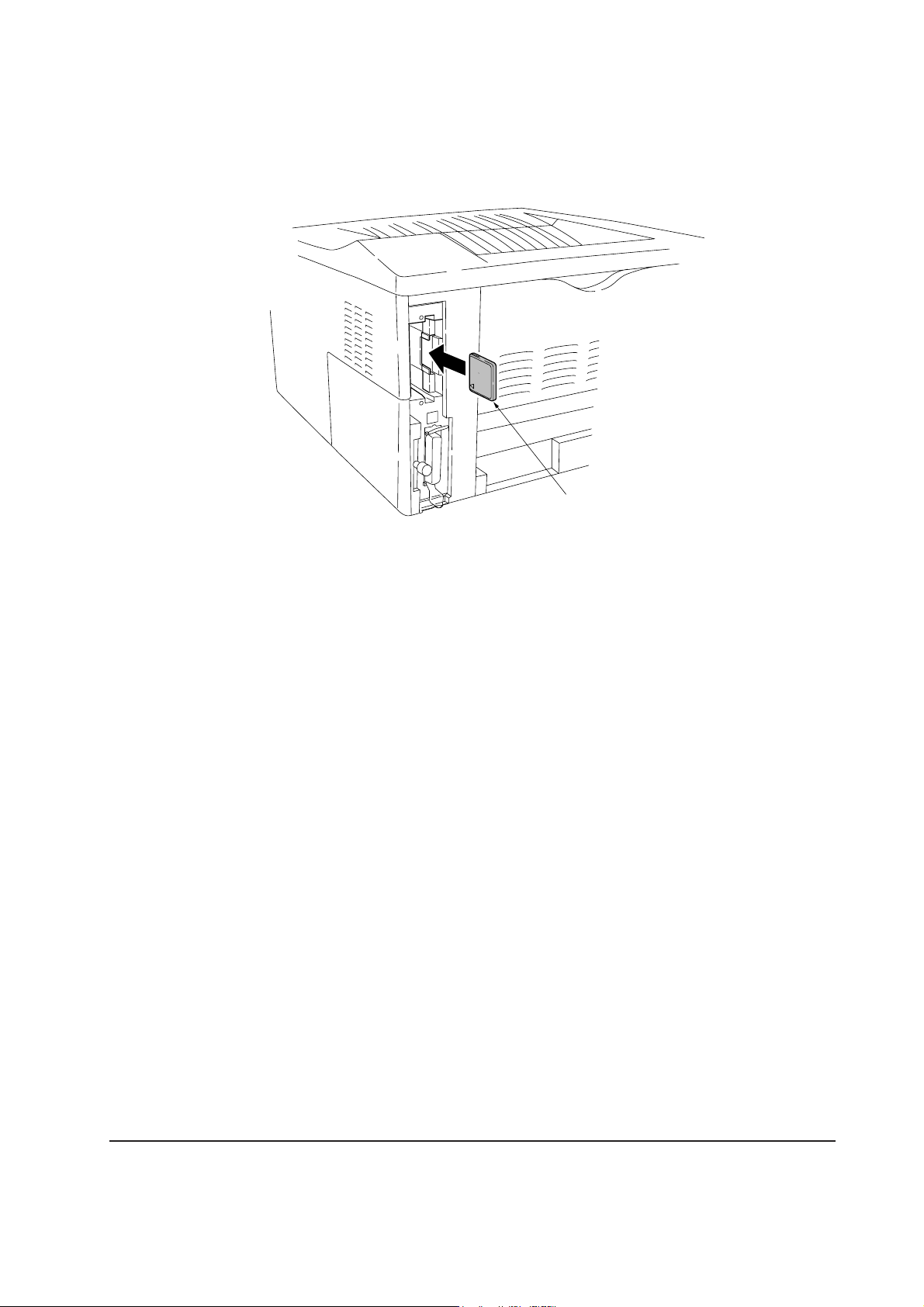
Insert the memory card 4 in the slot. Insert as shown in the figure. Push it in all the way. Close and
secure the slot cover (or network interface card or the serial Interface board) .
4
Figure 2-2-10 installing the memory card
2-13
FS-1050
Page 37
(6) Installing the network interface card
If the serial interface board kit is installed, remove it to use the network interface card.
CAUTION Take precautions that no foreign substances such as metal chips or liquid get
inside the printer during the installation process. Operation of the printer during
the presence of a foreign substance may lead to fire or electric shock.
WARNING Turn the printer’s power switch off. Unplug the printer’s power cable and
disconnect the printer from the computer or the network. Never insert or
remove a network interface card while the printer power is ON.
Remove the two screws 1 from the option interface slot cover 2 and remove the slot cover ( or
the serial Interface board) .Insert the network interface card 3 in the slot. Insert as shown in the
figure. Push it in all the way. Secure the network interface card by using two screws 1.
2
1
3
Figure 2-2-11 installing the memory card
1
FS-1050
2-14
Page 38

2-3 Using the operator panel
This section provides explanation on how to use the printer’s operator panel for basic operation.
For details, refer to the printer’s User’s Manual.
2-3-1 Operator panel
The printer’s operator panel has the following LED indicators, keys, and LCD message display.
Note that adjustments to the printer parameters made using these keys may be overridden by those
made from within the application software.
INTERFACE SIZE TYPE
READY
1
DATA ATTENTION
9
7
6
MENU ENTER
5
CANCEL
GO
Figure 2-3-1 Operator panel
(1) LED Indicators
LED Indicator Condition Description
1 READY indicator
Flashing
Lit
Indicates errors that you can correct himself or herself.
Indicates that the printer is online and ready.
@
3
2
0
8
!
4
2 DATA indicator
Off
Flashing
Lit
Off
Indicates that the printer is offline. The printer can
receive data, but will not print it. The indicator can also
signal that printing has been manually or automatically
stopped due to an error.
Indicates a data transfer in process.
Indicates either that data is being processed, or that data
is being written to the memory card.
Indicates that the printer is idle.
FS-1050
2-15
Page 39

LED Indicator Condition Description
3 ATTENTION
indicator
Flashing
Lit
Indicates that paper has run out, that memory is
insufficient, that toner is low, or other warning messages.
Indicates common errors (such as controller errors),
when mechanical maintenance is needed or indicates a
problem that requires a call to the service center.
Off
Indicates the printer is operating normally.
(2) keys
Key Function
4 GO key
• Switches the printer online and offline (even offline, the printer can
receive data).
• Cancels specific errors.
5 CANCEL key
• Cancels a printing job.
To cancel, proceed as follows:
1. Make sure if Processing appears on the message display.
6 MENU key
2. Press the CANCEL key.
3. Print Cancel? appears on the message display and then interface to be
canceled.
Parallel Serial (appears only when an optional serial interface is present)
Option (appears only when an optional network interface card is
installed)
Press the CANCEL key again if you wish to stop the cancellation of
printing.
4. Select the interface to cancel using the or key and then press the ENTER
key.
Printing from the selected interface will stop. Cancelling data appears
in the message display and printing stops after the current page is
printed.
• Resets numeric values or cancels a setting procedures.
• When pressed during mode selection, it ends the setting and the printer
returns to the Ready condition.
• Used to select the emulation, font, character code set; to read a memory
FS-1050
card; and more.
2-16
Page 40

Key Function
7 Key
Used to access desired items or input numeric values. In some control
procedures, the < and > keys are used to access or exit submenu items.
8 key
Used to access desired items or input numeric values. In some control
procedures, the < and > keys are used to access or exit submenu items.
9 < key
0 > key
! ENTER key
Used as the < key in mode selection.
Used as the > key in the mode selection function.
Confirms numeric values and other selections.
(3) LCD message display
The LCD message display @ gives information in the form of short messages. The eight messages
listed below are displayed during normal warm-up and printing. Other messages appear when the
printer needs the operator’s attention as explained in Chapter 6 Troubleshooting.
Message Meaning
Self test
Please wait
The printer is self-testing after power-up.
Please wait The printer is warming up and is not ready.
Ready
Processing
Sleeping
Cancelling data
Waiting
FormFeed TimeOut
The printer is ready to print.
The printer is receiving data, generating graphics, reading a
memory card or printing.
The printer is in Sleep mode. The printer wakes from Sleep
mode whenever a key on the operator panel is pressed, the
cover is opened or closed, or data is received. The printer
then warms up and goes online. The time that the printer takes
to enter Sleep mode depends on the Sleep Timer setting.
Jobs inside the printer are being cancelled. To cancel a job,
see the table on page 1-5.
The printer is waiting for the end-of-job command before
printing the last page. Pressing the GO key allows you to
obtain the last page immediately.
The printer is printing the last page after a waiting period.
2-17
FS-1050
Page 41

Interface indicator
The LCD message display also shows the interface that is currently used in the from of the following abbreviations:
Message Meaning
PAR Standard bidirectional parallel interface
USB Standard USB interface
SER Optional serial interface (RS-232C)
OPT Optional network interface card
--- No interface is currently used.
Each interface has a time-out time of 30 seconds during which the other interface should wait to receive a print
job. Even a print job has been complete on the interface, you should wait for this period until the other
interface begins printing the job
.
Paper size indicator
The LCD message display also provides information about the paper size of the paper cassette. While the
printer is Processing data to print, the paper size indicator switches to indicate the paper size selected by the
application software. The following abbreviations are used to indicate paper sizes.
Message Paper size
A4 ISO A4 (21 × 29.7 cm)
DL ISO DL (11 × 22 cm) *
A5 ISO A5 (14.8 × 21 cm)
C5 ISO C5 (16.2 × 22.9 cm) *
A6 ISO A6 (10.5 × 14.8 cm) *
b5 ISO B5 (17.6 × 25 cm) *
B5 JIS B5 (18.2 × 25.6 cm)
EX Executive (7-1/4 × 10-1/2 inches) *
B6 JIS B6 (12.8 × 18.2 cm) *
FS-1050
#6 Commercial 6-3/4 (3-5/8 × 6-1/2 inches) *
LT Letter (8-1/2 × 11 inches)
#9 Commercial 9 (3-7/8 × 8-7/8 inches) *
LG Legal (8-1/2 × 14 inches)
HA Japanese postcard (10 × 14.8 cm) *
MO Monarch (3-7/8 × 7-1/2 inches) *
OH Return postcard (20 × 14.8 cm) *
BU Business (4-1/8 inches) *
CU Custom size (14.8 × 21 cm to 21.6 × 35.6 cm)
* with only the MP tray feeding
2-18
Page 42
2-3-2 Menu selection system
The MENU key on the operator panel allows you to use the menu selection system to set or change
the printer environment such as the paper source, emulation, etc. Settings can be made when Ready
is indicated on the printer message display. The printer obeys the most recently received printer
settings sent from the application software, or from the printer driver, which take priority over
operator panel settings.
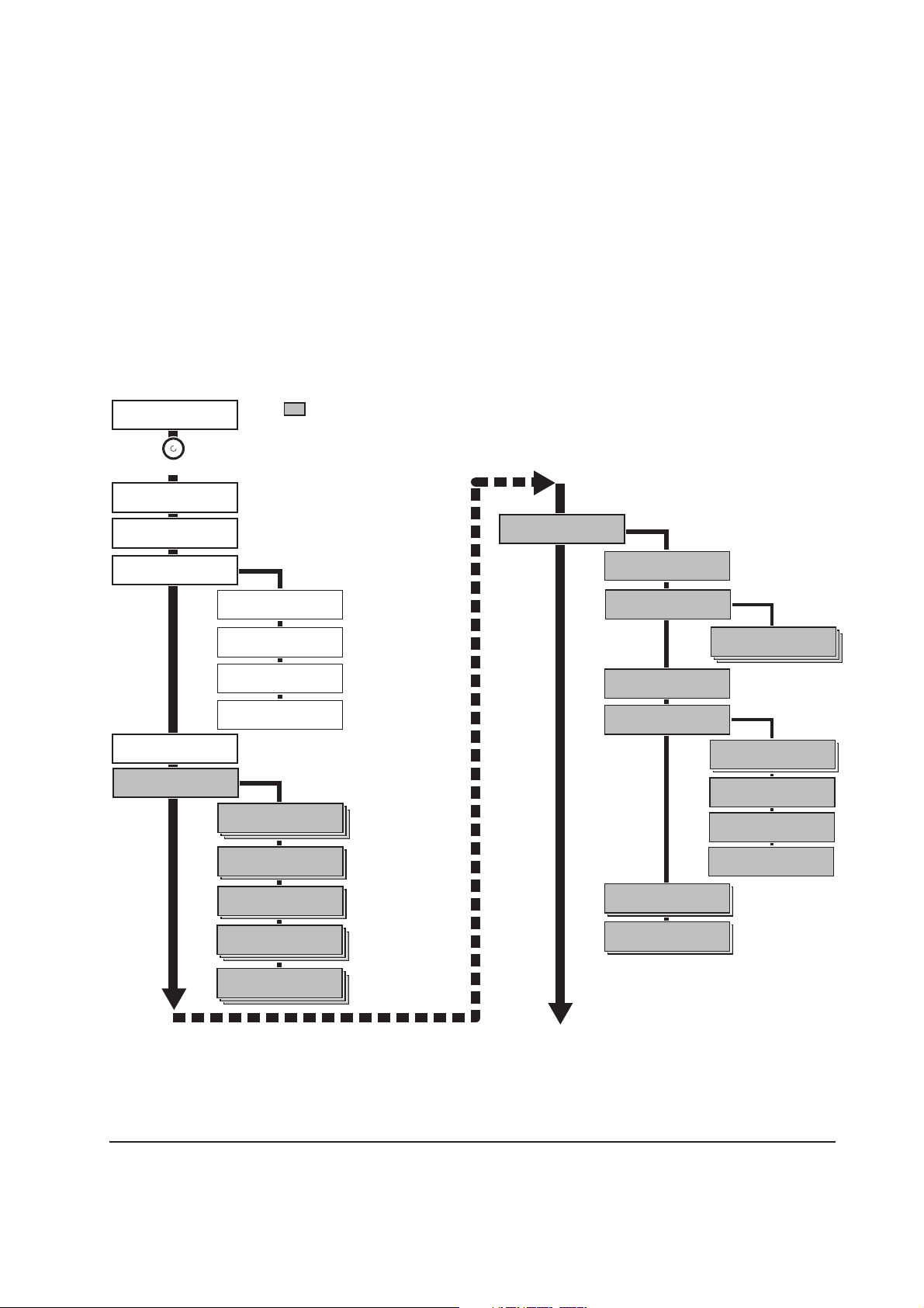
(1) Menu selection and sequence
The following is the hierarchy diagram of the menu selection system of the printer.
Ready
PAR A4
MENU
Print
Menu Map
Print
Status Page
Inter face >
Parallel
>Parallel I/F
Nibble (high)
>Parallel I/F
Auto
>Parallel I/F
Normal
>Parallel I/F
High Speed
Inter face >
USB
Interface >
Serial
>Bau rate
9600
>Data Bits
8
>Stop Bits
1
>Parity
None
These items will not
show unless the printer
is installed with the
applicable option unit.
Interface >
Option
>NetWare
Off
>NetWare >
On
>>NetWare Frame
Auto
>TCP/IP
Off
>TCP/IP >
On
>>DHCP
On
>>IP Address
000.000.000.000
>>Subnet Mask
000.000.000.000
>>Gateway
000.000.000.000
>Ether Talk
Off
>Opt. StatusPage
Off
>Protocol
DTR (pos.)&XON
Continued on next page.
FS-1050
2-19
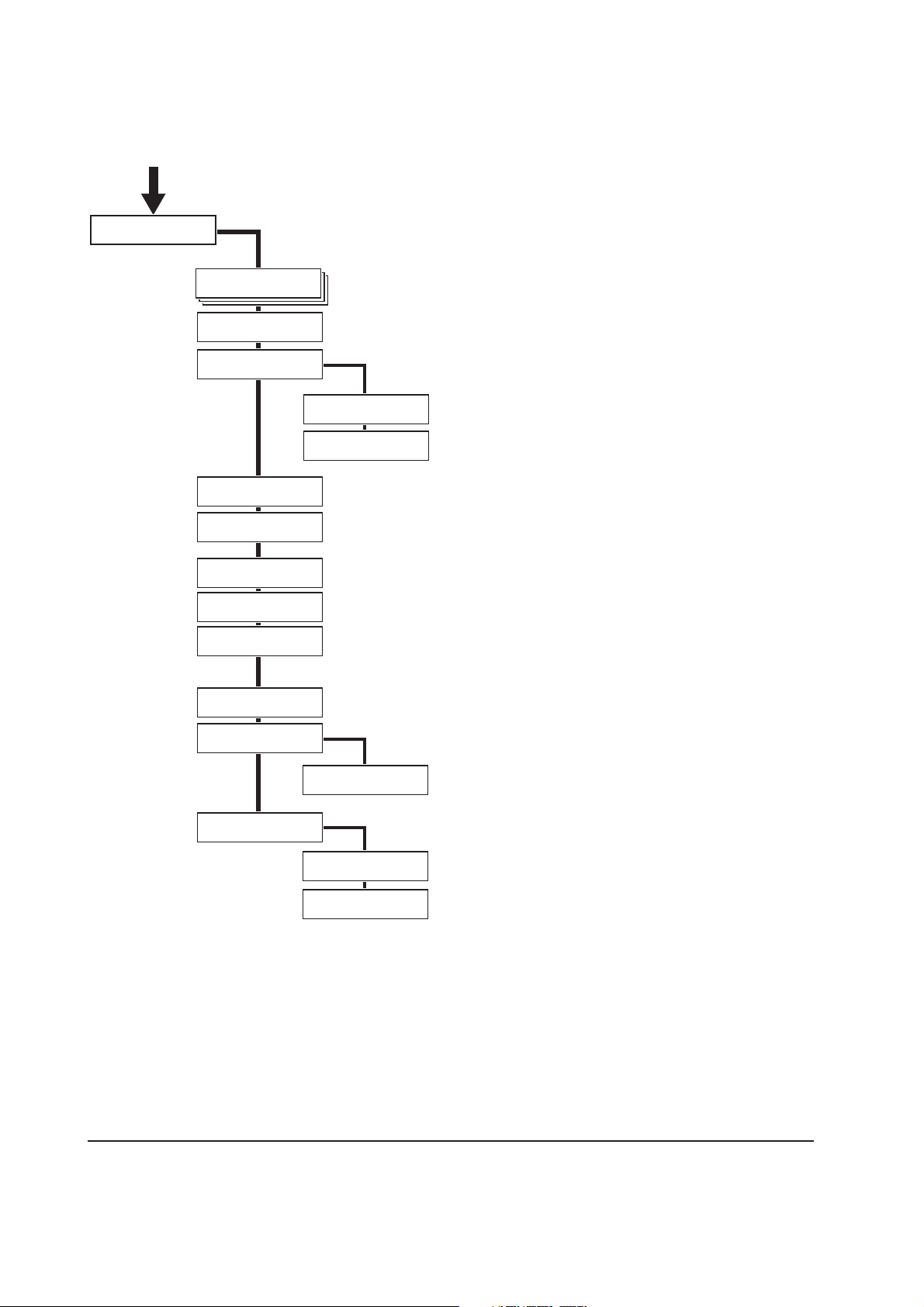
Page 43

Emulation >
PCL 6
>Code set
ISO-6 ASCII
Emulation >
KPDL
>Print KPDL errs
Off
>Print KPDL errs
On
Emulation >
KPDL (AUTO)
>Alt. Emulation
PCL 6
>Print KPDL errs
Off
>Print KPDL errs
On
Emulation >
IBM Proprinter
Emulation >
Line printer
Emulation >
DIABLO 630
Emulation >
EPSON LQ-850
Font >
Internal
>Font Select >
Internal
> I000
>Courier
Regular
>Courier
Dark
>Letter Gothic
Regular
>Letter Gothic
Dark
>Size
012.00 point(s)
>Pitch
10.00 cpi
>Font Select >
Option
> I000
>Courier
Regular
>Courier
Dark
>Letter Gothic
Regular
>Letter Gothic
Dark
>Size
012.00 point(s)
>Pitch
10.00 cpi
>Code Set
IMB PC-8
>List of
Internal Fonts
>List of
Opton Fonts
Page set >
>Copies
001
>Orientation
Portrait
>Orientation
Landscape
>Page Protect
Auto
>Page Protect
On
>LF Action
LF only
>LF Action
CR and LF
>LF Action
Ignore LF
>CR Action
LF only
>CR Action
CR and LF
>CR Action
Ignore CR
FS-1050
>Wide A4
Off
>Wide A4
On
Continued on next page.
2-20
Page 44

Print Quality >
>KIR Mode
On
>KIR Mode
Off
>Ecoprint Mode
Off
>Ecoprint Mode
On
>Resolution
Fast 1200 mode
>Resolution
300 dpi
>Resolution
600 dpi
Opt. ROM >
>Read Data
>List of
Partitions
RAM Disk Mode
On
RAM Disk Mode
Off
>Read Data
>Write Data
>Delete Data
>RAM Disk Size
Paper Handling >
>MP Tray Mode
Cassette
>MP Tray Mode
First
>MP Tray Size
A4
>MP Tray Type
Plain
>Cassette Size
A4
>Cassette Size
Custom
>>Unit
mm
>>Unit
inch
>>X Dimension
210mm
>>Y Dimension
356mm
>Cassette Type
Plain
>Feed Select
Cassette
>Feed Select
MP Tray
>Override A4/LT
Off
>Type Adjust >
Custom 1
>Reset Type
Adjust
>List of
Partitions
Memory Card >
>Read Fonts
>Read Data
>Write Data
>Delete Data
>List of
Partitions
>>Paper Weight
Normal
>>Paper Weight
Heavy (Thick)
>>Paper Weight
Light (Thin)
>>Print Density
03
LIFE Counters >
>Total Print
0123456
>New Toner
Installed
Continued on next page.
FS-1050
2-21
Page 45
Others >
>MSG language
English
>Form Feed
Time Out 030sec.
>Sleep Timer >
015 min.
>>Sleep Mode
On
>>Sleep Mode
Off
>Print HEX-DUMP
>Printer Reset
>Resource prot.
Off
>Resource prot.
Permanent
>Resource prot.
Perm / Temp
>Auto Continue
Mode Off
>Auto Continue >
Mode On
>>Auto Continue
Timer 030sec.
>Service >
>>Print
Status Page
>>Developer
FS-1050
2-22
Page 46

Chapter 3
Maintenance/Adjustments
Page 47

Chapter 3 Contents
3-1 Maintenance/Adjustments .............................................................................................................. 3-3
3-1-1 Life expectancy of modules ....................................................................................................... 3-3
3-1-2 Toner container .......................................................................................................................... 3-4
(1) When to replace the toner container ................................................................................... 3-4
(2) Notes on changing toner container ..................................................................................... 3-4
(3) Toner container replacement ............................................................................................... 3-5
(4) Toner saver mode (EcoPrint) ............................................................................................... 3-6
3-1-3 Cleaning the printer ................................................................................................................... 3-7
(1) Cleaning the registration roller ............................................................................................ 3-8
(2) Cleaning the main charger wire ........................................................................................... 3-8
3-1-4 Updating the firmware ............................................................................................................... 3-9
(1) Firmware program data format ............................................................................................ 3-9
(2) Downloading the firmware from the parallel interface ....................................................... 3-10
(3) Downloading the firmware from the memory card ............................................................. 3-12
(4) Downloading errors ........................................................................................................... 3-14
Page 48

3-1 Maintenance/Adjustments
3-1-1 Life expectancy of modules
The table below shows the nominal life expectancy for modules. Detailed part information for each
module (except toner container) can be found in Parts Catalog.
Table 3-1-1 Life expectancy of modules
Kit Module Nominal life (pages) Remarks
TK-17 Toner container 6,000 User-replaceable
PU-42 Process unit 100,000 User-replaceable
3-3
FS-1050
Page 49

3-1-2 Toner container
Assuming an average toner coverage of 5 % with EcoPrint mode turned off, the toner container
will need replacing approximately once every 6,000 printed pages.
Table 3-1-2 Toner container
Kit Life in pages
TK-17 6,000
Based on letter or A4 size paper; average print density of 5 %.
NOTE In the case of a new printer in which a toner kit has been installed for the first
time, the number of copies that can be printed will be approximately 3,000.
(1) When to replace the toner container
When the printer runs low on toner, the Toner indicator flashes on the operation panel. Be sure to
promptly replace the toner container and clean the inside of the printer when this message appears.
If the printer stops printing while the Toner indicator is lit, replace the toner container to continue
printing.
(2) Notes on changing toner container
Observe the following cautions when replacing the toner container:
• Do not attempt to disassemble the old toner container and reuse the waste toner inside.
• Keep magnetic media such as floppy disks away from the toner container.
• Be sure to clean the parts as instructed in this section at the same timing of replacing toner
container.
• Use of the toner kit TK-17 is highly recommended for the optimum operation of the printer.
FS-1050
3-4
Page 50

(3) Toner container replacement
To replace the toner container, open the top cover. Pull lock lever #1 1 to the release [UNLOCK]
position, then pull lock lever #2 2 to the release (right) position.
1
2
Figure 3-1-1 Releasing Lock levers #1 and #2
Gently remove the old toner container 3.
Figure 3-1-2 Removing the old toner container
3
3-5
FS-1050
Page 51

Put it in the supplied plastic bag 4 and dispose of it.
4
Figure 3-1-3 Disposal of the old toner container
NOTE Although the toner container is made from non-harmful, flammable material,
be sure to dispose of it according to laws and regulations.
Proceed with the instructions provided in chapter 2, Installing the toner container on page 2-4 to
complete installation of the new toner container.
(4) Toner saver mode (
EcoPrint
)
The EcoPrint enables to reduce the amount of toner consumed on the page so as to save printing
costs by drastically extending the toner container life. EcoPrint mode is factory-set to off and
turned on by using the operator panel (MENU) For details refer to the printer’s User’s Manual.
FS-1050
3-6
Page 52
3-1-3 Cleaning the printer
1
2
3
To avoid print quality problems, the following printer parts must be cleaned with every toner container
replacement.
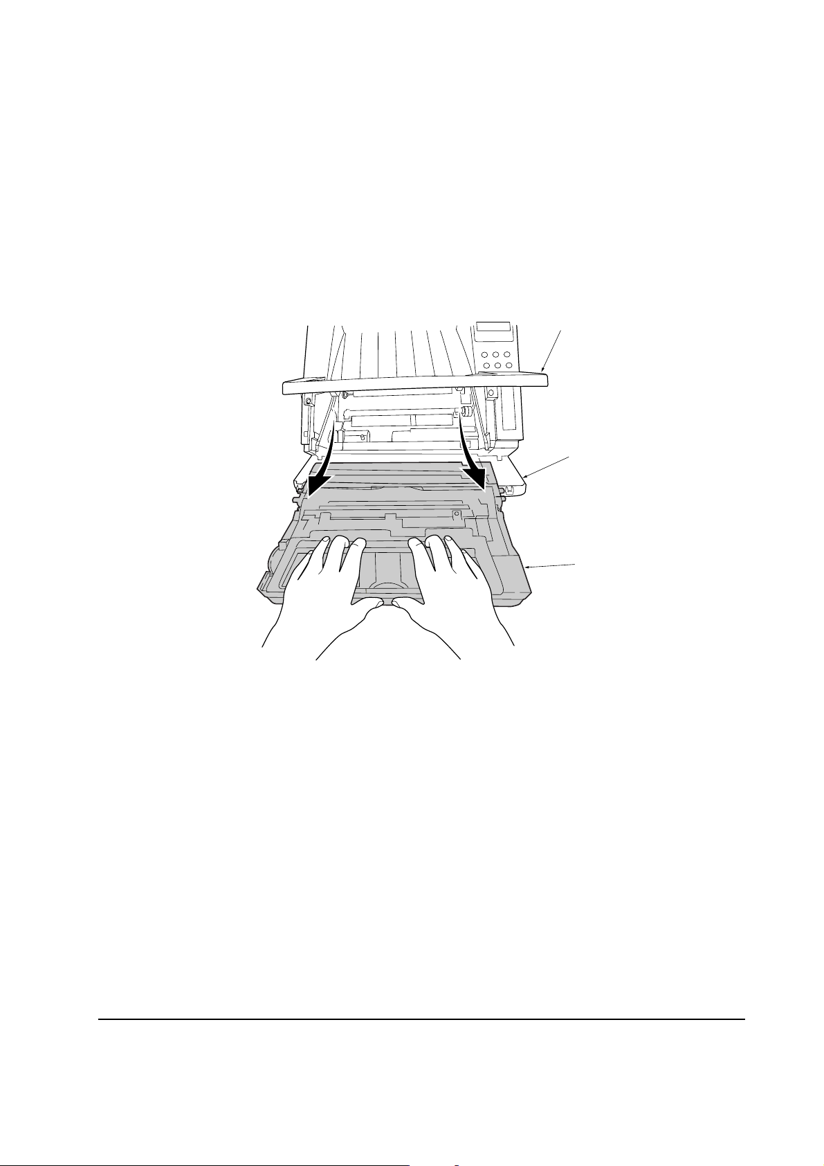
To clean the printer, first, remove the process unit from the printer.
Open the top cover 1 and front cover 2. Lift the process unit 3 together with the toner container
out of the printer.
Figure 3-1-4 Removing the process unit
NOTE The drum in the process unit is sensitive to light. Never expose the drum even
to normal office lighting (500 lux) for more than five minutes.
FS-1050
3-7
Page 53

(1) Cleaning the registration roller
Use the supplied wiper cloth 1 to clean dust and dirt away from the registration roller 2 (metal).
2
1
Figure 3-1-5 Cleaning the registration roller
(2) Cleaning the main charger wire
Slide the charger cleaner knob (green colored) back and forth 2 to 3 times, then return it to its
[CLEANER HOME POSITION].
1
1
Figure 3-1-6 Cleaning the main charger wire
After cleaning is done, install the process unit in the printer, using the reverse manner as above.
Close the front cover and top cover.
FS-1050
3-8
Page 54

3-1-4 Updating the firmware
Updating the system (controller) firmware is possible by downloading the firmware through the
parallel interface or through the memory card (CompactFlash). These firmware programs are directly
overwritten in the system DIMM [board KP-893] (Flash ROM type only) on the main board.
The operator panel message in different languages can also be downloaded through the parallel
interface or through the memory card (CompactFlash).
(1) Firmware program data format
Kyocera supplies the following types of data for updating firmware of the different purposes:
• System firmware
The data to be downloaded are supplied in the following format:
System firmware file name example
A93K8000.bcmp
compression
Boot program is included.
Version code: Version 80.00
ID code for Kyocera
Machine code: FS-1050 (A93)
Figure 3-1-9 Firmware program data format
3-9
FS-1050
Page 55

(2) Downloading the firmware from the parallel interface
This section explains how to download firmware data from the parallel interface. The printer system
can automatically recognize whether the data to be overwritten is for controller firmware.
CAUTION Downloading the firmware takes several minutes. Do not turn power off during
downloading.
NOTE MS-DOS is required for a downloading from the parallel interface. The
computer must be connected to the printer with a parallel cable.
1 Turn power switch on.
2 At the DOS prompt, send the command to the printer that engages the printer in the supervisor
mode.
3 Copy the firmware data to the printer. (See the flow chart below)
[System firmware ex. A93K8000.bcmp]
Start
1
Power switch: On
Message display
Self test
Ready
2
>ECHO !R!UPGR'SYS';EXIT;>PRN
>Supervisor mode
Parallel waiting
3
>COPY/B A938000.bcmp PRN
PC display
FS-1050
To the next page
3-10
Page 56

4 Supervisor mode. The parallel interface is waiting for the firmware data.
5 Receiving the firmware data.
6 The system DIMM or flash ROM is overwritten with the new firmware data.
7 Firmware downloading is finished. (When more than one data are down loaded, the data display
can be changed by pressing any key.)
8 Turn power switch off and on.
9 Check the that printer gets Ready.
From the previous page
: Shows only included
firmeware of boot program
(".bcmp" extension file).
A: u= Extracting
W= Writing
V= Verifiying
B: Version
C: Year/Month/Day
D: [Checksum]
E: Means more than one data
4
Supervisor mode
parallel waiting
Message display
5
data receiving
>>>>>>>>>>>
6
BootROM
erase&write
DIMM erasing #??
DIMM writing
<<<<<<<<<<u
B
7
80.00S
01/08/07[1234] 2
CD
8
Power switch: Off/On
9
Ready
A
E
End
Confirm that the status page shows the new system firmware version (See Appendix B on page B-
4). If the message display indicates download error, refer to section Downloading errors on page 3-
14.
FS-1050
3-11
Page 57

(3) Downloading the firmware from the memory card
To download data written in a memory card (CompactFlash) to the printer, proceed as explained in
this section.
CAUTION Downloading firmware takes several minutes. Do not turn power off during
downloading. If downloading is interrupted by an accidental power failure,
etc., the system DIMM may have to be replaced.
NOTE The firmware program data must be stored to the root directory of the memory
card (CompactFlash).
1 Turn power switch off.
2 Remove the two screws and then remove the slot cover. Insert the memory card in the printer’s
memory card slot.
3 Turn power switch on.
4 The printer is automatically engaged in the supervisor mode.
Start
2
Power switch: Off
1
3
Power switch: On
Self test
Memory
card
Message display
FS-1050
To the next page
3-12
Page 58

5 Data are transferred to the RAM on the main board.
6 The system DIMM or Flash ROM is overwritten with the new firmware data.
7 Firmware download is finished. (When more than one data are down loaded, the data display
can be changed by pressing any key.
8 Turn power switch off.
9 Remove the memory card and then secure the slot cover by using two screw.
0 Turn power switch on.
! Check the printer gets Ready.
From the previous page
4
Supervisor mode
Message display
5
Supervisor mode
CF-CARD Reading
6
BootROM
erase&write
DIMM erasing #??
DIMM writing
<<<<<<<<<<u
B
7
80.00S
01/08/07[1234] 2
CD
Powe r switch: Off
8
: Shows only included firmeware of boot program
(".bcmp" extension file).
A: u= Extracting
W= Writing
V= Verifiying
B: Version
C: Ye ar/Month/Day
D: [Checksum]
E: Means more than one data
A
E
9
0
Powe r switch: On
!
Ready
Memory
card
End
Confirm that the status page shows the new system firmware version (See Appendix B on page B-
4). If the message display indicates download error, refer to section Downloading errors on page 3-
14.
FS-1050
3-13
Page 59

(4) Downloading errors
The following messages are indicated on the message display when an error occurred during
downloading the firmware data.
Error message Description Corrective action
download header
error [##]
##: Error code 20 to 26.
system download
error [##]
##: Error code 40 to 59.
receive
error [##]
##: Error code 80 or 81.
Deficit of the file header
Deficit of the data header
File checksum error
Data checksum error
File header version error
Data header version error
Incompatibility of firmware and
system DIMM board
Defective system DIMM board
Improper connection of parallel cable
between PC and printer
Defective parallel cable
Obtain the correct firmware.
Confirm whether the firmware
is applicable to this printer.
Replace the system DIMM
board.
Check the contact between PC
and the printer’s interface
connector.
Replace the parallel cable.
If the corrective action above does not solve the problem, replace engine board (KP-882). See page
5-11.
FS-1050
3-14
Page 60

Chapter 4
Operation Overview
Page 61

Chapter 4 Contents
4-1 Electrophotographic system .......................................................................................................... 4-3
4-1-1 Electrophotographic cycle ......................................................................................................... 4-3
Process unit mechanism ........................................................................................................... 4-4
(1) Main charging ...................................................................................................................... 4-5
Photo conductive drum ............................................................................................................. 4-5
Charging the drum .................................................................................................................... 4-6
(2) Exposure ............................................................................................................................. 4-7
Laser scanner unit .................................................................................................................... 4-8
Drum surface potential .............................................................................................................. 4-9
(3) Development ..................................................................................................................... 4-10
(4) Transfer ..............................................................................................................................4-11
(5) Fusing ................................................................................................................................ 4-12
Fuser unit mechanism ............................................................................................................ 4-13
(6) Cleaning ............................................................................................................................ 4-14
4-2 Paper feeding system .................................................................................................................... 4-15
4-2-1 Paper feed control ................................................................................................................... 4-16
Paper feeding mechanism ...................................................................................................... 4-17
4-3 Electrical control system .............................................................................................................. 4-18
4-3-1 Electrical parts layout .............................................................................................................. 4-18
4-3-2 Operation of circuit boards ..................................................................................................... 4-19
(1) Main board ........................................................................................................................ 4-19
(2) Engine board ..................................................................................................................... 4-20
Eraser lamp control circuit ...................................................................................................... 4-21
Polygon motor control circuit .................................................................................................. 4-25
(3) Power supply board ........................................................................................................... 4-26
(4) Bias board ......................................................................................................................... 4-27
(5) High voltage board ............................................................................................................ 4-28
Interlock switch ....................................................................................................................... 4-29
Page 62

4-1 Electrophotographic system
Electrophotography is the technology used in laser printing which transfer data representing texts
or graphics objects into a visible image which is developed on the photosensitive drum, finally
fusing on paper, using light beam generated by a laser diode.
This section provides technical details on the printer’s electrophotography system.
4-1-1 Electrophotographic cycle
The electrophotography system of the printer performs a cyclic action made of six steps as follows.
Each step is technically explained in the following sections.
Laser scaner unit
Process unit
1
Main charging
2
Exposure
Drum
6
Cleaning
5
Fusing
Fuser unit
4
Transfer
3
Developing
Figure 4-1-1 Electrophotographic cycle
The sections for main charging, exposure (drum), developing, and cleaning are modularized in one
Process unit PU-42.
4-3
FS-1050
Page 63
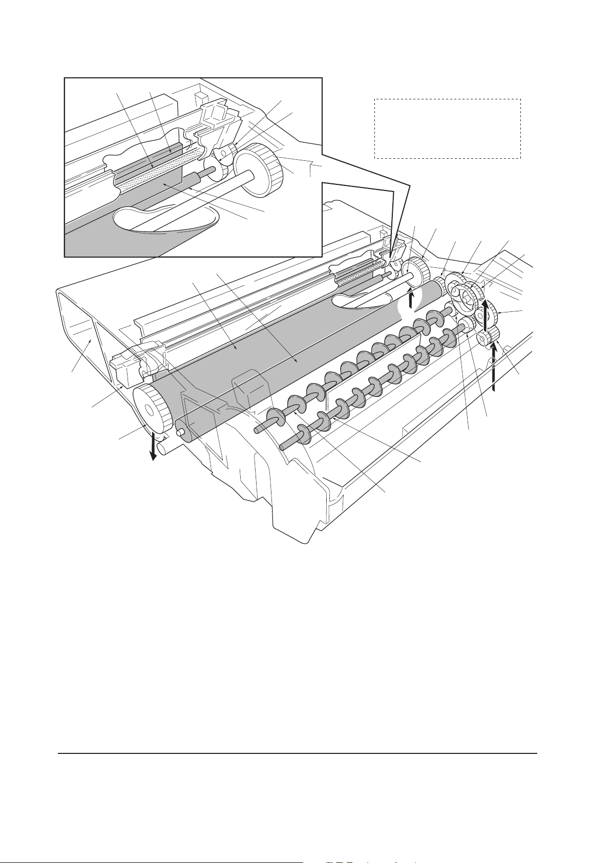
Process unit mechanism
‹
3
2
%
4
⁄
¤
)
(
Driving power train
A For drum (From main unit)
B For toner container, developing
roller, etc. (From main unit)
C For main unit (Transfer roller)
D For toner container
&
^
0
89
D
A
7
6
5
1
*
C
1 Main charger unit
2 Charger wire
3 Grid
4 Developing roller
5 Gear Z14-Z18
6 Gear Z14-Z36
7 Gear Z18-Z36
8 Free gear Z40
9 Gear Z18-Z35H
0 MAG gear Z24H
! Mixer gear Z20 B
@ Mixer gear Z20 A
# DLP screw B
$ DLP screw A
% Drum
^ Drum gear Z35H
B
!
@
#
$
& Drum shaft
* Drum gear Z36
( Sweep gear Z13
) Idle gear 18H
⁄ Cleaning blade
¤ Sweep roller
‹ Waste toner reservoir
FS-1050
Figure 4-1-2 Process unit mechanism
4-4
Page 64

(1) Main charging
Photo conductive drum
The durable layer of organic photoconductor (OPC) is coated over the aluminum cylinder base.
The OPC tend to reduce its own electrical conductance when exposed to light. After a cyclic process
of charging, exposure, and development, the electrostatic image is constituted over the OPC layer.
Since the OPC is materialized by resin, it is susceptible to damage caused by sharp edges such as a
screwdriver, etc., resulting in a print quality problem. Also, finger prints can cause deterioration of
the OPC layer, therefore, the drum (in the process unit) must be handled with care. Substances like
water, alcohol, organic solvent, etc., should be strictly avoided.
As with all other OPC drums, the exposure to a strong light source for a prolonged period can cause
a print quality problem. The limit is approximately 500 lux for less than five minutes. If the drum
(process unit) remains removed form the printer, it should be stored in a cool, dark place.
Photo conductive layer
Aluminum base cylinder
Figure 4-1-3 Photo conductive drum
4-5
FS-1050
Page 65

Charging the drum
The following shows a simplified diagram of the electrophotographic components in relation to the
engine system. Charging the drum is done by the main charger unit A.
Zener
board
KP-788
High voltage board
YC-M
Main charging output
A
B
Bias
board
MHVDR
C
Engine board
YC12-5CN2-A4
Figure 4-1-4 Charging the drum
As the drum C rotates in a “clean (neutral)” state, its photoconductive layer is given a uniform,
positive (+) corona charge dispersed by the main charger wire B.
Due to high-voltage scorotron charging, the charging wire can get contaminated by oxidization
after a long rum. Therefore, it must be cleaned periodically from time to time using the method
explained in chapter 3. Cleaning the charging wire prevents print quality problems such as black
streaks.
FS-1050
4-6
Page 66

(2) Exposure
The charged surface of the drum A is then scanned by the laser beam from the laser scanner unit
B.
B
A
Figure 4-1-5 Exposure
The laser beam (780 nm wavelength) beam is dispersed as the polygon motor (polygon mirrors)
revolves to reflect the laser beam over the drum. Various lenses and mirror are housed in the
scanner unit, adjust the diameter of the laser beam, and focalize it at the drum surface.
FS-1050
4-7
Page 67

Laser scanner unit
3
2
4
1
6
5
Diversion mirror
Figure 4-1-6 Laser scanner unit
Name Description
1 Laser diode Emits diffused, visible laser.
2 Cylindrical lens Compensates the vertical angle at which the laser beam hits a polygon
mirror segment.
3 Polygon mirror (motor) Has six mirror segments around its hexagonal circumference; each
mirror corresponding to one scanned line width on the drum when
laser beam scans on it.
4 F-theta lens The f-theta lens equalizes focusing distortion on the far ends of the
drum.
5 Sensor mirror Bends the very first shot of a laser scan towards the beam detection
sensor (6).
6 Pin photo sensor When shone by the sensor mirror above, this photo-sensor generates
a trigger signal for the engine controller to start activating the paper
feeding system.
FS-1050
4-8
Page 68

Drum surface potential
The laser beam is continually switched on and off depending on the print data. It is on for a black
(exposed) dot and off for a white (blank) dot. Since the drum surface is evenly charged, whenever
it is illuminated by the laser beam, the electrical resistance of the photoconductor is reduced and the
potential on the photoconductor is also lowered. Resulted on the drum surface is an electrostatic
image which represents the data to print. Note that the area to be printed black has the low potential,
constituting a “positively exposed” image.
Laser beam
Exposed surface potential
approximately +60 to +80 V
Charged surface potential
+400±15 V
OPC
layer
Aluminum
cylinder
Figure 4-1-7 Drum surface potential
Drum
4-9
FS-1050
Page 69

(3) Development
The latent image constituted on the drum is developed into a visible image. The developing roller
A contains a 3-pole (S-N-S) magnet core B and an aluminum cylinder rotating around the magnet
core B. Toner attracts to the developing roller A since it is powdery ink made of black resin bound
to iron particles. Doctor blade C, magnetized by magnet D, is positioned approximately 0.3 mm
above the developing roller A to constitute a smooth layer of toner in accordance with the roller
revolution.
0.3 - 0.4 mm
D
Developing
bias output
275±5 V DC
+ AC
Bias
board
YC-B
HVCLK
Engine board
YC11-5YC302-8
Magnetism
E
C
0.1 mm
A
N
S
S
N
S
B
F
Figure 4-1-8 Development
The developing roller A is applied with the AC-weighted, positive DC power source. Toner E on
the developing roller A is given a positive charge. The positively charged toner E is then attracted
to the areas of the drum F which was exposed to the laser light. (The gap between the drum F and
the developing roller A is approximately 0.3 mm.) The non-exposed areas of the drum F repel the
positively charged toner as these areas maintain the positive charge.
The developing roller A is also AC-biased to ensure contrast in yielding by compensating the
toner’s attraction and repelling action during development.
FS-1050
4-10
Page 70

(4) Transfer
The image developed by toner on the drum A is transferred onto the paper because of the electrical
attraction between the toner itself and the transfer roller B. The transfer roller is negatively biased
so that the positively charged toner is attracted onto the paper while it is pinched by the drum and
the transfer roller.
A
B
Tr ansfer bias
High voltage board
YC-T
YC1-A5
YC1-A5
YC1-A7
YC1-A8
YC1-A8
Bias
board
RTHVDR
THVDR
HVISEL
PSEL1
PSEL2
Engine board
YC11-14
YC12-2
YC11-12
YC11-9
YC11-7
Figure 4-1-9 Transfer
The nominal transfer bias is set to approximately -1.8 kV (limit) with the -6 µA current. Since the
ideal potential of the transfer bias depends on the thickness of paper, the bias is raised to approximately
-2.5 kV/-6 µA for thicker paper. On the other hand, the bias current is reduced to -1.8 kV/-6 µA for
thin paper.
4-11
FS-1050
Page 71

(5) Fusing
The toner on the paper is molten and pressed into the paper as it passes between the heat roller A
and the press roller B in the fuser unit.
A
B
Figure 4-1-10 Fusing
The heat roller has a halogen lamp inside which continuously turns on and off by the thermistor to
maintain the constant temperature onto the heat roller surface. The temperature is approximately
160 °C while the printer is idle; approximately 175 °C (Normal paper) and 185 °C (Thick paper)
while printing.
The heat roller is resin coated by florin to prevent toner from accumulating on the roller after a long
run. Care must be taken while handling the heat roller not to scratch the roller surface as doing so
may result in print problems.
The heat roller has four claws which are continuously in contact with its surface. These claws
prevent the paper on which toner has been fused from being wound around the heat roller causing
paper jam.
The pressure roller is made of the heat-resistant silicon rubber. This roller is used to strongly press
the paper towards the heat roller by means of coil springs.
The temperature of the heat roller is constantly monitored by the engine board using the thermistor
and triac. Should the temperature of the heat roller exceed the predetermined value, the thermal
cutout is activated to effectively disconnect the heater (halogen) lamp from power.
FS-1050
4-12
Page 72

Fuser unit mechanism
0
9
!
@
1
2
1 Heat roller
2 Idle gear Z34
3 Exit gear Z23
4 Idle gear Z18
8
7
5
6
5 Heat gear Z33
6 Press roller
7 Heater lamp [500±25 W]
8 Thermal cutout
9 Separator(s)
0 Thermistor
! Exit pulley(s)
@ Lower exit roller
Figure 4-1-11 Fuser unit mechanism
3
4
4-13
FS-1050
Page 73

(6) Cleaning
After the transferring process, the drum needs to be physically cleaned of toner which is residual
after the development process. The cleaning blade A is constantly pressed against the drum B and
scrapes the residual toner off to the sweep roller C. The waste toner is collected at the output end
of the sweep roller C and sent back to the toner container, into the waste toner reservoir D.
E
B
A
C
D
Figure 4-1-12 Drum cleaning and erasing static charge
After the drum B is physically cleaned, it then must be cleaned to the electrically neutral state.
This is necessary to erase any residual positive charge, ready to accept the uniform charge for the
next print process. The residual charge is canceled by exposing the drum B to the light emitted
from the eraser lamp E. This lowers the electrical conductivity of the drum surface making the
residual charge on the drum surface escape to the ground.
FS-1050
4-14
Page 74

4-2 Paper feeding system
The paper feeding system picks up paper from the cassette, MP tray, or if installed, the paper feeder
PF-17, feeds it in the printer, and delivers in the output tray. Paper is fed at the precise timing in
synchronization with data processing. The paper feeding system finally delivers the printed page to
either the face-down or face-up tray as manipulated by the user.
The figure below shows the components in the paper feeding system and the paths through which
the paper travels. The sensors, clutches, etc., are described in the following pages.
4
&
^
4
(
6
*
%
3
$
#@ 0
!
8
5
9
2
1
7
1 Cassette
2 MP tray
3 Face-down output tray
4 Face-up output tray
5 Process unit
6 Fuser unit
7 Feed roller
8 Feed pulley
9 MP feed roller
0 Lower registration roller
! Upper registration roller
@ Transfer roller
# Drum
$ Heat roller
Figure 4-2-1 Paper feeding path
4-15
% Press roller
^ Lower exit roller
& Exit pulley
* Upper exit roller
( Exit pulley
FS-1050
Page 75
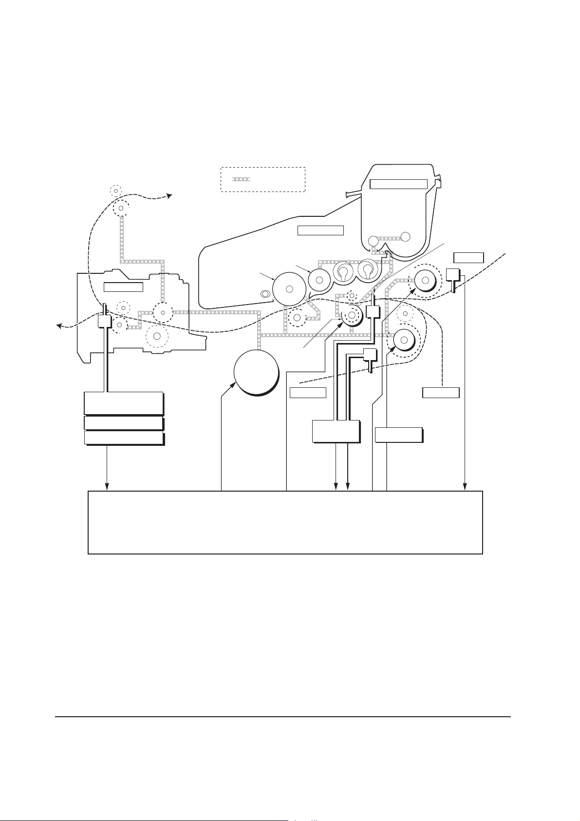
4-2-1 Paper feed control
The following diagram shows interconnectivity of the feeding system components including the
sensors and rollers. The engine board provides the signals in conjunction with the electrophotography
process that is driven by the main board.
8
Fuser unit
Exit
sensor
Power supply board
High voltage board
7
Bias board
6
Drum
Main
motor
Power train
Developing
roller
Registration
clutch
Process unit
5
Cassette
Bias board
3
Toner container
4
Paper
sensor
Main motor
TK-17
2
1
MP feed
clutch
Feed
clutch
Cassette
Optional
paper feeder
PF-17
Registration
sensor
MP tray
MP paper
sensor
FS-1050
EXITN
YC11-8
1 MP feed roller 3 Lower registration roller
5 Transfer roller 6 Heat roller 7 Lower exit roller 8 Upper exit roller
MOTORN
YC04-8
2 Feed roller
RESDRN
YC03-2
Engine board
RESIT
PAP ERN
YC12-7
YC12-9
Figure 4-2-2 Paper feed control
4-16
MPFDRN
FEDDRN
YC04-1
YC09-2
4 Upper registration roller
HANDSN
YC07-2
Page 76
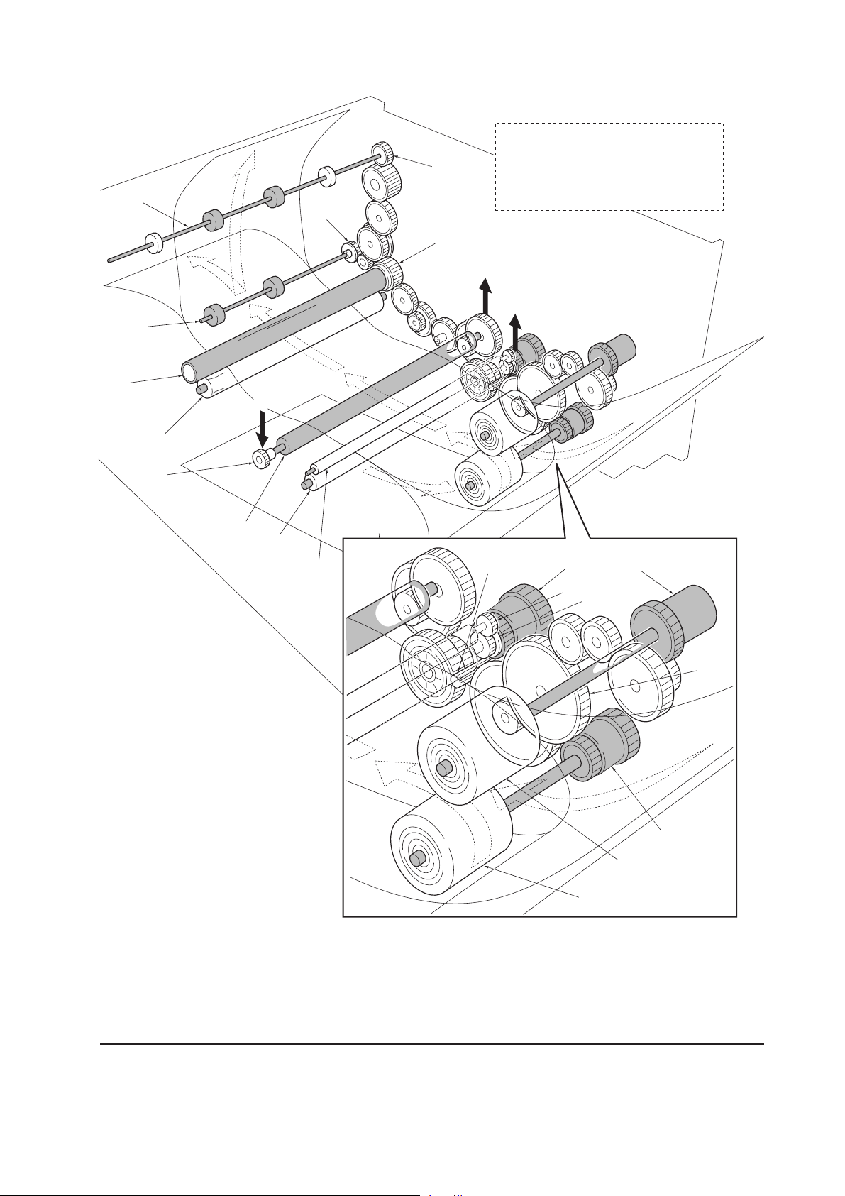
Paper feeding mechanism
(
&
%
C
$
#
*
)
^
Driving power train
A For process unit; drum (From main unit)
B For process unit; toner container,
developing roller etc. (From main unit)
C From process unit; drum
(To transfer roller)
A
B
@
0
1 Main motor (gear)
2 Registration clutch
3 MP feed clutch
4 Feed clutch
5 MP feed roller
6 Feed roller
7 Registration gear Z13
8 Registration gear Z20
9 Cassette gear
0 Lower registration roller
! Upper registration roller
@ Transfer roller
!
1
2
7
3
8
9
4
5
6
# TC gear Z18
$ Press roller
% Heat roller
^ Heat gear Z33
& Lower exit roller
( Upper exit roller
) Exit gear Z23 UP
* Exit gear Z23
Figure 4-2-3 Paper feeding mechanism
4-17
FS-1050
Page 77
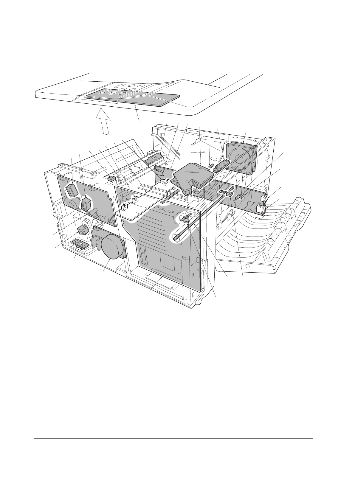
4-3 Electrical control system
4-3-1 Electrical parts layout
#
4
E
6
F
G
@
9
!
D
5
^
%
$
8
3
B
A
C
2
0
)
7
1
Main board (KP-888)
2 Engine board (KP-882)
3 Power supply board
A Power switch
B Exit sensor
C Inlet
4
LCD controller board
5 High voltage board
(KP-886)
1
6 Bias board (KP-884)
E Cassette switch
F Registration sensor
G Paper sensor
7 Main motor
8 Cooling fan
9 Registration clutch
0 Feed clutch
&
(
*
@ MP paper sensor
# Toner sensor
$ Waste toner sensor
% Eraser lamp
^ Laser scanner unit
& Heater lamp
* Thermal cutout
( Thermistor
D Interlock switch
FS-1050
! MP feed clutch
Figure 4-3-1 Electrical parts layout
4-18
)
Paper feeder interface connector
Page 78
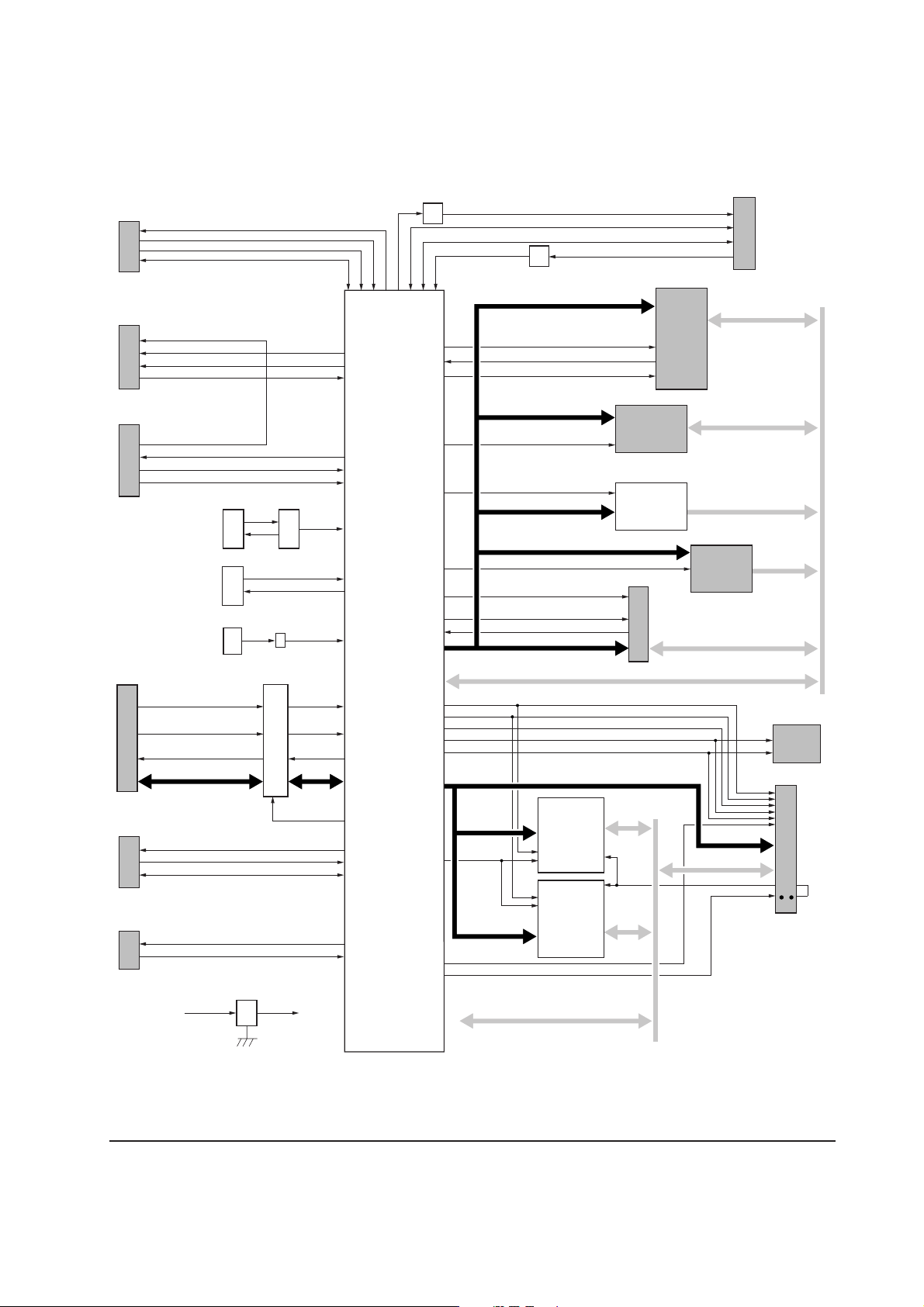
4-3-2 Operation of circuit boards
(1) Main board
Operator panel I/F
YC08
FPRSTN
FPCLK
FPDIR
FPDAT
YC07
APC I/F
LONB
VDFONSPL
PDN
YC06
Engine I/F
SCKN, SO, PLGCLK
SBSY, SI, SDIR, EGIRN, PDMASKN
RSTN
X’tal (System)
25.0000 MHz
X’tal (Video)
26.701882 MHz
X’tal (USB)
48.0000 MHz
YC04
Parallel I/F
PNSELIN
PNSTROBE, PNAUTOFD,
PNNIT
PNACK, PBUSY, PPERROR
PSELECT, PFAULT
PPDATA7-0
OUTPEN
X02 U13
X03
VXIN
VXOUT
X01
U11
CXIN
48MHZIN
NSELIN
PDATA7-0
Q01
Digital Transistor
CPU
U01
PowerPC 200 MHz
RISC processor
(Core ASIC)
Q02
Digital Transistor
EBA22, EBA10-1
EBCSN2, EBCSN3
EBOEN1, EBWEN1
CDWAITN, CDET1-2
CDRST
EBA22-2
EBCSN0, EBCSN1
EBOEN0, EBWEN0
EBCSN0, EBOEN2
EBA21-1
EBCSN1, EBOEN2
OPRSTN
OPRDY, DMAACKN, IORN,
IOWN, EBCSN4
DMAREQ, OPACKN, OPIRN
EBA15-1
EBIU Address bus
DQMUU, DQMUM
IICSCL
IICSDA
SDCSN0
RASN, CASN, WEN, BA1, BA0, SDCLKE
USBINT
USBDP
USBDN
VBUL
EBA21-1
EBIU Data bus
DQMLM, DQMLL
SDRAM Address bus
Memory
YS01
System DIMM
Slot 1
(Code ROM)
U02
Font
Mask ROM
YC01
Option I/F
KUIO-LV (3.3 V)
SDA12-0
YC02
Option
card
slot
EBD31-16
U03
API ROM
Socket
EBD31-16
EBD31-0
YC03
EDB31-16
USB I/F
EBD31-16
U07
EEPROM
YS02
IIC
Option serial I/F
YC05
DTR, RTS, TXD
CTS, DSR, RXD
RSSEL
[Debugger connector]
YC09
DBTXD
DBRXD, DBCLK
3.3 V Regulator
+5 V1
P1284DIR
U9
+3.3 V1
SDA12-0
SDCSN0
SDA12-0
SDRAM Data bus SDD31-0
U04
SDRAM
U05
SDRAM
SDCSN1-2
Figure 4-3-2 Main board circuit block diagram
4-19
SDD15-0
SDD31-16
SDCLK
SDA12-0
SDD31-0
SDCLK
Option
SDRAM
DIMM
Slot
FS-1050
Page 79
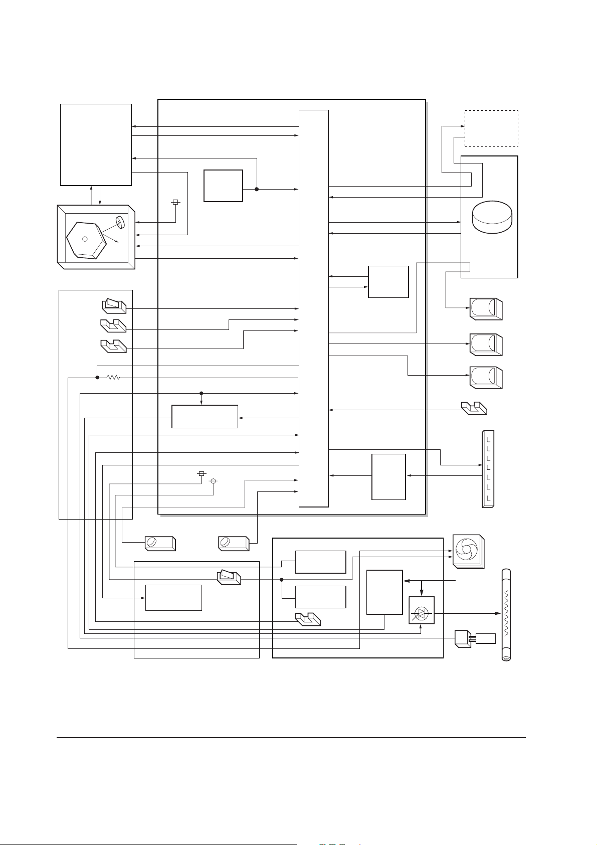
(2) Engine board
Main board
(KP-888)
RSTIN
PLGCLK
Reset IC
U02
Engine board (KP-882)
RSTN
Optional
paper feeder
PFMDRN
PFSEN, PFPFPER, PFCLK
Laser scanner unit
Cassette
switch
Regist-
ration
sensor
Paper
sensor
Bias board
(KP-884)
PLGDRN
PLGRDYN
SWIN
RESIT
PAPERN
FANH
FANL
THERMA
Heater lamp
control circuit
MHVDR, THVDR, RTHDR, HVISEL, HVCLK
24 V DC
5 V DC
HEATN
ZCROSS
EXITN
TONER
TNFULL
CPU
U01
MRDYN
EEDIO
EESCK
HANDSN
ERASPW
ERASER
MOTORN
EEPROM
U03
FEDDRN
RESDRN
MPFDRN
Eraser
lamp
control
circuit
Main motor
Feed clutch
Registration clutch
MP feed clutch
MP paper sensor
Eraser
lamp
FS-1050
Waste
toner
Toner sensor
High voltage
output circuit
sensor
Interlock
switch
High voltage board
5 V DC
output circuit
24 V DC
output circuit
Exit
sensor
Power supply board
Zero
cross
signal
detection
circuit
Figure 4-3-3 Engine board circuit block diagram
4-20
Cooling fan
Heater
lamp
AC input
Tr i ac
Thermistor
Page 80

Eraser lamp control circuit
The CPU (U01) turns pin #23 (ERASERN) of U01 to H level, transistors (Q16 and Q14) turns on
consequently, and the 24 V DC given at pin #1 of connector YC05 applies to the eraser lamps. The
eraser lamps thus illuminate as the current flows through the eraser lamp, the pin #2 of connector
YC05, resistors (R75/R76, and R77/R78), and the ground.
Pin #27 (ERRDYN) of the CPU (U01) is wired to the crossing of resistors (R75/R26 and R77/R78)
via resistor (R74). The U01 turns pin #23 (ERASERN) to H level and monitors the input level after
one second. If the eraser lamp is normal, the current flowing through R74 also flows the zener
diode (DZ01), making the voltage at pin #27 to be approximately 3.7 V. On the contrary, if the level
at pin #27 (ERRDYN) is less than 1 V for more than 2 seconds, despite the U01 turns pin #23
(ERASERN) to H level and applying the 24 V DC to pin #1 of connector YC05, the U01 recognizes
that the current is not flowing through the eraser lamp. The message “Call service 5300” is
then displayed.
Engine board
+24V
CPU
U01
P25/ASCK0
23
ERASERN
Eraser lamp cotrol circuit
2
Q16
3
1
GND
R69
R68
2
1
3
Q14
C33
YC05
1
2
3
Eraser lamp
ERASPW
ERASER
P16/ANI6
27
ERRDYN
1
2
GND
R74
DZ01
R75 R76
R77
GND
R78
Figure 4-3-4 Eraser lamp control circuit
PGND
4-21
FS-1050
Page 81

Heater lamp control circuit
Activation of the heater lamp is dominated by the HEAT signal which is derived by the engine CPU
(U01) at its pin #1. When its level is high, transistor QA03-a turns on, photo-triac PC2 and triac
TRC1 turn on simultaneously, and the heater lamp is applied with the primary AC voltage in turn.
Switching of triac TRC1, as affected by the HEAT signal is made in synchronization with the zero-
cross signal ZCROSS which is generated by the power supply unit. The zero-cross signal detector
watches the transition of alternating plus and negative current and detects the zero crosses. This
detector derives the resultant ZCROSS signal at its pin #43 of the engine CPU (U01). Since abrupt
change in the current flow can be significantly avoided by synchronizing triac TRC1 with the zero-
cross signal, the possibility of noise due to the primary AC supply is greatly reduced.
Engine board
Thermal cutout
Heat roller
Heater lamp
P10/ANI0
CPU
U01
P50/A8
P00/INTP0
33
THERMA
1
HEAT
43
ZCROSS
AC input
GND
+5V
R52
R56
GND
Power supply unit
Tr iac
(TRC1)
Heater lamp control circuit
U04-1
2
−
1
393
3
+
GND
Zero
cross
signal
detection
+24 V
circuit
(PC2)
Photo-triac
+5V
+5V
Q11
Bias
board
QA03-b
QA03-a
GND
High
voltage
board
FS-1050
Thermistor
Figure 4-3-5 heater lamp control circuit
4-22
Page 82

The AC power for the heater is applied in one of the five variations of the zero cross switchings as
shown in Figure 4-3-6. Each variation is constituted with the unit of ten positive and negative
envelops in five cycles, as obtained by varying the duration during which TRC1 turns on. The
heater lamp is energized while TRC1 is kept on; the heater lamp is turned off while TRC1 is kept
off. For example, the duty cycle (the period of a cycle during which the heater lamp is turned on) is
maximum for variation No.1 as the heater lamp is energized for the whole envelops. The duty cycle
is 60 % for variation No.3 as the heater lamp is energized for the 6 positive and negative envelops
out of 10. The duty cycle is 0 since the heater lamp is kept turned off for the whole envelops.
CPU (U01) selectively switches among those variations for applying voltages to the heater lamp
according to the THERMA signal which appears at pin #33 as feedback.
A fraction of THERMA is applied to pin #2 of comparator U04-1. The comparator maintains
comparison of the potential at pin #2 and pin #3 which gives a reference for the possible anomaly
in the heater temperature (bred by resistors R52 and R56). Should the voltage at pin #2 exceed that
at pin #3, the level at pin #1 becomes low. Since pin #1 is wired to the output line for the HEAT
signal, the HEAT signal is enforced to be low regardless the behavior of CPU (U01), thus preventing
possible heat overrun. The message “Call service 6110” is then displayed.
4-23
FS-1050
Page 83

Heater lamp turn-on pattern in 1 cycle (10 half waves)
Variation
No.1
(Duty 100 %)
Conductivity
staus of Triac
(TRC1)
Variation
No.2
(Duty 80 %)
Variation
No.3
(Duty 60 %)
AC wave
+
0 V
−
+
0 V
−
+
0 V
−
12345678910
Zero
cross
point
On On On On On On On On On On
On On On On On On On On Off Off
Variation
No.4
(Duty 40 %)
Variation
No.5
(Duty 0 %)
On On Off On On Off On On Off Off
+
0 V
−
On Off
+
0 V
−
Off Off Off Off Off Off Off Off Off Off
Off On Off Off On On Off Off
Figure 4-3-6 heater lamp turn-on variations
FS-1050
4-24
Page 84
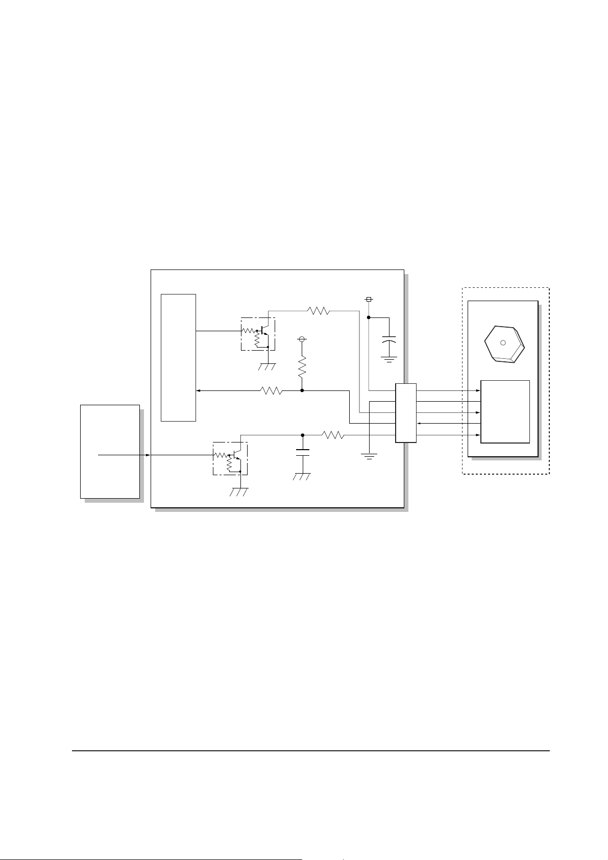
Polygon motor control circuit
The main controller board supplies the 1700.8 Hz clock pulse (PLGCLK) via the engine board to
the PLL control IC (IC1) for the polygon motor. To begin printing, the engine CPU U01 turns
PLGDR to H level, the PLL control IC (IC1) starts to revolve the polygon motor so that the revolution
is 17,008 rpm which depends on the PLGCLK clock pulse. When PLL control IC (IC1) finds that
the polygon motor is revolving at the rated speed, turns PLGDRN to L level to acknowledge the
engine CPU that the rated speed has been achieved.
On the contrary, if PLGRDYN does not turn to L level within 8 seconds since PLGDRN has been
L level, the printer displays “Call service 4000”.
Engine board
Laser scanner unit
Polygon motor
17,008 rpm
PLL
control IC
(IC1)
Main board
PLGCLK
CPU
U01
1700.8 Hz
Polygon motor control circuit
3
PLGDR
PLGRDYN
2
2
3
1
Q09
1
GND
R32
Q10
R35
+5V
GND
R38
C18
R41
+24V
PGND
PGND
5
4
3
2
1
YC06
+
+24V
PGND
PLGDRN
PLGRDYN
PLGCLK
Figure 4-3-7 Polygon motor control circuit
4-25
FS-1050
Page 85

(3) Power supply board
The power supply board provides the AC power input and DC power and outputs. The high voltage
bias generator circuit is mounted on a separate board. A simplified schematic diagram is shown
below.
Power supply unit
Powe r
AC
input
Current
switch
fuse
(SW1) (F1)
Noise
filter
circuit
FET
(Q1)
Switching/
Over
current
detection
circuit
Tr ansformer
(T1)
24 V DC
rectifier/
smoothing circuit
24 V DC
shutoff
circuit
5 V DC
rectifier/
smoothing circuit
Exit
sensor
EXITN
+24 V COM
SLEEP
FAN
Cooling fan
+24 V COM
+5 V
PGND, SGND
THERM
Heater
lamp
Thermal
cutout
Tr i ac
(TRC1)
Photo-
coupler
(PC1)
Photo-
coupler
(PC3)
PhotoTr i ac
(PC2)
Over voltage
detection
circuit
Tr ansistor
(Q8)
Zero cross signal
detection circuit
Figure 4-3-8 Power supply board circuit block diagram
Thermistor
+24 V
ZCROSS
HEAT
FS-1050
4-26
Page 86

(4) Bias board
The bias board contains the developing bias output circuit, registration sensor, paper empty sensor,
and the cassette switch. It also provides a liaison connection to the high voltage board, power
supply, and the toner sensor.
Bias board (KP-884)
Power supply
board
+5 V
+24 V
Toner
sensor
High voltage
board
TONER
5 V DC
24 V DC
FAN
+5 V
+5 V
+24 V
Registration
sensor
Paper
sensor
+24 V
+24 V
Casette
switch
Engine board
TONER
+5 V
5 V DC
24 V DC
SENPOW
RESIT
SWIN
PAPERN
RTHVDR, HVISEL
PSEL1, PSEL2
FANL
FANH
HEATN, ZCROSS
EXTIN, THERM
275 V DC + AC
Developing bias
output circuit
Developing
roller
HVCLK
Figure 4-3-9 Bias board circuit block diagram
4-27
FS-1050
Page 87

(5) High voltage board
The high voltage board contains the high voltage output circuit, interlock switch circuit as well as
providing a liaison connection with the power supply board, bias board, and the engine board.
High voltage board
High voltage output circuit
Engine board
Bias board
MHVDR
THVDR,
RTHVDR
PSEL1,
PSEL2
HVISEL
+24V2
+5V
Control
and
driver
circuit
Control
and
driver
circuit
Tr ansfer bias
output
positive voltage
circuit
Interlock switch
Tr ansfer
roller
Power supply board
+24V2
+24V1
FAN,
HEATN, SLEEP
ZCROSS,
THERM, EXITN
+5V
Main
charger
FS-1050
Figure 4-3-10 High voltage board circuit block diagram
4-28
Page 88

Interlock switch
The interlock switch is located on the high voltage board and opened and closed in conjunction
with the front cover or the top cover via the interlock lever. This switch connects and disconnects
the +24 V DC power supply line. If the front cover or the top cover is open, the interlock switch is
open, and the +24 V DC to the high voltage output circuit, bias board, engine board, and the power
supply board is disconnected, deactivating the high voltage output, laser output, main motor output
for safety. The cooling fan is an exception: Since the cooling fan is directly fed with +24 V DC from
the power supply unit at the primary side (+24V1) of the interlock switch, the cooling fan is not
deactivated even the cover is open.
Top cover
Projection
Interlock lever
Projection
Power supply unit
Tr iac, etc.
+24 V DC
output
Cooling fan
Engine board,
Bias board,
etc.
+24V2
+24V1
High voltage
output circuit
High voltage board
Interlock
switch
Figure 4-3-11 Interlock switch
Front cover
Machine left side view
4-29
FS-1050
Page 89

Chapter 5
Disassembly
Page 90

Chapter 5 Contents
5-1 General instructions ........................................................................................................................ 5-3
5-1-1 Screw/hardware ......................................................................................................................... 5-3
5-1-2 Before starting disassembly ...................................................................................................... 5-3
5-2 Disassembly ..................................................................................................................................... 5-4
5-2-1 Removing the process unit ........................................................................................................ 5-4
5-2-2 Removing the principal outer covers ......................................................................................... 5-5
(1) Removing the top cover/face-down output tray ................................................................... 5-5
(2) Removing the right cover .................................................................................................... 5-6
(3) Removing the left cover ....................................................................................................... 5-6
5-2-3 Removing the feed roller ........................................................................................................... 5-7
5-2-4 Removing the MP tray feed roller .............................................................................................. 5-8
5-2-5 Removing the transfer roller .................................................................................................... 5-10
5-2-6 Removing the principal circuit boards .......................................................................................5-11
(1) Removing the engine board ...............................................................................................5-11
(2) Removing the main board ................................................................................................. 5-12
(3) Removing the power supply board and high voltage board .............................................. 5-14
(4) Removing the bias board .................................................................................................. 5-15
5-2-7 Removing the main motor and drive unit ................................................................................. 5-16
5-2-8 Removing and splitting the fuser unit ...................................................................................... 5-20
(1) Removing the separators .................................................................................................. 5-22
(2) Removing the heater lamp ................................................................................................ 5-23
(3) Removing the heat roller ................................................................................................... 5-24
(4) Removing the thermistor ................................................................................................... 5-26
(5) Removing the thermal cutout ............................................................................................ 5-27
(6) Removing the press roller ................................................................................................. 5-28
5-2-9 Removing the laser scanner unit and the eraser lamp ............................................................ 5-29
5-2-10 Removing the main charger unit ............................................................................................ 5-32
Page 91

5-1 General instructions
This chapter provides procedures for removal and replacement of the field replacement components.
For other components not explained in this chapter, the diagrams in the Parts Catalog attached
with this manual will help locate the component.
When replacing of a component, reverse the procedure for the removal procedure explained in this
chapter.
WARNING To avoid injury to human bodies, make sure that AC power is removed and the
power cord is unplugged from both the power line and the printer.
5-1-1 Screw/hardware
Screws and hardware used in the printer are listed in the Ecosys Screw catalog. These screw symbol
numbers are universal to most Ecosys printers.
CAUTION When securing a self-tapping screws, align it with the thread carefully. First turn
it counterclockwise, then slowly clockwise. Do not overtighten. In case the self-
tapped thread is damaged, the affected part must be replaced with a new part.
5-1-2 Before starting disassembly
Before proceeding, unplug the power cord from the printer and the power supply.
WARNING Never attempt to operate the printer with a component removed.
CAUTION The printer use electrostatic sensitive parts inside (on circuit boards, Laser scanner
unit, etc.). Provide an antistatic (discharging) device, such as a wrist strap, that
can effectively discharge your body before touching the circuit boards, the laser
scanner unit, etc.
5-3
FS-1050
Page 92

5-2 Disassembly
Before proceeding, remove the paper cassette and the optional paper feeder, if installed.
5-2-1 Removing the process unit
1. Open the top cover 1.
2. Open the front cover 2.
3. Lift the process unit 3 together with the toner container out of the printer.
1
2
3
Figure 5-2-1 Removing the process unit
CAUTIONS After removing the process unit, seal it in the protective bag and place it on flat
surface. Do not place the process unit in a dusty area.
Do not give impact to the process unit.
Do not place floppy disks near the process unit.
FS-1050
5-4
Page 93

5-2-2 Removing the principal outer covers
(1) Removing the top cover/face-down output tray
1. Open the top cover 1.
2. Remove two screws 2.
3. Remove one connector 3.
4. Remove the top cover/face-down output tray 4.
2
1
4
3
Figure 5-2-2 Removing the top cover/face-down output tray
5-5
FS-1050
Page 94
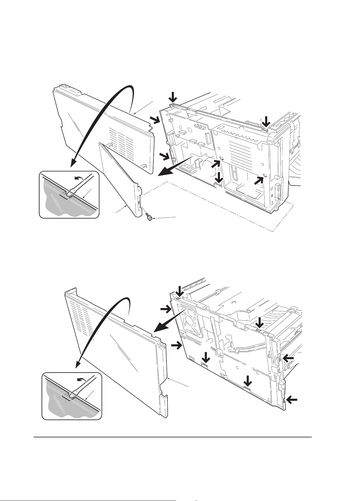
(2) Removing the right cover
1. Remove one screw 1.
2. Remove the side cover 2.
2. Unlatch the six snaps 3 and one hook hole 4 on the chassis, remove the right cover 5.
3
5
3
3
3
3
5
3
4
2
Figure 5-2-3 Removing the right cover
(3) Removing the left cover
1. Unlatch the six snaps 1 and two hook holes 2 on the chassis, remove the left cover 3.
1
1
FS-1050
3
1
1
1
2
1
2
3
1
Figure 5-2-4 Removing the left cover
5-6
Page 95

5-2-3 Removing the feed roller
CAUTION When refit the feed roller, fit the D-cut shaft into the D-shape hole of the feed
roller.
1. Remove the paper cassette and the process unit. (See page 5-4)
2. Stand the machine the front side up.
3. Move the feed roller in the direction A, and remove the feed roller 1.
A
1
Figure 5-2-5 Removing the feed roller
5-7
FS-1050
Page 96
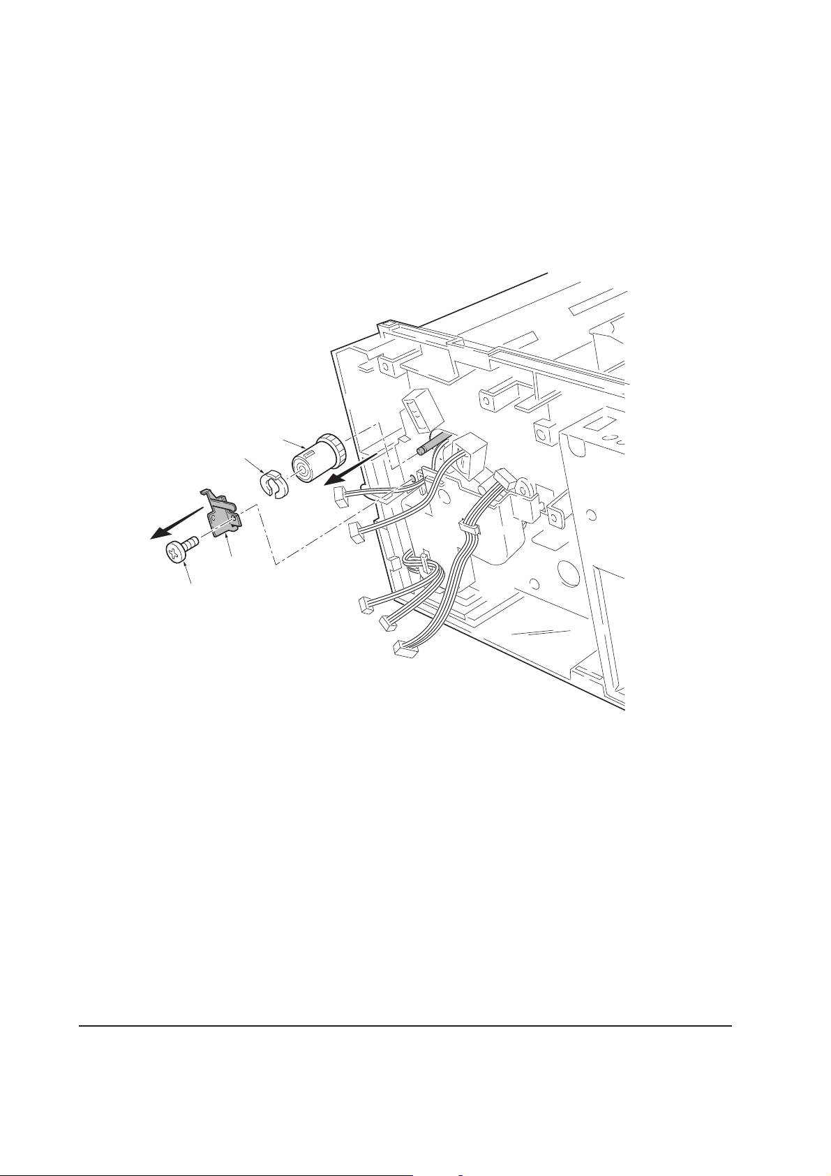
5-2-4 Removing the MP tray feed roller
1. Remove the engine board. (See page 5-11)
2. Remove one screw 1.
3. Remove the grounding plate 2.
4. Remove one stop ring 3.
5. Remove the MP feed clutch 4.
4
3
1
2
Figure 5-2-6 Removing the MP feed clutch
FS-1050
5-8
Page 97

6. Remove one screw 5.
7. Remove the toner sensor 6 and spring 7.
8. Remove two screws 8.
9. While pressing the latch 9 by using the driver and then remove the MP feed unit 0.
9
6
5
8
7
8
0
Figure 5-2-7 Removing the MP feed unit
10. Remove the stop ring ! and then remove the MP feed roller @.
@
!
Figure 5-2-8 Removing the MP feed roller
5-9
FS-1050
Page 98

5-2-5 Removing the transfer roller
CAUTION Do not touch the transfer roller (sponge) surface. Oil and dust (particles of paper,
etc.) on the transfer roller can significantly deteriorate the print quality (white
spots, etc.).
When refitting the bushes and springs, make sure to refit the black colored bush
and spring on the left side. Also, observe the correct direction to which the bush
is fit in reference to the paper passing direction.
1. Remove the process unit. (See page 5-4)
2. Remove the transfer roller 1 from the both bushes.
Paper passing direction
Gear
Bush
(Black colored)
Spring
(Black colored)
1
Long
Short
Tr ansfer roller
Bush
Bush
Spring
FS-1050
Figure 5-2-9 Removing the transfer roller
5-10
Page 99

5-2-6 Removing the principal circuit boards
(1) Removing the engine board
1. Remove the top cover/face-down output tray and right cover (See pages 5-5 and 5-6).
2. Remove all (ten) connectors from the engine board 1.
3. Remove three screws 2.
4. Remove the engine board 1.
2
1
Figure 5-2-10 Removing the engine board
5-11
FS-1050
Page 100

(2) Removing the main board
1. Remove the process unit (See page 5-4).
2. Remove the top/face-down output tray and right cover (See pages 5-4 and 5-5).
3. Remove two connectors 1 from main board 2.
4. Remove six screws 3.
5. Remove the controller box (with main board) 4.
1
3
3
FS-1050
1
4
2
Figure 5-2-11 Removing the controller box (with main board)
5-12
 Loading...