

Page 1

Fax System (F)
SERVICE
MANUAL
Published in Jul. ’02
843DB110
Page 2

Safety precautions
This booklet provides safety warnings and precautions for our service personnel to ensure the safety of
their customers, their machines as well as themselves during maintenance activities. Service personnel
are advised to read this booklet carefully to familiarize themselves with the warnings and precautions
described here before engaging in maintenance activities.
Page 3
Safety warnings and precautions
Various symbols are used to protect our service personnel and customers from physical danger and
to prevent damage to their property. These symbols are described below:
DANGER: High risk of serious bodily injury or death may result from insufficient attention to or incorrect
compliance with warning messages using this symbol.
WARNING:Serious bodily injury or death may result from insufficient attention to or incorrect compliance
with warning messages using this symbol.
CAUTION:Bodily injury or damage to property may result from insufficient attention to or incorrect
compliance with warning messages using this symbol.
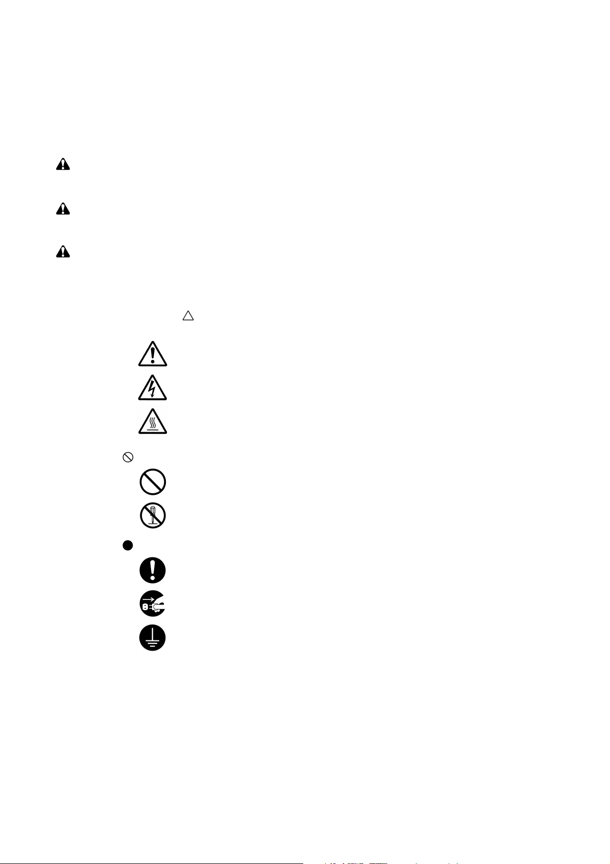
Symbols
The triangle ( ) symbol indicates a warning including danger and caution. The specific point
of attention is shown inside the symbol.
General warning.
Warning of risk of electric shock.
Warning of high temperature.
indicates a prohibited action. The specific prohibition is shown inside the symbol.
General prohibited action.
Disassembly prohibited.
indicates that action is required. The specific action required is shown inside the symbol.
General action required.
Remove the power plug from the wall outlet.
Always ground the copier.
Page 4

1. Installation Precautions
WARNING
• Do not use a power supply with a voltage other than that specified. Avoid multiple connections to
one outlet: they may cause fire or electric shock. When using an extension cable, always check
that it is adequate for the rated current. ............................................................................................
• Connect the ground wire to a suitable grounding point. Not grounding the copier may cause fire or
electric shock. Connecting the earth wire to an object not approved for the purpose may cause
explosion or electric shock. Never connect the ground cable to any of the following: gas pipes,
lightning rods, ground cables for telephone lines and water pipes or faucets not approved by the
proper authorities. .............................................................................................................................
CAUTION:
• Do not place the copier on an infirm or angled surface: the copier may tip over, causing injury. .....
• Do not install the copier in a humid or dusty place. This may cause fire or electric shock. ..............
• Do not install the copier near a radiator, heater, other heat source or near flammable material.
This may cause fire. ..........................................................................................................................
• Allow sufficient space around the copier to allow the ventilation grills to keep the machine as cool
as possible. Insufficient ventilation may cause heat buildup and poor copying performance. ..........
• Always handle the machine by the correct locations when moving it. ..............................................
• Always use anti-toppling and locking devices on copiers so equipped. Failure to do this may
cause the copier to move unexpectedly or topple, leading to injury..................................................
• Avoid inhaling toner or developer excessively. Protect the eyes. If toner or developer is
accidentally ingested, drink a lot of water to dilute it in the stomach and obtain medical attention
immediately. If it gets into the eyes, rinse immediately with copious amounts of water and obtain
medical attention. ..............................................................................................................................
• Advice customers that they must always follow the safety warnings and precautions in the copier’s
instruction handbook. ........................................................................................................................
Page 5

2. Precautions for Maintenance
WARNING
• Always remove the power plug from the wall outlet before starting machine disassembly...............
• Always follow the procedures for maintenance described in the service manual and other related
brochures. .........................................................................................................................................
• Under no circumstances attempt to bypass or disable safety features including safety
mechanisms and protective circuits. .................................................................................................
• Always use parts having the correct specifications...........................................................................
• Always use the thermostat or thermal fuse specified in the service manual or other related
brochure when replacing them. Using a piece of wire, for example, could lead to fire or other
serious accident. ...............................................................................................................................
• When the service manual or other serious brochure specifies a distance or gap for installation of a
part, always use the correct scale and measure carefully. ...............................................................
• Always check that the copier is correctly connected to an outlet with a ground connection. ............
• Check that the power cable covering is free of damage. Check that the power plug is dust-free. If
it is dirty, clean it to remove the risk of fire or electric shock. ............................................................
• Never attempt to disassemble the optical unit in machines using lasers. Leaking laser light may
damage eyesight. ..............................................................................................................................
• Handle the charger sections with care. They are charged to high potentials and may cause
electric shock if handled improperly. .................................................................................................
CAUTION
• Wear safe clothing. If wearing loose clothing or accessories such as ties, make sure they are
safely secured so they will not be caught in rotating sections...........................................................
• Use utmost caution when working on a powered machine. Keep away from chains and belts. .......
• Handle the fixing section with care to avoid burns as it can be extremely hot. .................................
• Check that the fixing unit thermistor, heat and press rollers are clean. Dirt on them can cause
abnormally high temperatures...........................................................................................................
• Do not remove the ozone filter, if any, from the copier except for routine replacement....................
Page 6
• Do not pull on the AC power cord or connector wires on high-voltage components when removing
them; always hold the plug itself. ......................................................................................................
• Do not route the power cable where it may be stood on or trapped. If necessary, protect it with a
cable cover or other appropriate item. ..............................................................................................
• Treat the ends of the wire carefully when installing a new charger wire to avoid electric leaks........
• Remove toner completely from electronic components. ...................................................................
• Run wire harnesses carefully so that wires will not be trapped or damaged. ...................................
• After maintenance, always check that all the parts, screws, connectors and wires that were
removed, have been refitted correctly. Special attention should be paid to any forgotten
connector, trapped wire and missing screws. ..................................................................................
• Check that all the caution labels that should be present on the machine according to the
instruction handbook are clean and not peeling. Replace with new ones if necessary. ...................
• Handle greases and solvents with care by following the instructions below: ....................................
· Use only a small amount of solvent at a time, being careful not to spill. Wipe spills off completely.
· Ventilate the room well while using grease or solvents.
· Allow applied solvents to evaporate completely before refitting the covers or turning the main
switch on.
· Always wash hands afterwards.
• Never dispose of toner or toner bottles in fire. Toner may cause sparks when exposed directly to
fire in a furnace, etc...........................................................................................................................
• Should smoke be seen coming from the copier, remove the power plug from the wall outlet
immediately. ......................................................................................................................................
3. Miscellaneous
WARNING
• Never attempt to heat the drum or expose it to any organic solvents such as alcohol, other than
the specified refiner; it may generate toxic gas. ................................................................................
Page 7

CONTENTS
1-1 Specifications
1-1-1 Specifications ........................................................................................................................................ 1-1-1
1-1-2 Parts names and their functions ............................................................................................................ 1-1-4
(1) Main body ...................................................................................................................................... 1-1-4
(2) Operation panel ............................................................................................................................. 1-1-5
(3) Basic fax screen on the touch panel .............................................................................................. 1-1-6
1-1-3 Mechanical construction ........................................................................................................................ 1-1-8
1-2 Installation
1-2-1 Unpacking and installation .................................................................................................................... 1-2-1
(1) Unpacking and installation ............................................................................................................. 1-2-1
1-2-2 Setting and registering data .................................................................................................................. 1-2-9
(1) Settings .......................................................................................................................................... 1-2-9
(2) Registration .................................................................................................................................. 1-2-10
1-2-3 Installing the optional memory module DIMM ..................................................................................... 1-2-11
1-3 Maintenance Mode
1-3-1 Maintenance mode ................................................................................................................................ 1-3-1
(1) Maintenance mode item list ........................................................................................................... 1-3-1
(2) Contents of maintenance mode items ........................................................................................... 1-3-4
1-4 Error Code
1-4-1 Error codes ............................................................................................................................................ 1-4-1
(1) Error code ...................................................................................................................................... 1-4-1
(2) Table of general classification ........................................................................................................ 1-4-2
(2-1) U004XX error code table: Interrupted phase B ..................................................................... 1-4-4
(2-2) U006XX error code table: Problems with the unit ................................................................. 1-4-5
(2-3) U008XX error code table: Page transmission error ............................................................... 1-4-5
(2-4) U009XX error code table: Page reception error .................................................................... 1-4-5
(2-5) U010XX error code table: G3 transmission ........................................................................... 1-4-6
(2-6) U011XX error code table: G3 reception ................................................................................ 1-4-8
(2-7) U017XX error code table: V.34 transmission ...................................................................... 1-4-10
(2-8) U018XX error code table: V.34 reception ............................................................................ 1-4-10
(2-9) U023XX error code table: Relay command abnormal reception ......................................... 1-4-10
(2-10) U044XX error code table: Encrypted transmission ............................................................. 1-4-10
3DB
1-5 Self Diagnosis
1-5-1 Self-diagnosis ........................................................................................................................................ 1-5-1
(1) Self diagnostic codes ..................................................................................................................... 1-5-1
1-5-2 Troubleshooting .................................................................................................................................... 1-5-3
1-6 Requirements on PCB Replacement
1-6-1 Updating the firmware ........................................................................................................................... 1-6-1
(1) Updating the firmware on the fax control PCB (Flash ROM) ......................................................... 1-6-1
(2) Updating the firmware on the fax control PCB (Compact Flash card) ........................................... 1-6-4
2-1 Electrical Parts Layout
2-1-1 Electrical parts layout ............................................................................................................................ 2-1-1
2-2 Operation of the PCBs
2-2-1 Fax control PCB .................................................................................................................................... 2-2-1
2-2-2 NCU PCB .............................................................................................................................................. 2-2-7
2-2-3 Auxiliary power source PCB ................................................................................................................ 2-2-11
1-1-1
Page 8

3DB
1-1-1 Specifications
Type .......................................................... Optional Fax Kit
Compatibility.............................................. Group 3
Line Requirement ...................................... Subscription telephone line
Transmission Speed .................................. Within 3 seconds (33600 bps, JBIG, ITU-T #1 chart)
Modem Speed ........................................... 33600/31200/28800/26400/24000/21600/19200/16800/14400/12000/9600/
7200/4800/2400 bps
Data Compression .................................... JBIG/MMR/MR/MH
Error Correction......................................... ECM
Maximum Document Dimensions ............. Width: 11" [297 mm] Length: 63" [1600 mm]
Automatic Document Feeder Capacity ..... Duplex document processor: Max. 100 pages, document processor: Max. 70
pages
Auxiliary Scanning Line Density ................ Horizontal × Vertical
Normal (8 dots/mm × 3.85 lines/mm)
Fine (8 dots/mm × 7.7 lines/mm)
Super fine (8 dots/mm × 15.4 lines/mm)
Ultra fine (16 dots/mm × 15.4 lines/mm)
Recording Resolution ................................ 600 dpi × 600 dpi
Grayscale .................................................. 128 levels (Value differential diffusion)
Speed-Dial Keys ....................................... Max. 600 destinations
Broadcast Transmission ............................ Max. 300 destinations
Polling Reception ...................................... Max. 300 locations
Installed Bitmap Memory .......................... 4 MB
Installed Imaging Memory ......................... 4 MB (including 1 MB of working memory)
Management Reports and Lists ................ Activity Report, Confirmation List, User Setting List, One-Touch Key List,
Telephone Directory List, Program Dial List, Group Dial List, Encryption Key
List, Restricted Access Report, Department List
Options ...................................................... Memory module DIMM (8 MB)
Functions................................................... See pages 1-1-2 to 1-1-3.
1-1-1
Page 9

3DB
Reception functions Manual reception
Automatic reception
Fax/telephone auto selection
TAD reception
D.R.D. reception*
1
Remote switching
Transmission functions One-touch dialing*
Program dialing*
Group dialing*
Chain dialing*
2
2
2
2
Redialing (manual/automatic)
Dial confirmation
Communication functions Direct feed transmission
Memory transmission
Direct reception
Memory reception (F-coded confidential reception and relay broadcast
reception)
Additional communication functions Broadcast transmission (up to 300 numbers)
Polling communication
Encrypted communication
Password check communication
Memory fax forwarding
Reserved transmission
Timer transmission
Interrupt transmission
Short protocol
ECM
F-coded transmission
F-coded confidential reception
F-coded bulletin board communication
F-coded relay broadcast
Supplementary communication functions Printing out from F-coded confidential box
Manual transmission
Telephone directory
Transmission destination display
Tone transmission
3
Memory back-up (60 min.*
)
Entry into F-coded bulletin board
Communication result display
Supplementary transmission functions Batch transmission
TTI transmission
Bulletin board
Rotation transmission
Duplex transmission*
4
Initial communication speed setting
Supplementary reception functions Memory reception
2-in-1 reception
Auto reduce reception
Rotation reception
Duplex reception*
5
Recording paper setting (auto selection, fixed size or fixed cassette)
During-reception copying
Reception date and time recording
1-1-2
Page 10

Reports Activity report
Transmission report
Reception report
Power failure report
Delayed communication report
Confirmation report
User settings list
Encryption key list
Management report
Department list
One-touch key list
Telephone directory list
Program dial list
Group dial list
F-code confidential box list
F-code relay box list
Encryption box list
Network fax setting list
Others Memory editing
Remote diagnosis
Department control for faxes
Network fax functions
3DB
*6
*6
*1: For 120 V specifications only.
*2: To be registered under one-touch keys. Up to 600 one-touch keys can be used for one-touch dialing, program dialing,
group dialing and chain dialing.
*3: When the optional memory module DIMM is installed.
*4: Available only when the duplex document processor is installed.
*5: Available only when the duplex unit is installed.
*5: When the printer/scanner kit is installed.
1-1-3
Page 11

3DB
1-1-2 Parts names and their functions
(1) Main body
Figure 1-1-1
Figure 1-1-2
1 Operation panel ..................................... Use the operation panel to perform the procedures required for fax
communication.
2 Fax storage section ................................ Received documents are ejected and stored face-down in the fax storage
section. Up to 250 sheets can be stored in this section at one time.
3 Drawers .................................................. This fax machine comes standard with two drawers installed. Each drawer
2
can hold up to 500 sheets of plain paper (60 g/m
- 105 g/m2).
4 Multi-Bypass .......................................... Paper can be set in the Multi-Bypass as well. In order to use the Multi-
Bypass, it is necessary to select “ON” under “Turning Manual Paper Feed
ON/OFF”.
5 Telephone jack (T) .................................. Use this jack to connect a separately purchased telephone to the fax.
6 Line jack (L) ........................................... Use this jack to connect the fax to a telephone line using the modular cord.
7 Main switch ............................................ Turn this switch ON ( | ) in order to perform fax and copy operations. The
message display will light and operation will be possible.
• Document Processor
There are 2 optional document processors available for use with this machine: the document processors for feeding onesided documents, and the duplex document processor for using both sides of 2-sided documents.
* Both the document processor and duplex document processor can be used with the 25 copies per minute machine.
However, only the duplex document processor can be used with the 35/40 copies per minute machine.
8 Document table...................................... Set the documents to transmit on the table. Up to 100 sheets of up to 11" × 8
1
/2" [A4] size paper, or up to 70 sheets of 8 1/2" × 14" or 11" × 17" [A3 or
Folio] size paper, can be set at one time when installing the duplex document
1
processor. Up to 70 sheets of up to 11" × 8
sheets of 8
1
/2" × 14" or 11" × 17" [A3 or Folio] size paper, can be set at one
/2" [A4] size paper, or up to 50
time when installing the document processor.
9 Document insert guides ......................... Adjust these guides to match the width of the documents.
10 Document processor reversing cover..... Open this cover if a document jams.
11 Document eject cover ............................ Documents are ejected onto this cover after being scanned.
1
12 Eject guide ............................................. Open this guide when transmitting documents of a large size such as 8
/2"
×14" or 11" × 17" [A3 or Folio].
13 Document processor open/close lever ... Operate this lever when opening and closing the document processor.
14 Document set indicator .......................... This indicator indicates the status of the documents set in the document
processor. Documents are set properly when the indicator is lit green.
1-1-4
Page 12

(2) Operation panel
3DB
Figure 1-1-3
1 Touch panel......................... Indicates operation procedures as well as trouble with the machine. Keys related to
operational procedures which appear on the touch panel with their name displayed are
indicated in this handbook within double quotation marks. In addition, you will be
instructed to “touch” any keys which appear on the touch panel rather than “press” them.
(Ex.: Touch the “xxx” key.)
2 Keypad ................................ Use the keypad to enter fax numbers, etc.
* Even if your telephone service is for pulse dialing, press the star (*) key and any key
pressed on the keypad after that will transmit the related tone signal. (Inch version
only)
3 Start key .............................. Press this key when you want to initiate a fax communication.
4 Fax key/Fax indicator .......... Press this key when you want to switch between the Copy Operation and Fax Operation
modes. The Fax indicator is lit when the machine is in the Fax Operation mode.
5 Fax data indicator ............... This indicator blinks during a fax communication. When received documents or other
data are being stored in memory, this indicator will flash and then light continuously.
6 Reset key ............................ Press this key when you want to cancel an operation in progress and have the touch
panel return to the initial mode settings.
7 Stop/Clear key..................... Press this key when you want to delete registered fax numbers or names, as well as
when you want to stop an operation in progress.
8 Fax Priority key ................... Press this key when you want to give priority to printing out a received fax during a copy
operation.
9 Default key .......................... Press this key when you want to perform settings related to the various default modes for
the fax functions of this machine.
Interrupt key/indicator lamp ..
10
Press this key when you want to interrupt a fax reception in order to make copies. The
indicator lamp in the Interrupt key will light when the machine is in the Interrupt mode.
1-1-5
Page 13
3DB
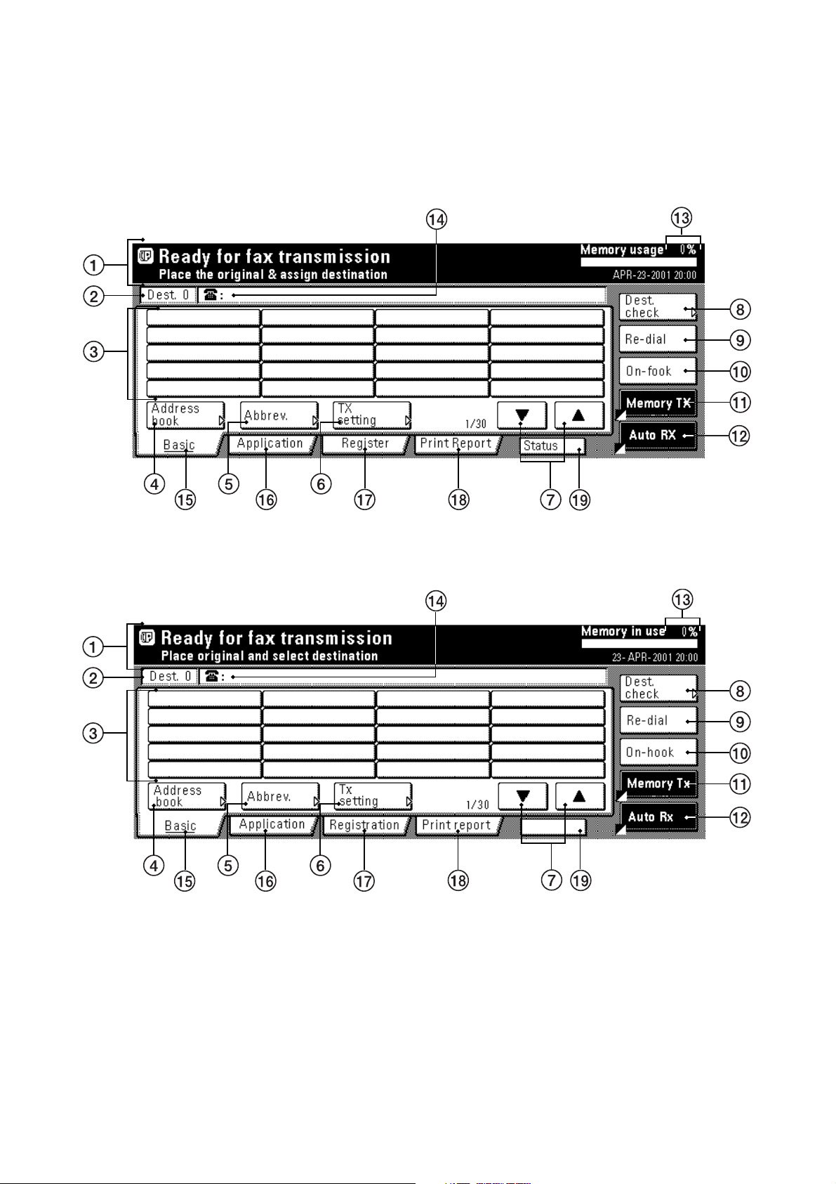
(3) Basic fax screen on the touch panel
The initial screen that appears in the touch panel when you press the Fax key in any other mode in order to change to the
Fax Operation mode is called the “basic fax screen”. The following contains information on the basic keys which are
displayed in this screen and their functions.
Inch
Metric
Act status
1-1-6
Figure 1-1-4
Page 14

3DB
1 Message display ........................... Current status, the next step in a procedure and error messages are shown in the
message display.
2 Number of destinations display ..... The number of destinations that you have chosen to dial to is shown in this area.
3 Speed-dial keys............................. Keys that you have registered to function as either a one-touch key, a group dial
key (G), a program key (P) or a chain dial key (C) are displayed here.
4 “Address book” key ....................... Touch this key when you want to use the address book.
5 “Abbrev.” key ................................. Touch this key when you want to use the abbreviated number that a destination
number is registered under in order to dial that number.
6 “TX setting” key ............................. Touch this key when you want to perform settings related to transmission
conditions such as the size of the documents to be transmitted, the image quality
of those documents, the contrast at which you want to send them and the time
when they should be sent. Once you press this key, the TX Setting screen will
appear.
” and “ ” cursor keys............... Use these keys when you want to display speed-dial keys other than those which
7 “
are currently displayed.
8 “Dest. check” key .......................... Touch this key when you have entered multiple destination fax numbers using
speed-dial keys, etc., and you want to check the list of those numbers.
9 “Re-dial” key .................................. Touch this key when you want to have the fax automatically redial the most
recently dialed number
10 “On-hook” key ............................... When a separately purchased telephone is connected to this fax machine and you
touch this key, you can dial a destination number without having to pick up the
receiver.
11 “Memory TX” / “Dir. Feed Tx” key .. When you want to switch between the Memory Transmission mode (“Memory Tx”)
and the Direct Feed Transmission mode (“Dir. Feed Tx”). The mode will change
each time you touch this key.
12 Reception mode select key ........... Touch this key when you want to select a different reception mode. The display will
change to the reception mode selection screen where you can select the desired
reception mode by touching the “Auto RX”, “Manual RX” or “Answering Machine”
key, as appropriate.
13 Memory bar ................................... Indicates the amount of data stored in memory. As documents are being stored,
the bar will move towards “100%” indicating that the data stored in memory is
increasing. Once it reaches “100%”, no more documents can be stored in memory.
14 Fax number display ....................... The number that you have entered to dial is displayed here.
15 “Basic” key .................................... Touch this key when you want to return to the basic fax screen.
16 “Application” key ........................... Touch this key when you want to use one of the various functions of this fax
machine such as polling, etc.
17 “Register” [“Registration”] key ....... Touch this key when you want to perform one of the various registration
procedures of this fax machine.
18 “Print Report” key .......................... Touch this key when you want to print out one of the various reports or lists of this
fax machine.
19 “Status” [“Act status”] key .............. This key is displayed during a transmission, reception or printout. Touch this key
when you want to verify the contents of the operation.
1-1-7
Page 15

3DB
1-1-3 Mechanical construction
PSPCB
CN8
1
LIVE(OUT)
MSW
LIVE
2
(IN)
TB3
MPCB
MSW REM
2
CN31
OPCB
24V
RELAY OUT
RELAY IN
1
NEUTRAL IN
TB2
TB1
APSPCB
TB3
1-1
1-5
1-4
5.2V
GND
RELAY REM
12V
1-3
1-2
GND
SP
BUBAT
SPEAKER
A.GND
BATT
G(5V)
YC8
6
5
3
1
7
8
9
YC7
1
2
YC6
1
2
YC4
DIMM (optional)
Memory Module
FCPCB
LINE
TEL
NCUPCB
YC3
YC1
CN44
Figure 1-1-5
The fax system consists of the fax control PCB (FCPCB), NCU PCB (NCUPCB), auxiliary power source PCB (APSPCB),
speaker (SP), backup battery (BUBAT) and optional memory module DIMM.
1-1-8
Page 16
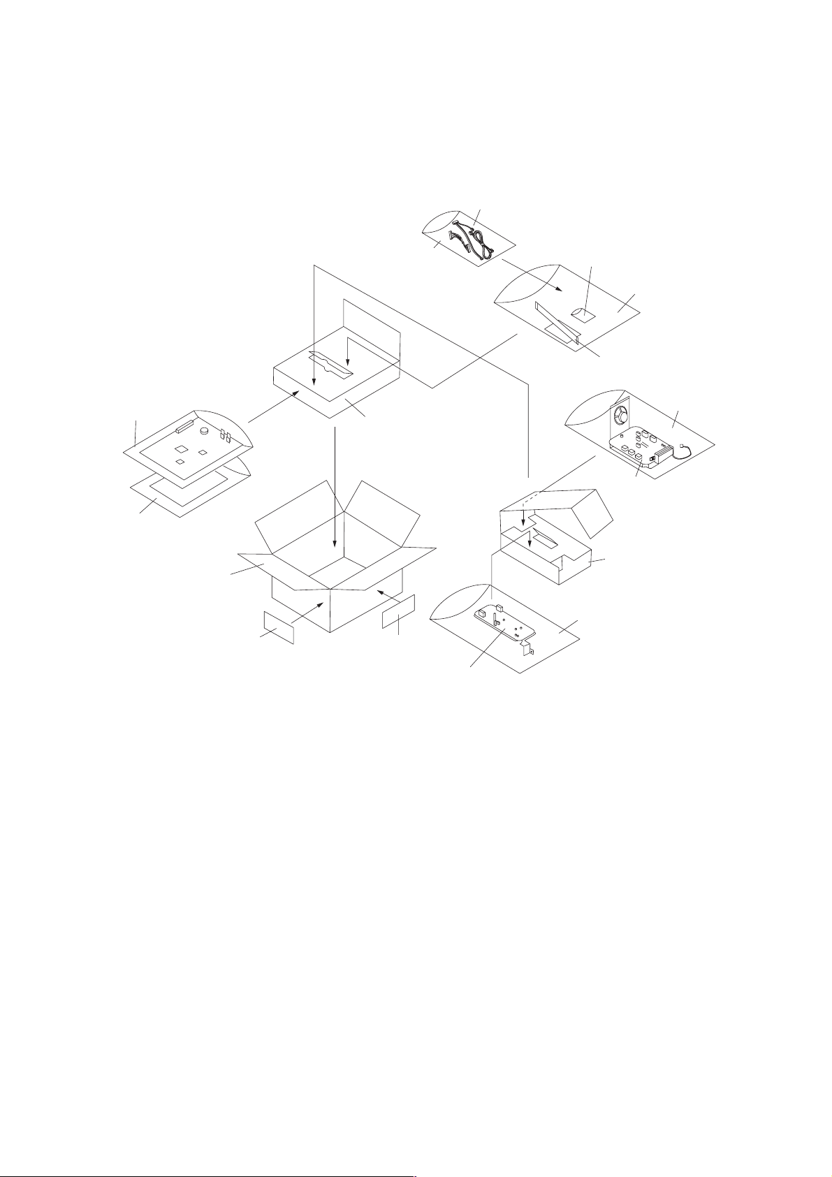
1-2-1 Unpacking and installation
(1) Unpacking and installation
3DB
790
12
*(
¤
‹
⁄
‹
!
%^
&
8@#$›
4
3
)
6
Figure 1-2-1 Unpacking
1 Fax control PCB
2 Antistatic air-padded bag
3 NCU board assembly
4 Antistatic air-padded bag
5 Auxiliary power source PCB
assembly
6 Antistatic air-padded bag
7 NCU cable
8 FCC68 label*
9 FAX-PCB-Power cable
0 “B” modular connector cable*
! Plastic bag
@ NW-FAX CD-ROM
# Fax cable
5
$ IC line label*
% TP-A chrome binding screw M3 ×
06
^ Plastic bag
& Plastic bag
* Operation guide
( Plastic bag
) Upper spacer
⁄ Bottom spacer
¤ Outer case
‹ Barcode labels
› Fax-kit label sheet
*For 120 V specifications only.
1-2-1
Page 17
3DB
Turn the machine’s main switch to OFF and unplug the copier from the power supply before starting this procedure.
<Procedure>
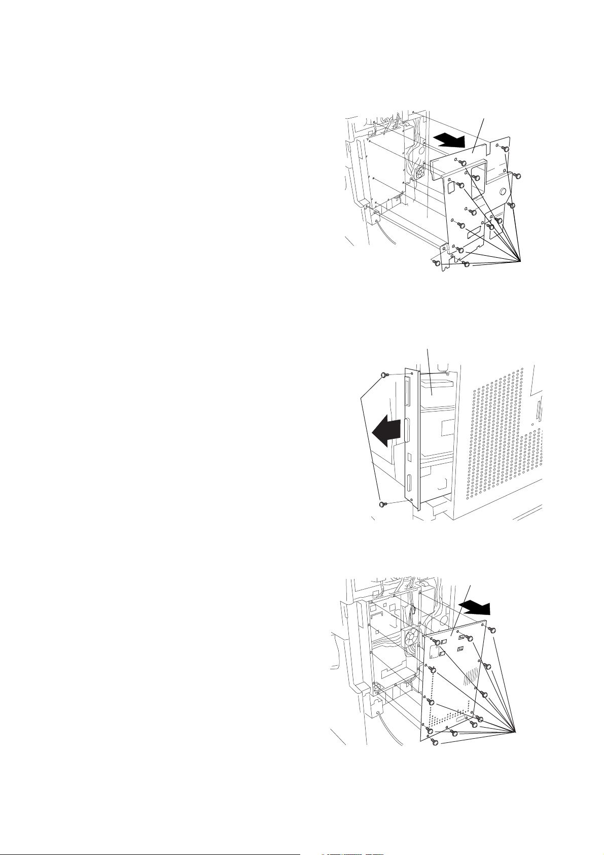
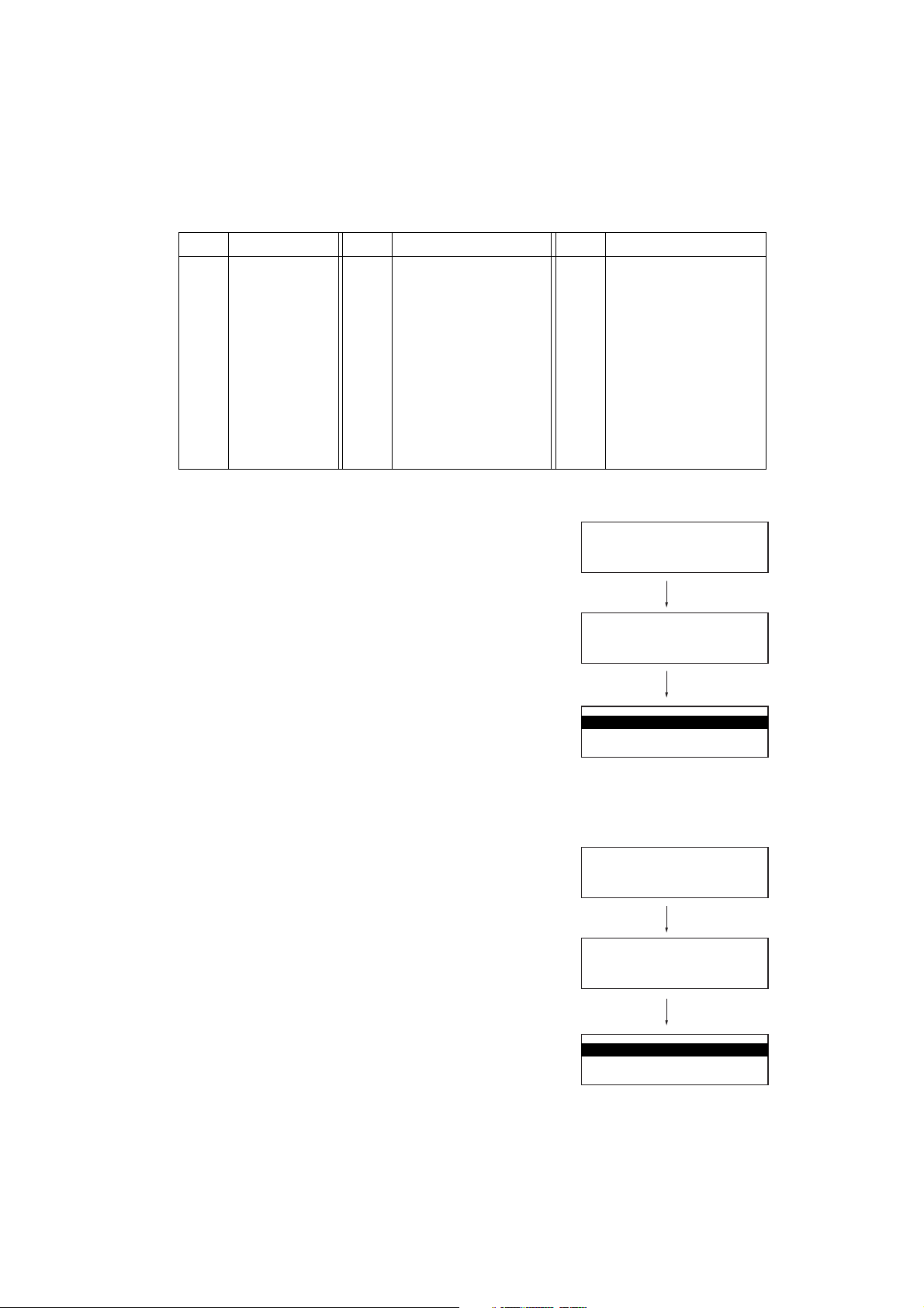
1. Remove 13 screws and take off the rear cover.
Rear cover
Screws
Figure 1-2-2
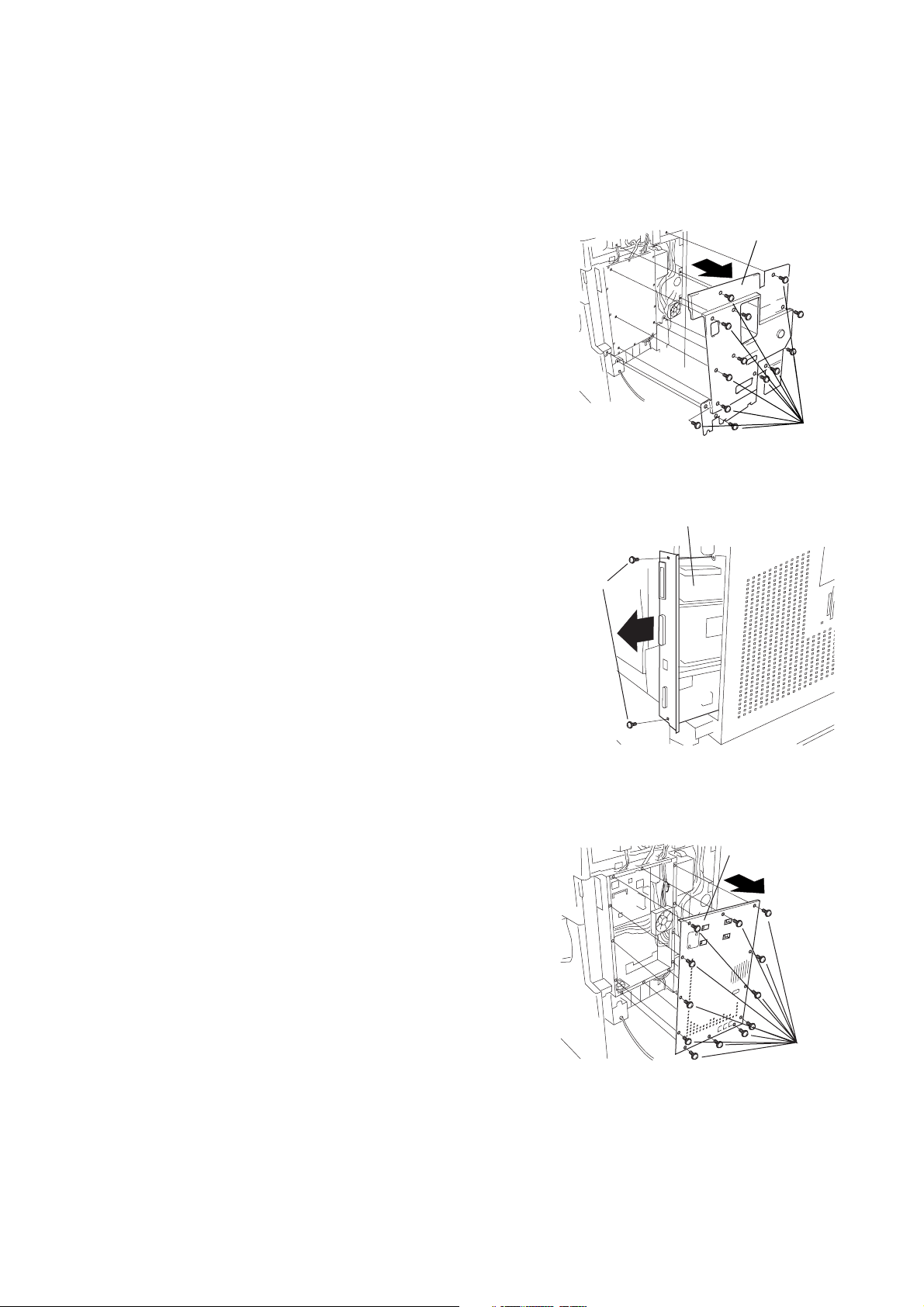
2. If the printing system is installed, remove the 2 screws and pull the
printing system out of the controller box.
3. Remove 13 screws and take off the controller-box cover.
Printing system
Screws
Figure 1-2-3
Controller-box cover
1-2-2
Screws
Figure 1-2-4
Page 18
3DB
g
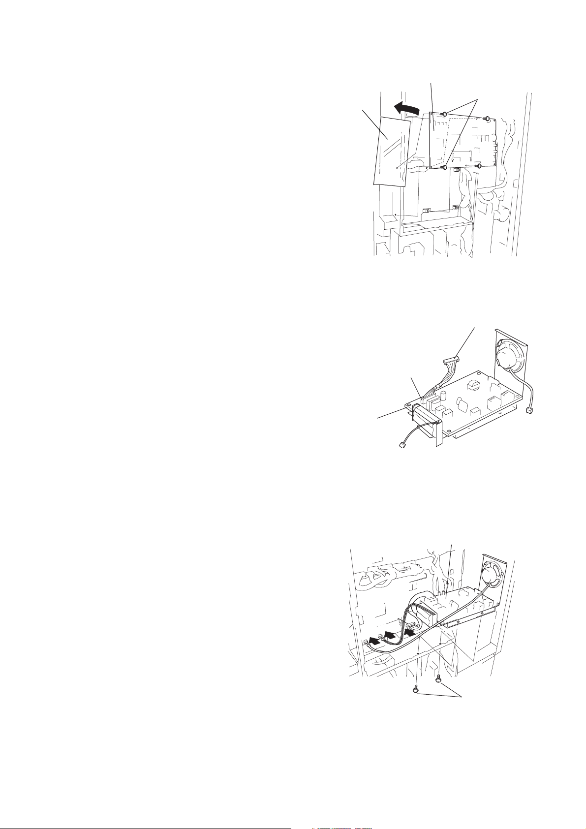
4. Move the shielding cover out of the way to the left, and fasten the
fax control PCB into place using four M3 × 06 chrome binding
screws.
5. Connect the NCU cable to connector CN1 on the NCU board
assembly.
Shielding cover
Fax control PCB
Figure 1-2-5
M3 × 06 chrome
binding screws
NCU cable
6. Fasten the NCU board assembly into place from the bottom with
two M3 × 06 chrome binding screws.
7. Connect the three connectors from the NCU board assembly to the
corresponding connectors on the fax control PCB, as follows:
• Speaker 2-pin connector → YC7
• NCU cable connector → YC3
• Battery connector → YC6
NCU board assembly
YC3
YC6
YC7
CN1
Figure 1-2-6
NCU board assembly
M3 × 06 chrome
screws
bindin
Figure 1-2-7
1-2-3
Page 19
3DB
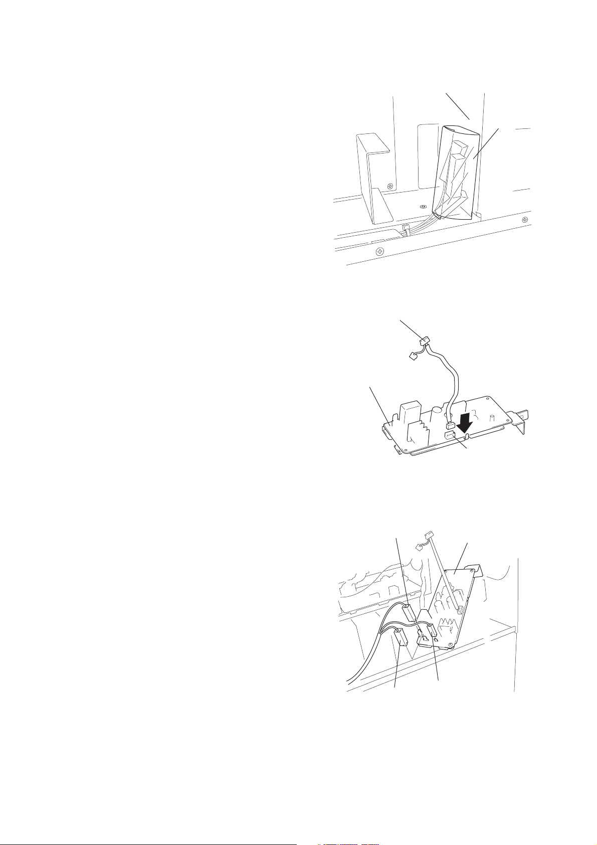
8. Remove the film that fixes the three positive connectors of the
power source PCB from the optional interface mounting plate.
Important: Dispose of the film that has been removed.
9. Connect the FAX-PCB-Power cable to connector CN1 on the
auxiliary power source PCB assembly.
Optional interface
mounting plate
Film
Figure 1-2-8
FAX-PCB-Power cable
10. Connect the three positive connectors on the power board to the
corresponding connectors on the auxiliary power source PCB
assembly as follows.
• White positive connector → TB1 (white)
• Green positive connector → TB2 (green)
• Small white positive connector → TB3
Auxiliary power source
PCB assembly
Green positive
connector
CN1
Figure 1-2-9
Auxiliary power source
PCB assembly
TB2
TB3
TB1
1-2-4
White positive
connector
Small white
positive connector
Figure 1-2-10
Page 20
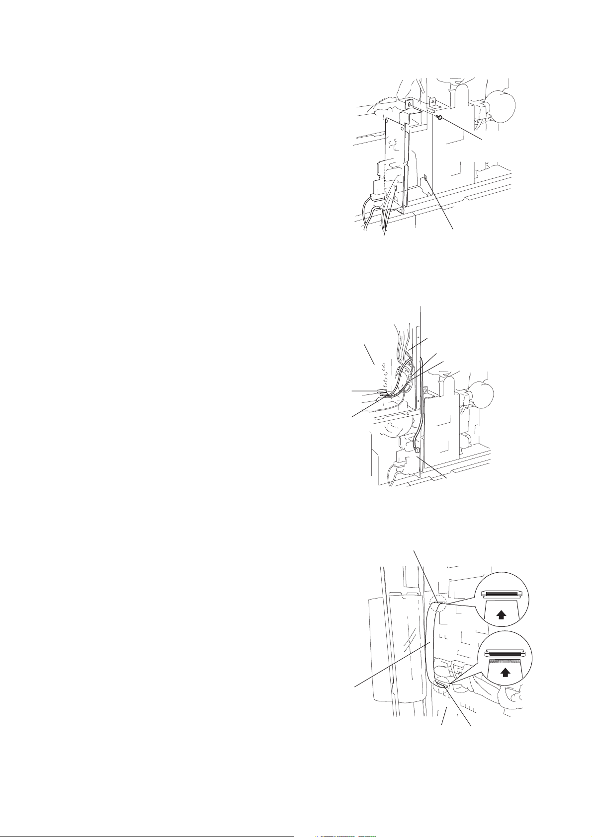
11. Fit the catch on the auxiliary power unit into the mount hole in the
y
copier, and fasten the auxiliary power unit into place with one M3 ×
06 chrome binding screw.
3DB
M3 × 06 chrome
binding screw
12. Through the opening of controller-box above the speaker, connect
the FAX-PCB-Power cable on the auxiliary power source PCB
assembly to connector YC8 on the fax control PCB.
13. Connect the 2-pin connector to the 2-pin connector with green
cable.
Fax control PCB
FAX-PCB-Power
YC8
cable
Catch
Mount hole
Figure 1-2-11
Opening
2-pin connector (green cable)
2-pin connector
Auxiliary power source
PCB assembl
Figure 1-2-12
14. Unlock YC1 on the fax control PCB by pulling its connector
housing.
15. Hold the fax cable with its conductive side facing up, insert it into
connector YC1, then push the housing back in to lock the
connector.
16. Hold the other end of the fax cable with its conductive side facing
down, and connect it to connector CN44 on the main PCB. (Pull
the CN44 housing out to release the connector lock, then insert the
cable, and then push the housing back in.)
Important: Be sure to push the fax cable all the way in, and be sure
that the connection is straight. A poor connection may result in a
variety of problems.
17. Refit the controller-box cover.
Fax cable
CN44
Fax control PCB
Figure 1-2-13
CN44
YC1
YC1
1-2-5
Page 21

3DB
18. Remove 1 screw and take off the modular cover.
19. Hang the modular cover onto the holes on the controller-box cover,
and fasten it into place with 1 screw.
20. If the printing system was installed, refit the printing system into the
controller box.
21. Refit the rear cover.
Screw
Modular cover
Figure 1-2-14
120 V specifications only
22. Adhere the IC line label and FCC68 label to the rear cover at the
locations indicated in the diagram.
Screw
Holes
Modular cover
Figure 1-2-15
IC line label
FCC68 label
1-2-6
Figure 1-2-16
Page 22

23. Take the power label from the fax-kit label sheet, and adhere it to
the copier directly under the main switch.
24. Take the alphabet labels from the fax-kit label sheet, and adhere
them above the corresponding numeric keys on the operation
panel.
• In Asia, use the “PQRS TUV WXYZ” label, and do not use the
“PRS TUV WXZ” and “OPER” labels.
Main switch
Alphabet labels
Figure 1-2-17
Management
ABC DEF
1
23
MNOJKL
4756
PQRS TUV
WXYZ
98
OPER
0
Reset
Interrupt
S
Start
Stop/
Clear
3DB
Power label
Energy Sever
25. Connect the telephone circuit to the L terminal by inserting the
modular connector cable into the line terminal (L).
Important: On 120 V specifications, use the included “B” modular
connector cable to make the connection.
Figure 1-2-18
Line terminal (L)
Modular connector
cable
Figure 1-2-19
1-2-7
Page 23
3DB
Initialization procedure after installation of facsimile system
1. Insert the machine power plug to the wall outlet and turn the main
switch on.
2. Run maintenance item U601.
3. Enter a destination code using the numeric keys (refer to the
destination code list) and then press the start key.
* Enter a destination code with three digits.
Code
000
009
080
084
088
108
126
136
137
152
156
4. Enter the OEM code (000) and then press the start key.
5. Confirm that the display is changed as shown in the illustration.
* At the position of @, the version number of the software is
displayed.
6. Press the cursor key to change the display to maintenance item
U602.
Destination
Japan
Australia
Hong Kong
Indonesia
Israel
Malaysia
New Zealand
Peru
Philippines
Middle East
Singapore
Code Code
159
169
181
242
243
253
Destination Destination
South Africa
Thailand
U.S.A.
South America
Saudi Arabia
CTR21 (European nations)
Italy
Germany
Spain
U.K.
Netherlands
253
Sweden
France
Austria
Switzerland
Belgium
Denmark
Finland
Portugal
Ireland
Norway
254
INI. KEEP DATA
COMPLETED XXX 000
INI. KEEP DATA
COMPLETED V@.@@
Taiwan
7. Press the start key and confirm that the display is changed as
shown in the illustration.
* At the position of @, the version number of the software is
displayed.
8. After completing the installation, run a communications test to
confirm that the fax system is working correctly.
SELECT THE MAINTENANCE NUMBER.
Initial keep data U601
Figure 1-2-20
INI. SHIP DATA
COMPLETED XXX 000
INI. SHIP DATA
COMPLETED V@.@@
SELECT THE MAINTENANCE NUMBER.
Initial ship data U602
Figure 1-2-21
1-2-8
Page 24

1-2-2 Setting and registering data
After setting up the machine, set or register the following data.
(1) Settings
3DB
• Setting the type of telephone line*
1
Select the setting (pulse or tone) according to the type of telephone line to be used.
• Setting the TTI transmission
Select whether or not to add the transmit terminal identifier (TTI) to the transmitting document.
• Setting report output condition
• Select the output condition for the management report (output or not output by department).
• Select the output condition for the activity report (output or not output after every 50 communications)
• Select the output condition for the transmission report (output or not output after each transmission)
• Select the output condition for the reception report (output or not output after each reception)
• Select the output condition for the timer communication report (output or not output after each timer programming).
• Select the output condition for the network fax transmission report.*
2
• Setting the password check communication
Select whether or not to perform password check communication.
• Setting the memory fax forwarding
Select whether or not to perform memory fax forwarding.
• Setting the bulletin board
Select whether or not to use the bulletin board during polling transmission.
• Setting the number of rings for automatic reception
Select the number of rings (1 to 15) that sound after call reception until fax data reception starts in the auto reception
mode.
• Setting the number of rings for TAD reception
Set the number of rings (1 to 15) that sound after call reception until fax data reception starts in the TAD reception
mode.
• Setting the number of rings for fax/telephone auto select mode*
1
Set the number of rings (0 to 15) that sound after call reception until fax data reception starts in the fax/telephone auto
select mode.
• Setting the speaker volume
Set the volume of the speaker in the on-hook mode (4 levels).
• Setting the alarm buzzer volume
Set the volume of the alarm that sounds during events such as when an error occurs (3 levels).
• Setting the monitoring volume
Set the volume for the sounds from the speaker (4 levels).
• Setting the document size for scanning from the document processor
Select the setting (“Standard size original” or “Long original”) for scanning the original fed from the document processor.
• Setting the default transmission mode
Select the transmission mode (memory transmission or direct feed transmission) to be used in the initial mode.
• Setting the reception mode
Select an automatic reception mode (automatic fax reception, fax/telephone auto selection or D.R.D. reception*
1
).
• Setting reception date and time recording
Select whether or not to record the date and time on received documents.
• Setting the paper feed selection mode
Select the paper feed mode (“Auto Selection mode”, “Fixed Size mode” or “Fixed Cassette mode”) for printing received
fax or reports.
• Setting the manual paper feed
Select whether or not to use the multi-bypass to feed paper for printing received faxes.
• Setting 2-in-1 reception
Select whether or not to output two successively-received A5/8
• Setting duplex reception*
Select whether or not to print received documents on both sides of the paper.
• Setting the network fax reception*
Set to perform network fax reception.
• Setting for saving the documents for transmission*
Select whether or not to save the transmitted documents on the server computer.
• Setting the file type*
3
2
2
2
1
/2" × 51/2" documents onto one A4R/81/2" × 11" page.
Select the file type in which the documents for transmission, or of received documents, will be saved in the server
computer.
• Setting remote diagnosis
Set to take advantage of our remote diagnosis system.
• Setting the restricted access
Turn the restricted access on or off.
*1: For 120 V specifications only.
*2: When the printer/scanner kit is installed.
*3: When the duplex unit is installed.
1-2-9
Page 25

3DB
(2) Registration
• Date and time
Set the current date and time.
• Self station information
Register the self telephone number, self station name and self station ID.
• One-touch dialing
Register destination fax (telephone) numbers and names under one-touch keys. Up to 600 entries can be registered.
• Group dialing
Register multiple destination fax (telephone) numbers and names under a one-touch key for group dialing. Up to 50
entries can be registered as group dial keys or program keys.
• Program dialing
Register frequently used communication modes or fax numbers under one-touch keys. Up to 50 entries can be
registered as program dial keys or group keys.
• Chain dialing
Register chain numbers and names under one-touch keys.
• F-code confidential boxes
Register F-code confidential boxes for F-code based confidential communication. Up to 100 boxes can be registered.
• F-code relay boxes
Register F-code relay box for F-code based relay broadcast communication. Up to 15 boxes can be registered.
• Encryption boxes
Register encryption boxes for receiving encrypted transmissions. Up to 15 boxes can be registered.
• Permit telephone numbers and IDs
Register the password (permit telephone number or ID) for password check communication.
• Fax forwarding
Register the destination and designated hours for fax forwarding.
• Remote switching number
Change the remote switching number, which is set to “55” at the factory, for receiving faxes using the telephone
connected to the machine.
• Remote test ID
Register the designated remote test ID for remote diagnosis.
• Management password
Register a 4-digit password, which is set to “6482” at the factory, for encrypted communication.
• Access codes
Register access codes for restricted access. Up to 50 codes can be registered.
• Cipher key password
Register a 16-digit cipher key password for encrypted communication.
• File name (transmission/reception)*
Register the default file name when documents which have been transmitted or received using the network fax
functions are saved in the designated folder.
• IP address / Host name*
Register the IP address or host name of the server computer in which documents which have been received using the
network fax functions are saved.
• Administrator’s e-mail address*
Register the e-mail address of the computer to be notified in case of an error, as well as where to send Transmission
and Reception Reports.
• Save folder number*
Register the number of the folder in which documents which have been transmitted or received using the network fax
functions will be saved.
*When the printer/scanner kit is installed.
1-2-10
Page 26
1-2-3 Installing the optional memory module DIMM
Memory module DIMM installation on the fax control PCB requires the following parts:
8 MB memory module DIMM (P/N: 2AW6001)
<Procedure>
1. Remove 13 screws and take off the rear cover.
3DB
Rear cover
Screws
Figure 1-2-22
2. If the printing system is installed, remove the 2 screws and pull the
printing system out of the controller box.
3. Remove 13 screws and take off the controller-box cover.
Printing system
Screws
Figure 1-2-23
Controller-box cover
Figure 1-2-24
Screws
1-2-11
Page 27

3DB
4. Insert the memory module DIMM (8MB) at an angle into the
memory slot on the fax control PCB.
Important: The memory module DIMM (8MB) must be installed
onto the fax control PCB. Please be sure that you do not install it
onto the main PCB.
5. Push the free end of the module down toward the fax control PCB.
6. Refit all removed parts.
Memory module DIMMMemory slot
Figure 1-2-25
1-2-12
Page 28

1-3-1 Maintenance mode
(1) Maintenance mode item list
Section
Fax
Item
No. setting*
U600 Initializing all data —
U601 Initializing permanent data —
U602 Setting factory defaults —
U603 Setting the user registration data
• Setting the self telephone number —
• Setting the type of telephone line —
• Setting the number of rings in the fax/telephone auto select mode —
• Setting remote diagnostic transmission —
U604 Clearing data
• Clearing transmission history —
• Initializing the management password —
• Initializing the F-code confidential box ID —
• Initializes the F-code relay box ID —
• Initializes the encription box ID —
U605 Setting the system (operational)
• Setting how to proceed if memory becomes full
during memory transmission —
• Setting an alarm for when reception is completed —
• Selecting if auto reduction in the auxiliary direction is to be performed —
• Setting the addition of an image to the report —
• Setting the error report display format —
• Setting the line-monitoring period —
• Setting the one-shot detection time for remote switching —
• Setting the continuous detection time for remote switching —
• Setting the initial condition of fax image scanning quality —
U606 Setting the system (operation unit and display)
• Setting the conditions under which an error indicator turns off —
• Setting the date format —
• Setting if the image scanning quality in fax mode is initialized —
• Setting if the scanning density in fax mode is initialized —
• Setting whether to skip unregistered abbreviated numbers
and one-touch key numbers on the list —
• Setting the used port entry in the activity report —
U607 Setting the system (communication 1)
• Setting the auto redialing interval —
• Setting the number of times of auto redialing —
• Setting the communication starting speed —
• Setting the reception speed —
• Setting the mode for remote switching —
• Setting the transmission intervals —
• Sets the loop current detection before dialing —
• Sets the DIS signal to 4 bytes —
U608 Setting transmission
• Setting the method to process errors —
• Setting the number of times of DIS signal reception —
• Setting the reference for RTN signal output —
• Setting the waiting period to prevent echo problem at the sender —
• Setting the waiting period to prevent echo problem at the receiver —
• Setting ECM transmission —
• Setting ECM reception —
• Setting the criteria for receiving a TCF signal 1 —
• Setting the frequency of the CED signal —
U609 Setting communication time
• Setting the T0 time-out time —
• Setting the T1 time-out time —
• Setting the T2 time-out time 69
• Setting the Ta time-out time 30
• Setting the Tb1 time-out time 20
• Setting the Tb2 time-out time 80
• Setting the Tc time-out time 60
• Setting the Td time-out time —
Maintenance item contents
3DB
Initial
1-3-1
Page 29

3DB
Section
Fax U610 Setting the modem output level
Item
No. setting
• Setting the modem output level —
• Adjusting the modem output level —
U611 G3 cable equalizer
• Setting the G3 transmission cable equalizer —
• Setting the G3 reception cable equalizer —
U612 Setting the modem detection level —
U613 Setting the DTMF output level
• Setting the DTMF (high-frequency group) output level —
• Setting the DTMF (low-frequency group) output level —
U614 Adjusting the DTMF output level
• Adjusting the DTMF (high-frequency group) output level —
• Adjusting the DTMF (low-frequency group) output level —
U615 Setting the NCU
• Setting the connection to PBX/PSTN —
• Setting PSTN dial tone detection —
• Setting busy tone detection —
• Setting for a PBX —
U616 Adjusting the ratio of make-to-break of dial pulses
• Make time (10 PPS) —
• Make time (20 PPS) —
U617 Outputting lists
• Settings list —
• Action list —
• Own-status report —
• Protocol list —
• One-touch dialing ECM setting list —
U650 Setting the system 1
• Setting the number of lines to be ignored when receiving a fax
at 100% magnification 3
• Setting the number of lines to be ignored when receiving a fax
in the auto reduction mode 3
• Setting the number of lines to be ignored when receiving a fax (A4R, letter)
in the auto reduction mode 3
• Setting the recording width for inch specifications —
• Setting automatic printing of the protocol list —
U651 Setting the system 2
• Setting the variation range in the auxiliary scanning direction
for rotation reception 3
• Setting the number of adjustment lines for automatic reduction 7
• Setting the number of adjustment lines for automatic reduction
when A4 paper is set 22
• Setting the number of adjustment lines for automatic reduction
when letter size paper is set 26
U660 Setting the system (communication 2)
• Setting the criteria for receiving a TCF signal 2 —
• Setting the short protocol transmission —
• Setting the reception of a short protocol transmission —
• Setting the CNG detection times in the fax/ telephone auto select mode —
• Turning ECM for one-touch dialing on/off —
U670 Setting the system (communication 3)
• Setting if V.34 transmission is available —
• Setting the V.34 symbol speed (3429 Hz) —
• Setting the V.34 symbol speed (3200 Hz) —
• Setting the V.34 symbol speed (3000 Hz) —
• Setting the V.34 symbol speed (2800 Hz) —
U680 Displaying the fax board ROM version —
Maintenance item contents
Initial
1-3-2
Page 30

3DB
Section
Fax
Others
Item
No. setting
U881 Using the flash-memory jig
• Saving data from SRAM into the jig —
• Writing data from the jig into RAM —
• Writing the boot program into the jig —
• Reading one-touch/abbreviated dial information —
• Writing one-touch/abbreviated dial information —
U882 Setting the software switches —
U894 Performing board test
• Performing tests on SRAM and DRAM —
• Performing tests on optional memory —
U898 Setting the ports for maintenance mode —
U992 Checking or clearing the printer/fax count —
Maintenance item contents
Initial
1-3-3
Page 31

3DB
(2) Contents of maintenance mode items
Maintenance
item No.
U600 Initializing all data
Description
Initializes software switches and all data in the SRAM on the fax control PCB, according to the destination and
OEM.
Purpose
Used to initialize the fax control PCB.
Method
1. Press the start key. The screen for entering the destination code is displayed.
Enter a destination code using the numeric keys (refer to the destination code list on page 1-3-5 for the
destination code).
INI. ALL DATA
COUNTRY CODE:000
2. Press the start key. The screen for entering the OEM code is displayed.
There is no operation necessary on this screen.
INI. ALL DATA
OEM CODE:000
3. Press the start key. Data initialization starts. To cancel data initialization, press the stop/clear key.
4. After data initialization, the entered destination and OEM codes are displayed, and the ROM version is
displayed two seconds later.
Description
INI. ALL DATA
COMPLETED 000 000
INI. ALL DATA
COMPLETED V1.00
Caution
If initialized with “000” (code for Japan) entered as the destination code, service call code C0820 (fax control
PCB problem) will be detected. Be sure to enter the correct destination code. If C0820 (fax control PCB
problem) is detected, press the COPY key to put the machine in the copy mode, open the front cover and then
execute this maintenance item again to enter the correct destination code and initialize data.
1-3-4
Page 32

3DB
Maintenance
item No.
U600
(cont.)
U601 Initializing permanent data
Destination code list
Code
000
009
080
084
088
108
126
136
137
152
156
Description
Initializes software switches other than that for machine data on the fax control PCB according to the
destination and OEM.
Purpose
Used to initialize the fax control PCB without changing user registration data and factory settings.
Method
1. Press the start key. The screen for entering the destination code is displayed.
Enter a destination code using the numeric keys (refer to the destination code list on page 1-3-5 for the
destination code).
Destination
Japan
Australia
Hong Kong
Indonesia
Israel
Malaysia
New Zealand
Peru
Philippines
Middle East
Singapore
Code
159
169
181
242
243
253
Description
Destination
South Africa
Thailand
U.S.A.
South America
Saudi Arabia
CTR21 (European nations)
Italy
Germany
Spain
U.K.
Netherlands
Code
253
254
Destination
Sweden
France
Austria
Switzerland
Belgium
Denmark
Finland
Portugal
Ireland
Norway
Taiwan
INI. KEEP DATA
COUNTRY CODE:000
2. Press the start key. The screen for entering the OEM code is displayed.
There is no operation necessary on this screen.
INI. KEEP DATA
OEM CODE:000
3. Press the start key. Data initialization starts. To cancel data initialization, press the stop/clear key.
4. After data initialization, the entered destination and OEM codes are displayed, and the ROM version is
displayed two seconds later.
INI. KEEP DATA
COMPLETED 000 000
INI. KEEP DATA
COMPLETED V1.00
Caution
If initialized with “000” (code for Japan) entered as the destination code, service call code C0820 (fax control
PCB problem) will be detected. Be sure to enter the correct destination code. If C0820 (fax control PCB
problem) is detected, press the COPY key to put the machine in the copy mode, open the front cover and then
execute this maintenance item again to enter the correct destination code and initialize data.
1-3-5
Page 33

3DB
Maintenance
item No.
U602 Setting factory defaults
Description
Initializes software switches other than that for machine data and the SRAM on the fax control PCB, according
to the destination and OEM.
Purpose
Used to initialize the fax control PCB to the factory default.
Method
1. Press the start key. Data initialization starts. To cancel data initialization, press the stop/clear key.
2. After data initialization, the entered destination and OEM codes are displayed, and the ROM version is
displayed two seconds later.
INI. SHIP DATA
COMPLETED 000 000
INI. SHIP DATA
COMPLETED V1.00
Description
1-3-6
Page 34

3DB
Maintenance
item No.
U603 Setting the user registration data
Description
Makes user settings to enable the use of the copier as a fax.
Purpose
To be run after installation of the facsimile kit if necessary.
Start
1. Press the start key. The screen for selecting an item is displayed.
2. Press the appropriate item.
The screen for the selected item appears.
Display
SELF TEL No.
LINE TYPE
RINGS (F/T) #
REMOTE DIAG
Setting the self telephone number
1. Enter the telephone number using the numeric keys.
Up to 20 digits can be entered.
To correct the entered telephone number or to delete the stored telephone number, reset by pressing the
stop/clear key.
2. Press the start key.
3. To return to the screen for selecting an item, press the stop/clear key.
The item-selection screen does not reappear until registration or deletion processing is completed.
Setting the type of telephone line
1. Change the setting using the numeric keys.
Display
1: DTMF
2: 10
3: 20
2. Press the start key. The value is set.
3. To return to the screen for selecting an item, press the stop/clear key.
Setting the number of rings in the fax/telephone auto select mode
Use this if the user wishes to adjust the number of rings that occur before the unit switches into fax receiving
mode when fax/telephone auto-select is enabled.
1. Change the setting using the numeric keys.
Number of fax/telephone rings
DTMF
10 PPS
20 PPS
Sets the self telephone number.
Sets the type of telephone line.
Sets the number of rings in fax/telephone auto select mode.
Sets remote diagnostic transmission.
Description
Description
Description
Description
Setting range
0 to 15
If you set this to 0, the unit will start fax reception without any ringing.
2. Press the start key. The value is set.
3. To return to the screen for selecting an item, press the stop/clear key.
Setting remote diagnostic transmission
1. Enter 1 or 2 using the numeric keys to select if remote diagnostic transmission is to be enabled.
Display
1: ON
2: OFF
2. Press the start key. The value is set.
3. To return to the screen for selecting an item, press the stop/clear key.
Completion
Press the stop/clear key at the screen for selecting an item. The screen for selecting a maintenance item No. is
displayed.
Remote diagnostic transmission is enabled.
Remote diagnostic transmission is disabled.
Description
1-3-7
Page 35

3DB
Maintenance
item No.
U604 Clearing data
Description
Initializes data related to the fax transmission such as transmission history and IDs.
Purpose
Used to clear the transmission history or if an ID has been forgotten.
Method
1. Press the start key. The screen for selecting an item is displayed.
2. Press the appropriate item.
Initialization processing starts. When processing is finished, the screen displays "COMPLETED".
Display
COMM. REC
MANAGE PW
F-CODE ID
F-CODE ID
ENCRPT ID
3. To return to the screen for selecting an item, press the stop/clear key.
Completion
Press the stop/clear key at the screen for selecting an item. The screen for selecting a maintenance item No. is
displayed.
U605 Setting the system (operational)
Description
Makes settings for fax transmission regarding operation.
Start
1. Press the start key. The screen for selecting an item is displayed.
2. Press the appropriate item.
The screen for the selected item appears.
Clears the activity report, error list, action list, transmission history
of each department as listed on the department control report,
transmission history for displaying the transmission results,
document number, timer program information, protocol list, and
other transmission history such as image data, excluding items
regarding the machine variation adjustment.
Initializes the management password.
Initializes the F-code confidential box ID.
Initializes the F-code relay box ID.
Initializes the encription box ID.
Description
Description
Display
MEM. FULL
FIN. ALARM
AUTO REDU
ADD IMAGE
ERR. CODE
MONITOR
TIME (ONE)
TIME (CON)
RESOLUT
Setting how to proceed if memory becomes full during memory transmission
Used to select whether to send only stored data or to display an error indication and cancel transmission if
memory becomes full during memory transmission.
1. Enter 1 or 2 using the numeric keys to change the setting.
Display
1: CONT
2: STOP
2. Press the start key. The value is set.
3. To return to the screen for selecting an item, press the stop/clear key.
Sets how to proceed if memory becomes full
during memory transmission.
Sets an alarm for when reception is completed.
Selects if auto reduction in the auxiliary direction
is to be performed.
Sets for the addition of an image to the report.
Sets the error report display format.
Sets the line-monitoring period.
Sets the one-shot detection time for remote switching.
Sets the continuous detection time for remote switching.
Sets the initial condition of fax image scanning quality.
Whether to continue memory transmission or to
clear the memory can be selected by the user.
Memory is forcibly cleared.
Description
Description
1-3-8
Page 36

3DB
Maintenance
item No.
U605
(cont.)
Setting an alarm for when reception is completed
1. Enter 1 or 2 using the numeric keys to change the setting.
2. Press the start key. The value is set.
3. To return to the screen for selecting an item, press the stop/clear key.
Selecting if auto reduction in the auxiliary direction is to be performed
Sets whether to receive a long document by automatically reducing it in the auxiliary direction or at 100%
magnification.
1. Enter 1 or 2 using the numeric keys to change the setting.
2. Press the start key. The value is set.
3. To return to the screen for selecting an item, press the stop/clear key.
Setting the addition of an image to the report
Selects if an image is to be added to the transmission report.
1. Enter 1 or 2 using the numeric keys to change the setting.
Display
1: ON
2: OFF
Display
1: ON
2: OFF
Display
1: ON
2: OFF
Description
Description
An alarm rings.
An alarm does not ring.
Description
Auto reduction is performed if the received
document is longer than the fax paper.
Auto reduction is not performed.
Description
Image added.
Image not added.
2. Press the start key. The value is set.
3. To return to the screen for selecting an item, press the stop/clear key.
Setting the error report display format
Selects the format of the transmission report when a transmission error occurs.
1. Change the setting using the numeric keys.
Display
1: WORDS
2: CODE
3: MIX
Records an error message (BUSY, OK, ERROR or STOP).
Records a six-digit error code.
Records either an error message or code.
Description
2. Press the start key. The value is set.
3. To return to the screen for selecting an item, press the stop/clear key.
Setting the line-monitoring period
Sets the period to monitor the line. By monitoring a transmission from the start to the end, it can be checked
whether the transmission was correct or not.
1. Change the setting using the numeric keys.
Display
1: END
2: DIS
Until transmission is completed.
After dialing is completed until reception of a DIS signal.
Description
2. Press the start key. The value is set.
3. To return to the screen for selecting an item, press the stop/clear key.
Setting the one-shot detection time for remote switching
Sets the detection time when one-shot detection is selected for remote switching. (This setting item will be
displayed, but the setting made is ineffective.)
1. Change the setting using the numeric keys.
Description
One-shot detection time for remote switching
Setting range
0 to 255 (× 5 : ms)
2. Press the start key. The value is set.
3. To return to the screen for selecting an item, press the stop/clear key.
1-3-9
Page 37

3DB
Maintenance
item No.
U605
(cont.)
U606 Setting the system (operation unit and display)
Setting the continuous detection time for remote switching
Sets the detection time when continuous detection is selected for remote switching. (This setting item will be
displayed, but the setting made is ineffective.)
1. Change the setting using the numeric keys.
Description
Continuous detection time for remote switching
2. Press the start key. The value is set.
3. To return to the screen for selecting an item, press the stop/clear key.
Setting the initial condition of fax image scanning quality
Set to the resolution that is most frequently used by the user.
1. Change the setting using the numeric keys.
Display
1: S
2: F
3: SF
4: UF
2. Press the start key. The value is set.
3. To return to the screen for selecting an item, press the stop/clear key.
Completion
Press the stop/clear key at the screen for selecting an item. The screen for selecting a maintenance item No. is
displayed.
Description
Makes settings for fax transmission regarding the operation unit and display.
Start
1. Press the start key. The screen for selecting an item is displayed.
Note: Since this model does not provide LED error indicators, this setting has no affect on actual operation.
Display
ALARM LED OFF
DATE PATTERN
RESO. LOCK
DENS. LOCK
REPORT SKIP
REPORT ADD
PORT
Setting the conditions under which an error indicator turns off
1. Enter 1 or 2 using the numeric keys to change the setting.
Display
1: RESET
2: COMM
2. Press the start key. The value is set.
3. To return to the screen for selecting an item, press the stop/clear key.
Description
Standard
Fine
Super fine
Ultra fine
Description
Sets the conditions under which an error indicator turns off.
Sets the date format.
Sets if the image scanning quality in fax mode is initialized.
Sets if the scanning density in fax mode is initialized.
Sets whether to skip unregistered abbreviated numbers
and one-touch key numbers on the list.
Sets used port entry in the activity report.
Description
An error indicator turns off only when the
reset key is pressed.
An error indicator turns off when any key is
pressed, an original is inserted or the next
transmission is started.
Description
Setting range
0 to 255 (× 5 : ms)
1-3-10
Page 38

3DB
Maintenance
item No.
U606
(cont.)
Setting the date format
Selects the date format on the respective reports and sender’s information record.
1. Change the setting using the numeric keys.
2. Press the start key. The value is set.
3. To return to the screen for selecting an item, press the stop/clear key.
Setting if the image scanning quality in fax mode is initialized
Sets if the resolution is to be initialized when fax operation is complete.
1. Enter 1 or 2 using the numeric keys to change the setting.
2. Press the start key. The value is set.
3. To return to the screen for selecting an item, press the stop/clear key.
Setting if the scanning density in fax mode is initialized
Sets if the scanning density is initialized when fax operation is complete.
1. Enter 1 or 2 using the numeric keys to change the setting.
2. Press the start key. The value is set.
3. To return to the screen for selecting an item, press the stop/clear key.
Setting whether to skip unregistered abbreviated numbers and one-touch key numbers on the list
Sets whether to skip unregistered abbreviated numbers and one-touch key numbers on the list.
1. Enter 1 or 2 using the numeric keys to change the setting.
Display
1: YMD
2: MDY
3: DMY
Display
1: ON
2: OFF
Display
1: ON
2: OFF
Display
1: ON
2: OFF
Description
Order
Year/month/day
Month/day/year
Day/month/year
Description
Resolution is initialized.
Resolution is not initialized.
Description
Density is initialized.
Density is not initialized.
Description
Unregistered numbers are skipped.
Unregistered numbers are not skipped.
2. Press the start key. The value is set.
3. To return to the screen for selecting an item, press the stop/clear key.
Setting port entry in the activity report
Sets whether to enter used port in the activity report. (This setting need not be changed particularly.)
1. Enter 1 or 2 using the numeric keys to change the setting.
Display
1: ON
2: OFF
2. Press the start key. The value is set.
3. To return to the screen for selecting an item, press the stop/clear key.
Completion
Press the stop/clear key at the screen for selecting an item. The screen for selecting a maintenance item No. is
displayed.
Port is entered.
Port is not entered.
Description
1-3-11
Page 39

3DB
Maintenance
item No.
U607 Setting the system (communication 1)
Description
Makes settings for fax transmission regarding the communication.
Start
1. Press the start key. The screen for selecting an item is displayed.
2. Press the appropriate item.
The screen for the selected item appears.
Display
INTERVAL
TIMES
TX SPEED
RX SPEED
REMOTE
CALL INT
DC LOOP
DIS 4BYTE
Setting the auto redialing interval
Change the setting to prevent the following problems: fax transmission is not possible due to too short redial
interval, or fax transmission takes too much time to complete due to too long redial interval.
1. Change the setting using the numeric keys.
Redialing interval
Sets the auto redialing interval.
Sets the number of times of auto redialing.
Sets the communication starting speed.
Sets the reception speed.
Sets the mode for remote switching.
Sets the transmission intervals.
Sets the loop current detection before dialing.
Sets the DIS signal to 4 bytes.
Description
Description
Description
Setting range
1 to 9 (min.)
2. Press the start key. The value is set.
3. To return to the screen for selecting an item, press the stop/clear key.
Setting the number of times of auto redialing
1. Change the setting using the numeric keys.
Description
Number of redialing
When set to 0, no redialing is performed.
2. Press the start key. The value is set.
3. To return to the screen for selecting an item, press the stop/clear key.
Setting the communication starting speed
Sets the initial communication speed when starting transmission. When the destination unit has V.34 capability,
V.34 is selected for transmission, regardless of this setting.
1. Change the setting using the numeric keys.
Display
1: 144
2: 96
3: 48
4: 24
2. Press the start key. The value is set.
3. To return to the screen for selecting an item, press the stop/clear key.
Setting the reception speed
Sets the reception speed that the sender is informed of using the DIS or NSF signal. When the destination unit
has V.34 capability, V.34 is selected, regardless of the setting.
1. Change the setting using the numeric keys.
Display
1: 144
2: 96
3: 48
4: 24
2. Press the start key. The value is set.
3. To return to the screen for selecting an item, press the stop/clear key.
V.17, 14400 bps
V.17, 9600 bps
V.27ter, 4800 bps
V.27ter, 2400 bps
V.17, V.33, V.29, V.27ter
V.29, V.27ter
V.27ter
V.27ter (fallback only)
Description
Description
Setting range
0 to 9
1-3-12
Page 40

3DB
Maintenance
item No.
U607
(cont.)
Setting the mode for remote switching
Sets the signal detection method for remote switching. Be sure to change the setting according to the type of
telephone connected to the machine.
1. Enter 1 or 2 using the numeric keys to change the setting.
2. Press the start key. The value is set.
3. To return to the screen for selecting an item, press the stop/clear key.
Setting the transmission intervals
Sets the minimum time required for connection to the line for the next transmission after the previous
transmission was completed. Change the setting if transmission problems occur during multi-transmission,
such as broadcasting and polling transmission, or reserved transmission.
1. Change the setting using the numeric keys.
2. Press the start key. The value is set.
3. To return to the screen for selecting an item, press the stop/clear key.
Setting the loop current detection before dialing
Sets if the loop current detection is performed before dialing.
1. Enter 1 or 2 using the numeric keys to change the setting.
2. Press the start key. The value is set.
3. To return to the screen for selecting an item, press the stop/clear key.
Setting the DIS signal to 4 bytes
Sets if bit 33 and later bits of the DIS/DTC signal are sent.
1. Enter 1 or 2 using the numeric keys to change the setting.
2. Press the start key. The value is set.
3. To return to the screen for selecting an item, press the stop/clear key.
Completion
Press the stop/clear key at the screen for selecting an item. The screen for selecting a maintenance item No. is
displayed.
1: ONE
2: CONT
Display
1: 10
2: 30
3: 70
4: 120
1: ON
2: OFF
1: ON
2: OFF
Display
Display
Display
Description
Description
One-shot detection
Continuous detection
Description
10 s
30 s
70 s
120 s
Description
Performs loop current detection before dialing.
Does not perform loop current detection before dialing.
Description
Bit 33 and later bits of the DIS/DTC signal are not sent.
Bit 33 and later bits of the DIS/DTC signal are sent.
1-3-13
Page 41

3DB
Maintenance
item No.
U608 Setting transmission
Description
Makes settings regarding fax transmission.
Start
1. Press the start key. The screen for selecting an item is displayed.
2. Press the appropriate item.
The screen for the selected item appears.
Display
ERROR
DIS-2 RES
RTN CHECK
TX ECHO
RX ECHO
ECM TX
ECM RX
TCF CHECK
CED FREQ.
Setting the method to process errors
Selects if transmission is to be treated as an error if an RTN or PIN signal is received. If it is treated as an error,
an alarm sounds and a transmission report is output.
1. Enter 1 or 2 using the numeric keys to change the setting.
Display
1: OK
2: ERROR
Description
Description
Sets the method to process errors.
Sets the number of times of DIS signal reception.
Sets the reference for RTN signal output.
Sets the waiting period to prevent echo problems at the sender.
Sets the waiting period to prevent echo problems at the receiver.
Sets ECM transmission.
Sets ECM reception.
Sets the criteria for receiving a TCF signal 1.
Sets the frequency of the CED signal.
Description
Transmission is not treated as an error.
Transmission is treated as an error.
2. Press the start key. The value is set.
3. To return to the screen for selecting an item, press the stop/clear key.
Setting the number of times of DIS signal reception
Sets the number of times to receive the DIS signal to once or twice. Used as one of the correction measures for
transmission errors and other problems.
1. Enter 1 or 2 using the numeric keys to change the setting.
Display
1: ONCE
2: TWICE
2. Press the start key. The value is set.
3. To return to the screen for selecting an item, press the stop/clear key.
Setting the reference for RTN signal output
Sets the error line rate as the reference for RTN signal output. If transmission errors occur frequently due to the
quality of the line, they can be reduced by lowering this setting.
1. Change the setting using the numeric keys.
Display
1: 5
2: 10
3: 15
4: 20
2. Press the start key. The value is set.
3. To return to the screen for selecting an item, press the stop/clear key.
Responds to the first signal.
Responds to the second signal.
Error line rate of 5%
Error line rate of 10%
Error line rate of 15%
Error line rate of 20%
Description
Description
1-3-14
Page 42

3DB
Maintenance
item No.
U608
(cont.)
Setting the waiting period to prevent echo problems at the sender
Sets the period before a DCS signal is sent after a DIS signal is received. Used when problems occur due to
echoes at the sender.
1. Enter 1 or 2 using the numeric keys to change the setting.
2. Press the start key. The value is set.
3. To return to the screen for selecting an item, press the stop/clear key.
Setting the waiting period to prevent echo problems at the receiver
Sets the period before an NSF, CSI or DIS signal is sent after a CED signal is received. Used when problems
occur due to echoes at the receiver.
1. Enter 1 or 2 using the numeric keys to change the setting.
2. Press the start key. The value is set.
3. To return to the screen for selecting an item, press the stop/clear key.
Setting ECM transmission
To be set to OFF when reduction of transmission costs is of higher priority than image quality.
1. Enter 1 or 2 using the numeric keys to change the setting.
Display
1: 500
2: 300
Display
1: 500
2: 75
Display
1: ON
2: OFF
Description
Description
Sends a DCS 500 ms after receiving a DIS.
Sends a DCS 300 ms after receiving a DIS.
Description
Sends an NSF, CSI or DIS 500 ms after receiving a CED.
Sends an NSF, CSI or DIS 75 ms after receiving a CED.
Description
ECM transmission is enabled.
ECM transmission is disabled.
2. Press the start key. The value is set.
3. To return to the screen for selecting an item, press the stop/clear key.
Setting ECM reception
To be set to OFF when reduction of transmission costs is of higher priority than image quality.
1. Enter 1 or 2 using the numeric keys to change the setting.
Display
1: ON
2: OFF
ECM reception is enabled.
ECM reception is disabled.
Description
2. Press the start key. The value is set.
3. To return to the screen for selecting an item, press the stop/clear key.
Setting the criteria for receiving a TCF signal 1
Sets the maximum number of error bytes judged acceptable when receiving a TCF signal. Used as a measure
to ease transmission conditions if transmission errors occur.
1. Change the setting using the numeric keys.
Description
Number of allowed error bytes when detecting TCF
Setting range
0 to 255
2. Press the start key. The value is set.
3. To return to the screen for selecting an item, press the stop/clear key.
1-3-15
Page 43

3DB
Maintenance
item No.
U608
(cont.)
U609 Setting communication time
Setting the frequency of the CED signal
Sets the frequency of the CED signal. Used as one of the measures to improve transmission performance for
international communications.
1. Enter 1 or 2 using the numeric keys to change the frequency.
Display
1: 2100
2: 1100
2. Press the start key. The value is set.
3. To return to the screen for selecting an item, press the stop/clear key.
Completion
Press the stop/clear key at the screen for selecting an item. The screen for selecting a maintenance item No. is
displayed.
Description
Sets the time-out time for fax transmission.
Purpose
Used mainly to improve transmission performance for international communications.
Start
1. Press the start key. The screen for selecting an item is displayed.
2. Press the appropriate item.
The screen for the selected item appears.
Display
T0
T1
T2
Ta
Tb1
Tb2
Tc
Td
Setting the T0 time-out time
Sets the time before detecting a CED or DIS signal after a dialing signal is sent. Depending on the quality of the
exchange, or when the auto select function is selected at the destination unit, a line can be disconnected.
Change the setting to prevent this problem.
1. Change the setting using the numeric keys.
T0 time-out time
2100 Hz
1100 Hz
Sets the T0 time-out time.
Sets the T1 time-out time.
Sets the T2 time-out time.
Sets the Ta time-out time.
Sets the Tb1 time-out time.
Sets the Tb2 time-out time.
Sets the Tc time-out time.
Sets the Td time-out time.
Description
Description
Frequency of the CED signal
Description
Setting range
30 to 90 s
1-3-16
2. Press the start key. The value is set.
3. To return to the screen for selecting an item, press the stop/clear key.
Setting the T1 time-out time
Sets the time before receiving the correct signal after call reception. No change is necessary for this
maintenance item.
1. Change the setting using the numeric keys.
Description
T1 time-out time
2. Press the start key. The value is set.
3. To return to the screen for selecting an item, press the stop/clear key.
Setting range
30 to 90 s
Page 44

3DB
Maintenance
item No.
U609
(cont.)
Setting the T2 time-out time
The T2 time-out time decides the following.
• From CFR signal output to image data reception
• From image data reception to the next signal reception
• In ECM, from RNR signal detection to the next signal reception
1. Change the setting using the numeric keys.
2. Press the start key. The value is set.
3. To return to the screen for selecting an item, press the stop/clear key.
Setting the Ta time-out time
In the fax/telephone auto select mode, sets the time to continue ringing an operator through the connected
telephone after receiving a call as a fax machine (see figure 1-3-1). A fax signal is received within the Ta set
time, or the fax mode is selected automatically when the time elapses. In fax/telephone auto select mode,
change the setting when fax reception is unsuccessful or a telephone fails to receive a call.
1. Change the setting using the numeric keys.
2. Press the start key. The value is set.
3. To return to the screen for selecting an item, press the stop/clear key.
Description
T2 time-out time
Description
Ta time-out time
Description
Setting range
Initial setting
Change in value per step
1 to 255 69 100 ms
Setting range
Initial setting
1 to 255 s 30
Ring detection
Tb1
Line connection
as a fax machine
Ring back tone send start
Tb2
Rings
Ta
Start of fax reception
Figure 1-3-1 Ta/Tb1/Tb2 time-out time
Setting the Tb1 time-out time
In the fax/telephone auto select mode, sets the time to start sending the ring back tone after receiving a call as
a fax machine (see figure 1-3-1). In fax/telephone auto select mode, change the setting when fax reception is
unsuccessful or a telephone fails to receive a call.
1. Change the setting using the numeric keys.
Description
Tb1 time-out time
Setting range
1 to 255 20 100 ms
Initial setting
Change in value per step
2. Press the start key. The value is set.
3. To return to the screen for selecting an item, press the stop/clear key.
Setting the Tb2 time-out time
In the fax/telephone auto select mode, sets the time to start ringing an operator through the connected
telephone after receiving a call as a fax machine (see figure 1-3-1). In the fax/telephone auto select mode,
change the setting when fax reception is unsuccessful or a telephone fails to receive a call.
1. Change the setting using the numeric keys.
Description
Tb2 time-out time
Setting range
1 to 255 80 100 ms
Initial setting
Change in value per step
2. Press the start key. The value is set.
3. To return to the screen for selecting an item, press the stop/clear key.
1-3-17
Page 45

3DB
Maintenance
item No.
U609
(cont.)
Setting the Tc time-out time
In the TAD mode, set the time to check if there are any triggers for shifting to fax reception after a connected
telephone receives a call. Only the telephone function is available if shifting is not made within the set Tc time.
In the TAD mode, change the setting when fax reception is unsuccessful or a telephone fails to receive a call.
1. Change the setting using the numeric keys.
2. Press the start key. The value is set.
3. To return to the screen for selecting an item, press the stop/clear key.
Setting the Td time-out time
Sets the length of the time required to determine silent status (fax), one of the triggers for Tc time check. In the
TAD mode, change the setting when fax reception is unsuccessful or a telephone fails to receive a call. Be sure
not to set it too short; otherwise, the mode may be shifted to fax while the unit is being used as a telephone.
1. Change the setting using the numeric keys.
2. Press the start key. The value is set.
3. To return to the screen for selecting an item, press the stop/clear key.
Completion
Press the stop/clear key at the screen for selecting an item. The screen for selecting a maintenance item No. is
displayed.
Description
Tc time-out time
Description
Td time-out time
Setting range
1 to 255 s 60
Setting range
1 to 255 s
Description
Initial setting
1-3-18
Page 46

3DB
Maintenance
item No.
U610 Setting the modem output level
Description
Sets the modem output level.
Start
1. Press the start key. The screen for selecting an item is displayed.
2. Press the appropriate item.
The screen for the selected item appears.
Display
SGL LEVEL MODEM
SGL OUTPUT ADJ
Setting the modem output level
To be set when installing the machine in order to adapt to the line characteristics.
1. Change the setting using the numeric keys.
Description
Modem output level
2. Press the start key. The value is set.
3. To return to the screen for selecting an item, press the stop/clear key.
Adjusting the modem output level
No change is necessary from the factory default.
1. Change the setting using the numeric keys.
Setting
12
11
10
9
8
7
6
5
4
2. Press the start key. The value is set.
3. To return to the screen for selecting an item, press the stop/clear key.
Completion
Press the stop/clear key at the screen for selecting an item. The screen for selecting a maintenance item No. is
displayed.
1.0 dBm
0.75 dBm
0.5 dBm
0.25 dBm
0 dBm
–0.25 dBm
–0.5 dBm
–0.75 dBm
–1.0 dBm
Description
Description
Sets the modem output level.
Adjusts the modem output level.
Setting range
0 to 15
Output level
1-3-19
Page 47

3DB
Maintenance
item No.
U611 G3 cable equalizer
Description
Sets the G3 cable equalizer.
Start
1. Press the start key. The screen for selecting an item is displayed.
2. Press the appropriate item.
The screen for the selected item appears.
Display
REG. G3 TX EQR
REG. G3 RX EQR
Setting the G3 transmission cable equalizer
Perform the following adjustment to make the equalizer compatible with the line characteristics.
1. Change the setting using the numeric keys.
Display
1: 0
2: 18
3: 36
4: 72
2. Press the start key. The value is set.
3. To return to the screen for selecting an item, press the stop/clear key.
Setting the G3 reception cable equalizer
Perform the following adjustment to make the equalizer compatible with the line characteristics.
1. Change the setting using the numeric keys.
Display
1: 0
2: 18
3: 36
4: 72
2. Press the start key. The value is set.
3. To return to the screen for selecting an item, press the stop/clear key.
Completion
Press the stop/clear key at the screen for selecting an item. The screen for selecting a maintenance item No. is
displayed.
Description
Description
Sets the G3 transmission cable equalizer.
Sets the G3 reception cable equalizer.
Description
0 km
1.8 km
3.6 km
7.2 km
Description
0 km
1.8 km
3.6 km
7.2 km
1-3-20
Page 48

3DB
Maintenance
item No.
U612 Setting the modem detection level
Description
Sets the modem detection level.
Purpose
Used to improve the transmission performance when a low quality line is used.
Method
Press the start key. The current setting is displayed.
Setting
1. Change the setting using the numeric keys.
Display
1: 33
2: 38
3: 43
4: 47
2. Press the start key. The value is set.
Completion
Press the stop/clear key. The screen for selecting a maintenance item No. is displayed.
U613 Setting the DTMF output level
Description
Sets the DTMF output level of a push-button dial telephone.
Purpose
Used if problems occur when sending a signal with a push-button dial telephone.
Start
1. Press the start key. The screen for selecting an item is displayed.
2. Press the appropriate item.
The screen for the selected item appears.
–33 dBm
–38 dBm
–43 dBm
–47 dBm
Description
Description
Display
DTMF TX LEVEL (H)
DTMF TX LEVEL (L)
Setting
1. Change the setting using the numeric keys.
Description
DTMF (high-/low-frequency group) output level
E.g.: When set to 8, the DTMF output level is –8 dBm.
2. Press the start key. The value is set.
3. To return to the screen for selecting an item, press the stop/clear key.
Completion
Press the stop/clear key at the screen for selecting an item. The screen for selecting a maintenance item No. is
displayed.
Sets the DTMF (high-frequency group) output level.
Sets the DTMF (low-frequency group) output level.
Description
Setting range
0 to 255
1-3-21
Page 49

3DB
Maintenance
item No.
U614 Adjusting the DTMF output level
Description
Adjusts the DTMF output level of a push-button dial telephone.
Purpose
No change is necessary from the factory default.
Start
1. Press the start key. The screen for selecting an item is displayed.
2. Press the appropriate item.
The screen for the selected item appears.
Display
SGL LVL DTMF (H)
SGL LVL DTMF (L)
Setting
1. Change the setting using the numeric keys.
Setting
12
11
10
9
8
7
6
5
4
2. Press the start key. The value is set.
3. To return to the screen for selecting an item, press the stop/clear key.
Completion
Press the stop/clear key at the screen for selecting an item. The screen for selecting a maintenance item No. is
displayed.
DTMF (high-/low-frequency group) output level
2.0 dBm
1.5 dBm
1.0 dBm
0.5 dBm
0 dBm
–0.5 dBm
–1.0 dBm
–1.5 dBm
–2.0 dBm
Description
Description
Adjusts the DTMF (high-frequency group) output level.
Adjusts the DTMF (low-frequency group) output level.
1-3-22
Page 50

3DB
Maintenance
item No.
U615 Setting the NCU
Description
Makes setting regarding the network control unit (NCU).
Purpose
To be set when installing the facsimile kit.
Start
1. Press the start key. The screen for selecting an item is displayed.
2. Press the appropriate item.
The screen for the selected item appears.
Display
EXCHANGE
DIAL TONE
BUSY TONE
PBX SETTING
Setting the connection to PBX/PSTN
Selects if a fax is to be connected to either a PBX or public switched telephone network.
1. Enter 1 or 2 using the numeric keys to change the setting.
Display
1: PSTN
2: PBX
2. Press the start key. The value is set.
3. To return to the screen for selecting an item, press the stop/clear key.
Setting PSTN dial tone detection
Selects if the dial tone is detected to check the telephone is off the hook when a fax is connected to a public
switched telephone network.
1. Enter 1 or 2 using the numeric keys to change the setting.
Display
1: ON
2: OFF
2. Press the start key. The value is set.
3. To return to the screen for selecting an item, press the stop/clear key.
Setting busy tone detection
When a fax signal is sent, sets whether the line is disconnected immediately after a busy tone is detected, or
the busy tone is not detected and the line remains connected until T0 time-out time.
Fax transmission may fail due to incorrect busy tone detection. When set to 2, this problem may be prevented.
However, the line is not disconnected within the T0 time-out time even if the destination line is busy.
1. Enter 1 or 2 using the numeric keys to change the setting.
Display
1: ON
2: OFF
2. Press the start key. The value is set.
3. To return to the screen for selecting an item, press the stop/clear key.
Description
Description
Sets the connection to PBX/PSTN.
Sets PSTN dial tone detection.
Sets busy tone detection.
Setting for a PBX.
Description
Connected to the public switched telephone network.
Connected to a PBX.
Description
Detects the dial tone.
Does not detect the dial tone.
Description
Detects busy tone.
Does not detect busy tone.
1-3-23
Page 51

3DB
Maintenance
item No.
U615
(cont.)
U616 Adjusting the ratio of make-to-break of dial pulses
Setting for a PBX
Selects the mode to connect an outside call when connected to a PBX.
According to the type of the PBX connected, select the mode to connect an outside call.
1. Change the setting using the numeric keys.
Display
1: EARTH
2: FLS
3: LOOP
2. Press the start key. The value is set.
3. To return to the screen for selecting an item, press the stop/clear key.
Completion
Press the stop/clear key at the screen for selecting an item. The screen for selecting a maintenance item No. is
displayed.
Description
Adjusts the ratio of make-to-break (ratio of make in pulse cycles) of dial pulses.
Purpose
Change the setting if dial pulse transmission problems occur. Note that 20 PPS is for Japanese specifications
only and no setting is necessary for other specifications.
Start
1. Press the start key. The screen for selecting an item is displayed.
2. Press the appropriate item.
The screen for the selected item appears.
Display
MAKE TIME (10 PPS)
MAKE TIME (20 PPS)
Setting
1. Change the setting using the numeric keys.
Make time in the pulse cycle (10 PPS)
Make time in the pulse cycle (20 PPS)
2. Press the start key. The value is set.
3. To return to the screen for selecting an item, press the stop/clear key.
Completion
Press the stop/clear key at the screen for selecting an item. The screen for selecting a maintenance item No. is
displayed.
Earth mode
Flashing mode
Code number mode
Make time (10 PPS)
Make time (20 PPS)
Description
Description
Description
Description
1 to 99 (ms)
1 to 49 (ms)
Setting range
1-3-24
Page 52

3DB
Maintenance
item No.
U617 Outputting lists
Description
Outputs a list of data regarding fax transmissions.
Purpose
Used to check conditions of use, settings and transmission procedures of the fax.
Method
1. Press the start key. The screen for selecting an item is displayed.
2. Press the appropriate list selection.
The selected list is output.
SETTING LIST
ACTION LIST
SELF ST RPT
PROTOCOL LIST
1-T. ECM
Display
Description
Description
Outputs a list of software switches, self telephone number,
confidential boxes, ROM versions and other information.
Outputs a list of error history, transmission line details
and other information.
Outputs a list of settings in maintenance mode
(own-status report) regarding fax transmission only.
Outputs a list of transmission procedures.
Outputs a list of ECM settings for one-touch dialing.
1-3-25
Page 53

3DB
Maintenance
item No.
U650 Setting the system 1
Description
Makes settings for fax reception regarding the sizes of the fax paper and received images and automatic
printing of the protocol list.
Start
1. Press the start key. The screen for selecting an item is displayed.
2. Press the appropriate item.
The screen for the selected item appears.
Display
CUT LINE (100%)
CUT LINE (AUTO)
CUT LINE (A4)
RX WIDTH 11"
PROTOCOL PRT
Setting the number of lines to be ignored when receiving a fax at 100% magnification
Sets the maximum number of lines to be ignored if the received data volume exceeds the recording capacity
when recording the data at 100% magnification. If the number of excess lines is below the setting, those lines
are ignored. If over the setting, they are recorded on the next page.
1. Change the setting using the numeric keys.
Description
Number of lines
to be ignored
when receiving
at 100%
Increase the setting if a blank second page is received, and decrease it if the received image does not
include the entire transmitted data.
2. Press the start key. The value is set.
3. To return to the screen for selecting an item, press the stop/clear key.
Setting the number of lines to be ignored when receiving a fax in the auto reduction mode
Sets the maximum number of lines to be ignored if the received data volume exceeds the recording capacity
when the data is recorded in the auto reduction mode. If the number of excess lines is below the setting, those
lines are ignored. If over the setting, the entire data on a page is further reduced so that it can be recorded on
the same page.
1. Change the setting using the numeric keys.
Description
Number of lines
to be ignored
when receiving in
the auto reduction mode
Increase the setting if a page received in the reduction mode is over-reduced and too much trailing edge
margin is left. Decrease it if the received image does not include all transmitted data.
2. Press the start key. The value is set.
3. To return to the screen for selecting an item, press the stop/clear key.
Description
Description
Sets the number of lines to be ignored when
receiving a fax at 100% magnification.
Sets the number of lines to be ignored when
receiving a fax in the auto reduction mode.
Sets the number of lines to be ignored when
receiving a fax (A4R, letter) in the auto reduction
mode.
Sets the recording width for inch specifications.
Sets the automatic printing of the protocol list.
Setting range
Initial setting
Change in value per step
0 to 22 3 16 lines
Setting range
Initial setting
Change in value per step
0 to 22 3 16 lines
1-3-26
Page 54

3DB
Maintenance
item No.
U650
(cont.)
Setting the number of lines to be ignored when receiving a fax (A4R, letter) in the auto reduction mode
Sets the maximum number of lines to be ignored if the received data volume exceeds the recording capacity
when the data is recorded in the auto reduction mode onto A4R or letter-size paper under the conditions below.
If the number of excess lines is below the setting, those lines are ignored. If over the setting, the entire data on
a page is further reduced so that it can be recorded on the same page.
• With A4R present and folio absent in the drawers
• With letter-size paper present and legal-size paper absent in the drawers
1. Change the setting using the numeric keys.
2. Press the start key. The value is set.
3. To return to the screen for selecting an item, press the stop/clear key.
Setting the recording width for inch specifications
Sets the maximum recording width and processing method when 11" width fax paper is loaded on an inchspecification machine.
1. Enter 1 or 2 using the numeric keys to change the setting.
2. Press the start key. The value is set.
3. To return to the screen for selecting an item, press the stop/clear key.
Setting the automatic printing of the protocol list
Sets if the protocol list is automatically printed out.
1. Change the setting using the numeric keys.
Description
Description
Number of lines
to be ignored
when receiving a
fax (A4R, letter) in
the auto reduction mode
Increase the setting if a page received in the reduction mode is over-reduced and too much trailing edge
margin is left. Decrease it if the received image does not include all transmitted data.
Display
1: 11 × 17
2: B4
Display
1: OFF
2: ERROR
3: ON
Communicates to the destination unit 11" width as A3 width and
records at 100% magnifications.
Communicates to the destination unit 11" width as B4 width.
The protocol list is not printed out automatically.
The protocol list is automatically printed out after communication
only if a communication error occurs.
The protocol list is automatically printed out after communication.
Setting range
0 to 22 3 16 lines
Initial setting
Description
Description
Change in value per step
2. Press the start key. The value is set.
3. To return to the screen for selecting an item, press the stop/clear key.
Completion
Press the stop/clear key at the screen for selecting an item. The screen for selecting a maintenance item No. is
displayed.
1-3-27
Page 55

3DB
Maintenance
item No.
U651 Setting the system 2
Description
Sets the variation range in rotation reception and the number of adjustment lines for automatic reduction.
Start
1. Press the start key. The screen for selecting an item is displayed.
2. Press the appropriate item.
The screen for the selected item appears.
Display
ROTAT. RX E R R
ADJ LINES
ADJ LINES (A4)
ADJ LINES (LT)
Setting the variations range in rotation reception
Sets the maximum number of lines to be ignored when the received data exceeds the acceptable number of
lines in the rotation reception mode. If the number of excessive lines is smaller than the set value, those lines
are ignored and rotation reception is performed; if it is larger than the set value, rotation reception is not
performed.
1. Change the setting using the numeric keys.
Number of variation lines in the auxiliary scanning direction
Even if rotation reception fails, it can be enabled by increasing this value, however, some parts of the
received image may not be printed.
2. Press the start key. The value is set.
3. To return to the screen for selecting an item, press the stop/clear key.
Setting the number of adjustment lines for automatic reduction
Sets the number of adjustment lines for automatic reduction.
1. Change the setting using the numeric keys.
Number of adjustment lines for automatic reduction
2. Press the start key. The value is set.
3. To return to the screen for selecting an item, press the stop/clear key.
Setting the number of adjustment lines for automatic reduction when A4 paper is set
Sets the number of adjustment lines for automatic reduction when A4 paper is set.
1. Change the setting using the numeric keys.
Number of adjustment lines for automatic reduction
when A4 paper is set
2. Press the start key. The value is set.
3. To return to the screen for selecting an item, press the stop/clear key.
Setting the number of adjustment lines for automatic reduction when letter size paper is set
Sets the number of adjustment lines for automatic reduction when letter size paper is set.
1. Change the setting using the numeric keys.
Number of adjustment lines for automatic reduction
when letter size paper is set
2. Press the start key. The value is set.
3. To return to the screen for selecting an item, press the stop/clear key.
Completion
Press the stop/clear key at the screen for selecting an item. The screen for selecting a maintenance item No. is
displayed.
Description
Description
Sets the variation range in the auxiliary scanning direction
for rotation reception.
Sets the number of adjustment lines for automatic reduction.
Sets the number of adjustment lines for automatic reduction
when A4 paper is set.
Sets the number of adjustment lines for automatic reduction
when letter size paper is set.
Description
Setting range
0 to 255 3
Description
Setting range
Initial setting
0 to 22 7
Description
Setting range
Initial setting
0 to 22 22
Description
Setting range
Initial setting
0 to 26 26
Initial setting
1-3-28
Page 56

3DB
Maintenance
item No.
U660 Setting the system (communication 2)
Description
Makes settings for fax transmission regarding the communication.
Purpose
To reduce transmission errors when a low quality line is used.
Start
1. Press the start key. The screen for selecting an item is displayed.
2. Press the appropriate item.
The screen for the selected item appears.
Display
TCF CHECK 2
SHORT PROTOCOL TX
SHORT PROTOCOL RX
NUMBER of CNG (F/T)
1TOUCH ECM
Setting the criteria for receiving a TCF signal 2
Sets the signal checking time as a criterion for a received TCF signal.
1. Enter 1 or 2 using the numeric key to change the setting.
Display
1: LONG
2: SHORT
2. Press the start key. The value is set.
3. To return to the screen for selecting an item, press the stop/clear key.
Setting the short protocol transmission
Sets if short protocol transmission is performed.
1. Change the setting using the numeric keys.
Display
1: ON
2: OFF
2. Press the start key. The value is set.
3. To return to the screen for selecting an item, press the stop/clear key.
Setting the reception of a short protocol transmission
Selects whether to receive or ignore transmission using short protocol.
If a short protocol transmission is received when an auto switching device is attached to the machine,
communication problems, including auto switching inability, sometimes occur. Change the setting to ignore
short protocol transmission to prevent such problems.
1. Change the setting using the numeric keys.
Display
1: ON
2: OFF
2. Press the start key. The value is set.
3. To return to the screen for selecting an item, press the stop/clear key.
Checks for 1.0 s.
Checks for 0.8 s.
Short protocol transmission is performed.
Short protocol transmission is not performed.
Receives short protocol transmission.
Ignores short protocol transmission.
Description
Description
Sets the criteria for receiving a TCF signal 2.
Sets the short protocol transmission.
Sets the reception of short protocol transmission.
Sets the CNG detection times in the fax/telephone auto select mode.
Turns ECM for one-touch dialing on/off.
Description
Description
Description
1-3-29
Page 57

3DB
Maintenance
item No.
U660
(cont.)
Setting the CNG detection times in the fax/telephone auto select mode
Sets the CNG detection times in the fax/telephone auto select mode.
1. Change the setting using the numeric keys.
2. Press the start key. The value is set.
3. To return to the screen for selecting an item, press the stop/clear key.
Setting ECM for each one-touch key
Turns ECM on/off for each one-touch key.
1. Enter a registered two-digit one-touch key number and press the start key.
2. Enter 1 or 2 using the numeric keys to change the setting.
3. Press the start key. The value is set. The screen for entering a one-touch key number is displayed.
Completion
Press the stop/clear key at the screen for selecting an item. The screen for selecting a maintenance item No. is
displayed.
Description
Display
1: 1 TIME
2: 2 TIMES
Display
1: ON
2: OFF
To return to the screen for selecting an item, press the stop/clear key at the screen for entering a one-touch
key number.
Detects CNG once.
Detects CNG twice.
ECM communication is performed for all one-touch keys.
Disables the ECM for one-touch keys.
Description
Description
1-3-30
Page 58

3DB
Maintenance
item No.
U670 Setting the system (communication 3)
Description
Makes settings for fax transmission regarding the communication.
Purpose
To reduce transmission errors when a low quality line is used.
Start
1. Press the start key. The screen for selecting an item is displayed.
2. Press the appropriate item.
The screen for the selected item appears.
Display
V.34 MODEM
V.34-3429Hz
V.34-3200Hz
V.34-3000Hz
V.34-2800 Hz
Enabling/disabling V.34 communication
Sets whether V.34 communication is enabled/disabled for transmission and reception.
1. Change the setting using the numeric keys.
Display
1: ON
2: TX
3: RX
4: OFF
2. Press the start key. The value is set.
3. To return to the screen for selecting an item, press the stop/clear key.
Setting the V.34 symbol speed (3429 Hz)
Sets if the V.34 symbol speed 3429 Hz is used.
1. Enter 1 or 2 using the numeric keys to change the setting.
Display
1: ON
2: OFF
2. Press the start key. The value is set.
3. To return to the screen for selecting an item, press the stop/clear key.
Setting the V.34 symbol speed (3200 Hz)
Sets if the V.34 symbol speed 3200 Hz is used.
1. Enter 1 or 2 using the numeric keys to change the setting.
Display
1: ON
2: OFF
2. Press the start key. The value is set.
3. To return to the screen for selecting an item, press the stop/clear key.
Setting the V.34 symbol speed (3000 Hz)
Sets if the V.34 symbol speed 3000 Hz is used.
1. Enter 1 or 2 using the numeric keys to change the setting.
Display
1: ON
2: OFF
2. Press the start key. The value is set.
3. To return to the screen for selecting an item, press the stop/clear key.
V.34 communication is enabled for both transmission and reception.
V.34 communication is enabled for transmission only.
V.34 communication is enabled for reception only.
V.34 communication is disabled for both transmission and reception.
V.34 symbol speed 3429 Hz is used.
V.34 symbol speed 3429 Hz is not used.
V.34 symbol speed 3200 Hz is used.
V.34 symbol speed 3200 Hz is not used.
V.34 symbol speed 3000 Hz is used.
V.34 symbol speed 3000 Hz is not used.
Description
Description
Enables or disables V.34 communication.
Sets the V.34 symbol speed (3429 Hz).
Sets the V.34 symbol speed (3200 Hz).
Sets the V.34 symbol speed (3000 Hz).
Sets the V.34 symbol speed (2800 Hz).
Description
Description
Description
Description
1-3-31
Page 59

3DB
Maintenance
item No.
U670
(cont.)
U680 Displaying the fax board ROM version
Setting the V.34 symbol speed (2800 Hz)
Sets if the V.34 symbol speed 2800 Hz is used.
1. Enter 1 or 2 using the numeric keys to change the setting.
Display
1: ON
2: OFF
2. Press the start key. The value is set.
3. To return to the screen for selecting an item, press the stop/clear key.
Completion
Press the stop clear key. The screen for selecting a maintenance item No. is displayed.
Description
Displays the version of the ROM on the fax control PCB.
Purpose
Used to check the version of the ROM on the fax control PCB.
Method
1. Press the start key. The version of the ROM on the fax control PCB is displayed.
Completion
Press the stop/clear key. The screen for selecting a maintenance item No. is displayed.
V.34 symbol speed 2800 Hz is used.
V.34 symbol speed 2800 Hz is not used.
Description
Description
1-3-32
Page 60

3DB
Maintenance
item No.
U881 Using the flash-memory jig
Description
Moves data or program code between the flash-memory jig and the machine’s SRAM.
Purpose
When replacing the fax control PCB, use this procedure to save SRAM data from the old PCB and load it into
the new PCB.
Start
1. Press the start key. The screen for selecting an item is displayed.
2. Press the appropriate item.
The screen for the selected item appears.
Display Description
UPLOAD TO JIG:ALL
DOWNLOAD FROM JIG: All
WRITE BOOT PROGRAM
UPLOAD TO JIG:DIAL
DOWNLOAD FROM JIG: DIAL
Saving SRAM data into the jig
Saves SRAM data into the jig.
Description
Saves all SRAM data into the jig.
Loads all data saved in the jig into the machine's SRAM.
Loads the boot program into the jig.
Reading one-touch/abbreviated dial information
Writing one-touch/abbreviated dial information
UPLOAD TO JIG?
1. Press the start key. The data is saved into the jig, and the screen indicates the result.
• If the operation was successful:
UPLOAD TO JIG
OK
• If the operation failed:
where XXX is the error code indicating the reason for the failure.
UPLOAD TO JIG
NG XXX
2. Press the stop/clear key.
3. Turn the power off.
See “Error Codes for Operation U881” on page 1-3-36.
1-3-33
Page 61

3DB
Maintenance
item No.
U881
(cont.)
Writing data from the flash-memory jig into SRAM
Writes the data from the jig into the machine’s SRAM.
1. Press the start key. The data write is executed, and the screen displays the result.
2. Press the stop/clear key.
3. Turn the power off.
Writing the boot program into the jig
Writes the boot program into the flash memory in the jig.
1. When this item is pressed, the machine writes the boot program into the jig's flash memory, and the screen
DOWNLOAD FROM JIG?
• If the write operation was successful:
DOWNLOAD FROM JIG
OK
• If the write operation failed:
DOWNLOAD FROM JIG
NG XXX
displays the result.
• If the write operation was successful:
where XXX is the error code indicating the reason for the failure.
See "Error Codes for Operation U881" on page 1-3-36.
Description
WRITE PROGRAM
OK
• If the write operation failed:
WRITE PROGRAM
NG XXX
2. Press the stop/clear key.
3. Turn the power off.
where XXX is the error code indicating the reason for the failure.
See “Error Codes for Operation U881” on page 1-3-36.
1-3-34
Page 62

3DB
Maintenance
item No.
U881
(cont.)
Reading one-touch/abbreviated dial information
Reads one-touch/abbreviated dial information from the SRAM into the flash memory in the jig.
1. Press the start key. The data read from the SRAM into the flash memory in the jig is executed, and the
2. Press the stop/clear key.
3. Turn the power off.
DIAL REG. TO JIG?
screen displays the result.
• If the read operation was successful:
DIAL REG. TO JIG
OK
• If the read operation failed:
DIAL REG. TO JIG
NG XXX
Description
where XXX is the error code indicating the reason for the failure.
See "Error Codes for Operation U881" on page 1-3-36.
Writing one-touch/abbreviated dial information
Writes one-touch/abbreviated dial information from the flash memory in the jig into the SRAM.
DIAL REG. FROM JIG?
1. Press the start key. The data write from the flash memory in the jig into the SRAM is executed, and the
screen displays the result.
• If the write operation was successful:
DIAL REG. FROM JIG
OK
• If the write operation failed:
DIAL REG. FROM JIG
NG XXX
2. Press the stop/clear key.
3. Turn the power off.
where XXX is the error code indicating the reason for the failure.
See “Error Codes for Operation U881” on page 1-3-36.
1-3-35
Page 63

3DB
Maintenance
item No.
U881
(cont.)
Error Codes for Operation U881
Code
001
002
003
004
005
006
007
008
009
010
011
Description
Meaning
Jig not present.
No CF card.
No data in CF card.
CF data is incompatible. (This error occurs if you change the file name and attempt to load
the data into a different machine model.)
Bad CF data (Checksum error)
CF read error
CF write error
Jig flash-memory read error
(Following SRAM read, flash-memory data failed to match SRAM data.)
Jig flash-memory write error
1-3-36
Page 64

3DB
Maintenance
item No.
U881
(cont.)
Data and Program Upload/Download Flows [Conceptual Drawings]
• Saving Stored Data into Jig (Maintenance Mode)
• Loading Saved Data (Maintenance Mode)
Description
• With CF • Without CF
Start : Fax board
Fax board
Data
Fax software
Jig boot
Jig
Flash
Boot
Data
CF
Program
Data
Start : Fax board
Fax board
Data
Fax software
Jig boot
Jig
Flash
Boot
• With CF • Without CF
: Transmitted data
: Boot program
: Data flow
Data
Start : Fax board
Fax board
Data
Fax software
Jig boot
Jig
Flash
Boot
Data
CF
Program
Data
Start : Fax board
Fax board
Data
Fax software
Jig boot
Jig
Flash
Boot
Data
: Transmitted data
: Boot program
: Data flow
1-3-37
Page 65

3DB
Maintenance
item No.
U881
• Writing the fax program (Executes automatically when the jig is started.)
(cont.)
• Writing the boot program (Maintenance Mode)
Start : Fax board
Fax board
Data
Fax software
Jig boot
Jig
Flash
Boot
Data
CF
Program
Data
Description
: Transmitted data
: Boot program
: Data flow
Start : Fax board
Fax board
Data
Fax software
Jig
Flash
Boot
Data
CF
Program
Data
: Transmitted data
: Boot program
: Data flow
1-3-38
Page 66

3DB
Maintenance
item No.
U882 Setting the software switches
Description
Sets the software switches on the fax control PCB individually.
Purpose
Use to change the setting when a problem such as split output of received originals occurs. Since the
communication performance is largely affected, normally this setting need not be changed.
Method
1. Press the start key.
2. Enter the desired software switch number (3 digits) using the numeric keys and press the start key.
3. Use numeric keys "7" to "0" to switch each bit between 0 and 1.
4. Press the start key to set the value.
Completion
Press the stop/clear key. The screen for selecting a maintenance item No. is displayed.
Description
1-3-39
Page 67

3DB
Maintenance
item No.
U882
List of Software Switches of Which the Setting Can Be Changed
(cont.)
<System setting>
No.
10
14
16
17
19
22
23
24
33
<Machine default>
No.
66
67
76543210
Description
Bit Item
One-touch name and telephone number display on the destination check screen
0
Communication end buzzer after reception
5
Ringer frequency detection method
1
Top-bottom inversion in duplex reception
0
F code check in NW-FAX reception
7
Transfer of polling-received originals to PC
6
Resolution in TIFF files
5
Addition of telephone number in PC file name
4
Automatic protocol list output at busy time
3
Debug information report output format
21
Recovery of transmission mode after end of fax operation
5
Prohibition of split of standard size
3
Declaration of reception size in automatic paper source selection for fax
21
Declaration of reception size in setting "declaration based on the status of drawers"
0
Number of adjustment lines in PDF files
Bit Item
765
Selection of scanning density
654
Selection of reception mode
<Communication control procedure>
No.
101
106
107
108
111
112
113
Bit Item
2
Automatic reception level adjustment (V. 17)
1
Automatic reception level adjustment (V. 29)
0
Automatic reception level adjustment (V. 27ter)
7654
3210
76543210
Coding format in transmission
Coding format in reception
5
33600 bps/V34
4
31200 bps/V34
3
28800 bps/V34
2
26400 bps/V34
1
24000 bps/V34
0
21600 bps/V34
7
19200 bps/V34
6
16800 bps/V34
5
14400 bps/V34
4
12000 bps/V34
3
9600 bps/V34
2
7200 bps/V34
1
4800 bps/V34
0
2400 bps/V34
3
FSK detection in V.8
6
CNG transmission stop condition
2
FIF length in transmission of more than 4 times of DIS/DTC signal
0
Automatic reception level adjustment (V. 33)
Adjustment width in automatic reception level adjustment
1-3-40
Page 68

3DB
Maintenance
item No.
U882
List of Software Switches of Which the Setting Can Be Changed
(cont.)
<Communication time setting>
No.
123
124
125
130
133
134
136
137
138
<Modem setting>
No.
155
156
<NCU setting>
No.
161
162
165
166
167
Bit Item
76543210
76543210
76543210
76543210
76543210
76543210
76543210
76543210
Bit Item
76543210
76543210
Bit Item
7654
7654
76543210
7654
T3 timeout setting
T4 timeout setting (automatic equipment)
T5 timeout setting
Time before transmission of CNG (1100 Hz) signal
T0 timeout setting (manual equipment)
7
Phase C timeout in ECM reception
Timeout 1 in countermeasures against echo
Timeout 2 in countermeasures against echo
Timeout for FSK detection start in V.8
RTH offset (lower byte)
RTH offset (upper byte)
Dial tone/busy tone detection pattern
Busy tone detection pattern
1
Busy tone detection in automatic FAX/TEL switching
Access code registration for connection to PSTN
FAX/TEL automatic switching ringback tone ON/OFF cycle
10
Pseudo-ringer duty ratio
Description
<Calling time setting>
No.
174
175
182
183
184
185
186
188
189
192
195
<Experimental modem setting>
No.
596
597
598
599
Bit Item
76543210
76543210
76543210
76543210
76543210
76543210
76543210
76543210
76543210
76543210
76543210
Bit Item
76543210
76543210
76543210
76543210
DTMF signal transmission time
DTMF signal pause time
Ringer detection cycle (minimum)
Ringer detection cycle (maximum)
Ringer ON time detection
Ringer OFF time detection
Ringer OFF non-detection time
Dial tone detection time (continuous tone)
Allowable dial tone interruption time
Time for transmitting selection signal after closing the DC circuit
Ringer frequency detection invalid time
Experimental tone detector level judgment (for CNG only: THRESH L) lower part
Experimental tone detector level judgment (for CNG only: THRESH L) upper part
Experimental tone detector level judgment (for CNG only: THRESH U) lower part
Experimental tone detector level judgment (for CNG only: THRESH U) upper part
1-3-41
Page 69

3DB
Maintenance
item No.
U894 Performing board test
Description
Performs tests on the SRAM, DRAM (image memory, bitmap memory) and optional memory on the fax control
PCB.
Purpose
Used to check if reading and writing are performed correctly in respective installed memories.
Start
1. Press the start key. The screen for selecting an item is displayed.
2. Press the appropriate item.
The test executes.
Display
BOARD MEMORY
BOARD OP. MEM
Performing tests on SRAM and DRAM
1. Press the start key. The screen displays the test results as follows.
• When the test result is OK:
TEST MEMORY
OK
• If the test result is NG:
TEST MEMORY
NG DRAM IMG 0x
Description
Description
Performs tests on SRAM and DRAM.
Performs tests on optional memory.
∗∗∗∗∗∗
******: address
DRAM IMG: DRAM (image memory) error
DRAM B.M: DRAM (bitmap memory) error
SRAM: SRAM error
To return to the screen for selecting an item, press the stop/clear key.
Performing tests on optional memory
1. Press the start key. The screen displays the test results as follows.
• When the test result is OK:
TEST OPTION MEMORY
OK
• If the test result is NG:
TEST OPTION MEMORY
NG DRAM B.M 0x
• If the test result is NG (memory is not installed):
TEST OPTION MEMORY
NG DRAM B.M
To return to the screen for selecting an item, press the stop/clear key.
Completion
If the test result is OK, press the stop/clear key at the screen for selecting an item. The screen for selecting a
maintenance item No. is displayed.
If the test result is NG, reset by turning the main switch off and on.
∗∗∗∗∗∗
******: address
1-3-42
Page 70

3DB
Maintenance
item No.
U898 Setting the ports for maintenance mode
Description
Sets the ports targeted for the maintenance mode when a multi port (optional only in Japan) is installed. This
mode need not be set particularly.
U992 Checking or clearing the printer/fax count
Description
Displays, clears or changes the print count of the printer or fax when the printer board or facsimile kit is
installed.
Purpose
To check the condition of use of the printer or fax.
Method
Press the start key. The print count of the printer or fax is displayed.
Setting
1. Press the appropriate item.
2. Enter a six-digit numerical value using the numeric keys. To clear both of the printer and fax counts, press
the reset key.
3. Press the start key. The count is set.
Completion
Press the stop/clear key. The screen for selecting a maintenance item No. is displayed.
Description
1-3-43
Page 71

3DB
1-4-1 Error codes
(1) Error code
Error codes are listed on the communication reports, activity report, etc. The codes consist of an error code indication “U”
followed by a 5-digit number. (Error codes for V34 communication errors start with an “E” indication, followed by five
digits.)
The upper three of the five digits indicate general classification of the error and its cause, while the lower two indicate the
detailed classification. Items for which detailed classification is not necessary have “00” as the last two digits.
Error code
U X X X X X
Detailed classification of error code
General classification of error code
Error code indication
1-4-1
Page 72

3DB
(2) Table of general classification
Error code Description
U00000 No response or busy after the set number of redials.
U00100 Transmission was interrupted by a press of the stop/clear key.
U00200 Reception was interrupted by a press of the stop/clear key.
U00300 Recording paper on the destination unit has run out during transmission.
U004XX A connection was made but interrupted during handshake with the receiver unit (refer to page 1-
4-4 “U004XX error code table”).
U00500 Multiple communication was interrupted and call was not made on destination units after
interruption.
U006XX Communication was interrupted because of a machine problem (refer to page 1-4-5 “U006XX
error code table”).
U00700 Communication was interrupted because of a problem in the destination unit.
U008XX A page transmission error occurred in G3 mode (refer to page 1-4-5 “U008XX error code table”).
U009XX A page reception error occurred in G3 mode (refer to page 1-4-5 “U009XX error code table”).
U010XX Transmission in G3 mode was interrupted by a signal error (refer to page 1-4-6 “U010XX error
code table”).
U011XX Reception in G3 mode was interrupted by a signal error (refer to page 1-4-8 “U011XX error code
table”).
U01400 An invalid one-touch key was specified during communication.
U01500 A communication error occurred when calling in V.8 mode.
U01600 A communication error occurred when called in V.8 mode.
U017XX A communication error occurred before starting T.30 protocol during transmission in V.34 mode
(refer to page 1-4-10 “U017XX error code table”).
U018XX A communication error occurred before starting T.30 protocol during reception in V.34 mode
(refer to page 1-4-10 “U018XX error code table”).
U02000 Relay broadcast was refused by a relay station because of a mismatch in permit ID number and
permit telephone number when a relay command was issued.
U02100 A relay command failed because the destination unit (relay station) had no relay broadcast
capability.
U02200 A relay command from a command station failed because a telephone number that was not
registered in the relay station was specified. Or, relay broadcast was requested to a relay station
but failed because a telephone number that was not registered in the relay station was specified.
Or, F-code based relay broadcast transmission failed because the data registered in the F-code
relay box was deleted.
U023XX Receiving station information was not normally received in reception of a relay command (refer
to page 1-4-10 “U023XX error code table”).
U02400 An interoffice F-code based relay transmission was interrupted because of a mismatch in the
specified relay box number.
U03000 No document was present in the destination unit when polling reception started.
U03100 In reverse polling, although no original was set in the destination unit, transmission was
complete.
U03200 In confidential polling reception, data was not accumulated in the specified box in the destination
unit. Or, in interoffice F-code based bulletin board reception, data was not stored in the box
specified by the destination unit.
U03300 In polling reception from a unit of our make, operation was interrupted due to a mismatch in
permit ID or telephone number. Or, in interoffice F-code based bulletin board reception,
operation was interrupted due to a mismatch in permit ID or telephone number.
U03400 Polling reception was interrupted because of a mismatch in individual numbers (destination unit
is either of our make or by another manufacturer).
1-4-2
Page 73

Error code Description
U03500 In confidential polling reception, the specified confidential box No. was not registered in the
destination. Or, in interoffice F-code based bulletin board reception, the specified F-code
confidential box number was not registered in the destination unit. Or, the destination was being
accessed.
U03600 Confidential polling reception was interrupted because of a mismatch in specified confidential
box No. Or, an interoffice F-code based bulletin board reception was interrupted because of a
mismatch in the specified F-code confidential box number.
U03700 Confidential polling reception failed because the destination unit had no confidential polling
transmission capability or data was not accumulated in any box in the destination unit. Or,
interoffice F-code based bulletin board reception failed because the destination unit had no F-
code based bulletin board transmission capability, or data was not stored in any F-code
confidential box in the destination unit.
U04000 The confidential box specified for confidential transmission was not registered in the destination
unit. Or, in interoffice F-code based transmission mode, the specified F-code box number was
not registered in the destination unit. Or, the destination was being accessed.
U04100 Confidential transmission failed because the destination unit had no confidential capability. Or,
F-code based transmission failed because the destination unit had no F-code based reception
capability.
U04200 In encrypted transmission, the specified encryption box was not registered in the destination unit.
U04300 Encrypted transmission failed because the destination unit had no encrypted communication
capability.
U044XX Communication was interrupted because of an encryption key error during encrypted
transmission (refer to page 1-4-10 “U044XX error code table”).
U04500 Encrypted reception was interrupted because of a mismatch in encryption keys.
U05000 In transmission with a specified number, the set number of originals was different from the
number of transmitted originals.
U05100 Password check transmission was interrupted because the permit ID did not agree.
U05200 Password check reception was interrupted because the permit ID did not agree.
U05300 Destination unit in password check reception mode did not receive data because the permit ID
did not agree.
U09000 G3 communication was attempted but failed because the destination unit was a G2 machine.
U12000 Relay broadcast was requested from a command station but memory overflowed during
reception. Or, in F-code based relay reception, memory overflowed.
U12100 Relay was commanded but memory overflowed in the destination unit (relay station).
U14000 Memory overflowed during confidential reception. Or, in F-code based confidential reception,
memory overflowed.
U14100 Memory overflowed in the destination unit during confidential transmission. Or, in interoffice F-
code based transmission, memory overflowed in the destination unit.
U19000 Memory overflowed during memory reception.
U19100 Memory overflowed in the destination unit during transmission.
U19200 Memory transmission failed because a decoding error occurred.
U19300 Transmission failed because an error occurred during JBIG encoding.
U19400 Reception failed because an error occurred during JBIG decoding.
3DB
1-4-3
Page 74

3DB
(2-1) U004XX error code table: Interrupted phase B
Error code Description
U00420 A relay request was received from the host center but interrupted because of a mismatch in
permit ID or telephone number.
U00421 F-code based relay reception was interrupted because of a mismatch in the specified F-code
relay box number.
U00430 Polling request (confidential or reverse) was received but interrupted because of a mismatch in
permit number. Or, F-code based bulletin board transmission request was received but
interrupted because of a mismatch in permit ID in the transmitting unit.
U00431 Confidential polling transmission was interrupted because the specified confidential box No. was
not registered. Or, an F-code based bulletin board transmission was interrupted because the
specified F-code confidential box was not registered.
U00432 Confidential polling transmission was interrupted because of a mismatch in confidential box ID
number. Or, an F-code based bulletin board transmission was interrupted because of a
mismatch in F-code confidential box numbers.
U00433 Confidential polling request was received but data was not present in the confidential box. Or, F-
code based bulletin board transmission request was received but data was not present in the F-
code confidential box.
U00434 Confidential polling request was received but interrupted because the specified confidential box
No. was intended for encryption.
U00435 Confidential polling request was received but interrupted because the specified confidential box
was being accessed. Or, F-code based bulletin board transmission request was received but
interrupted because the specified F-code confidential box was being accessed.
U00440 Confidential reception was interrupted because the specified confidential box No. was not
registered. Or, F-code based confidential reception or F-code based relay reception was
interrupted because the specified F-code box was not registered. Or, F-code based confidential
reception or F-code relay command reception was interrupted because the specified F-code box
No. was being accessed.
U00441 Confidential reception was interrupted because the specified confidential box No. was intended
for encryption.
U00450 The destination unit in password check transmission mode interrupted transmission because of a
mismatch in permit ID.
U00460 Encrypted reception was interrupted because the specified encryption box number was not
registered. Or, encrypted reception request was received but interrupted because the specified
encryption box was being accessed.
U00462 Encrypted reception was interrupted because the encryption key for the specified encryption box
was not registered.
1-4-4
Page 75

(2-2) U006XX error code table: Problems with the unit
Error code Description
U00600 The document processor cover is open.
U00601 Document jam or the document length exceeds the maximum.
U00602 Image scanning section problem.
U00603 No document feed.
U00604 Document length exceeded the limit of the bitmap memory capacity.
U00610 Recording section cover is open.
U00611 Recording paper JAM
U00613 Image writing section problem
U00614 Nearly empty of recording paper
U00615 Empty of recording paper
U00620 Copier fixing unit problem
U00622 Copier drive motor problem
U00655 CTS was not activated after RTS due to a modem error.
U00656 Data was not transmitted after CTS was activated due to a modem error.
U00670 Power was cut off during communication.
U00677 There was no file to transmit in the memory transmission mode.
U00690 System error.
3DB
(2-3) U008XX error code table: Page transmission error
Error code Description
U00800 A page transmission error occurred because of reception of a RTN or PIN signal.
U00810 A page transmission error reoccurred after retry of transmission in the ECM mode.
(2-4) U009XX error code table: Page reception error
Error code Description
U00900 An RTN or PIN signal was transmitted because of a page reception error.
U00910 A page reception error remained after retry of transmission in the ECM mode.
1-4-5
Page 76

3DB
(2-5) U010XX error code table: G3 transmission
Error code Description
U01000 An FTT signal was received for a set number of times after TCF signal transmission at 2400 bps.
Or, an RTN signal was received in response to a Q signal (excluding EOP) after transmission at
2400 bps.
U01001 Function of the unit differs from that indicated by a DIS signal.
U01010 No relevant signal was received after transmission of a DNL (MPS or EOM) signal, and the
preset number of command retransfers was exceeded (between units of our make).
U01011 No relevant signal was received after transmission of a DCS, TCF signal, and the preset number
of command retransfers was exceeded.
U01012 No relevant signal was received after transmission of an NSS1, NSS2 (TCF) signal, and the
preset number of command retransfers was exceeded (between units of our make).
U01013 No relevant signal was received after transmission of an NSS3, TCF signal, and the preset
number of command retransfers was exceeded (between units of our make).
U01014 No relevant signal was received after transmission of an MPS signal, and the preset number of
command retransfers was exceeded.
U01015 No relevant signal was received after transmission of an EOM signal, and the preset number of
command retransfers was exceeded.
U01016 An MCF signal was received but no DIS signal was received after transmission of an EOM
signal, and T1 timeout was detected.
U01017 No relevant signal was received after transmission of an EOP signal, and the preset number of
command retransfers was exceeded.
U01018 No relevant signal was received after transmission of a PRI-EOP signal, and the preset number
of command retransfers was exceeded.
U01019 No relevant signal was received after transmission of a CNC signal, and the preset number of
command retransfers was exceeded (between units of our make).
U01020 No relevant signal was received after transmission of a CTC signal, and the preset number of
command retransfers was exceeded (ECM).
U01021 No relevant signal was received after transmission of an EOR.Q signal, and the preset number
of command retransfers was exceeded (ECM).
U01022 No relevant signal was received after transmission of an RR signal, and the preset number of
command retransfers was exceeded (ECM).
U01023 No relevant signal was received after transmission of a PSS.NULL signal, and the preset number
of command retransfers was exceeded (ECM).
U01024 No relevant signal was received after transmission of a PSS.MPS signal, and the preset number
of command retransfers was exceeded (ECM).
U01025 No relevant signal was received after transmission of a PPS.EOM signal, and the preset number
of command retransfers was exceeded (ECM).
U01026 No relevant signal was received after transmission of a PPS.EOP signal, and the preset number
of command retransfers was exceeded (ECM).
U01027 No relevant signal was received after transmission of a PPS.PRI-EOP signal, and the preset
number of command retransfers was exceeded (ECM).
U01028 T5 time-out was detected during ECM transmission (ECM).
U01040 A DCN or other inappropriate signal was received during standby for DIS signal reception.
U01041 A DCN signal was received after transmission of a DNL (MPS or EOM) signal (between units of
our make).
U01042 A DCN signal was received after transmission of a DCS, TCF signal.
U01043 A DCN signal was received after transmission of an NSS1, NSS2 (TCF) signal (between units of
our make).
U01044 A DCN signal was received after transmission of an NSS3, TCF signal (between units of our
make).
1-4-6
Page 77

Error code Description
U01045 A DCN or other inappropriate signal was received after transmission of an MPS signal.
U01046 A DCN or other inappropriate signal was received after transmission of an EOM signal.
U01047 A DCN or other inappropriate signal was received after transmission of an EOP signal.
U01048 A DCN signal was received after transmission of a PRI-EOP signal.
U01049 A DCN signal was received after transmission of a CNC signal (between units of our make).
U01050 A DCN signal was received after transmission of a CTC signal (ECM).
U01051 A DCN signal was received after transmission of an EOR.Q signal (ECM).
U01052 A DCN signal was received after transmission of an RR signal (ECM).
U01053 A DCN signal was received after transmission of a PPS.NULL signal (ECM).
U01054 A DCN signal was received after transmission of a PPS.MPS signal (ECM).
U01055 A DCN signal was received after transmission of a PPS.EOM signal (ECM).
U01056 A DCN signal was received after transmission of a PPS.EOP signal (ECM).
U01057 A DCN signal was received after transmission of a PPS.PRI-EOP signal (ECM).
U01070 Polarity reversal was detected during handshake.
U01071 Polarity reversal was detected during message transmission.
U01072 A break in loop current was detected during transmission.
U01073 During reverse polling in V.34 mode at the receiver unit, a CM signal was not detected when
transmitting after reception.
U01080 A PIP signal was received after transmission of a PPS.NULL signal.
U01091 During transmission in V.34 mode, communication was interrupted because a PPR signal was
received over 10 times even after reducing the communication speed to the minimum with the
symbol speed maintained at the level of connection.
U01092 During transmission in V.34 mode, communication was interrupted because of an impossible
combination of the symbol speed and communication speed.
3DB
1-4-7
Page 78

3DB
(2-6) U011XX error code table: G3 reception
Error code Description
U01100 Function of the unit differs from that indicated by a DCS signal.
U01101 Function of the unit (excl. communication mode select) differs from that indicated by an NSS
signal.
U01102 A DTC (NSC) signal was received when no transmission data was in the unit.
U01110 No response after transmission of a DIS signal.
U01111 No response after transmission of a DTC (NSC) signal.
U01112 No training reception after reception of a DCS or NSS signal.
U01113 No response after transmission of an FTT signal.
U01114 No message reception after transmission of a CFR signal.
U01115 No message reception after transmission of an MCF signal.
U01116 No message reception after transmission of a PPR signal.
U01117 No message reception after transmission of a CTR signal.
U01118 No message reception after transmission of an ERR signal.
U01119 No further signals were received after reception of a message.
U01120 No response after transmission of an MCF signal.
U01121 No response after transmission of an RTP signal.
U01122 No response after transmission of an RTN signal.
U01123 No response after transmission of a PIP signal.
U01124 No response after transmission of a PIN signal.
U01125 No response after transmission of a CNS signal (between units of our make).
U01126 No response after transmission of a PPR signal (ECM).
U01127 No response after transmission of an ERR signal (ECM).
U01128 No response after transmission of an RNR signal (ECM).
U01129 No response after transmission of an SPA signal (short protocol).
U01140 A DCN signal was received after transmission of a DIS signal.
U01141 A DCN signal was received after transmission of a DTC signal.
U01142 A DCN signal was received after transmission of a DCS or NSS signal.
U01143 A DCN signal was received after transmission of an FTT signal.
U01144 A DCN signal was received after transmission of a CFR signal.
U01145 A DCN signal was received after reception of a message.
U01146 A DCN signal was received after transmission of an MCF signal (interoffice communication after
reception of an MPS, EOM signal or confidential interoffice communication).
U01147 A DCN signal was received after transmission of an RTP signal.
U01148 A DCN signal was received after transmission of an RTN signal.
U01149 A DCN signal was received after transmission of a PIP signal.
U01150 A DCN signal was received after transmission of a PIN signal.
U01151 A DCN signal was received after transmission of a PPR signal (ECM).
U01152 A DCN signal was received after transmission of a CTR signal (ECM).
U01153 A DCN signal was received after transmission of an ERR signal (ECM).
U01154 A DCN signal was received after transmission of an RNR signal (ECM).
U01155 A DCN signal was received after transmission of an SPA signal (short protocol).
U01160 During message reception, transmission time exceeded the maximum transmission time per line.
U01161 Number of error lines exceeded limits during message reception.
U01162 A break in loop current was detected during message reception.
U01163 Polarity reversal was detected during message reception.
U01164 One page length exceeded the specified length during message reception.
U01170 A decoding error occurred during MMR message reception.
U01172 During reverse polling in V.34 mode at the transmitting unit, a JM signal was not detected after
transmission of a CM signal when receiving after transmission.
1-4-8
Page 79

Error code Description
U01191 Communication was interrupted because an error occurred during an image data reception
sequence in the V.34 mode.
U01199 A DIS signal with different FIF was received after transmission of a DIS signal.
3DB
1-4-9
Page 80

3DB
(2-7) U017XX error code table: V.34 transmission
Error code Description
U01700 A communication error occurred in phase 2 (line probing).
U01720 A communication error occurred in phase 4 (modem parameter exchange).
U01721 Operation was interrupted due to the absence of a common communication speed between
units.
U01700: A communication error that occurs at the transmitting unit in the period after transmission of INFO0 before
entering phase 3 (primary channel equivalent device training). For example, INFO0/A/Abar (B/Bbar, for polling
U01720: A communication error that occurs at the transmitting unit in the period after initiating the control channel before
U01721: In the absence of a common communication speed between units (including when an impossible combination of
(2-8) U018XX error code table: V.34 reception
transmission)/INFOh was not detected.
entering the T.30 process. For example, PPh/ALT/MPh/E was not detected.
communication speed and symbol speed occurs) after MPh exchange; 1) a DCN signal was received from the
destination unit, and the line was cut; or 2) a DIS (NSF, CSI) signal was received from the destination unit and,
in response to the signal, the unit transmitted a DCN signal, and the line was cut.
Error code Description
U01800 A communication error occurred in phase 2 (line probing).
U01810 A communication error occurred in phase 3 (primary channel equivalent device training).
U01820 A communication error occurred in phase 4 (modem parameter exchange).
U01821 Operation was interrupted due to the absence of a common communication speed between
units.
U01800: A communication error that occurs at the receiver unit in the period after transmission of INFO0 before entering
U01810: A communication error that occurs at the receiver unit in phase 3 (primary channel equivalent device training).
U01820: A communication error that occurs at the receiver unit in the period after initiating the control channel before
U01821: In the absence of a common communication speed between units (including when an impossible combination of
(2-9) U023XX error code table: Relay command abnormal reception
(2-10) U044XX error code table: Encrypted transmission
phase 3 (primary channel equivalent device training). For example, INFO0/B/Bbar (A/Abar, for polling
reception)/probing tone was not detected.
For example, S/Sbar/PP/TRN was not detected.
entering the T.30 process. For example, PPh/ALT/MPh/E was not detected.
communication speed and symbol speed occurs) after MPh exchange, a DCN signal was transmitted to the
destination unit and the line was cut.
Error code Description
U02303 Timeout was detected before a correct DNL signal was received.
U02304 A signal other than MPS or EOM signal was received after a DNL signal was received.
Error code Description
U04400 Encrypted transmission was interrupted because encryption keys did not agree.
U04401 Calling failed during encrypted transmission because the encryption key was not registered.
1-4-10
Page 81

1-5-1 Self-diagnosis
(1) Self diagnostic codes
3DB
Code Contents
C0030
C0070
C0130
C0280
Fax control PCB system problem
• Processing with the fax software was
disabled due to a hardware or software problem.
Fax control PCB incompatibility
detection problem*
• Fax software is not compatible with
MMI software.
Fax control PCB software switch
checksum error
• A checksum error occurred with the
software switch value stored in the
flash ROM on the fax control PCB.
Communication problem between
the fax control PCB and main PCB
• Communication between the fax
control PCB and the main PCB of the
machine cannot be performed
normally.
Remarks
Causes Check procedures/corrective measures
Defective fax control PCB.
MMI software
version is earlier.
Defective fax control PCB.
Poor contact in
the connector
terminals.
Defective fax
control PCB or
main PCB.
Replace the fax control PCB and check for
correct operation.
Check the version of MMI software and
upgrade it to a version that accommodates
the fax function.
Replace the fax control PCB and check for
correct operation.
Check the connection of connector YC1 on
the fax control PCB and CN44 on the main
PCB, and the continuity across the
connector terminals. Repair or replace if
necessary.
Replace the fax control PCB or main PCB
and check for correct operation.
C0820
C0830
C0870
Fax control PCB CG ROM checksum
error
• A checksum error occurred with the
CG ROM data in the Flash ROM on
the fax control PCB.
Flash ROM program area checksum
error
• A checksum error occurred with the
program in the Flash ROM on the fax
control PCB.
Fax control PCB to main PCB highcapacity data transfer problem*
• High-capacity data transfer between
the fax control PCB and the main
PCB of the machine was not normally
performed even if the data transfer
was retried the specified times.
Defective fax control PCB.
Defective fax control PCB.
Poor contact in
the connector
terminals.
Defective fax
control PCB or
main PCB.
Replace the fax control PCB and check for
correct operation.
Replace the fax control PCB and check for
correct operation.
Check the connection of connector YC1 on
the fax control PCB and CN44 on the main
PCB, and the continuity across the
connector terminals. Repair or replace if
necessary.
Replace the fax control PCB or main PCB
and check for correct operation.
*: When the printer/scanner kit is installed.
1-5-1
Page 82

3DB
Code Contents
C0880
C0890
Fax control PCB program archive
problem*
• When power is turned on, the
compressed program in the Flash
ROM on the fax control PCB was not
successfully decompressed.
Fax control PCB CG font archive
problem*
• When power is turned on, the
compressed CG font in the Flash
ROM on the fax control PCB was not
successfully decompressed.
Remarks
Causes Check procedures/corrective measures
Defective fax control PCB.
Defective fax control PCB.
Replace the fax control PCB and check for
correct operation.
Replace the fax control PCB and check for
correct operation.
1-5-2
Page 83

1-5-2 Troubleshooting
3DB
Contents
An error message is displayed on the
computer screen while transmission is
performed.
“Network error has occurred.”
“Communication time out has occurred.”
“FAX connection has been cut.”
“FAX connection could not be made for the
following possible reasons:
*The FAX main unit isn't turned on.
*Network FAX address is wrong.
*A fault has occurred at the FAX machine.”
Remarks
Causes Corrective measures
A connection error
of scanner NIC
occurred while data
was transmitted.
A network cable
was disconnected
while data was
transmitted.
Transmission failed
because data
amount (traffic) on
the network was too
large.
The fax system is
not installed.
Self dignostic code
C0280 occurred.
The fax software is
not compatible with
the NW-FAX
functions.
Connect the scanner NIC properly.
Connect the network cables of the computer
and the machine properly.
Retransmit after a while.
Contact the network administrator for check.
Install the fax system.
Check the connection of the flat cable.
Upgrade the software.
The main PCB of
the machine is not
compatible with the
NW-FAX functions.
NIC is being
initialized.
Self dignostic code
of NIC occurred.
A network cable is
disconnected.
The main switch is
OFF.
The IP address or
host name is not
correct.
Replace the main PCB.
Retransmit after a while.
RTC memory is not mounted or connection
is not proper. Check the connection.
Connect the network cables properly.
Turn ON the main switch.
Check the IP address and host name
registered in the FAX Driver and those
registered in the scanner NIC.
1-5-3
Page 84

3DB
Contents
“The FAX is in use.”
“FAX memory is full.”
Remarks
Causes Corrective measures
Copying is being
performed.
Fax printing is being
performed.
Fax setting is being
performed.
Received originals
are being
transmitted.
Remote diagnosis is
being performed.
Printing interrupt
occurs during
transmission.
Network scanner is
being used.
Maintenance mode
is being performed.
Fax memory
became full while
transmission was
performed.
Retransmit after the cause described left is
cleared.
Secure memory area. (Delete data in the
memory.)
Add memory.
Retransmit with smaller resolution.
Divide originals to be transmitted.
“The number of FAX transmission reservations
has reached maximum.”
“The FAX cannot be used.”
“The job has been interrupted at the FAX
operation panel.”
Mail notification related
Transmission report is not delivered to clients.
NW-FAX
transmission was
tried when 50 items
of fax transmission
was reserved.
The main switch is
OFF when reception
into memory is set.
Fax is being reset.
The interrupt key
was pressed while
transmission was
performed.
NW-FAX
transmission of
report output in the
fax initial setting is
OFF or to be
performed in a
special condition.
A client mail
address is not
registered in the
FAX Driver.
After a while (after the number of the
reserved items is reduced), retransmit.
Turn on the main switch.
Retransmit after clearing reset.
Retransmit after interrupt was cleared.
If the setting is OFF, no report is returned
regardless of fax communication result. If a
special condition is set, a report is returned
when a special event such as fax
communication error or broadcast
transmission occurs. If a transmission report
is needed, turn the setting ON.
Register the client mail address in the FAX
Driver initial setting.
1-5-4
A client mail
address registered
in the FAX Driver is
not correct.
Check the client mail address.
Page 85

3DB
Contents
Mail notification related
Transmission report is not delivered to clients.
Remarks
Causes Corrective measures
The mail address of
the fax administrator
or the scanner
administrator is not
registered.
The IP address of
mail server is not
registered in the
scanner initial
setting.
The IP address or
host name of mail
server registered in
the scanner initial
setting is not
correct.
Accounting of a
client mail address
is not performed.
The mail server is
down.
Register the mail address of the fax
administrator or the scanner administrator.
Register the IP address and host name of
mail server.
Check the registered IP address and host
name of mail server.
Contact the administrator for check.
Check the mail server.
Activity report, restricted access report, power
failure report or backup RAM error report is not
delivered to the administrator.
The client mail
software has not
started.
NW-FAX reception
is OFF in the fax
initial setting.
Scanner
administrator mail
address or fax
administrator mail
address is not
registered.
Scanner
administrator mail
address or fax
administrator mail
address is not
correct.
The IP address or
host name of mail
server is not
registered in the
scanner initial
setting.
Start the mail software.
Turn the NW-FAX reception setting ON.
Register the scanner administrator mail
address or the fax administrator mail
address.
Check the administrator mail address.
Register the IP address and host name of
mail server.
1-5-51-5-5
Page 86

3DB
Contents
Activity report, restricted access report, power
failure report or backup RAM error report is not
delivered to the administrator.
Received originals are not stored.
(including reception report)
Remarks
Causes Corrective measures
The IP address or
host name
registered in the
scanner initial
setting is not
correct.
Accounting of an
administrator mail
address is not
performed in the
mail server.
The mail server is
down.
The administrator
mail software has
not started.
NW-FAX reception
setting is OFF.
The IP address or
host name of
storage destination
computer is not
correct.
Check the registered IP address and host
name of mail server.
Contact the administrator for check.
Check the mail server.
Start the mail software.
Turn NW-FAX reception in the fax initial
setting ON.
Check the IP address and host name
registered in the fax and those in the storage
destination computer.
The storage
destination
computer has not
started.
Transmission failed
because data
amount (traffic) on
the network was too
large.
Copying is being
performed.
Fax printing is being
performed.
Fax setting is being
performed.
Received originals
are being
transmitted.
Printing interrupt
occurs during
transmission.
Network scanner is
being used.
Start the storage destination computer and
start the Scanner File Utility.
Contact the network administrator for check.
Perform automatic retransmission after the
cause described left is cleared.
1-5-6
Page 87

3DB
Contents
Received originals are not stored.
(including reception report)
Remarks
Causes Corrective measures
The Scanner File
Utility of the storage
destination
computer has not
started.
The network cable
is disconnected.
The reception folder
number is not
correct.
The hard disk drive
in the storage
destination
computer is full.
The Scanner File
Utility version does
not match.
The reception report
of report output in
the fax initial setting
is OFF or to be
performed in a
special condition.
Start the storage destination computer and
start the Scanner File Utility.
Connect the network cable properly.
Use the reception folder number registered
in fax the same as the folder number set in
the Scanner File Utility.
Contact the administrator for check.
Upgrade the Scanner File Utility to Ver. 3.X
or later.
If the setting is OFF, no report is transmitted
regardless of fax communication result. If a
special condition is set, a report is
transmitted when a special event such as
fax communication error occurs. If a
reception report is needed, turn the setting
ON.
Address book related
When a CSV file is imported, leading “0” of fax
numbers is deleted.
When a CSV file is imported, the first line is
not imported.
List items are not displayed.
When an address is deleted, the group is
deleted.
If a CSV file is
edited with Excel,
since fax numbers
are processed as
numerical values,
leading "0" is
automatically
deleted.
The first line of CSV
files is processed as
header.
The display width is
changed by
dragging column
header in the list. If
the display width is
0, the item is not
displayed.
If all addresses of a
group are deleted,
the group is also
deleted.
Edit the CSV file with a text editor.
Input item names to indicate the description
of each column in the first line of CSV files.
Select the position between the column
header items and drag so that the item is
displayed.
Delete the group. (Addresses of group
member are not deleted.)
1-5-71-5-7
Page 88

3DB
Contents
The address book cannot be started.
The toolbar is not displayed.
Although the “Toolbar” setting in the “View”
menu is On, the toolbar is not displayed .
Remarks
Causes Corrective measures
If the address book
finishes abnormally
because of any
reason, the address
book information
may remain.
If “Toolbar” in the
“View” menu is Off,
the toolbar is not
displayed.
The toolbar can be
docked and placed
outside the address
book.
Restart the computer and start the address
book.
Turn the "Toolbar" setting of the "View"
menu On.
Check to see if the toolbar is placed outside
the address book.
1-5-8
Page 89

1-6-1 Updating the firmware
(1) Updating the firmware on the fax control PCB (Flash ROM)
Perform the steps below when updating the firmware in the Flash ROM on the fax control PCB.
Firmware updating requires the following tools:
Flash tool assembly (P/N 3596801*)
Control ROM IC1 (P/N 3DB6801*)
Control ROM IC2 (P/N 3DB6802*)
Control ROM IC3 (P/N 3DB6803*)
Control ROM IC4 (P/N 3DB6804*)
Caution:
• Turn the main switch off and disconnect the power plug from the wall outlet before disconnecting or inserting
connectors.
<Procedure>
1. Remove 13 screws and take off the rear cover.
Rear cover
3DB
2. If the printing system is installed, remove the 2
screws and pull the printing system out of the
controller box.
Screws
Figure 1-6-1
Printing system
Screws
Figure 1-6-2
1-6-1
Page 90

3DB
3. Remove 13 screws and take off the controller-box
cover.
4. Fit control ROM IC1 and control ROM IC2 to the
flash tool assembly.
Controller-box cover
Screws
Figure 1-6-3
Control ROM IC1
CN1
5. Insert connector CN1 (the one furthest from the
LEDs) on the flash tool assembly into connector
YC5 on the fax control PCB.
Control ROM IC2
CN2
Flash tool assembly
Figure 1-6-4
YC5
CN1
Fax control PCB
Flash tool assembly
1-6-2
Figure 1-6-5
Page 91

6. Connect the power plug into the wall outlet. Upgrading of control ROM IC1 and 2 starts and LED on the flash tool
assembly flashes. The LED remains on when upgrading is complete.
7. Disconnect the power plug from the wall outlet.
8. Remove the flash tool assembly from the fax control PCB.
9. Remove control ROM IC1 and control ROM IC2 from the flash tool assembly, and then fit control ROM IC3 and
control ROM IC4 to the flash tool assembly.
10. Insert connector CN1 (the one furthest from the LEDs) on the flash tool assembly into connector YC5 on the fax
control PCB.
11. Connect the power plug into the wall outlet. Upgrading of control ROM IC3 and 4 starts and LED on the flash tool
assembly flashes. The LED remains on when upgrading is complete.
12. Disconnect the power plug from the wall outlet.
13. Remove the flash tool assembly from the fax control PCB.
14. Refit the fax controller-box cover and rear cover.
3DB
1-6-3
Page 92

3DB
(2) Updating the firmware on the fax control PCB (Compact Flash card)
To carry out a Flash ROM firmware update of the fax control PCB, follow the steps below.
This firmware update requires the following tools:
CF jig (P/N 3CM6803*)
Compact Flash card (Products manufactured by SANDISK are recommended.)
Caution:
• Turn the main power switch off and disconnect the power plug from the wall outlet before disconnecting or inserting
connectors.
• When writing data to Compact Flash card from a computer, be sure to format it in advance.
(For formatting, insert a Compact Flash card and select a drive.)
• For a desktop computer, connect a Compact Flash card reader/writer to it. For a notebook computer, use a PC card
adapter or a connection portion only for Compact Flash card.
<Procedure>
1. Check the current ROM version using maintenance
item U680.
2. Turn the main switch off and disconnect the power
plug from the wall outlet.
3. Remove the rear cover and the control-box cover.
(Refer to “(1) Updating the firmware on the fax
control PCB (Flash ROM)”, Steps 1 to 3, above.)
4. Insert a Compact Flash card containing the boot
program into the CF jig. Be sure that the card fits in
smoothly along the left and right guides. (Trying to
force the card in incorrectly may cause electrical
contacts to break.)
5. Set dip-switch bit SW012 on the jig to “BOOT”.
CF jig
BOOT
MEMORY
SW012
(different size)
Compact Flash card
Figure 1-6-6
6. Connect CN1 on the CF jig to YC5 on the fax control PCB.
Figure 1-6-7
7. Plug the power plug back into the wall outlet, and turn the main switch on.
ROM upgrading begins automatically. The LED on the CF jig flashes while upgrading is in progress (for about 2
min.), then comes on solid to indicate that upgrading is finished.
8. Turn the main switch off, and disconnect the power plug from the wall outlet.
9. Disconnect the CF jig from the fax control PCB.
10. Reattach the control-box cover and rear cover.
11. Plug the power plug back into the wall outlet, and turn the main switch back on.
12. Check the ROM version again using maintenance item U680.
1-6-4
Page 93

2-1-1 Electrical parts layout
3DB
1
5
3
Figure 2-1-1
1. Fax control PCB (FCPCB) ........................... Modulates, demodulates, compresses, decompresses and smoothes out
image data, and converts resolution of image data.
• Memory module DIMM* ............................. Expands memory capacity for image data and bitmap conversion.
2. NCU PCB (NCUPCB) .................................. Controls connection to the telephone line.
3. Auxiliary power source PCB (APSPCB) ...... Converts an AC input to generate 5.2 V DC and 12 V DC.
4. Backup battery (BUBAT) .............................. Saves stored image when a power-down occur.
5. Speaker (SP) ............................................... Outputs buzzer, monitoring and speaker sounds.
* Optional.
2
4
2-1-1
Page 94

2-2-1 Fax control PCB
Optional memory
module DIMM
YC4
Data bus
Address bus
BUBAT
YC6
YC3
YC1
YC8
+12V DC
+5V DC
CPU
ASIC
Lithium
battery
BT101
PSPCB
Back up
circuit 2
Crystal
oscillator
Back up
circuit 1
RTC
A
LVC
LVC
SP
LVC
CPU
U11
ASIC
U71
Clock
driver
U12
28.224MHz
Modem
LSI
U81
Analog
circuit
FLASH
ROM
U51
U52
Analog SW
Telephone
line
Flash tool assembly
CF jig
NCUPCB
MPCB
YC7
YC5
8-bit
16-bit 32-bit 32-bit 32-bit
32-bit
B
SRAM
U62
U63
U64
U65
SDRAM
U21
U22
3DB
Figure 2-2-1 Fax control PCB block diagram
The fax control PCB (FCPCB) controls the overall fax operation.
To transmit a fax, image data scanned by the optical section of the copier is processed by the main PCB (MPCB) and then
sent to the fax control PCB (FCPCB). Received image data is first stored in the bitmap area of the SDRAM U21/U22 page
by page and compressed using the MH, MR, MMR or JBIG method. The data is then stored in the image memory area of
the SDRAM U21/U22 and sent to the modem LSI U81 to be modulated from digital signal to analog signal before it is sent
to the telephone line via the NCU PCB (NCUPCB).
To receive a fax, analog image data received from the telephone line via the NCU PCB (NCUPCB) is sent to the modem LSI
U81 and, after demodulation into digital signals, stored in the image memory area of the SDRAM U21/U22. The image data
is then decompressed and converted into the bitmap area of the SDRAM U21/U22 page by page and sent to the ASIC U71
for resolution conversion and smoothing, and is passed to the main PCB (MPCB) as print image data.
2-2-1
Page 95

3DB
YC1
YC5
3
1
2
4
59
57
58
60
YC9
42
13
1
2
39
40
YC7
YC6
YC4
YC3 YC8
YC2
50
3
4
1
2
49
52
51
22 2
91
1
21
21
21
144
62
61 1
260
143
2-2-2
Figure 2-2-2 Fax control PCB silk-screen diagram
Page 96

Connector Pin No. Signal I/O Voltage Description
YC1
Connected
to the main
PCB.
1 +3.3V I 3.3/0 V DC (pulse) M3.3V signal
2 GND - - Ground
3 FPVCLK I 3.3/0 V DC (pulse) FPVCLK signal
4 GND - - Ground
5 FVCLK O 3.3/0 V DC (pulse) FVCLK signal
6 GND - - Ground
7 FMRE O 3.3/0 V DC (pulse) FMRE signal
8 GND - - Ground
9 _FPVD O 3.3/0 V DC (pulse) FPVD0 signal
10 GND - - Ground
11 _FPHSYNC I 3.3/0 V DC (pulse) FPHSYNC0 signal
12 GND - - Ground
13 _FPVSYNC I 3.3/0 V DC (pulse) FPVSYNC0 signal
14 _FVSYNC I 3.3/0 V DC (pulse) FVSYNC0 signal
15 FOVSYNC I 3.3/0 V DC (pulse) FOVSYNC signal
16 GND - - Ground
17 _FOHSTHIN I 3.3/0 V DC (pulse) FOHSTHIN0 signal
18 GND - - Ground
19 FMIPOUT0 I 3.3/0 V DC (pulse) FMIPOUT0 signal
20 GND - - Ground
21 FMREOUT I 3.3/0 V DC (pulse) FMREOUT signal
22 GND - - Ground
23 FFOCLK I 3.3/0 V DC (pulse) FFOCLK signal
24 GND - - Ground
25 _MMISTS I 3.3/0 V DC (pulse) _MMISTS signal
26 GND - - Ground
27 FMMI_TXD2 I 3.3/0 V DC (pulse) FMMI_TXD2 signal
28 GND - - Ground
29 FMMI_RXD2 O 5/0 V DC (pulse) FMMI_RXD2 signal
30 GND - - Ground
31 _FAXRESET I 3.3/0 V DC (pulse) _FAXRESET1 and 2 signal
32 _FAXREADY O 5/0 V DC (pulse) _FAXREADY signal
33 _PREQ O 5/0 V DC (pulse) PREQ0 signal
34 _SREQ O 5/0 V DC (pulse) SREQ0 signal
35 _SETFAX O 0 V SETFAX signal
36 _MAINSTS I 3.3/0 V DC (pulse) _MAINSTS signal
37 GND - - Ground
38 FMAIN_TXD0 I 3.3/0 V DC (pulse) FMAIN_TXD0 signal
39 GND - - Ground
40 FMAIN_RXD0 O 5/0 V DC (pulse) FMAIN_RXD0 signal
3DB
YC3
Connected
to the NCU
PCB.
1 +12V O 12 V DC DC supply
2 A.G - - Ground
3 +5V O 5 V DC DC supply
4 S.G - - Ground
5 EXTRING1 O 3.3/0 V DC (pulse) RNG 16Hz
6 EXTRING2 O 3.3/0 V DC (pulse) RNG 20kHz
7 KMUTE O 3.3/0 V DC (pulse) _KMUTE signal
8 SHUNT O 3.3/0 V DC (pulse) _SHUNT signal
9 PLSDIL O 3.3/0 V DC (pulse) _PLSDIL signal
10 EARTH O 3.3/0 V DC (pulse) _EARTH signal
11 TELSEL O 3.3/0 V DC (pulse) _TELSEL signal
12 FAXSEL O 3.3/0 V DC (pulse) _FAXSEL signal
13 NCUTYPE2 - 0 V NCUTYPE2 signal
14 NCUTYPE3 - 0 V NCUTYPE3 signal
15 _OFFHOOK I 3.3/0 V DC _INTOFFHOOK signal
16 NCUTYPE1 - 0 V NCUTYPE1 signal
17 _ONHOOK1 I 5/0 V DC (pulse) ONHOOK1 signal
18 _ONHOOK2 I 5/0 V DC (pulse) ONHOOK2 signal
19 _RINGDET I 3.3/0 V DC (pulse) RINGDMOD/_RINGDET1 signals
20 MODTXD O Analog MODTXD signal
21 RXIN I Analog RXIN signal
2-2-3
Page 97

3DB
Connector Pin No. Signal I/O Voltage Description
YC3
Connected
to the NCU
PCB.
22 MODRXD I Analog MODTXD signal
YC4
Connected
to the
memory
module
DIMM*.
*: Optional
2-2-4
61 OPTYPE1 I 3.3/0 V DC OPTYPE1 signal
63 OPTYPE2 I 3.3/0 V DC OPTYPE2 signal
65 +3.3V O 3.3 V DC DC supply
67 +3.3V O 3.3 V DC DC supply
69 +3.3V O 3.3 V DC DC supply
71 GND - - Ground
73 GND - - Ground
74 DB23 I/O 3.3/0 V DC (pulse) DB(23) signal
75 GND - - Ground
76 DB21 I/O 3.3/0 V DC (pulse) DB(21) signal
77 DB22 I/O 3.3/0 V DC (pulse) DB(22) signal
78 DB19 I/O 3.3/0 V DC (pulse) DB(19) signal
79 DB20 I/O 3.3/0 V DC (pulse) DB(20) signal
80 DB17 I/O 3.3/0 V DC (pulse) DB(17) signal
81 DB18 I/O 3.3/0 V DC (pulse) DB(18) signal
82 _WE2/DQMUL O 3.3/0 V DC (pulse) _WE2/DQMUL signal
83 DB16 I/O 3.3/0 V DC (pulse) DB(16) signal
84 AB3 O 3.3/0 V DC (pulse) AB(3) signal
85 AB4 O 3.3/0 V DC (pulse) AB(4) signal
86 AB12 O 3.3/0 V DC (pulse) AB(12) signal
87 AB2 O 3.3/0 V DC (pulse) AB(2) signal
88 AB14 O 3.3/0 V DC (pulse) AB(14) signal
89 AB13 O 3.3/0 V DC (pulse) AB(13) signal
90 DB25 I/O 3.3/0 V DC (pulse) DB(25) signal
91 DB24 I/O 3.3/0 V DC (pulse) DB(24) signal
92 DB27 I/O 3.3/0 V DC (pulse) DB(27) signal
93 DB26 I/O 3.3/0 V DC (pulse) DB(26) signal
94 DB29 I/O 3.3/0 V DC (pulse) DB(29) signal
95 DB28 I/O 3.3/0 V DC (pulse) DB(28) signal
96 DB31 I/O 3.3/0 V DC (pulse) DB(31) signal
97 DB30 I/O 3.3/0 V DC (pulse) DB(30) signal
98 AB5 O 3.3/0 V DC (pulse) AB(5) signal
99 _WE3/DQMUU O 3.3/0 V DC (pulse) _WE3/DQMUU signal
100 AB7 O 3.3/0 V DC (pulse) AB(7) signal
101 AB6 O 3.3/0 V DC (pulse) AB(6) signal
102 AB9 O 3.3/0 V DC (pulse) AB(9) signal
103 AB8 O 3.3/0 V DC (pulse) AB(8) signal
104 AB11 O 3.3/0 V DC (pulse) AB(11) signal
105 AB10 O 3.3/0 V DC (pulse) AB(10) signal
106 _CS2SDOP O 3.3/0 V DC (pulse) _CS2SDOP signal
107 CKE O 3.3/0 V DC (pulse) CKE signal
108 _RAS3L O 3.3/0 V DC (pulse) _RAS3L signal
109 GND - - Ground
110 _CASL O 3.3/0 V DC (pulse) _CASL signal
111 CLKSDOP O 3.3/0 V DC (pulse) CLKSDOP signal
112 RD/_WE O 3.3/0 V DC (pulse) RD/_WE signal
113 GND - - Ground
114 _WE1/DQMLU O 3.3/0 V DC (pulse) _WE1/DQMLU signal
115 DB8 I/O 3.3/0 V DC (pulse) DB(8) signal
116 DB9 I/O 3.3/0 V DC (pulse) DB(9) signal
117 DB10 I/O 3.3/0 V DC (pulse) DB(10) signal
118 DB11 I/O 3.3/0 V DC (pulse) DB(11) signal
119 DB12 I/O 3.3/0 V DC (pulse) DB(12) signal
120 DB13 I/O 3.3/0 V DC (pulse) DB(13) signal
121 DB14 I/O 3.3/0 V DC (pulse) DB(14) signal
Page 98

Connector Pin No. Signal I/O Voltage Description
CN4
Connected
to the
memory
module
DIMM*.
122 DB15 I/O 3.3/0 V DC (pulse) DB(15) signal
123 _WE0/DQMLL O 3.3/0 V DC (pulse) _WE0/DQMLL signal
124 DB7 I/O 3.3/0 V DC (pulse) DB(7) signal
125 DB6 I/O 3.3/0 V DC (pulse) DB(6) signal
126 DB5 I/O 3.3/0 V DC (pulse) DB(5) signal
127 DB4 I/O 3.3/0 V DC (pulse) DB(4) signal
128 DB3 I/O 3.3/0 V DC (pulse) DB(3) signal
129 DB2 I/O 3.3/0 V DC (pulse) DB(2) signal
130 DB1 I/O 3.3/0 V DC (pulse) DB(1) signal
131 DB0 I/O 3.3/0 V DC (pulse) DB(0) signal
133 GND - - Ground
135 GND - - Ground
137 GND - - Ground
139 +3.3V O 3.3 V DC DC supply
141 +3.3V O 3.3 V DC DC supply
143 +3.3V O 3.3 V DC DC supply
3DB
YC5
Connected
to the flash
tool
assembly
and CF jig.
*: Optional
1 +5V O 5 V DC DC supply
2 +5V O 5 V DC DC supply
3 +5V O 5 V DC DC supply
4 GND - - Ground
5 GND - - Ground
6 GND - - Ground
7 _JIGSET I 3.3/0 V DC _JIGSET signal
8 _ENDLED O 3.3/0 V DC (pulse) _ENDLED signal
9 +3.3V O 3.3 V DC DC supply
10 JDB15 I/O 5 V DC (pulse) DBB(15) signal
11 JDB14 I/O 5 V DC (pulse) DBB(14) signal
12 JDB13 I/O 5 V DC (pulse) DBB(13) signal
13 JDB12 I/O 5 V DC (pulse) DBB(12) signal
14 JDB11 I/O 5 V DC (pulse) DBB(11) signal
15 JDB10 I/O 5 V DC (pulse) DBB(10) signal
16 JDB9 I/O 5 V DC (pulse) DBB(9) signal
17 JDB8 I/O 5 V DC (pulse) DBB(8) signal
18 JDB7 I/O 5 V DC (pulse) DBB(7) signal
19 JDB6 I/O 5 V DC (pulse) DBB(6) signal
20 JDB5 I/O 5 V DC (pulse) DBB(5) signal
21 JDB4 I/O 5 V DC (pulse) DBB(4) signal
22 JDB3 I/O 5 V DC (pulse) DBB(3) signal
23 JDB2 I/O 5 V DC (pulse) DBB(2) signal
24 JDB1 I/O 5 V DC (pulse) DBB(1) signal
25 JDB0 I/O 5 V DC (pulse) DBB(0) signal
26 +5V O 5 V DC DC supply
27 +5V O 5 V DC DC supply
28 GND - - Ground
29 GND - - Ground
30 GND - - Ground
31 +3.3V O 3.3 V DC DC supply
32 _JIGRESET O 3.3/0 V DC (pulse) JIGRESET signal
33 _JIGRD O 3.3/0 V DC (pulse) _JIGRD signal
34 _JIGWE O 3.3/0 V DC (pulse) _WE0 signal
35 _CSROM1 O 3.3/0 V DC (pulse) _CSROM1 signal
36 _CSROM2 O 3.3/0 V DC (pulse) _CSROM2 signal
37 _WAIT I 3.3/0 V DC (pulse) _WAIT signal
38 JIGTYPE1 I 3.3/0 V DC JIGTYPE1 signal
39 JIGTYPE2 I 3.3/0 V DC JIGTYPE2 signal
40 JIGCONT1 O 3.3/0 V DC (pulse) JIGCONT1 signal
41 JIGCONT2 O 3.3/0 V DC (pulse) JIGCONT2 signal
42 _CPUWAIT I 3.3/0 V DC (pulse) _CPUWAIT signal
43 JAB17 O 3.3/0 V DC (pulse) ABB(18) signal
44 JAB16 O 3.3/0 V DC (pulse) ABB(17) signal
45 JAB15 O 3.3/0 V DC (pulse) ABB(16) signal
2-2-5
Page 99

3DB
Connector Pin No. Signal I/O Voltage Description
YC5
Connected
to the flash
tool
assembly
and CF jig.
46 JAB14 O 3.3/0 V DC (pulse) ABB(15) signal
47 JAB13 O 3.3/0 V DC (pulse) ABB(14) signal
48 JAB12 O 3.3/0 V DC (pulse) ABB(13) signal
49 JAB11 O 3.3/0 V DC (pulse) ABB(12) signal
50 JAB10 O 3.3/0 V DC (pulse) ABB(11) signal
51 JAB9 O 3.3/0 V DC (pulse) ABB(10) signal
52 JAB8 O 3.3/0 V DC (pulse) ABB(9) signal
53 JAB7 O 3.3/0 V DC (pulse) ABB(8) signal
54 JAB6 O 3.3/0 V DC (pulse) ABB(7) signal
55 JAB5 O 3.3/0 V DC (pulse) ABB(6) signal
56 JAB4 O 3.3/0 V DC (pulse) ABB(5) signal
57 JAB3 O 3.3/0 V DC (pulse) ABB(4) signal
58 JAB2 O 3.3/0 V DC (pulse) ABB(3) signal
59 JAB1 O 3.3/0 V DC (pulse) ABB(2) signal
60 JAB0 O 3.3/0 V DC (pulse) ABB(1) signal
YC6
Connected
to the
backup
battery.
YC7
Connected
to the
speaker.
YC8
Connected
to the
auxiliary
power
sourcePCB.
1 +2.4V I 2.4 V DC BUBAT backup power supply
2 GND - - Ground
1 BEEP O Analog SP alarm
2 AGND - - Ground (Analog)
1 +5V I 5 V DC DC supply
2 +5V I 5 V DC DC supply
3 GND - - Ground
4 GND - - Ground
5 +12V I 12 V DC DC supply
6 AGND - - Ground (Analog)
7 _MRY O 5/0 V DC (pulse) _MRY signal
8 _MSW I 3.3/0 V DC (pulse) _MSW signal
2-2-6
Page 100

2-2-2 NCU PCB
120 V specifications
3DB
LINE2
LINE1
TEL L1
TEL L2
K10
Loop current
detection/tone
signal reception
circuit IC30
K11
External telephone
off-hook detection circuit
T40, PC40
Ring signal
detection
circuit
PC60
Destination
identification
circuit
JP20, JP21, JP22
K70
DC loop/dial pulse
transmission circuit
PC80
Line
transformer
T70
NCUTYPE
1, 2, 3
/ONHOOK1
/ONHOOK2
RXIN
FAXSEL
MODRXD
MODTXD
SHUNT
PLSDIL
RNGDET
EARTH
DCCONT
/OFFHOOK
EXTRING1
EXTRING2
TELSEL
220 - 240 V specifications
LINE2
LINE1
TEL GND
TEL2
TEL1
TEL L1
TEL L2
Ground start
circuit PC10
K10
Loop current
detection/tone signal
reception circuit IC30
K11
Ring signal
detection
circuit
PC60
External telephone
off-hook detection circuit
T40, PC40
Accounting
pulse elimination
circuit
L70
Destination
identification circuit
JP20, JP21, JP22
K70
Line
transformer
T70
DC loop/dial pulse
transmission circuit PC80
NCUTYPE
1, 2, 3
/ONHOOK1
/ONHOOK2
RXIN
FAXSEL
MODRXD
MODTXD
SHUNT
PLSDIL
RNGDET
EARTH
DCCONT
/OFFHOOK
EXTRING1
EXTRING2
TELSEL
Figure 2-2-3 NCU PCB block diagram
2-2-7
 Loading...