

Page 1

Fax System (C)
Page 2

CONTENTS
1-1 Specifications
1-1-1 Specifications ........................................................................................................................................ 1-1-1
1-1-2 Parts names and their functions............................................................................................................ 1-1-4
(1) Copier ............................................................................................................................................ 1-1-4
(2) Operation panel ............................................................................................................................. 1-1-5
(3) Basic fax screen on the touch panel .............................................................................................. 1-1-6
1-1-3 Mechanical construction ........................................................................................................................ 1-1-7
1-2 Installation
1-2-1 Setting and registering data .................................................................................................................. 1-2-1
(1) Settings .......................................................................................................................................... 1-2-1
(2) Registration.................................................................................................................................... 1-2-2
1-2-2 Installing the optional add-on memory .................................................................................................. 1-2-3
1-3 Maintenance Mode
1-3-1 Maintenance mode................................................................................................................................ 1-3-1
(1) Maintenance mode item list ........................................................................................................... 1-3-1
(2) Contents of maintenance mode items ........................................................................................... 1-3-4
1-4 Error Code
1-4-1 Error codes............................................................................................................................................ 1-4-1
(1) Error code ...................................................................................................................................... 1-4-1
(2) Table of general classification........................................................................................................ 1-4-2
(2-1) U004XX error code table: interrupted phase B ..................................................................... 1-4-4
(2-2) U006XX error code table: Problems with the unit ................................................................. 1-4-4
(2-3) U008XX error code table: Page transmission error............................................................... 1-4-5
(2-4) U009XX error code table: Page reception error .................................................................... 1-4-5
(2-5) U010XX errror code table: G3 transmission.......................................................................... 1-4-6
(2-6) U011XX error code table: G3 reception ................................................................................ 1-4-8
(2-7) U017XX error code table: V.34 transmission ...................................................................... 1-4-10
(2-8) U018XX error code table: V.34 reception............................................................................ 1-4-10
(2-9) U044XX error code table: Encrypted transmission ............................................................. 1-4-10
3CM
1-5 Self Diagnosis
1-5-1 Self-diagnosis........................................................................................................................................ 1-5-1
(1) Self diagnostic codes ..................................................................................................................... 1-5-1
1-6 Requirements on PCB Replacement
1-6-1 Updating the firmware ........................................................................................................................... 1-6-1
(1) Updating the firmware on the fax control PCB (FLASH ROM) ...................................................... 1-6-1
(2) Updating the firmware on the fax control PCB (Compact Flash card) ........................................... 1-6-2
2-1 Electrical Parts Layout
2-1-1 Electrical parts layout ............................................................................................................................ 2-1-1
2-2 Operation of the PCBs
2-2-1 Fax control PCB .................................................................................................................................... 2-2-1
2-2-2 NCU PCB .............................................................................................................................................. 2-2-5
2-2-3 Auxiliary power source PCB .................................................................................................................. 2-2-9
1-1-1
Page 3

3CM
1-1-2
Page 4

1-1-1 Specifications
Type........................................................... Optional Fax Kit
Compatibility.............................................. Group 3
Line Requirement...................................... Subscription telephone line
Transmission Speed.................................. Within 3 seconds (33600 bps, JBIG, ITU-T #1 chart)
Modem Speed........................................... 33600/31200/28800/26400/24000/21600/19200/16800/14400/12000/9600/
7200/4800/2400 bps
Data Compression .................................... JBIG/MMR/MR/MH
Error Correction......................................... ECM
Maximum Document Dimensions ............. Width: 11" [297 mm] Length: 63" [1600 mm]
Automatic Document Feeder Capacity...... RADF: Max. 100 pages, ADF: Max. 70 pages
Auxiliary Scanning Line Density................ Horizontal x Vertical
Normal (8 dots/mm x 3.85 lines/mm)
Fine (8 dots/mm x 7.7 lines/mm)
Super fine (8 dots/mm x 15.4 lines/mm)
Ultra fine (16 dots/mm x 15.4 lines/mm)
Recording Resolution................................ 600 dpi x 600 dpi
Grayscale .................................................. 128 levels (Value differential diffusion)
Speed-Dial Keys........................................ Max. 300 destinations
Broadcast Transmission ............................ Max. 300 destinations
Polling Reception ...................................... Max. 300 locations
Installed Bitmap Memory .......................... 4 MB
Installed Imaging Memory ......................... 4 MB (including 1 MB of working memory)
Management Reports and Lists ................ Activity Report, Confirmation List, User Setting List, One-Touch Key List,
Telephone Directory List, Program Dial List, Group Dial List, Encryption Key
List, Restricted Access Report, Department List
Options...................................................... Memory (8 MB)
3CM
* Specifications are subject to change without notice.
1-1-1
Page 5

3CM
Reception functions Manual reception
Automatic reception
Fax/telephone auto selection
TAD reception
D.R.D. reception*
1
Remote switching
Transmission functions Abbreviated dialing (up to 300 numbers can be stored)
One-touch dialing*
Program dialing*
Group dialing*
Chain dialing*
2
2
2
2
Redialing (manual/automatic)
Dial confirmation
Communication functions Direct feed transmission
Memory transmission
Direct reception
Memory reception (F-coded confidential reception and relay broadcast
reception)
Additional communication functions Broadcast transmission (up to 300 numbers)
Polling communication
Encrypted communication (no compatibility with models before the
facsimile kit for 23/31 cpm copier)
Password check communication
Memory fax forwarding
Reserved transmission
Timer transmission
Interrupt transmission
Short protocol
ECM
F-coded transmission
F-coded confidential reception
F-coded bulletin board communication
F-coded relay broadcast
Supplementary communication functions Printing out from F-coded confidential box
Manual transmission
Telephone directory
Transmission destination display
Tone transmission
3
Memory back-up (60 min.*
)
Entry into F-coded bulletin board
Communication result display
Supplementary transmission functions Batch transmission
TTI transmission
Bulletin board
Rotation transmission
Duplex transmission*
4
Initial communication speed setting
Supplementary reception functions Memory reception
2-in-1 reception
Auto reduce reception
Rotation reception
Duplex reception*
5
Recording paper setting (auto selection, fixed size or fixed cassette)
During-reception copying
Reception date and time recording
1-1-2
Page 6

3CM
Reports Activity report
Transmission report
Reception report
Power failure report
Delayed communication report
Confirmation report
User settings list
Encryption key list
Management report
Department list
Abbreviated dial list
One-touch key list
Telephone directory list
Program dial list
Group dial list
Others Memory editing
Remote diagnosis
Department control for faxes
*1: For 120 V specifications only.
*2: To be registered under one-touch keys. Up to 300 one-touch keys can be used for one-touch dialing, program dialing,
group dialing and chain dialing.
*3: When an optional add-on memory is installed.
*4: Available only when a duplex document processor is installed.
*5: Available only when a duplex unit is installed.
1-1-3
Page 7
3CM
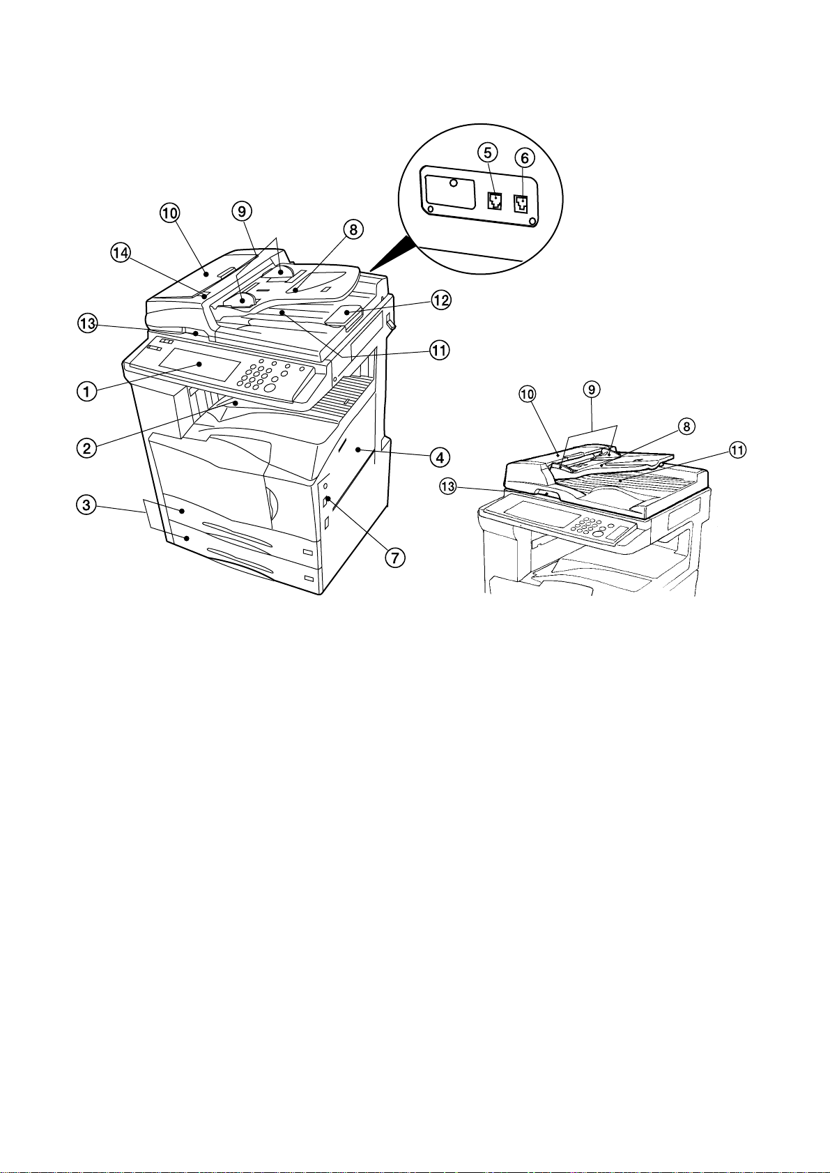
1-1-2 Parts names and their functions
(1) Copier
Figure 1-1-1
1 Operation panel .....................................Use the operation panel to perform the procedures required for fax
communication.
2 Fax storage section................................ Received documents are ejected and stored face-down in the fax storage
section. Up to 250 sheets can be stored in this section at one time.
3 Drawers.................................................. This fax machine comes standard with two drawers installed. Each drawer
can hold up to 500 sheets of plain paper (60 g/m2 - 105 g/m2).
4 Multi-Bypass ..........................................Paper can be set in the Multi-Bypass as well. In order to use the Multi-
Bypass, it is necessary to select "ON" under "Turning Manual Paper Feed
ON/OFF".
5 Telephone jack (T)..................................Use this jack to connect a separately purchased telephone to the fax.
6 Line jack (L) ...........................................Use this jack to connect the fax to a telephone line using the modular cord.
7 Main switch ............................................ Turn this switch ON ( | ) in order to perform fax and copy operations. The
message display will light and operation will be possible.
• Document Processor
There are 2 optional document processors available for use with this machine: the document processors for feeding onesided documents, and the duplex document processor for using both sides of 2-sided documents.
* Both the document processor and duple x document processor can be used with the 25 copies per minute machine.
However, only the duplex document processor can be used with the 35 copies per minute machine.
8 Document table ...................................... Set the documents you want to transmit on this table. Up to 70 sheets of up
to 11" x 8 1/2" [A4] size paper, or up to 50 sheets of 8 1/2" x 14" or 11" x 17"
[A3 or Folio] size paper, can be set at one time.
9 Document insert guides ......................... Adjust these guides to match the width of the documents.
10 Document processor reversing cover..... Open this cover if a document jams.
11 Document eject cover ............................Documents are ejected onto this cover after being scanned.
12 Eject guide .............................................Open this guide when transmitting documents of a large size such as 8 1/2" x
14" or 11" x 17" [A3 or Folio].
13 Document processor open/close lever...Operate this lever when opening and closing the document processor.
14 Document set indicator ..........................This indicator indicates the status of the documents set in the document
processor. Documents are set properly when the indicator is lit green.
Figure 1-1-2
1-1-4
Page 8
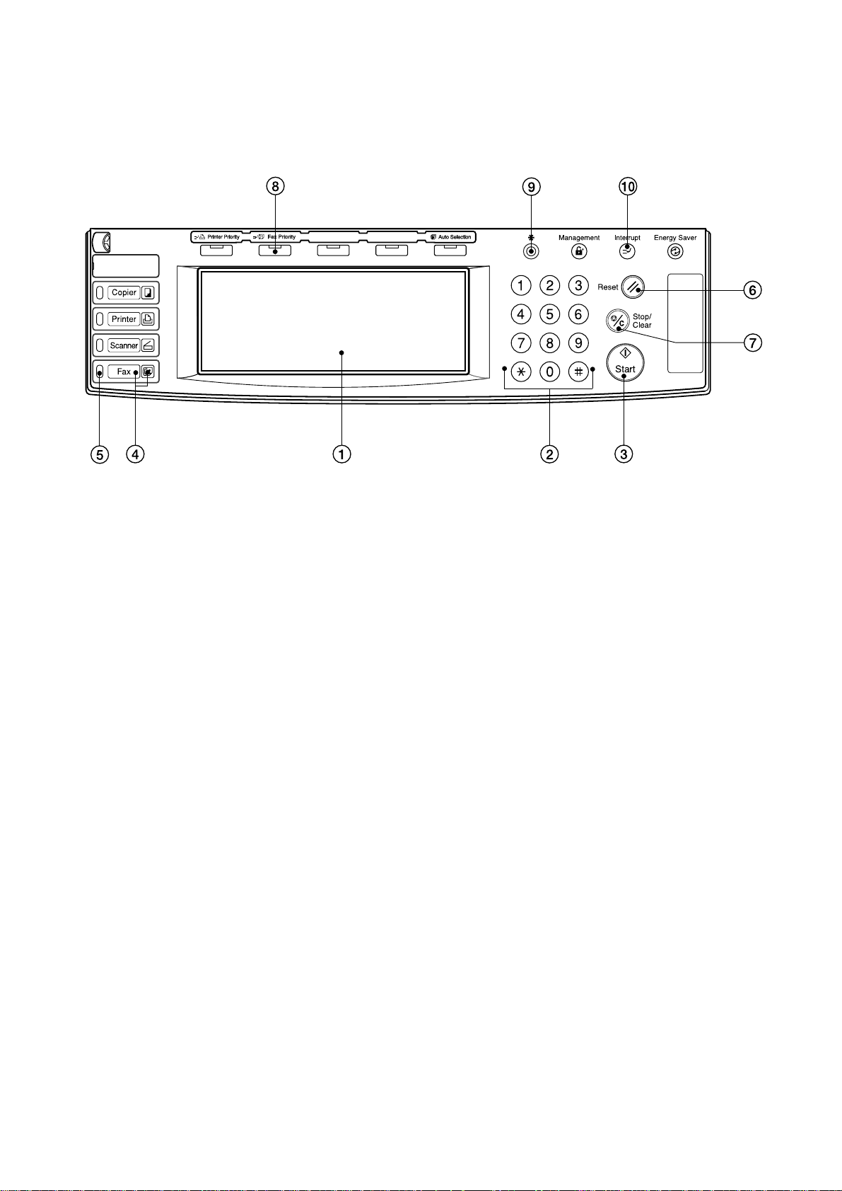
(2) Operation panel
3CM
Figure 1-1-3
1 Touch panel......................... Indicates operation procedures as well as trouble with the machine. Keys related to
operational procedures which appear on the touch panel with their name displayed are
indicated in this handbook within double quotation marks. In addition, you will be
instructed to "touch" any keys which appear on the touch panel rather than "press" them.
(Ex.: Touch the "xxx" key.)
2 Keypad................................ Use the keypad to enter fax numbers, etc.
* Even if your telephone service is for pulse dialing, press the star (*) key and any key
pressed on the keypad after that will transmit the related tone signal. (Inch version
only)
3 Start key.............................. Press this key when you want to initiate a fax communication.
4 Fax key/Fax indicator .......... Press this key when you want to switch between the Copy Operation and Fax Operation
modes. The Fax indicator is lit when the machine is in the Fax Operation mode.
5 Fax data indicator................ When received documents or other data are being stored in memory, this indicator will
flash and then light continuously.
6 Reset key ............................ Press this key when you want to cancel an operation in progress and have the touch
panel return to the initial mode settings.
7 Stop/Clear key..................... Press this key when you want to delete registered fax numbers or names, as well as
when you want to stop an operation in progress.
8 Fax Priority key ................... Press this key when you want to give priority to printing out a received fax during a copy
operation.
9 Default key .......................... Press this key when you want to perform settings related to the various default modes for
the fax functions of this machine.
Interrupt key/indicator lamp..
10
Press this key when you want to interrupt a fax reception in order to make copies. The
indicator lamp in the Interrupt key will light when the machine is in the Interrupt mode.
1-1-5
Page 9
3CM
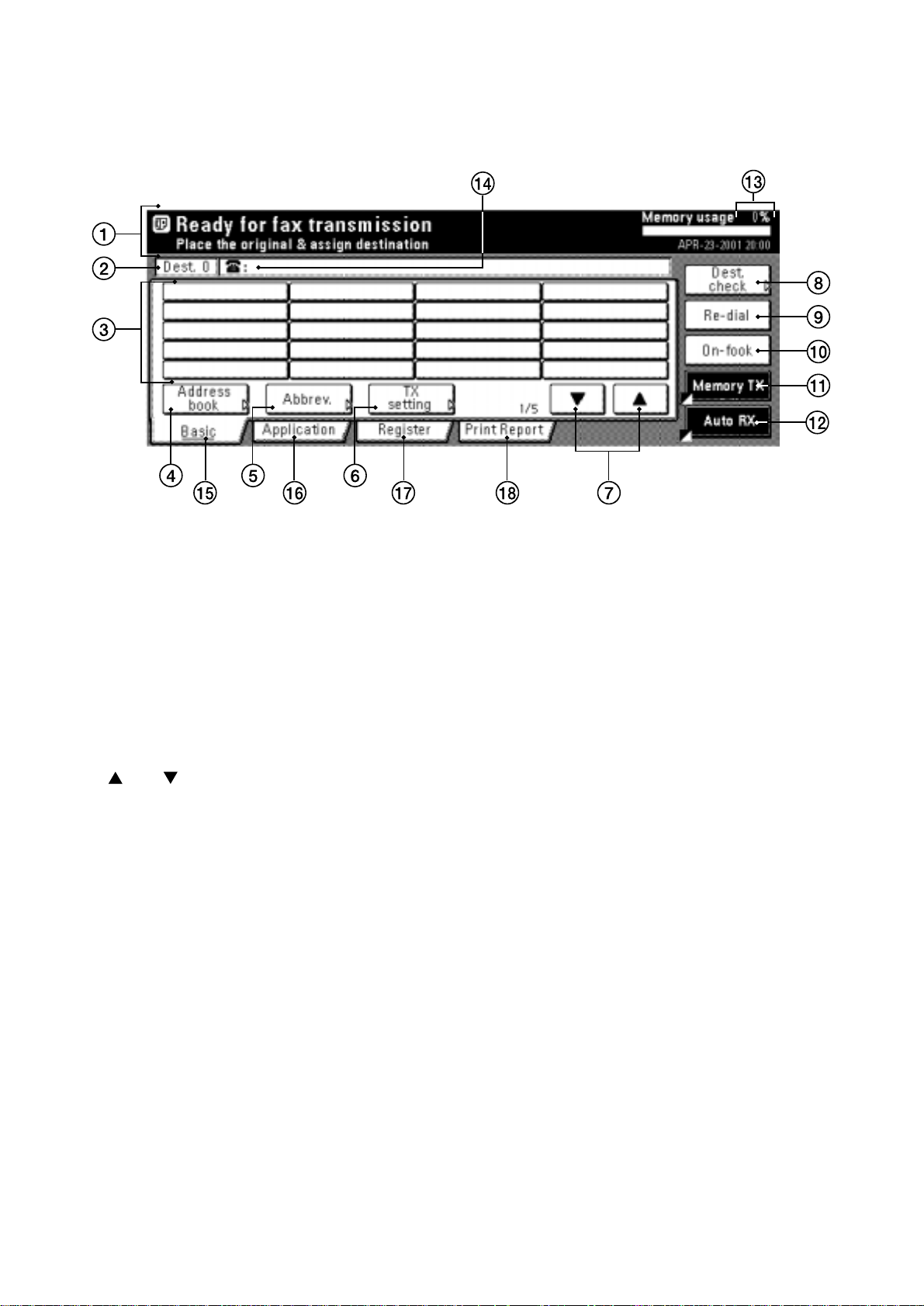
(3) Basic fax screen on the touch panel
The initial screen that appears in the touch panel when you press the Fax key in any other mode in order to change to the
Fax Operation mode is called the "basic fax screen". The following contains information on the basic keys which are
displayed in this screen and their functions.
Figure 1-1-4
1 Message display ........................... Current status, the next step in a procedure and error messages are shown in the
message display.
2 Number of destinations display..... The number of destinations that you have chosen to dial to is shown in this area.
3 Speed-dial keys............................. Keys that you have registered to function as either a one-touch key, a group dial
key (G), a program key (P) or a chain dial key (C) are displayed here.
4 "Address book" key....................... Touch this key when you want to use the address book.
5 "Abbrev." key ................................. Touch this key when you want to use the abbreviated number that a destination
number is registered under in order to dial that number.
6 "TX setting" key............................. Touch this key when you want to perform settings related to transmission
conditions such as the size of the documents to be transmitted, the image quality
of those documents, the contrast at which you want to send them and the time
when they should be sent. Once you press this key, the TX Setting screen will
appear.
" and " " cursor keys .............. Use these keys when you want to display speed-dial keys other than those which
7"
are currently displayed.
8 "Dest. check" key .......................... Touch this key when you have entered multiple destination fax numbers using
speed-dial keys, etc., and you want to check the list of those numbers.
9 "Re-dial" key.................................. Touch this key when you want to have the fax automatically redial the most
recently dialed number
10 "On-hook" key ............................... When a separately purchased telephone is connected to this fax machine and you
touch this key, you can dial a destination number without having to pick up the
receiver.
11 "Memory TX" / "Dir. Feed Tx" key.. When you want to switch between the Memory Transmission mode ("Memory Tx")
and the Direct Feed Transmission mode ("Dir. Feed Tx"). The mode will change
each time you touch this key.
12 Reception mode select key........... Touch this key when you want to select a different reception mode. The mode will
change each time you touch this key.
13 Memory bar................................... Indicates the amount of data stored in memory. As documents are being stored,
the bar will move towards "100%" indicating that the data stored in memory is
increasing. Once it reaches "100%", no more documents can be stored in memory.
14 Fax number display ....................... The number that you have entered to dial is displayed here.
15 "Basic" key .................................... Touch this key when you want to return to the basic fax screen.
16 "Application" key ........................... Touch this key when you want to use one of the various functions of this fax
machine such as polling, etc.
17 "Register" ["Registration"] key....... Touch this key when you want to perform one of the various registration
procedures of this fax machine.
18 "Print Report" key.......................... Touch this key when you want to print out one of the various reports or lists of this
fax machine.
1-1-6
Page 10
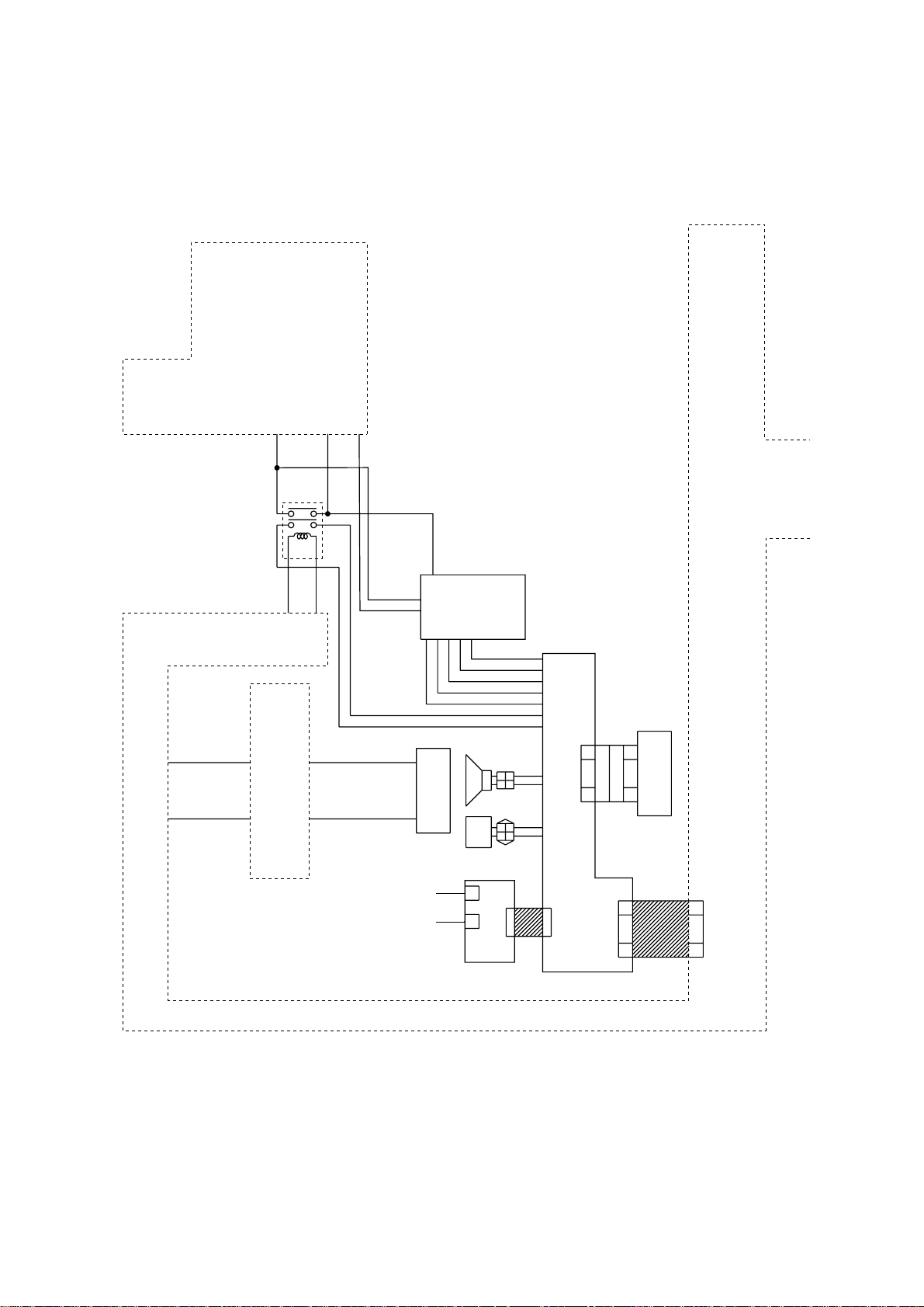
1-1-3 Mechanical construction
p
PSPCB
3CM
MPCB
TB4
LIVE(OUT)
MSW
MSW REM
3-4
OPCB
LIVE
24V
TB5
TB3
(IN)
RELAY OUT
RELAY IN
NEUTRAL IN
3-5
TB2
TB1
APSPCB
TB3
1-1
1-5
1-4
5.2V
GND
RELAY REM
FOPCB
12V
1-3
1-2
GND
SP
2112
SPEAKER
A.GND
8-6
8-5
8-3
8-1
8-7
8-8
8-9
7-1
CN4
7-2
(option)
Add-on memory
BATT
6-1
1
2
G(3.3V)
6-2
1
2
BUBAT
FCPCB
LINE
TEL/Handset
(option*)
NCUPCB
CN3
*O
CN1
tional for 120 V specifications only.
CN19
Figure 1-1-5
The fax system consists of the fax control PCB (FCPCB), NCU PCB (NCUPCB), auxiliary power source PCB (APSPCB),
fax operation unit PCB (FOPCB), speaker (SP), backup battery (BUBAT) and optional add-on memory.
1-1-7
Page 11

3CM
1-1-8
Page 12

1-2-1 Setting and registering data
After setting up the machine, set or register the following data.
(1) Settings
3CM
• Setting the type of telephone line*
1
Select the setting (pulse or tone) according to the type of telephone line to be used.
• Setting the document size for scanning from the document feeder
Select the setting (“Standard size original” or “Long original”) for scanning the original fed from the DF.
• Setting the paper feed selection mode
Select the paper feed mode (“Auto Selection mode”, “Fixed Size mode” or “Fixed Cassette mode”) for printing received
fax or reports.
• Setting 2-in-1 reception
Select whether or not to output two successively-received A5/8
• Setting the reception mode
Select an automatic reception mode (automatic fax reception, fax/telephone auto selection or D.R.D. reception*
1
/2" × 51/2" documents onto one A4R/81/2" × 11" page.
1
).
• Setting the memory fax forwarding
Select whether or not to perform memory fax forwarding.
• Setting report output condition
• Select the output condition for the management report (output or not output by department).
• Select the output condition for the activity report (output or not output after every 50 communications)
• Select the output condition for the transmission report (output or not output after each transmission)
• Select the output condition for the reception report (output or not output after each reception)
• Select the output condition for the timer communication report (output or not output after each timer programming).
• Setting the TTI transmission
Select whether or not to add the transmit terminal identifier (TTI) to the transmitting document.
• Setting reception date and time recording
Select whether or not to record the date and time on received documents.
• Setting the password check communication
Select whether or not to perform password check communication.
• Setting the speaker volume
Set the volume of the speaker in the on-hook mode (4 levels).
• Setting the alarm buzzer volume
Set the volume of the alarm that sounds during events such as when an error occurs (3 levels).
• Setting the monitoring volume
Set the volume for the sounds from the speaker (4 levels).
• Setting the bulletin board
Select whether or not to use the bulletin board during polling transmission.
• Setting duplex reception*
2
Select whether or not to print received documents on both sides of the paper.
• Setting the number of rings for automatic reception
Select the number of rings (1 to 15) that sound after call reception until fax data reception starts in the auto reception
mode.
• Setting the number of rings for TAD reception
Set the number of rings (1 to 15) that sound after call reception until fax data reception starts in the TAD reception
mode.
• Setting the number of rings for fax/telephone auto select mode*
1
Set the number of rings (0 to 15) that sound after call reception until fax data reception starts in the fax/telephone auto
select mode.
• Setting remote diagnosis
Set to take advantage of our remote diagnosis system.
• Setting the dial confirmation
Set whether or not to display information such as destination names, with functions that use one-touch keys (one-touch
dialing, group dialing and program dialing).
• Setting the default transmission mode
Select the transmission mode (memory transmission or direct feed transmission) to be used in the initial mode.
*1: For 120 V specifications only.
*2: When an optional duplex unit is installed.
1-2-1
Page 13

3CM
(2) Registration
• Date and time
Set the current date and time.
• Self station information
Register the self telephone number, self station name and self station ID.
• One-touch dialing
Register destination fax (telephone) numbers and names under one-touch keys. Up to 300 entries can be registered.
• Abbreviated dialing
Register destination fax (telephone) numbers and names to desired abbreviated numbers (001 to 300). Up to
300entries can be registered.
• Group dialing
Register multiple destination fax (telephone) numbers and names under a one-touch key for group dialing. Up to 300
entries can be registered.
• Program dialing
Register frequently used communication modes or fax numbers under one-touch keys. Up to 300 entries can be
registered.
• Chain dialing
Register chain numbers and names under one-touch keys. Up to 300 entries can be registered.
• Remote switching number
Change the remote switching number, which is set to “55” at the factory, for receiving faxes using the telephone
connected to the machine.
• Management password
Register a 4-digit password, which is set to “6482” at the factory, for encrypted communication.
• Cipher key password
Register a 16-digit cipher key password for encrypted communication.
• Encryption boxes
Register encryption boxes for receiving encrypted transmissions. Up to 20 boxes can be registered.
• Permit telephone numbers and IDs
Register the password (permit telephone number or ID) for password check communication.
• F-code confidential boxes
Register F-code confidential boxes for F-code based confidential communication. Up to 15 boxes can be registered.
• F-code relay boxes
Register F-code relay box for F-code based relay broadcast communication. Up to 15 boxes can be registered.
• Access codes
Register access codes for restricted access. Up to 50 codes can be registered.
1-2-2
Page 14
1-2-2 Installing the optional add-on memory
Add-on memory installation on the fax control PCB assembly requires the following parts:
8 MB add-on memory (P/N: 2AW6001)
<Procedure>
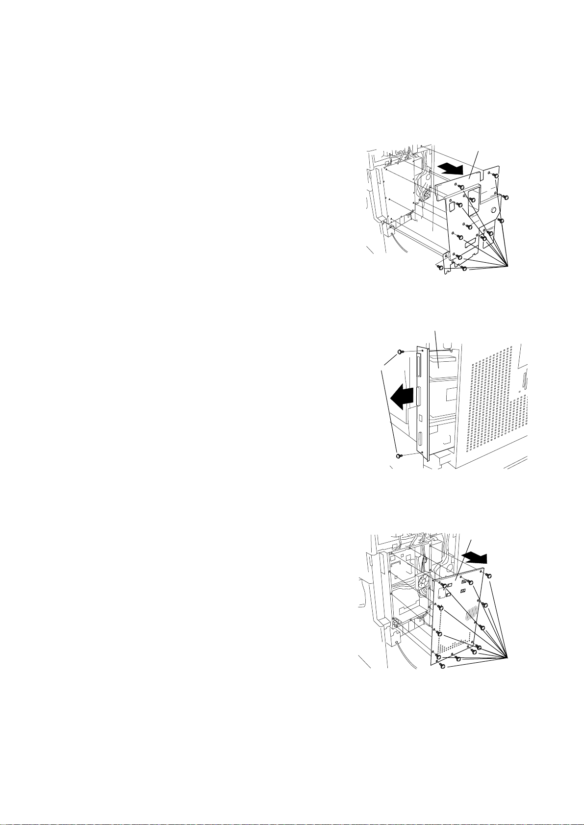
1. Remove 13 screws and take off the rear cover.
3CM
Rear cover
Screws
Figure 1-2-1
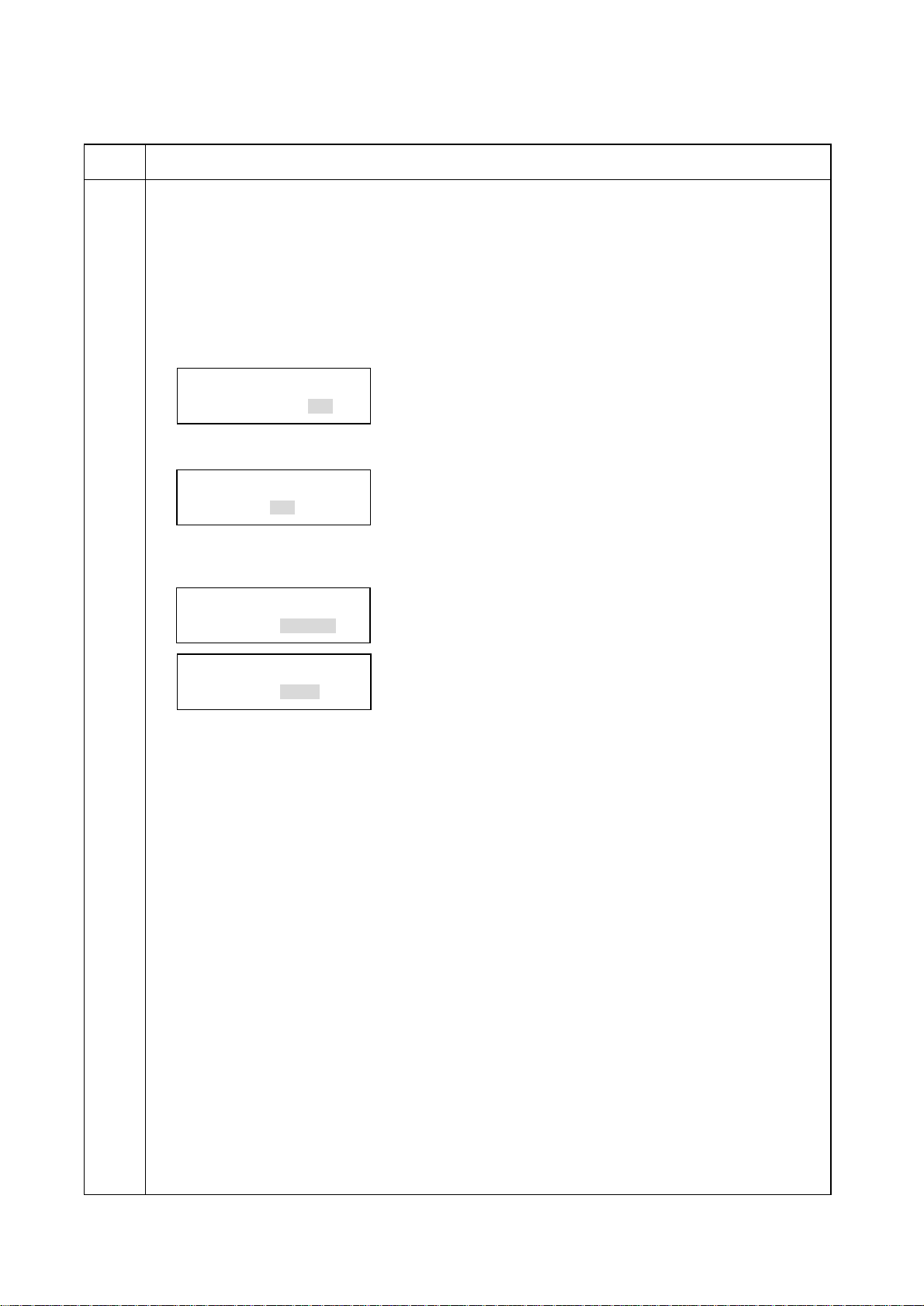
2. If the printing system is installed: Remove the 2 screws holding the
printer system in place, and pull the printing system out of the
controller box.
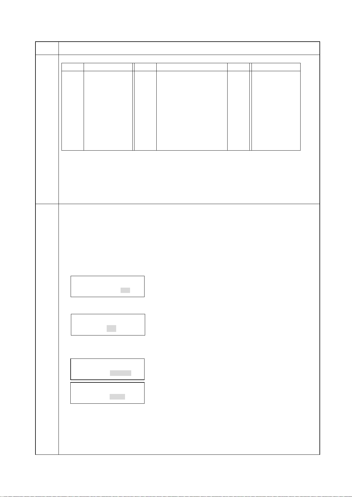
3. Remove 13 screws and take off the controller-box cover.
Printing system
Screws
Figure 1-2-2
Controller-box
cover
Figure 1-2-3
Screws
1-2-3
Page 15

3CM
4. Insert the Memory module DIMM (8MB) at an angle into the
memory slot on the fax board.
Important: The Memory module DIMM (8MB) must be installed
onto the fax board. Please be sure that you do not
install it onto the main PCB.
5. Push the free end of the module down toward the board.
6. Refit all removed parts.
Memory module DIMMMemory slot
Figure 1-2-4
1-2-4
Page 16

1-3-1 Maintenance mode
(1) Maintenance mode item list
3CM
Fax
Section
Item
No. setting*
U600 Initializing all data —
U601 Initializing permanent data —
U602 Setting factory defaults —
U603 Setting the user registration data
• Setting the self telephone number —
• Setting the type of telephone line —
• Setting the number of rings in the fax/telephone auto select mode —
• Setting remote diagnostic transmission —
U604 Clearing data
• Clearing transmission history —
• Initializing the management password —
• Initializing the F-code confidential box ID —
• Initializes the F-code relay box ID —
• Initializes the encription box ID —
U605 Setting the system (operational)
• Setting how to proceed if memory becomes full
during memory transmission —
• Setting an alarm for when reception is completed —
• Selecting if auto reduction in the auxiliary direction is to be performed —
• Setting the addition of an image to the report —
• Setting the error report display format —
• Setting the line-monitoring period —
• Setting the one-shot detection time for remote switching —
• Setting the continuous detection time for remote switching —
• Setting the initial condition of fax image scanning quality —
U606 Setting the system (operation unit and display)
• Setting the conditions under which an error indicator turns off —
• Setting the date format —
• Setting if the image scanning quality in fax mode is initialized —
• Setting if the scanning density in fax mode is initialized —
• Setting whether to skip unregistered abbreviated numbers
and one-touch key numbers on the list —
U607 Setting the system (communication 1)
• Setting the auto redialing interval —
• Setting the number of times of auto redialing —
• Setting the communication starting speed —
• Setting the reception speed —
• Setting the mode for remote switching —
• Setting the transmission intervals —
• Sets the loop current detection before dialing —
• Sets the DIS signal to 4 bytes —
U608 Setting transmission
• Setting the method to process errors —
• Setting the number of times of DIS signal reception —
• Setting the reference for RTN signal output —
• Setting the waiting period to prevent echo problem at the sender —
• Setting the waiting period to prevent echo problem at the receiver —
• Setting ECM transmission —
• Setting ECM reception —
• Setting the criteria for receiving a TCF signal 1 —
• Setting the frequency of the CED signal —
U609 Setting communication time
• Setting the T0 time-out time —
• Setting the T1 time-out time —
• Setting the T2 time-out time 69
• Setting the Ta time-out time 30
• Setting the Tb1 time-out time 20
• Setting the Tb2 time-out time 80
• Setting the Tc time-out time 60
• Setting the Td time-out time —
Maintenance item contents
Initial
1-3-1
Page 17

3CM
Section
Fax U610 Setting the modem output level
Item
No. setting
• Setting the modem output level —
• Adjusting the modem output level —
U611 G3 cable equalizer
• Setting the G3 transmission cable equalizer —
• Setting the G3 reception cable equalizer —
U612 Setting the modem detection level —
U613 Setting the DTMF output level
• Setting the DTMF (high-frequency group) output level —
• Setting the DTMF (low-frequency group) output level —
U614 Adjusting the DTMF output level
• Adjusting the DTMF (high-frequency group) output level —
• Adjusting the DTMF (low-frequency group) output level —
U615 Setting the NCU
• Setting the connection to PBX/PSTN —
• Setting PSTN dial tone detection —
• Setting busy tone detection —
• Setting for a PBX —
U616 Adjusting the ratio of make-to-break of dial pulses
• Make time (10 PPS) —
• Make time (20 PPS) —
U617 Outputting lists
• Settings list —
• Action list —
• Monitor list —
• Own-status report —
• Protocol list —
• One-touch dialing ECM setting list —
U650 Setting the system 1
• Setting the number of lines to be ignored when receiving a fax
at 100% magnification 3
• Setting the number of lines to be ignored when receiving a fax
in the auto reduction mode 3
• Setting the number of lines to be ignored when receiving a fax (A4R, letter)
in the auto reduction mode 3
• Setting the recording width for inch specifications —
• Setting automatic printing of the protocol list —
U651 Setting the system 2
• Setting the variation range in the auxiliary scanning direction
for rotation reception 3
• Setting the number of adjustment lines for automatic reduction 7
• Setting the number of adjustment lines for automatic reduction
when A4 paper is set 22
• Setting the number of adjustment lines for automatic reduction
when letter size paper is set 26
U660 Setting the system (communication 2)
• Setting the criteria for receiving a TCF signal 2 —
• Setting the short protocol transmission —
• Setting the reception of a short protocol transmission —
• Setting the CNG detection times in the fax/ telephone auto select mode —
• Turning ECM for one-touch dialing on/off —
U670 Setting the system (communication 3)
• Setting if V.34 transmission is available —
• Setting the V.34 symbol speed (3429 Hz) —
• Setting the V.34 symbol speed (3200 Hz) —
• Setting the V.34 symbol speed (3000 Hz) —
• Setting the V.34 symbol speed (2800 Hz) —
U680 Displaying the fax board ROM version —
Maintenance item contents
Initial
1-3-2
Page 18

3CM
Section
Fax
Others
Item
No. setting
U881 Using the flash-memory jig
• Saving data from SRAM into the jig —
• Writing data from the jig into RAM
• Writing the boot program into the jig
U894 Performing board test
• Performing tests on SRAM and DRAM —
• Performing tests on optional memory —
U992 Checking or clearing the printer/fax count —
Maintenance item contents
Initial
1-3-3
Page 19
3CM
(2) Contents of maintenance mode items
Maintenance
item No.
U600 Initializing all data
Description
Initializes software switches and all data in the SRAM on the f ax control PCB , according to the destination and
OEM.
Purpose
Used to initialize the fax control PCB.
Method
1. Press the start key. The screen for entering the destination code is displayed.
Enter a destination code using the numeric keys (refer to the destination code list on page 1-3-5 for the
destination code).
INI. ALL DATA
COUNTRY CODE:000
2. Press the start key. The screen for entering the OEM code is displayed.
There is no operation necessary on this screen.
INI. ALL DATA
OEM CODE:000
3. Press the start key. Data initialization starts. To cancel data initialization, press the stop/clear key.
4. After data initialization, the entered destination and OEM codes are displayed, and the ROM version is
displayed two seconds later.
Description
INI. ALL DATA
COMPLETED 000 000
INI. ALL DATA
COMPLETED V1.00
Caution
If initialized with "000" (code for Japan) entered as the destination code, service call code C082 (fax control
PCB problem) will be detected. Be sure to enter the correct destination code. If C082 (f ax control PCB problem)
is detected, press the COPY/F AX s witching k ey to put the machine in the cop y mode , open the front cov er and
then execute this maintenance item again to enter the correct destination code and initialize data.
1-3-4
Page 20
3CM
Maintenance
item No.
U600
(cont.)
U601 Initializing permanent data
Destination code list
Code
000
009
080
084
088
108
126
136
137
152
156
Description
Initializes software switches other than that for machine data on the fax control PCB according to the
destination and OEM.
Purpose
Used to initialize the fax control PCB without changing user registration data and factory settings.
Method
1. Press the start key. The screen for entering the destination code is displayed.
Enter a destination code using the numeric keys (refer to the destination code list on page 1-3-5 for the
destination code).
Destination
Japan
Australia
Hong Kong
Indonesia
Israel
Malaysia
New Zealand
Peru
Philippines
Middle East
Singapore
Code
159
169
181
242
243
253
Description
Destination
South Africa
Thailand
U.S.A.
South America
Saudi Arabia
CTR21 (European nations)
Italy
Germany
Spain
U.K.
Netherlands
Code
253
254
Destination
Sweden
France
Austria
Switzerland
Belgium
Denmark
Finland
Portugal
Ireland
Norway
Taiwan
INI. KEEP DATA
COUNTRY CODE:000
2. Press the start key. The screen for entering the OEM code is displayed.
There is no operation necessary on this screen.
INI. KEEP DATA
OEM CODE:000
3. Press the start key. Data initialization starts. To cancel data initialization, press the stop/clear key.
4. After data initialization, the entered destination and OEM codes are displayed, and the ROM version is
displayed two seconds later.
INI. KEEP DATA
COMPLETED 000 000
INI. KEEP DATA
COMPLETED V1.00
Caution
If initialized with "000" (code for Japan) entered as the destination code, service call code C082 (fax control
PCB problem) will be detected. Be sure to enter the correct destination code. If C082 (f ax control PCB problem)
is detected, press the COPY/F AX s witching k ey to put the machine in the cop y mode , open the front cov er and
then execute this maintenance item again to enter the correct destination code and initialize data.
1-3-5
Page 21
3CM
Maintenance
item No.
U602 Setting factory defaults
Description
Initializes software switches other than that f or machine data and the SRAM on the f ax control PCB , according
to the destination and OEM.
Purpose
Used to initialize the fax control PCB to the factory default.
Method
1. Press the start key. Data initialization starts. To cancel data initialization, press the stop/clear key.
2. After data initialization, the entered destination and OEM codes are displayed, and the ROM version is
displayed two seconds later.
INI. SHIP DATA
COMPLETED 000 000
INI. SHIP DATA
COMPLETED V1.00
Description
1-3-6
Page 22
3CM
Maintenance
item No.
U603 Setting the user registration data
Description
Makes user settings to enable the use of the copier as a fax.
Purpose
To be run after installation of the facsimile kit if necessary.
Start
1. Press the start key. The screen for selecting an item is displayed.
2. Press the appropriate item.
The screen for the selected item appears.
Display
SELF TEL No.
LINE TYPE
RINGS (F/T) #
REMOTE DIAG
Setting the self telephone number
1. Enter the telephone number using the numeric keys.
Up to 20 digits can be entered.
To correct the entered telephone number or to delete the stored telephone number, reset by pressing the
stop/clear key.
2. Press the start key.
3. To return to the screen for selecting an item, press the stop/clear key.
The item-selection screen does not reappear until registration or deletion processing is completed.
Setting the type of telephone line
1. Change the setting using the numeric keys.
Display
1: DTMF
2: 10
3: 20
2. Press the start key. The value is set.
3. To return to the screen for selecting an item, press the stop/clear key.
Setting the number of rings in the fax/telephone auto select mode
Use this if the user wishes to adjust the number of rings that occur before the unit switches into fax receiving
mode when fax/telephone auto-select is enabled.
1. Change the setting using the numeric keys.
Number of fax/telephone rings
DTMF
10 PPS
20 PPS
Sets the self telephone number.
Sets the type of telephone line.
Sets the number of rings in fax/telephone auto select mode.
Sets remote diagnostic transmission.
Description
Description
Description
Description
Setting range
0 to 15
If you set this to 0, the unit will start fax reception without any ringing.
2. Press the start key. The value is set.
3. To return to the screen for selecting an item, press the stop/clear key.
Setting remote diagnostic transmission
1. Enter 1 or 2 using the numeric keys to select if remote diagnostic transmission is to be enabled.
Display
1: ON
2: OFF
2. Press the start key. The value is set.
3. To return to the screen for selecting an item, press the stop/clear key.
Completion
Press the stop/clear key at the screen for selecting an item. The screen for selecting a maintenance item No. is
displayed.
Remote diagnostic transmission is enabled.
Remote diagnostic transmission is disabled.
Description
1-3-7
Page 23

3CM
Maintenance
item No.
U604 Clearing data
Description
Initializes data related to the fax transmission such as transmission history and IDs.
Purpose
Used to clear the transmission history or if an ID has been forgotten.
Method
1. Press the start key. The screen for selecting an item is displayed.
2. Press the appropriate item.
Initialization processing starts. When processing is finished, the screen displays "COMPLETED".
Display
COMM. REC
MANAGE PW
F-CODE ID
F-CODE ID
ENCRPT ID
3. To return to the screen for selecting an item, press the stop/clear key.
Completion
Press the stop/clear key at the screen for selecting an item. The screen for selecting a maintenance item No. is
displayed.
U605 Setting the system (operational)
Description
Makes settings for fax transmission regarding operation.
Start
1. Press the start key. The screen for selecting an item is displayed.
2. Press the appropriate item.
The screen for the selected item appears.
Clears the activity report, error list, action list, transmission history
of each department as listed on the department control report,
transmission history for displaying the transmission results,
document number, timer program information, protocol list, and
other transmission history such as image data, excluding items
regarding the machine variation adjustment.
Initializes the management password.
Initializes the F-code confidential box ID.
Initializes the F-code relay box ID.
Initializes the encription box ID.
Description
Description
Display
MEM. FULL
FIN. ALARM
AUTO REDU
ADD IMAGE
ERR. CODE
MONITOR
TIME (ONE)
TIME (CON)
RESOLUT
Setting how to proceed if memory becomes full during memory transmission
Used to select whether to send only stored data or to display an error indication and cancel transmission if
memory becomes full during memory transmission.
1. Enter 1 or 2 using the numeric keys to change the setting.
Display
1: CONT
2: STOP
2. Press the start key. The value is set.
3. To return to the screen for selecting an item, press the stop/clear key.
Sets how to proceed if memory becomes full
during memory transmission.
Sets an alarm for when reception is completed.
Selects if auto reduction in the auxiliary direction
is to be performed.
Sets for the addition of an image to the report.
Sets the error report display format.
Sets the line-monitoring period.
Sets the one-shot detection time for remote switching.
Sets the continuous detection time for remote switching.
Sets the initial condition of fax image scanning quality.
Whether to continue memory transmission or to
clear the memory can be selected by the user.
Memory is forcibly cleared.
Description
Description
1-3-8
Page 24
3CM
Maintenance
item No.
U605
(cont.)
Setting an alarm for when reception is completed
1. Enter 1 or 2 using the numeric keys to change the setting.
2. Press the start key. The value is set.
3. To return to the screen for selecting an item, press the stop/clear key.
Selecting if auto reduction in the auxiliary direction is to be performed
Sets whether to receive a long document by automatically reducing it in the auxiliary direction or at 100%
magnification.
1. Enter 1 or 2 using the numeric keys to change the setting.
2. Press the start key. The value is set.
3. To return to the screen for selecting an item, press the stop/clear key.
Setting the addition of an image to the report
Selects if an image is to be added to the transmission report.
1. Enter 1 or 2 using the numeric keys to change the setting.
Display
1: ON
2: OFF
Display
1: ON
2: OFF
Display
1: ON
2: OFF
Description
Description
An alarm rings.
An alarm does not ring.
Description
Auto reduction is performed if the received
document is longer than the fax paper.
Auto reduction is not performed.
Description
Image added.
Image not added.
2. Press the start key. The value is set.
3. To return to the screen for selecting an item, press the stop/clear key.
Setting the error report display format
Selects the format of the transmission report when a transmission error occurs.
1. Change the setting using the numeric keys.
Display
1: WORDS
2: CODE
3: MIX
Records an error message (BUSY, OK, ERROR or STOP).
Records a six-digit error code.
Records either an error message or code.
Description
2. Press the start key. The value is set.
3. To return to the screen for selecting an item, press the stop/clear key.
Setting the line-monitoring period
Sets the period to monitor the line. By monitoring a transmission from the start to the end, it can be checked
whether the transmission was correct or not.
1. Change the setting using the numeric keys.
Display
1: END
2: DIS
Until transmission is completed.
After dialing is completed until reception of a DIS signal.
Description
2. Press the start key. The value is set.
3. To return to the screen for selecting an item, press the stop/clear key.
Setting the one-shot detection time for remote switching
Sets the detection time when one-shot detection is selected for remote switching. (This setting item will be
displayed, but the setting made is ineffective.)
1. Change the setting using the numeric keys.
Description
One-shot detection time for remote switching
Setting range
0 to 255 ms
2. Press the start key. The value is set.
3. To return to the screen for selecting an item, press the stop/clear key.
1-3-9
Page 25
3CM
Maintenance
item No.
U605
(cont.)
U606 Setting the system (operation unit and display)
Setting the continuous detection time for remote switching
Sets the detection time when continuous detection is selected for remote switching. (This setting item will be
displayed, but the setting made is ineffective.)
1. Change the setting using the numeric keys.
Description
Continuous detection time for remote switching
2. Press the start key. The value is set.
3. To return to the screen for selecting an item, press the stop/clear key.
Setting the initial condition of fax image scanning quality
Set to the resolution that is most frequently used by the user.
1. Change the setting using the numeric keys.
Display
1: S
2: F
3: SF
4: UF
2. Press the start key. The value is set.
3. To return to the screen for selecting an item, press the stop/clear key.
Completion
Press the stop/clear key at the screen for selecting an item. The screen for selecting a maintenance item No. is
displayed.
Description
Makes settings for fax transmission regarding the operation unit and display.
Start
1. Press the start key. The screen for selecting an item is displayed.
Note: Since this model does not pro vide LED error indicators, this setting has no affect on actual oper ation.
Display
ALARM LED OFF
DATE PATTERN
RESO. LOCK
DENS. LOCK
REPORT SKIP
Setting the conditions under which an error indicator turns off
1. Enter 1 or 2 using the numeric keys to change the setting.
Display
1: RESET
2: COMM
2. Press the start key. The value is set.
3. To return to the screen for selecting an item, press the stop/clear key.
Setting the date format
Selects the date format on the respective reports and sender’s information record.
1. Change the setting using the numeric keys.
Display
1: YMD
2: MDY
3: DMY
2. Press the start key. The value is set.
3. To return to the screen for selecting an item, press the stop/clear key.
Description
Standard
Fine
Super fine
Ultra fine
Description
Sets the conditions under which an error indicator turns off.
Sets the date format.
Sets if the image scanning quality in fax mode is initialized.
Sets if the scanning density in fax mode is initialized.
Sets whether to skip unregistered abbreviated numbers
and one-touch key numbers on the list.
Description
An error indicator turns off only when the
reset key is pressed.
An error indicator turns off when any key is
pressed, an original is inserted or the next
transmission is started.
Order
Year/month/day
Month/day/year
Day/month/year
Description
Setting range
0 to 255 ms
1-3-10
Page 26

3CM
Maintenance
item No.
U606
(cont.)
Setting if the image scanning quality in fax mode is initialized
Sets if the resolution is to be initialized when fax operation is complete.
1. Enter 1 or 2 using the numeric keys to change the setting.
2. Press the start key. The value is set.
3. To return to the screen for selecting an item, press the stop/clear key.
Setting if the scanning density in fax mode is initialized
Sets if the scanning density is initialized when fax operation is complete.
1. Enter 1 or 2 using the numeric keys to change the setting.
2. Press the start key. The value is set.
3. To return to the screen for selecting an item, press the stop/clear key.
Setting whether to skip unregistered abbreviated numbers and one-touch key numbers on the list
Sets whether to skip unregistered abbreviated numbers and one-touch key numbers on the list.
1. Enter 1 or 2 using the numeric keys to change the setting.
Display
1: ON
2: OFF
Display
1: ON
2: OFF
Display
1: ON
2: OFF
Description
Description
Resolution is initialized.
Resolution is not initialized.
Description
Density is initialized.
Density is not initialized.
Description
Unregistered numbers are skipped.
Unregistered numbers are not skipped.
2. Press the start key. The value is set.
3. To return to the screen for selecting an item, press the stop/clear key.
Completion
Press the stop/clear key at the screen for selecting an item. The screen for selecting a maintenance item No. is
displayed.
1-3-11
Page 27

3CM
Maintenance
item No.
U607 Setting the system (communication 1)
Description
Makes settings for fax transmission regarding the communication.
Start
1. Press the start key. The screen for selecting an item is displayed.
2. Press the appropriate item.
The screen for the selected item appears.
Display
INTERVAL
TIMES
TX SPEED
RX SPEED
REMOTE
CALL INT
DC LOOP
DIS 4BYTE
Setting the auto redialing interval
Change the setting to prevent the following problems: fax transmission is not possible due to too short redial
interval, or fax transmission takes too much time to complete due to too long redial interval.
1. Change the setting using the numeric keys.
Redialing interval
Sets the auto redialing interval.
Sets the number of times of auto redialing.
Sets the communication starting speed.
Sets the reception speed.
Sets the mode for remote switching.
Sets the transmission intervals.
Sets the loop current detection before dialing.
Sets the DIS signal to 4 bytes.
Description
Description
Description
Setting range
1 to 9 min.
2. Press the start key. The value is set.
3. To return to the screen for selecting an item, press the stop/clear key.
Setting the number of times of auto redialing
1. Change the setting using the numeric keys.
Description
Number of redialing
When set to 0, no redialing is performed.
2. Press the start key. The value is set.
3. To return to the screen for selecting an item, press the stop/clear key.
Setting the communication starting speed
Sets the initial communication speed when starting transmission. When the destination unit has V.34 capability,
V.34 is selected for transmission, regardless of this setting.
1. Change the setting using the numeric keys.
Display
1: 144
2: 96
3: 48
4: 24
2. Press the start key. The value is set.
3. To return to the screen for selecting an item, press the stop/clear key.
Setting the reception speed
Sets the reception speed that the sender is informed of using the DIS or NSF signal. When the destination unit
has V.34 capability, V.34 is selected, regardless of the setting.
1. Change the setting using the numeric keys.
Display
1: 144
2: 96
3: 48
4: 24
2. Press the start key. The value is set.
3. To return to the screen for selecting an item, press the stop/clear key.
V.17, 14400 bps
V.17, 9600 bps
V.27ter, 4800 bps
V.27ter, 2400 bps
V.17, V.33, V.29, V.27ter
V.29, V.27ter
V.27ter
V.27ter (fallback only)
Description
Description
Setting range
0 to 9
1-3-12
Page 28

3CM
Maintenance
item No.
U607
(cont.)
Setting the mode for remote switching
Sets the signal detection method for remote switching. Be sure to change the setting according to the type of
telephone connected to the machine.
1. Enter 1 or 2 using the numeric keys to change the setting.
2. Press the start key. The value is set.
3. To return to the screen for selecting an item, press the stop/clear key.
Setting the transmission intervals
Sets the minimum time required for connection to the line for the next transmission after the previous
transmission was completed. Change the setting if transmission problems occur during multi-transmission,
such as broadcasting and polling transmission, or reserved transmission.
1. Change the setting using the numeric keys.
2. Press the start key. The value is set.
3. To return to the screen for selecting an item, press the stop/clear key.
Setting the loop current detection before dialing
Sets if the loop current detection is performed before dialing.
1. Enter 1 or 2 using the numeric keys to change the setting.
2. Press the start key. The value is set.
3. To return to the screen for selecting an item, press the stop/clear key.
Setting the DIS signal to 4 bytes
Sets if bit 33 and later bits of the DIS/DTC signal are sent.
1. Enter 1 or 2 using the numeric keys to change the setting.
2. Press the start key. The value is set.
3. To return to the screen for selecting an item, press the stop/clear key.
Completion
Press the stop/clear key at the screen for selecting an item. The screen for selecting a maintenance item No. is
displayed.
1: ONE
2: CONT
Display
1: 10
2: 30
3: 70
4: 120
1: ON
2: OFF
1: ON
2: OFF
Display
Display
Display
Description
Description
One-shot detection
Continuous detection
Description
10 s
30 s
70 s
120 s
Description
Performs loop current detection before dialing.
Does not perform loop current detection before dialing.
Description
Bit 33 and later bits of the DIS/DTC signal are not sent.
Bit 33 and later bits of the DIS/DTC signal are sent.
1-3-13
Page 29

3CM
Maintenance
item No.
U608 Setting transmission
Description
Makes settings regarding fax transmission.
Start
1. Press the start key. The screen for selecting an item is displayed.
2. Press the appropriate item.
The screen for the selected item appears.
Display
ERROR
DIS-2 RES
RTN CHECK
TX ECHO
RX ECHO
ECM TX
ECM RX
TCF CHECK
CED FREQ.
Setting the method to process errors
Selects if transmission is to be treated as an error if an RTN or PIN signal is received. If it is treated as an error,
an alarm sounds and a transmission report is output.
1. Enter 1 or 2 using the numeric keys to change the setting.
Display
1: OK
2: ERROR
Description
Description
Sets the method to process errors.
Sets the number of times of DIS signal reception.
Sets the reference for RTN signal output.
Sets the waiting period to prevent echo problems at the sender.
Sets the waiting period to prevent echo problems at the receiver.
Sets ECM transmission.
Sets ECM reception.
Sets the criteria for receiving a TCF signal 1.
Sets the frequency of the CED signal.
Description
Transmission is not treated as an error.
Transmission is treated as an error.
2. Press the start key. The value is set.
3. To return to the screen for selecting an item, press the stop/clear key.
Setting the number of times of DIS signal reception
Sets the number of times to receive the DIS signal to once or twice. Used as one of the correction measures for
transmission errors and other problems.
1. Enter 1 or 2 using the numeric keys to change the setting.
Display
1: ONCE
2: TWICE
2. Press the start key. The value is set.
3. To return to the screen for selecting an item, press the stop/clear key.
Setting the reference for RTN signal output
Sets the error line rate as the reference for R TN signal output. If tr ansmission errors occur frequently due to the
quality of the line, they can be reduced by lowering this setting.
1. Change the setting using the numeric keys.
Display
1: 5
2: 10
3: 15
4: 20
2. Press the start key. The value is set.
3. To return to the screen for selecting an item, press the stop/clear key.
Responds to the first signal.
Responds to the second signal.
Error line rate of 5%
Error line rate of 10%
Error line rate of 15%
Error line rate of 20%
Description
Description
1-3-14
Page 30

3CM
Maintenance
item No.
U608
(cont.)
Setting the waiting period to prevent echo problems at the sender
Sets the period before a DCS signal is sent after a DIS signal is received. Used when problems occur due to
echoes at the sender.
1. Enter 1 or 2 using the numeric keys to change the setting.
2. Press the start key. The value is set.
3. To return to the screen for selecting an item, press the stop/clear key.
Setting the waiting period to prevent echo problems at the receiver
Sets the period before an NSF, CSI or DIS signal is sent after a CED signal is received. Used when problems
occur due to echoes at the receiver.
1. Enter 1 or 2 using the numeric keys to change the setting.
2. Press the start key. The value is set.
3. To return to the screen for selecting an item, press the stop/clear key.
Setting ECM transmission
To be set to OFF when reduction of transmission costs is of higher priority than image quality.
1. Enter 1 or 2 using the numeric keys to change the setting.
Display
1: 500
2: 300
Display
1: 500
2: 75
Display
1: ON
2: OFF
Description
Description
Sends a DCS 500 ms after receiving a DIS.
Sends a DCS 300 ms after receiving a DIS.
Description
Sends an NSF, CSI or DIS 500 ms after receiving a CED.
Sends an NSF, CSI or DIS 75 ms after receiving a CED.
Description
ECM transmission is enabled.
ECM transmission is disabled.
2. Press the start key. The value is set.
3. To return to the screen for selecting an item, press the stop/clear key.
Setting ECM reception
To be set to OFF when reduction of transmission costs is of higher priority than image quality.
1. Enter 1 or 2 using the numeric keys to change the setting.
Display
1: ON
2: OFF
2. Press the start key. The value is set.
3. To return to the screen for selecting an item, press the stop/clear key.
Setting the criteria for receiving a TCF signal 1
Sets the maximum number of error bytes judged acceptable when receiving a TCF signal. Used as a measure
to ease transmission conditions if transmission errors occur.
1. Change the setting using the numeric keys.
Number of allowed error bytes when detecting TCF
2. Press the start key. The value is set.
3. To return to the screen for selecting an item, press the stop/clear key.
ECM reception is enabled.
ECM reception is disabled.
Description
Description
Setting range
0 to 255
1-3-15
Page 31

3CM
Maintenance
item No.
U608
(cont.)
U609 Setting communication time
Setting the frequency of the CED signal
Sets the frequency of the CED signal. Used as one of the measures to improve transmission performance for
international communications.
1. Enter 1 or 2 using the numeric keys to change the frequency.
Display
1: 2100
2: 1100
2. Press the start key. The value is set.
3. To return to the screen for selecting an item, press the stop/clear key.
Completion
Press the stop/clear key at the screen for selecting an item. The screen for selecting a maintenance item No. is
displayed.
Description
Sets the time-out time for fax transmission.
Purpose
Used mainly to improve transmission performance for international communications.
Start
1. Press the start key. The screen for selecting an item is displayed.
2. Press the appropriate item.
The screen for the selected item appears.
Display
T0
T1
T2
Ta
Tb1
Tb2
Tc
Td
Setting the T0 time-out time
Sets the time before detecting a DIS signal after a dialing signal is sent. Depending on the quality of the
exchange, or when the auto select function is selected at the destination unit, a line can be disconnected.
Change the setting to prevent this problem.
1. Change the setting using the numeric keys.
T0 time-out time
2100 Hz
1100 Hz
Sets the T0 time-out time.
Sets the T1 time-out time.
Sets the T2 time-out time.
Sets the Ta time-out time.
Sets the Tb1 time-out time.
Sets the Tb2 time-out time.
Sets the Tc time-out time.
Sets the Td time-out time.
Description
Description
Frequency of the CED signal
Description
Setting range
30 to 90 s
1-3-16
2. Press the start key. The value is set.
3. To return to the screen for selecting an item, press the stop/clear key.
Setting the T1 time-out time
Sets the time before receiving the correct signal after call reception. No change is necessary for this
maintenance item.
1. Change the setting using the numeric keys.
Description
T1 time-out time
2. Press the start key. The value is set.
3. To return to the screen for selecting an item, press the stop/clear key.
Setting range
30 to 90 s
Page 32

3CM
Maintenance
item No.
U609
(cont.)
Setting the T2 time-out time
The T2 time-out time decides the following.
• From CFR signal output to image data reception
• From image data reception to the next signal reception
• In ECM, from RNR signal detection to the next signal reception
1. Change the setting using the numeric keys.
2. Press the start key. The value is set.
3. To return to the screen for selecting an item, press the stop/clear key.
Setting the Ta time-out time
In the fax/telephone auto select mode, sets the time to continue ringing an operator through the connected
telephone after receiving a call as a fax machine (see figure 1-3-1). A fax signal is received within the Ta set
time, or the fax mode is selected automatically when the time elapses. In fax/telephone auto select mode,
change the setting when fax reception is unsuccessful or a telephone fails to receive a call.
1. Change the setting using the numeric keys.
2. Press the start key. The value is set.
3. To return to the screen for selecting an item, press the stop/clear key.
Description
T2 time-out time
Description
Ta time-out time
Description
Setting range
Initial setting
Change in value per step
1 to 255 69 100 ms
Setting range
Initial setting
1 to 255 s 30
Ring detection
Tb1
Line connection
as a fax machine
Ring back tone send start
Tb2
Rings
Ta
Start of fax reception
Figure 1-3-1 Ta/Tb1/Tb2 time-out time
Setting the Tb1 time-out time
In the fax/telephone auto select mode, sets the time to start sending the ring back tone after receiving a call as
a fax machine (see figure 1-3-1). In fax/telephone auto select mode, change the setting when fax reception is
unsuccessful or a telephone fails to receive a call.
1. Change the setting using the numeric keys.
Description
Tb1 time-out time
Setting range
1 to 255 20 100 ms
Initial setting
Change in value per step
2. Press the start key. The value is set.
3. To return to the screen for selecting an item, press the stop/clear key.
Setting the Tb2 time-out time
In the fax/telephone auto select mode, sets the time to start ringing an operator through the connected
telephone after receiving a call as a fax machine (see figure 1-3-1). In the fax/telephone auto select mode,
change the setting when fax reception is unsuccessful or a telephone fails to receive a call.
1. Change the setting using the numeric keys.
Description
Tb2 time-out time
Setting range
1 to 255 80 100 ms
Initial setting
Change in value per step
2. Press the start key. The value is set.
3. To return to the screen for selecting an item, press the stop/clear key.
1-3-17
Page 33

3CM
Maintenance
item No.
U609
(cont.)
Setting the Tc time-out time
In the TAD mode, set the time to check if there are any triggers for shifting to fax reception after a connected
telephone receives a call. Only the telephone function is available if shifting is not made within the set Tc time .
In the TAD mode, change the setting when fax reception is unsuccessful or a telephone fails to receive a call.
1. Change the setting using the numeric keys.
2. Press the start key. The value is set.
3. To return to the screen for selecting an item, press the stop/clear key.
Setting the Td time-out time
Sets the length of the time required to determine silent status (fax), one of the triggers for Tc time chec k. In the
T AD mode , change the setting when f ax reception is unsuccessful or a telephone fails to receiv e a call. Be sure
not to set it too short; otherwise, the mode may be shifted to fax while the unit is being used as a telephone.
1. Change the setting using the numeric keys.
2. Press the start key. The value is set.
3. To return to the screen for selecting an item, press the stop/clear key.
Completion
Press the stop/clear key at the screen for selecting an item. The screen for selecting a maintenance item No. is
displayed.
Description
Tc time-out time
Description
Td time-out time
Setting range
1 to 255 s 60
Setting range
1 to 255 s
Description
Initial setting
1-3-18
Page 34

3CM
Maintenance
item No.
U610 Setting the modem output level
Description
Sets the modem output level.
Start
1. Press the start key. The screen for selecting an item is displayed.
2. Press the appropriate item.
The screen for the selected item appears.
Display
SGL LEVEL MODEM
SGL OUTPUT ADJ
Setting the modem output level
To be set when installing the machine in order to adapt to the line characteristics.
1. Change the setting using the numeric keys.
Description
Modem output level
2. Press the start key. The value is set.
3. To return to the screen for selecting an item, press the stop/clear key.
Adjusting the modem output level
No change is necessary from the factory default.
1. Change the setting using the numeric keys.
Setting
12
11
10
9
8
7
6
5
4
2. Press the start key. The value is set.
3. To return to the screen for selecting an item, press the stop/clear key.
Completion
Press the stop/clear key at the screen for selecting an item. The screen for selecting a maintenance item No. is
displayed.
1.0 dBm
0.75 dBm
0.5 dBm
0.25 dBm
0 dBm
–0.25 dBm
–0.5 dBm
–0.75 dBm
–1.0 dBm
Description
Description
Sets the modem output level.
Adjusts the modem output level.
Setting range
4 to 12
Output level
1-3-19
Page 35

3CM
Maintenance
item No.
U611 G3 cable equalizer
Description
Sets the G3 cable equalizer.
Start
1. Press the start key. The screen for selecting an item is displayed.
2. Press the appropriate item.
The screen for the selected item appears.
Display
REG. G3 TX EQR
REG. G3 RX EQR
Setting the G3 transmission cable equalizer
Perform the following adjustment to make the equalizer compatible with the line characteristics.
1. Change the setting using the numeric keys.
Display
1: 0
2: 18
3: 36
4: 72
2. Press the start key. The value is set.
3. To return to the screen for selecting an item, press the stop/clear key.
Setting the G3 reception cable equalizer
Perform the following adjustment to make the equalizer compatible with the line characteristics.
1. Change the setting using the numeric keys.
Display
1: 0
2: 18
3: 36
4: 72
2. Press the start key. The value is set.
3. To return to the screen for selecting an item, press the stop/clear key.
Completion
Press the stop/clear key at the screen for selecting an item. The screen for selecting a maintenance item No. is
displayed.
Description
Description
Sets the G3 transmission cable equalizer.
Sets the G3 reception cable equalizer.
Description
0 km
1.8 km
3.6 km
7.2 km
Description
0 km
1.8 km
3.6 km
7.2 km
1-3-20
Page 36

3CM
Maintenance
item No.
U612 Setting the modem detection level
Description
Sets the modem detection level.
Purpose
Used to improve the transmission performance when a low quality line is used.
Method
Press the start key. The current setting is displayed.
Setting
1. Change the setting using the numeric keys.
Display
1: 33
2: 38
3: 43
4: 47
2. Press the start key. The value is set.
Completion
Press the stop/clear key. The screen for selecting a maintenance item No. is displayed.
U613 Setting the DTMF output level
Description
Sets the DTMF output level of a push-button dial telephone.
Purpose
Used if problems occur when sending a signal with a push-button dial telephone.
Start
1. Press the start key. The screen for selecting an item is displayed.
2. Press the appropriate item.
The screen for the selected item appears.
–33 dBm
–38 dBm
–43 dBm
–47 dBm
Description
Description
Display
DTMF TX LEVEL (H)
DTMF TX LEVEL (L)
Setting
1. Change the setting using the numeric keys.
Description
DTMF (high-/low-frequency group) output level
E.g.: When set to 8, the DTMF output level is –8 dBm.
2. Press the start key. The value is set.
3. To return to the screen for selecting an item, press the stop/clear key.
Completion
Press the stop/clear key at the screen for selecting an item. The screen for selecting a maintenance item No. is
displayed.
Sets the DTMF (high-frequency group) output level.
Sets the DTMF (low-frequency group) output level.
Description
Setting range
0 to 255
1-3-21
Page 37

3CM
Maintenance
item No.
U614 Adjusting the DTMF output level
Description
Adjusts the DTMF output level of a push-button dial telephone.
Purpose
No change is necessary from the factory default.
Start
1. Press the start key. The screen for selecting an item is displayed.
2. Press the appropriate item.
The screen for the selected item appears.
Display
SGL LVL DTMF (H)
SGL LVL DTMF (L)
Setting
1. Change the setting using the numeric keys.
Setting
12
11
10
9
8
7
6
5
4
2. Press the start key. The value is set.
3. To return to the screen for selecting an item, press the stop/clear key.
Completion
Press the stop/clear key at the screen for selecting an item. The screen for selecting a maintenance item No. is
displayed.
DTMF (high-/low-frequency group) output level
2.0 dBm
1.5 dBm
1.0 dBm
0.5 dBm
0 dBm
–0.5 dBm
–1.0 dBm
–1.5 dBm
–2.0 dBm
Description
Description
Adjusts the DTMF (high-frequency group) output level.
Adjusts the DTMF (low-frequency group) output level.
1-3-22
Page 38

3CM
Maintenance
item No.
U615 Setting the NCU
Description
Makes setting regarding the network control unit (NCU).
Purpose
To be set when installing the facsimile kit.
Start
1. Press the start key. The screen for selecting an item is displayed.
2. Press the appropriate item.
The screen for the selected item appears.
Display
EXCHANGE
DIAL TONE
BUSY TONE
PBX SETTING
Setting the connection to PBX/PSTN
Selects if a fax is to be connected to either a PBX or public switched telephone network.
1. Enter 1 or 2 using the numeric keys to change the setting.
Display
1: PSTN
2: PBX
2. Press the start key. The value is set.
3. To return to the screen for selecting an item, press the stop/clear key.
Setting PSTN dial tone detection
Selects if the dial tone is detected to check the telephone is off the hook when a fax is connected to a public
switched telephone network.
1. Enter 1 or 2 using the numeric keys to change the setting.
Display
1: ON
2: OFF
2. Press the start key. The value is set.
3. To return to the screen for selecting an item, press the stop/clear key.
Setting busy tone detection
When a fax signal is sent, sets whether the line is disconnected immediately after a busy tone is detected, or
the busy tone is not detected and the line remains connected until T0 time-out time.
Fax transmission ma y fail due to incorrect busy tone detection. When set to 2, this problem may be pre v ented.
However, the line is not disconnected within the T0 time-out time even if the destination line is busy.
1. Enter 1 or 2 using the numeric keys to change the setting.
Display
1: ON
2: OFF
2. Press the start key. The value is set.
3. To return to the screen for selecting an item, press the stop/clear key.
Description
Description
Sets the connection to PBX/PSTN.
Sets PSTN dial tone detection.
Sets busy tone detection.
Setting for a PBX.
Description
Connected to the public switched telephone network.
Connected to a PBX.
Description
Detects the dial tone.
Does not detect the dial tone.
Description
Detects busy tone.
Does not detect busy tone.
1-3-23
Page 39

3CM
Maintenance
item No.
U615
(cont.)
U616 Adjusting the ratio of make-to-break of dial pulses
Setting for a PBX
Selects the mode to connect an outside call when connected to a PBX.
According to the type of the PBX connected, select the mode to connect an outside call.
1. Change the setting using the numeric keys.
Display
1: EARTH
2: FLS
3: LOOP
2. Press the start key. The value is set.
3. To return to the screen for selecting an item, press the stop/clear key.
Completion
Press the stop/clear key at the screen for selecting an item. The screen for selecting a maintenance item No. is
displayed.
Description
Adjusts the ratio of make-to-break (ratio of make in pulse cycles) of dial pulses.
Purpose
Change the setting if dial pulse transmission problems occur. Note that 20 PPS is for Japanese specifications
only and no setting is necessary for other specifications.
Start
1. Press the start key. The screen for selecting an item is displayed.
2. Press the appropriate item.
The screen for the selected item appears.
Display
MAKE TIME (10 PPS)
MAKE TIME (20 PPS)
Setting
1. Change the setting using the numeric keys.
Make time in the pulse cycle (10 PPS)
Make time in the pulse cycle (20 PPS)
2. Press the start key. The value is set.
3. To return to the screen for selecting an item, press the stop/clear key.
Completion
Press the stop/clear key at the screen for selecting an item. The screen for selecting a maintenance item No. is
displayed.
Earth mode
Flashing mode
Code number mode
Make time (10 PPS)
Make time (20 PPS)
Description
Description
Description
Description
1 to 99 (ms)
1 to 49 (ms)
Setting range
1-3-24
Page 40

3CM
Maintenance
item No.
U617 Outputting lists
Description
Outputs a list of data regarding fax transmissions.
Purpose
Used to check conditions of use, settings and transmission procedures of the fax.
Method
1. Press the start key. The screen for selecting an item is displayed.
2. Press the appropriate list selection.
The selected list is output.
SETTING LIST
ACTION LIST
MONITOR LIST
SELF ST RPT
PROTOCOL LIST
1-T. ECM
Display
Description
Description
Outputs a list of software switches, self telephone number,
confidential boxes, ROM versions and other information.
Outputs a list of error history, transmission line details
and other information.
Outputs a list of transmission speeds, resolutions,
minimum transmission time and other information.
Outputs a list of settings in maintenance mode
(own-status report) regarding fax transmission only.
Outputs a list of transmission procedures.
Outputs a list of ECM settings for one-touch dialing.
1-3-25
Page 41

3CM
Maintenance
item No.
U650 Setting the system 1
Description
Makes settings for fax reception regarding the sizes of the fax paper and received images and automatic
printing of the protocol list.
Start
1. Press the start key. The screen for selecting an item is displayed.
2. Press the appropriate item.
The screen for the selected item appears.
Display
CUT LINE (100%)
CUT LINE (AUTO)
CUT LINE (A4)
RX WIDTH 11"
PROTOCOL PRT
Setting the number of lines to be ignored when receiving a fax at 100% magnification
Sets the maximum number of lines to be ignored if the received data volume exceeds the recording capacity
when recording the data at 100% magnification. If the number of excess lines is below the setting, those lines
are ignored. If over the setting, they are recorded on the next page.
1. Change the setting using the numeric keys.
Description
Number of lines
to be ignored
when receiving
at 100%
Increase the setting if a blank second page is received, and decrease it if the received image does not
include the entire transmitted data.
2. Press the start key. The value is set.
3. To return to the screen for selecting an item, press the stop/clear key.
Setting the number of lines to be ignored when receiving a fax in the auto reduction mode
Sets the maximum number of lines to be ignored if the received data volume exceeds the recording capacity
when the data is recorded in the auto reduction mode. If the number of excess lines is below the setting, those
lines are ignored. If o ver the setting, the entire data on a page is further reduced so that it can be recorded on
the same page.
1. Change the setting using the numeric keys.
Description
Number of lines
to be ignored
when receiving in
the auto reduction mode
Increase the setting if a page received in the reduction mode is over-reduced and too much trailing edge
margin is left. Decrease it if the received image does not include all transmitted data.
2. Press the start key. The value is set.
3. To return to the screen for selecting an item, press the stop/clear key.
Description
Description
Sets the number of lines to be ignored when
receiving a fax at 100% magnification.
Sets the number of lines to be ignored when
receiving a fax in the auto reduction mode.
Sets the number of lines to be ignored when
receiving a fax (A4R, letter) in the auto reduction
mode.
Sets the recording width for inch specifications.
Sets the automatic printing of the protocol list.
Setting range
Initial setting
Change in value per step
0 to 22 3 6 lines
Setting range
Initial setting
Change in value per step
0 to 22 3 6 lines
1-3-26
Page 42

3CM
Maintenance
item No.
U650
(cont.)
Setting the number of lines to be ignored when receiving a fax (A4R, letter) in the auto reduction mode
Sets the maximum number of lines to be ignored if the received data volume exceeds the recording capacity
when the data is recorded in the auto reduction mode onto A4R or letter-size paper under the conditions below .
If the number of excess lines is below the setting, those lines are ignored. If over the setting, the entire data on
a page is further reduced so that it can be recorded on the same page.
• With A4R present and folio absent in the drawers
• With letter-size paper present and legal-size paper absent in the drawers
1. Change the setting using the numeric keys.
2. Press the start key. The value is set.
3. To return to the screen for selecting an item, press the stop/clear key.
Setting the recording width for inch specifications
Sets the maximum recording width and processing method when 11" width fax paper is loaded on an inchspecification machine.
1. Enter 1 or 2 using the numeric keys to change the setting.
2. Press the start key. The value is set.
3. To return to the screen for selecting an item, press the stop/clear key.
Setting the automatic printing of the protocol list
Sets if the protocol list is automatically printed out.
1. Change the setting using the numeric keys.
Description
Description
Number of lines
to be ignored
when receiving a
fax (A4R, letter) in
the auto reduction mode
Increase the setting if a page received in the reduction mode is over-reduced and too much trailing edge
margin is left. Decrease it if the received image does not include all transmitted data.
Display
1: 11 × 17
2: B4
Display
1: OFF
2: ERROR
3: ON
Communicates to the destination unit 11" width as A3 width and
records at 100% magnifications.
Communicates to the destination unit 11" width as B4 width.
The protocol list is not printed out automatically.
The protocol list is automatically printed out after communication
only if a communication error occurs.
The protocol list is automatically printed out after communication.
Setting range
0 to 22 3 6 lines
Initial setting
Description
Description
Change in value per step
2. Press the start key. The value is set.
3. To return to the screen for selecting an item, press the stop/clear key.
Completion
Press the stop/clear key at the screen f or selecting an item. The screen for selecting a maintenance item No. is
displayed.
1-3-27
Page 43

3CM
Maintenance
item No.
U651 Setting the system 2
Description
Sets the variation range in rotation reception and the number of adjustment lines for automatic reduction.
Start
1. Press the start key. The screen for selecting an item is displayed.
2. Press the appropriate item.
The screen for the selected item appears.
Display
ROTAT. RX ERR
ADJ LINES
ADJ LINES (A4)
ADJ LINES (LT)
Setting the variations range in rotation reception
Sets the maximum number of lines to be ignored when the received data exceeds the acceptable number of
lines in the rotation reception mode. If the number of excessive lines is smaller than the set value, those lines
are ignored and rotation reception is performed; if it is larger than the set value, rotation reception is not
performed.
1. Change the setting using the numeric keys.
Number of variation lines in the auxiliary scanning direction
Even if rotation reception fails, it can be enabled by increasing this value, however, some parts of the
received image may not be printed.
2. Press the start key. The value is set.
3. To return to the screen for selecting an item, press the stop/clear key.
Setting the number of adjustment lines for automatic reduction
Sets the number of adjustment lines for automatic reduction.
1. Change the setting using the numeric keys.
Number of adjustment lines for automatic reduction
2. Press the start key. The value is set.
3. To return to the screen for selecting an item, press the stop/clear key.
Setting the number of adjustment lines for automatic reduction when A4 paper is set
Sets the number of adjustment lines for automatic reduction when A4 paper is set.
1. Change the setting using the numeric keys.
Number of adjustment lines for automatic reduction
when A4 paper is set
2. Press the start key. The value is set.
3. To return to the screen for selecting an item, press the stop/clear key.
Setting the number of adjustment lines for automatic reduction when letter size paper is set
Sets the number of adjustment lines for automatic reduction when letter size paper is set.
1. Change the setting using the numeric keys.
Number of adjustment lines for automatic reduction
when letter size paper is set
2. Press the start key. The value is set.
3. To return to the screen for selecting an item, press the stop/clear key.
Completion
Press the stop/clear key at the screen for selecting an item. The screen for selecting a maintenance item No. is
displayed.
Description
Description
Sets the variation range in the auxiliary scanning direction
for rotation reception.
Sets the number of adjustment lines for automatic reduction.
Sets the number of adjustment lines for automatic reduction
when A4 paper is set.
Sets the number of adjustment lines for automatic reduction
when letter size paper is set.
Description
Setting range
0 to 255 3
Description
Setting range
Initial setting
0 to 22 7
Description
Setting range
Initial setting
0 to 22 22
Description
Setting range
Initial setting
0 to 26 26
Initial setting
1-3-28
Page 44

3CM
Maintenance
item No.
U660 Setting the system (communication 2)
Description
Makes settings for fax transmission regarding the communication.
Purpose
To reduce transmission errors when a low quality line is used.
Start
1. Press the start key. The screen for selecting an item is displayed.
2. Press the appropriate item.
The screen for the selected item appears.
Display
TCF CHECK 2
SHORT PROTOCOL TX
SHORT PROTOCOL RX
NUMBER of CNG (F/T)
1TOUCH ECM
Setting the criteria for receiving a TCF signal 2
Sets the signal checking time as a criterion for a received TCF signal.
1. Enter 1 or 2 using the numeric key to change the setting.
Display
1: LONG
2: SHORT
2. Press the start key. The value is set.
3. To return to the screen for selecting an item, press the stop/clear key.
Setting the short protocol transmission
Sets if short protocol transmission is performed.
1. Change the setting using the numeric keys.
Display
1: ON
2: OFF
2. Press the start key. The value is set.
3. To return to the screen for selecting an item, press the stop/clear key.
Setting the reception of a short protocol transmission
Selects whether to receive or ignore transmission using short protocol.
If a short protocol transmission is received when an auto switching device is attached to the machine,
communication problems, including auto switching inability, sometimes occur. Change the setting to ignore
short protocol transmission to prevent such problems.
1. Change the setting using the numeric keys.
Display
1: ON
2: OFF
2. Press the start key. The value is set.
3. To return to the screen for selecting an item, press the stop/clear key.
Checks for 1.0 s.
Checks for 0.8 s.
Short protocol transmission is performed.
Short protocol transmission is not performed.
Receives short protocol transmission.
Ignores short protocol transmission.
Description
Description
Sets the criteria for receiving a TCF signal 2.
Sets the short protocol transmission.
Sets the reception of short protocol transmission.
Sets the CNG detection times in the fax/telephone auto select mode.
Turns ECM for one-touch dialing on/off.
Description
Description
Description
1-3-29
Page 45

3CM
Maintenance
item No.
U660
(cont.)
Setting the CNG detection times in the fax/telephone auto select mode
Sets the CNG detection times in the fax/telephone auto select mode.
1. Change the setting using the numeric keys.
2. Press the start key. The value is set.
3. To return to the screen for selecting an item, press the stop/clear key.
Setting ECM for each one-touch key
Turns ECM on/off for each one-touch key.
1. Enter a registered two-digit one-touch key number and press the start key.
2. Enter 1 or 2 using the numeric keys to change the setting.
3. Press the start key. The value is set. The screen for entering a one-touch key number is displayed.
Completion
Press the stop/clear key at the screen for selecting an item. The screen for selecting a maintenance item No. is
displayed.
Description
Display
1: 1 TIME
2: 2 TIMES
Display
1: ON
2: OFF
T o return to the screen f or selecting an item, press the stop/clear key at the screen f or entering a one-touch
key number.
Detects CNG once.
Detects CNG twice.
ECM communication is performed for all one-touch keys.
Disables the ECM for one-touch keys.
Description
Description
1-3-30
Page 46

3CM
Maintenance
item No.
U670 Setting the system (communication 3)
Description
Makes settings for fax transmission regarding the communication.
Purpose
To reduce transmission errors when a low quality line is used.
Start
1. Press the start key. The screen for selecting an item is displayed.
2. Press the appropriate list selection.
The selected list is output.
Display
V.34 MODEM
V.34-3429Hz
V.34-3200Hz
V.34-3000Hz
V.34-2800 Hz
Enabling/disabling V .34 communication
Sets whether V.34 communication is enabled/disabled for transmission and reception.
1. Change the setting using the numeric keys.
Display
1: ON
2: TX
3: RX
4: OFF
2. Press the start key. The value is set.
3. To return to the screen for selecting an item, press the stop/clear key.
Setting the V.34 symbol speed (3429 Hz)
Sets if the V.34 symbol speed 3429 Hz is used.
1. Enter 1 or 2 using the numeric keys to change the setting.
Display
1: ON
2: OFF
2. Press the start key. The value is set.
3. To return to the screen for selecting an item, press the stop/clear key.
Setting the V.34 symbol speed (3200 Hz)
Sets if the V.34 symbol speed 3200 Hz is used.
1. Enter 1 or 2 using the numeric keys to change the setting.
Display
1: ON
2: OFF
2. Press the start key. The value is set.
3. To return to the screen for selecting an item, press the stop/clear key.
Setting the V.34 symbol speed (3000 Hz)
Sets if the V.34 symbol speed 3000 Hz is used.
1. Enter 1 or 2 using the numeric keys to change the setting.
Display
1: ON
2: OFF
2. Press the start key. The value is set.
3. To return to the screen for selecting an item, press the stop/clear key.
V.34 communication is enabled for both transmission and reception.
V.34 communication is enabled for transmission only.
V.34 communication is enabled for reception only.
V.34 communication is disabled for both transmission and reception.
V.34 symbol speed 3429 Hz is used.
V.34 symbol speed 3429 Hz is not used.
V.34 symbol speed 3200 Hz is used.
V.34 symbol speed 3200 Hz is not used.
V.34 symbol speed 3000 Hz is used.
V.34 symbol speed 3000 Hz is not used.
Description
Description
Enables or disables V.34 communication.
Sets the V.34 symbol speed (3429 Hz).
Sets the V.34 symbol speed (3200 Hz).
Sets the V.34 symbol speed (3000 Hz).
Sets the V.34 symbol speed (2800 Hz).
Description
Description
Description
Description
1-3-31
Page 47

3CM
Maintenance
item No.
U670
(cont.)
U680 Displaying the fax board ROM version
Setting the V.34 symbol speed (2800 Hz)
Sets if the V.34 symbol speed 2800 Hz is used.
1. Enter 1 or 2 using the numeric keys to change the setting.
Display
1: ON
2: OFF
2. Press the start key. The value is set.
3. To return to the screen for selecting an item, press the stop/clear key.
Completion
Press the stop clear key. The screen for selecting a maintenance item No. is displayed.
Note: On Japanese domestic models, this also displays the font ROM version.
Description
Displays the version of the ROM on the fax control PCB.
Purpose
Used to check the version of the ROM on the fax control PCB.
Method
1. Press the start key. The version of the ROM on the fax control PCB is displayed.
Completion
Press the stop/clear key. The screen for selecting a maintenance item No. is displayed.
V.34 symbol speed 2800 Hz is used.
V.34 symbol speed 2800 Hz is not used.
Description
Description
1-3-32
Page 48

3CM
Maintenance
item No.
U881 Using the flash-memory jig.
Description
Moves data or program code between the flash-memory jig and the machine's SRAM.
Purpose
When replacing the fax control PCB, use this procedure to save SRAM data from the old PCB and load it into
the new PCB.
Start
1. Press the start key. The item-selection screen appears.
2. Press the appropriate item.
The screen for the selected item appears.
Display Description
UPLOAD TO JIG:ALL
DOWNLOAD FROM JIG: All
WRITE BOOT PROGRAM
UPLOAD TO JIG:DIAL
DOWNLOAD FROM JIG: DIAL
Saving SRAM data into the jig
Saves SRAM data into the jig.
DOWNLOAD FROM JIG?
Description
Saves all SRAM data into the jig.
Loads all data saved in the jig into the machine's SRAM.
Loads the boot program into the jig.
Currently not effective (as of May 2001).
Display only.
1. Press the start key. The data is saved into the jig, and the screen indicates the result.
• If the operation was successful:
DOWNLOAD FROM JIG
OK
• If the operation failed:
DOWNLOAD FROM JIG
NG XXX
where XXX is the error code indicating the reason for the failure.
See "Error Codes for Operation U881," below.
If these error code explanations are on the same page, then "belo w". If on the ne xt page, then "on the ne xt
page". If on some other page, then "on page XX".>>
2. Press the stop key.
3. Turn the power off.
1-3-33
Page 49

3CM
Maintenance
item No.
U881 Writing data from the flash-memory jig into SRAM
Writes the data from the jig into the machine's SRAM.
Description
UPLOAD TO JIG?
1. Press the start key. The data write is executed, and the screen displays the result.
• If the write operation was successful:
UPLOAD TO JIG
OK
• If the write operation failed:
UPLOAD TO JIG
NG XXX
2. Press the stop key.
3. Turn the power off.
Writing the boot program into the jig
Writes the boot program into the flash memory in the jig.
1. When this item is pressed, the machine writes the boot program into the jig's flash memory , and the screen
displays the result.
• If the write operation was successful:
where XXX is the error code indicating the reason for the failure.
See "Error Codes for Operation U881," below.
WRITE BOOT PRG.
OK
• If the write operation failed:
WRITE BOOT PRG.
NG XXX
2. Press the stop key.
3. Turn the power off.
where XXX is the error code indicating the reason for the failure.
See "Error Codes for Operation U881," below.
1-3-34
Page 50

3CM
Maintenance
item No.
U881 Error Codes for Operation U881
Code
001
002
003
004
005
006
007
008
009
010
011
012
Jig not present.
No CF card.
No data in CF card.
CF data is incompatible. (This error occurs if you change the file name and attempt to load
the data into a different machine model.)
Bad CF data (Checksum error)
CF read error
CF write error
No data is jig's flash memory // Incompatible data in jig's flash memory
(SRAM data has not yet been saved // Attempt was made to load data into a different
model.)
Jig flash-memory read error
(Following SRAM read, flash-memory data failed to match SRAM data.)
Jig flash-memory write error
Other error
Description
Meaning
1-3-35
Page 51

3CM
Maintenance
item No.
Description
U881 Data and Program Upload/Download Flows [Conceptual Drawings]
• Saving Stored Data into Jig (Maintenance Mode)
• With CF • Without CF
Start : Fax board
Fax board
Data
Fax software
Jig boot
Jig
Flash
Boot
Data
CF
Program
Data
Start : Fax board
Fax board
Data
Fax software
Jig boot
Jig
Flash
Boot
Data
: Transmitted data
: Boot program
: Data flow
• Loading Saved Data (Maintenance Mode)
• With CF • Without CF
Start : Fax board
Fax board
Data
Fax software
Jig boot
Jig
Flash
Boot
Data
CF
Program
Data
Start : Fax board
Fax board
Fax software
Jig
Data
Flash
Boot
: Transmitted data
: Boot program
: Data flow
Jig boot
Data
1-3-36
Page 52

3CM
Maintenance
item No.
U881
• Writing the fax program (Executes automatically when the jig is started.)
• Writing the boot program (Maintenance Mode)
Start : Fax board
Fax board
Data
Fax software
Jig boot
Jig
Flash
Boot
Start : Fax board
Fax board
Data
CF
Program
Data
Description
: Transmitted data
: Boot program
: Data flow
: Transmitted data
Data
Fax software
Jig
Flash
Boot
CF
Program
Data
: Boot program
: Data flow
Data
1-3-37
Page 53

3CM
Maintenance
item No.
U894 Performing board test
Description
Perf orms tests on the SRAM, DRAM (image memory , bitmap memory) and optional memory on the fax control
PCB.
Purpose
Used to check if reading and writing are performed correctly in respective installed memories.
Start
1. Press the start key. The screen for selecting an item is displayed.
2. Press the appropriate item.
The test executes.
Display
BOARD MEMORY
BOARD OP. MEM
Performing tests on SRAM and DRAM
1. Press the start key. The screen displays the test results as follows.
• When the test result is OK:
TEST MEMORY
OK
• If the test result is NG:
TEST MEMORY
NG DRAM IMG 0x
Description
Description
Performs tests on SRAM and DRAM.
Performs tests on optional memory.
∗∗∗∗∗∗
******: address
DRAM IMG: DRAM (image memory) error
DRAM B.M: DRAM (bitmap memory) error
SRAM: SRAM error
To return to the screen for selecting an item, press the stop/clear key.
Performing tests on optional memory
1. Press the start key. The screen displays the test results as follows.
• When the test result is OK:
TEST OPTION MEMORY
OK
• If the test result is NG:
TEST OPTION MEMORY
NG DRAM B.M 0x
• If the test result is NG (memory is not installed):
TEST OPTION MEMORY
NG DRAM B.M
To return to the screen for selecting an item, press the stop/clear key.
Completion
If the test result is OK, press the stop/clear key at the screen for selecting an item. The screen for selecting a
maintenance item No. is displayed.
If the test result is NG, reset by turning the main switch off and on.
∗∗∗∗∗∗
******: address
1-3-38
Page 54

3CM
Maintenance
item No.
U992 Checking or clearing the printer/fax count
Description
Displays, clears or changes the print count of the printer or fax when the printer board or facsimile kit is
installed.
Purpose
To check the condition of use of the printer or fax.
Method
Press the start key. The print count of the printer or fax is displayed.
Setting
1. Press the appropriate item.
2. Enter a six-digit numerical value using the numeric keys. To clear both of the printer and fax counts, press
the reset key.
3. Press the start key. The count is set.
Completion
Press the stop/clear key. The screen for selecting a maintenance item No. is displayed.
Description
1-3-39
Page 55

3CM
1-3-40
Page 56

3CM
1-4-1 Error codes
(1) Error code
Error codes are listed on the communication reports, activity report, etc. The codes consist of an error code indication "U"
followed by a 5-digit number. (Error codes for V34 communication errors start with an "E" indication, followed by five
digits.)
The upper three of the five digits indicate general classification of the error and its cause, while the lower two indicate the
detailed classification. Items for which detailed classification is not necessary have "00" as the last two digits.
Error code
U X X X X X
Detailed classification of error code
General classification of error code
Error code indication
1-4-1
Page 57

3CM
(2) Table of general classification
Error code Description
U00000 No response or busy after the set number of redials.
U00100 Transmission was interrupted by a press of the stop/clear key.
U00200 Reception was interrupted by a press of the stop/clear key.
U00300 Recording paper on the destination unit has run out during transmission.
U004XX A connection was made but interrupted during handshake with the receiver unit (refer to page 1-
4-4 "U004XX error code table").
U00500 Multiple communication was interrupted and call was not made on destination units after
interruption.
U006XX Communication was interrupted because of a machine problem (refer to page 1-4-4 "U006XX
error code table").
U00700 Communication was interrupted because of a problem in the destination unit.
U008XX A page transmission error occurred in G3 mode (refer to page 1-4-5 "U008XX error code table").
U009XX A page reception error occurred in G3 mode (refer to page 1-4-5 "U009XX error code table").
U010XX Transmission in G3 mode was interrupted by a signal error (refer to page 1-4-6 "U010XX error
code table").
U011XX Reception in G3 mode was interrupted by a signal error (refer to page 1-4-8 "U011XX error code
table").
U012XX Not used.
U013XX Not used.
U01400 An invalid one-touch key was specified during communication.
U01500 A communication error occurred when calling in V.8 mode.
U01600 A communication error occurred when called in V.8 mode.
U017XX A communication error occurred before starting T.30 protocol during transmission in V.34 mode
(refer to page 1-4-10 "U017XX error code table").
U018XX A communication error occurred before starting T.30 protocol during reception in V.34 mode
(refer to page 1-4-10 "U018XX error code table").
U02200 F-code based relay broadcast transmission failed because the data registered in the F-code
relay box was deleted.
U02400 An interoffice F-code based relay transmission was interrupted because of a mismatch in the
specified relay box number.
U03000 No document was present in the destination unit when polling reception started.
U03200 In interoffice F-code based bulletin board reception, data was not stored in the box specified by
the destination unit.
U03300 In polling reception from a unit of our make, operation was interrupted due to a mismatch in
permit ID or telephone number. Or, in interoffice F-code based bulletin board reception,
operation was interrupted due to a mismatch in permit ID or telephone number.
U03400 Polling reception was interrupted because of a mismatch in individual numbers (destination unit
is either of our make or by another manufacturer).
U03500 In interoffice F-code based bulletin board reception, the specified F-code confidential box
number was not registered in the destination unit.
U03600 An interoffice F-code based bulletin board reception was interrupted because of a mismatch in
the specified F-code confidential box number.
U03700 Interoffice F-code based bulletin board reception failed because the destination unit had no F-
code based bulletin board transmission capability, or data was not stored in any F-code
confidential box in the destination unit.
U04000 In interoffice F-code based transmission mode, the specified F-code box number was not
registered in the destination unit.
U04100 F-code based transmission failed because the destination unit had no F-code based reception
capability.
1-4-2
Page 58

Error code Description
U04200 In encrypted transmission, the specified encryption box was not registered in the destination unit.
U04300 Encrypted transmission failed because the destination unit had no encrypted communication
capability.
U044XX Communication was interrupted because of an encryption key error during encrypted
transmission (refer to page 1-4-10 "U044XX error code table").
U04500 Encrypted reception was interrupted because of a mismatch in encryption keys.
U05100 Password check transmission was interrupted because the permit ID did not agree.
U05200 Password check reception was interrupted because the permit ID did not agree.
U05300 Destination unit in password check reception mode did not receive data because the permit ID
did not agree.
U09000 G3 communication was attempted but failed because the destination unit was a G2 machine.
U12000 In F-code based relay reception, memory overflowed.
U14000 In F-code based confidential reception, memory overflowed.
U14100 In interoffice F-code based transmission, memory overflowed in the destination unit.
U19000 Memory overflowed during memory reception.
U19100 Memory overflowed in the destination unit during transmission.
U19200 Memory transmission failed because a decoding error occurred.
U19300 Transmission failed because an error occurred during JBIG encoding.
U19400 Reception failed because an error occurred during JBIG decoding.
3CM
1-4-3
Page 59

3CM
(2-1) U004XX error code table: interrupted phase B
Error code Description
U00420 A relay request was received from the host center but interrupted because of a mismatch in
permit ID or telephone number.
U00421 F-code based relay reception was interrupted because of a mismatch in the specified F-code
relay box number.
U00430 A polling request was received but interrupted because of a mismatch in permit ID in the
transmitting unit. Or, F-code based bulletin board transmission request was received but
interrupted because of a mismatch in permit ID in the transmitting unit.
U00431 An F-code based bulletin board transmission was interrupted because the specified F-code
confidential box was not registered.
U00432 An F-code based bulletin board transmission was interrupted because of a mismatch in F-code
confidential box numbers.
U00433 F-code based bulletin board transmission request was received but data was not present in the
F-code confidential box.
U00435 F-code based bulletin board transmission request was received but interrupted because the
specified F-code confidential box was being accessed.
U00440 F-code based confidential reception or F-code based relay reception was interrupted because
the specified F-code box was not registered.
U00450 The destination unit in password check transmission mode interrupted transmission because of a
mismatch in permit ID.
U00460 Encrypted reception was interrupted because the specified encryption box number was not
registered.
U00462 Encrypted reception was interrupted because the encryption key for the specified encryption box
was not registered.
(2-2) U006XX error code table: Problems with the unit
Error code Description
U00600 The SRDF cover is open.
U00601 Document jam or the document length exceeds the maximum.
U00602 Image scanning section problem.
U00603 No document feed.
U00604 Document length exceeded the limit of the bitmap memory capacity.
U00610 Recording section cover is open.
U00655 CTS was not activated after RTS due to a modem error.
U00656 Data was not transmitted after CTS was activated due to a modem error.
U00670 Power was cut off during communication.
U00677 There was no file to transmit in the memory transmission mode.
U00690 System error.
1-4-4
Page 60

(2-3) U008XX error code table: Page transmission error
Error code Description
U00800 A page transmission error occurred because of reception of a RTN or PIN signal.
U00810 A page transmission error reoccurred after retry of transmission in the ECM mode.
(2-4) U009XX error code table: Page reception error
Error code Description
U00900 An RTN or PIN signal was transmitted because of a page reception error.
U00910 A page reception error remained after retry of transmission in the ECM mode.
3CM
1-4-5
Page 61

3CM
(2-5) U010XX errror code table: G3 transmission
Error code Description
U01000 An FTT signal was received for a set number of times after TCF signal transmission at 2400 bps.
Or, an RTN signal was received in response to a Q signal (excluding EOP) after transmission at
2400 bps.
U01001 Function of the unit differs from that indicated by a DIS signal.
U01010 No relevant signal was received after transmission of a DNL (MPS or EOM) signal, and the
preset number of command retransfers was exceeded (between units of our make).
U01011 No relevant signal was received after transmission of a DCS, TCF signal, and the preset number
of command retransfers was exceeded.
U01012 No relevant signal was received after transmission of an NSS1, NSS2 (TCF) signal, and the
preset number of command retransfers was exceeded (between units of our make).
U01013 No relevant signal was received after transmission of an NSS3, TCF signal, and the preset
number of command retransfers was exceeded (between units of our make).
U01014 No relevant signal was received after transmission of an MPS signal, and the preset number of
command retransfers was exceeded.
U01015 No relevant signal was received after transmission of an EOM signal, and the preset number of
command retransfers was exceeded.
U01016 An MCF signal was received but no DIS signal was received after transmission of an EOM
signal, and T1 timeout was detected.
U01017 No relevant signal was received after transmission of an EOP signal, and the preset number of
command retransfers was exceeded.
U01018 No relevant signal was received after transmission of a PRI-EOP signal, and the preset number
of command retransfers was exceeded.
U01019 No relevant signal was received after transmission of a CNC signal, and the preset number of
command retransfers was exceeded (between units of our make).
U01020 No relevant signal was received after transmission of a CTC signal, and the preset number of
command retransfers was exceeded (ECM).
U01021 No relevant signal was received after transmission of an EOR.Q signal, and the preset number
of command retransfers was exceeded (ECM).
U01022 No relevant signal was received after transmission of an RR signal, and the preset number of
command retransfers was exceeded (ECM).
U01023 No relevant signal was received after transmission of a PSS.NULL signal, and the preset number
of command retransfers was exceeded (ECM).
U01024 No relevant signal was received after transmission of a PSS.MPS signal, and the preset number
of command retransfers was exceeded (ECM).
U01025 No relevant signal was received after transmission of a PPS.EOM signal, and the preset number
of command retransfers was exceeded (ECM).
U01026 No relevant signal was received after transmission of a PPS.EOP signal, and the preset number
of command retransfers was exceeded (ECM).
U01027 No relevant signal was received after transmission of a PPS.PRI-EOP signal, and the preset
number of command retransfers was exceeded (ECM).
U01028 T5 timeout was detected during ECM transmission (ECM).
U01040 A DCN or other inappropriate signal was received during standby for DIS signal reception.
U01041 A DCN signal was received after transmission of a DNL (MPS or EOM) signal (between units of
our make).
U01042 A DCN signal was received after transmission of a DCS, TCF signal.
U01043 A DCN signal was received after transmission of an NSS1, NSS2 (TCF) signal (between units of
our make).
U01044 A DCN signal was received after transmission of an NSS3, TCF signal (between units of our
make).
1-4-6
Page 62

Error code Description
U01045 A DCN or other inappropriate signal was received after transmission of an MPS signal.
U01046 A DCN or other inappropriate signal was received after transmission of an EOM signal.
U01047 A DCN or other inappropriate signal was received after transmission of an EOP signal.
U01048 A DCN signal was received after transmission of a PRI-EOP signal.
U01049 A DCN signal was received after transmission of a CNC signal (between units of our make).
U01050 A DCN signal was received after transmission of a CTC signal (ECM).
U01051 A DCN signal was received after transmission of an EOR.Q signal (ECM).
U01052 A DCN signal was received after transmission of an RR signal (ECM).
U01053 A DCN signal was received after transmission of a PPS.NULL signal (ECM).
U01054 A DCN signal was received after transmission of a PPS.MPS signal (ECM).
U01055 A DCN signal was received after transmission of a PPS.EOM signal (ECM).
U01056 A DCN signal was received after transmission of a PPS.EOP signal (ECM).
U01057 A DCN signal was received after transmission of a PPS.PRI-EOP signal (ECM).
U01070 Polarity reversal was detected during handshake.
U01071 Polarity reversal was detected during message transmission.
U01072 A break in loop current was detected during transmission.
U01073 During reverse polling in V.34 mode at the receiver unit, a CM signal was not detected when
transmitting after reception.
U01080 A PIP signal was received after transmission of a PPS.NULL signal.
U01091 During transmission in V.34 mode, communication was interrupted because a PPR signal was
received over 10 times even after reducing the communication speed to the minimum with the
symbol speed maintained at the level of connection.
U01092 During transmission in V.34 mode, communication was interrupted because of an impossible
combination of the symbol speed and communication speed.
3CM
1-4-7
Page 63

3CM
(2-6) U011XX error code table: G3 reception
Error code Description
U01100 Function of the unit differs from that indicated by a DCS signal.
U01101 Function of the unit (excl. communication mode select) differs from that indicated by an NSS
signal.
U01102 A DTC (NSC) signal was received when no transmission data was in the unit.
U01110 No response after transmission of a DIS signal.
U01111 No response after transmission of a DTC (NSC) signal.
U01112 No training reception after reception of a DCS or NSS signal.
U01113 No response after transmission of an FTT signal.
U01114 No message reception after transmission of a CFR signal.
U01115 No message reception after transmission of an MCF signal.
U01116 No message reception after transmission of a PPR signal.
U01117 No message reception after transmission of a CTR signal.
U01118 No message reception after transmission of an ERR signal.
U01119 No further signals were received after reception of a message.
U01120 No response after transmission of an MCF signal.
U01121 No response after transmission of an RTP signal.
U01122 No response after transmission of an RTN signal.
U01123 No response after transmission of a PIP signal.
U01124 No response after transmission of a PIN signal.
U01125 No response after transmission of a CNS signal (between units of our make).
U01126 No response after transmission of a PPR signal (ECM).
U01127 No response after transmission of an ERR signal (ECM).
U01128 No response after transmission of an RNR signal (ECM).
U01129 No response after transmission of an SPA signal (short protocol).
U01140 A DCN signal was received after transmission of a DIS signal.
U01141 A DCN signal was received after transmission of a DTC signal.
U01142 A DCN signal was received after transmission of a DCS or NSS signal.
U01143 A DCN signal was received after transmission of an FTT signal.
U01144 A DCN signal was received after transmission of a CFR signal.
U01145 A DCN signal was received after reception of a message.
U01146 A DCN signal was received after transmission of an MCF signal (interoffice communication after
reception of an MPS, EOM signal or confidential interoffice communication).
U01147 A DCN signal was received after transmission of an RTP signal.
U01148 A DCN signal was received after transmission of an RTN signal.
U01149 A DCN signal was received after transmission of a PIP signal.
U01150 A DCN signal was received after transmission of a PIN signal.
U01151 A DCN signal was received after transmission of a PPR signal (ECM).
U01152 A DCN signal was received after transmission of a CTR signal (ECM).
U01153 A DCN signal was received after transmission of an ERR signal (ECM).
U01154 A DCN signal was received after transmission of an RNR signal (ECM).
U01155 A DCN signal was received after transmission of an SPA signal (short protocol).
U01160 During message reception, transmission time exceeded the maximum transmission time per line.
U01161 Number of error lines exceeded limits during message reception.
U01162 A break in loop current was detected during message reception.
U01163 Polarity reversal was detected during message reception.
U01164 One page length exceeded the specified length during message reception.
U01170 A decoding error occurred during MMR message reception.
U01172 During reverse polling in V.34 mode at the transmitting unit, a JM signal was not detected after
transmission of a CM signal when receiving after transmission.
1-4-8
Page 64

Error code Description
U01191 Communication was interrupted because an error occurred during an image data reception
sequence in the V.34 mode.
U01199 A DIS signal with different FIF was received after transmission of a DIS signal.
3CM
1-4-9
Page 65

3CM
(2-7) U017XX error code table: V.34 transmission
Error code Description
U01700 A communication error occurred in phase 2 (line probing).
U01720 A communication error occurred in phase 4 (modem parameter exchange).
U01721 Operation was interrupted due to the absence of a common communication speed between
units.
U01700: A communication error that occurs at the transmitting unit in the period after transmission of INFO0 before
entering phase 3 (primary channel equivalent device training). For example, INFO0/A/Abar (B/Bbar, for polling
U01720: A communication error that occurs at the transmitting unit in the period after initiating the control channel before
U01721: In the absence of a common communication speed between units (including when an impossible combination of
(2-8) U018XX error code table: V.34 reception
transmission)/INFOh was not detected.
entering the T.30 process. For example, PPh/ALT/MPh/E was not detected.
communication speed and symbol speed occurs) after MPh exchange; 1) a DCN signal was received from the
destination unit, and the line was cut; or 2) a DIS (NSF, CSI) signal was received from the destination unit and,
in response to the signal, the unit transmitted a DCN signal, and the line was cut.
Error code Description
U01800 A communication error occurred in phase 2 (line probing).
U01810 A communication error occurred in phase 3 (primary channel equivalent device training).
U01820 A communication error occurred in phase 4 (modem parameter exchange).
U01821 Operation was interrupted due to the absence of a common communication speed between
units.
U01800: A communication error that occurs at the receiver unit in the period aftertransmission of INFO0 before entering
U01810: A communication error that occurs at the receiver unit in phase 3 (primary channel equivalent device training).
U01820: A communication error that occurs at the receiver unit in the period after initiating the control channel before
U01821: In the absence of a common communication speed between units (including when an impossible combination of
(2-9) U044XX error code table: Encrypted transmission
phase 3 (primary channel equivalent device training). For example, INFO0/B/Bbar (A/Abar, for polling
reception)/probing tone was not detected.
For example, S/Sbar/PP/TRN was not detected.
entering the T.30 process. For example, PPh/ALT/MPh/E was not detected.
communication speed and symbol speed occurs) after MPh exchange, a DCN signal was transmitted to the
destination unit and the line was cut.
Error code Description
U04400 Encrypted transmission was interrupted because encryption keys did not agree.
U04401 Calling failed during encrypted transmission because the encryption key was not registered.
1-4-10
Page 66

1-5-1 Self-diagnosis
(1) Self diagnostic codes
3CM
Code Contents
C003
C013
C028
Fax control PCB system problem
• Processing with the fax software was
disabled due to a hardware or software problem.
Fax control PCB software switch
checksum error
• A checksum error occurred with the
software switch value stored in the
flash ROM on the fax control PCB.
Communication problem between
the operation unit PCB and fax control PCB
• The operation unit PCB did not receive any key request command from
the fax control PCB within 1 minute of
the status change signal turning on.
Then, after resetting the fax machine,
the operation unit PCB again did not
receive any key request command
from the fax control PCB while the
status change signal was held on for
1 minute.
• Abnormal data was received 5 times
in succession in response to the command from the fax control PCB.
• An erroneous FAX READY signal
continued for 3 seconds and, after
resetting the fax machine, an erroneous FAX READY signal continued for
3 seconds again.
Remarks
Causes Check procedures/corrective measures
Defective fax control PCB.
Defective SRAM
on the fax control
PCB.
Defective fax control PCB.
Replace the fax control PCB and check for
correct operation.
Replace the fax control PCB and check for
correct operation.
Replace the fax control PCB and check for
correct operation.
C082
C083
Fax control PCB CG ROM checksum
error
• A checksum error occurred with the
CG ROM data in the flash ROM on
the fax control PCB.
Flash ROM program area checksum
error
• A checksum error occurred with the
program in the flash ROM on the fax
control PCB.
Defective fax control PCB.
Defective SRAM
on the fax control
PCB.
Replace the fax control PCB and check for
correct operation.
Replace the fax control PCB and check for
correct operation.
1-5-1
Page 67

3CM
1-5-2
Page 68

1-6-1 Updating the firmware
(1) Updating the firmware on the fax control PCB (FLASH ROM)
Perform the steps below when updating the firmware in the Flash ROM on the fax control PCB.
Firmware updating requires the following tools:
Flash tool assembly (P/N 3596801*)
Control ROM IC1 (P/N 3CM6802*)
Control ROM IC2 (P/N 3CM6806*)
Caution:
• Turn the main switch off and disconnect the power plug from the wall outlet before disconnecting or inserting
connectors.
<Procedure>
1. Turn the main switch off and disconnect the power
plug from the wall outlet.
2. Remove the two screws holding the rear cover and
then the cover.
3. Remove the five screws holding the fax shield cover
and then the cover.
4. Fit control ROM IC1 and control ROM IC2 to the
flash tool assembly.
Control ROM IC2
Control ROM IC1
3CM
CN1
5. Insert connector CN1 (the one furthest from the
LEDs) on the flash tool assembly into connector
CN5 on the fax control PCB.
CN2
Flash tool assembly
Figure 1-6-1
6. Connect the power plug into the wall outlet.
Upgrading of control ROM IC1 and 2 starts and LED
on the flash tool assembly flashes for 30 seconds.
The LED remains on when upgrading is complete.
7. Disconnect the power plug from the wall outlet.
8. Remove the flash tool assembly from the fax control
PCB.
9. Refit the fax controller box cover and rear cover.
Figure 1-6-2
1-6-1
Page 69

3CM
(2) Updating the firmware on the fax control PCB (Compact Flash card)
To carry out a FLASH ROM firmware update of the fax control PCB, follow the steps below.
This firmware update requires the following tools:
CF jig (P/N 3CM6803*)
Compact Flash card (Products manufactured by SANDISK are recommended.)
Caution:
• Turn the main power switch off and disconnect the power plug from the wall outlet before disconnecting or inserting
connectors.
• When writing data to Compact Flash card from a computer, be sure to format it in advance.
(For formatting, insert a Compact Flash card and select a drive.)
• For a desktop computer, connect a Compact Flash card reader/writer to it. For a notebook computer, use a PC card
adapter or a connection portion only for Compact Flash card.
<Procedure>
1. Check the current ROM version using maintenance mode U680.
2. Turn the main switch off and disconnect the power plug from the wall outlet.
3. Remove the rear cover and the control-box cover. (Refer to“(1) Updating the firmware on the fax control PCB (Flash
ROM)”, Steps 1 to 3, above.)
4. If you are using a new CF jig, continue as follows to write the boot program into the jig's flash boot. If your CF jig
already has the boot program in its flash boot, jump ahead to step 13.
5. Insert a Compact Flash card containing the boot
program into the CF jig. Be sure that the card fits in
smoothly along the left and right guides. (Trying to
force the card in incorrectly may cause electrical
contacts to break.)
CF jig
BOOT
MEMORY
SW012
6. Set dip-switch bit SW012 on the jig to “MEMORY”.
(different size)
7. Connect CN1 on the CF jig to CN5 on the fax control PCB.
Compact Flash card
Figure 1-6-3
8. Plug the machine’s power plug back into the wall outlet, and turn the main switch on.
9. Run maintenance mode U881 (“Load program to jig”) to write the boot program into the jig. (See page 1-3-36.)
10.When loading terminates normally, disconnect the power plug from the wall outlet again.
11.Disconnect the CF jig from the fax control PCB.
12.Remove the Compact Flash card from the CF jig.
13.Insert a Compact Flash card containing the firmware
into the CF jig. Again, be sure that the card fits in
smoothly along the left and right guides. (Trying to
force the card may cause contacts to break.)
CF jig
MEMORY
14.Set dip-switch bit SW012 on the jig to “BOOT”.15.
Connect CN1 on the CF jig to CN5 on the fax control
PCB.
(different size)
Compact Flash card
Figure 1-6-4
BOOT
SW012
1-6-2
Page 70

15.Connect CN1 on the CF jig to CN5 on the fax control PCB.
Figure 1-6-5
16.Plug the power plug back into the wall outlet, and turn the main switch on.
ROM upgrading begins automatically. The LED on the CF jig flashes while upgrading is in progress (for about 30
seconds), then comes on solid to indicate that upgrading is finished.
17.Turn the main switch off, and disconnect the power plug from the wall outlet.
18.Disconnect the CF jig from the fax control PCB.
19.Reattach the control-box cover and rear cover.
20.Plug the power plug back into the wall outlet, and turn the main switch back on.
21.Check the ROM version again using maintenance mode U680.
3CM
1-6-3
Page 71

2-1-1 Electrical parts layout
3CM
1
5
3
Figure 2-1-1
1. Fax control PCB (FCPCB) ........................... Modulates, demodulates, compresses, decompresses and smoothes out
image data, and converts resolution of image data.
• Add-on memory*........................................ Expands memory capacity for image data and bitmap conversion.
2.NCU PCB (NCUPCB) ................................... Controls connection to the telephone line.
3.Fax operation unit PCB (FOPCB) ................. Consists of fax operation keys and display LEDs.
4.Auxiliary power source PCB (APSPCB)........ Converts an AC input to generate 5.2 V DC and 12 V DC.
5.Backup battery (BUBAT) ............................... Saves stored image when a power-down occur.
6.Speaker (SP)................................................. Outputs buzzer, monitoring and speaker sounds.
* Optional.
2
4
2-1-1
Page 72

3CM
2-1-2
Page 73

2-2-1 Fax control PCB
Add-on memory
CN4
Data bus
Address bus
BUBAT
CN6
CN3
CN1
CN8
+12V DC
+5V DC
CPU
ASIC
Lithium
battery
BT101
PSPCB
Back up
circuit 2
Back up
circuit 1
RTC
LVC
LVC
LVC
LVC
CPU
IC11
ASIC
IC71
SDRAM
IC21
28.224MHz
Modem
LSI
IC81
FLASH
ROM
IC51,52
CG
ROM
IC61
SRAM
IC62
IC63
Analog circuit
Telephone
line
Flash tool
NCUPCB
MPCB
CN5
8-bit
16-bit 16-bit 32-bit 32-bit 32-bit
32-bit
Crystal
oscillator
Clock driver
IC12
3CM
Figure 2-2-1 Fax control PCB block diagram
The fax control PCB (FCPCB) controls the overall fax operation.
To transmit a fax, image data scanned by the optical section of the copier is processed by the main PCB (MPCB) and then
sent to the fax control PCB (FCPCB). Received image data is first stored in the bitmap area of the SDRAM IC21 page by
page and compressed using the MH, MR or MMR method. The data is then stored in the image memory area of the SDRAM
IC21 and sent to the modem LSI IC81 to be modulated from digital signal to analog signal before it is sent to the telephone
line via the NCU PCB (NCUPCB).
T o receiv e a f ax, analog image data received from the telephone line via the NCU PCB (NCUPCB) is sent to the modem LSI
IC81 and, after demodulation into digital signals, stored in the image memory area of the SDRAM IC21. The image data is
then decompressed and converted into the bitmap area of the SDRAM IC21 page by page and sent to the ASIC IC71 for
resolution conversion and smoothing, and is passed to the main PCB (MPCB) as print image data.
2-2-1
Page 74

3CM
CN7
40 2
39 1
CN1
2
1
CN3
2
1
CN6
22
21
2
1
144
143
CN4
1
CN5
585957
60
2-2-2
3B12801
1
CN89
Figure 2-2-2 Fax control PCB silk-screen diagram
321
4
Page 75

Terminals (CN) Voltage Remarks
1-1 1-2 3.3/0 V DC (pulse) 3.3 V DC supply detection signal, input
1-3 1-4 3.3/0 V DC (pulse) FPVCLK signal, input
1-5 1-6 3.3/0 V DC (pulse) FVCLK signal, output
1-7 1-8 3.3/0 V DC (pulse) FMRE signal, output
1-9 1-10 3.3/0 V DC (pulse) FPVD signal, output
1-11 1-12 3.3/0 V DC (pulse) FPHSYNC signal, input
1-13 1-14 3.3/0 V DC (pulse) FPVSYNC signal, input
1-15 1-16 3.3/0 V DC (pulse) FOVSYNC signal, input
1-17 1-18 3.3/0 V DC (pulse) FOHSTHIN signal, input
1-19 1-20 3.3/0 V DC (pulse) FMIPOUT0 signal, input
1-21 1-22 3.3/0 V DC (pulse) FMREOUT signal, input
1-23 1-24 3.3/0 V DC (pulse) FFOCLK signal, input
1-25 1-26 3.3/0 V DC (pulse) MMISTS signal, input
1-27 1-28 3.3/0 V DC (pulse) FMMI_TXD2 signal, input
1-29 1-30 5/0 V DC (pulse) FMMI_RXD2 signal, output
1-31 1-30 3.3/0 V DC (pulse) FAXRESET signal, input
1-32 1-30 5/0 V DC (pulse) FAXREADY signal, output
1-33 1-30 5/0 V DC (pulse) PREQ signal, output
1-34 1-30 5/0 V DC (pulse) SREQ signal, output
1-36 1-37 3.3/0 V DC (pulse) MAINSTS signal, input
1-38 1-39 3.3/0 V DC (pulse) FMAIN_TXD0 signal, input
1-40 1-39 5/0 V DC (pulse) FMAIN_RXD0 signal, output
3-1 3-2 12 V DC 12 V DC supply, output
3-3 3-4 5 V DC 5 V DC supply, output
3-5 3-4 3.3/0 V DC (pulse) EXTRING1 signal, output
3-6 3-4 3.3/0 V DC (pulse) EXTRING2 signal, output
3-7 3-4 3.3/0 V DC (pulse) KMUTE signal, output
3-8 3-4 3.3/0 V DC (pulse) SHUNT signal, output
3-10 3-4 3.3/0 V DC (pulse) EARTH signal, output
3-11 3-4 3.3/0 V DC (pulse) TELSEL signal, output
3-12 3-4 3.3/0 V DC (pulse) FAXSEL signal, output
3-13 3-4 3.3/0 V DC (pulse) NCUTYPE2 signal, input
3-14 3-4 3.3/0 V DC (pulse) NCUTYPE3 signal, input
3-15 3-4 3.3/0 V DC (pulse) OFFHOOK signal, input
3-16 3-4 3.3/0 V DC (pulse) NCUTYPE1 signal, input
3-17 3-4 5/0 V DC (pulse) ONHOOK1 signal, input
3-18 3-4 5/0 V DC (pulse) ONHOOK2 signal, input
3-19 3-4 3.3/0 V DC (pulse) RINGDET signal, input
3-20 3-2 Analog MODTXD signal, output
3-21 3-2 Analog RXIN signal, input
3-22 3-2 Analog MODRXD signal, input
4-61
4-63
4-65, 67, 69
4-74
4-76
4-77
4-78
4-79
4-80
4-81
4-82
4-83
4-84
4-85
4-86
4-71, 73, 75
4-71, 73, 75
4-71, 73, 75
4-71, 73, 75
4-71, 73, 75
4-71, 73, 75
4-71, 73, 75
4-71, 73, 75
4-71, 73, 75
4-71, 73, 75
4-109, 113
4-71, 73, 75
4-71, 73, 75
4-71, 73, 75
4-71, 73, 75
3.3/0 V DC (pulse) OPTYPE1 signal, input
3.3/0 V DC (pulse) OPTYPE2 signal, input
3.3 V DC 3.3 V DC supply, input
3.3/0 V DC (pulse) DB (23) signal, input/output
3.3/0 V DC (pulse) DB (21) signal, input/output
3.3/0 V DC (pulse) DB (22) signal, input/output
3.3/0 V DC (pulse) DB (19) signal, input/output
3.3/0 V DC (pulse) DB (20) signal, input/output
3.3/0 V DC (pulse) DB (17) signal, input/output
3.3/0 V DC (pulse) DB (18) signal, input/output
3.3/0 V DC (pulse) DQM2 signal, output
3.3/0 V DC (pulse) DB (16) signal, input/output
3.3/0 V DC (pulse) AB (3) signal, output
3.3/0 V DC (pulse) AB (4) signal, output
3.3/0 V DC (pulse) AB (12) signal, output
3CM
2-2-3
Page 76

3CM
Terminals (CN) Voltage Remarks
4-87
4-88
4-89
4-90
4-91
4-92
4-93
4-94
4-95
4-96
4-97
4-98
4-99
4-100
4-101
4-102
4-103
4-104
4-105
4-106
4-107
4-108
4-110
4-111
4-112
4-114
4-115
4-116
4-117
4-118
4-119
4-120
4-121
4-122
4-123
4-124
4-125
4-126
4-127
4-128
4-129
4-130
4-131
4-139, 141, 143 4-133, 135, 137
6-1 6-2 3 V DC BUBAT backup power supply, input
7-1 7-2 Analog SP alarm, output
8-1, 2 8-3, 4 5 V DC 5 V DC supply, input
8-5 8-6 +12 V DC +12 V DC supply, input
8-7 8-3, 4 5/0 V DC (pulse) MRY signal, output
8-8 8-9 3.3/0 V DC (pulse) MSW signal, input
4-71, 73, 75
4-71, 73, 75
4-71, 73, 75
4-71, 73, 75
4-71, 73, 75
4-71, 73, 75
4-71, 73, 75
4-71, 73, 75
4-71, 73, 75
4-71, 73, 75
4-71, 73, 75
4-71, 73, 75
4-109, 113
4-71, 73, 75
4-71, 73, 75
4-71, 73, 75
4-71, 73, 75
4-71, 73, 75
4-71, 73, 75
4-109, 113
4-109, 113
4-109, 113
4-109, 113
4-109, 113
4-109, 113
4-109, 113
4-71, 73, 75
4-71, 73, 75
4-71, 73, 75
4-71, 73, 75
4-71, 73, 75
4-71, 73, 75
4-71, 73, 75
4-71, 73, 75
4-109, 113
4-71, 73, 75
4-71, 73, 75
4-71, 73, 75
4-71, 73, 75
4-71, 73, 75
4-71, 73, 75
4-71, 73, 75
4-71, 73, 75
3.3/0 V DC (pulse) AB (2) signal, output
3.3/0 V DC (pulse) AB (14) signal, output
3.3/0 V DC (pulse) AB (13) signal, output
3.3/0 V DC (pulse) DB (25) signal, input/output
3.3/0 V DC (pulse) DB (24) signal, input/output
3.3/0 V DC (pulse) DB (27) signal, input/output
3.3/0 V DC (pulse) DB (26) signal, input/output
3.3/0 V DC (pulse) DB (29) signal, input/output
3.3/0 V DC (pulse) DB (28) signal, input/output
3.3/0 V DC (pulse) DB (31) signal, input/output
3.3/0 V DC (pulse) DB (30) signal, input/output
3.3/0 V DC (pulse) AB (5) signal, output
3.3/0 V DC (pulse) DQM3 signal, output
3.3/0 V DC (pulse) AB (7) signal, output
3.3/0 V DC (pulse) AB (6) signal, output
3.3/0 V DC (pulse) AB (9) signal, output
3.3/0 V DC (pulse) AB (8) signal, output
3.3/0 V DC (pulse) AB (11) signal, output
3.3/0 V DC (pulse) AB (10) signal, output
3.3/0 V DC (pulse) _CS signal, output
3.3/0 V DC (pulse) CKE signal, output
3.3/0 V DC (pulse) _RAS signal, output
3.3/0 V DC (pulse) _CAS signal, output
3.3/0 V DC (pulse) CLK signal, output
3.3/0 V DC (pulse) RD/_WE signal, output
3.3/0 V DC (pulse) DQM1 signal, output
3.3/0 V DC (pulse) DB (8) signal, input/output
3.3/0 V DC (pulse) DB (9) signal, input/output
3.3/0 V DC (pulse) DB (10) signal, input/output
3.3/0 V DC (pulse) DB (11) signal, input/output
3.3/0 V DC (pulse) DB (12) signal, input/output
3.3/0 V DC (pulse) DB (13) signal, input/output
3.3/0 V DC (pulse) DB (14) signal, input/output
3.3/0 V DC (pulse) DB (15) signal, input/output
3.3/0 V DC (pulse) DQM0 signal, output
3.3/0 V DC (pulse) DB (7) signal, input/output
3.3/0 V DC (pulse) DB (6) signal, input/output
3.3/0 V DC (pulse) DB (5) signal, input/output
3.3/0 V DC (pulse) DB (4) signal, input/output
3.3/0 V DC (pulse) DB (3) signal, input/output
3.3/0 V DC (pulse) DB (2) signal, input/output
3.3/0 V DC (pulse) DB (1) signal, input/output
3.3/0 V DC (pulse) DB (0) signal, input/output
3.3 V DC 3.3 V DC supply, output
2-2-4
Page 77

2-2-2 NCU PCB
120 V specifications
3CM
LINE2
LINE1
TEL L1
TEL L2
K10
Loop current
detection/tone
signal reception
circuit IC30
K11
External telephone
off-hook detection circuit
T40, PC40
Ring signal
detection
circuit
PC60
Destination
identification
circuit
JP20, JP21, JP22
K70
DC loop/dial pulse
transmission circuit
PC80
Line
transformer
T70
NCUTYPE
1, 2, 3
/ONHOOK1
/ONHOOK2
RXIN
FAXSEL
MODRXD
MODTXD
SHUNT
PLSDIL
RNGDET
EARTH
DCCONT
/OFFHOOK
EXTRING1
EXTRING2
TELSEL
220 - 240 V specifications
LINE2
LINE1
TEL GND
TEL2
TEL1
TEL L1
TEL L2
Ground start
circuit PC10
K10
Loop current
detection/tone signal
reception circuit IC30
K11
Ring signal
detection
circuit
PC60
External telephone
off-hook detection circuit
T40, PC40
Accounting
pulse elimination
circuit
L70
Destination
identification circuit
JP20, JP21, JP22
K70
Line
transformer
T70
DC loop/dial pulse
transmission circuit PC80
NCUTYPE
1, 2, 3
/ONHOOK1
/ONHOOK2
RXIN
FAXSEL
MODRXD
MODTXD
SHUNT
PLSDIL
RNGDET
EARTH
DCCONT
/OFFHOOK
EXTRING1
EXTRING2
TELSEL
Figure 2-2-3 NCU PCB block diagram
2-2-5
Page 78

3CM
The NCU PCB (NCUPCB) mainly controls the connection to the telephone line. It consists of the circuits sho wn in the bloc k
diagram.
The loop current detection/tone signal reception circuit IC30 detects the DC loop current formed at the DC loop/dial pulse
transmission circuit PC80 to determine the status of the telephone line. It also receiv es tone (DTMF) signals during remote
control. The ring signal detection circuit PC60 detects the ring signals from the telephone line to determine call reception.
The DC loop/dial pulse transmission circuit PC80 turns on and off the DC loop formed in the telephone line to send out dial
pulses (selection signals). The e xternal telephone off-hook detection circuit (T40 and PC40) detects the off-hook state of the
1
telephone connected or the handset*
. The destination identification circuit (JP20, JP21 and JP22) is used b y the fax control
PCB (FCPCB) to identify the destination of the NCU PCB (NCUPCB). The accounting pulse elimination circuit L70 removes
signals representing the communication charge information (accounting pulses) before they reach the modem when
2
telephone line is used.*
requests an outside connection to the private branch exchange (PBX) when calling via the PBX.*
This is because accounting pulses obstruct fax communications. The ground start circuit PC10
2
*1: Optional for 120 V specifications only.
*2: For 220 - 240 V specifications only.
2-2-6
Page 79

120 V specifications
CN1
J20
C208
R71
J21
J17
J19
J18
J34
R70
TR70
EB
C
J33
J35
J50
D70
R11
TR11
J48
E C B
R10
J49
E C B
J56
J57
C209
J3
J4
1
J2
T70
K70
K11
J5
JP20
JP22
6
J22
8
5
5
3
6
J1
JP21
1
2
4
58
4
12
113
12 8
J51
D11
TR10
85
T60
C200
1
4
2
+
+
D71
D72
J52
J58
C207
4
J66
J6
J7
J25
C201
21
+
C203
J24
22
J26
J23
PC60
1
C72
R62
J37
J36
J38
J54
J53
E
R803
C62
J61
J59
J60
DB70
J63
12 8
J62
D10
15
J67
R805
J27
3
D62
J39
CB
J10
E C B
K10
J8C202
J28
R800
R405
3
PC80
R802
R801
J9
+
EB
TR43
R804
R407
TR81
1
PC40
J40
C80
+
TR80
TR41
R402
E C B
J64
D41
3B12803
C407
J11
J13
J12
D45
C
R406
1
J41
J42
D80
D42 J44
J55
E C B
R401
TR40
C400
+
D40
J29
3
C408
TR44
R411
R400
J30
R414
1
J65
4
3
D44
BCE
E C B
D47
T40
PC42
R409
R410
+
F12
TR45
8
C401
C404
C410
J43
L40
F13
C411
J14
J31
+
C402
MCN2
C409
D48
D49
R408
C60
D61
R413
R416
5
+
TR46
PC31
C403
C405
D32
D60
B
D31
F14
F11
TR47
E
C
143
R403
3
D43
J15
BC E
R415
J32
PC41
J45
C406
D46
R404
1
J46
F10
C210
+
R412
ECB
TR42
3
11
PC30
R418
V11
4
3
MCN1
3
J16
+
D30
C414
C413
1
L41
C412
R31
R30
C10
V10
7
L30
C30
R60
R64
J47
IC30
C32
3CM
C61
THS-63F
TH10
220 - 240 V specifications
J1
J2
CN1
F22
F21
J17
1
2
J18
J19
TR81
B
R804
R70
85
6
4
1
J45
J46
PC80
TR84
3B12804
J20
J21
E
J23
J22
C
J36
TR70
R71
D82
ECB
3
R805
EEBB
C
J16
D70
J44
K70
F20
J4
J5
J3 JP21
JP22
JP20
R11
J24
C74
2
4
J48
J49
J47
812
J57
5
C
J56
TR82
1
JP81
DB1
J6
J7
J8
21
22
J26 J30
C207
TR11
J27
J25
C
15812
R72
C73
T70
3
C72
+
J50
1
D72
D71
R810
R809
RAK
2
R807
R811
S
J65
IC80
EB
C
J28
+
R61
J29
JP80
G
J9
C203
C202
K11
J38
C62
D80
D
TR83
R808
D11
J31
1
J37
R801
TR80
R812
R806
R64
7
PC60
DB70
C413
J10
D62
E C B
C32
3
J51
R62
R63
C61
D64
+
C80
VR80
L41J11
R803
R418
J32
J33
R13
IC30
THS-63F
D63
R800
R802
C30
L70
J40
C71
MCN2
C414
TR12
B
1
3
J39
D40
C70
L71
C
J13
J41
J12
C407
E
J52
F13
C412
1
PC10
J42
D41
F15
R12
D10
1
J58
D49
PC40
J55
F24
3
R402
F10
D46
J43
ECBECB
E
J15
4
8
R400
TR40
F23
E
R401
TH10
6
5
D45
TR46
C
J64
TR47
B
B
C405
C10
R416
R413
R415
1
5T40
D43
+
R408
D42
V10
V11
J35
J14
C406
+
5
R412
+
D48
C409
TR10
C
J53
D44
8
L40
DB10
F12
4
3
12
R10
K10
C401
C400
+
F16
B
C402
J62
MCN1
J59
E
1
+
J34
TR41
J54
F14
J60J61
J63
F11
2
1
Figure 2-2-4 NUC PCB silk-screen diagram
2-2-7
Page 80

3CM
Terminals (CN) Voltage Remarks
1-1 1-22 Analog RXIN signal, output
1-2 1-22 Analog MODRXD signal, output
1-3 1-20 3.3/0 V DC (pulse) RNGDET signal, output
1-4 1-22 Analog MODTXD signal, input
1-5 1-20 5/0 V DC (pulse) ONHOOK1 signal, output
1-6 1-20 5/0 V DC (pulse) ONHOOK2 signal, output
1-7 1-20 3.3/0 V DC (pulse) OFFHOOK signal, output
1-9 1-20 3.3/0 V DC (pulse) NCUTYPE2 signal, output
1-10 1-20 3.3/0 V DC (pulse) NCUTYPE3 signal, output*
1-11 1-20 3.3/0 V DC (pulse) TELSEL signal, input
1-12 1-20 3.3/0 V DC (pulse) FAXSEL signal, input
1-13 1-20 3.3/0 V DC (pulse) PLSDIL signal, input
1-14 1-20 3.3/0 V DC (pulse) EARTH signal, input*
1-15 1-20 3.3/0 V DC (pulse) DCCONT signal, input
1-16 1-20 3.3/0 V DC (pulse) SHUNT signal, input
1-19 1-20 5 V DC 5 V DC supply, input
1-21 1-22 12 V DC 12 V DC supply, input
*For 220-240 V specifications.
2-2-8
Page 81

2-2-3 Auxiliary power source PCB
D2
AC input
+
C7
Q2
T1
D5
C15,91
5.2 V DC
output
circuit
IC1
Overvoltage
detection circuit
3CM
5.2 V DC
GND
DC12V
GND
Relay REM
Relay
PSPCB
Switching
control circuit
PC1
D6
C19
+
12 V DC
output circuit
IC2
C20
Figure 2-2-4 Auxiliary power source PCB block diagram
The auxiliary power source PCB (APSPCB) is a switching regulator that conv erts an AC input to generate 5.2 V DC and 12
V DC. It consists of a switching control circuit, 5.2 V DC output circuit and 12 V DC output circuit.
The rectifier circuit rectifies the full-wave of the AC input using the diode bridge D2. The smoothing capacitor C7 smoothes
out the pulsed current from the diode bridge.
The switching control circuit turns on/off the power MOSFET Q2 with the voltage induced in the controlling coil of the
transformer T1 to switch the current induced in the primary coil of the transformer T1.
The 5.2 V DC output circuit smoothes out the v oltage from the current induced in the secondary coil of the transformer T1 via
the diode D5 and smoothing capacitors C15 and C91, and outputs a stable 5.2 V DC using the shunt regulator IC1. The
output status of the 5.2 V DC is f ed bac k to the switching control circuit via the photo-coupler PC1. Based on the feedback,
the switching control circuit changes the duty cycle of the pulse that turns power MOSFET Q2 on/off in order to adjust the
5.2 V DC.
The 12 V DC output circuit smoothes out v oltage from the current induced in the secondary coil of the transformer T1 via the
diode D6 and smoothing capacitor C19, and generates a stable 12 V DC using the 3-pin regulator IC2.
The relay turns on/off the AC supply to the power source PCB (PSPCB) based on the remote signal from the fax control
PCB (FCPCB).
2-2-9
Page 82

3CM
R22
HS
R24
ZD1 CN1
J0501
J0502
C15
J1502
R2 R3
R23
O
ZD2
C20
J0503
D5
31
J1501
R17
C10
IC1
BE
RK
Q1
CP1
IC2
R20
R21
C3
SCR
C17
13
I
8
R18
C19C18
TB3
TB1
TB2
C1
L1
F1
C2
D2
J1001
D6
R25
C7
T1
C8
1
RY
C6
D1
C5
R8
TH1
Q2
SG
J7502
R4
J7501
R7
D3
T0112
J2501
R9
R8
R11
J2502
YS2
J1004
J1002
PC1
C11
R15
R13
C10
D4
R14
EB
R10
R12
Q3
1
3
R19
C13
C12
3CM0103
J1003
3CM0104
Figure 2-2-5 Auxiliary power source PCB silk-screen diagram
Terminals (CN) Voltage Remarks
1-3 1-2 12 V DC 12 V DC supply, output
1-5 1-4 5 V DC 5 V DC supply, output
2-2-10
 Loading...