

Page 1

F-4220
SERVICE
MANUAL
Published in Jul.’00
845C1110
Page 2

Safety precautions
This booklet provides safety warnings and precautions for our service personnel to ensure the safety of
their customers, their machines as well as themselves during maintenance activities. Service personnel
are advised to read this booklet carefully to familiarize themselves with the warnings and precautions
described here before engaging in maintenance activities.
Page 3

Safety warnings and precautions
Various symbols are used to protect our service personnel and customers from physical danger and
to prevent damage to their property. These symbols are described below:
DANGER: High risk of serious bodily injury or death may result from insufficient attention to or incorrect
compliance with warning messages using this symbol.
WARNING:Serious bodily injury or death may result from insufficient attention to or incorrect compliance
with warning messages using this symbol.
CAUTION:Bodily injury or damage to property may result from insufficient attention to or incorrect
compliance with warning messages using this symbol.
Symbols
The triangle ( ) symbol indicates a warning including danger and caution. The specific point
of attention is shown inside the symbol.
General warning.
Warning of risk of electric shock.
Warning of high temperature.
indicates a prohibited action. The specific prohibition is shown inside the symbol.
General prohibited action.
Disassembly prohibited.
indicates that action is required. The specific action required is shown inside the symbol.
General action required.
Remove the power plug from the wall outlet.
Always ground the copier.
Page 4

1. Installation Precautions
WARNING
• Do not use a power supply with a voltage other than that specified. Avoid multiple connections to
one outlet: they may cause fire or electric shock. When using an extension cable, always check
that it is adequate for the rated current. ............................................................................................
• Connect the ground wire to a suitable grounding point. Not grounding the copier may cause fire or
electric shock. Connecting the earth wire to an object not approved for the purpose may cause
explosion or electric shock. Never connect the ground cable to any of the following: gas pipes,
lightning rods, ground cables for telephone lines and water pipes or faucets not approved by the
proper authorities. .............................................................................................................................
CAUTION:
• Do not place the copier on an infirm or angled surface: the copier may tip over, causing injury. .....
• Do not install the copier in a humid or dusty place. This may cause fire or electric shock. ..............
• Do not install the copier near a radiator, heater, other heat source or near flammable material.
This may cause fire. ..........................................................................................................................
• Allow sufficient space around the copier to allow the ventilation grills to keep the machine as cool
as possible. Insufficient ventilation may cause heat buildup and poor copying performance. ..........
• Always handle the machine by the correct locations when moving it. ..............................................
• Always use anti-toppling and locking devices on copiers so equipped. Failure to do this may
cause the copier to move unexpectedly or topple, leading to injury..................................................
• Avoid inhaling toner or developer excessively. Protect the eyes. If toner or developer is
accidentally ingested, drink a lot of water to dilute it in the stomach and obtain medical attention
immediately. If it gets into the eyes, rinse immediately with copious amounts of water and obtain
medical attention. ..............................................................................................................................
• Advice customers that they must always follow the safety warnings and precautions in the copier’s
instruction handbook. ........................................................................................................................
Page 5

2. Precautions for Maintenance
WARNING
• Always remove the power plug from the wall outlet before starting machine disassembly...............
• Always follow the procedures for maintenance described in the service manual and other related
brochures. .........................................................................................................................................
• Under no circumstances attempt to bypass or disable safety features including safety
mechanisms and protective circuits. .................................................................................................
• Always use parts having the correct specifications...........................................................................
• Always use the thermostat or thermal fuse specified in the service manual or other related
brochure when replacing them. Using a piece of wire, for example, could lead to fire or other
serious accident. ...............................................................................................................................
• When the service manual or other serious brochure specifies a distance or gap for installation of a
part, always use the correct scale and measure carefully. ...............................................................
• Always check that the copier is correctly connected to an outlet with a ground connection. ............
• Check that the power cable covering is free of damage. Check that the power plug is dust-free. If
it is dirty, clean it to remove the risk of fire or electric shock. ............................................................
• Never attempt to disassemble the optical unit in machines using lasers. Leaking laser light may
damage eyesight...............................................................................................................................
• Handle the charger sections with care. They are charged to high potentials and may cause
electric shock if handled improperly. .................................................................................................
CAUTION
• Wear safe clothing. If wearing loose clothing or accessories such as ties, make sure they are
safely secured so they will not be caught in rotating sections...........................................................
• Use utmost caution when working on a powered machine. Keep away from chains and belts. .......
• Handle the fixing section with care to avoid burns as it can be extremely hot. .................................
• Check that the fixing unit thermistor, heat and press rollers are clean. Dirt on them can cause
abnormally high temperatures...........................................................................................................
• Do not remove the ozone filter, if any, from the copier except for routine replacement....................
Page 6

• Do not pull on the AC power cord or connector wires on high-voltage components when removing
them; always hold the plug itself. ......................................................................................................
• Do not route the power cable where it may be stood on or trapped. If necessary, protect it with a
cable cover or other appropriate item. ..............................................................................................
• Treat the ends of the wire carefully when installing a new charger wire to avoid electric leaks........
• Remove toner completely from electronic components. ...................................................................
• Run wire harnesses carefully so that wires will not be trapped or damaged. ...................................
• After maintenance, always check that all the parts, screws, connectors and wires that were
removed, have been refitted correctly. Special attention should be paid to any forgotten
connector, trapped wire and missing screws. ..................................................................................
• Check that all the caution labels that should be present on the machine according to the
instruction handbook are clean and not peeling. Replace with new ones if necessary. ...................
• Handle greases and solvents with care by following the instructions below: ....................................
· Use only a small amount of solvent at a time, being careful not to spill. Wipe spills off completely.
· Ventilate the room well while using grease or solvents.
· Allow applied solvents to evaporate completely before refitting the covers or turning the main
switch on.
· Always wash hands afterwards.
• Never dispose of toner or toner bottles in fire. Toner may cause sparks when exposed directly to
fire in a furnace, etc...........................................................................................................................
• Should smoke be seen coming from the copier, remove the power plug from the wall outlet
immediately. ......................................................................................................................................
3. Miscellaneous
WARNING
• Never attempt to heat the drum or expose it to any organic solvents such as alcohol, other than
the specified refiner; it may generate toxic gas.................................................................................
Page 7

CONTENTS
INSTALLATION
CHAPTER 1 GENERAL DESCRIPTION
I. FEATURES ................................. 1-1
II. SPECIFICATIONS.......................1-2
A. Specifications...........................1-2
B. Cross Section...........................1-7
III. Using the Machine.......................1-9
A. Removing Paper Jams from the
Finisher Unit.............................1-9
B. Supplying the Finisher Unit with
Staples ................................... 1-10
C. Removing Staple Jams from the
Finisher Unit...........................1-12
D. Removing Paper Jams from the
Saddle Stitcher Unit ...............1-13
E. Supplying the Saddle Stitcher Unit
with Staples............................1-15
F. Removing Staple Jams from the
Saddle Stitcher.......................1-16
IV. MAINTENANCE BY THE
USER ........................................ 1-18
A. Maintenance by the User ....... 1-18
CHAPTER 2 FINISHER UNIT BASIC OPERATION
I. BASIC OPERATION....................2-1
A. Outline......................................2-1
B. Outline of Electrical
Circuitry....................................2-2
C. Inputs to and Outputs from the
Finisher Controller PCB ...........2-4
II. FEED/DRIVE SYSTEM ............. 2-10
A. Outline....................................2-10
B. Type of Delivery Paths ........... 2-15
C. Feeding and Delivering..........2-18
D. Job Offset...............................2-21
E. Staple Operation ....................2-24
F. Stapler Unit ............................ 2-32
G. Tray Operation ....................... 2-38
H. Detecting the Height of
Stack on the Tray...................2-40
I. Shutter Operation...................2-42
J. Buffer Path Operation ............ 2-46
K. Detecting Jams....................... 2-49
III. POWER SUPPLY SYSTEM ...... 2-54
Page 8

CHAPTER 3 SADDLE STITCHER UNIT
BASIC OPERA TION
I. BASIC OPERATION .................... 3-1
A. Outline...................................... 3-1
B. Electrical Circuitry.................... 3-2
C. Inputs to and Outputs from the
Saddle Stitcher Controller
PCB .........................................3-3
II. FEEDING/DRIVE SYSTEM ........3-8
A. Outline...................................... 3-8
III. PAPER OUTPUT
MECHANISM ............................3-14
A. Outline.................................... 3-14
B. Controlling the Inlet
Flappers.................................3-17
CHAPTER 4 MECHANICAL CONSTRUCTION
I. FINISHER UNIT ..........................4-1
A. Externals and Controls.............4-1
B. FEEDING SYSTEM ................. 4-8
C. PCBs......................................4-12
C. Controlling the Movement of
Sheets.................................... 3-21
D. Aligning the Sheets................ 3-23
E. Controlling the Phase of the Cres-
cent Roller.............................. 3-26
IV. STITCHING SYSTEM...............3-28
V. FOLDING/DELIVERY
SYSTEM ...................................3-31
VI. CHECKING FOR A JAM ...........3-38
VII. POWER SUPPLY......................3-43
II. SADDLE STITCHER UNIT........4-13
A. Externals and Controls...........4-13
B. SADDLE UNIT ....................... 4-17
C. PCBs......................................4-27
CHAPTER 5 MAINTENANCE AND INSPECTION
I. PERIODICALLY REPLACED
PARTS.........................................5-1
A. Finisher Unit ............................. 5-1
B. Saddle Stitcher Unit ................. 5-1
II. CONSUMABLES AND
DURABLES ................................. 5-2
A. Finisher Unit ............................. 5-2
B. Saddle Stitcher Unit ................. 5-2
III. PERIODICAL SERVICING .......... 5-2
Page 9

CHAPTER 6 TROUBLESHOOTING
I. ADJUSTMENTS..........................7-1
A. Electrical System
(finisher unit) ............................7-1
B. Electrical System
(saddle stitcher unit).................7-6
II. ARRANGEMENT OF
ELECTRICAL PARTS................7-10
A. Finisher Unit...........................7-10
B. Saddle Stitcher Unit ...............7-16
APPENDIX
A. FINISHER UNIT GENERAL TIMING
CHART ....................................... A-1
B. SADDLE STITCHER UNIT
GENERAL TIMMING CHART .....A-2
C. SIGNAL AND
ABBREVIATIONS........................A-3
D. FINISHER UNIT CIRCUIT
DIAGRAM....................................A-4
C. Light-Emitting Diodes (LED) and
Check Pins by PCB................7-22
III. TROUBLESHOOTING ..............7-23
A. Finisher Unit...........................7-23
B. Saddle Stitcher Unit ...............7-34
IV. SELF DISGNOSIS ....................7-38
A. Finisher Unit...........................7-38
B. Saddle Stitcher Unit ...............7-40
C. Alarm......................................7-42
E. SADDLE STITCHER UNIT
DIAGRAM....................................A-5
Page 10

INSTALLATION
Page 11

INSTALLATION
INSTALLATION
Removing the packaging
1) Open the top cover of the box and remove the accessory box.
2) After removing the accessory box from
the finisher (step a), stand up the finisher upright with the four pads still attached (step b).
Note:
Do not remove the four pads from the
finisher at this time. Doing so will cause
the rail joint to come in direct contact with
the floor and become damaged.
3) Remove the tapes and packaging from
the tray side.
4) Remove the tapes holding the covers.
5) Remove the pads that have a red tab
attached to them and the securing material from inside the finisher.
Accessory box
Rail joint
a
b
Installing the eject tray
1) First install the upper eject tray and then
the lower eject tray. Insert the projections on the eject tray into the holes in
the horizontal frame and lower the tray
into position. Make sure that the projections on both sides of the tray fit into
the holes in the vertical frame.
Eject tray
Vertical frame
Horizontal frame
i
Page 12

INSTALLATION
2) Secure the upper and lower eject trays
below on both sides using two black M4
× 6 TP screws for each tray.
First secure the rear side of the trays.
3) Firmly connect a sensor cable to the
sensor connector for both the upper and
lower eject trays.
Eject tray
Black M4 × 6TP screw
4) Install the lower relay cable cover on
the lower rear side and the upper relay
cable cover on the upper rear side.
*1:Insert the wiring into the cutouts of
the relay cable covers.
*2: Insert the claws of the relay cable
covers into the cutouts of the eject trays.
*2
*1
Sensor cable
*2
Lower relay
cable cover
Upper relay
cable cover
*1
ii
Page 13

INSTALLATION
Installing the finisher on the copier
1) Remove the two screws securing the
paper conveying section cover of the
copier and fit the latch catch assembly
using four screws.
Note:
The screws used differ for the 42/52
copies per minute copiers and the 62
copies per minute copiers.
• 42/52 cpm copiers: Secure the upper
front and rear using two of the supplied
M4 × 8 binding screws. Secure the lower
front and rear using two of the supplied
M4 × 14 binding screws.
• 62 cpm copiers: Secure all four positions
using the supplied four M4 × 14 binding
screws.
2) Insert the shaft of the joint spacer U into
the U-shaped groove of the latch catch
assembly and secure the spacer using
the M4 × 6 screw.
Paper conveying section cover
Latch catch assembly
M4 × 6 screw
Latch catch assembly
3) Join the rail retainer unit with the guide
rail unit while aligning it with the groove
of the guide rail unit. Make sure that the
plate spring of the rail retainer unit fits
into the groove and the edges of the
guide rail unit fit between the pulleys
on the reverse side of the rail retainer
unit.
Joint spacer U
Guide rail unit
Plate spring
Rail retainer unit
iii
Page 14

INSTALLATION
4) Orient the pulley of the guide rail unit
toward the copier and fit a caster rail
unit to each side of the rail retainer unit.
Guide rail unit
Caster rail unit
Pulley
Rail retainer unit
Caster rail unit
5) For the 62 copies per minute copier
only, remove the two screws securing
the bottom of the lower left cover of the
copier and slide the rail retainer unit in
the direction of the arrow.
Secure the lower left cover using two
screws so that the front and rear gaps
between the floor and rail retainer unit
is 10 mm*.
Note:
The screws used differ for the 42/52
copies per minute copiers and the 62
copies per minute copiers.
• 42/52 cpm copiers: Secure using two of
the supplied M4 × 8 binding screws. If a
paper feed desk is used, there are two
screw holes aligned vertically for each of
the front and rear sides of the left cover.
Use the lower screw holes.
• 62 cpm copiers: Secure using the two
M4 × 14 TP chrome screws that were
used to originally secure the lower left
cover.
Rail retainer unit
10 mm* 10 mm*
Rail retainer unit
Lower left cover
iv
Page 15

INSTALLATION
6) Loosen the two screws securing the rail
fixing plate of the finisher and lower the
rail fixing plate to the floor. Slide the
guide rail unit toward the rail fixing plate
and pass it to the back of the finisher.
7) Secure the guide rail unit using the
M4 × 6 screw with lock at the position
where the round holes in it and the rail
fixing plate meet.
Screws
Rail fixing plate
Guide rail unit
M4 × 6 screw with lock
Rail fixing plate
8) Tighten the two screws for the rail fixing plate at the position where the guide
rail unit is horizontal.
Reference: Secure the rail fixing plate
at a height of 8.0 mm* from the floor.
Guide rail unit
Screws
8.0 mm*
Screws
Guide rail unit
v
Page 16
INSTALLATION
y
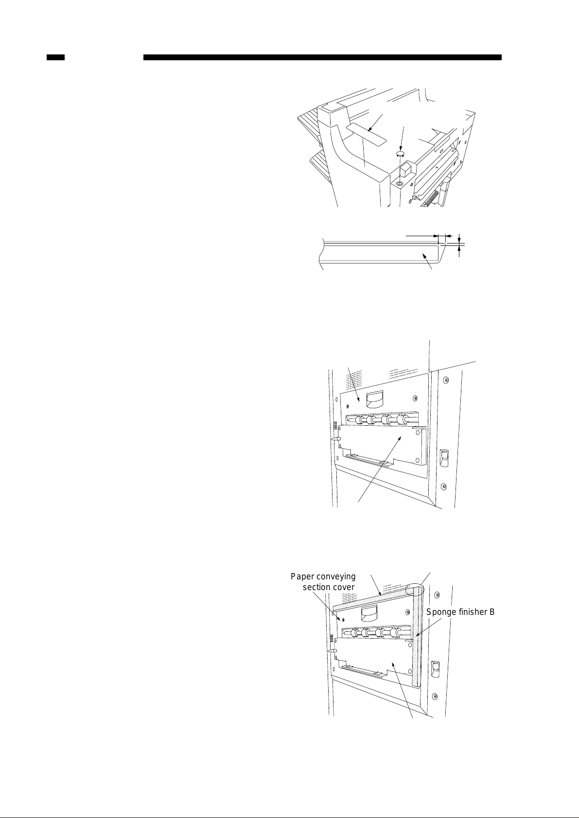
9) Insert the top cover cap into the round
hole in the finisher.
10) Peel off the indication label sheet from
its backing paper and attach the sheet
to the upper front cover of the finisher
as shown in the diagram.
1 1) Connect the signal cable for the finisher
to the connector on the copier.
Indication label sheet
Top cover cap
5 mm
3 mm
Indication label sheet
12) Peel off the separate sheet stuck to the
double faced tape of the Sponge, Finisher A. Stick Sponge, Finisher A to the
paper conveying section cover along
the edge (X, Y).
13) Peel off the separate sheet stuck to the
two double faced tape of the Sponge,
Finisher B. Stick the narrow side tape
toward Sponge, Finisher A, and the
wide side tape to along the edge of the
latch catch assembly.
*Be sure that the short edge of the
Sponge, Finisher B align with the long
edge of the Sponge, Finisher A.
Paper conveying section cover
Latch catch assembl
Sponge finisher A
Paper conveying
section cover
X
Y
*
Sponge finisher B
vi
Latch catch assembly
Page 17

Installing the relay cable and IPC PCB
For the 62 copies per minute copier
1) Remove the five screws securing the
rear cover of the copier and then the
rear cover .
2) Remove the fifteen screws securing the
main PCB cover and then the main PCB
cover.
INSTALLATION
Main PCB cover
3) Insert the board support into the round
hole in the main PCB shield.
4) Connect the 10-pin connector of the
relay cable to connector J2 on the IPC
PCB.
5) Connect connector J1 of the IPC PCB
to CN19 on the main PCB and insert
the board support into the round hole
in the IPC PCB to secure the IPC PCB
in place.
6) Pass the remaining portion of the relay
cable through the slot in the main PCB
shield.
Board support
IPC PCB
Main PCB shield
CN19
10-pin connector
J1
Board support
Slot
vii
Page 18

INSTALLATION
7) Remove the two screws securing the
main PCB shield and open the main
PCB shield forward.
8) Detach the 6-pin connector of the main
wiring.
9) Connect the detached main wiring 6pin plug and receptacle to the 6-pin
receptacle and plug of the relay cable
respectively.
Main PCB shield
Screw
6-pin connector
Screw
6-pin connector
10) Secure the wiring of the relay cable
using the two PLT1M bands.
Relay cable
PLT1M band PLT1M band
viii
Page 19

INSTALLATION
Installing the relay cable and IPC PCB
For the 42/52 copies per minute copier
1) Remove the signal cable of the DF from
the copier. Remove the seven screws
securing the rear cover , the two screws
securing the controller cover and then
the rear cover and controller cover from
the copier.
2) Remove the eight screws securing the
main PCB cover, the six screws securing the sequence cover and then the
main PCB cover and sequence cover
from the copier.
3) Insert the rocking support into the round
hole in the main PCB.
Main PCB cover
Sequence cover
Main PCB
Rocking support
4) Connect the 10-pin connector of the
relay cable to connector J2 on the IPC
PCB.
5) Connect J1 of the IPC PCB to CN15
on the main PCB and insert the rocking support into the round hole in the
IPC PCB to secure the IPC PCB in
place.
Main PCB
CN15
J1
IPC PCB
Rocking support
ix
Page 20

INSTALLATION
6) Detach the 6-pin connector extending
from CN21 on the engine output PCB.
7) Connect the detached 6-pin plug and
receptacle to the 6-pin receptacle and
plug of the relay cable respectively.
8) Secure the wiring of the relay cable
using the wire saddle.
Adjusting height and slope
1) To correct the height, loosen the fixing
screw on the front and rear casters on
the pickup side of the finisher.
2) To increase the height of the finisher,
turn the adjusting bolt in the direction
of arrow A in the following figure; turn
the adjusting bolt as needed while referring to the index on the caster . (Perform this for both front and rear casters.)
Engine output PCB
Wire saddle
6-pin connector
CN21
6-pin connector
Screws
Adjusting bolt
A
Index
3) To decrease the height of the finisher,
turn the adjusting bolt in the direction
of arrow B in the following figure; turn
the adjusting bolt as needed while referring to the index on the caster . (Perform this for both front and rear casters.)
x
Screws
Adjusting bolt
B
Index
Page 21

INSTALLATION
B
Adjusting bolt
Screws
Index
4) To correct any slope, loosen the fixing
screw on both front and rear casters on
the delivery side of the finisher.
5) To decrease the gap between the finisher and the copier, turn the adjusting
bolt in the direction of arrow A in the
following figure; turn the adjusting bolt
as needed while referring to the index
on the caster. (Perform this for both front
and rear casters.)
6) To increase the gap between the finisher and the copier, turn the adjusting
bolt in the direction of arrow B in the
following figure; turn the adjusting bolt
as needed while referring to the index
on the caster. (Perform this for both front
and rear casters.)
7) Connect the finisher to the copier, and
check to see that the difference in height
and the slope are within the indicated
tolerances; otherwise, make the adjustments once again.
8) When done, disconnect the finisher
from the copier, and tighten the fixing
screws on the casters.
Screws
Adjusting bolt
A
Index
9) To prevent loosening of the adjusting
bolts during relocation of the machine,
turn the adjusting bolts about 90° in the
direction of the arrow; be sure not to
over-tighten them, as such can lead to
displacement.
Adjusting bolt
90°
xi
Page 22

CHAPTER 1
GENERAL DESCRIPTION
I. FEATURES ................................. 1-1
II. SPECIFICATIONS.......................1-2
A. Specifications ............................1-2
B. Cross Section ............................1-7
III. Using the Machine.......................1-9
A. Removing Paper Jams from the
Finisher Unit ..............................1-9
B. Supplying the Finisher Unit with
Staples..................................... 1-10
C. Removing Staple Jams from the
Finisher Unit ............................1-12
D. Removing Paper Jams from the
Saddle Stitcher Unit.................1-13
E. Supplying the Saddle Stitcher Unit
with Staples .............................1-15
F. Removing Staple Jams from the
Saddle Stitcher ........................1-16
IV. MAINTENANCE BY THE
USER ........................................ 1-18
A. Maintenance by the User.........1-18
Page 23

CHAPTER 1 GENERAL DESCRIPTION
I. FEATURES
1. Accommodates large quantities of sheets.
●
Normally , the finisher holds a stack of sheets 147 mm in height in its two bins (smallsize paper: equivalent to 1000 sheets)/74 mm in height (large-size paper: equivalent to 500 sheets)
2. Has high paper transportation performance.
●
The finisher is capable of handling papers between 64 and 200 gm/m2.
3. Offers a job offset function.
●
The finisher has a job offset function for sorting non-stapled stacks of copies.
4. Offers four types of auto stapling.
●
The finisher offers a choice of four stapling modes (1-point stapling at rear , diagonal
stapling at front, diagonal stapling at rear, 2-point stapling).
5. Uses a buffer roller.
●
The use of a buffer roller enables the finisher to accept copies without interruption
from the copier even during stapling or offset operation.
6. Has a saddle stitch function.
●
The finisher can staple along the center of paper and fold it in two (up to 15 sheets).
1-1
Page 24

CHAPTER 1 GENERAL DESCRIPTION
II. SPECIFICATIONS
A. Specifications
1. Finisher Unit
Item
Stacking method
Stacking orientation
Stacking size
Paper weight
Bins
Modes
Stacking capacity
Description
Trays 1 and 2: by lifting tray
Face-down
Face-up
AB: A3, A4, A4R, A5, A5R, B4, B5, B5R, postcard
Inch: 279 x 432 mm (11″ x 17″), LGL, LTR, LTRR, STMT, STMTR
64 to 200 g/m
2
Trays 1 and 2
Non-sort:trays 1 and 2
Sort: trays 1 and 2
Staple: trays 1 and 2
Non staple sort
Small-size Tray 1: 147 mm high (1000 sheets)
(Note 1)
Tray 2: 147 mm high (1000 sheets)
Large-size Tray 1: 74 mm high (500 sheets)
(Note 1)
Staple sort Small-size Tray 1:
(Note 1)
Tray 2: 74 mm high (500 sheets)
110 mm high/30 sets (750 sheets)
Tray 2:
110 mm high/30 sets (750 sheets)
Large-size Tray 1: 74 mm high/30 sets (500 sheets)
(Note 1)
Tray 2: 74 mm high/30 sets (500 sheets)
(Note 2)
(Note 2)
(Note 2)
(Note 2)
Size mixing
Size mixing: 44 mm or less (300 sheets)
Stapling: 22 mm or less (150 sheets/30 sets)
Stacking mixing
Notes:
1. Approximate when computed with reference to 80 g/m
2. Alignment may not be correct if 750 or more small-size sheets are stacked.
3. The accuracy of the stack height is ± 7 mm.
Face-down/face-up
2
paper.
Table 1-201
1-2
Page 25

CHAPTER 1 GENERAL DESCRIPTION
Item
Stapling
Stapling position
Stapling capacity
Staple supply
Staples
Staple detection
Manual stapling
Stapling size
Paper detection
Control panel
Display
Dimensions
Description
By rotating cam
See Figure 1-201.
Small-size 50 sheets
Large-size 30 sheets
Special staple cartridge (5000 staples)
Special (staple-E1)
Provided
Not provided
1-point diagonal Front A3, B4, A4, A4R, B5, 279 × 432 mm
stapling (diagonal) (11″ × 17″), LGL, LTR, LTRR
Rear A3, B4, A4, B5, 279 x 432 mm (11″ × 17″), LTR
1-point Rear A4R, LTRR, LGL
2-point A3, B4, A4, B5, 279 x 432 mm (11″ × 17″), LTR
Provided
Not provided
Not provided
669 x 582 x 1013 mm (W x D x H; including saddle stitcher unit)
Equivalent of 80 g/m2 paper
Including two sheets of thick stock
(covers).
Weight
Power supply
Maximum power
consumption
Saddle finisher: 52 kg
From host machine (24 VDC)
170 W or less
Table 1-202
Reference:
The term “small-size” stands for A4, A5, A5R, B5, postcard, LTR, STMT, STMTR, while
the term “large-size” stands for A3, B4, A4R, B5R, LTRR, 279 x 432 mm (11″ x 17″),
LGL.
1-3
Page 26

CHAPTER 1 GENERAL DESCRIPTION
Stapling Positions (finisher unit)
1-point stapling (rear) 1-point stapling
Specified paper width
-
2-point stapling
1-point stapling
(diagonal; front)
Specified paper width
(diagonal; rear)
-
A3 and A4 B4 and B5 279 x 432 mm
(11'' x 17'')
and LTR
Figure 1-201
1-4
Page 27

2. Saddle Stitcher Unit
CHAPTER 1 GENERAL DESCRIPTION
Item
Stapling method
Folding position
Paper size
Capacity
Paper weight
Stacking capacity
Stapling
Folding
Description
Center binding (double folding)
See Figure 1-202.
A3, B4, A4R, 297mm x 432mm (11″ x 17″), LTRR
W/binding: 1 sheet
W/out binding:2 to 15 sheets
64 to 80 g/m2 (cover page up to 200 g/m2)
(including single cover page)
(Note 1)
10 sets (stack of 11 to 15 sheets), 15 sets (stack of 6 to 10 sheets),
25 sets (stack of 5 sheets or less)
Stapling position
2 points (center distribution; fixed interval)
Staple accommodation 2000 staples
Staple supply Special cartridge
Staples Special staples (Staple-D1)
Staple detection Provided
Manual stapling Not provided
Folding method Roller contact
Folding mode Double folding
Folding position Paper center
Position adjustment Provided
Power supply
From finisher unit
(24 V line x 2)
Power consumption
160 W or less
Note1: Special paper, postcards, transparencies, reproducibles, label paper and holepunched paper cannot be handled.
Table 1-203
1-5
Page 28

CHAPTER 1 GENERAL DESCRIPTION
Staple and Folding Position (saddle finisher unit)
A3
Center
of staple
210±1.0mm
88.5±2.0mm
208.5±2.0mm
Stack front edge
279mm x 432mm
(11'' x 17'')
Staple position
Center of
staple
B4
182±1.0mm
LTRR
68.5±2.0mm
188.5±2.0mm
A4R
148.5±1.0mm
45±2.0mm
165±2.0mm
216±1.0mm
79.7±2.0mm
199.7±2.0mm
139.7±1.0mm
48±2.0mm
168±2.0mm
Figure 1-202
1-6
Page 29

B. Cross Section
1. Finisher Unit
CHAPTER 1 GENERAL DESCRIPTION
[1] [2] [3] [4] [5] [6] [8]
[7] [10]
[9]
[11]
[1] Tray 1/2
[2] Shutter
[3] Delivery roller
[4] Swing guide
[5] Feed roller 2
[6] Height sensor
[7] Wrap flapper
[8] Buffer roller
[9] Buffer inlet flapper
[17] [16] [15] [14] [13] [12]
[10] Saddle stitcher flapper
[11] Inlet feed roller
[12] Feed roller 1
[13] Vertical path
[14] Stapler
[15] Knurled belt
[16] Tray lift motor
[17] Saddle stitcher unit
Figure 1-204
1-7
Page 30

CHAPTER 1 GENERAL DESCRIPTION
2. Saddle Stitcher Unit
[6]
[5]
[4]
[3]
[2]
[1]
[7]
[8]
[9]
[10]
[11]
[12]
[1] Guide plate
[2] Paper folding roller
[3] Delivery guide plate
[4] Holding roller
[5] Stitcher (front, rear)
[6] Inlet roller
[7] No.1 flapper
[8] No. 2 flapper
[9] Stitcher mount
[10] Butting plate
[11] Crescent roller
[12] Paper positioning plate
Figure 1-205
1-8
Page 31

CHAPTER 1 GENERAL DESCRIPTION
III. Using the Machine
A. Removing Paper Jams
from the Finisher Unit
If the host machine indicates the finisher paper jam message, perform the following to remove the jam.
Note, however, that paper jams at the
paper feed inlet on the finisher unit can be
removed by opening the front cover of the
host machine as the Finisher is fixed to host
machine.
1) Holding the finisher unit as shown,
move it to detach it from the host ma-
chine.
3) Open the upper cover, and check the
inside of the finisher.
Figure 1-303
4) Lift the buffer roller cover , and remove
the jam.
Figure 1-301
2) Remove any jam visible from the outside.
Figure 1-302
Figure 1-304
5) Lift the buffer roller, and remove the
jam.
Figure 1-305
1-9
Page 32

CHAPTER 1 GENERAL DESCRIPTION
6) Return the buffer roller and the buffer
roller cover to their original positions,
and close the upper cover .
Figure 1-306
7) Connect the finisher to the host machine.
B. Supplying the Finisher
If the host machine indicates the finisher unit staple supply message, perform
the following to supply it with staples.
1) Open the front cover.
Figure 1-308
2) Shift down the green lever.
Figure 1-307
8) Operate as instructed on the display.
Figure 1-309
3) When the staple cartridge has slightly
slid out, hold and pull it out.
Figure 1-310
1-10
Page 33

CHAPTER 1 GENERAL DESCRIPTION
4) Hold the empty staple case on its sides,
and slide it out.
Figure 1-311
5) Set a new staple case.
6) Pull the length of tape (used to hold
the staples in place) straight out.
Figure 1-313
7) Push in the stapler unit until the green
lever returns to its original position.
Figure 1-312
Reference:
You may set no more than one staple
cartridge at a time.
Make sure that the new cartridge is one
specifically designed for the finisher unit.
Figure 1-314
8) Check to make sure that the stapler has
been locked in place, and close the
front cover.
Figure 1-315
1-11
Page 34

CHAPTER 1 GENERAL DESCRIPTION
C. Removing Staple Jams
from the Finisher Unit
If the host machine indicates the finisher unit staple jam message, perform the
following to remove the jam.
1) Remove the stack waiting to be stapled
from the delivery tray.
Figure 1-316
4) When the staple cartridge has slightly
slid out, hold and pull it out.
Figure 1-319
5) Shift down the tab on the staple cartridge.
2) Open the front cover.
Figure 1-317
3) Shift down the green lever.
Figure 1-320
6) Remove all staples that have slid out
of the staple case.
Figure 1-321
1-12
Figure 1-318
Page 35

CHAPTER 1 GENERAL DESCRIPTION
7) Return the tab on the staple cartridge
to its original position.
8) Return the staple cartridge to its original position, and close the front cover .
Figure 1-322
Reference
When the cover has been closed, the
stapler unit will automatically execute idle
punching several times to advance the
staples.
D. Removing Paper Jams
from the Saddle Stitcher
Unit
If the host machine indicates the saddle
stitcher unit paper jam message, perform
the following to remove the jam.
1) Holding the saddle stitcher unit as
shown, move it to detach it from the
host machine.
Figure 1-323
2) Open the front lower cover.
Figure 1-324
1-13
Page 36

CHAPTER 1 GENERAL DESCRIPTION
3) Turn the knob on the right side.
Figure 1-325
4) Turn the knob on the left side while
pushing it in.
6) Open the inlet cover, and remove the
jam.
Figure 1-328
7) Close the front lower cover.
Figure 1-326
5) Remove the jam.
Figure 1-327
Figure 1-329
8) Connect the finisher unit.
9) Operate as instructed on the display.
1-14
Page 37

CHAPTER 1 GENERAL DESCRIPTION
E. Supplying the Saddle
Stitcher Unit with Staples
If the host machine indicates the saddle
stitcher unit staple supply message, perform the following to supply it with staples.
1) Open the front lower cover.
Figure 1-330
3) Pull the stitcher unit to the front once,
and then shift it up.
Figure 1-332
4) Hold the empty cartridge on its sides,
and remove it.
2) Slide out the stitcher unit.
Figure 1-331
Figure 1-333
5) Fit the new cartridge.
Figure 1-334
Reference
You must always replace both cartridges
at the same time.
1-15
Page 38

CHAPTER 1 GENERAL DESCRIPTION
6) Pull the stitcher to the front once, and
then return it to its original position.
Figure 1-335
7) Push in the stitcher unit, and close the
front cover.
F. Removing Staple Jams
from the Saddle Stitcher
If the host machine indicates the saddle
stitcher unit staple jam message, perform
the following to remove the jam.
1) Open the front lower cover.
Figure 1-337
Figure 1-336
2) Slide out the stitcher unit.
Figure 1-338
3) Pull the stapler of the stitcher unit to
the front once, and then shift it up.
1-16
Figure 1-339
Page 39

CHAPTER 1 GENERAL DESCRIPTION
4) Hold the cartridge on its sides, and remove it.
Figure 1-340
5) Push down on the area identified as A,
and pull up the tab identified as B.
7) Return the cartridge to its original position.
Figure 1-343
8) Pull the stitcher of the stitcher unit to
the front once, and then return it to its
original position.
Figure 1-341
6) Remove the staple jam, and return the
tab B to its original position.
Figure 1-342
Figure 1-344
9) Push the stitcher unit back to its original position, and close the front lower
cover.
Figure 1-345
Reference
Whenever you have removed a staple
jam, be sure to execute staple edging.
1-17
Page 40

CHAPTER 1 GENERAL DESCRIPTION
IV. MAINTENANCE BY THE USER
A. Maintenance by the User
As of May 2000
No.
1
2
Item
Replacing the staple cartridge (finisher unit)
Replacing the staple cartridge (saddle
stitcher unit)
When the apropriate indication is made
on the copier’s display.
Timing
Caution:
The finisher unit and the saddle stitcher unit use different cartridge types. Be sure
that the appropriate type is used for each.
Table 1-401
1-18
Page 41

CHAPTER 2
FINISHER UNIT BASIC OPERATION
1. This chapter discusses the purpose and role of each of the finisherís functions, and
the principles of operation used for the finisher mechanical and electrical systems. It
also explains the timing at which these systems are operated.The symbol in drawings indicates transmission of mechanical drive, and signals marked by together
with the signal name indicates the flow of electrical signals.
2. In descriptions of digital circuits on the finisher, “1” indicates a high signal voltage level,
while “0” indicates a low signal voltage level. Voltage values dif fer according to circuit.
A microprocessor is used on the finisher. A description of microprocessor operation is
omitted in this chapter as it is practically impossible to check internal operation of the
microprocessor.
Descriptions in this chapter also assume that PCBs will not be repaired at user sites.
For this reason, descriptions of circuits on PCBs is limited to block diagrams. Two
types of block diagrams are provided for separate functions: diagrams indicating details from sensors up to input sections of major PCBs, and diagrams indicating details
from the output sections of major PCBs up the loads.
I. BASIC OPERATION..................2-1
A. Outline ................................. 2-1
B. Outline of Electrical
Circuitry................................2-2
C. Inputs to and Outputs from the
Finisher Controller PCB....... 2-4
II. FEED/DRIVE SYSTEM ...........2-10
A. Outline ............................... 2-10
B. Type of Delivery Paths....... 2-15
C. Feeding and Delivering...... 2-18
D. Job Offset .......................... 2-21
E. Staple Operation................ 2-24
F. Stapler Unit........................2-32
G. Tray Operation...................2-38
H. Detecting the Height of
Stack on the Tray...............2-40
I. Shutter Operation .............. 2-42
J. Buffer Path Operation ........2-46
K. Detecting Jams ..................2-49
III. POWER SUPPLY SYSTEM .... 2-54
Page 42

I. BASIC OPERATION
A. Outline
CHAPTER 2 FINISHER UNIT BASIC OPERATION
It is designed to deliver copies arriving from its host copier, and its modes of delivery
include simple stacking, job offset
(Note)
, and staple.
All operations involved in these modes are controlled by the finisher controller PCB,
according to the appropriate commands from the host machine.
And copies from the host machine may be routed to the saddle stitcher unit.
Swing guide drive system
Alignment drive system
Stapler drive system
Delivery drive system
Control system
Feeder drive system
Shutter drive system
Tray drive system
Saddle stitcher unit control system
Figure 2-101
Note:
The term job offset refers to shifting each sorting job, separating a single
stack into several stacks.
2-1
Page 43

CHAPTER 2 FINISHER UNIT BASIC OPERATION
B. Outline of Electrical Circuitry
The finisher’s sequence of operation is controlled by the finisher controller PCB. The
finisher controller PCB is a 16-bit microprocessor (CPU), and is used for communication
with the host machine (serial) in addition to controlling the finisher’s sequence of operations.
The finisher controller PCB responds to the various commands coming from the host
machine through a serial communications line to drive solenoids, motors, and other loads.
In addition, it communicates the finisher’s various states (information on sensors and
switches) to the host machine through a serial communications circuit.
The finisher controller PCB not only communicates with the saddle stitcher controller
PCB but also communicates the saddle stitcher unit’s various states (information on sensors and switches) to the host machine.
The ICs used on the finisher controller PCB are designed for the following:
●
Q1 (CPU)
Controls sequence of operations.
●
Q2 (EP-ROM)
Backs up adjustment values.
●
Q7
Contains sequence programs.
●
Q8/Q89 (RAM)
Backs up initial setting data.
●
Q4 (communications IC)
Communicates with the host machine and the saddle stitcher unit.
●
Q14 (regulator IC)
Generates 5V.
Figure 2-102 shows the flow of signals between the finisher and the options controller.
2-2
Page 44

CHAPTER 2 FINISHER UNIT BASIC OPERATION
Saddle stitcher
controller PCB
Host machine
(DC controller PCB CPU)
Finisher controller
PCB communication
Q1
CPU
Q2
EEP-ROM
Q4
IC
Q7
EP-ROM
Q8/Q89
RAM
Q14
Regulator IC
Figure 2-102
Motor
Solenoid
Switch
Sensor
2-3
Page 45

CHAPTER 2 FINISHER UNIT BASIC OPERATION
C. Inputs to and Outputs from the Finisher Controller PCB
1. Inputs to the Finisher Controller PCB
Finisher controller PCB
Inlet sensor
Delivery sensor
Stapling tray
sensor
Shutter open
sensor
Alignment plate
home position
sensor
Stapler shift home
position sensor
PI1
PI3
PI4
PI5
PI6
PI7
J106-1
-3
-2
J134-1
-2
-3
J122-3
-1
-2
J118-3
-1
-2
J121-3
-1
-2
J129-3
-1
-2
-9
-7
-8
-3
-2
-1
-1
-3
-2
-1
-3
-2
-4
-6
-5
-1
-3
-2
-3
-1
-2
J202
-5
-6
-7
J208
-11
-9
-10
J207A
-3
-1
-2
J205
-8
-6
-7
J207A
-3
-1
-2
J210
J17-7
-9
-8
J11-3
-2
-1
J9A-1
-3
-2
J12B-4
-6
-5
J9A-4
-6
-5
J12A-7
-9
-8
+5V
PENT
+5V
PDEL
+5V
STPTY
+5V
STOPN
+5V
JOGHP
+5V
STPHP
When the sensor detects
paper, “1”.
When the sensor detects
paper, “1”.
When the sensor detects
paper, “1”.
When the shutter opens, “1”.
When the alignment plate
is at the home position, “1”.
When the stapler is at the
home position, “1”.
Tray home
position sensor
2-4
PI8
J130-3
-1
-2
Figure 2-103
J12A-4
-6
-5
+5V
TRYHP
When the tray is at the
home position, “1”.
Page 46

CHAPTER 2 FINISHER UNIT BASIC OPERATION
2. Inputs to the Finisher Controller PCB
PI10
Delivery motor
clock sensor
J120-1
-2
-3
-9
-8
-7
-3
-4
-5
J207A
J9A-9
-8
-7
Finisher controller PCB
+5V
DELCLK
While the delivery motor
is rotating, alternately
between “0” and “1”.
Tray 1 paper
sensor
Tray 2 paper
sensor
Buffer path paper
sensor
Joint sensor
Door open
sensor
Buffer path inlet
paper sensor
PI11
PI12
PI14
PI15
PI16
PI17
J101-3
-1
-2
J102-3
-1
-2
J110-3
-1
-2
J117-3
-1
-2
J113-3
-1
-2
J105-3
-1
-2
-1
-3
-2
-1
-3
-2
-3
-1
-2
J1010
-3
-1
-2
J1020
-1
-3
-2
-4
-6
-5
J201
J201
-6
-4
-5
-3
-1
-2
J14-1
J14-4
J24-4
J12A-1
J12B-1
J24-1
+5V
-3
FSTTRAY*
-2
+5V
-6
SNDTRAY*
-5
+5V
-6
BUFPASS
-5
+5V
-3
JOINT
-2
+5V
-3
DROPN
-2
+5V
-3
BUFENTR
-2
When paper is present
on tray 1, “0”.
When paper is present
on tray 2, “0”.
When paper is in the
buffer path, “1”.
When the finisher is
joined with the copier, “1”.
When the front door is
open, “0”.
When paper is present at
the buffer path inlet, “1”.
Swing guide
open sensor
Tray lift motor
clock sensor 1
Tray lift motor
clock sensor 2
PI18
J127-3
PI9
PI19
Sensor PCB
-1
-2
J400-3
-1
-2
J400-6
-4
-5
-1
-3
-2
J204
-3
-1
-2
Figure 2-104
J11-8
-10
J14-10
-12
-11
J14-7
+5V
SWGOPN
-9
+5V
SFTCLK1
+5V
-9
SFTCLK2
-8
When the swing guide is
open, “1”.
When the tray lift motor
is rotating, alternately
between “1” and “0”.
When the tray lift motor
is rotating, alternately
between “1” and “0”.
2-5
Page 47

CHAPTER 2 FINISHER UNIT BASIC OPERATION
3. Inputs to the Finisher Controller PCB
PI20
PS1
J125-1
-2
-3
J114-3
-4
-2
Swing motor
clock sensor
Height sensor
Door switch
N. O.
MS1
Swing guide closed detecting switch 1
N. O.
MS2
-5
-4
-3
-7
-8
-9
J207B
-1
-2
J112
-1
-2
J209
J9B-5
J6-2
J5-1
J5-9
-10
Finisher controller PCB
+5V
-4
SWGCLK
-3
When the swing motor is
rotating, alternately between
“0” and “1”.
-1
-3
-4-1
-3
+5V
V0
Vin
Measures the distance between
the sensor and the top of the
stack on the tray.
+24V
+24VMOVE
DRSW
When the front door
and the upper cover
are closed, “1”.
Swing guide closed detecting switch 2
N. O.
MS6
Safety zone switch
J131-3
MS3
N. C.
N. O.
C.
-2
-1
Shutter closed detecting switch
N. C.
N. O.
C.
MS4
Tray upper limit detecting switch
N. C.
MS5
J209
J206
J132
-3
-4
-3
-2
-1
-1
-2
J5-11
-12
J5-4
J7-3
J5-7
-5
-6
-2
-1
-8
+24VSTPL
+24VSHIFT
TRAYSAF
SHUTCLD
+24VSHIFT
TRYLMT
SWGGCLD
When the swing
guide is closed,
“1”.
When the tray is at
the delivery slot, “1”.
When the shutter is
closed, “1”.
When the tray is at
the upper limit, “0”.
2-6
Figure 2-105
Page 48

CHAPTER 2 FINISHER UNIT BASIC OPERATION
4. Inputs to and Outputs from the Finisher Controller PCB
Staple edging
sensor
Staple home
position sensor
Cartridge switch
Staple switch
Stapler unit
Finisher controller PCB
When a staple is at the edge of
*
the stapler, “0”.
When the stapler is at the home
*
position, “0”.
*
When a cartridge is present, “0”.
When staples are present in
*
the cartridge, “0”.
*
When the stapler is connected,
“0”.
Saddle stitcher
controller PCB
Host machine
J131-8 J400-1
-7
-6
-5
-4
-3
-2
-3
-4
-5
-6
J500-1
-2
Communication line
J2-1
Communication line
Figure 2-106
2-7
Page 49

CHAPTER 2 FINISHER UNIT BASIC OPERATION
5. Outputs from the Finisher Controller PCB
Finisher controller PCB
Flapper solenoid
SL1
Buffer inlet solenoid
SL2
Buffer outlet solenoid
SL3
Paddle solenoid
SL5
Escape solenoid
SL6
-1 -2
-2
-1 -3
-2
-1 -2
-2
-1 -2
-2
-1 -3
-2
J107
J108
J109
J128
J123
-1 -11
-2 -10
J207B
-10 -2
-11 -1
J207A
J12A-10
-11-1
J12B-9
-10-2
J24-7
-8-1
J9B-1
-2-1
J9A-10
-11-2
+24V
When "0", the solenoid turns on.
FLPSL*
+24V
When "0", the solenoid turns on.
ENTSL*
+24V
When "0", the solenoid turns on.
EXITSL*
+24V
When "0", the solenoid turns on.
PDLSL*
+24V
When "0", the solenoid turns on.
ESCPSL*
Belt escape solenoid
SL7
First feed motor
M1
2-8
-1 -2
-2
J500
-1
J12B-7
J10-1
Figure 2-107
-8
BESCPSL*
-2
-3
B*
-4
A*
-5
B
-6
A
+24V
When "0", the solenoid turns on.
+24V
According to rotation direction/speed,
changes between + and - in sequence.
Page 50

CHAPTER 2 FINISHER UNIT BASIC OPERATION
6. Outputs from the Finisher Controller PCB
Delivery motor
Alignment motor
Stapler shift motor
Finisher controller PCB
According to rotation
direction/speed, changes
between + and -.
According to rotation
direction/speed, changes
between + and - in sequence.
According to rotation
direction/speed, changes
between + and - in sequence.
Staple motor
Tray lift motor
Swing motor
Second feed motor
According to rotation
direction/speed, changes
between + and -.
According to rotation
direction/speed, changes
between + and -.
According to rotation
direction/speed, changes
between + and -.
According to rotation
direction/speed, changes
between + and -.
Inlet feed motor
According to rotation
direction/speed, changes
between + and - in sequence.
Figure 2-108
2-9
Page 51

CHAPTER 2 FINISHER UNIT BASIC OPERATION
II. FEED/DRIVE SYSTEM
A. Outline
The finisher is designed to operate according to the commands from its host machine
to deliver arriving copies to trays in the appropriate mode: simple stacking, job offset,
stapling.
See Figure 2-201 for a diagram of the four modes of delivery.
Method of delivery
Normal delivery tray
Normal
delivery
Saddle stitch delivery
Figure 2-201
Simple stacking
Job offset
Staple
Front diagonal
Rear 1-point
Rear diagonal
2-point
2-10
Normal delivery tray
To saddle stitcher unit
Figure 2-202
Page 52

CHAPTER 2 FINISHER UNIT BASIC OPERATION
1. Normal Delivery
a. Simple Stacking
The finisher delivers copies directly to the tray.
Tray Tray
CopiesCopies
Delivery roller
Figure 2-203
Feed roller 1
Feed roller 2
2-11
Page 53

CHAPTER 2 FINISHER UNIT BASIC OPERATION
b. Job Offset
The finisher forwards all copies of each sort job to the stapling tray . The first sort job on
the stapling tray is delivered with a shift to the front of about 30 mm, and the second sort
job is delivered without being shifted. Whether the first copy or the last copy of a sort job
should be shifted is determined by the host machine.
Tray
Each sort job is stacked
alternately.
Figure 2-204
Swing guide
Stapling tray
Results of Delivering 4 Sets
Direction of delivery
Stopper
Delivery roller
Figure 2-205
Figure 2-206
Feed roller 1
Copies handled
by job offset
2-12
Page 54

CHAPTER 2 FINISHER UNIT BASIC OPERATION
c. Stapling
The finisher stacks copies arriving from its host machine on the stapling tray. Then, it
staples and delivers the copies to the appropriate tray.
Tray
Copies
Staple
Swing guide
Delivery roller
Front diagonal stapling
Rear diagonal stapling
Stapling
tray
Stopper
Figure 2-207
Rear 1-point stapling
Feed roller 2
Paper width/2
2-point stapling
Figure 2-208
2-13
Page 55

CHAPTER 2 FINISHER UNIT BASIC OPERATION
2. Saddle Stitch Delivery
A copy arriving in the finisher from the host machine is routed to the saddle stitcher by
the paper deflecting plate. The saddle stitcher executes stitching and saddling operations
on the copy and then delivers it to the saddle stitcher tray.
For discussions of stacks in the saddle stitcher, see Chapter 3.
To saddle stitcher
Figure 2-209
2-14
Page 56

CHAPTER 2 FINISHER UNIT BASIC OPERATION
B. Type of Delivery Paths
The finisher has three different paper paths for delivery, each selected to suit paper
size and delivery mode.
1. Straight Path
When stacking copies shown in Table 2-201, the copies pass under the buffer roller.
Copy size Length or width 182 mm or less
Typical copy examples A5, A5R, STMT, STMTR, postcard, thick stock
Table 2-201
Delivery roller
Buffer roller
Figure 2-210
2. Buffer Paper Path 1
When stacking copies shown in Table 2-202, the copies pass over the buffer roller,
increasing the distance between copies.
Copy size Length and width 182 mm or more
Typical copy examples A3, B4, A4, A4R, B5, B5R, 279mm × 432mm (11″ × 17″), LGL, LTR,
LTRR, transparencies (excluding thick stock)
Table 2-202
Buffer roller
Delivery roller
Figure 2-211
Feed roller 2
2-15
Page 57

CHAPTER 2 FINISHER UNIT BASIC OPERATION
3. Buffer Paper Path 2
This is the paper path when copy sizes shown in Table 2-203 are stacked. A maximum
of two copies (two originals or more in the staple mode) are wrapped round the buffer
roller, during which job offset and stapling are performed on the stapling tray.
Copy size Length 182 to 232mm, and width 182 to 297mm
Typical copy examples A4, B5, LTR, (excluding transparencies and thick stock)
T able 2-203
The following shows paper delivery operation in the case of two originals in the staple
mode.
1) The first copy is moved in the direction of the buffer roller.
Buffer roller
1st copy
Figure 2-212
2) The first copy wraps around the buffer roller and, at the same time, the second copy
arrives from the host machine.
1st copy
2nd copy
Figure 2-213
2-16
Page 58

CHAPTER 2 FINISHER UNIT BASIC OPERATION
3) The second copy is laid over the first copy.
1st copy
2nd copy
Figure 2-214
4) The first and second copies are simultaneously pulled into the stapling tray.
2nd copy
1st copy
Figure 2-215
Cauiton:
The second copy as explained here is moved through buffer paper path 1. This fact is omitted
from the discussion to avoid interrupting the sequence of operations.
2-17
Page 59

CHAPTER 2 FINISHER UNIT BASIC OPERATION
C. Feeding and Delivering
1. Outline
The finisher moves copies arriving from the host machine to the delivery tray , stapling
tray , or the saddle stitcher unit according to the mode of delivery. On the stapling tray, the
copies are subjected to job offset or stapling as instructed by the host machine.
The first feed motor (M1), second feed motor (M8) and inlet feed motor (M9) are stepping motors, and delivery motor (M2) is a DC motor. These motors are controlled by the
microprocessor (CPU) on the finisher controller PCB, and rotate either clockwise or counterclockwise.
The paper paths are equipped with the following four sensors for detection of paper
(arrival, passage):
●
Inlet sensor (PI1)
●
Delivery sensor (PI3)
●
Stapling tray sensor (PI4)
●
Buffer path paper sensor (PI14)
In addition, each delivery tray is equipped with a sensor designed to detect the presence/absence of paper on it.
●
No.1 tray paper sensor (PI11)
●
No.2 tray paper sensor (PI12)
If a copy fails to reach or move past each sensor within a specific period of time, the
finisher controller PCB identifies the condition as a jam, and stops the ongoing operation
and at the same time informs the host machine of the condition. When all doors are closed
after the paper jam is removed, the buffer path inlet paper sensor (PI17) checks whether
or not copies are being detected in addition to the above four sensors (inlet sensor , delivery sensor, stapling tray sensor and buffer path paper sensor). If the sensors detect a
copy, the finisher unit judges that paper jams have not completely been removed, and
sends the paper jam removal signal to the host machine again.
2-18
Page 60

PI10
PI20
Escape solenoid drive signal ESCPSL
Alignment motor drive signal
Delivery motor drive signal
Delivery motor clock signal DELCLK
Swing motor drive signal
Swing motor clock signal SWGCLK
Shift motor clock detection signal 1 SFTCLK1
2-19
Figure 2-216
SL6
M4
M3
M6
SL7
M2
SL1
SL2
M7
SL3
SL5
PI9
Shift motor clock detection signal 2 SFTCLK2
PI19
M5
Tray lift motor drive signal
Paddle solenoid drive signal PDLSL
Second feed motor drive signal
M1M8 M9
First feed motor drive signal
Inlet feed motor drive signal
Buffer outlet solenoid drive signal EXITSL
Buffer inlet solenoid drive signal EXTSL
Flapper solenoid drive signal FLPSL
Belt escape solenoid drive signal BESCPSL
Stapler motor drive signal
Stapler shift motor drive signal
Finisher controller PCB
CHAPTER 2 FINISHER UNIT BASIC OPERATION
Page 61

2-20
CHAPTER 2 FINISHER UNIT BASIC OPERATION
No. 2 tray paper detection signal SNDTRAY
No. 1 tray paper detection signal FSTTRAY
Figure 2-217
PI12
PI4
PI1
PI11
Stapling tray paper detection signal STPTY
Buffer path paper
detection signal BUFPASS
PI3
Delivery detection signal PDEL
PI14
PI17
Buffer path inlet paper
detection signal BUFENTR
Inlet paper detection signal PENT
Finisher controller PCB
Page 62

CHAPTER 2 FINISHER UNIT BASIC OPERATION
D. Job Offset
1. Outline
In the job offset mode, sort jobs and entire copy groups are shifted to the front for
delivery to the tray, and other copies are delivered to the tray without a shift.
The copies are shifted by the alignment plate. The alignment plate is checked by the
alignment home position sensor (PI6) to find out whether it is at the home position.
The finisher controller PCB drives the alignment plate motor (M3) at power-on to re-
turn the alignment plate to its home position.
The finisher controller PCB stops the delivery motor (M2) when the trailing edge of the
copy has moved past the feed roller 2. Then, the finisher controller PCB rotates the delivery motor counterclockwise, and drives the swing motor (M7). As a result, the drive of the
delivery motor is transmitted to the swing guide to move up the guide. When the swing
guide open detection sensor (PI18) detects the swing guide, the delivery motor stops, and
the swing guide is held at the up position.
When the swing guide has moved up, the feed belts attached to the feed roller 2 move
the copy to the stapling tray. The presence of paper on the stapling tray is monitored by
the stapling tray paper sensor (PI4). (The first sheet is fed to the stapling tray while the
swing guide is moving up.)
The finisher controller PCB drives the alignment motor (M3) in advance, and keeps
the alignment plate in wait at a point 10 mm behind the trailing edge of a sheet. Whenever
one sheet is moved to the stapling tray, each sheet is aligned, and when the fifth or last
sheet in a sort job/group is fed to the stapling tray , the guide plate retaining solenoid (SL6)
moves the guide plate away and under the stapling tray. From then on, the alignment
motor shifts the sheets to the front by 30 mm.
When the copy has been shifted, the finisher controller PCB rotates the alignment
motor counterclockwise to move the alignment plate to a point 10 mm behind the trailing
edge of the sheet. This alignment operation is repeated until alignment of the fifth or last
sheet in a sort job is completed. At this time, the swing guide is moved down and is closed,
and the delivery motor rotates clockwise to deliver the sheet.
2-21
Page 63

CHAPTER 2 FINISHER UNIT BASIC OPERATION
Guide plate
Paper
Alignment plate
Alignment plate
home position sensor (PI6)
Alignment motor (M3)
Escape solenoid
(SL6)
Sequence of Operation (job offset)
Inlet sensor (PI1)
Delivery sensor (PI3)
Inlet feed motor (M9)
First feed motor (M1)
Second feed
motor (M8)
Delivery motor (M2)
Stapling tray
sensor (PI4)
Alignment motor (M3)
Alignment guide home
position sensor (PI6)
Swing guide (M7)
Swing guide closed
sensor (PI18)
Swing guide closed
detect switch 1 (MS2)
Escape solenoid (SL6)
Figure 2-218
Start signal
Host machine delivery signal
2-22
: Motor CW rotation : Motor CCW rotation
Figure 2-219
Page 64

CHAPTER 2 FINISHER UNIT BASIC OPERATION
2. Flow of Job Offset Operations
1) The swing guide moves up and, at the same time, the feed belts move the sheet to the
stapling tray.
Swing guide
Offset sheet
Feed roller 2
Feed belts
Tray 1/2
Delivery
roller
Stapling tray
Stopper
Figure 2-220
2) The alignment plate shifts the sheet to the front.
Existing stack
Alignment plate
Offset sheet
Figure 2-221
3) The swing guide moves down and, at the same time, the delivery roller delivers the
sheet.
Offset sheet
Swing guide
Tray 1/2
Delivery
roller
Stapling tray
Figure 2-222
Feed roller 2
Feed belts
Stopper
2-23
Page 65

CHAPTER 2 FINISHER UNIT BASIC OPERATION
E. Staple Operation
1. Outline
The stapler unit staples a stack of as many sheets as specified.
The stapling position differs according to the selected staple mode and paper size.
The stapler unit is checked by the stapler shift home position sensor (PI7) to find out
whether it is at the home position.
When starting operation after power-on, the finisher controller PCB drives the stapler
shift motor (M4) to return the stapler unit to the home position. If the stapler is already at
the home position, it is kept as it is in wait.
Stapler shift
motor (M4)
Sheets
Stapler shift home
position sensor (PI7)
Stapler
Figure 2-223
2-24
Page 66

CHAPTER 2 FINISHER UNIT BASIC OPERATION
Paper width/2
Front diagonal stapling
Rear diagonal stapling
2-point stapling
Rear 1-point stapling
Figure 2-224
2-25
Page 67

CHAPTER 2 FINISHER UNIT BASIC OPERATION
2. First Sheet
The finisher controller PCB stops the delivery motor (M2) as soon as the trailing edge
of the first sheet has moved past the feed roller 2. Then, it rotates the delivery motor
clockwise to switch the gear drive to the swing motor (M7), causing the swing guide to
move up. When the swing guide open sensor (PI18) finds the swing guide at the up position, the swing motor stops, maintaining the swing guide at the up position.
When the swing guide has moved up, the feed belts of the feed roller 2 move the sheet
to the stapling tray. (The first sheet is fed to the stapling tray while the swing guide is
moving up.) The presence of paper on the stapling tray is detected by the stapling tray
paper sensor (PI4).
The finisher controller PCB drives the alignment plate shift motor (M3) when the stapling tray paper sensor has detected paper to put sheets in order. The alignment plate is
kept in wait in advance at a point 10 mm behind the trailing edge of the paper.
The swing guide is kept in wait at the up position until the last sheet is output onto the
stapling tray.
Swing guide
1st sheet
Tray 1/2
Feed roller 2
Feed belts
Delivery roller
Stapling tray
Stapler
Figure 2-225
2-26
Page 68

Swing guide
y
)
Swing guide open
sensor (PI18)
CHAPTER 2 FINISHER UNIT BASIC OPERATION
Swing guide closed
detecting switches
(MS2/MS6)
Swing motor (M7)
Figure 2-226
Deliver
Delivery roller
Swing motor
clock sensor
(PI20)
Delivery motor
clock sensor
(PI10)
motor (M2
2-27
Page 69

CHAPTER 2 FINISHER UNIT BASIC OPERATION
3. 2nd and Subsequent Sheets
The finisher controller PCB turns on the belt escape solenoid (SL7) before the trailing
edge of the second and subsequent sheets have moved past the feed roller 2 to make the
feed belt escape. This operation is performed to reduce the time it takes for the trailing
edge of the paper to fall on the stapling tray , and to improve the product duty. The finisher
controller PCB turns on the paddle solenoid (SL5) as soon as the trailing edge of the
second and subsequent sheets have moved past the feed roller 2, causing the drive of the
second feed motor (M8) to rotate the paddle. The sheets are pushed by the paddle and
moved to the stapling tray . Almost simultaneously with the trailing edge of the sheet falling
into the stapling tray , the belt escape solenoid turns off to return the feed belts that were in
the escape position to its original position, and feed the sheet onto the stapling tray . When
the sheet has been output onto the stapling tray, the finisher controller PCB rotates the
alignment motor (M3) to put the sheets in order.
Swing guide
2nd and
subsequent
sheets
Paddles
Tray 1/2
Delivery
roller
Stapling tray
Figure 2-227
Feed roller 2
Feed belts
SL7
Belt escape solenoid
Stapler
2-28
Page 70

Feed belts
CHAPTER 2 FINISHER UNIT BASIC OPERATION
Escape direction
Belt escape
solenoid (SL7)
Figure 2-228
Paddles
Paddle
solenoid (SL5)
Paddles
2nd and
subsequent sheets
1st sheet
Stapler
M8
2nd feed motor
Stopper
Figure 2-229
2-29
Page 71

CHAPTER 2 FINISHER UNIT BASIC OPERATION
4. Last Sheet
When the last sheet has been put in order, the finisher controller PCB turns on the
alignment motor (M3) to move the alignment plate to the alignment position (to butt the
plate against the stack). Then, the finisher controller PCB rotates the swing motor (M7)
counterclockwise to move down the swing guide.
The finisher controller PCB moves the stapler according to the staple mode for stapling.
From then on, it rotates the delivery motor (M2) clockwise to delivery the stack to the
tray.
Swing guide
Sheets
Feed roller 2
Feed belts
Tray 1/2
Delivery
roller
Stapling tray
Stapler
Figure 2-230
2-30
Page 72

Swing guide
CHAPTER 2 FINISHER UNIT BASIC OPERATION
Delivery roller
Swing motor (M7)
Delivery motor (M2)
Figure 2-231
2-31
Page 73

CHAPTER 2 FINISHER UNIT BASIC OPERATION
F. Stapler Unit
Stapling is executed by the stapler motor (M6). A single rotation of the cam by the
motor results in one stapling operation.
The cam is checked by the stapling home position sensor (PI22) to find out whether it
is at the home position.
The stapler motor is controlled by the microprocessor (Q1) on the finisher controller so
that it is rotated clockwise or counterclockwise.
When the stapling home position sensor is off, the finisher controller PCB rotates the
stapler motor clockwise until the sensor turns on so as to return the stapling cam to its
initial state.
The presence/absence of the staple cartridge is detected by the staple cartridge switch
(MS8). The presence/absence of staples inside the staple cartridge is detected by the
staple detecting switch (MS9). The staple edge sensor (PI21) is used to find out whether
a staple has been edged out to the end of the cartridge.
The finisher controller PCB does not drive the stapler motor (M6) unless the swing
guide closed detecting switch 2 (MS6) is on (i.e., the swing guide is closed). This is to
protect against injuries that could occur when a finger is stuck inside the stapler.
2-32
Page 74

Finisher controller PCB
Figure 2-233
Staple edge detection signal
Staple motor drive
signal
Stapling home
position detection signal
Cartridge detection signal
Staple detection signal
M6
Figure 2-232
CHAPTER 2 FINISHER UNIT BASIC OPERATION
2-33
Page 75

CHAPTER 2 FINISHER UNIT BASIC OPERATION
Start signal
Host machine delivery signal
Stacking sheets Delivery
Inlet sensor (PI1)
Delivery sensor (PI3)
Inlet feed motor (M9)
First feed motor (M1)
Second feed motor (M8)
Delivery motor (M2)
Stapling tray
sensor (PI4)
Alignment motor (M3)
Alignment guide home
position sensor (PI6)
Swing guide closed
sensor (PI18)
Swing guide closed
detect switch 1 (MS2)
Paddle solenoid (SL5)
Belt escape
solenoid (SL7)
Staple motor (M6)
Staple drive home
position sensor (PI22)
Stapler shift
motor (M4)
1st sheet 2nd sheet
Stapling
: Motor CW rotation : Motor CCW rotation
Figure 2-234
2-34
Page 76

CHAPTER 2 FINISHER UNIT BASIC OPERATION
5. Shifting the Stapler Unit
The stapler unit is moved by the stapler shift motor (M4). Its home position is detected
by the stapler shift home position sensor (PI7). When the start signal arrives from the host
machine, the stapler moves to the center of its movement range. This movement occurs
regardless of the selected mode of delivery , as no specific mode is recognized at this point
in time. When the command for stapling arrives from the host machine after the first sheet
has reached the host machine pre-registration sensor, the stapler moves to the staple wait
position to suit the appropriate stapling position and paper size.
See Figures 2-235 and later for an idea of the wait position according to the stapling
mode.
a. Front Diagonal Stapling
The position is the same as the stapling position.
Stapling tray delivery
direction
Stopper
Stopper
Guide plate
Stapler
Figure 2-235
2-35
Page 77

CHAPTER 2 FINISHER UNIT BASIC OPERATION
b. Rear 1-Point Stapling
The stapler is kept in wait at the center position. The stapler is moved to and from the
stapling position for each stapling operation.
Stopper
Stapling position
Wait position
Stapling tray delivery
direction
Stopper
Stapler
Guide plate
Figure 2-236
c. Rear Diagonal Stapling
For A4, LTR and B5 sizes, the stapler is kept in wait toward the rear away from the
stapling position. The stapler is moved to and from the stapling position for each stapling
operation.
Stapler
Wait position
Stapling position
Stopper
Stapling tray delivery
direction
2-36
Stopper
Guide plate
Figure 2-237
Page 78

CHAPTER 2 FINISHER UNIT BASIC OPERATION
d. 2-Point Stapling
The stapler is kept in wait at the center of paper . Stapling occurs at two points, first at
the rear and then at the front.
Stopper
Stapling position
Wait position
Stapler
Stapling tray delivery
direction
Stapling position
Guide plate
Figure 2-238
Stopper
2-37
Page 79

CHAPTER 2 FINISHER UNIT BASIC OPERATION
G. Tray Operation
The finisher has two delivery trays for normal delivery, each accepting sheets.
Each tray is moved up and down by the tray lift motor (M5).
The position of tray is identified with reference to the number of clock pulses of the tray
lift motor clock sensor 1/2 (PI9/PI19) coming from the tray home position sensor (PI8).
The finisher controller PCB finds out in which direction (up or down) the tray is moving
based on combinations of pulses from the two clock sensors.
The finisher controller PCB drives the tray lift motor (M5) to return the tray to the home
position at power-on. If the tray is already at the home position, it is kept in wait as it is.
The finisher controller PCB moves up and down the tray selected by the copier so that
it is positioned at the delivery slot.
The upper limit of the tray is detected by the tray upper limit detecting switch (MS5).
The finisher controller PCB stops the drive (up) of the tray lift motor (M5) as soon as the
tray upper limit detecting switch turns on.
The height of the stack on the tray is identified by the height sensor (PS1), which
measures its distance from the top of the stack. The tray is moved down when the distance between the top of the stack and the delivery assembly drops to a specific measurement.
The finisher controller PCB cuts off the +24V power of the tray lift motor (M5) as soon
as the safety zone detecting switch (MS3) turns on while the shutter and the swing guide
are open, stopping the operation of the finisher.
2-38
Page 80

CHAPTER 2 FINISHER UNIT BASIC OPERATION
Tray 1
Tray 2
Tray guide
Tray upper limit detecting
switch (MS5)
Encoder
Tray lift motor clock
sensor 2 (PI19)
Tray lift motor
clock sensor 1 (PI19)
Tray lift motor (M5)
Safety zone switch (MS3)
Tray home position sensor (PI8)
Figure 2-239
2-39
Page 81

CHAPTER 2 FINISHER UNIT BASIC OPERATION
H. Detecting the Height of Stack on the Tray
1. Outline
The number of sheets delivered to the tray and the number of sets (number of stapling
operations) are stored in memory by the finisher controller PCB. The height of the stack is
checked by the height sensor (PS1). See Table 2-201 for the maximum loading capacity of
each tray.
The finisher controller PCB stops operation when the conditions in Table 2-201 occur,
informing the host machine that the tray is full.
Stacking
mode
Tray
Tray 1
Tray 2
Notes: 1. The capacity for the non-staple sort mode is approximate and computed based on 80 g/m2 paper .
2. Alignment for stacks containing of 750 sheets or more is not guaranteed.
3. Stacking height precision is ±7 mm.
Small-size
147 mm high
(1000 sheets)
147 mm high
(1000 sheets)
Non-staple sort Staple sort
Large-size
44 mm high
(500 sheets)
74 mm high
(500 sheets)
Mixed sizes
44 mm high
(300 sheets)
44 mm high
(300 sheets)
Small-size
110 mm high
(750 sheets/
30 sets)
110 mm high
(750 sheets/
30 sets)
Large-size
74 mm high
(500 sheets/
30 sets)
74 mm high
(500 sheets/
30 sets)
Mixed sizes
22 mm high
(150 sheets/
30 sets)
22 mm high
(150 sheets/
30 sets)
Table 2-201
Caution:
1. The term “small-size” stands for A4, LTR, and B5.
2. The term “large-size” stands for A3, A4R, B4, LGL, 279 x 432 mm (11″ x 17″),
and LTRR.
2-40
Page 82

CHAPTER 2 FINISHER UNIT BASIC OPERATION
Height sensor (PS1)
Paper
Figure 2-240
2-41
Page 83

CHAPTER 2 FINISHER UNIT BASIC OPERATION
I. Shutter Operation
Before the tray on which sheets are output is shifted by the tray lift motor (M5) to
another tray, the finisher controller PCB closes the shutter mounted on the delivery slot
before moving the tray, preventing the existing stack on the tray by the delivery slot and
intrusion of the hands.
The shutter moves up (to close) when the second feed motor (M8) rotates counterclockwise, and is held in position when the motor stops. When the second feed motor
rotates counterclockwise once again, it moves down (to open) to enable delivery.
When the shutter is held at the up position, claws slide out of the swing guide to
engage the back of the shutter. This way, the existing slack and the swing guide engage
while the tray is moved, preventing the guide from opening. The claws slide in when the
shutter is moved down to release the engagement.
The upward movement of the shutter is monitored by the shutter closed detecting
switch (MS4), and the downward movement is monitored by the shutter open sensor (PI5).
See the following diagrams for how these operations take place.
1) The second feed motor rotates counterclockwise to move the shutter up.
2-42
M8
Figure 2-241
Second feed motor
Page 84

CHAPTER 2 FINISHER UNIT BASIC OPERATION
2) The tray lift motor rotates, and the new tray moves to the stacking lower limit. The
distance of movement is detected by the tray shift motor clock sensor 1/2 (PI9/19).
M5
Tray lift motor
Figure 2-242
3) The second feed motor rotates counterclockwise, and the shutter moves down.
M
M8
Second feed motor
Figure 2-243
2-43
Page 85

CHAPTER 2 FINISHER UNIT BASIC OPERATION
4) The tray lift motor rotates, and the tray moves to suit the height of the stack. The
appropriate height in relation to the existing stack is checked by the height sensor
(PS1).
Height sensor (PS1)
M5
Tray lift motor
Claw
Shutter closed
detecting
switch (MS4)
Shutter open
sensor (PI5)
Figure 2-244
Shutter
Claw
2-44
Figure 2-245
M8
One-way cam
Second feed motor
Page 86

CHAPTER 2 FINISHER UNIT BASIC OPERATION
Sequence Operations (shutter drive)
Move from Tray 1 to Tray 2
Second feed motor (M8)
Tray lift motor (M5)
Shutter closed detecting
switch (MS4)
Shutter open sensor
(PI5)
Height sensor (PS1)
Shutter
closed
Tray
moved
Motor CW rotation Motor CCW rotation
Shutter
opened
Tray
moved
Correct height detected
Figure 2-246
2-45
Page 87

CHAPTER 2 FINISHER UNIT BASIC OPERATION
J. Buffer Path Operation
1. Outline
This machine is provided with a buffer paper path for continuously receiving paper
from the copier during stapling and stack job offset operation on the stapling tray. A maximum of three copies (three originals or more in the staple mode) are wrapped around the
buffer roller. During this time, stack job offset and stapling are performed on the stapling
tray.
The following shows operation on the buffer paper path.
1) When the first sheet arrives, the buffer inlet solenoid (SL2) remains off. The first sheet
enters the buffer path.
OFF
SL2
1st sheet
Buffer inlet solenoid
Figure 2-247
2) When the leading edge of the sheet has moved past the buffer path inlet paper sensor
(PI17), the buffer outlet solenoid (SL3) turns on so as to cause the sheet to wrap
around the buffer roller.
Buffer outlet
solenoid
ON
SL3
Buffer path inlet paper
sensor (PI17)
2-46
Figure 2-248
Page 88

CHAPTER 2 FINISHER UNIT BASIC OPERATION
3) When the leading edge of the sheet has moved past the buffer path paper sensor
(PI14), the buffer roller stops and waits for the second sheet.
1st sheet
2nd sheet
Buffer path paper
sensor (PI14)
Figure 2-249
4) When the second sheet arrives and its leading edge reaches the inlet sensor (PI1),
the buffer roller starts to operate once again.
1st sheet
2nd sheet
Inlet sensor (PI1)
Figure 2-250
2-47
Page 89

CHAPTER 2 FINISHER UNIT BASIC OPERATION
5) When the buffer roller starts to operate, the buffer outlet solenoid (SL3) turns off so
that the path is directed in the direction of delivery. (The actual switch-over will occur
after the trailing edge of the first sheet has moved past the flapper.)
Buffer outlet
solenoid
SL3
OFF
1st sheet
2nd sheet
Inlet sensor (PI1)
Figure 2-254
6) The buffer roller continues to rotate, the third second sheets the first sheet, and the
second sheets are fed together towards the delivery roller.
2-48
Figure 2-255
Page 90

CHAPTER 2 FINISHER UNIT BASIC OPERATION
K. Detecting Jams
The following sensors are used to detect the presence/absence of paper and to make
sure that sheets are moved properly:
●
Inlet sensor (PI1)
●
Delivery sensor (PI3)
●
Stapling tray sensor (PI4)
●
Buffer path paper sensor (PI14)
A jam is identified with reference to the presence/absence of paper at each specific
sensor at the times programmed in the memory of the microprocessor (CPU) on the finisher controller PCB.
When the CPU identifies a jam, it suspends the finisher’s delivery operation and informs the host machine DC controller of the presence of jam. When all doors are closed
after the paper jam is removed, the buffer path inlet paper sensor (PI17) checks whether
or not copies are being detected in addition to the above four sensors (inlet sensor, delivery sensor, stapling tray sensor and buffer path paper sensor). If the sensors detect a
copy, the finisher unit judges that paper jams have not completely been removed, and
sends the paper jam removal signal to the host machine again.
The tray 1 paper sensor (PI11) and tray 2 paper sensor (PI12) are not used to detect
jams.
PI3
PI14
PI1
PI4
No. Sensor names
PI1 Inlet sensor
PI3 Delivery sensor
PI4 Stapler tray sensor
PI14 Buffer path paper sensor
Figure 2-256 Table 2-202
2-49
Page 91

CHAPTER 2 FINISHER UNIT BASIC OPERATION
1. Feeding Delay Jam (JAM90)
The inlet sensor does not detect paper when feeding an equivalent of 400 mm from
when the host machine delivery signal has been issued.
Host machine delivery signal Host machine delivery signal
Jam check
Inlet sensor (PI1)
Inlet feed motor (M9)
Equivalent of 400 mm
Normal
Jam check
Inlet sensor (PI1)
Inlet feed motor (M9)
Equivalent of 400 mm
Jam
Figure 2-257
2. Feeding Delay Jam (JAM90)
The buffer inlet sensor does not detect paper when an equivalent of 540 mm has been
fed after the inlet sensor turned on.
Equivalent of 540 mmEquivalent of 540 mm
Jam check
Inlet sensor (PI1)
Buffer path paper
sensor (PI14)
Normal
Jam check
Inlet sensor (PI1)
Buffer path paper
sensor (PI14)
Jam
First feed motor (M1)
2-50
First feed motor (M1)
Figure 2-258
Page 92

CHAPTER 2 FINISHER UNIT BASIC OPERATION
3. Feeding Delay Jam (JAM90)
a. Straight Path
The delivery sensor does not detect paper when an equivalent of 285 mm has been
fed after the inlet sensor turned on.
Jam check
Inlet sensor (PI1)
Delivery sensor (PI3)
First feed motor (M1)
Second feed motor
(M8)
Equivalent of 285 mm
Normal
Jam check
Inlet sensor (PI1)
Delivery sensor (PI3)
First feed motor (M1)
Second feed motor
(M8)
Equivalent of 285 mm
Figure 2-259
b. Buffer Path
The delivery sensor does not detect paper when an equivalent of 480 mm has been
fed after the inlet sensor turned on.
Equivalent of 480 mm Equivalent of 480 mm
Jam check
Inlet sensor (PI1)
Normal
Jam check
Inlet sensor (PI1)
Jam
Jam
Delivery sensor (PI3)
First feed motor (M1)
Second feed motor
(M8)
Delivery sensor (PI3)
First feed motor (M1)
Second feed motor
(M8)
Figure 2-260
2-51
Page 93

CHAPTER 2 FINISHER UNIT BASIC OPERATION
4. Feeding Stationary Jam (JAM91)
The sheet does not move past the inlet sensor when an equivalent of twice the feeding
length of the sheet has been fed after the sensor turned on.
Equivalent of size x 2
Jam
Jam check
Inlet sensor (PI1)
Inlet feed motor (M9)
Equivalent of size x 2
Normal
Jam check
Inlet sensor (PI1)
Inlet feed motor (M9)
Figure 2-261
5. Feeding Stationary Jam (JAM91)
The sheet does not move past the buffer inlet sensor when an equivalent of twice the
feeding length of the sheet has been fed after the sensor turned on.
Jam check
Buffer path paper
sensor (PI14)
First feed motor (M1)
Equivalent of size x 2
Normal
Jam check
Buffer path paper
sensor (PI14)
First feed motor (M1)
Equivalent of size x 2
Jam
Figure 2-262
6. Feeding Stationary Jam (JAM91)
The sheet does not move past the delivery sensor when an equivalent of twice the
feeding length of the sheet has been fed after the delivery sensor turned on.
Equivalent of size × 2 Equivalent of size × 2
Jam check
Delivery sensor (PI3)
Second feed motor
(M8)
Delivery motor (M2)
Normal
Jam check
Delivery sensor (PI3)
Second feed motor
(M8)
Delivery motor (M2)
Jam
Figure 2-263
2-52
Page 94

CHAPTER 2 FINISHER UNIT BASIC OPERATION
7. Feeding Stationary Jam (JAM91)
The sheet does not move past the stapling tray sensor 1 sec after the delivery motor
(M2) turned on.
1 sec 1 sec
Jam check
Stapling tray
sensor (PI4)
Delivery motor (M2)
Normal
Jam check
Stapling tray
sensor (PI4)
Delivery motor (M2)
Jam
Figure 2-264
8. Timing Jam (JAM92)
The inlet sensor (PI1) detects a sheet before the delivery signal is received from the
host machine.
9. Staple Jam (JAM95)
When the staple motor (M6) is rotating clockwise, the staple home position sensor
(PI22) does not turn on within 0.5 sec. after it has turned off. However , the sensor turns on
within 0.5 sec. after the motor has been rotated counterclockwise.
10. Power-On Jam (JAM97)
One of the inlet sensor (PI1), delivery sensor (PI3), buffer path paper sensor (PI4) and
buffer path inlet paper sensor (PI17) detects paper at power-on.
11. Door Open Jam (JAM98)
One of the joint sensor (PI15), door open sensor (PI16) or door switch (MS1) detects
the cover open during operation (including the upper door switch (MS1P) and front door
switch (MS2P) when the optional puncher unit is mounted).
2-53
Page 95

CHAPTER 2 FINISHER UNIT BASIC OPERATION
III. POWER SUPPLY SYSTEM
1. Outline
The finisher controller PCB is supplied with 24 VDC power (two lines) when the host
machine is turned on: of the two lines, one is used to drive the motor solenoids, while the
other is used for sensors and ICs on PCBs after being converted to 5 VDC by the regulator
IC (Q14) on the finisher controller PCB. Both lines are also used to feed power from the
finisher controller PCB to the saddle stitcher controller PCB. Power is also supplied to the
punch driver PCB when the optional puncher unit is mounted.
Some of the 24 VDC power used to drive motors is cut off when the door switch (MS1)
is open. The power to the saddle stitcher controller PCB, however, will not be cut off.
Figure 2-301 is a block diagram showing the power supply system.
Saddle stitcher
controller PCB
Circuit breaker
(CB1)
Finisher controller PCB
Host
machine
(Q14)
Regulator IC
Door switch
(MS1)
Motor
Motor
Solenoid
Sensors
Logic
Figure 2-301
2. Protection Functions
The 24 VDC power line used to drive motors and solenoids is equipped with a circuit
breaker (CB1) for protection against overcurrent. The 24 V line used to drive the first feed
motor (M1), alignment motor (M3), and stapler shift motor (M4) are equipped with a fuse,
which is designed to blow when an overcurrent occurs.
2-54
Page 96

CHAPTER 3
SADDLE STITCHER UNIT
BASIC OPERATION
1. This chapter discusses the purpose and role of each of the stitcher’s functions, and
the principles of operation used for the stitcher mechanical and electrical systems. It
also explains the timing at which these systems are operated.
The symbol in drawings indicates transmission of mechanical drive, and signals
marked by together with the signal name indicates the flow of electrical signals.
2. In descriptions of digital circuits on the stitcher, “1” indicates a high signal voltage level,
while “0” indicates a low signal voltage level. Voltage values dif fer according to circuit.
A microprocessor is used on the stitcher. A description of microprocessor operation is
omitted in this chapter as it is practically impossible to check internal operation of the
microprocessor.
Descriptions in this chapter also assume that PCBs will not be repaired at user sites.
For this reason, descriptions of circuits on PCBs is limited to block diagrams. Two
types of block diagrams are provided for separate functions: diagrams indicating details from sensors up to input sections of major PCBs, and diagrams indicating details
from the output sections of major PCBs up the loads.
I. BASIC OPERATION..................3-1
A. Outline ................................. 3-1
B. Electrical Circuitry................ 3-2
C. Inputs to and Outputs from the
Saddle Stitcher Controller
PCB ..................................... 3-3
II. FEEDING/DRIVE SYSTEM.......3-8
A. Outline ................................. 3-8
III. PAPER OUTPUT
MECHANISM........................... 3-14
A. Outline ............................... 3-14
B. Controlling the Inlet
Flappers............................. 3-17
C. Controlling the Movement of
Sheets................................3-21
D. Aligning the Sheets............ 3-23
E. Controlling the Phase of the
Crescent Roller.................. 3-26
IV. STITCHING SYSTEM ............. 3-28
V. FOLDING/DELIVERY
SYSTEM..................................3-31
VI. CHECKING FOR A JAM.......... 3-38
VII. POWER SUPPLY ....................3-43
Page 97

CHAPTER 3 SADDLE STITCHER UNIT BASIC OPERATION
I. BASIC OPERATION
A. Outline
The unit “stitches” (2 points) a stack of sheets delivered by the finisher unit and folds it
in two for delivery . All these operations are controlled by the saddle stitcher controller PCB
in response to commands from the host machine via the finisher unit.
Finisher unit control system
Guide plate drive system
Paper positioning plate
Alignment drive system
Stitcher drive system
Control system
Delivery drive system
drive system
Feed drive system
Paper pushing plate
drive system
Paper folding roller
drive system
Figure 3-101
3-1
Page 98

CHAPTER 3 SADDLE STITCHER UNIT BASIC OPERATION
B. Electrical Circuitry
The sequence of operations used for the saddle stitcher is controlled by the saddle
stitcher controller PCB. The saddle stitcher controller PCB has a microprocessor. This
microprocessor is used to control the sequence of operations and to handle serial communications with the finisher controller PCB, driving solenoids and motors in response to
the various commands from the finisher controller PCB.
The saddle stitcher controller PCB is also used to communicate the state of various
sensors and switches to the finisher controller PCB in serial.
The functions of the major ICs mounted on the saddle stitcher controller PCB are as
follows:
●
Q1
Controls the sequence of operations.
●
Q2
Contains the sequence program.
●
Q3
Controls the sequence of operations.
●
Q4
Handles IPC communications.
Electrical circuitry block diagram
Sensor
Switch
Saddle stitcher
controller PCB
Q1 CPU
Communications IC
Finisher controller
PCB
Motor
Solenoid
Q2
ROM
Q3
RAM
Q4
Host machine
Figure 3-102
3-2
Page 99

CHAPTER 3 SADDLE STITCHER UNIT BASIC OPERATION
C. Inputs to and Outputs from the Saddle Stitcher Controller PCB
1. Inputs to the Saddle Stitcher Controller PCB
Saddle stitcher controller PCB
PI1S
Paper pushing
plate motor
clock sensor
Front door
open/closed
sensor
Delivery cover
sensor
Paper folding
motor clock
sensor
Alignment
plate home
position sensor
PI2S
PI3S
PI4S
PI5S
J107-1
-3
-2
J104-3
-1
-2
J103-3
-1
-2
J102-1
-3
-2
J101-3
-1
-2
J303-1
-3
-2
J309-1
-3
-2
J203-3
J209-3
-1
-2
-1
-2
J11-15
-14
-13
J11-10
-12
-11
J11-7
J11-6
J11-1
+5V
LUNGECLK
+5V
FDR
+5V
-9
EJCVR
-8
+5V
-5
FLDCLK
-4
+5V
-3
JOGHP
-2
When the paper pushing
plate motor is rotating,
alternately between “1”
and “0”.
When the front door is
open, “0”.
When the delivery cover
is open, “0”.
When the paper folding
motor is rotating,
alternately between “1”
and “0”.
When the alignment
plate is at home position,
“1”.
Tray paper
sensor
Paper
positioning
plate home
position sensor
PI6S
PI7S
J100-3
-1
-2
J106-3
-1
-2
-1
-3
-2
J502
J209A
-3
-1
-2
J402
-4
-6
-5
J302
J202A
-1
-3
-2
-3
-1
-2
J202
-6
-4
-5
J6-7
J6-4
-9
-8
-6
-5
+5V
TRYPAR
+5V
PAPPOS
When paper is present
on the tray, “1”.
When the paper
positioning plate is at the
home position sensor,
“1”.
Figure 3-103
3-3
Page 100

CHAPTER 3 SADDLE STITCHER UNIT BASIC OPERATION
2. Inputs to the Saddle Stitcher Controller PCB
PI8S
Paper positioning
plate paper sensor
Inlet cover sensor
PI9S
J105-3
-1
-2
J124-3
-1
-2
-1
-3
-2
J301
-3
-1
-2
J201
J201A
J6-1
-3
-2
J10-6
-8
-7
Saddle stitcher controller PCB
+5V
PPOSPAR
When paper is present
at the paper positioning
plate, “1”.
+5V
INLTCVR
When the inlet cover is
closed, “1”.
Delivery sensor
Crescent roller
phase sensor
Guide home
position sensor
Paper pushing
plate home
position sensor
Paper pushing
plate top position
sensor
Stitcher unit IN
sensor
PI11S
PI12S
PI13S
PI14S
PI15S
PI16S
J525-3
-1
-2
J126-3
-1
-2
J127-3
-1
-2
J128-3
-1
-2
J129-3
-1
-2
J131-3
-1
-2
-2
-4
-3
J425
J325
-3
-1
-2
-2
-4
-3
J225
-3
-1
-2
J125
J9-1
-3
-2
J9-4
-6
-5
J9-7
-9
-8
J9-10
-12
-11
J9-13
-15
-14
J13-1
-3
-2
+5V
DELV
+5V
FDRLHP
+5V
GIDHP
+5V
LUNGEHP
+5V
LUNGETOP
+5V
STPLHP*
When paper is present
in the delivery sensor
unit, “1”.
When the flag of the
crescent roller is at the
sensor, “1”.
When the guide is at
home position, “1”.
When the paper
pushing plate is at
home position, “1”.
When the paper
pushing plate is at the
leading edge, “1”.
When the stitcher unit
is housed, “0”.
Vertical path
paper sensor
Paper folding
home position
sensor
3-4
PI17S
PI21S
J132-3
-1
-2
J130-3
-2
-1
-1
-3
-2
J308
J208
J208A
Figure 3-104
-4
-2
-3
J13-4
-6
-5
J18-1
-2
-3
+5V
VPJM
+5V
PAFLDHP*
When paper is present
in the vertical path, “1”.
When the paper folding
roller is at home
position, “0”.
 Loading...