

Page 1

Chapter 2 OPERATION THEORY
Contents
General 2
Basic operations 3
Outline 3
Outline of electrical circuits 3
Finisher driver input/output 5
Feed and drive systems 9
Outline 9
Face-down paper ejection 1 0
Normal stacking 10
Job offset 10
Stapling 11
Face-up paper ejection 12
Normal stacking 12
Feeding and ejection 13
Outline 13
Face-down feeder (inversion operations)/paper ejection operations 16
Face-up feeder, paper ejection operations 16
Job offset 16
Staple operations 18
Outline 18
First page operations 19
Second and subsequent page operations 21
Last page operations 22
Tray operations 23
Stapler unit 25
Tray loading volume detection 26
Stacking mode details 26
Jam detection 27
Power supply 30
Outline 30
Protection functions 30
Page 2

OPERATION THEORY
General
2.1 General
This chapter provides explanations on the purpose, role and mechanical system of
each function, as well as providing an outline of the operational timing of each part
by function.
The descriptions of the digital circuits for this device include signals names without slashes (“/”) for H and PSNS electrical signal levels, and signal names with
slashes, such as L and /SCNON.
H and other signal names without slashes (“/”) are true (indicating that the signal
has been output) at the supply voltage level and false (indicating that the signal
has not been output) at the G ND leve l. L and other s ignal s name s wit h sla she s are
true at the ND level and false at the supply voltage level.
This device uses a microcomputer. However, as it is impossible to run an internal
operation check on a microcomputer, the explanation for the microcomputer operations has been omitted.
Also, as it is a pre-requisite for the internal printed circuit board to be untampered
with by the customer, simple summaries with the use of block diagrams have been
used in this manual to cover the descriptions of these printed circuit boards. Owing
to this, the explanations for circuits only cover the two areas from the sensors to
the input areas of the main substrates and from the output area of the main substrates to the load, and block diagrams are used to explain each function.
DF-30/DF-31
2-2
Page 3

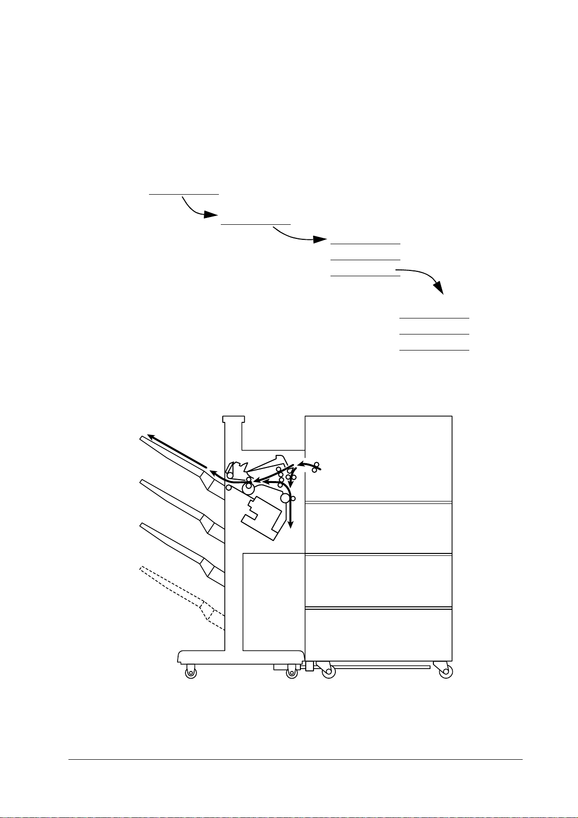
2.2 Basic operations
Outline
The finisher performs the face-down ejection and fa ce-up ejection of paper fed
through from the printer. The job offset and stapling functions are available with
face-down ejection.
These operations are controlled by the finisher driver’s circuit board.
OPERATION THEORY
Basic operations
Figure 2.1
Outline of the finisher
Outline of electrical circuits
The finisher’s operational sequence is controlled by the finisher driver’s circuit
board. A 16-bit microcomputer (CPU) is used in the finisher driver’s circuit board,
and this performed serial communications with the sequential control.
The finisher driver operates the solenoids and motors, etc., in accordance with the
various commands that are transmitted from the option controller via the serial
communications line. The finisher driver also notifi es the option controller of sensor and switch information via the serial communications line.
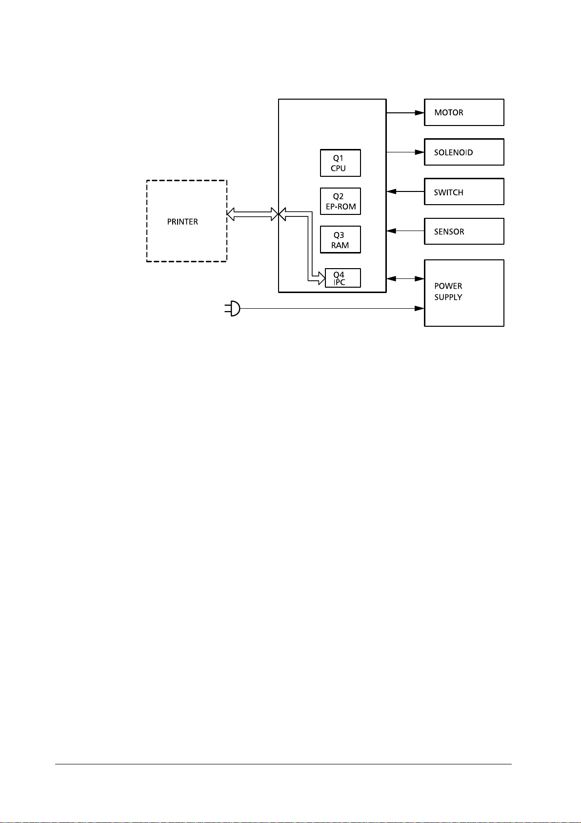
The major roles of the ICs mounted in the finisher driver are as follows.
Q1 (CPU). Sequential control.
•
Q2 (EP-ROM). Sequential programs built in.
•
Q3 (RAM). Used for backing up the initial data.
•
Q4 (IPC). Used for communications control.
•
The diagram below shows the signal flow between the finisher and the printer.
2-3
Page 4
OPERATION THEORY
Basic operations
Figure 2.2
Signal flow between the finisher and the printer
DF-30/DF-31
2-4
Page 5
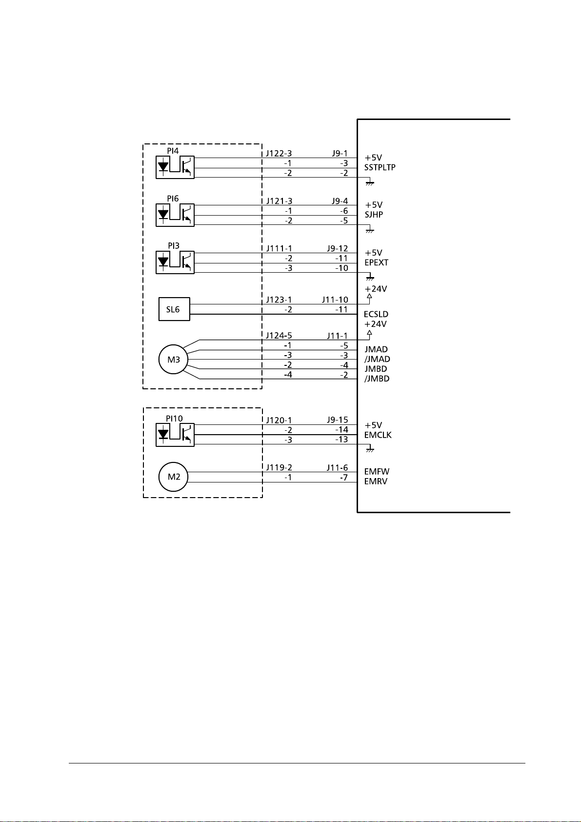
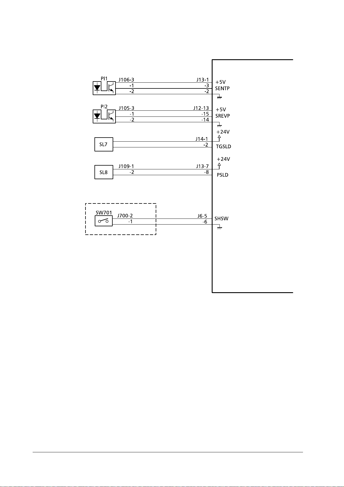
Finisher driver input/output
OPERATION THEORY
Basic operations
Staple tray paper
detection sensor
Matching board
home position
detection sensor
Paper ejectio n
detection sensor
Base board
shelter solenoi d
Matching board
movement mo tor
Staple tray assembly
Finisher driver circuit board
"L" when the sensor
detects paper.
"L" when the sensor
detects the matchi n g
board’s home position.
"L" when the sensor
detects paper.
The base board is
sheltered when "L".
Control signals for
the matching board
movement mo tor
Paper ejection
motor clock
detection sensor
Paper ejection
motor
Pulse emitted in
accordance with the
revolution speed of
the ejection motor
Control signals for
the paper ejection motor
2-5
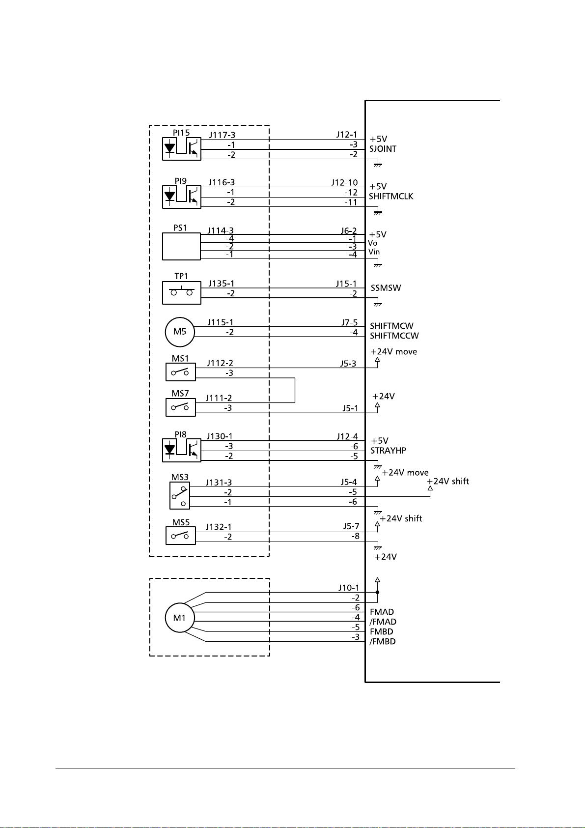
Page 6
OPERATION THEORY
Basic operations
Frame assembly
Joint sensor
Tray elevation
motor clock
detection sensor
Distance sensor
Tray elevation
motor temperature sensor
Tray elevation
motor
Top cover open/
close detection
switch
Front cover open/
close detection
switch
Tray home position detection
sensor
"L" when connected to the
printer.
Pulse emitted in
accordance with
the revolution
speed of the tray
elevation motor .
Control signal for
the distance sensor
"L" when the
temperature of
the tray elevation
motor is high.
Control signals for
the tray elevation
motor.
"L" when the sensor detection the
tray’s home position.
Safety area
detection switch
Tra y uppe r limit
detection switch
Feeder motor
Control signal for
the feeder mot o r.
DF-30/DF-31
2-6
Page 7
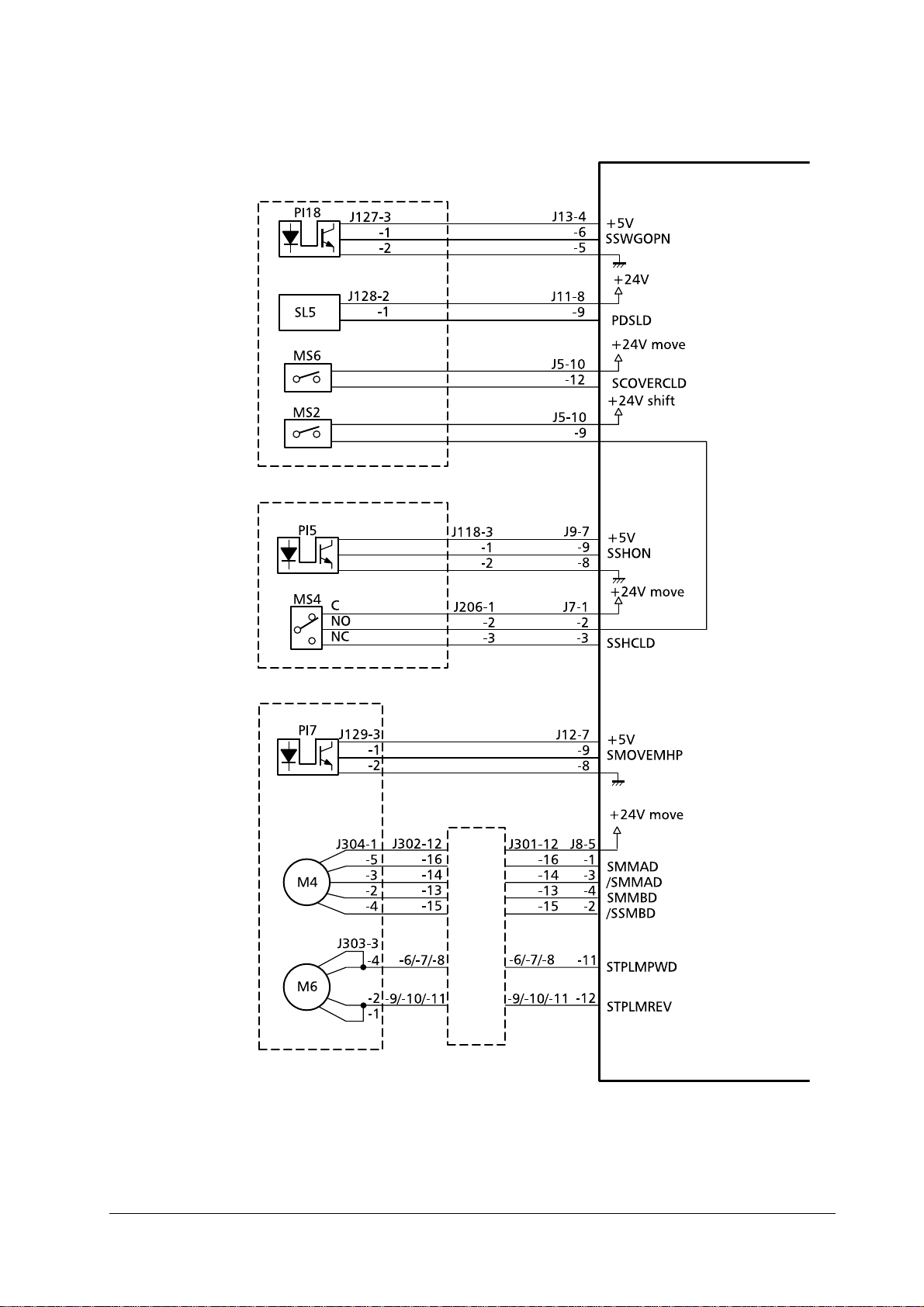
OPERATION THEORY
Basic operations
Swing guide
assembly detection sensor
Paddle drive solenoid
Swing guide
open/close detection switch
Swing guide
open/close detection switch
Shutter close
detection sensor
Shutter open
detection sensor
Swing guide assembly
Shutter guide assembly
Finisher driver circuit board
"L" when the
swing guide is
open.
Paddle revolves
when "L".
"H" when the
shutter is
closed.
"H" when the
shutter is closed
Stapler home
position detection sensor
Intermediate circuit board
Stapler move ment motor
Staple motor
Staple unit
"L" when the stapler’s home position is detected.
Liaision
board
Control signals for
the stapler movement motor.
Control signals
for the stapler
motor
2-7
Page 8
OPERATION THEORY
Basic operations
Finisher driver circuit board
Inlet paper
detection sensor
Inversion paper
detection sensor
Inversion roller
drive solenoid
Face-up flapper
solenoid
Staple exchange
completion
switch
"L" when the sensor detects
paper.
"L" when the sensor detects
paper.
Inversion roller
revolved when
"L".
Paper fed face-up
when "L".
Staple exchange completion
switch circuit board
Staple operations
started when "H".
DF-30/DF-31
2-8
Page 9
OPERATION THEORY
2.3 Feed and drive systems
Outline
This device stacks, shifts, staples and ejects paper to the tray in accordance with
the commands transmitted from the printer.
The four different methods of paper ejection are explained below.
Paper ejection methods
Face-down ejection
Feed and drive systems
Normal stacking
Job offset
Staple
One on the left-hand side
One on the right-hand side
Two in the center
Figure 2.3
Feed and drive sys tem
2-9
Page 10

OPERATION THEORY
Feed and drive systems
Face-down paper ejection
Normal stacking
The paper is ejected to the tray face down after being inverted.
Tray
Printed output
Top guide
Face-up tran sport
roller
Eject roller #1
Eject roller #2
Bottom guide
Tr ansport roller #2
Face-up
diverter
Transport
roller #1
Job offset
The job offset operates in two ways: First- page-only mode and whole-set-of-pages
mode.
In the first-page-only mode, the first piece of paper is inverted and fed through to
the staple tray . The piece of paper is then shifted forward by approximately 30mm,
and ejected face down to the tray.
The second and subsequent pieces of paper are inverted and ejected to the tray
without being fed into the staple tray.
DF-30/DF-31
•
First page
Tray
Swing guide
Paper ejection roller #1
Stopper
Feed roller #2
Paper ejection
roller #2
Staple tray
2-10
Page 11

•
Second and subsequent pages
Tray
Second and subsequent pages
First page
Swing guide
OPERATION THEORY
Feed and drive systems
Paper ejection roller #1
Tray
Stopper
Staple tray
Feed roller #2
In the whole set of pages mode (defa ult), the whole page of a print jo b is fed into the
staple tray so that the jop is shifted forward. The subsequent job as a whole is not
shifted but delivered in a normal manner, allowing every other job is shifted to
each other.
Stapling
The pages are inverted, stacked in the staple tray, stapled and then ejected to the
tray.
Tray
Paper
Staple
Swing guide
Tray
Stopper
Staple tray
2-11
Page 12

OPERATION THEORY
Feed and drive systems
Figure 2.4
One staple on the le ft-hand side (1)
One staple on the right-hand side (2, angled)
Positions of stapling
Paper width/2
Two staples in the center (3)
One staple on the right-hand side (2, horizontal)
Face-up paper ejection
Normal stacking
The paper is ejected face-up to the tray without being inverted.
Tray
Paper
1
2
3
Upper guide
Paper ejection roller #1
Paper ejection roller #2
Face-up feed roller
Lower guide
Test staples (Not used)
Feed roller #2
1
2
3
Face-up
diverter
Feed roller #1
DF-30/DF-31
Inversion roller
2-12
Page 13

OPERATION THEORY
Feed and drive systems
Feeding and ejection
Outline
When the paper fed through from the printer is to be laid face down in the tray, the
inversion operation is performed.
The feed motor (M1) is a stepping motor, and the paper ejection motor (M2) is a DC
motor. The forward and reverse operation for these motors is controlled by the
microcomputer (CPU) in the finisher driver’s circuit board.
Three photo-interrupters, the inlet paper detection sensor (P11), the inversion
detection sensor (P12) and the paper ejection detection sensor, are situated along
the paper’s feed route, and these check whether the paper has reached it s destination or is still in transit.
The finisher driver will judge that a paper jam has occurred if the paper does not
reach or pass each sensor within a pre-determined period of time. In this event,
operations are halted and notification of the jam is sent to the printer.
2-13
Page 14

OPERATION THEORY
Feed and drive systems
Finisher driver circuit board
Table 2.1 Detection signals
(1)
(2)
(3)
(4)
(5)
PS1:
PI1:
P12:
P13:
P14:
DF-30/DF-31
Staple tray pap er detection sign al
T ray stacking volume dete ct ion signal
Paper ejection detection signal
Inverted paper detection signal
Inlet paper detection signal
Distance senso r
Inlet paper detection sensor
Inverted paper detection sensor
Paper ejection detection sensor
Staple tray paper detection sensor
2-14
Page 15

OPERATION THEORY
Finisher driver circuit board
Feed and drive systems
Table 2.2 Motors/solenoids— (1 / 2)
M1:
M2:
M3:
M4:
M5:
SL5:
SL7:
SL8:
(1)
(2)
(3)
2-15
Feed moto r
Paper ejection motor
Matching board’s movement motor
Stapler movement motor
Tray elevation motor
Paddle drive solenoid
Inversion roller driver solenoid
Face-up flapper drive solenoid
Stapler movement motor drive signal
Tray elevation motor drive s ignal
Matching board movement motor drive signal
Page 16

OPERATION THEORY
Feed and drive systems
Table 2.2 Motors/solenoids— (2 / 2)
(4)
(5)
(6)
(7)
(8)
Paper ejectio n m o to r dr ive signal
Paddle solenoid drive signal
Feed motor drive signal
Inversion solenoid drive signal
Face-up flapper solenoid drive signal
Face-down feeder (inversion op erations)/paper ejection operations
The feeder motor (M1) and paper ejection motor (M2) are started up when the finisher driver receives a paper ejection signal from the printer, and feeder roller #1,
feeder roller #2, paper ejection roller #1 and paper ejection roller #2 are put into
motion. By starting up fee der ro lle r #1 , a si ngle s heet of pap er is t rans fe rred t o the
inverter . A paper detection s ensor (P11) located at the inlet detects the bottom edge
of the paper, and after transferring it to the prescribed position, the inversion roller
driver’s solenoid (SL7) is activated and the M1 driver starts up the inversion roller.
This conveys the paper through to an inverted position. On ce the paper has been
inverted, it is passed through to the feeder guide by the inversion roller operating
in the reverse direction. The paper is then fed and ejected by feeder roller #1,
feeder roller #2, paper ejection roller #1 and paper ejection roller #2.
Face-up feeder, paper ejection operations
When the paper trans ferred fr om the printer t o the tray is to b e ejec ted face up, the
feeder motor (M1) and th e paper ejecti on motor (M2) a re put into mo tion by a p aper
ejection signal received by the finisher driver from the printer, and the face-up
feeder roller, paper ejection roller #1 and pap er e jecti on ro lle r #2 ar e st ar ted up. At
the same time, the face-up flapper driver solenoid (SL8) is activated, and the flapper is switched across to the face-up side. This enables the paper to be fed and
ejected without being inverted.
Job offset
Shift operations move only the first piece of p aper or whole set of paper (default) fo r
each job, and eject the second and subsequent pieces of paper without moving
them.
The paper is moved with the matching board, and the matching board home position detection sensor (P16) detects whether this board is at the home position or
not.
The matching board movement motor (M3) is activated when the power supply is
switched on in order for the finisher driver to return the matching board to the
home position. If the matching board is already in the home position, the system
enters the stand-by mode. As the distance for moving the matc hing board is
extended when paper other tha n A3 and A4 (horizonta l) is us ed, the fi nisher dr iver
moves the matching board to the stand-by position.
1
The finisher driver hal ts the operation of the paper ejection motor (M2) after the
first piece of paper has passed the far end of paper ejection roller #1. The gear is
1. The stand-by position is 5mm outside of the paper’s edge.
DF-30/DF-31
2-16
Page 17

OPERATION THEORY
Feed and drive systems
then moved to the swing guide drive assembly after the M2 motor has been put into
reverse. This transmits the operation of M2 across to the gear and raises the swing
guide. The swing guide is raised until it is detected by the swing guide open detection sensor (PI18) and then halted.
The paper is returned to the staple tray by the rubber surface fitted to paper ejection roller #1 when the sw ing gui de is rais ed. Th e paper retu rned to the st aple tray
is then detected by the staple tray paper detection sensor (PI4).
The matching board movement motor (M3) is then activated and the paper moved
by 30mm. Depending on the size of the paper, there are cases where it cannot be
moved by 30mm as it will interfere with the left-hand edge. In this event, the base
board shelter solenoid (SL6) is set at ON, and the paper is moved 30mm after the
left-hand base board has been sheltered.
The finisher driver activates M3 in the reverse direction and moves the matching
board to the stand-by position after the paper has been moved.
The finisher driver then activates M2 in the reverse direction to lower the swing
guide. M2 is run in the forward direction when the swing guide open/close detection switch (MS2) is set at ON, and paper ejection roller #2 is activated. This ejects
the paper to the tray. The second and subsequent pieces of paper for each job are
ejected to the tray without shift movement.
Left-hand base board
Base board shelter solenoid
Matching
board
Matching board
home position
detection sensor
Matching board
movement motor
Paper
For information on modes of stapling available, see page 2-12.
2-17
Page 18

OPERATION THEORY
Feed and drive systems
Staple operations
Outline
The staple operations staple together a specified quantity of paper in the stapler
unit.
The position of the staples will differ in accordance with the stapler motor and the
size of the paper. Refer to table 2-2-1 for further details.
The stapler home position detection sensor (PI7) detects whether the stapler unit is
at the home position or not.
The finisher driver activates the stapler movement motor (M4) after receiving the
start signal from the printer, and moves the stapler unit to the central stand-by
position (note).
Note
Table 2.3 Positions of staples
The central stand-by position is the location where the stapler unit is situated prior to the
paper being returned to the stapler tray in order to prevent the stapler operations being rendered impos sible owing to th e paper curlin g u p in side the staple tray.
Staple mode A3 A4R
One, on left-hand side
One, on right-hand side
Two, centered
Test (Not used)
Refer to page 12, table 2.4 on (1) to (5) for details.
B5/
B4
(2) (3)
(4)
Ldg
(1)
(5)
Ltr/
Ltr A4 Lgl Otrs
R
DF-30/DF-31
2-18
Page 19

Stapler home
position sensor
OPERATION THEORY
Feed and drive systems
Paper
Stapler
movement
motor
Stapler unit
First page operations
The finisher driver halts the operation of the paper ejection motor (M2) after the
first piece of paper has passed the far end of paper ejection roller #1. The gear is
then moved to the swing guide drive assembly after the M2 motor has been put into
reverse. The swing guide is raised by M2 until it is detected by the swing guide
open detection sensor (PI18) and then halted. The paddle drive solenoid is then set
at ON, and the feed motor drive operates the paddle.
The paper is returned to the staple tray by the rubber surface fitted to paper ejection roller #1 when the swing guide is opened where it is detected by the staple tray
paper detection sensor (PI4).
The matching board movement motor (M3) is activated and the pieces of paper are
matched up.
2-19
Page 20

OPERATION THEORY
Feed and drive systems
Swing guide
Swing guide open
detection sensor
Swing guide open
detection switch
Paper ejection
roller #2
Swing guide
Fist page of paper
Paper ejection
roller #2
Tray
Feed m otor clock
detection sensor
Paper eject io n motor
Paper ejection roller #1
Rubber roller
Staple tray
DF-30/DF-31
Stapler unit
2-20
Page 21

OPERATION THEORY
Feed and drive systems
Second and subsequent page operations
The finisher driver halts the operation of the paper ejection motor (M2) when th e
bottom edge of the second and subsequent pieces of paper have passed 20mm
through paper ejection roller #1. The paddle drive solenoid is then set at ON, and
the feed motor (M1) drive ope rates the paddle. This returns the pa per to the s tapler
tray, activates the matching board movement motor (M3) and matches up the
pieces of paper.
Paddle
Paddle driver
solenoid
piece of pape r
Second and subsequent
pieces of paper
Swing guideSecond or the subsequent
First piece of paper
Stopper
Stapler unit
Paddle
Paper ejection roller #1
Rubber roller
Tray
Paper ejectio n
roller #2
Staple tray
Stapler unit
2-21
Page 22

OPERATION THEORY
Feed and drive systems
Last page operations
The finisher driver sta rts up M3 once again after the matching process has been
completed for the last piece of paper in order to move the matching board to the
staple matching position (note #1). The multiple sheets of paper are then matched
up and the motor halted. The finisher driver then activates M2 in the reverse direction and lowers the swing guide.
The finisher driver activates the stapling process in accordance with the specified
staple mode transmitted from the printer (refer to fig.2-2-12 on page 2-19) and staples the pages together.
The finisher driv er activat es M3 when t he stapli ng process has been completed an d
moves the matching bo ar d to t he shel ter p osi ti on ( not e #2 ) whe n t he p aper i s being
ejected. The paper ejection mot or (M2) is then ac tiva ted i n the forwa rd dir ectio n to
operate ejection ro ller #2 and eject the stapled pages to the tr ay.
Swing guide
Note
Paper ejection roller #2
Paper ejection motor
1. The staple matching position is 0.5mm inside the horizontal width of the pa per. 2. The shelter position during paper ejection is 5.0mm outside of the horizontal width of the paper.
DF-30/DF-31
2-22
Page 23

Swing guide
Paper
Paper ejection
roller #2
OPERATION THEORY
Feed and drive systems
Staple tray
Stapler unit
Tray operations
The finisher driver is equip ped wit h three trays , and pa per can be eject ed to ei ther
of these trays. The trays are moved upwards and downwards with the tray elevation motor (M5). The position of each tray is detected by the tray elevation motor
clock detection sensor (PI9) with the amount of encoder pulse s fitted to M5. The
tray home position detection sensor (PI8) detects whether the trays are at their
home positions or not.
2-23
Page 24

OPERATION THEORY
Feed and drive systems
Tr ay #1
Tr ay #2
Tray guide
T r ay upp er lim it detection
switch
Tr ay #3
Tray elevation motor
Safe area detection switch
The finisher driver raises and lowers the tray guide until it is aligned with the
paper ejection outlet specified by the printer.
The upper limit for the tray is detected by the tray upper limit detection switch
(MS5). The tray elevation motor (M5) is halted when the finisher driver sets MS5
to ON.
Tray elevation motor clock
detection sensor
Encoder
Tray home position sensor
DF-30/DF-31
The height of the paper eje c ted t o t he tray i s detect ed by t he d ista nce se nsor (PS1 ).
The tray is lowered when the height of the paper reaches the stipulated value.
The 24V power supply to the tray elevation motor is cut off and the finisher driver
operations halted if the safe area detection switch (MS3) is set at ON when the
shutter and swing guide are open.
The finisher driver will noti fy the printer that a fault has occurred with the tray
elevation motor in the following cases:
2-24
Page 25

OPERATION THEORY
Feed and drive systems
When the home position detection process does not end within 16.5 seconds of it starting.
1
When the tray elevation motor clock detection sensor (PI9) does not detect the tray eleva-
2
tion motor clock detection signal (SHIFTMCLK) within 0.2 seconds of tray elevation
starting.
When the tray upper limit detection switch (MS5) is set at ON during tray elevation.
3
Stapler unit
Staple operations are performed by the staple motor (M6), and stapling is completed for each revolution of the cam.
The home position for the cam is detected by the staple operation home position
detection sensor (PT2) being set at ON.
The forward and reverse operations of the staple motor (M6) are controlled by a
microcomputer (CPU) situated on the finisher driver circuit board.
The staple operations are returned to the initial status by the finisher driver operating M6 in the reverse direction when PT2 is OFF and continuing to operate until
PT2 is ON.
The staple detection sensor (PT1) detects where staples exist within the staple cartridge.
The staple motor (M6) cannot be operated unless the swing guide close detection
switches (MS2, MS6) are ON (with the swing guide closed). This is a safety protection function to prevent the stapler from operating when fingers are inside.
The finisher driver will notify the option controller of a fault with the staple motor
in the following cases:
When the home position detection process does not end within 0.5 seconds of it starting.
1
When the staple operation home position detection sensor (PT2) is not set at ON within
2
0.5 seconds of staple operations being started.
Also, the finisher driver will judge a staple jam if the staple operation home position detection sensor (PT2) is not set at ON within 0.5 seconds of it being set at
OFF after staple operations have been started, and the staple motor (M6) will be
operated in the reverse direction until PT2 is set at ON. The printer will also be
notified of the jam.
Staple cartridge
Staple ejection
plate
Staple anvil
Staple sensor
Staple motor
Staple operation home position sensor
2-25
Page 26

OPERATION THEORY
Feed and drive systems
Cam
Tray loading volume detection
The number of pages and stacks (staple number) of paper ejected to the tray is
recorded by the finisher driver, and the height of the paper surface is detected by
the distance sensor (PS1). The maximum amount of paper that can be stacked in
each tray is shown in the table below.
The finisher driver will halt operations when the conditions outlined in the table
have been satisfied, and the printer will be notified that the tray is full.
Table 2.4 Loding capacities
Tray #
Tray #1 88mm 88mm, 300 pages or 30 stacks 48mm, 300 pages or 30 stacks
Tray #2 95mm 95mm, 300 pages or 30 stacks 48mm, 300 pages or 30 stacks
Tray #3 95mm 95mm, 300 pages or 30 stacks 48mm, 300 pages or 30 stacks
Stacking mode details
Mode #1.
For the normal stacking of pages of the same size, of small sizes1 or dur-
ing job offset.
Mode #2.
When height, number of pages and number of stacks are relevant for sta-
ples only.
Tray mode (See
12 3
details
below.)
(note #3)
(note #3)
(note #3)
Mode #3.
sizes
Note
1. Small sizes include A4 vertical/horizontal, letter vertical/horizontal, B5 and A5
2. Large sizes include A3, B4, legal and ledger
DF-30/DF-31
Number of pages and stacks are only relevant for stapled paper.
Other cases (cross-mode stacking and cross-s ize stacking, including large
2
).
2-26
Page 27

OPERATION THEORY
Feed and drive systems
Distance sensor
Paper
Jam detection
The printer is equipped with the fol lowing paper detection sen sors to determine the
existence of paper and to determine that the paper is being fed correctly:
•
- Inlet paper detection sensor (PI1)
•
- Paper inversion detection sensor (PI2)
•
- Paper ejection detection sensor (PI3)
A jam is determined by detecting if the paper has been fed through to the sensor at
a certain time pre-set in the microcomputer (CPU) located on the finisher driver.
The finisher’s paper ejection operations are halted if the CPU determines that a
jam has occurred, and this is notified to the printer.
Delayed jam (delayed jam at the inlet sensor).
The CPU determines a delayed jam if the
paper does not arrive at the inlet’ s de tection sens or despite b eing fed the prescribed
distance (approximately 300mm) after the paper ejection signal is received from
the printer.
L1 = approximately 300mm
PINT
L1
Jam check
PINT
L1
Paper ejection signal
Inlet paper detection sensor (PI1)
Feeder motor (M1)
2-27
Normal
Abnormal
Page 28

OPERATION THEORY
Feed and drive systems
Accumulated jam #1 (inlet sensor accumulated jam).
lated jam has occurred when the inlet paper d etection sensor (PI1) detects t he front
edge of the paper but not the back edge after the paper has been fed the stipulated
distance.
Jam check
Inlet paper detection sensor (PI1)
Feed motor (M1)
L2 = the approximate size of the paper X 2mm
Accumulated jam #2 (paper ejection detection sensor delayed jam).
an accumulated jam has occurred when the inlet paper detection sensor (PI1)
detects the front edge of the paper but the paper does not arrive at the paper ejection detection sensor (PI3 ) even after the paper has been fed the stipulated distance.
PINT
L
L
Normal
The CPU judges that an accumu-
PINT
L
L
Abnormal
The CPU judges that
Inlet paper detection sensor (PI1)
Jam check
Paper ejection detection sensor (PI3)
Feed motor (M1)
L3 = approximately 360mm (for straight paper ejection), approximately 340mm (for inverted
paper ejection)
Accumulated jam #2 (paper ejection detection sensor delayed jam).
an accumulated jam has occurred when the paper ejection detection sensor (PI3)
detects the front edge of the paper but not the back edge after the paper has been
fed the stipulated distance.
PINT
L
Normal
PINT
L
Abnormal
The CPU judges that
DF-30/DF-31
2-28
Page 29

OPERATION THEORY
Feed and drive systems
Jam check
Inlet paper detection sensor (PI3)
Feed motor (M1)
L4 = the approximate size of the paper X 2mm
Power on jam.
The CPU judges that a po wer on jam ha s occurred if paper i s det ected
by either the inlet paper detec tion sensor (PI1 ), the inverted pa per detectio n sensor
(PI2) or the paper ejection detection sensor (PI3) when the power supply to the finisher is switched on.
PINT
L
Normal
PINT
L
Abnormal
2-29
Page 30

OPERATION THEORY
Power supply
2.4 Power supply
Outline
This devices uses a remote switch system for the power supply.
The printer outputs a power on signal (PWRON-IN) to the power supply assembly
when the power switch to the printer is turned on, and the power supply is
switched on. The power supply circuit supplies +24V to the finisher driver when
the PWRON-IN signal is "H".
This +24V is used to drive the feed motor, paper ejection motor, solenoids and other
elements. The finisher driver generate +5V, which is used for the sensors and the
integrated circuits in the finisher driver’s circuit board.
A block diagram is provided below.
Protection functions
The +24V power supply circuit is equipped with an excess current protection circuit
to automatically cut off the output voltage when short circuits or other trouble is
triggered and excess currents flow in order to prevent the power supply circuit
from being damaged.
Consequently, the power switch to the printer is switched off when the excess current protection function is activated and no DC voltage is output from the power
supply circuit, and the power is switched on again after the trouble with the load
has been repaired.
DF-30/DF-31
2-30
 Loading...