

Page 1

Chapter 3 MECHANICAL SYSTEM
Contents
General 2
External control 2
External cover 2
Front door assembly 3
Rear cover 3
Upper door assembly 4
Right-hand cover assembly 4
Upper cover 5
Front cover 6
Tray assembly 7
Slat upper guide 7
Slat lower guide 8
Feeder 9
Staple tray unit 9
Removing the staple tray unit from the main unit 9
Dismantling and assembly 10
Boards 21
Finisher driver circuit board 21
Lithium battery 22
Power supply unit 23
Interface circuit board 24
Staple exchange completion switch circuit board 25
Page 2
MECHANICAL SYSTEM
General
3.1 General
This chapter explains the mechanical features, operations and procedures for dismantling and assembling the finisher driver. Ensure that the following precautions
are observed when proceeding with these tasks.
Caution Always disconnect the power supply from the socket when dismantling or reas-
sembling the device.
Unless otherwise stated, assembly procedures should be performed in the reverse
sequence to dismantling.
Care must be taken not to use the wrong screws (length, diameter) during assembly.
Never attempt to operate the device with parts removed.
Discharge static electricity from the body by touching a metal part of the printer
prior to removing or replacing circuit boards to prevent them from being d amaged through static electricity.
External control
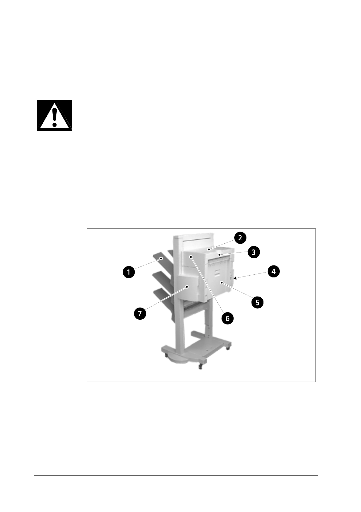
External cover
DF-30/DF-31
1. Tray
2. Upper door assembly
3. Upper cover assembly
4. Rear cover
5. Left-hand cover assembly
6. Front cover
7. Front door assembly
3-2
Page 3
MECHANICAL SYSTEM
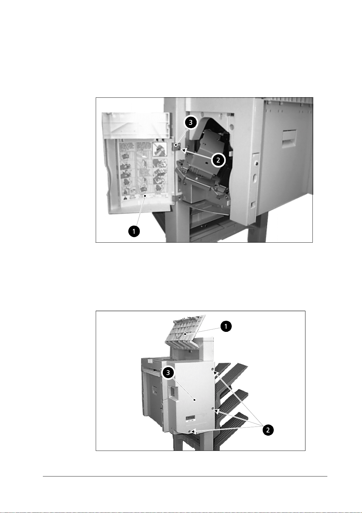
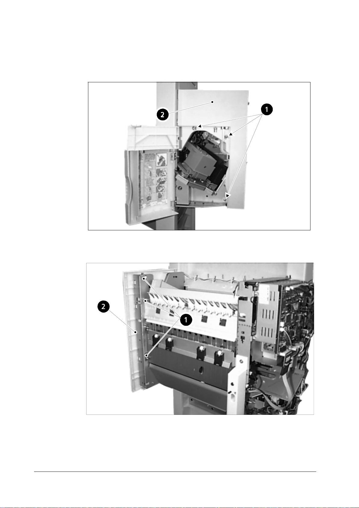
Front door assembly
Open the front door assembly.
1
Remove the single screw.
2
Lift off the door assembly after removing the bearings.
3
General
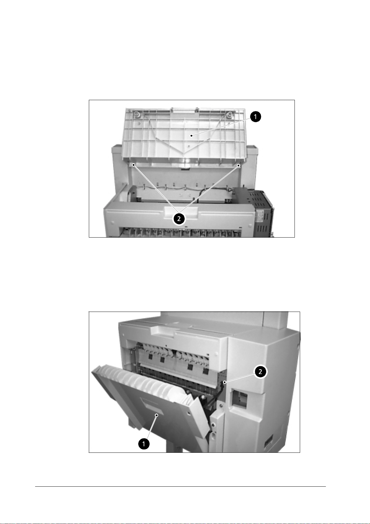
Rear cover
Open the upper door assembly
1
Remove the three screws
2
Lift out the rear cover.
3
3-3
Page 4
MECHANICAL SYSTEM
General
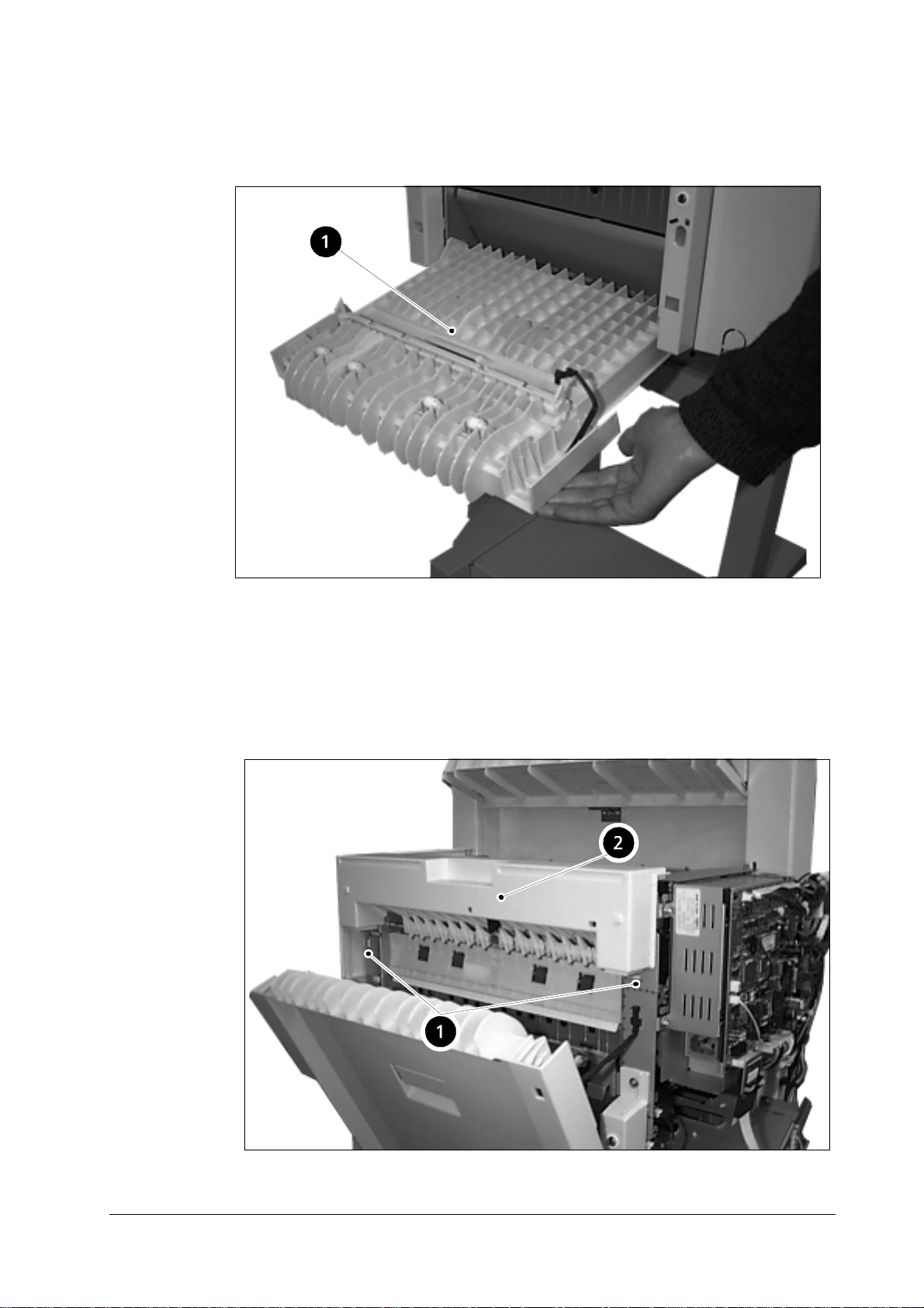
Upper door assembly
Open the upper door assembly.
1
Undo the two clips and remove the upper door assembly.
2
Right-hand cover assembly
Open the right-hand cover assembly.
1
Remove the hinge.
2
DF-30/DF-31
3-4
Page 5
MECHANICAL SYSTEM
Remove the right-hand cover by pulling it out from the front.
3
General
Upper cover
Open the upper cover assembly
1
Remove the rear cover assembly
2
Open the left-hand cover assembly
3
Undo the two clips (➊ below) and lift the upper cover (➋ below) out.
4
3-5
Page 6
MECHANICAL SYSTEM
General
Front cover
Remove the three screws (➊ below) that secure the front cover (➋ below).
1
Undo the three c lips (➊ below) and remove the front cover (➋ below).
2
DF-30/DF-31
3-6
Page 7
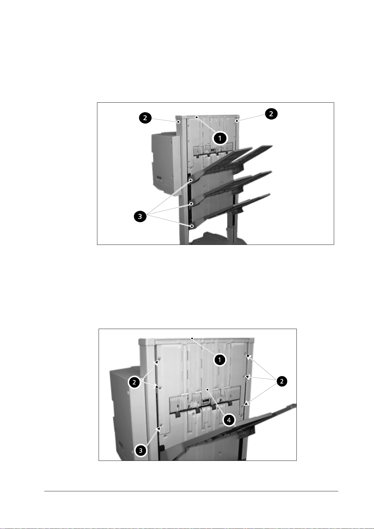
Tray assembly
Remove the slide guide assembly
1
Remove the stopper
2
Lift out the tray assembly
3
MECHANICAL SYSTEM
General
Slat upper guide
Remove the slide guide (➊ below).
1
Remove the five screws (➋, 4M, below).
2
Remove the single screw (➌, 3M, below) and remove the slat upper guide (➍
3
below).
3-7
Page 8
MECHANICAL SYSTEM
General
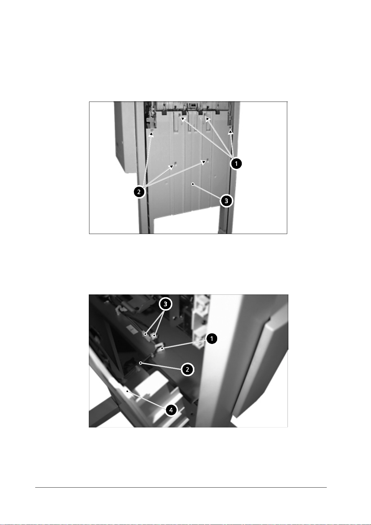
Slat lower guide
Remove the slide guide.
1
Remove the three screws (4M).
2
Remove the three screws (3M) and pull the slat lower guide forward.
3
Remove the flux lines (➋ below) from the flux line fa stener (➊ below).
4
Remove the two connectors (➌ below) and remove the slat lower guide (➍
5
below).
DF-30/DF-31
3-8
Page 9

3.2 Feeder
Staple tray unit
Removing the staple tray unit from the main unit
Remove the rear cover.
1
Remove the slat upper guide and the slat lower guide.
2
Remove the two connectors (➊ below).
3
MECHANICAL SYSTEM
Feeder
Remove the flux lines (➋ below) from the flux li ne fastener (➊ below).
4
Remove the two connectors (➌ below).
5
3-9
Page 10

MECHANICAL SYSTEM
Feeder
Remove the three screws and then the staple tray unit
6
Dismantling and assembly
Paper ejection motor
Remove the single screw (➊ below) and then remove the motor cover (➋
1
below).
Remove the two screws (➌ below) and then remove the paper ejection motor
2
(➍ below).
DF-30/DF-31
3-10
Page 11

MECHANICAL SYSTEM
Matching board movement motor
Remove the single connector (➊ below).
1
Remove the two screws (➋ below) and then remove the matching board move-
2
ment motor (➌ below).
Feeder
Paper ejection roller #1
Undo the clip and remove the arm.
1
Remove the two rollers.
2
Remove the two screws and then remove the staple guide.
3
Remove the E-shaped fastening ring (➊ below) and then remove the single
4
bearing (➋ below).
Slide them in the direction of the arrow and then remove the paper ejection
5
roller (➌ below).
3-11
Page 12

MECHANICAL SYSTEM
Feeder
Remove the single E-shaped fastening ring (➋ below) from the paper ejection
6
roller (➊), and then remove the single cam (➌), the single gear (➍), the single
horizontal pin and the single bearing (➎).
Remove the single E-shaped fastening ring (➋ below) from the paper ejection
7
roller (➊), and then remove the single horizontal pin (➌) and the single gear
(➍).
DF-30/DF-31
3-12
Page 13

MECHANICAL SYSTEM
Feeder
Face-up flapper solenoid
Remove the face-up flapper sol enoid (➋ below) from the main unit:
Remove the rear cover and the upper cover.
1
Remove the power supply assembly in accordance with the procedures
2
explained between 1) and 4) on page 3-23,
Remove the single connector (➊ below).
3
Power supply unit
.
Remove the two screws (➊ below) from inside the unit, and then remove the
4
face-up flapper solenoid (➋).
3-13
Page 14

MECHANICAL SYSTEM
Feeder
Staple assembly
Remove the staple assembly from the device:
Remove the rear cover.
1
Remove the single screw (➋) and then remove the circuit board cover (➊).
2
DF-30/DF-31
Remove the single connector (J8 finisher driver, ➊). Detach the flexib le cable
3
from the guide.(➋=circuit board cover)
3-14
Page 15

MECHANICAL SYSTEM
Feeder
4) Perform the procedure explained between 1) and 6) on page 3-6 to remove
4
the staple tray unit.
5) Remove the flux line fastener and the flux line band, and then remove the
5
single connector.
6) Remove the tw o screws
6
Remove the two screws and then remove the staple assembly
7
3-15
Page 16

MECHANICAL SYSTEM
Feeder
Tray drive assembly
Remove the tray driver assembly from the device :
Perform the procedure explained on page 3-9,
1
Staple tray unit
staple tray unit.
Remove the E-shaped fastener ring (➊) and then remove the bearing (➋).
2
Remove the two screws (➌) and then remove the cover (➍).
3
to remove the
DF-30/DF-31
Remove the two connectors (➊).
4
3-16
Page 17

MECHANICAL SYSTEM
Feeder
Remove the flux line fastener (➊).
5
Remove the four connectors (➋).
6
Remove the three screws (➊) and then remove the tray drive assembly (➋).
7
3-17
Page 18

MECHANICAL SYSTEM
Feeder
Feed motor
Remove the feed motor from the device:
Perform the procedure explained on page 3-23,
1
Power supply unit
the power supply unit.
Remove the C-shaped fastener ring and then remove the single gear.
2
Remove the two screws and then remove the feed motor from inside the unit.
3
, to remove
DF-30/DF-31
3-18
Page 19

MECHANICAL SYSTEM
Inversion roller
Remove the inversion roller from the device:
Perform the procedure explained on page 3-23,
1
Power supply unit
the power supply unit.
Remove the single screw (➊) and then remove the inversion solenoid (➋).
2
Remove the single spring (➌).
3
Remove the E-shaped fastener ring (➍) and then remove the two gears (➎).
4
Feeder
to remove
Remove the single bearing
5
Remove the single spring restraint (➊) and then remove the single spring (➋).
6
Remove the E-shaped fastening ring (➌) and the single bearing (➍), and then
7
remove the inversion roller (➎).
3-19
Page 20

MECHANICAL SYSTEM
Feeder
DF-30/DF-31
3-20
Page 21

3.3 Boards
Finisher driver circuit board
Remove the finisher driver circuit board from the device:
Remove the rear cover.
1
Remove all the connectors.
2
Remove the four screws (➊) and then remove the finisher driver circuit board
3
(➋).
MECHANICAL SYSTEM
Boards
3-21
Page 22

MECHANICAL SYSTEM
Boards
Lithium battery
Caution Replace the lithium battery with SONY Lithium Cell CR2450 only. Use of another
battery may pres ent a risk of fire or explosion.
The lithium battery includes lithium, an organic catalyst and other flammable sub-
stances. The battery may present a fire or chemical burn hazard if misteated. Do
not recharge, disassemble, or dispose of in fire.
Caution Keep the battery out of reach of children and discard used battery promptly.
When disposing the lithium battery, observe the applicable local lows and ordinances.
The package of lithium battery includes a se al (➌) in order to prevent short-circuit.
When you replace the batte ry (➋), be sure to seal the new battery after you set it on
the board (➊).
DF-30/DF-31
3-22
Page 23

MECHANICAL SYSTEM
Power supply unit
Remove the power supply unit from the device:
Perform the procedure explained between 1) and 4) on page 3-14 to remove the
1
finisher driver circuit board.
Remove the single 3M screw (➊) and the three 4M screws (➋), and then
2
remove the power supply unit (➌).
Boards
Remove the flux line fastener (➋) from the power supply unit (➊) and then
3
remove the single connector (➌).
Remove the three screws (➋) from the power supply unit (➊) and then remove
4
the cover (➌).
3-23
Page 24

MECHANICAL SYSTEM
Boards
Interface circuit board
Remove the interface circuit board from the device:
Remove the rear cover.
1
Remove the three connectors (➊).
2
Remove the two screws (➋) and then remove the interface circuit board (➌).
3
DF-30/DF-31
3-24
Page 25

MECHANICAL SYSTEM
Boards
Staple exchange completion switch circuit board
Remove the staple exchange completion switch circuit board from the device:
Remove the front cover.
1
Remove the single connector (➊).
2
Remove the single screw (➋) and then remove the staple exchange completion
3
switch circuit board (➌).
3-25
Page 26

MECHANICAL SYSTEM
Boards
This page left intentionally blank
DF-30/DF-31
3-26
 Loading...