

Page 1

R
DC-2050
DC-2050
SERVICE
MANUAL
Published in Oct. ’99
841AF110
DC-2050 (MCE) S/M
Page 2

CAUTION
Danger of explosion if battery is incorrectly replaced.
Replace only with the same or equivalent type recommended
by the manufacturer. Dispose of used batteries according to
the manufacturer’s instructions.
CAUTION
Double-pole/neutral fusing.
Page 3

SERVICE
MANUAL
DC-2050
Page 4

R
Safety precautions
This booklet provides safety warnings and precautions for our service
personnel to ensure the safety of their customers, their machines as well
as themselves during maintenance activities. Service personnel are
advised to read this booklet carefully to familiarize themselves with the
warnings and precautions described here before engaging in
maintenance activities.
Page 5
Safety warnings and precautions
Various symbols are used to protect our service personnel and
customers from physical danger and to prevent damage to their
property. These symbols are described below:
DANGER: High risk of serious bodily injury or death may result from
insufficient attention to or incorrect compliance with warning
messages using this symbol.
WARNING: Serious bodily injury or death may result from insufficient
attention to or incorrect compliance with warning messages
using this symbol.
CAUTION: Bodily injury or damage to property may result from
insufficient attention to or incorrect compliance with warning
messages using this symbol.
Symbols
The triangle (
and caution. The specific point of attention is shown inside
the symbol.
) symbol indicates a warning including danger
General warning.
Warning of risk of electric shock.
Warning of high temperature.
indicates a prohibited action. The specific prohibition is
shown inside the symbol.
General prohibited action.
Disassembly prohibited.
Page 6
indicates that action is required. The specific action
required is shown inside the symbol.
General action required.
Remove the power plug from the wall outlet.
Always ground the copier.
1. Installation Precautions
WARNING
• Do not use a power supply with a voltage other than that specified.
Avoid multiple connections to one outlet: they may cause fire or electric
shock. When using an extension cable, always check that it is
adequate for the rated current. ...............................................................
• Connect the ground wire to a suitable grounding point. Not grounding
the copier may cause fire or electric shock. Connecting the earth wire
to an object not approved for the purpose may cause explosion or
electric shock. Never connect the ground cable to any of the following:
gas pipes, lightning rods, ground cables for telephone lines and water
pipes or faucets not approved by the proper authorities.........................
CAUTION
• Do not place the copier on an infirm or angled surface: the copier may
tip over, causing injury. ...........................................................................
• Do not install the copier in a humid or dusty place. This may cause fire
or electric shock......................................................................................
• Do not install the copier near a radiator, heater, other heat source or
near flammable material. This may cause fire. .......................................
• Allow sufficient space around the copier to allow the ventilation grills to
keep the machine as cool as possible. Insufficient ventilation may
cause heat buildup and poor copying performance................................
Page 7

• Always handle the machine by the correct locations when moving it. ....
• Always use anti-toppling and locking devices on copiers so equipped.
Failure to do this may cause the copier to move unexpectedly or
topple, leading to injury. ..........................................................................
• Avoid inhaling toner or developer excessively. Protect the eyes. If toner
or developer is accidentally ingested, drink a lot of water to dilute it in
the stomach and obtain medical attention immediately. If it gets into the
eyes, rinse immediately with copious amounts of water and obtain
medical attention.....................................................................................
• Advice customers that they must always follow the safety warnings and
precautions in the copier’s instruction handbook. ...................................
2. Precautions for Maintenance
WARNING
• Always remove the power plug from the wall outlet before starting
machine disassembly. ............................................................................
• Always follow the procedures for maintenance described in the service
manual and other related brochures. ......................................................
• Under no circumstances attempt to bypass or disable safety features
including safety mechanisms and protective circuits. .............................
• Always use parts having the correct specifications. ...............................
• Always use the thermostat or thermal fuse specified in the service
manual or other related brochure when replacing them. Using a piece
of wire, for example, could lead to fire or other serious accident............
• When the service manual or other serious brochure specifies a
distance or gap for installation of a part, always use the correct scale
and measure carefully. ...........................................................................
• Always check that the copier is correctly connected to an outlet with a
ground connection. .................................................................................
Page 8
• Check that the power cable covering is free of damage. Check that the
power plug is dust-free. If it is dirty, clean it to remove the risk of fire or
electric shock. .........................................................................................
• Never attempt to disassemble the optical unit in machines using lasers.
Leaking laser light may damage eyesight...............................................
• Handle the charger sections with care. They are charged to high
potentials and may cause electric shock if handled improperly..............
CAUTION
• Wear safe clothing. Avoid wearing loose clothing or accessories such
as ties which may be caught in rotating sections....................................
• Use utmost caution when working on a powered machine. Keep away
from chains and belts..............................................................................
• Handle the fixing section with care to avoid burns as it can be
extremely hot..........................................................................................
• Check that the fixing unit thermistor, heat and press rollers are clean.
Dirt on them can cause abnormally high temperatures. .........................
• Do not remove the ozone filter, if any, from the copier except for
routine replacement. ...............................................................................
• Do not pull on the AC power cord or connector wires on high-voltage
components when removing them; always hold the plug itself...............
• Do not route the power cable where it may be stood on or trapped. If
necessary, protect it with a cable cover or other appropriate item. ........
• Treat the ends of the wire carefully when installing a new charger wire
to avoid electric leaks. ............................................................................
• Remove toner completely from electronic components..........................
• Run wire harnesses carefully so that wires will not be trapped or
damaged.................................................................................................
Page 9
• After maintenance, always check that all the parts, screws, connectors
and wires that were removed, have been refitted correctly. Special
attention should be paid to any forgotten connector, trapped wire and
missing screws. ......................................................................................
• Check that all the caution labels that should be present on the machine
according to the instruction handbook are clean and not peeling.
Replace with new ones if necessary.......................................................
• Handle greases and solvents with care by following the instructions
below: .....................................................................................................
· Use only a small amount of solvent at a time, being careful not to
spill. Wipe spills off completely.
· Ventilate the room well while using grease or solvents.
· Allow applied solvents to evaporate completely before refitting the
covers or turning the main switch on.
· Always wash hands afterwards.
• Never dispose of toner or toner bottles in fire. Toner may cause
sparks when exposed directly to fire in a furnace, etc. .........................
• Should smoke be seen coming from the copier, remove the power
plug from the wall outlet immediately. ..................................................
3. Miscellaneous
WARNING
• Never attempt to heat the drum or expose it to any organic solvents
such as alcohol, other than the specified refiner; it may generate toxic
gas. .........................................................................................................
Page 10

CONTENTS
I THEORY AND CONSTRUCTION SECTION
1-1 Specifications
1-1-1 Specifications ................................................................................ 1-1-1
1-2 Handling Precautions
1-2-1 Drum ............................................................................................. 1-2-1
1-2-2 Developer and toner...................................................................... 1-2-1
1-3 Mechanical Construction
1-3-1 Part names and their functions ..................................................... 1-3-1
1-3-2 Machine cross section................................................................... 1-3-3
1-3-3 Drive system ................................................................................. 1-3-4
1-3-4 Mechanical construction ................................................................ 1-3-6
II ELECTRICAL SECTION
2-1 Electrical Parts Layout
2-1-1 Electrical parts layout .................................................................... 2-1-1
2-2 Detection of Paper Misfeed
2-2-1 Paper misfeed detection ............................................................... 2-2-1
2-2-2 Paper misfeed detection conditions .............................................. 2-2-2
2-3 Operation of the PCBs
2-3-1 Composite PCB............................................................................. 2-3-1
2-3-2 Main PCB ...................................................................................... 2-3-3
2-3-3 Operation unit PCB ........................................................................ 2-3-8
III SET UP AND ADJUSTMENT SECTION
3-1 Installation
3-1-1 Unpacking and installation ............................................................ 3-1-1
3-1-2 Setting initial copy modes ........................................................... 3-1-16
3-1-3 Installing the key counter (option) ............................................... 3-1-17
3-1-4 Installing the dehumidifier (service part) ..................................... 3-1-19
3-2 Simulation
3-2-1 Simulations.................................................................................... 3-2-1
3-3 Assembly and Disassembly
3-3-1 Precautions for assembly and disassembly .................................. 3-3-1
3-3-2 Paper feed section ........................................................................ 3-3-3
3-3-3 Main charging section ................................................................. 3-3-17
3-3-4 Exposure section......................................................................... 3-3-20
3-3-5 Drum section ............................................................................... 3-3-40
3-3-6 Developing section ...................................................................... 3-3-46
3-3-7 Transfer and separation section.................................................. 3-3-49
3-3-8 Cleaning section.......................................................................... 3-3-54
3-3-9 Fixing and eject section............................................................... 3-3-57
3-3-10 Others ......................................................................................... 3-3-67
3-4 PCB Initial Settings
3-4-1 Replacing the main PCB ............................................................... 3-4-1
3-4-2 Adjustment-free variable resistors (VR) ........................................ 3-4-4
3-5 Self Diagnostics
3-5-1 Self-diagnostic function ................................................................. 3-5-1
1AF
1-1-1
Page 11

1AF
3-6 Troubleshooting
3-6-1 Image formation problems ............................................................ 3-6-1
3-6-2 Paper misfeeds ........................................................................... 3-6-16
3-6-3 PCB terminal voltages ................................................................. 3-6-19
3-6-4 Electrical problems ...................................................................... 3-6-30
3-6-5 Mechanical problems .................................................................. 3-6-38
3-7 Appendixes
Timing chart No. 1 ...................................................................................... 3-7-1
Timing chart No. 2 ...................................................................................... 3-7-2
Timing chart No. 3 ...................................................................................... 3-7-3
Composite PCB 1/3 .................................................................................... 3-7-4
Composite PCB 2/3 .................................................................................... 3-7-5
Composite PCB 3/3 .................................................................................... 3-7-6
Operation unit PCB..................................................................................... 3-7-7
Main PCB ................................................................................................... 3-7-8
General connection diagram ...................................................................... 3-7-9
General wiring diagram ............................................................................ 3-7-10
1-1-2
Page 12

I
THEOR Y AND
CONSTRUCTION
SECTION
I Theory and
Construction Section
DC-2050 (MCE) S/M
Page 13

CONTENTS
1-1 Specifications
1-1-1 Specifications...................................................................................... 1-1-1
1AF
1-1-5
Page 14

1AF
1-1-6
Page 15

1AF
1-1-1 Specifications
Type ……………………………Desktop
Copying system ………………Dry, indirect electrostatic system
Originals ………………………Sheets, books and 3-dimensional
Maximum size: A3/11" × 17"
Original feed system …………Fixed
Copy paper …………………… Plain paper: 60 – 80 g/m2 for drawer feed
60 – 200 g/m2 for bypass feed
Special paper: OHP film, colored paper and letter head
Note: Use the bypass for special paper.
Copying sizes …………………Maximum: A3/11" × 17"
Minimum: A6R/51/2" × 81/2"
Magnification ratios …………… 64 – 141%, 1% increments
Fixed ratios:
Metric
1:1 ± 0.8%, 1:1.410/1:1.270/1:1.220/1:1.150/1:1.100/
1:1.060/1:0.910/1:0.900/1:0.860/1:0.810/1:0.770/
1:0.750/1:0.700/1:0.650/1:0.640
Inch
1:1 ± 0.8%, 1:1.290/1:1.210/1:0.780/1:0.770/1:0.730/
1:0.640
Copy speeds…………………… At 100% magnification:
A4/11" × 81/2": 20 copies/min.
A3/11" × 17": 12 copies/min.
B4 (257 × 364 mm)/81/2" × 14": 13 copies/min.
First copy time ………………… 4.9 s or less (A4/11" × 81/2", 100% magnification,
manual exposure)
Warm-up time ………………… 45 s or less (room temperature 20°C/68°F, 65% RH)
Paper feed system ……………Automatic feed from the paper drawer
Capacity: 250 sheets of 80 g/m
Manual feed from the bypass table
Capacity: 50 sheets of 80 g/m
Multiple copying ……………… 1 – 100 copies
Photoconductor ……………… OPC (drum diameter 60 mm)
Charging system ……………… Single positive corona charging (drum potential: 850 V DC)
Exposure system ………………Slit exposure
Lens …………………………… Fixed-focal lens, f: 215 mm, F8.0
Light source ……………………Halogen lamp, 350 W
Developing system ……………Dry, magnetic brush
Developer: 2-component, ferrite carrier and N27T black
toner
Toner density control: toner sensor
Toner replenishing: automatic from a toner hopper
Transfer system ……………… Single positive corona charging, 5.2 kV DC
Separation system …………… Single AC corona charging, 4.1 kV AC
2
2
1-1-1
Page 16

1AF
Fixing system …………………Heat roller
Heat source: halogen heater (980 W)
Control temperature: 175°C/347°F (at normal ambient
temperature)
Abnormally high temperature protection devices:
140°C/284°F and 150°C/302°F thermostats
Fixing pressure: 127.4 N
Charge erasing system ……… Exposure by cleaning lamp
Cleaning system ……………… Cleaning blade
Functions ……………………… (1) Self-diagnostics
(2) Simulation
(3) Auto clear (30 – 270 s, in intervals of 30 s)
(4) Auto start
(5) Auto shutoff (15 – 120 min, in intervals of 15 min)
(6) Auto preheat/energy saving (5 – 45 min,
in intervals of 5 min)
(7) Auto exposure
(8) Photo mode
(9) Manual magnification selection
(10) Auto magnification selection (by original size entry)
(11) Auto paper selection (by original size entry)
(12) Auto selection (when the ADF is used)
Power source …………………220 – 240 V AC, 50/60 Hz, 6.3 A
Rated power consumption …… 1450 W
Dimensions ……………………775 (W) × 590 (D) × 375 (H) mm
301/2" (W) × 231/4" (D) × 143/4" (H)
Weight …………………………Approx. 39 kg/85.8 lbs.
Floor requirements …………… 1145 (W) × 590 (D) mm
451/16" (W) × 231/4" (D)
Accessories …………………… Copy tray
Options …………………………Key counter, ADF
1-1-2
Page 17

CONTENTS
1-2 Handling Precautions
1-2-1 Drum ................................................................................................... 1-2-1
1-2-2 Developer and toner ........................................................................... 1-2-1
1AF
1-1-7
Page 18

1AF
1-1-8
Page 19

1AF
1-2-1 Drum
Note the following when handling or storing the drum.
• When removing the image formation unit, never expose the drum surface to strong direct
light.
• Keep the drum at an ambient temperature between –20°C/ –4°F and 40°C/104°F and at
a relative humidity not higher than 85%RH. Avoid abrupt changes in temperature and
humidity.
• Avoid exposure to any substance which is harmful to or may affect the quality of the drum.
• Do not touch the drum surface with any object. Should it be touched by hands or stained
with oil, clean it.
• If the machine is left open for more than 5 minutes for maintenance, remove the drum and
store it in the drum storage bag (P/N 78369020).
1-2-2 Developer and toner
Store the developer and toner in a cool, dark place. Avoid direct light, high humidity and
temperature.
1-2-1
Page 20

CONTENTS
1-3 Mechanical Construction
1-3-1 Part names and their functions ........................................................... 1-3-1
1-3-2 Machine cross section ........................................................................ 1-3-3
1-3-3 Drive system ....................................................................................... 1-3-4
1-3-4 Mechanical construction ..................................................................... 1-3-6
(1) Paper feed section ...................................................................... 1-3-6
(1-1) Paper feed from the paper drawer.................................... 1-3-8
(1-2) Paper feed from the bypass table ..................................... 1-3-9
(2) Main charging section ............................................................... 1-3-10
Surface potential correction control........................................... 1-3-13
(3) Exposure section....................................................................... 1-3-15
Exposure control for manual exposure and photo modes......... 1-3-18
Exposure control for auto exposure mode ................................ 1-3-19
Light intensity correction for enlargement and reduction
modes........................................................................................ 1-3-20
Light intensity correction by the user setting ............................. 1-3-20
(4) Developing section .................................................................... 1-3-21
Formation of the magnetic brush............................................... 1-3-23
Toner density control................................................................. 1-3-25
Correcting toner sensor output voltage ..................................... 1-3-27
Toner level detection ................................................................. 1-3-30
(5) Transfer and separation section................................................ 1-3-31
(6) Cleaning section........................................................................ 1-3-34
(7) Charge erasing section ............................................................. 1-3-35
(8) Fixing and eject section............................................................. 1-3-37
Heating the heat roller and detecting temperature.................... 1-3-39
Fixing temperature control......................................................... 1-3-40
Paper separation ....................................................................... 1-3-42
1AF
1-1-9
Page 21

1AF
1-1-10
Page 22
E E
A
A A
EA
A
E
1AF
E
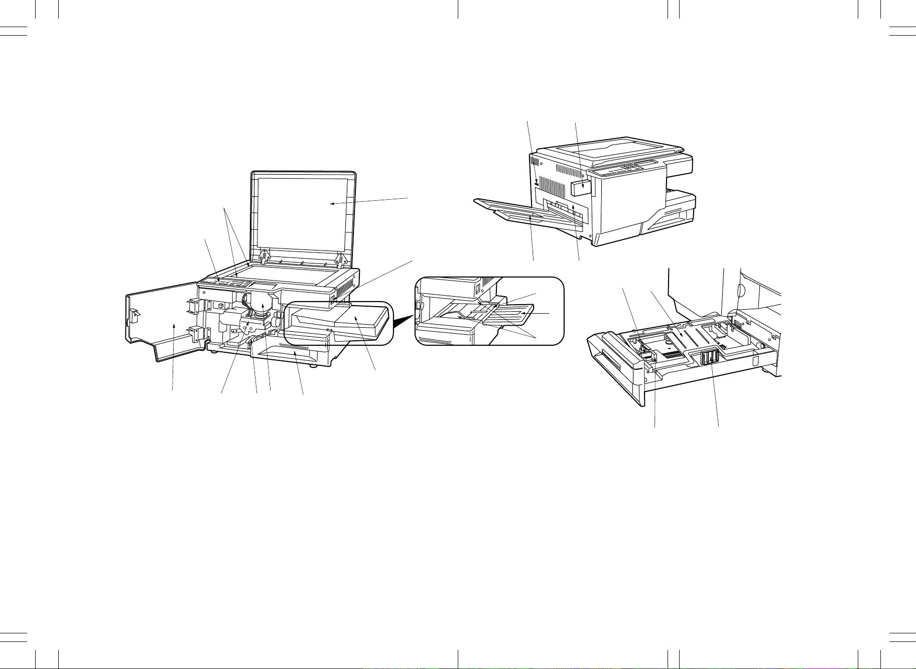
1-3-1 Part names and their functions
2
$
3
%
1
4
^&
5
(
*
6
7
#
@
E
!
1. Operation panel
2. Original size indicator
3. Original holder
4. Main switch
5. Bypass table
6. Auxiliary table
7. Insertion guides
0
9
8
Figure 1-3-1
8. Paper drawer
9. Toner cartridge
10. Paper conveying section lever
11. Image formation unit
12. Front cover
13. Bypass cover
14. Total counter
)
15. Key counter (option)
16. Copy tray
17. Eject cover
18. Drawer bottom plate
19. Width guide tab
20. Width guide
21. Length guide
⁄
1-3-1
E
A
E E
A A
EA
DC-2050 (MCE) S/M
A
Page 23
EE E
AA A
A
A
E
E
1AF
Metric
°
fl
^
‹
›
¤
&
*()
⁄
7
1
23
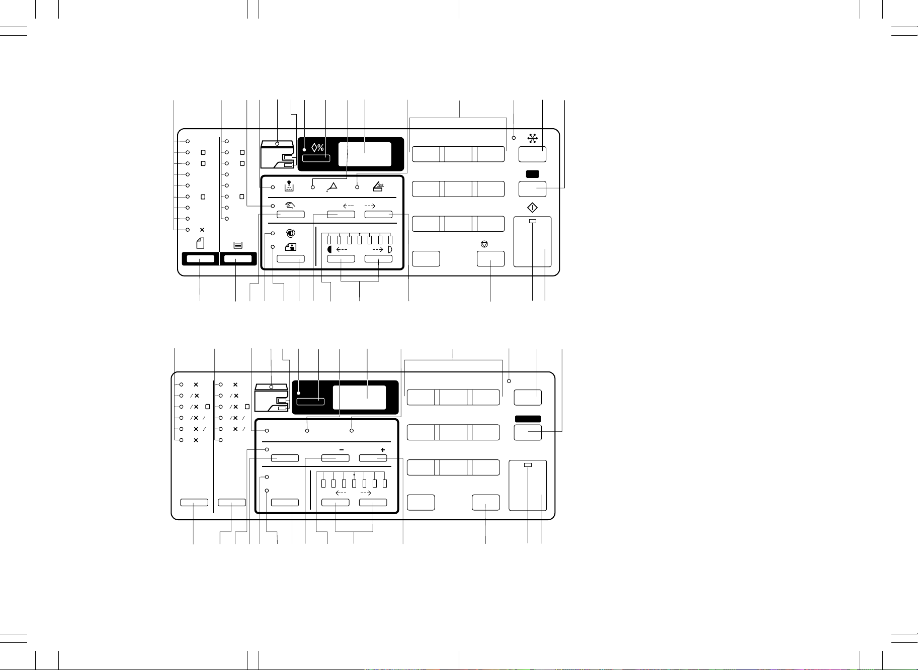
1. Auto selection key
2. Auto selection indicator
3. All clear/reset key
4. Print key
5. Copy start indicator
A3
R
A4
R
A5
A4
B4
R
B5
B5
Folio
11 15
A3
A4
A5
A4
B4
B5
Folio
U
12
R
141%
%
4
7
5
8
R
R
64%
34567
12
0
3
6. Stop/clear key
7. Numeric keys
C
6
A
8. Exposure adjustment keys
9. Exposure indicators
10. Auto/manual exposure key
9
11. Auto exposure indicator
12. Photo original indicator
13. Zoom-up key
/
C
14. Zoom-down key
15. Manual key
16. Manual indicator
17. Copy quantity/magnification display
18. Recall % key
19. Zoom copy indicator
20. Paper source indicators
21. Check paper size/direction indicator
22. Maintenance indicator
23. Add toner indicator
Inch
°
‡
fl
fi
%
‹
!
›
@#$
0
)
(
*
9
¤
8
&
⁄
7
6
2
5
1
4
3
24. ADF jam indicator
25. Paper select key
26. Paper size indicators
27. Original select key
28. Original size indicator
11 17
1
2
8 14
1
2
8 11
121
5 8
11
8
11 15
11 17
1
2
8 14
1
R R
2
8 11
121
2
5 8
1
2
11
U
Auto
Selection
Recall %
12
3
%
2
1
2
8
Add Toner
Manual
Maintenance
Zoom
( )
Check
Paper Size /
Direction
( )
Zoom
4
7
5
8
6
9
Reset
Print
Original
‡
fi
Paper
Select
Auto
Photo
Original
%^
0!@
$
Dark
9
Light
8
0
#
Stop/
Clear
6
5
4
Figure 1-3-2 Operation panel
1-3-2
E
A
EE E
AA A
DC-2050 (MCE) S/M
E
A
Page 24
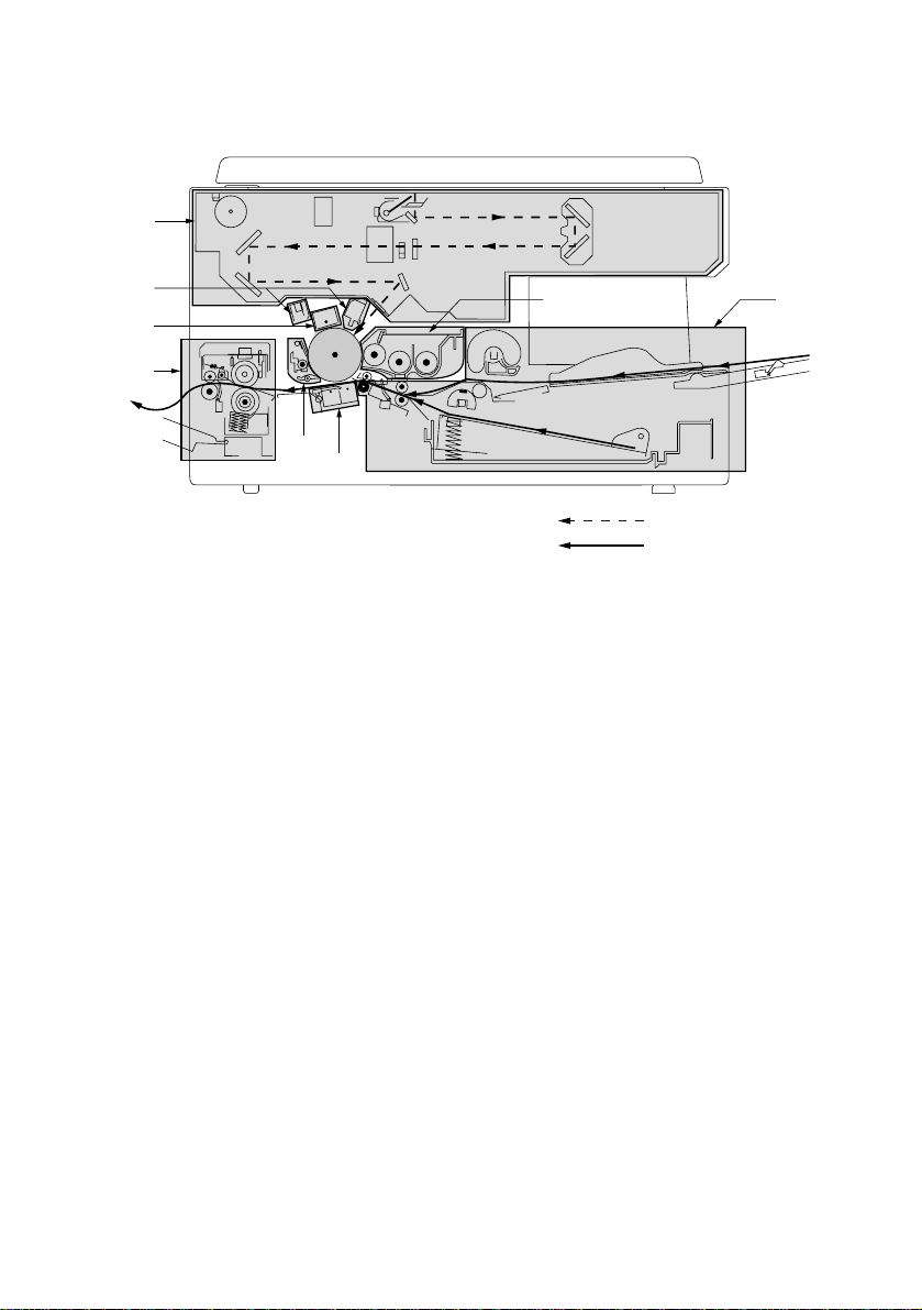
1-3-2 Machine cross section
3
1AF
7
2
8
4
6
5
Figure 1-3-3 Machine cross section
1. Paper feed section (page 1-3-6)
2. Main charging section (page 1-3-10)
3. Exposure section (page 1-3-15)
4. Developing section (page 1-3-21)
5. Transfer and separation section (page 1-3-31)
6. Cleaning section (page 1-3-34)
7. Charge erasing section (page 1-3-35)
8. Fixing and eject section (page 1-3-37)
1
Light path
Paper path
1-3-3
Page 25
1AF
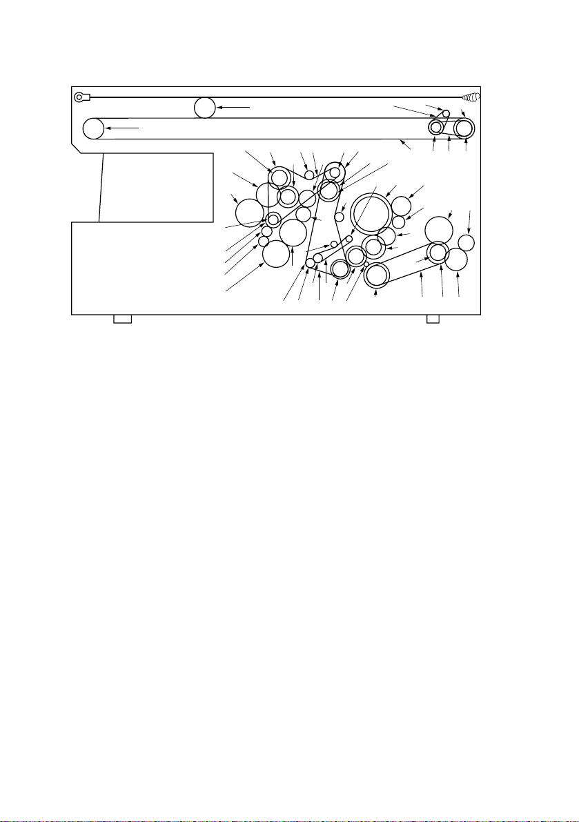
1-3-3 Drive system
Ú
¸
fi
fl
„
´
‰
ˇ
!
Figure 1-3-4 Drive system – copier main body
1. Drive motor gear
2. Gear 60/40
3. Gear 60/24
4. Gear 64/20
5. Gear 23
6. Gear 60/50
7. Blade thrust gear 31
8. Toner recycle gear 19
9. Developing drive belt
10. Pulley 16 (machine rear)
11. Gear 25 (machine front)
12. Registration gear 15/30
13. Feed belt
14. Registration collar
15. Pulley 15
16. Tension pulley 15
17. Gear 33/14 (machine rear)
18. Developing gear 32 (machine front)
19. Developing gear 23
20. Developing gear 30
21. Paper feed drive belt
22. Tension pulley 15
23. Pulley 32
24. Gear 18
25. Idle gear 38
26. Bypass gear 38
¤‹›
‡°
$
‚
&*
⁄
^
·
@#
90
123
As viewed from machine rear
27. Gear 30/18
28. Gear 25
29. Idle gear
30. Idle gear 38
31. Paper feed gear 38
32. Pulley 14
33. Gear 20
34. Retard gear 18
35. Limiter gear 15
36. Gear 80/34
37. Fixing drive belt
38. Pulley 30
39. Fixing drive gear 22
40. Heat roller gear 40
41. Eject idle gear 30
42. Eject gear 22
43. Scanner motor pulley
44. Scanner drive pulley 1
45. Scanner drive pulley 2
46. Scanner drive belt 1
47. Scanner drive belt 2
48. Scanner wire drum
49. Scanner wire
50. Scanner wire pulley
51. Scanner wire pulley
Ó
Ò
()
%
67
5
4
Ø
Á¨ˆ
Î
Ï˝
Ô
∏ŒÍ
8
Å
1-3-4
Page 26

1AF
67
Figure 1-3-5 Drive system – image formation unit
1. Blade thrust gear 31
2. Toner recycle gear 19
3. Magnet roller gear 17
4. Developing idle gear 19
14
235
As viewed from machine rear
5. Left spiral gear (machine rear)
6. Developing gear 28 (machine front)
7. Developing gear 31 (machine front)
1-3-5
Page 27
1AF
1-3-4 Mechanical construction
(1) Paper feed section
@%932
8
4
5
#
!
⁄
0
$
*7& ^6
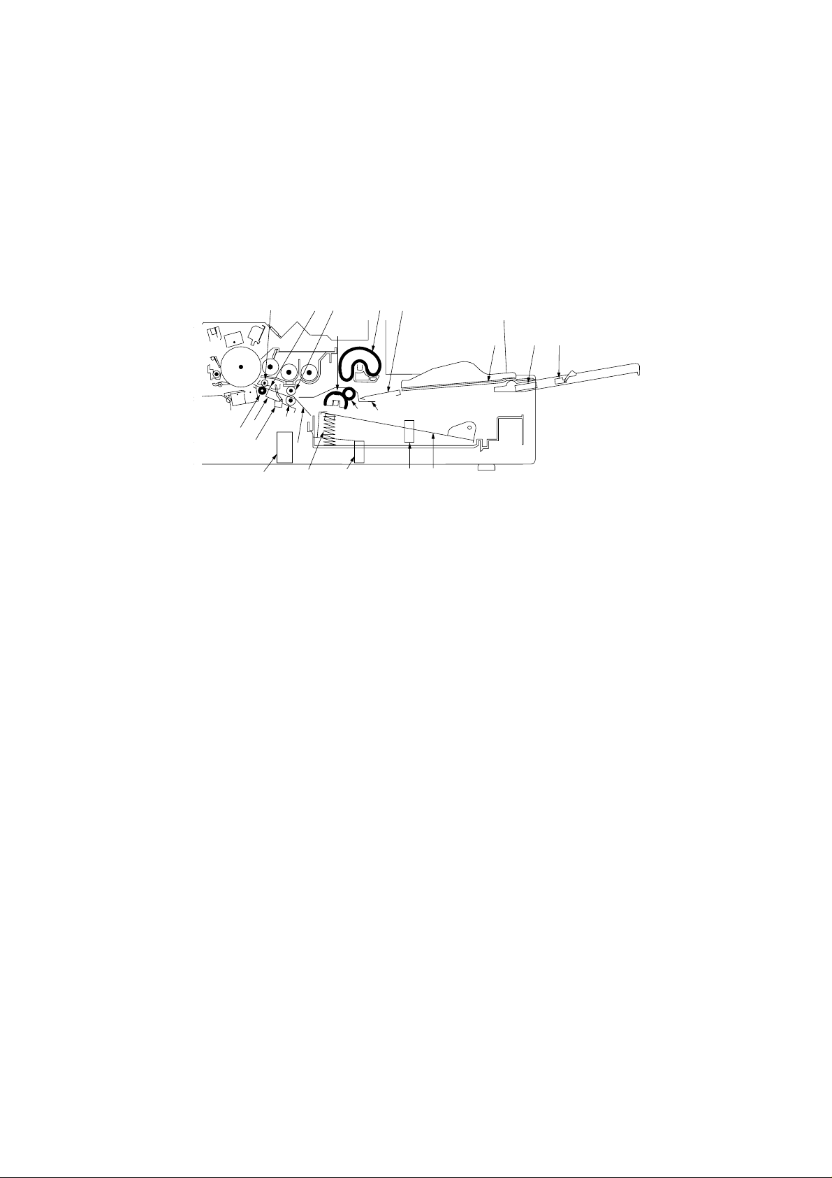
Figure 1-3-6 Paper feed section
1 Bypass table
2 Bypass lift
3 Bypass upper pulley
4 Bypass lower pulley
5 Bypass lower guide
6 Drawer bottom plate
7 Drawer spring
8 Paper feed pulleys A and B
9 Upper registration roller
0 Lower registration roller
! Registration stopper
1
)(
@ Upper pre-transfer roller
# Lower pre-transfer roller
$ Registration guide
% Upper pre-transfer guide
^ Bypass solenoid (BYPSOL)
& Paper feed solenoid (PFSOL)
* Registration solenoid (RSOL)
( Bypass paper length switch (BYPPLSW)
) Bypass paper width switch (BYPPWSW)
⁄ Registration switch (RSW)
1-3-6
DC-2050 (MCE) S/M
Page 28

1AF
The paper feed section consists of the primary feed and secondary feed subsections.
Primary feed conveys paper from the paper drawer or the bypass table to the upper and
lower registration rollers, at which point secondary paper feed takes place and the paper
travels to the transfer section in sync with the exposure timing.
CN12-2
CN17-2
CN2-2
CN2-4
CN14-2
MPCB
RSOL
RSW
PFSOL
Figure 1-3-7 Paper feed section block diagram
BYPPLSW
BYPSOL
1-3-7
DC-2050 (MCE) S/M
Page 29
1AF
(1-1) Paper feed from the paper drawer
The paper drawer consists of the drawer bottom plate, drawer springs and other components
and can hold up to 250 sheets of copy paper.
Paper is fed out of the drawer by the rotation of paper feed pulleys A and B.
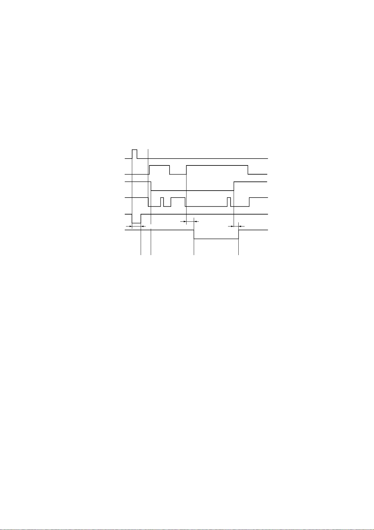
Prescan start
Print key
HPSW
RSW
SM
PFSOL
RSOL
250 ms
A
BC D
147 P+140 ms *
1
100 ms
Auto exposure mode, A4/11" × 81/2" copy paper, magnification ratio 100%
*1 Varies depending on the setting by simulation 27.
Timing chart 1-3-1 Paper feed from the paper drawer
A When the print key is pressed, the paper feed solenoid (PFSOL) turns on for 250 ms,
rotating paper feed pulleys A and B to perform primary feed. Then the paper is fed by
the upper and lower registration rollers and its leading edge stops at the registration
stopper to create slack in the paper before registration.
B The leading edge of the paper turns the registration switch (RSW) on.
C The scanner starts scanning and the home position switch (HPSW) turns off. After 147
pulses + 140 ms, the registration solenoid (RSOL) turns on and the registration stopper
lowers. The lower registration and pre-transfer rollers convey the paper to start
secondary feed.
D 100 ms after the trailing edge has turned the registration switch (RSW) off, the registration
solenoid (RSOL) turns off to complete secondary paper feed.
1-3-8
DC-2050 (MCE) S/M
Page 30
1AF
(1-2) Paper feed from the bypass table
The bypass table can hold up to 50 sheets of paper at one time.
When the print key is pressed, the bypass solenoid (BYPSOL) turns on, rotating the bypass
upper pulley, while the bypass lift is raised until the paper comes into contact with the bypass
upper pulley. The paper on the bypass table is then conveyed to the secondary paper feed
section.
The bypass lower pulley rotates opposite to the paper feed direction so that the torque limiter
prevents multiple sheets from being fed at one time.
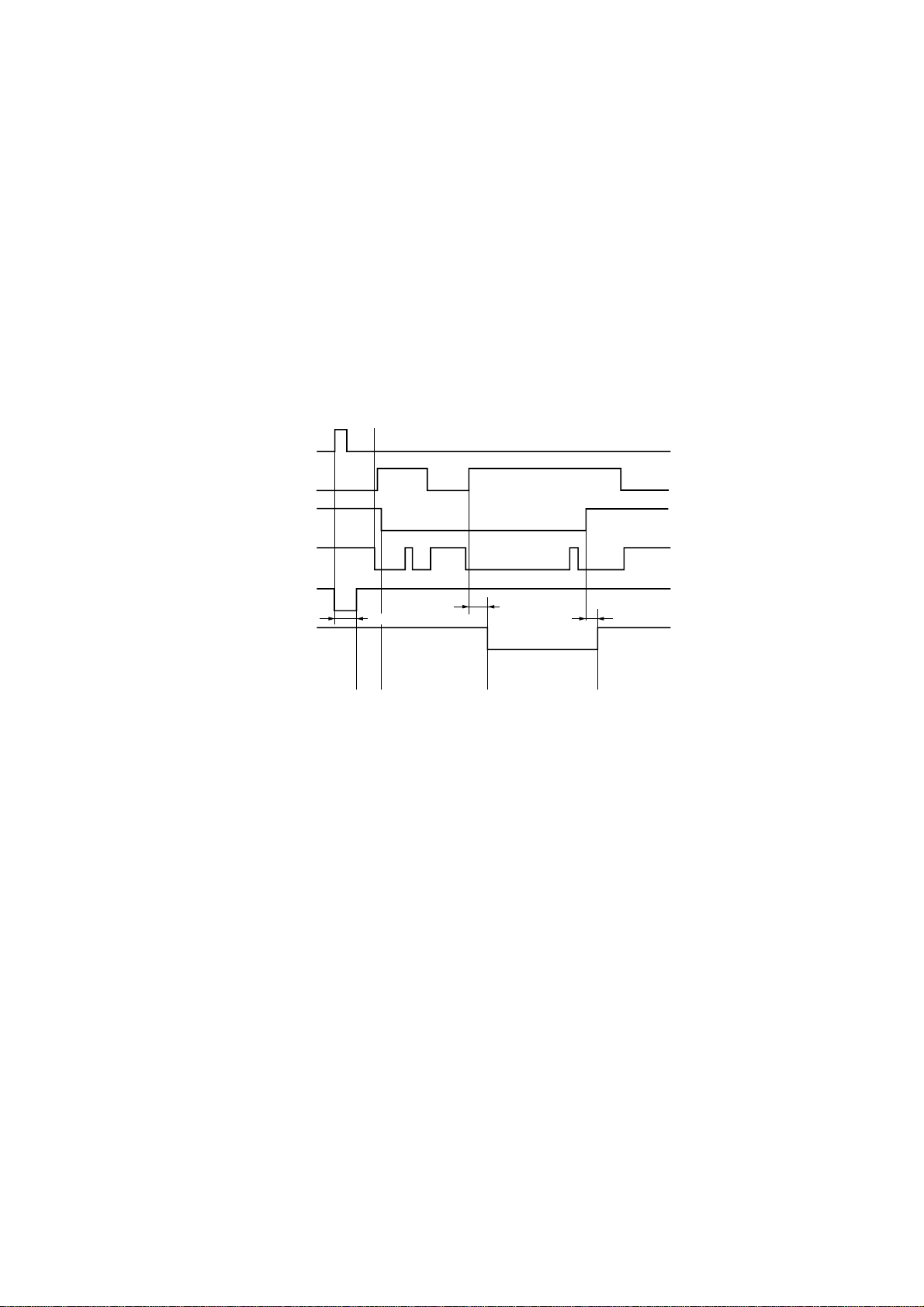
Prescan start
Print key
HPSW
RSW
SM
BYPSOL
RSOL
250 ms
A
BC D
147 P+140 ms *
1
100 ms
Auto exposure mode, A4/11" × 81/2" copy paper, magnification ratio 100%
*1 Varies depending on the setting by simulation 27.
Timing chart 1-3-2 Paper feed from the bypass table
A When the print key is pressed, the bypass solenoid (BYPSOL) turns on for 250 ms, which
raises the bypass lift and rotates the bypass lower pulley to perform primary paper feed.
The paper is then fed by the upper and lower registration rollers until the leading edge
stops at the registration stopper to create slack in the paper before registration.
B The leading edge of the paper turns the registration switch (RSW) on.
C The scanner starts scanning and the home position switch (HPSW) turns off. After 147
pulses + 140 ms, the registration solenoid (RSOL) turns on and the registration stopper
lowers. The lower registration and pre-transfer rollers convey the paper to start
secondary feed.
D 100 ms after the trailing edge of the paper turns the registration switch (RSW) off, the
registration solenoid (RSOL) turns off to complete secondary paper feed.
1-3-9
DC-2050 (MCE) S/M
Page 31

1AF
(2) Main charging section
The main charging section consists of the drum and main charger. The drum is electrically
charged uniformly by means of a grid to form a latent image on the surface.
Main charger
Tungsten wire
Main charger grid
Figure 1-3-8 Main charging section
1-3-10
DC-2050 (MCE) S/M
Page 32

5
1AF
8
9
7
!
6
Figure 1-3-9 Main charger
1 Main charger front housing
2 Main charger rear housing
3 Main charger shield
4 Tungsten wire
5 Main charger grid
6 Grid tension plate
CN2-1
CPCB
CN1-21
CN1-27
CN1-24
CN1-20
MPCB
24 V DC
MC REM
ALARM
GRID CONT
DB REM
4
@
3
1
7 Main charger front lid
8 Main charger rear lid
9 Charger spring
0 Charger terminal
! Charger wire retainer pin
@ Film
CN2-1
CN1-7
CN1-1
CN1-4
CN1-8
HVTPCB
0
2
MC
Grid
Drum
Figure 1-3-10 Main charging section block diagram
DC-2050 (MCE) S/M
1-3-11
Page 33

1AF
Scanner return start
Print key
SM
BL
MC REM
300 ms
All on
Forward Reverse
50 ms
AB C
Timing chart 1-3-3 Main charging
A 300 ms after the print key is pressed, all the blank lamps (BL) turn on.
B 50 ms after the all blank lamps (BL) have turned on, main charging starts.
C As soon as the scanner starts to return, main charging ends.
1-3-12
DC-2050 (MCE) S/M
Page 34

1AF
Surface potential correction control
The drum surface potential is corrected for the external temperature and humidity. If the
external temperature is 24°C/75.2°F or less and the absolute humidity exceeds 25.0 g/m3,
the drum surface potential is corrected as in the table bellow. The external temperature and
relative humidity are detected by the external temperature thermistor (ETTH) and humidity
sensor (HUMSENS) and the absolute humidity is calculated from these values. The surface
potential is corrected by varying the grid control voltage (GRID CONT) output from the main
PCB (MPCB) to the high-voltage transformer PCB (HVTPCB).
Table 1-3-1 Surface potential correction value vs. absolute humidity
Absolute
humidity
(g/m3)
0.0
0.5
1.0
1.5
2.0
2.5
3.0
3.5
4.0
4.5
5.0
5.5
6.0
6.5
7.0
7.5
8.0
8.5
9.0
9.5
10.0
Correction
value
(V)
0
0
0
0
0
0
0
0
0
0
0
0
0
0
0
0
0
0
0
0
0
Absolute
humidity
(g/m3)
10.5
11.0
11.5
12.0
12.5
13.0
13.5
14.0
14.5
15.0
15.5
16.0
16.5
17.0
17.5
18.0
18.5
19.0
19.5
20.0
Correction
value
(V)
0
0
0
0
0
0
0
0
0
0
0
0
0
0
0
0
0
0
0
0
Absolute
humidity
(g/m3)
20.5
21.0
21.5
22.0
22.5
23.0
23.5
24.0
24.5
25.0
25.5
26.0
26.5
27.0
27.5
28.0
28.5
29.0
29.5
30.0
Correction
value
(V)
0
0
0
0
0
0
0
0
0
0
–4
–8
–12
–16
–20
–24
–28
–32
–36
–40
1-3-13
DC-2050 (MCE) S/M
Page 35

1AF
45
40
35
)
3
30
100%
80%
25
20
15
Absolute humidity (g/m
10
5
0
10
50
15
59
20
68
Temperature (°C/°F)
25
77
30
86
Figure1-3-11 Absolute humidity vs. relative humidity
Table 1-3-2 Surface potential correction value vs. external temperature
Temperature
(°C/°F)
1/33.8
2/35.6
3/37.4
4/39.2
6/42.8
7/44.6
8/46.4
9/48.2
10/50
11/51.8
12/53.6
0/32
5/41
Correction
value (V)
Temperature
83
80
77
73
70
67
63
60
57
53
50
47
43
(°C/°F)
13/55.4
14/57.2
15/59
16/60.8
17/62.6
18/64.4
19/66.2
20/68
21/69.8
22/71.8
23/73.4
24/75.2
25/77
Correction
value (V)
Temperature
40
37
33
30
27
23
20
17
13
10
7
3
0
(°C/°F)
26/78.8
27/80.6
28/82.4
29/84.2
30/86
60%
40%
20%
(°C)
35
(°F)
95
Correction
value (V)
Relative humidity (%)
0
0
0
0
0
1-3-14
DC-2050 (MCE) S/M
Page 36

(3) Exposure section
1AF
& $4 % 987@#
5
6
(
Figure 1-3-12 Exposure section
1 Mirror 1
2 Mirror 2
3 Mirror 3
4 Mirror 4
5 Mirror 5
6 Mirror 6
7 Halogen lamp (HL)
8 Optical section thermostat (TH3)
9 Lens
0 Light source unit 1
! Light source unit 2
@ Main reflector
# Auxiliary reflector
$ Scanner motor (SM)
% Optical section fan motor (OPFM)
^ AE sensor (AES)
& Home position switch (HPSW)
* Lens home position switch (LHPSW)
( Dust filter
32 !
1
0
^
*
1-3-15
DC-2050 (MCE) S/M
Page 37

1AF
This copier employs a slit exposure system with a fixed original table, and a halogen lamp
(HL) as the light source.
The optical section consists of light source units 1 and 2. Light source unit 1 carries the
halogen lamp and the main and auxiliary reflectors. Each unit travels from one side of the
machine to the other along scanner rails at machine front and rear. When an enlargement
or a reduction ratio is selected, the scanning speeds of the two light source units and the
positions of the lens and mirrors 4 and 5 are changed, altering the distance between the
original and the drum. At any magnification ratio, light source unit 2 travels at a half speed
of unit 1.
A cooling fan is installed to exhaust heat generated by the halogen lamp. If an abnormally
high temperature is detected around light source unit 1, the optical section thermostat (TH3)
shuts off the supply to the halogen lamp.
Original
HPSW AES
SM
CN8-1 –
CN8-6
CN7-2
HL
CN5-5
LM
CN5-7 –
TH3
CN5-12
MPCB
Figure 1-3-13 Exposure section block diagram
LHP
SW
CPCB
CN1-1
CN1-3
CN2-7CN4-5
HL CONT
CN5-2
1-3-16
DC-2050 (MCE) S/M
Page 38

1AF
Scan start
Scanner return start
10 P
480 ms
1687 P
Forward Reverse
G
Print key
HPSW
SM
HL
Prescan start
10 P
480 ms
1232 P
Forward
Reverse
AB FECD
Auto exposure mode, A4/11" × 81/2" original
Timing chart 1-3-4 Scanner travel
A When the print key is pressed, the halogen lamp (HL) lights at the intensity for prescan.
B 480 ms after the halogen lamp (HL) has turned on, the scanner motor (SM) rotates
forward for prescan.
C After rotating forward 1232 pulses, the scanner motor (SM) reverses to return the
scanner to the home position. At the same time, the halogen lamp (HL) turns off.
D 10 pulses after the home position switch (HPSW) has been turned on, the scanner motor
(SM) turns off and the scanner stops. At the same time, the halogen lamp (HL) lights for
exposure.
E 480 ms after turning off, the scanner motor (SM) rotates forward for scanning.
F After rotating forward for 1687 pulses, the scanner motor (SM) reverses to return the
scanner to the home position. At the same time, the halogen lamp (HL) turns off.
G 10 pulses after the home position switch (HPSW) has turned on, the scanner motor (SM)
turns off and the scanner stops.
1-3-17
DC-2050 (MCE) S/M
Page 39

1AF
Exposure control for manual exposure and photo modes
The halogen lamp light intensity for manual exposure and photo modes is calculated from
the data obtained by running simulation 24.
Light intensity value
Manual exposure mode
Photo mode
Drum potential 850 V DC
Drum potential
680 V DC
Drum potential
680 V DC
0
1-2
1-3
1-4
1-5
1-6
1-7
23456
1
7 7-1
7-2 7-3 7-4 7-5
Exposure scale (Exp.)
7-6
Figure 1-3-14 Exposure gradient setting
• Exposure control for manual exposure mode
The gradient between Exp. 1-2 and Exp. 7 is determined from the halogen lamp light
intensity values for Exp. 1, Exp. 4 and Exp. 7 set in simulation 24. For exposure settings Exp.
7-1 and above the drum potential is set 170 V below the normal level and the light intensity
is reduced since the intensity at such high exposure levels cannot be increased by simply
increasing the halogen lamp control voltage. The amount of exposure for the high settings
between Exp. 7-1 and Exp. 7-6 is determined by the halogen lamp light intensity value for
Exp. 7-1 set in simulation 24 and the gradient between Exp. 4 and Exp. 7.
• Exposure control for photo mode
The drum potential is set 170 V below the normal level and the halogen lamp light intensity
value is set low for photo mode.
The halogen lamp light intensity value for photo-mode Exp. 4 is determined by running
simulation 24. The light intensity for manual-mode Exp. 1-4 is used as the value for photomode Exp. 1, which determines the gradient between Exp. 1 and Exp. 4 for photo mode.
Similarly, the light intensity for manual-mode Exp. 7-3 is used as the value for photo-mode
Exp. 7, which determines the gradient between photo-mode Exp. 4 and Exp. 7.
1-3-18
DC-2050 (MCE) S/M
Page 40

1AF
Exposure control for auto exposure mode
In auto exposure mode, the halogen lamp lights at the intensity set for mode 1 in simulation
22 to perform prescan. The exposure level to copy that particular original is determined by
using the value read in by the AE sensor.
Scanner
movement
Original leading edge
AE detection (prescan)
Exposure
Original
Figure 1-3-15 AE sensor detection width
Halogen lamp voltage
Drum potential 680 V DC
0
Manual-mode Exp. 7-1
Mode 3, sim. 22
(NPTC level)
AE sensor read-in value
Drum potential 850 V DC
Mode 2, sim. 22
(NTC level)
Original leading edge
148 mm
100 mm
Detection width
Manual-mode Exp. 4
Figure 1-3-16 Exposure control for auto exposure mode
The halogen lamp voltage is controlled so that the lamp lights at the intensity for manualmode Exp. 4 when the AE sensor read-in value is the NTC level set in mode 2 by simulation
22, and at the intensity for manual-mode Exp. 7-1 when the read-in value is the NPTC level
set in mode 3.
In auto exposure mode, the drum potential is decreased by 170 V from the normal level and
the halogen lamp voltage is increased when the AE sensor read-in value is below the setting
for mode 3 in simulation 22. When the AE sensor read-in value falls in the range between
the mode 3 and mode 2 settings by simulation 22, the halogen lamp voltage is controlled
based on the gradient determined by the values set by simulation 24. For read-in values
above the mode 2 setting of simulation 22, the halogen lamp voltage is kept at a constant
level so that the lamp lights at the intensity for manual-mode Exp. 4.
1-3-19
DC-2050 (MCE) S/M
Page 41

1AF
Light intensity correction for enlargement and reduction modes
The halogen lamp light intensity for enlargement and reduction modes is determined by the
value for copying at 100% magnification and the correction values set by simulation 29.
Light intensity correction value
Mode 1, sim. 29
(141%)
Mode 2, sim. 29
(64%)
0
64 100 141
Magnification
ratio (%)
Figure 1-3-17 Correction of light intensity for reduction and enlargement modes
The correction values for reduction (64%) and enlargement (141%) copying are linked by
a straight line through the value for 100% magnification, and the light intensity is corrected
for individual magnification ratios according to the gradients.
Light intensity correction by the user setting
The light intensity data can be corrected in exposure adjustment of the user settings by
pressing an exposure adjustment key in manual exposure mode or the auto/manual
exposure key in auto exposure mode for 5 s. The light intensity correction value is 0 at Exp.
4 and changes at 4 bits per 0.5 steps of the exposure scale.
Light intensity correction value (bits)
18
0
4 bits
–18
0.5 steps
14 7
Exposure scale (Exp.)
Figure 1-3-18 Light intensity correction by user setting
1-3-20
DC-2050 (MCE) S/M
Page 42

1AF
(4) Developing section
The developing section consists of the developing assembly and toner hopper.
Developing
assembly
Figure 1-3-19 Developing section
The developing assembly consists of the developing roller where a magnetic brush is
formed, doctor blade and the developing spirals that agitate the developer.
In the toner hopper new toner from the toner cartridge is mixed with residual toner recovered
from the cleaning section, and the mixture is conveyed to the developing assembly.
The amount of toner in the toner hopper is monitored by the toner level sensor (TLDS).
1-3-21
DC-2050 (MCE) S/M
Page 43

1AF
Toner hopper
Cleaning assembly
Cleaning spiral
Hopper paddle A
Hopper spiral
Developing assembly
Right developing spiral
Left developing spiral
Toner level sensor
Toner feed motor
Hopper paddle B
Toner flow
Figure 1-3-20 Toner recycling
1-3-22
DC-2050 (MCE) S/M
Page 44

1AF
Formation of the magnetic brush
The developing roller consists of a magnet roller with five poles and a sleeve roller. Rotation
of the sleeve roller around the magnet roller entrains developer, which in turn forms a
magnetic brush at pole N1 on the magnet roller. The height of the magnetic brush is
regulated by the doctor blade; the developing result is affected by the positions of the poles
on the magnet roller and the position of the doctor blade.
A developing bias voltage generated by the high-voltage transformer PCB (HVTPCB) is
applied to the developing roller to provide image contrast.
Magnetic poles on the magnet roller
654
A
70°
S1
70°
N2
2
A: distance between the doctor blade and
developing roller: 0.6 ± 0.05 mm
Figure 1-3-21 Forming the magnetic brush
1 Developing unit housing
2 Developing roller
3 Toner sensor (TNS)
13
4 Doctor blade
5 Right developing spiral
6 Left developing spiral
N1
N1: 850 × 10
N2: 600 × 10
S1: 600 × 10
S2: 600 × 10
S3: 500 × 10
S2
–4
± 50 × 10–4T
–4
± 50 × 10–4T
–4
± 50 ×10–4T
–4
± 50 ×10–4T
–4
± 50 ×10–4T
60°
S3
70°
1-3-23
DC-2050 (MCE) S/M
Page 45

1AF
CN11-5
CN11-6
MPCB
CN11-9
CN11-10
CN11-3
CN11-1
CN1-20
TNS SIG
TNS CONT
DB REM
TLDS
TNS
CN1-8
HVTPCB
TFM
Developing bias
Figure 1-3-22 Developing unit block diagram
Toner density is detected by the toner sensor (TNS).
The sensor section of the toner sensor detects the ratio of toner to carrier in the developer
near it and converts it into a voltage. As more toner is used, the ratio of toner to carrier
decreases, increasing the toner sensor output voltage.
When the ratio drops below the specified value, the increase in toner sensor output voltage
triggers toner replenishing. When toner is added and the ratio of toner to carrier returns to
normal, the toner sensor output voltage drops to the point where toner replenishing stops.
1-3-24
DC-2050 (MCE) S/M
Page 46

1AF
Toner density control
Toner density is controlled by switching the toner feed motor on/off using as the reference
the toner sensor output based on the toner sensor initial output value set when simulation
60 was executed when the developer was set. The toner sensor output is also used for toner
empty detection in the toner hopper. On this device, a magnetic proximity sensor toner level
sensor (TLDS) is also used, but the toner remaining amount is not detected until the toner
empty state is detected from the toner sensor output voltage.
When no toner is detected by
the TLDS, the add toner
Toner sensor
output voltage (V)
AP detection level
(3.56)
Toner empty end
level (3.21)
Toner feed motor
on level (2.72)
Toner feed motor
off level (2.70)
“AP” blinks on the
copy quantity display.
indicator lights here.
max. 3 min.
max. 3 min.
Forced toner
feed
If the level does not go down even
after the additional forced toner
feed, the add toner indicator
lights here.
Intermittent feed (3
minutes max.) until the
toner feed motor off
level is reached.
Copy operation
AB C D E
Forced feed (continuous operation)
Intermittent feed (1 s on/0.5 s off)
Figure 1-3-23
A When the toner sensor output voltage exceeds the toner feed motor on level, the toner
feed motor intermittent feed (1 s on, 0.5 s off) operation is carried out to feed the toner.
B When the toner is fed and the toner sensor output voltage falls below the toner feed motor
off level, the intermittent feed operation is stopped.
C When the toner in the toner hopper runs low and, even though the toner intermittent feed
operation is continued, the toner sensor output voltage rises above the AP detection
level, “AP” blinks on the copy quantity display and the toner feed motor forced feed
(continuously on) operation starts. At the same time, the amount of toner remaining is
detected by the toner level sensor.
1-3-25
DC-2050 (MCE) S/M
Page 47

1AF
D If the toner sensor output voltage falls to the toner empty end level within the toner feed
motor forced feed operation time (3 minutes max.), the copier returns to the ready state
and intermittent feed operations (3 minutes max.) are carried out until the toner sensor
output voltage drops to the toner feed motor off level. If the toner sensor output voltage
does not fall to the toner empty end level within the forced feed operation time, the
following operations are carried out according to the state of the toner level sensor.
A: When the toner level sensor detects that there is no toner remaining.
After the forced feed operation time ends, the add toner indicator lights.
B: When the toner level sensor does not detect that there is no toner remaining.
The forced feed operation is continued for an extra period of no more than three
minutes.
E If the toner sensor output voltage does not return to the toner empty end level within the
additional forced feed operation time, after the end of the additional forced feed
operation time, the add toner indicator lights.
If the toner sensor output voltage falls to the toner empty end level within the additional
forced feed operation time, the copier retums to the ready state and intermittent feed
operations (3 minutes max.) are carried out until the toner sensor output voltage drops
to the toner feed motor off level.
Toner sensor output
voltage (V)
AP detection level
Toner empty end
Toner feed motor
Toner feed motor
(3.56)
level (3.21)
on level (2.72)
off level (2.70)
Toner cartridge replacement
6 min. max.
Forced toner feed
If forced feed does not lower
the level, the add toner
indicator stays lit.
The add toner indicator turns
off and intermittent feed
continues (3 minutes max.)
until the toner feed motor
off level is reached.
Copy operation
GF
Figure 1-3-24
F After the toner cartridge is replaced, the forced feed operation (6 minutes max.) is started
by turning safety switch 1 off/on. During the forced feed operation time, the toner is fed
and when the toner sensor output voltage reaches the toner empty end level, the “AP”
goes out and the copier goes into the ready state. Further intermittent feed operations
(3 minutes max.) are carried out until the toner sensor output voltage reaches the toner
feed motor off level.
G If the toner sensor output voltage does not reach the toner empty end level within the
forced feed operation time, the add toner indicator stays lit even after the end of the
forced feed operation time.
1-3-26
DC-2050 (MCE) S/M
Page 48

II
ELECTRICAL
SECTION
II Electrical Section
DC-2050 (MCE) S/M
Page 49

CONTENTS
2-1 Electrical Parts Layout
2-1-1 Electrical parts layout.......................................................................... 2-1-1
1AF
1-1-11
Page 50

1AF
1-1-12
Page 51

2-1-1 Electrical parts layout
1AF
5
3
Machine front Machine inside Machine rear
1
2
4
Figure 2-1-1 Layout of electrical parts: PCBs
1. Main PCB (MPCB) ............................................. Controls the other PCBs and
electrical components.
2. Composite PCB (CPCB) .................................... Contains safety switch 1 and
noise filter; generates 24 V and
5V DC; and controls the halogen
lamp and fixing heater.
3. High-voltage transformer PCB (HVTPCB) ......... Performs main charging;
generates developing bias and
high voltage for transfer and
separation charging.
4. Humidity sensor PCB (HUMPCB)...................... Detects absolute humidity.
5. Operation unit PCB (OPCB) .............................. Consists of operation keys and
display LEDs.
2-1-1
Page 52

1AF
11
12 10
2
18
14
13
3
17
9
Machine front Machine inside Machine rear
16
15
8
4
19
1
20
5
7
6
Figure 2-1-2 Layout of electrical parts: switches and sensors
1. Main switch (MSW) ............................................ Turns the AC power on and off.
2. Safety switch 1 (SSW1) ..................................... Breaks the safety circuit when the
front cover is opened, and resets
paper jam detection.
3. Safety switch 2 (SSW2) ..................................... Breaks the safety circuit when the
eject cover is opened, and resets
paper jam detection.
4. Drawer switch (CASDSW) ................................. Detects the presence or absence
of the paper drawer.
5. Bypass paper length switch (BYPPLSW) .......... Detects the length of paper on the
bypass table.
6. Bypass paper width switch (BYPPWSW) .......... Detects the width of paper on the
bypass table.
7. Bypass table extended detection switch
(BYPEDSW) ...................................................... Detects when the bypass table is
extended to use long paper.
8. Registration switch (RSW) ................................. Controls the secondary paper
feed start timing.
9. Eject switch (ESW) ............................................ Detects a paper jam in the fixing
section.
10. AE sensor (AES)................................................ Detects the original density.
11. Home position switch (HPSW)........................... Detects the scanner in the home
position.
12. Lens home position switch (LHPSW) ................ Detects the lens in the home
position.
13. Toner cartridge detection switch 1
(TCDSW1) ......................................................... Detects the presence or absence
of the toner cartridge.
2-1-2
Page 53

1AF
14. Toner cartridge detection switch 2
(TCDSW2) ......................................................... Detects the presence or absence
of the toner cartridge.
15. Toner sensor (TNS) ........................................... Detects the toner density in the
developing unit.
16. Toner level sensor (TLDS)................................. Detects the toner level in the toner
hopper.
17. Fixing unit thermistor (FTH) ............................... Detects the heat roller
temperature.
18. Drum thermistor (DTH) ...................................... Detects the drum section
temperature.
19. Humidity sensor (HUMSENS)............................ Detects the external humidity.
20. External temperature thermistor (ETTH) ........... Detects the external temperature.
2-1-3
Page 54

1AF
2
6
7
5
3
4
1
10
Machine front Machine inside Machine rear
9
8
Figure 2-1-3 Layout of electrical parts: motors and solenoids
1. Drive motor (DM) ............................................... Drives the machine.
2. Scanner motor (SM) .......................................... Drives the optical system.
3. Lens motor (LM) ................................................ Drives the lens and mirrors 4 & 5.
4. Toner feed motor (TFM) .................................... Replenishes toner.
5. Optical section fan motor (OPFM) ..................... Cools the optical section.
6. Internal cooling fan motor (ICFM) ...................... Cools the machine interior.
7. Ozone exhaust fan motor (OEFM)..................... Exhausts ozone.
8. Paper feed solenoid (PFSOL)............................ Primary paper feed from the
paper drawer.
9. Bypass solenoid (BYPSOL)............................... Performs primary paper feed from
the bypass table, and operates
the bypass lift.
10. Registration solenoid (RSOL) ............................ Operates the registration stopper.
2-1-4
Page 55

7 9
1
1AF
8
5,6
4
Machine front Machine inside Machine rear
3
2
Figure 2-1-4 Layout of electrical parts: other electrical parts
1. Halogen lamp (HL)............................................. Performs exposure.
2. Cleaning lamp (CL) ............................................ Removes residual charge from
the drum surface.
3. Blank lamps (BL) ............................................... Remove charge from non-image
forming areas of the drum
surface.
4. Fixing heater (H) ................................................ Heats the heat roller.
5. Fixing unit thermostat 1 (TH1) ........................... Prevents overheating in the fixing
section.
6. Fixing unit thermostat 2 (TH2) ........................... Prevents overheating in the fixing
section.
7. Optical section thermostat (TH3) ....................... Prevents overheating in the
optical system.
8. Total counter (TC).............................................. Displays the total number of
copies produced.
9. *Solid state relay (SSR) ..................................... Controls the fixing heater.
* For 230 V specifications only.
2-1-5
Page 56

CONTENTS
2-2 Detection of Paper Misfeed
2-2-1 Paper misfeed detection ..................................................................... 2-2-1
2-2-2 Paper misfeed detection conditions .................................................... 2-2-2
1AF
1-1-13
Page 57

1AF
1-1-14
Page 58

1AF
2-2-1 Paper misfeed detection
When a paper jam occurs, the copier immediately stops copying and the copy quantity/
magnification display on the operation unit shows PF, J30, J40 or J50 indicating the location
of the jam.
Paper jam counts sorted by the detecting conditions can be checked by jam code in
simulation 74.
To remove paper jammed in the copier, open the drawer, open the front cover and operate
the paper conveying section lever, open the eject cover, or open the eject cover and detach
the fixing unit guide.
To reset the paper misfeed detection, open and close the front or eject cover to turn safety
switch 1 or 2 off and on.
Metric
• %
Inch
• Recall %
PF: no paper feed (or, no paper present in the drawer)
J30: paper jam in the registration section
J40: paper jam in the paper conveying or fixing section
J50: paper jam in the eject section
Figure 2-2-1 Misfeed location indication
ESW RSW
RSOL PFSOL
Figure 2-2-2 Misfeed detection
BYPSOL
2-2-1
Page 59

1AF
2-2-2 Paper misfeed detection conditions
No paper feed (PF)
• The registration switch (RSW) does not turn on within 1500 ms after the paper feed
solenoid (PFSOL) has turned on during drawer paper feed.
PFSOL
RSW
1500 ms
Off
On
Off
On
Timing chart 2-2-1
• The registration switch (RSW) does not turn on within 2500 ms after the bypass
solenoid (BYPSOL) has turned on during bypass paper feed.
BYPSOL
RSW
2500 ms
Off
On
Off
On
Timing chart 2-2-2
Paper jam in the registration section (J30)
• The registration switch (RSW) is on when the main switch is turned on or when the
front or eject cover is closed.
• The registration switch (RSW) does not turn off within 3580 ms after the registration
solenoid (RSOL) has turned on.
RSOL
RSW
3580 ms
Off
On
Off
On
Timing chart 2-2-3
2-2-2
Page 60

1AF
Paper jam in the paper conveying or fixing section (J40)
• The eject switch (ESW) does not turn on within 1650 ms after the registration solenoid
(RSOL) has turned on [except for the 1200 ms from the registration switch (RSW)
turning off when the drive does not stop].
RSOL
ESW
1650 ms
Off
On
Off
On
Timing chart 2-2-4
Paper jam in the eject section (J50)
• When the eject switch (ESW) is on when the main switch is turned on or when the
front or eject cover is closed, a forced-ejection is performed; the eject switch (ESW)
does not turn off within 2800 ms.
ESW
2800 ms
Off
On
Timing chart 2-2-5
• The eject switch (ESW) does not turn off within 3580 ms after the eject switch (ESW)
has turned on.
ESW
3580 ms
Off
On
Timing chart 2-2-6
2-2-3
Page 61

CONTENTS
2-3 Operation of the PCBs
2-3-1 Composite PCB .................................................................................. 2-3-1
2-3-2 Main PCB............................................................................................ 2-3-3
(1) Fixing unit abnormally high temperature/shorted thermistor detection
circuit.................................................................................................... 2-3-4
(2) Toner feed motor drive circuit .............................................................. 2-3-5
(3) Scanner motor drive circuit .................................................................. 2-3-6
(4) Reset circuit ......................................................................................... 2-3-7
2-3-3 Operation unit PCB .............................................................................. 2-3-8
1AF
1-1-15
Page 62

1AF
1-1-16
Page 63

2-3-1 Composite PCB
1AF
AC
input
H
HL
HL CONT
H REM
Noise
filter
circuit
section
L1
TH
602
TH
601
PC3
MSW
SSW1
PT2
PWM
signal/
voltage
converter
circuit
Q602
PT1
PC4
AVR circuit section
Halogen
lamp
light
intensity
control
IC
(HIC)
DH
Noise
filter
circuit
L001
Power source
circuit section
Rectifying
circuit
D001
24 V DC
smoothing/
output
circuit
D201/
C201/
C207
CPCB
Switching
circuit IC1
Figure 2-3-1 Composite PCB block diagram
C101
Q101
PC1 PC2
Output
feedback
circuit
5 V DC
smoothing/
output
circuit
IC3
TRNS
24 V DC
output
5 V DC
output
The composite PCB (CPCB) consists of three circuit sections: noise filter, power source and
AVR.
• Noise filter circuit section
The noise filter circuit consists of choke coil L1, a resistor and capacitor. These attenuate
external noise and prevent noise generated by the composite PCB (CPCB) and other
electrical components from escaping out of the copier via the AC line.
• Power source circuit section
The power source circuit section is a switching regulator which converts the AC input into
5 V and 24 V DC outputs. This section consists of the noise filter circuit, rectifying circuit,
switching circuit, 24 V DC smoothing/output circuit, 5 V DC smoothing/output circuit and
output feedback circuit.
The noise filter circuit consists of choke coil L001 and a capacitor. Any external noise that
has passed through the preceding noise filter circuit section is attenuated here, while the
switching noise generated in this section is prevented from escaping out via the AC line. The
AC input is full-wave rectified by diode bridge D001 and then smoothed by smoothing
2-3-1
Page 64

1AF
capacitor C101 in the rectifying circuit. The switching circuit turns FET Q101 on and off via
switching control IC1, turning current to the primary coil of switching transformer TRNS on
and off. The 24 V DC smoothing/output circuit converts the current induced in the secondary
coil of TRNS into a stable 24 V DC output via diode D201 and smoothing capacitors C201
and C207. The 5 V DC smoothing/output circuit converts the 24 V DC output from the 24
V DC smoothing/output circuit into a stable 5 V DC using regulator IC3. Switching control
IC1 regulates the 24 V DC supply by controlling the switching operation of FET Q101
depending on the signal fed back by the output feedback circuit via photocoupler PC1. If an
overvoltage occurs on the 24 V or 5 V DC output, the output feedback circuit sends that
information to switching control IC1 via photocoupler PC2, inhibiting IC1.
• AVR circuit section
The AVR circuit section consists of the PWM signal/voltage converter circuit, a halogen
lamp control subsection with the halogen lamp light intensity control IC (HIC), and a
switching subsection with thyristors TH601 and TH602 that turn the fixing heater (H) and
halogen lamp (HL) on and off.
Control signal H REM from the main PCB turns photocoupler PC4 on when low. This allows
current to flow from transistor Q602 to photocoupler PT1, turning PT1 on, which applies a
trigger voltage to the gate of thyristor TH602, causing it to conduct and allow current to flow
to fixing heater (H) to turn it on. Transistor Q602 is turned on by the zero-crossing signal from
the halogen lamp light intensity control IC (HIC), so thyristor TH602 conducts and the
current flows to the fixing heater every time 0 V is crossed.
The halogen lamp light intensity is controlled by control signal HL CONT from the main PCB.
HL CONT is a PWM signal turned on and off at a duty ratio set by the halogen lamp light
intensity data. This signal is converted into a voltage by the PWM signal/voltage converter
circuit and is output to the halogen lamp light intensity control IC (HIC). This adjusts the
phase of the photocoupler PT2 on-timing based on the halogen lamp light intensity data
converted into a voltage, using an internal zero-crossing signal as a reference. When
photocoupler PT2 is turned on, a trigger voltage is applied to the gate of thyristor TH601,
changing the time that TH601 conducts. This changes the level of the voltage applied to the
halogen lamp terminals, so regulating the halogen lamp light intensity.
2-3-2
Page 65

2-3-2 Main PCB
Fixing
H REM
unit
abnormally
high
temperature/
shorted
thermistor
detection
circuit
Scanner
motor
drive
circuit
FTH
H
CPCB
Switches
and
sensors
Motors
and
solenoids
SM
HVTPCB
MPCB
Address bus
Data bus
EPROM
CPU
(IC11)
(IC9)
NVRAM
(IC3)
Address
decoder
circuit
Chip Select
Reset
circuit
_RESET
I/O
(IC6)
WD
Figure 2-3-2 Main PCB block diagram
Toner
feed
motor
drive
circuit
1AF
TFM
OPCB
BL
Solenoids
Switches
The main PCB (MPCB) consists of the CPU (IC11), EPROM (IC9), NVRAM (IC3) and I/O
(IC6) as major components.
Based on the control programs in EPROM (IC9) and the data in NVRAM (IC3), the CPU
(IC11) controls the overall copier system by exchanging input and output signals with the
components connected to it directly or indirectly through I/O (IC6) via the address bus, data
bus and other control signals.
Other circuitry components of the main PCB are the fixing unit abnormally high temperature/
shorted thermistor detection circuit, toner feed motor drive circuit, scanner motor drive
circuit and reset circuit.
2-3-3
Page 66

1AF
(1) Fixing unit abnormally high temperature/shorted thermistor detection circuit
S
CN11-25
CPCB
FTH
CN11-26
H
H REM
CN4-6
SG
S
SG
SG
R96
R98
IC20
6
–
5
+
S
7
TR3
65
CPU
(IC11)
3
39
I/O
(IC6)
Figure 2-3-3 Fixing unit abnormally high temperature/shorted thermistor
detection circuit
The fixing unit abnormally high temperature/shorted thermistor detection circuit forces the
fixing heater control signal H REM off if the fixing temperature reaches an abnormally high
level. This hardware safety function backs up the software-controlled shorted fixing unit
thermistor/abnormally high temperature detection feature (self-diagnostic code C64).
As the fixing temperature rises, the resistance of the fixing unit thermistor (FTH) decreases.
This increases the voltage at pin 6 of comparator IC20. When the voltage exceeds the
abnormality detection level set by resistors R96 and R98 at pin 5 of comparator IC20, the
output at pin 7 goes low, turning transistor TR3 off; this shuts off the fixing heater control
signal H REM output from pin 3 of the CPU (IC11), forcing off the fixing heater (H) controlled
via the composite PCB (CPCB).
2-3-4
Page 67

(2) Toner feed motor drive circuit
1AF
_RESET
CPU
(IC11)
74
73
Pin 2
(IN1)
Pin 3
(IN2)
IC14 input voltage waveform
S
VCC1VCC
7
INH1
2
IN1
3
IN2
18
2
9
MONI
6
OUT1
4
OUT2
IC14
P G
+24 V
0 V
–24 V
Output voltage waveform
across CN11-5 and CN11-6
CN11-5
CN11-6
TFM
Figure 2-3-4 Toner feed motor drive circuit
The toner feed motor drive circuit generates a pseudo-AC supply to run the toner feed motor
(TFM), an AC motor.
Pulse signals output from the CPU (IC11) to pins 2 and 3 of driver IC14 alternate the
polarities of the 24 V DC in the transistor H-bridge circuit incorporated in driver IC14. This
voltage is output across CN11-5 and CN11-6 as a pseudo-AC supply.
2-3-5
Page 68

1AF
(3) Scanner motor drive circuit
S
1
Vcc
SM
CN8-2
CN8-5
CN8-1
CN8-3
CN8-4
CN8-6
24 V DC
+
P G
8
Td1
10
Td2
12
N.C.
2
A
3
A
6
B
7
B
P.GND
VrefA
VrefB
S.GND
OUT
P G
9
11
5
CPU
10
11
8
9
(IC11)
13
A
15
A
14
IN
B
16
B
IC2
Figure 2-3-5 Scanner motor drive circuit
The scanner motor drive circuit controls the scanner motor (SM), a stepping motor. Driver
IC2 turns the output current to the scanner motor coil on and off depending on the pulse
signal from the main PCB.
2-3-6
Page 69

(4) Reset circuit
S G
s
1AF
WD
s
1
WD
2
S G
3
4
TC
_RES1
GND
IC17
+
_RES2
VCC
ADJ
NC
8
s
7
6
5
S G
_RESET
_RESET
I/O
(IC6)
CPU
(IC11)
_RESET
Driver
IC
(IC14)
Figure 2-3-6 Reset circuit
Whenever there is a drop in the 5 V DC and until the 5 V DC supply stabilizes when the power
is turned on, reset IC17 emits a reset signal to the CPU (IC11) to prevent IC11 from behaving
erroneously.
Reset IC17 is equipped with a watchdog timer function to monitor the CPU (IC11). I/O IC6
emits a constant watchdog pulse signal (WD) to pin 1 of reset IC17. When this pulse signal
fails to be applied regularly, a problem with the CPU (IC11) is assumed and a reset signal
is output to reset the CPU. The reset signal is also applied to driver IC14.
2-3-7
Page 70

1AF
2-3-3 Operation unit PCB
MPCB
24 V DC
SEG a
Source driver
P G
Sink driver
5 V DC
S
Figure 2-3-7 Operation unit PCB block diagram
SEG b
SEG c
SEG d
SEG e
SEG f
SEG g
SEG h
DEG 0
DEG 1
DEG 2
DEG 3
DEG 4
DEG 5
DEG 6
DEG 7
KEY 0
KEY 1
KEY 2
OPCB
LEDs and 7-seg LEDs
Key switches
The operation unit PCB (OPCB) consists of LEDs, 7-segment LEDs and key switches
arranged in matrix.
To light an LED or 7-segment LED, the main PCB (MPCB) turns on one of the source drivers
for lines SEG a to SEG h to allow current to the line on which the LED or 7-segment LED
to be lit is present. Scan signals which go low in sequence are constantly output to the sink
drivers for lines DEG 0 to DEG 7, so current flows through the LED for which the two signals
are low simultaneously.
The status of key switches is detected by return signals KEY 0 to KEY 2. When none of the
keys on the operation panel is pressed, each line of return signals KEY 0 to KEY 2 is pulled
high to 5 V DC by the main PCB (MPCB). The main PCB (MPCB) outputs scan signals that
go low in sequence to the sink drivers for lines DEG 0 to DEG 7, so, when a key is pressed,
the key switch conducts and the return signal goes low due to the scan signal. The main PCB
(MPCB) identifies the specific key by the location of the cross point where the line emitting
the scan signal and the line with the low return signal meet.
2-3-8
Page 71

III
SET UP AND
ADJUSTMENT
SECTION
III Set Up and
Adjustment Section
DC-2050 (MCE) S/M
Page 72

CONTENTS
3-1 Installation
3-1-1 Unpacking and installation .................................................................. 3-1-1
(1) Installation environment .............................................................. 3-1-1
(2) Installation procedure .................................................................. 3-1-2
3-1-2 Setting initial copy modes ................................................................. 3-1-16
3-1-3 Installing the key counter (option) ..................................................... 3-1-17
3-1-4 Installing the dehumidifier (service part) ........................................... 3-1-19
1AF
1-1-17
Page 73

1AF
1-1-18
Page 74

3-1-1 Unpacking and installation
(1) Installation environment
1. Temperature: 10 – 35°C/50 – 95°F
2. Humidity: 15 – 85%RH
3. Power supply: 220 – 240 V AC, 6.3 A
4. Power source frequency: 50/60 Hz ± 0.3%
5. Installation location
• Avoid direct sunlight or bright lighting. Make sure that the photoconductor will not be
exposed to direct sunlight or other strong light when removing paper jams.
• Avoid extremes of temperature and humidity, abrupt ambient temperature changes,
and hot or cold air directly hitting the machine.
• Avoid dust and vibration.
• Choose a surface capable of supporting the weight of the machine.
• Place the machine on a level surface (maximum allowable inclination: 1°).
• Avoid air-borne substances that may adversely affect the machine or degrade the
photoconductor, such as mercury, acidic and alkaline vapors, inorganic gases, NOx,
SOx gases and chlorine-based organic solvents.
• Select a room with good ventilation.
6. Allow sufficient access for proper operation and maintenance of the machine.
Machine front: 1000 mm/393/8" Machine rear: 100 mm/4"
Machine right: 700 mm/275/8" Machine left: 600 mm/235/8"
e
a
b
f
1AF
c
d
a: 1130 mm/441/8"
b: 595 mm/237/16"
c: 485 mm/191/8"
e: 980 mm/389/16"
f: 590 mm/231/4"
g: 894 mm/353/16"
g
d: 338 mm/135/16"
Figure 3-1-1 Installation dimensions
3-1-1
Page 75

1AF
(2) Installation procedure
Start
Unpack.
Remove the pins.
Remove the fixing unit spacers.
Remove the tapes and spacers.
Load developer.
Unlock the cleaning blade.
Connect the power plug.
Carry out initial developer setting
(simulation 60).
3-1-2
Exit simulation mode.
Install a toner cartridge.
Adjust the levelling bolts.
Install the table stopper.
Install the bypass cover.
Make test copies.
Completion of
machine installation.
Page 76

Lens unit pins
1AF
Light source unit 2 pin
Light source unit 1 pins
Fixing unit spacers
Table stopper
Bypass cover
Figure 3-1-2
3-1-3
Page 77

1AF
Unpack.
$
!
0
8
7
1
fl
2
4
fi
‡
%
&
3
#
^
9
6
5
›
°
‹
¤
@
(
*
)
⁄
#
1 Copier
2 Bottom pads
3 Hinge joints
4 Skid
5 Machine bottom cover
6 Machine cover
7 Slings
8 Outer case
9 Bar code labels
0 Inner frame
! Top pads
3-1-4
Figure 3-1-3 Unpacking
@ Top plate
# Accessories case
$ Plastic bag
% Instruction handbook
^ Bypass cover case
& Air-padded sheet
* Table stopper
( Upper part of the bypass
cover
) Lower part of the bypass
cover
⁄ Copy tray
¤ Power cord
‹ Right spacer
› Inner spacer
fi Upper hinge spacer
fl Lower hinge spacer
‡ Image formation unit
spacer
° Plastic bag
Page 78

1AF
Remove the pins.
1. Remove the tapes holding the two light source unit 1 pins and the one light source
unit 2 pin on the upper right cover, and then remove these pins.
Light source unit 1 pins
Light source
unit 2 pin
Figure 3-1-4
2. Remove the tapes holding the two lens unit pins on the left cover and then remove
the pins.
Lens unit pins
Figure 3-1-5
3-1-5
Page 79

1AF
Remove the fixing unit spacers.
1. Open the eject cover and remove the two fixing unit spacers holding both ends of
the press roller.
Press roller
Fixing unit spacers
Figure 3-1-6
2. Close the eject cover.
3-1-6
Page 80

Remove the tapes and spacers.
1. Detach the original holder and remove the paper from the contact glass.
2. Remove the tape on the top rear of the machine.
3. Refit the original holder.
4. Remove the tapes holding the insertion guides of the bypass table.
5. Remove the tape and right spacer.
Tape
Insertion guides
Tapes
Right spacer
Figure 3-1-7
1AF
6. Open the front cover and remove the tapes and the four spacers.
Remove the tape holding the cleaner tab.
Upper hinge spacer
Lower hinge spacer
Image formation unit spacer
Cleaner tab
Tape
Inner spacer
Figure 3-1-8
3-1-7
Page 81

1AF
7. Remove the 12-pin plug of the image formation unit.
8. Remove the tape and turn the paper conveying section lever down.
12-pin plug
Image formation unit
Tape
Paper conveying section lever
Figure 3-1-9
9. Slide the image formation unit lever toward the left and, holding the front part of the
unit and the unit’s handle, pull the unit level out of the machine.
• Do not touch the drum separation claws when holding the image formation unit.
3-1-8
Image formation unit handle
Image formation
unit lever
Image formation unit
Figure 3-1-10 Removing the image formation unit
Page 82

1AF
10. Remove the tape holding the fixing unit front guide inside the machine.
Tape
Fixing unit
front guide
Figure 3-1-11
Load developer.
Caution: Place the image formation unit on a level surface when loading developer.
1. Slide the developing unit top lid toward the machine front off the image formation
unit.
Developing unit top lid
Figure 3-1-12 Removing the developing unit top lid
3-1-9
Page 83

1AF
2. Shake the developer bottle well.
3. Pour developer into the developing unit so that it covers the entire developing roller
uniformly.
Developer
Figure 3-1-13 Loading developer
4. Refit the developing unit top lid to the image formation unit.
Unlock the cleaning blade.
1. Push up the blade mount on the left of the image formation unit and slide the blade
lever toward the machine front. The cleaning blade is unlocked and comes into
contact with the drum.
Blade mount
Blade lever
Figure 3-1-14 Unlocking the cleaning blade
2. Place the image formation unit back into the machine and close the front cover.
3-1-10
Page 84

1AF
Connect the power plug.
1. Insert the power plug into the wall outlet.
Carry out initial developer setting (simulation 60).
1. Turn the main switch on and enter 10871087 with the numeric keys to enter
simulation mode.
2. Enter 60 with the numeric keys and press the print key.
3. Press the print key. After about 3 minutes, the toner sensor control voltage is
automatically set and the value appears on the copy quantity display.
Display example: 198
• Be sure to record the set value on the simulation label.
• Check that the copy start indicator is blinking: the indicator remains unlit if
automatic setting of the toner sensor control voltage has failed.
4. Press the stop/clear key.
Exit simulation mode.
1. Enter 01 with the numeric keys and press the print key. Simulation mode is exited.
3-1-11
Page 85

1AF
Install a toner cartridge.
1. Open the front cover.
2. Shake the new toner cartridge up and down four or five times to agitate the toner.
Figure 3-1-15
3. Insert the toner cartridge into the developing unit along the rails.
3-1-12
Figure 3-1-16
Page 86

1AF
4. Holding the toner cartridge with hand, pull off the film.
Figure 3-1-17
5. Close the front cover.
Adjust the levelling bolts.
1. Remove the tapes and turn the two levelling bolts below the right side of the
machine until the machine is level.
Levelling bolts
Figure 3-1-18 Adjusting the levelling bolts
3-1-13
Page 87

1AF
Install the table stopper.
1. Pull out the bypass table.
2. Insert the table stopper under the bypass table.
Figure 3-1-19
Install the bypass cover.
Bypass table
Table stopper
1. Fit the bypass cover to the bypass table.
Figure 3-1-20
3-1-14
Bypass cover
Page 88

Make test copies.
1. Place paper in the paper drawer and make test copies.
Completion of machine installation.
1AF
3-1-15
Page 89

1AF
3-1-2 Setting initial copy modes
Factory settings are as follows:
Sim. No. Contents Factory setting
80 Selecting between double/single counts Double
81 Setting initial exposure mode Inch: manual, Exp. 4
Metric: auto
82 Selecting between manual/auto modes Auto
83 Selecting the exposure scale 19 steps
84 Setting the auto clear time 90 s
85 Setting the auto preheat time 15 min.
86 Setting the auto shutoff time 30 min.
89 Setting the maximum preset number of copies 100 copies
91 Setting operation under the toner empty condition
No. of copies that can be made Unlimited
Copy mode Single copies
92 Selecting between auto start on/off On
98 Setting the optical section fan motor control Normal
User Drawer paper size setting Inch: 11" × 81/2"
setting Metric: A4
3-1-16
Page 90

3-1-3 Installing the key counter (option)
Key counter installation requires the following part:
Key counter socket assembly (P/N 41529210)
Procedure
1. Detach the left cover.
2. Cut out the indicated area in the left cover using nippers.
1AF
Left cover
Key counter entrance
Figure 3-1-21
3. Open the front cover and take the image formation unit out of the copier.
4. Remove the upper and lower right covers, front right cover and front inner cover.
5. Remove the two screws and the plate.
6. Remove the shorting plug from the 4-pin connector on the copier.
4-pin connector
Screws Plate Shorting plug
Figure 3-1-22
7. Insert the 4-pin plug of the key counter socket into the 4-pin connector on the copier.
3-1-17
Page 91

1AF
8. Using the two screws removed in step 5, fit the key counter socket to the copier.
4-pin connector
Screws Key counter socket 4-pin plug
Figure 3-1-23
9. Refit the upper and lower right covers, front right cover, front inner cover and left cover.
10. Place the image formation unit back into the copier and close the front cover.
11. Turn the main switch on and insert the key counter into the socket.
12. Check that the counter counts up as copies are made.
13. Check that the copy quantity display shows U1 when the key counter is pulled out.
3-1-18
Page 92

3-1-4 Installing the dehumidifier (service part)
Dehumidifier installation requires the following parts:
Dehumidifier assembly (P/N 66027021)
Dehumidifier junction wire (P/N 34968010)
ON label*1 (P/N 34860010)
OFF label*1 (P/N 34860020)
Two bronze binding screws M3 × 5 (P/N B1303050)
*1 Only where required by regulations.
Procedure
1. Remove the power plug from the wall outlet.
2. Remove the bypass, rear, right upper and right front covers.
3. Remove the original holder.
4. Remove the paper drawer.
5. Open the front cover and remove the image formation unit from the copier.
6. Place the copier on its left side.
7. Remove the six screws and the base center reinforcement.
1AF
Base center reinforcement
Figure 3-1-24
3-1-19
Page 93

1AF
8. Fit the dehumidifier to the base center reinforcement with the two bronze binding screws
M3 × 5.
M3 × 5
Dehumidifier
Base center reinforcement
Figure 3-1-25
9. Insert the 2-pin connector of the dehumidifier into the opening at the rear of the copier
and refit the base center reinforcement.
Base center reinforcement
3-1-20
Dehumidifier
2-pin connector
Figure 3-1-26
Page 94

1AF
10. Place the copier on its base.
11. Pull the dehumidifier 2-pin connector out of the rear of the copier and connect it to the
2-pin plug of the dehumidifier junction wire.
12. Run the dehumidifier junction wire through the six wire retainers.
13. Press the white 1-pin connector of the dehumidifier junction wire onto terminal T5 on
the composite PCB.
14. Press the blue 1-pin connector of the dehumidifier junction wire onto the open terminal
below the main switch.
Blue 1-pin
connector
Main switch
Wire retainers
Dehumidifier junction wire
Composite PCB
T5
White 1-pin connector
Figure 3-1-27
Wire retainers
2-pin connector
of the dehumidifier
2-pin plug
3-1-21
Page 95

1AF
15. Refit the bypass, rear, right upper and right front covers.
16. Attach the ON and OFF labels above the main switch.
Note: These labels are necessary only where required by regulations.
ON label OFF label
Main switch
Figure 3-1-28
17. Refit all the removed parts.
3-1-22
Page 96

CONTENTS
3-2 Simulation
3-2-1 Simulations ......................................................................................... 3-2-1
(1) Running a simulation ................................................................... 3-2-1
(2) Simulation list .............................................................................. 3-2-3
(3) Contents of simulations ............................................................... 3-2-6
1AF
1-1-19
Page 97

1AF
1-1-20
Page 98

3-2-1 Simulations
The copier is equipped with a simulation function which can be used to check and
adjust the operation of electrical components.
(1) Running a simulation
Start
1AF
Enter 10871087 with the numeric
keys.
- - - - - - U00 is shown on the copy quantity display.
Enter the number of the simulation to be executed with the
numeric keys or exposure
adjustment keys.
- - - - - - The selected simulation number is shown
on the copy quantity display.
Press the print key.
The simulation is run.
Press the stop/clear key.
Yes
Yes
Enter 01 with the numeric keys
and press the print key.
Run again?
No
Run another
simulation?
No
- - - - - - Entering simulation mode
- - - - - - Selecting a simulation
- - - - - - Exiting simulation mode
End
3-2-1
Page 99

1AF
y
• Selecting a mode
Use the paper select key to select a mode during simulation. The paper size indicator
corresponding to the selected mode lights up.
Paper size indicators (indicate the selected mode)
Mode 1
Mode 2
Mode 3
Mode 4
Mode 5
Mode 6
A3/11 × 17
1
/2 × 14
A4R/8
1
/2 × 11R
A5R/8
1
/2 × 81/2R
A4/5
B4/11 × 8
B5R/U
Folio
U
1
/2
Paper select ke
Figure 3-2-1
(selects a mode)
3-2-2
Page 100

(2) Simulation list
1AF
Section
Sim.
No.
Simulation contents Default
All 01 Exiting simulation mode
02 Copying without paper
05 Enabling ADF operation without originals
06 Checking ADF operation
Numeric key Operation
0 Feeding originals continuously
1 Feeding a single original
2 Ejecting originals
09 Setting shipping defaults
Paper feed/ 1 0 Turning the drive motor on
conveying
11 Checking switch operation
Paper size indicator Switch name
A3/11 × 17 Registration switch
A4R/81/2 × 14 Eject switch
A5R/81/2 × 11R Home position switch
A4/51/2 × 81/2 R Lens home position switch
B4/11 × 81/
2
Toner level sensor
12 Checking solenoid operation
Mode Solenoid
1 Bypass solenoid
2 Paper feed solenoid
3 Registration solenoid
3-2-3
 Loading...