

Page 1

DF-610
DF-610
DF-600
DF-600
MT-1
MT-1
BF-1
BF-1
PH-3A
PH-3A
PH-3C
PH-3C
SERVICE
MANUAL
Published in Nov. ’01
843B8110
Page 2

CAUTION
Danger of explosion if battery is incorrectly replaced. Replace only with the same or equivalent
type recommended by the manufacturer. Dispose of used batteries according to the
manufacturer’s instructions.
CAUTION
Double-pole/neutral fusing.
Page 3

Safety precautions
This booklet provides safety warnings and precautions for our service personnel to ensure the safety of
their customers, their machines as well as themselves during maintenance activities. Service personnel
are advised to read this booklet carefully to familiarize themselves with the warnings and precautions
described here before engaging in maintenance activities.
Page 4
Safety warnings and precautions
Various symbols are used to protect our service personnel and customers from physical danger and
to prevent damage to their property. These symbols are described below:
DANGER: High risk of serious bodily injury or death may result from insufficient attention to or incorrect
compliance with warning messages using this symbol.
WARNING:Serious bodily injury or death may result from insufficient attention to or incorrect compliance
with warning messages using this symbol.
CAUTION:Bodily injury or damage to property may result from insufficient attention to or incorrect
compliance with warning messages using this symbol.
Symbols
The triangle ( ) symbol indicates a warning including danger and caution. The specific point
of attention is shown inside the symbol.
General warning.
Warning of risk of electric shock.
Warning of high temperature.
indicates a prohibited action. The specific prohibition is shown inside the symbol.
General prohibited action.
Disassembly prohibited.
indicates that action is required. The specific action required is shown inside the symbol.
General action required.
Remove the power plug from the wall outlet.
Always ground the copier.
Page 5
1. Installation Precautions
WARNING
• Do not use a power supply with a voltage other than that specified. Avoid multiple connections to
one outlet: they may cause fire or electric shock. When using an extension cable, always check
that it is adequate for the rated current. ............................................................................................
• Connect the ground wire to a suitable grounding point. Not grounding the copier may cause fire or
electric shock. Connecting the earth wire to an object not approved for the purpose may cause
explosion or electric shock. Never connect the ground cable to any of the following: gas pipes,
lightning rods, ground cables for telephone lines and water pipes or faucets not approved by the
proper authorities. .............................................................................................................................
CAUTION:
• Do not place the copier on an infirm or angled surface: the copier may tip over, causing injury. .....
• Do not install the copier in a humid or dusty place. This may cause fire or electric shock. ..............
• Do not install the copier near a radiator, heater, other heat source or near flammable material.
This may cause fire. ..........................................................................................................................
• Allow sufficient space around the copier to allow the ventilation grills to keep the machine as cool
as possible. Insufficient ventilation may cause heat buildup and poor copying performance. ..........
• Always handle the machine by the correct locations when moving it. ..............................................
• Always use anti-toppling and locking devices on copiers so equipped. Failure to do this may
cause the copier to move unexpectedly or topple, leading to injury..................................................
• Avoid inhaling toner or developer excessively. Protect the eyes. If toner or developer is
accidentally ingested, drink a lot of water to dilute it in the stomach and obtain medical attention
immediately. If it gets into the eyes, rinse immediately with copious amounts of water and obtain
medical attention. ..............................................................................................................................
• Advice customers that they must always follow the safety warnings and precautions in the copier’s
instruction handbook. ........................................................................................................................
Page 6
2. Precautions for Maintenance
WARNING
• Always remove the power plug from the wall outlet before starting machine disassembly...............
• Always follow the procedures for maintenance described in the service manual and other related
brochures. .........................................................................................................................................
• Under no circumstances attempt to bypass or disable safety features including safety
mechanisms and protective circuits. .................................................................................................
• Always use parts having the correct specifications...........................................................................
• Always use the thermostat or thermal fuse specified in the service manual or other related
brochure when replacing them. Using a piece of wire, for example, could lead to fire or other
serious accident. ...............................................................................................................................
• When the service manual or other serious brochure specifies a distance or gap for installation of a
part, always use the correct scale and measure carefully. ...............................................................
• Always check that the copier is correctly connected to an outlet with a ground connection. ............
• Check that the power cable covering is free of damage. Check that the power plug is dust-free. If
it is dirty, clean it to remove the risk of fire or electric shock. ............................................................
• Never attempt to disassemble the optical unit in machines using lasers. Leaking laser light may
damage eyesight. ..............................................................................................................................
• Handle the charger sections with care. They are charged to high potentials and may cause
electric shock if handled improperly. .................................................................................................
CAUTION
• Wear safe clothing. If wearing loose clothing or accessories such as ties, make sure they are
safely secured so they will not be caught in rotating sections...........................................................
• Use utmost caution when working on a powered machine. Keep away from chains and belts. .......
• Handle the fixing section with care to avoid burns as it can be extremely hot. .................................
• Check that the fixing unit thermistor, heat and press rollers are clean. Dirt on them can cause
abnormally high temperatures...........................................................................................................
• Do not remove the ozone filter, if any, from the copier except for routine replacement....................
Page 7

• Do not pull on the AC power cord or connector wires on high-voltage components when removing
them; always hold the plug itself. ......................................................................................................
• Do not route the power cable where it may be stood on or trapped. If necessary, protect it with a
cable cover or other appropriate item. ..............................................................................................
• Treat the ends of the wire carefully when installing a new charger wire to avoid electric leaks........
• Remove toner completely from electronic components. ...................................................................
• Run wire harnesses carefully so that wires will not be trapped or damaged. ...................................
• After maintenance, always check that all the parts, screws, connectors and wires that were
removed, have been refitted correctly. Special attention should be paid to any forgotten
connector, trapped wire and missing screws. ..................................................................................
• Check that all the caution labels that should be present on the machine according to the
instruction handbook are clean and not peeling. Replace with new ones if necessary. ...................
• Handle greases and solvents with care by following the instructions below: ....................................
· Use only a small amount of solvent at a time, being careful not to spill. Wipe spills off completely.
· Ventilate the room well while using grease or solvents.
· Allow applied solvents to evaporate completely before refitting the covers or turning the main
switch on.
· Always wash hands afterwards.
• Never dispose of toner or toner bottles in fire. Toner may cause sparks when exposed directly to
fire in a furnace, etc...........................................................................................................................
• Should smoke be seen coming from the copier, remove the power plug from the wall outlet
immediately. ......................................................................................................................................
3. Miscellaneous
WARNING
• Never attempt to heat the drum or expose it to any organic solvents such as alcohol, other than
the specified refiner; it may generate toxic gas. ................................................................................
Page 8

CONTENTS
1-1 Specifications
1-1-1 Specification ......................................................................................................................................... 1-1-1
1-1-2 Part names and functions .................................................................................................................... 1-1-3
1-1-3 Machine cross sectional view ............................................................................................................... 1-1-4
1-1-4 Machine drive system .......................................................................................................................... 1-1-5
(1) Finisher (paper feed and conveying section) ................................................................................ 1-1-5
(2) Finisher (main tray driving section) ............................................................................................... 1-1-6
(3) Multi job tray .................................................................................................................................. 1-1-6
(4) Centerfold unit ............................................................................................................................... 1-1-7
(5) Punch unit ..................................................................................................................................... 1-1-7
1-2 Installation
1-2-1 Unpacking and installing the machines ................................................................................................ 1-2-1
(1) Finisher ......................................................................................................................................... 1-2-1
(2) Multi job tray .................................................................................................................................. 1-2-8
(3) Centerfold unit ............................................................................................................................. 1-2-18
(4) Punch Unit .................................................................................................................................. 1-2-32
1-3 Maintenance Mode
1-3-1 Maintenance mode ............................................................................................................................... 1-3-1
(1) Executing a maintenance item ...................................................................................................... 1-3-1
(2) Contents of maintenance mode items .......................................................................................... 1-3-2
3B8/9
1-4 Troubleshooting
1-4-1 Paper misfeed detection ...................................................................................................................... 1-4-1
(1) Paper misfeed indication ............................................................................................................... 1-4-1
(2) Paper misfeed detection conditions .............................................................................................. 1-4-2
(3) Paper misfeeds ............................................................................................................................. 1-4-3
1-4-2 Self-diagnostic function ........................................................................................................................ 1-4-4
(1) Self-diagnostic display .................................................................................................................. 1-4-4
(2) Self diagnostic codes (finisher) ..................................................................................................... 1-4-5
1-4-3 Electrical problem ............................................................................................................................... 1-4-13
(1) Finisher ....................................................................................................................................... 1-4-13
(2) Centerfold unit ............................................................................................................................. 1-4-19
(3) Multi job tray ................................................................................................................................ 1-4-21
(4) Punch unit ................................................................................................................................... 1-4-22
1-4-4 Mechanical problem ........................................................................................................................... 1-4-23
(1) Finisher ....................................................................................................................................... 1-4-23
(2) Centerfold unit ............................................................................................................................. 1-4-24
(3) Multi job tray ................................................................................................................................ 1-4-25
1-5 Assembly and Disassembly
1-5-1 Finisher ................................................................................................................................................ 1-5-1
(1) Correcting paper curling ................................................................................................................ 1-5-1
(2) Correcting centerfold-stapling (for multi finisher only) ................................................................... 1-5-2
1-5-2 Centerfold unit ...................................................................................................................................... 1-5-3
(1) Removing and mounting the centerfold blade .............................................................................. 1-5-3
(2) Adjusting the paper folding position .............................................................................................. 1-5-5
1-5-3 Punch unit ............................................................................................................................................ 1-5-6
(1) Centering punch-holes .................................................................................................................. 1-5-6
(2) Setting margin from the leading edge to punch holes .................................................................. 1-5-7
(3) Adjusting the stop position of the punch clutch (reference) .......................................................... 1-5-8
1-1-1
1-6 Requirements on PCB Replacement
1-6-1 Replacing the finisher main PCB ......................................................................................................... 1-6-1
1-6-2 Upgrading the version of the firmware of the finisher main PCB ......................................................... 1-6-2
Page 9

3B8/9
2-1 Mechanical Construction
2-1-1 Finisher ................................................................................................................................................ 2-1-1
(1) Paper insertion section ................................................................................................................. 2-1-1
(2) Feedshift section ........................................................................................................................... 2-1-2
(3) Intermediate tray section ............................................................................................................... 2-1-5
(4) Paper eject section ..................................................................................................................... 2-1-13
2-1-2 Multi job tray ....................................................................................................................................... 2-1-15
2-1-3 Centerfold unit .................................................................................................................................... 2-1-17
2-1-4 Punch unit .......................................................................................................................................... 2-1-20
2-2 Electrical Parts Layout
2-2-1 Electric parts layout .............................................................................................................................. 2-2-1
(1) PCBs (finisher) .............................................................................................................................. 2-2-1
(2) Switches and sensors (finisher) .................................................................................................... 2-2-2
(3) Clutches and solenoids (finisher) .................................................................................................. 2-2-4
(4) Motors and others (finisher) .......................................................................................................... 2-2-5
(5) Stapler ........................................................................................................................................... 2-2-6
(6) PCBs (centerfold unit) ................................................................................................................... 2-2-7
(7) Switches and sensors (centerfold unit) ......................................................................................... 2-2-8
(8) Motors and solenoids (centerfold unit) .......................................................................................... 2-2-9
(9) Switches and motors (multi job tray) ........................................................................................... 2-2-10
(10) Switches, clutches, solenoids and motors (punch unit) .............................................................. 2-2-11
2-3 Operation of the PCBs
2-3-1 Finisher main PCB ............................................................................................................................... 2-3-1
2-3-2 Centerfold unit main PCB ................................................................................................................... 2-3-10
2-4 Appendixes
Timing chart No.1 ............................................................................................................................................ 2-4-1
Timing chart No.2 ............................................................................................................................................ 2-4-2
Timing chart No.3 ............................................................................................................................................ 2-4-3
Timing chart No.4 ............................................................................................................................................ 2-4-4
Periodic maintenance procedure ..................................................................................................................... 2-4-5
List of maintenance parts ................................................................................................................................ 2-4-8
Optional devices supplied parts list ............................................................................................................... 2-4-10
Centerfold unit wiring diagram ....................................................................................................................... 2-4-12
General wiring diagram ................................................................................................................................. 2-4-13
1-1-2
Page 10

1-1-1 Specification
Finisher
Type ............................................... Floor type
Number of trays.............................. Multi finisher: 2 trays, simple finisher: 1 tray
Tray capacity .................................. <Metric specification>
Main tray [80 g/m2 weight paper]
• When NOT stapling — A3, B4 (257 × 364 mm): 1500 (1000) sheets;
A4, A4R, Folio: 3000 (2000) sheets
• When stapling 2 copies — A3, B4 (257 × 364 mm): 700 (500) sheets;
A4, A4R: 1000 (1000) sheets
• When stapling 3 – 4 copies — A3, B4 (257 × 364 mm): 700 (500) sheets;
A4, A4R: 1000 (1000) sheets
• When stapling 5 – 10 copies — A3, B4 (257 × 364 mm): 800 (500) sheets;
A4, A4R: 1100 (1100) sheets
• When stapling 11 – 20 copies — A3, B4 (257 × 364 mm): 1000 (750) sheets;
A4, A4R: 1200 (1200) sheets
• When stapling 21 – 30 copies — A3, B4 (257 × 364 mm): 1500 (1000) sheets
• When stapling 21 – 49 copies — A4, A4R: 2000 (2000) sheets
• When stapling 50 copies — A4, A4R: 3000 (2000) sheets
* Description in ( ) is written for the simple finisher.
Sub tray (multi finisher only) [80 g/m
A3, B4 (257 × 364 mm): 200 sheets
A4, A4R, A5R, A6R, Folio: 200 sheets
<Inch specification>
2
Main tray [75 g/m
weight paper]
• When NOT stapling — 11" × 17", 8
1
8
/2" × 11", 11" × 81/2": 3000 (2000) sheets
• When stapling 2 copies — 11" × 17", 8
1
/2" × 11", 11" × 81/2": 1000 (1000) sheets
8
• When stapling 3 – 4 copies — 11" × 17", 8
1
/2" × 11", 11" × 81/2": 1000 (1000) sheets
8
• When stapling 5 – 10 copies — 11" × 17", 8
1
8
/2"x11", 11" × 81/2": 1100 (1100) sheets
• When stapling 11 – 20 copies — 11" × 17": 1000 (750) sheets;
1
/2" × 14": 1200 (750) sheets, 81/2" × 11", 11" × 81/2": 1200 (1200) sheets
8
• When stapling 21 – 30 copies — 11" × 17", 8
• When stapling 21 – 49 copies — 8
• When stapling 50 copies — 8
* Description in ( ) is written for the simple finisher.
Sub tray (multi finisher only) [75 g/m2 weight paper]
1
11" × 17", 8
1
8
/2" × 11", 11" × 81/2", 51/2" × 81/2": 200 sheets
/2" × 14": 200 sheets
Stapling capacity ............................ A3, B4 (257 × 364 mm), 11" × 17", 8
1
11" × 8
/2": 50 sheets [75 – 80 g/m2 weight paper]
Power source ................................. Copier
Dimensions (W × D × H) ................ 796 × 640 × 950 mm
5
/16" × 253/16" × 373/8"
31
Weight ............................................ Multi finisher: Approx. 78 kg/171.6 lbs.
Simple finisher: Approx. 77 kg/169.4 lbs.
2
weight paper]
1
/2" × 14": 1500 (1000) sheets;
1
/2" × 14": 700 (500) sheets;
1
/2" × 11", 11" × 81/2": 2000 (2000) sheets
1
/2" × 11", 11" × 81/2": 3000 (2000) sheets
1
/2" × 14": 30 sheets; A4, A4R, B5, 81/2" × 11",
1
/2" × 14": 700 (500) sheets;
1
/2" ×14": 800 (500) sheets;
1
/2" × 14": 1500 (1000) sheets
3B8/9
1-1-1
Page 11

3B8/9
Multi Job Tray (option)
Number of trays.............................. Job tray: 5
Paper size ...................................... A3, B4 (257 × 364 mm), A4, A4R, A5R, B6R, Folio, 11" × 17", 81/2" × 14", 81/2" × 11",
1
11" × 8
Tray capacity .................................. A3, B4 (257 × 364 mm), 11" × 17", 8
/2"
1
/2" × 14": 100 sheets (75 – 80 g/m2 weight
paper)
1
A4 – B6R, Folio, 8
/2" × 11", 11" × 81/2": 150 sheets (75 – 80 g/m2 weight paper)
Dimensions (W × D × H) ................ 368 × 392 × 573 mm
141/2" × 157/16" × 229/16"
Weight ............................................ Approx.15 kg/33 lbs.
Centerfold unit (option for multi finisher)
Foldable sizes ................................ A3, B4 (257 × 364 mm), A4R, 11" × 17", 8
Foldable number of sheets ............ 1 – 16 (no stapling for 1 sheet)
Maximum number for storage ........ 5 or less copies in a set: 30 sets
6 – 10 copies in a set: 20 copies
11 – 16 copies in a set: 10 sets
2
Paper thickness ............................. 60 – 200 g/m
(only one cover for 81 g/m2 or more)
Punch unit (option for multi finisher)
2
Available sizes ............................... 75 – 80 g/m
weight paper
A3, B4 (257 × 364 mm), A4, A4R, B5, B5R, Folio, 11" × 17", 8
1
8
/2" × 11", 11" × 81/2"
1
/2" × 11"
1
/2" × 14",
1-1-2
Page 12
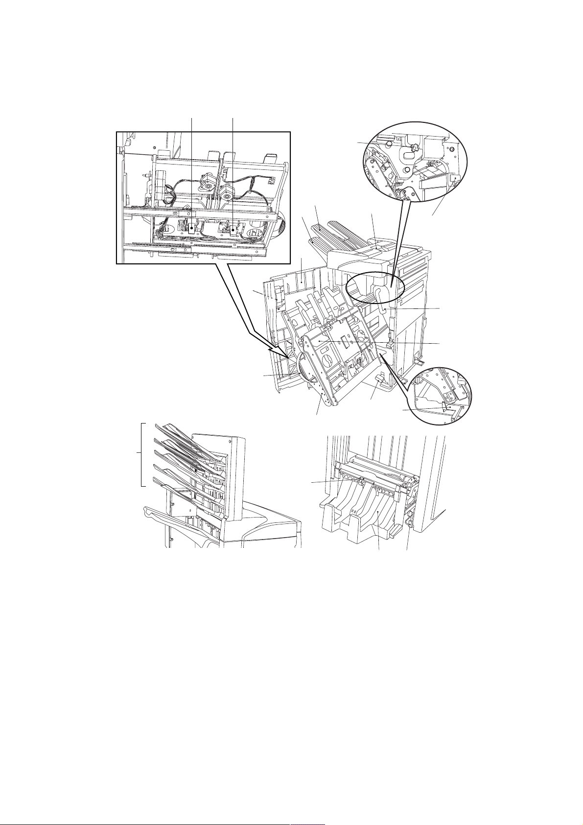
1-1-2 Part names and functions
3B8/9
!
0
4
7
1
3
8
2
5
@
#
9
$
Finisher
1 Main tray
2 Sub tray*
3 Front cover
4 Front cover handle
5 Upper cover
6 Intermediate tray
7 Intermediate tray handle
8 Conveyor knob
9 Intermediate tray release lever
0 Staple holder B*
! Staple holder A
@ Coupling section guide lever
%
^
6
&
*
(
Figure 1-1-1
Punch unit (option for multi finisher)
# Punch waste box
Multi job tray (option)
$ Job trays Nos.1 – 5
Centerfold unit (option for multi finisher)
% Unit release lever
^ Unit release handle
& Conveyor guide lever
* Storage cover
( Centerfold unit installation buttons
* For multi finisher only.
1-1-3
Page 13
3B8/9
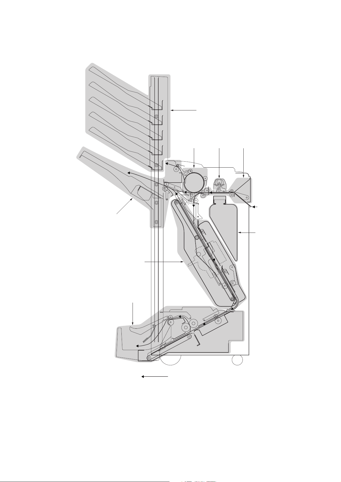
1-1-3 Machine cross sectional view
5
217
4
7
3
6
Paper path
1-1-4
1 Paper insertion section
2 Feedshift section
3 Intermediate tray section
4 Paper ejection section
Figure 1-1-2
5 Multi job tray (option)
6 Centerfold unit (option for multi finisher)
7 Punch unit (option for multi finisher)
Page 14
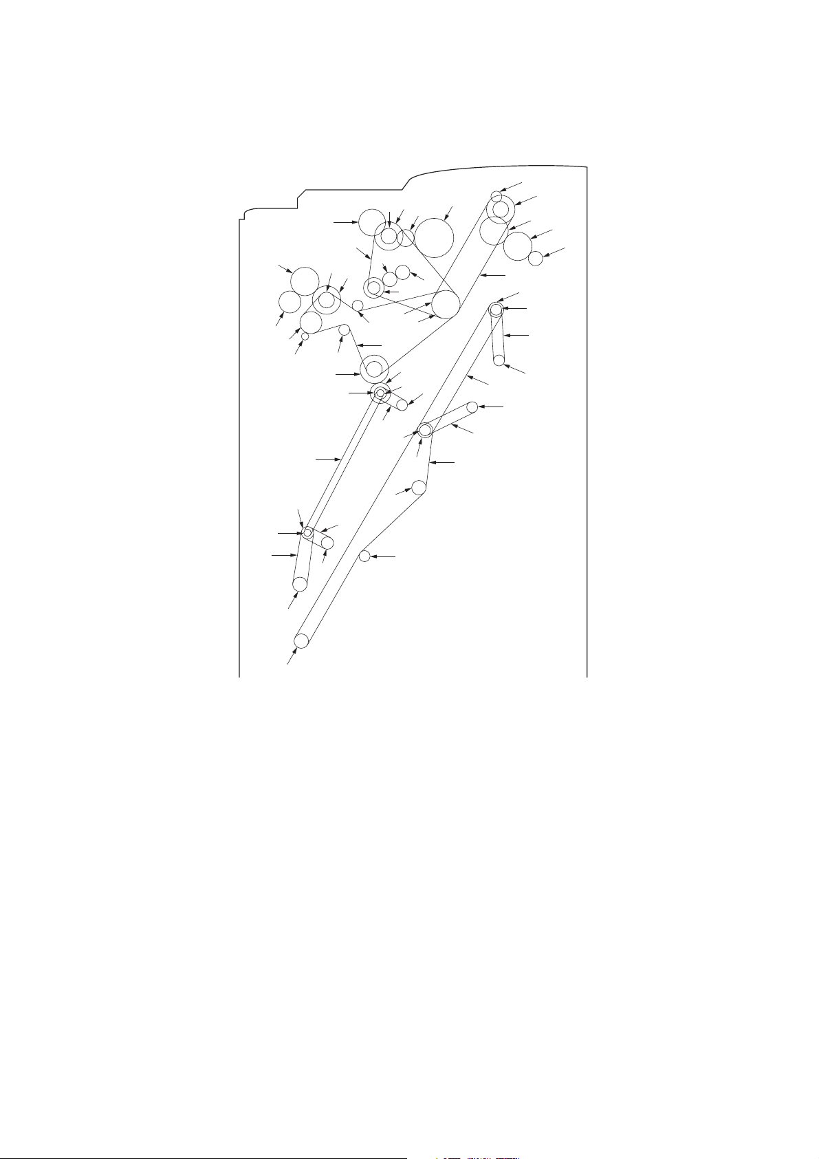
1-1-4 Machine drive system
˛
(1) Finisher (paper feed and conveying section)
fi
(
9
6
2
1
´
0
4
7
3
‚
5
⁄
Œ
›
8
*
Ó
‹
)
°
·
!
˝
fl
¤
„
‡
Ò
Ô
Ï
@
&
Î
Í
Å
”
$
3B8/9
#
%
^
1 Paper conveying motor gear
2 Pulley 37/48
3 Gear 40
4 Pulley 30
5 Tension pulley
6 Paper conveying clutch gear*
7 Tension pulley
8 Timing belt C
9 Paper entry roller gear
0 Gear Z40/P30
! Pulley 31 (machine rear)
@ Eject drive belt
# Gear Z21/38
$ Gear 40
% Gear 40
^ Eject roller gear
& Sub eject roller gear*
* Pulley 25 (machine front)
ˇ
‰
Á
ˆ
¨
Ø
( Siding drum drive belt
) Gear Z31/P18
⁄ Torque limiter gear 20
¤ Torque limiter gear 20
‹ Pulley 36
› Gear 20
fi Siding drum clutch gear*
fl Gear 26
‡ Gear 53
° Intermediate tray joint gear
· Pulley 16
‚ Pulley 20
ΠFeed belt
„ Upper forwarding roller
´ Pulley drive belt
‰ Pulley 16
ˇ Pulley 20
Á Feed belt
Ú
¸
Figure 1-1-3
¨ Lower forwarding roller
ˆ Paper forwarding pulley belt
Ø Pulley 27
∏ Upper paper conveying belt motor pulley
Å Intermediate tray drive belt
Í Pulley 20
Î Pulley 20
Ï Upper paper conveying belt
˝ Pulley 20
Ó Pulley 20
Ô Intermediate tray drive belt
Lower paper conveying belt motor pulley
Ò Lower paper conveying belt
Ú Pulley 20
¸ Tension pulley
˛ Pulley 20
* For multi finisher only.
1-1-5
Page 15
3B8/9
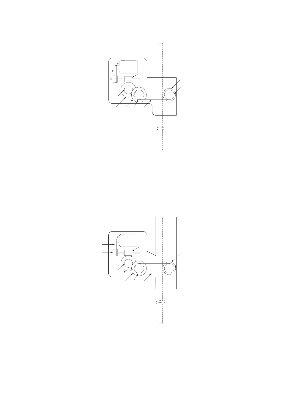
(2) Finisher (main tray driving section)
1
2
4
3
6
7
5
1 Main tray elevation motor pulley
2 Feed belt
3 Pulley 27
4 Worm gear
5 Gear 50
6 Gear 18
9
8
Figure 1-1-4
!
0
7 Gear 51
8 Pulley 20S
9 Tray drive belt
0 Pulley 20S
! Gear 26
(3) Multi job tray
1
2
4
3
6
7
5
1 Multi job tray elevation motor pulley
2 Feed belt
3 Pulley 27
4 Worm gear
5 Gear 50
6 Gear 18
9
8
Figure 1-1-5
!
0
7 Gear 51
8 Pulley 20S
9 Tray drive belt
0 Pulley 20S
! Gear 26
1-1-6
Page 16
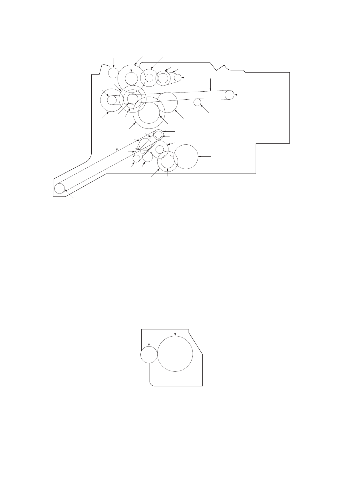
(4) Centerfold unit
3B8/9
›
%
$
6
8
9
‹
#
fl
0
7
fi
‡
(
„
)
·
45
3
2
!
¤
⁄
°
‚
Figure 1-1-6
@
1
^
&
*
Œ
1 Main motor pulley
2 Belt 118P2M6
3 Gear 22/40
4 Gear 33/15
5 Gear 51
6 Manual roller gear
(conveyor guide knob)
7 Gear 22
8 Gear 51
9 Gear 19
0 Gear 50/15
(5) Punch unit
! Gear 16/25
@ Gear 16/25
# Bypass pulley gear
$ Gear 58
% Pulley 28
^ Paper drive belt
& Pulley 28
* Idle pulley 15
( Centering plate motor pulley
) Belt 124
⁄ Pulley 22
12
¤ Pulley 20
‹ Paper conveying belt
› Pulley 20
fi Blade motor pulley
fl Belt 126P2M6
‡ Gear 22/40
° Gear 33/15
· Gear 40
‚ Gear 22
ΠGear 50
„ Manual roller gear
Figure 1-1-7
1 Punch motor gear
2 Punch clutch gear
1-1-7
Page 17
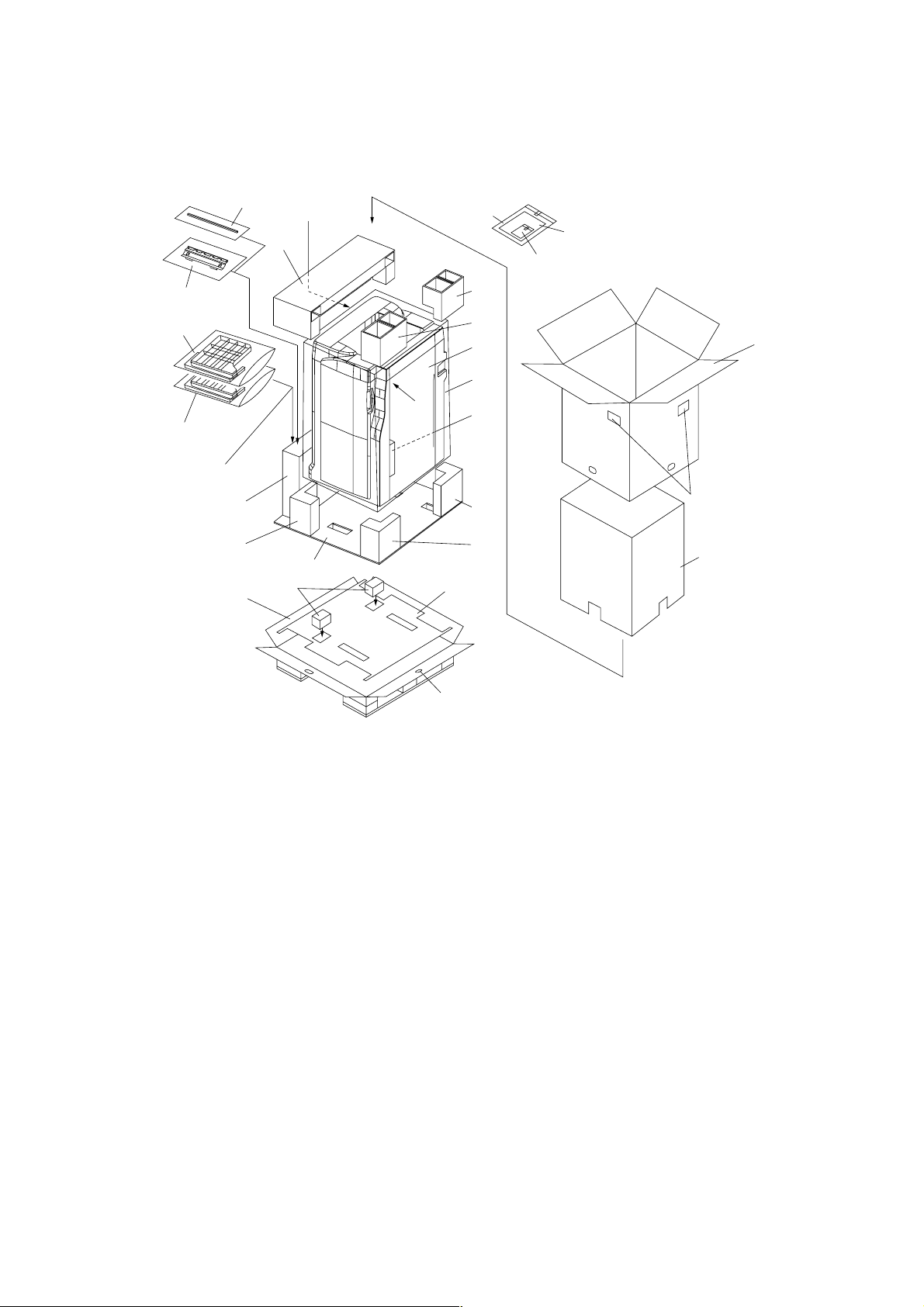
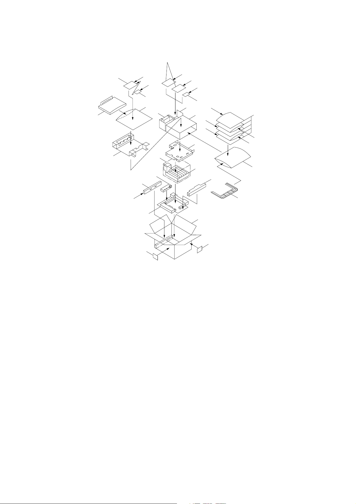
1-2-1 Unpacking and installing the machines
(1) Finisher
3B8/9
fl@
·2
·3
fl—4
5
ˇ#
›
&
%
⁄
Œ
Ø
^
∏
„
‹
¤
1
fi
*
)
(
Á
0!¨ˆ
´6789
$
‡
‚
1 Finisher
2 Main tray
3 Sub tray*
4 Finisher connecting plate
5 Stapler cartridge
6 Pins
7 Hexagonal nuts
8 M4 × 10 tap-tight binding screws
9 BVM4 × 12 binding screws
0 Label A
! Label B*
@ Paper insertion aid guide plate
# Connecting sponge
$ Outer case
‰
Figure 1-2-1 Finisher package
% Skid
^ Bottom cushion sheet
& Front lower left pad
* Rear lower left pad
( Front lower right pad
) Rear lower right pad
⁄ Upper left pad
¤ Front upper right pad
‹ Rear upper right pad
› Accessory case
fi Dust cover
fl Air cap bags
‡ Barcode labels
° Air cap bag
· Air cap bags
‚ Inner case
ΠBottom pads
„ Bottom board
´ Vinyl bag
‰ Hinge joint
ˇ Polyethylene bag
Á Polyethylene bag
¨ Instruction handbook
ˆ Installation guide
Ø Spacer
∏ Spacer
* For multi finisher only.
1-2-1
Page 18
3B8/9
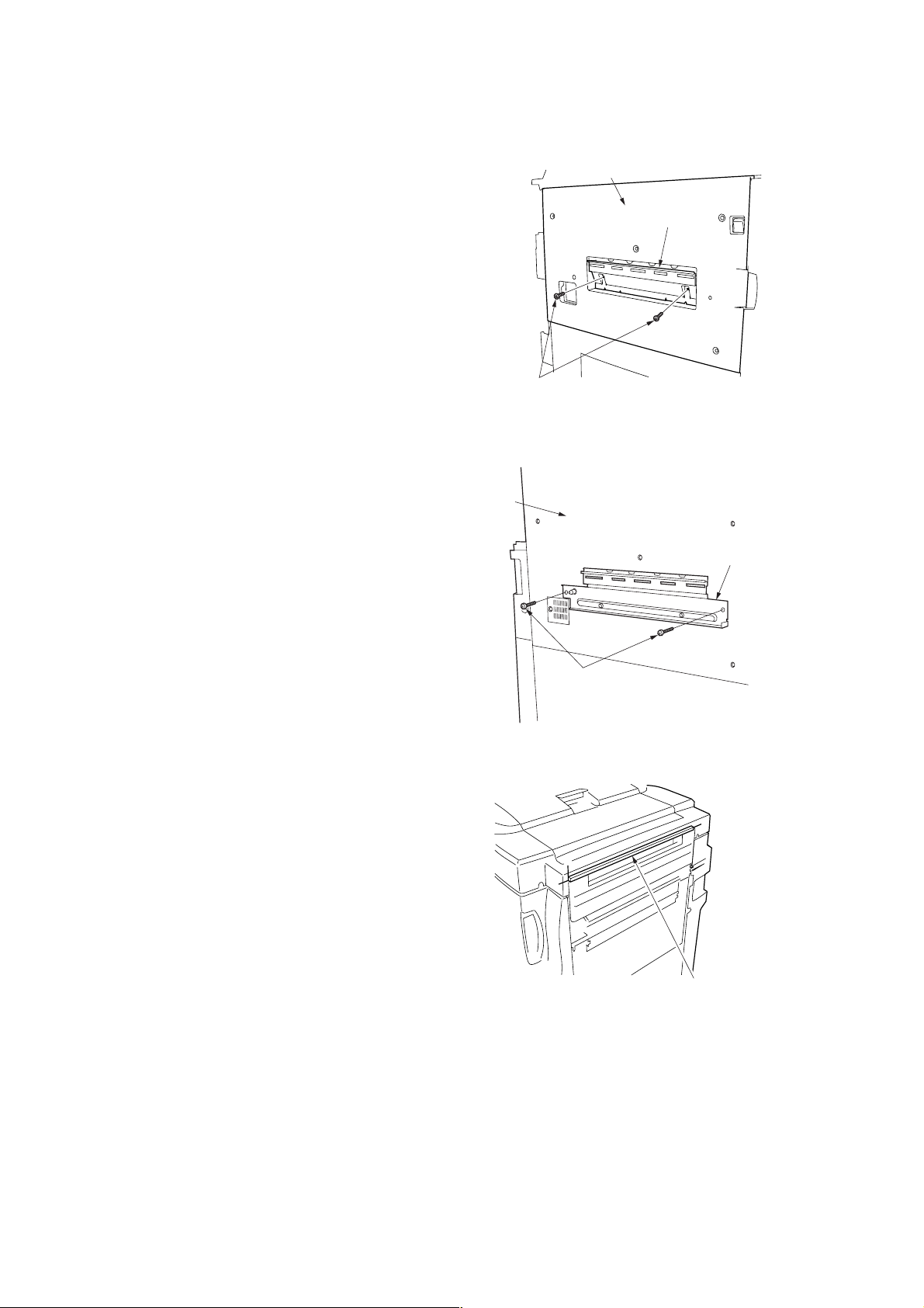
Installation procedure
Before installing the finisher, turn the copier off from the main switch and unplug the power cable from the wall outlet.
1. Attach the paper insertion aid guide plate to
the eject cover of the copier and lock down
with the two M4 × 10 tap-tight binding screws.
2. Attach the finisher connecting plate to the
copier eject cover and then hold them together
with the two BVM4 × 12 binding screws.
Eject cover
Paper insertion
aid guide plate
M4 × 10 tap-tight
binding screws
Figure 1-2-2
Eject cover
Finisher connecting plate
3. Attach the connecting sponge to the finisher by
aligning the sponge to the upper end “a” and
front end “b” of the paper port of the finisher.
BVM4 × 12 binding screws
Figure 1-2-3
a
b
a
Connecting sponge
Figure 1-2-4
1-2-2
Page 19
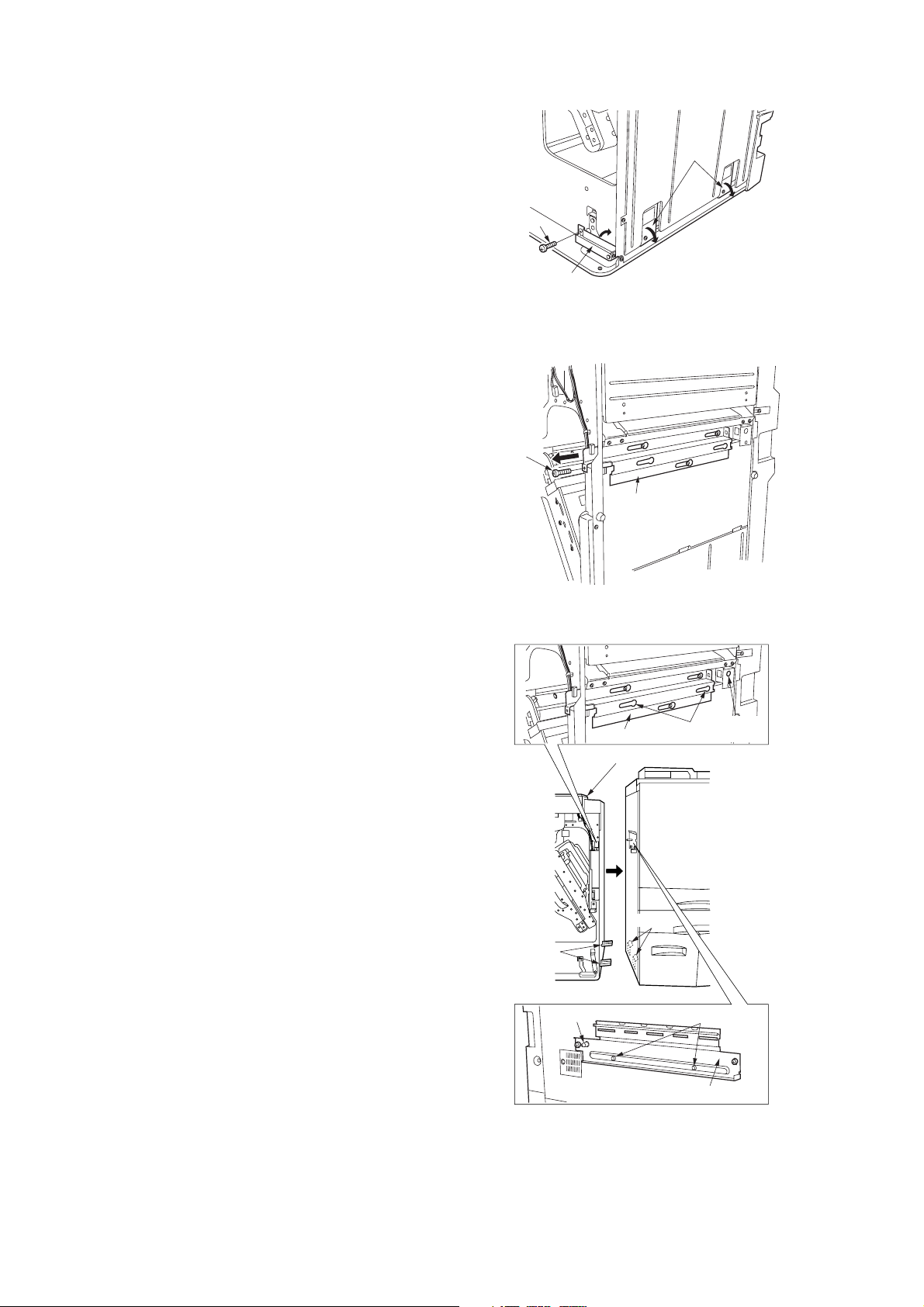
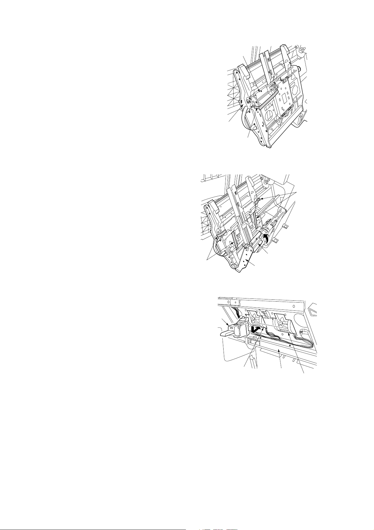
4. Open the front cover.
5. Remove the screw and raise the connecting
lever at the bottom of the finisher. Raising the
lever lowers the hooks.
6. Remove the screw and pull out the connecting
rail at the upper part of the finisher.
3B8/9
Hooks
Screw
Connecting
lever
Figure 1-2-5
Screw
Connecting rail
7. Join the finisher and the copier by hanging the
hooks onto the fittings inside the copier.
8. Join the finisher and the copier so that the long
pin of the finisher connecting plate is inserted
into the hole at the rear of the finisher and the
two short pins into the holes on the connecting
rail.
Hooks
Long pin
Figure 1-2-6
Connecting rail
Finisher
Fittings
Holes
Short pins
Hole at
the rear
Finisher connecting plate
Figure 1-2-7
1-2-3
Page 20
3B8/9
9. Make sure that the finisher is securely joined
with the copier. Then, push the connecting rail
in and lock back down with the screw.
10. Slide the connecting lever rightward and lock
down with the screw removed in step 5.
Connecting rail
Screw
Figure 1-2-8
11. Remove the four blue screws locking each of
the two separate retainers to the intermediate
tray and detach both retainers.
Retainers
Connecting lever
Figure 1-2-9
Blue screws
Screw
Intermediate
tray
1-2-4
Blue
screws
Figure 1-2-10
Page 21
3B8/9
p
12. Pull out the intermediate tray.
13. Remove the strip of fixing tape from the
release lever.
14. Raise the release lever to open the intermediate tray, and then remove the four strips
of fixing tape.
Release lever
Intermediate
tray
Fixing tape
stri
Figure 1-2-11
Fixing tape
strips
15. Insert a stapler cartridge into each of the
staplers of the intermediate tray. Press on the
cartridges until they are securely locked.
Note: With the simple finisher, attach just one
stapler cartridge to the stapler at the rear side.
Fixing tape
strips
Stapler
cartridge
Intermediate tray
Figure 1-2-12
Stapler
Figure 1-2-13
Release lever
Intermediate
tray
Stapler
1-2-5
Page 22
3B8/9
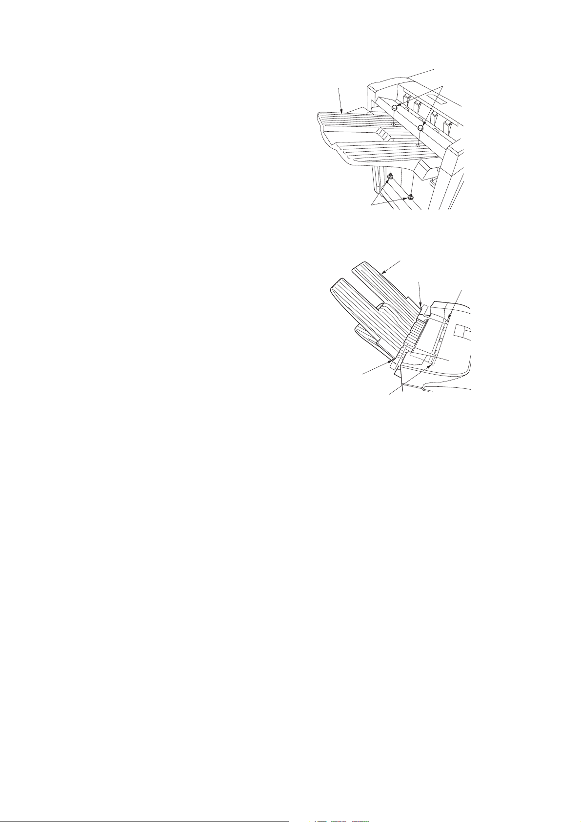
16. Fit the main tray with two hexagonal nuts.
17. Secure the main tray with two pins.
For the multi finisher only
18. Attach the sub tray to the finisher by inserting
the projections at the front and back of the sub
tray into the holes of the finisher.
Main tray
Hexagonal nuts
Pins
Figure 1-2-14
Sub tray
Projection
Hole
Projection
Hole
Figure 1-2-15
1-2-6
Page 23
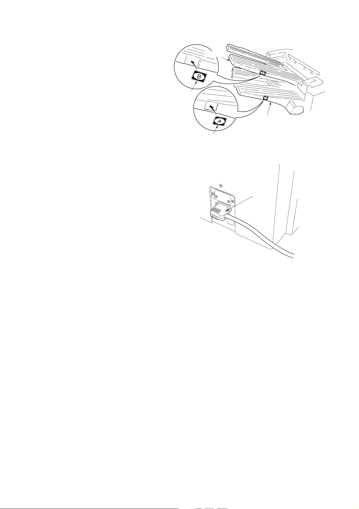
19. Affix label A to the recessed portion on the side
of the main tray.
For multi finisher only
20. Affix label B to the recessed portion on the side
of the sub tray.
21. Connect the signal cable of the finisher to the
connector of the copier.
22. Plug the copier’s power cable into a wall outlet
and turn the copier on from the main switch.
3B8/9
Sub tray
Label B
Main tray
Label A
Figure 1-2-16
Signal cable
Adjustment
After installing the multi/simple finisher, perform the following adjustment.
• Correcting paper curling
See page 1-5-1.
• Correcting centerfold-stapling (for multi finisher only)
See page 1-5-2.
Figure 1-2-17
1-2-7
Page 24
3B8/9
(2) Multi job tray
‰
6
´
‡
———
234
$%Œ
*
^
‚
00
„„
‹
)
fi
·
8
fl
9
!@#
„
(
5
&
1
⁄
5
¤
5
5
5
‹
›
7
‚
Figure 1-2-18 Multi job tray package
1 Multi job tray
2 Bin front guide plate
3 Bin rear guide plate
4 Bin guide plate retainer
5 Job trays
6 Right cover
7 Left cover
8 Tray detection plate A
9 Motor front cover
0 Job tray switches
! BVM3 × 5 binding screws
@ BVM4 × 6 binding screws
# M4 × 8 TP screws
$ Sheet of tray No. labels
% Sheet of name labels
^ Bottom pad
& Top pad
* Rail case
( Tray spacer
) Spacer
⁄ Outer case
¤ Air cap bags
‹ Air cap bags
› Front bottom spacer
fi Rear bottom spacer
fl Retaining spacer
‡ Top spacer
° Polyethylene bags
· Dust cover
‚ Barcode labels
ΠInstallation guide
„ Vinyl bags
´ Polyethylene bag
‰ Vinyl bags
1-2-8
Page 25
3B8/9
Installation procedure
Before installing the multi job tray, turn the copier off from the main switch and unplug the power cable from the wall outlet.
Install the multi job tray after attaching the finisher main tray.
When installing the multi job tray and centerfold unit as a set, first install the centerfold unit and then the multi job tray.
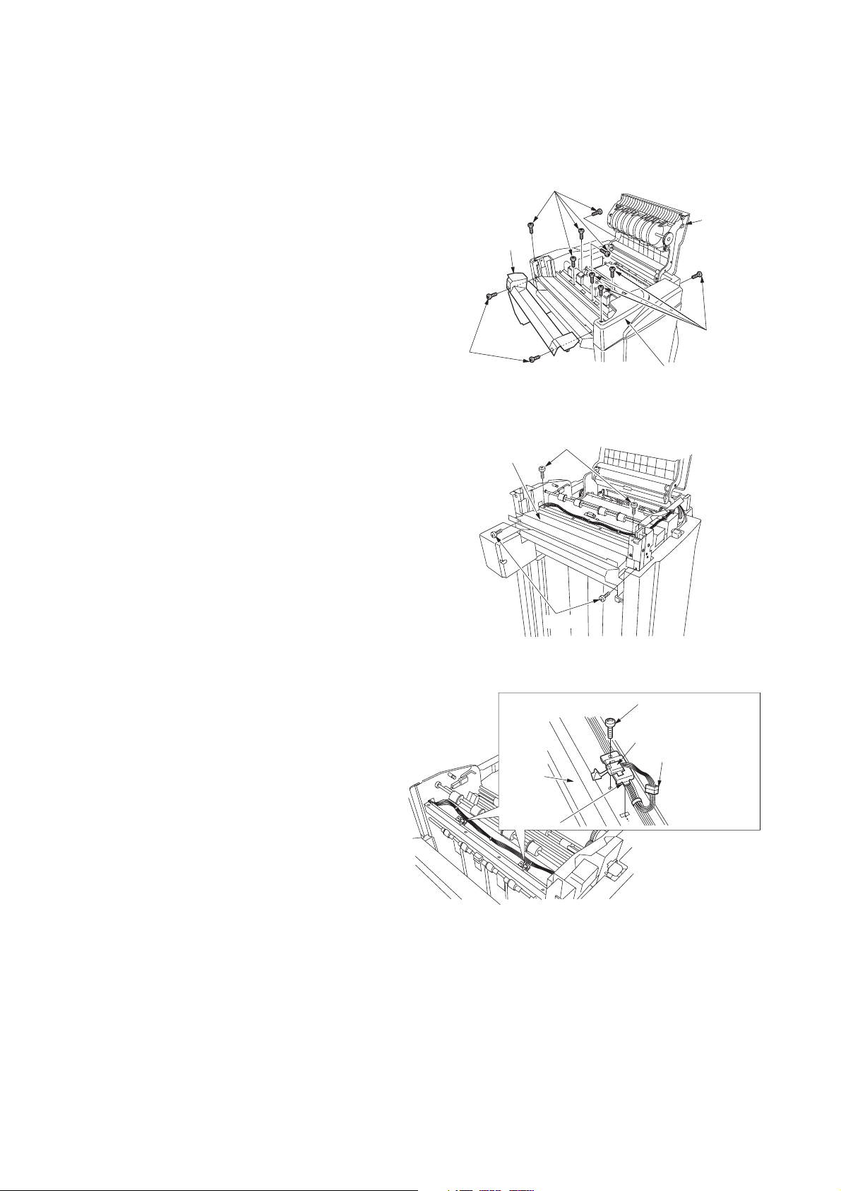
1. Remove the two screws locking down the top
cover lid followed by the lid.
2. Open the upper cover and remove the nine
screws locking down the top cover followed by
the top cover.
3. Remove the four screws locking down the top
cover lid guide followed by the guide.
Screws
Top cover lid
Top cover
lid guide
Screws
Upper
cover
Screws
Top cover
Figure 1-2-19
Screws
4. Attach the two multi job tray switches to the
eject stay by inserting the tabs, and lock in
place with one BVM3 × 5 binding screw each.
5. Connect the 3-pin connector of the size
detection switch to the connector of the
finisher.
Screws
Figure 1-2-20
BVM3 × 5
binding screw
Multi job tray switch
3-pin connector
Eject
stay
Ta b
Figure 1-2-21
1-2-9
Page 26
3B8/9
When installing the multi job tray and centerfold unit as a set, follow steps 6 to 18. When installing the multi job tray only, skip
to step 19.
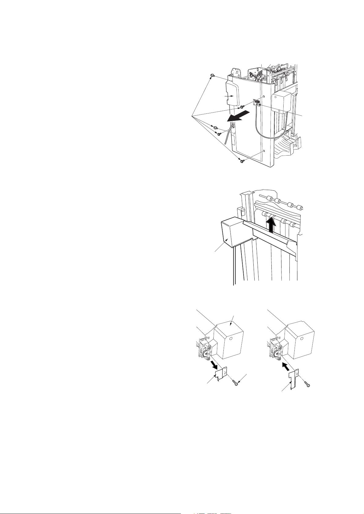
6. Disconnect the 2-pin connector of the main
tray unit.
7. Remove the five screws locking down the
finisher rear cover followed by the cover.
Rear
cover
8. Raise the main tray unit by hand and detach
from the finisher.
Screws
2-pin
connector
Figure 1-2-22
Main tray unit
9. Remove the screw locking the tray detection
plate to the main tray unit. Replace the tray
detection plate with tray detection plate A
included in the package.
Figure 1-2-23
Main tray unit
Screw
Tray detection plate
Tray detection plate A
Figure 1-2-24
1-2-10
Page 27
3B8/9
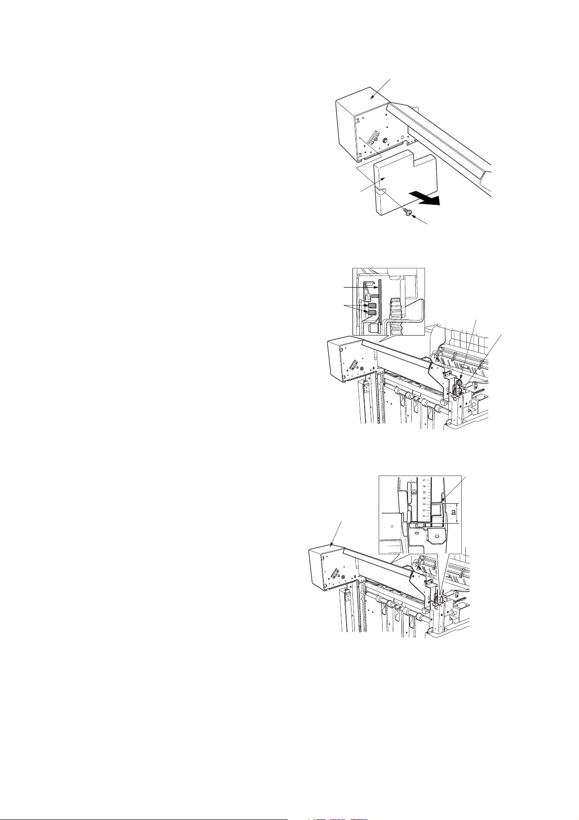
10. Remove the screw locking the motor front
cover to the main tray unit followed by the
cover.
11. Attach the main tray unit to the finisher by
inserting the main tray pulleys at the unit front
and rear into the rails on the finisher.
Note: Be sure that tray detection plate A does
not make contact with the sensors.
Main tray unit
Motor front cover
Screw
Figure 1-2-25
Tray detection
plate A
Sensors
Main tray pulley
Rail
12. Measure the gaps “a” between the main tray
unit and finisher rail ends against the scale to
make sure that “a” is same at the front and
rear.
Note: If gap “a” is not the same at the unit front
and rear, install the main tray unit again so that
it becomes the same.
Figure 1-2-26
Rail end
Main tray unit
Figure 1-2-27
1-2-11
Page 28
3B8/9
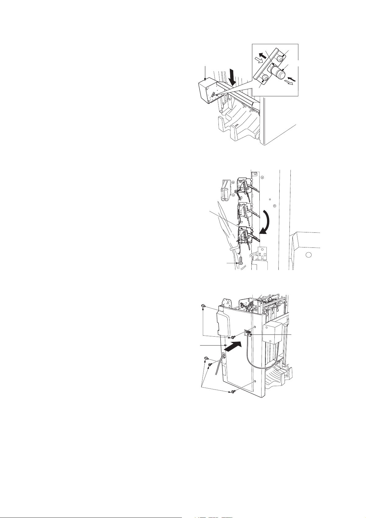
13. Loosen the two screws locking down the
retainer. With the retainer slid upward, push in
the gear shaft while holding the bottom of the
main tray unit. Then, lower the main tray unit to
its lowest position.
14. Pull out the gear shaft, slide the retainer to its
original position and retighten the two screws.
Note: Make sure the gear shaft is positioned
so that the retainer will be engaged in groove
“b” on the shaft.
15. Insert the two pegs of the motor front cover of
the main tray unit into the square holes and
lock down with the screw.
16. Remove the screw locking the mid-point
detection sensor to the finisher rear panel.
Lower the sensor and lock it down again.
Main tray unit
Mid-point
detection sensor
Screw
Figure 1-2-28
b
Screw
Gear shaft
17. Reattach the finisher rear cover with the five
screws.
18. Connect the 2-pin connector of the main tray
unit.
Screws
Rear cover
Screws
Screw
Figure 1-2-29
2-pin connector
Figure 1-2-30
1-2-12
Page 29
3B8/9
19. Remove the three blue screws locking the
base retainer to the multi job tray followed by
the retainer.
20. Attach the bin front guide plate and bin rear
guide plate to the finisher by inserting the
claws on plates into the finisher frame and lock
in place with three BVM4 × 6 binding screws
each.
Base retainer
Bin rear
guide plate
BVM4 × 6
binding screws
Multi job tray
Blue screws
Figure 1-2-31
Bin front guide plate
21. Attach the multi job tray to the bin front guide
plate and bin rear guide plate by inserting the
six pulleys at the tray front and rear into the
plates.
Note: Make sure that the shading plate at the
rear of the multi job tray does not make contact
with the sensor.
BVM4 × 6
binding screws
Multi job tray
BVM4 × 6
binding screws
Figure 1-2-32
Shading
plate
Sensor
Bin front guide plate
Pulleys
Bin rear
guide plate
Pulleys
Figure 1-2-33
1-2-13
Page 30
3B8/9
22. Measure the height “a” against the scale to
make sure that the multi job tray is positioned
properly to stay level from front to rear.
If the height “a” is not the same at the front and
rear, the multi job tray may not be positioned
on a level plane. Install the tray again.
23. Loosen the two screws.
24. With the retainer slid upward, push in the gear
shaft while holding the bottom of the multi job
tray. Then, lower the multi job tray by about
30 mm.
Bin rear
guide plate
Multi job tray
Multi job tray
a
a
Figure 1-2-34
Screws
Retainer
Bin front
guide plate
Gear shaft
25. Pull out the gear shaft, slide the retainer to its
original position and retighten the two screws.
Note: Make sure the gear shaft is positioned
so that the retainer will be engaged in groove
“b” on the shaft.
Figure 1-2-35
Screws
b
Retainer
Gear shaft
Figure 1-2-36
1-2-14
Page 31

3B8/9
26. Attach the bin guide plate retainer with two
BVM4 × 6 binding screws.
27. Reattach the top cover with the nine screws
removed in step 2, keeping the upper cover
open halfway to enable proper attaching.
28. Attach the right cover with four M4 × 8 TP
screws.
BVM4 × 6 binding screws
Bin guide
plate retainer
Figure 1-2-37
Right cover
M4 × 8 TP
screws
M4 × 8
TP screws
29. Attach the left cover by inserting the two pegs
into the square holes, and lock in place with
two M4 × 8 TP screws.
Figure 1-2-38
M4 × 8 TP screws
Left cover
Peg
Peg
Figure 1-2-39
1-2-15
Page 32

3B8/9
30. Affix a tray No. label to each of the five job
trays.
31. Attach the job tray with the label No.1 affixed at
the uppermost shelf of the multi job tray by
inserting the three claws into the square holes.
Job tray
Tray No. label
Figure 1-2-40
Claws
Job tray
Figure 1-2-41
32. Connect the 3-pin connector at the back side
of the job tray.
33. Fit the cable of the 3-pin connector to the
inside of the job tray and lock down with the
cable retainer.
34. Slide the job tray lid into position and lock in
place by inserting the two pegs into the square
holes.
Note: Make sure that the cable is tidily fitted
and not caught in the job tray lid.
35. Repeat steps 31 to 34 to attach the other four
job trays.
Note: Attach the job trays in the order of the
tray No. labels so that the tray with the label
No.1 is at the uppermost shelf, No.2 at the
second and so forth.
Peg
3-pin connector
Job tray
Job tray lid
Peg
Cable
Cable retainer
1-2-16
Figure 1-2-42
Page 33

36. Attach the motor front cover by inserting the
two pegs into the square holes, and lock in
place by the M4 × 8 TP screw.
3B8/9
Pegs
37. Connect the signal cable of the multi job tray to
the finisher connector.
38. Plug the copier’s power cable into a wall outlet
and turn the copier on from the main switch.
39. Make a test print and check the multi job tray
performs properly.
Motor front cover
M4 × 8 TP screw
Figure 1-2-43
Signal cable
Figure 1-2-44
1-2-17
Page 34

3B8/9
(3) Centerfold unit
Á
ˇ
Ç
&
^
%
#
ı
‰
´
„
8
@
0
9
Œ
‚
·
°
‡
fl
Ø
*
◊
ˆ
ı
6
5
$
4
7
Â
!
˝
Ô
ı
˜
Ú
Ò
Ï
˝
¸
Í
Ó
˜
(
‹
˛
)
›
1
∏
⁄
fi
¤
Î
Å
1 Centerfold unit
2 Release pole assembly
3 Release stopper pole assembly
4 Storage cover
5 Right cover
6 Left cover
7 Release handle
8 Sliders
9 Release lever
0 Release pole retainer
! Release lever actuating plate
@ Backstop
# Detection PI douser
$ Unit transport handle
% Unit lock hook
^ Unit lock rod
& Tray stopper
* Eject guide upper spacer
( Unit insertion label
¸
2
3
Figure 1-2-45 Centerfold unit package
) Jam correction label
⁄ Jam correction label (Japan)
¤ Jam correction label (export)
‹ Operation label 1
› Operation label 2
fi Operation label 3
fl Large stop rings
‡ Medium stop ring
° Small stop ring
· Pins
‚ Small springs
ΠLarge spring
„ BVM4 × 6 bronze binding screws
´ M4 × 6 TP-A bronze screws
‰ M4 × 10 TP-A bronze screw
ˇ BVM3 × 5 bronze binding screw
Á M3 × 10 tapping screws
¨ Outer case
ˆ Accessory case
¨
Ø Air cap bags
∏ Unit bottom pad
Å Unit left spacer
Í Unit rear spacer
Î Unit front spacer
Ï Unit case
˝ Top and bottom pads
Ó Left spacer
Ô Right spacer
Arm spacer
Ò Centerfold blade spacers
Ú Installation guide
¸ Barcode labels
˛ Dust cover
Ç Vinyl bag
◊ Polyethylene bag
ı Vinyl bags
˜ Polyethylene bags
 Air cap bag
1-2-18
Page 35

3B8/9
Installation procedure
Before installing the centerfold unit, turn the copier
off from the main switch and unplug the power
cable from the wall outlet.
When unpacking or installing, hold the centerfold
unit by “a” indicated in the illustration. Do not hold it
by “b” at the center of the unit.
When installing the multi job tray and centerfold
unit as a set, first install the centerfold unit and
then the multi job tray.
1. Disconnect the 2-pin connector of the main
tray unit.
2. Remove the five screws locking down the
finisher rear cover followed by the cover.
Screws
b
a
a
Figure 1-2-46
Rear
cover
2-pin
connector
3. Disconnect the 3-pin connector of the sensor.
Figure 1-2-47
3-pin connector
Figure 1-2-48
1-2-19
Page 36

3B8/9
4. Remove the screw from the rear of the
reinforcing plate.
5. Insert the tray stopper and lock it down with the
screw removed in step 4 and the BVM4 × 6
bronze binding screw.
Note: When inserting the tray stopper, take
care not to damage the sensors.
6. Reconnect the 3-pin connector that was
disconnected in step 3.
7. Reattach the finisher rear cover with five
screws.
8. Connect the 2-pin connector of the main tray
unit.
Tray stopper
BVM4 × 6
bronze binding
screw
Screw
Figure 1-2-49
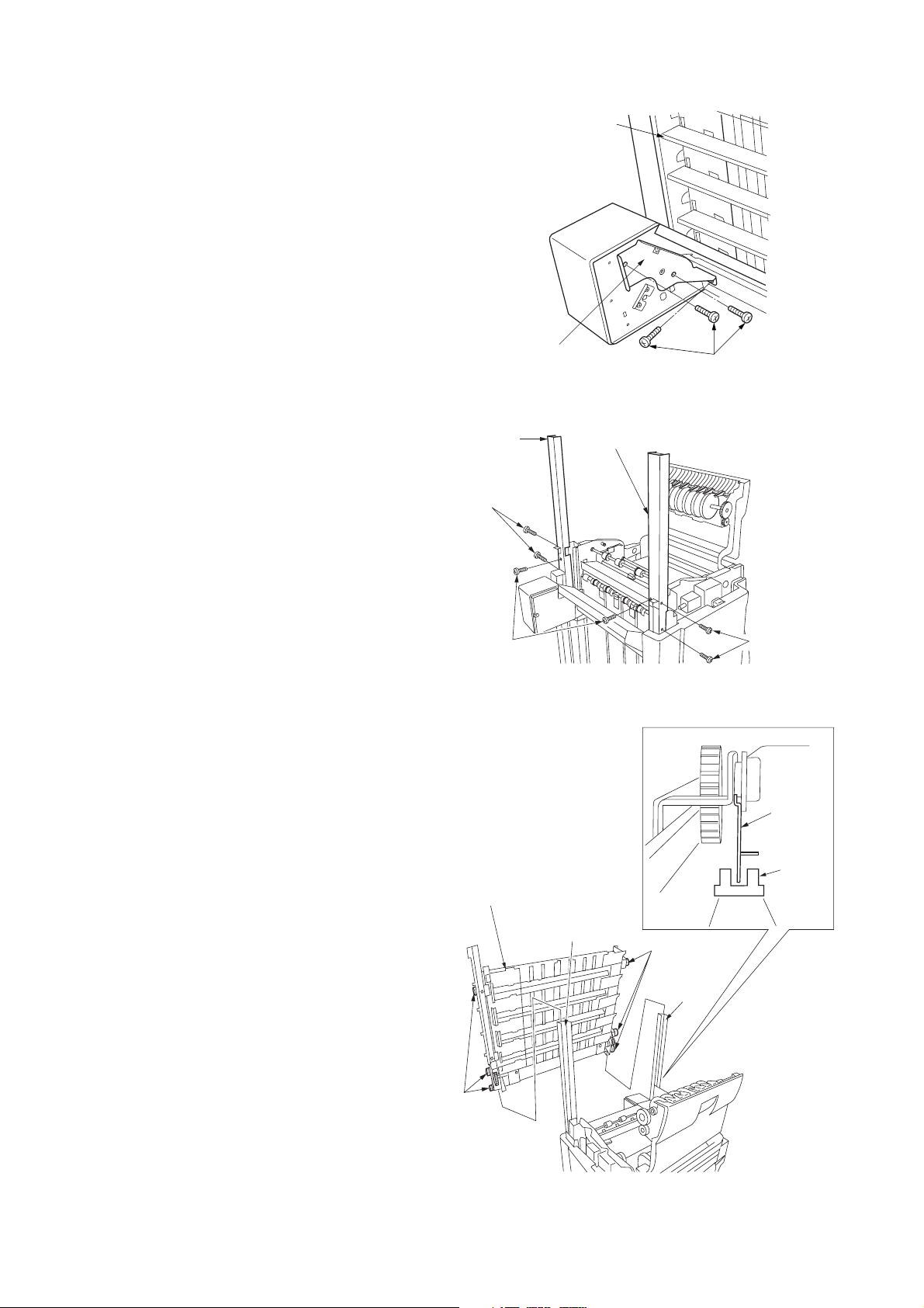
9. Remove the four screws locking down the
guide plate followed by the plate.
10. Remove the left lower shaft from the finisher
side plate.
Screws
Rear cover
Screws
2-pin connector
Figure 1-2-50
Guide plate
Screws
Left lower shaft
Figure 1-2-51
1-2-20
Page 37

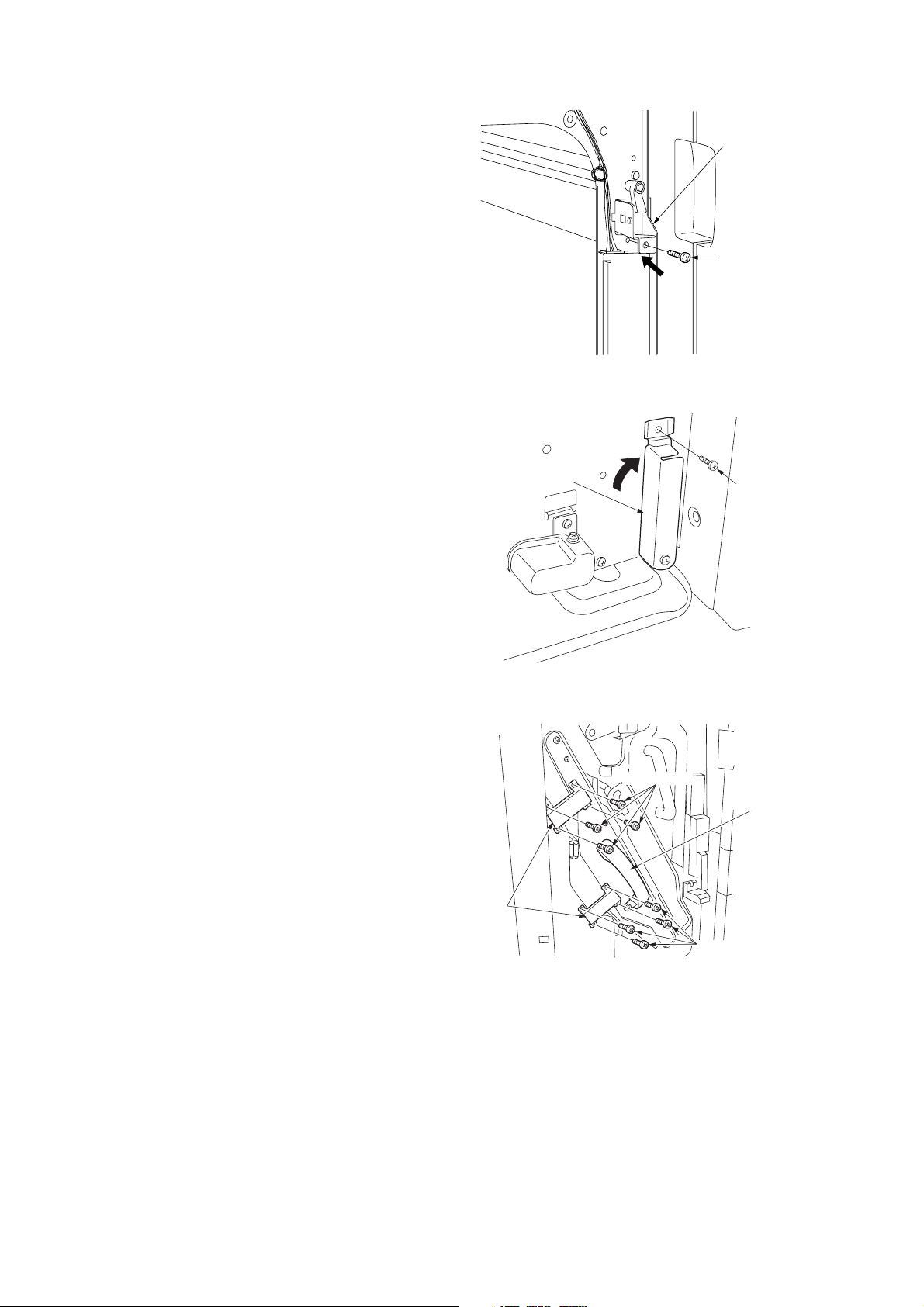
3B8/9
11. Open the front cover. Remove the screw
locking down the retainer followed by the
retainer.
12. While keeping the front cover perpendicular to
the copier, detach the cover by raising it
vertically in the direction of the arrow.
13. Hang the backstop over the claw on the side
plate and fit with two pins.
14. Attach one end of the small spring to the
backstop and hang the other end over the
hook inside the machine.
Front cover
Figure 1-2-52
Backstop
Screw
Retainer
Hook
Claw
Pins
15. Insert the rear end of the release stopper pole
assembly into the bypass hole and the front
end into the mounting hole.
Note: When attaching the assembly, make
sure the release stopper is orientated
correctly.
16. Insert the rear end of the release stopper pole
assembly already inserted through the bypass
hole into the mounting hole on the opposite
side.
Hook
Backstop
Small
spring
Figure 1-2-53
Mounting hole
Front end
Bypass hole
Release
stopper
Mounting hole
Figure 1-2-54
Release stopper
pole assembly
Front end
1-2-21
Page 38

3B8/9
p
y
17. Fit the small stop ring into the groove on the
left side of the release stopper pole assembly.
Push the release stopper pole assembly in the
direction of the arrow.
18. Attach the release lever to the release stopper
pole assembly with the BVM3 × 5 bronze
binding screw.
Small stop ring
Groove
Release stopper
ole assembl
Figure 1-2-55
BVM3 × 5 bronze
binding screw
Release lever
Release stopper
pole assembly
19. Loosely attach the release pole retainer with
an BVM4 × 6 bronze binding screw.
Figure 1-2-56
Release pole
retainer
BVM4 × 6 bronze binding screw
Figure 1-2-57
1-2-22
Page 39

20. Insert the release lever actuating plate through
the hole to the inside of the machine and fit
with two pins. Then, make sure that the
release lever actuating plate slides leftward
and rightward.
3B8/9
Release
lever
actuating
plate
21. Attach one end of the small spring to the
release lever actuating plate and hang the
other end over the hook on the side plate.
22. Coat the release lever actuating plate with
TEMP1 or the similar grease in the indicated
area “a”.
Pin
Release lever
actuating plate
Hole
Release lever
actuating plate
Pin
Figure 1-2-58
Release lever
actuating plate
Hook
Small spring
Figure 1-2-59
a
1-2-23
Page 40

3B8/9
23. Insert one end of the release pole assembly
into the square bypass hole and the other end
into the hole with the projection, with the D-cut
of the release pole assembly aligned with the
projection.
24. Insert the end of the release pole assembly
already inserted through the square bypass
hole into the mounting hole.
Mounting hole
Bypass
hole
Release pole
assembly
Bypass hole
Mounting hole
Hole
D-cut
25. Fit the medium stop ring onto the release pole
assembly. Then, make sure the release pole
assembly can rotate slightly.
26. Attach the release handle to the release pole
assembly at the machine front side with an
M4 × 10 TP-A bronze screw.
Release pole assembly
Figure 1-2-60
Medium stop ring
Release pole
assembly
Figure 1-2-61
Front end
Release
handle
1-2-24
M4 × 10 TP-A
bronze screw
Figure 1-2-62
Page 41

3B8/9
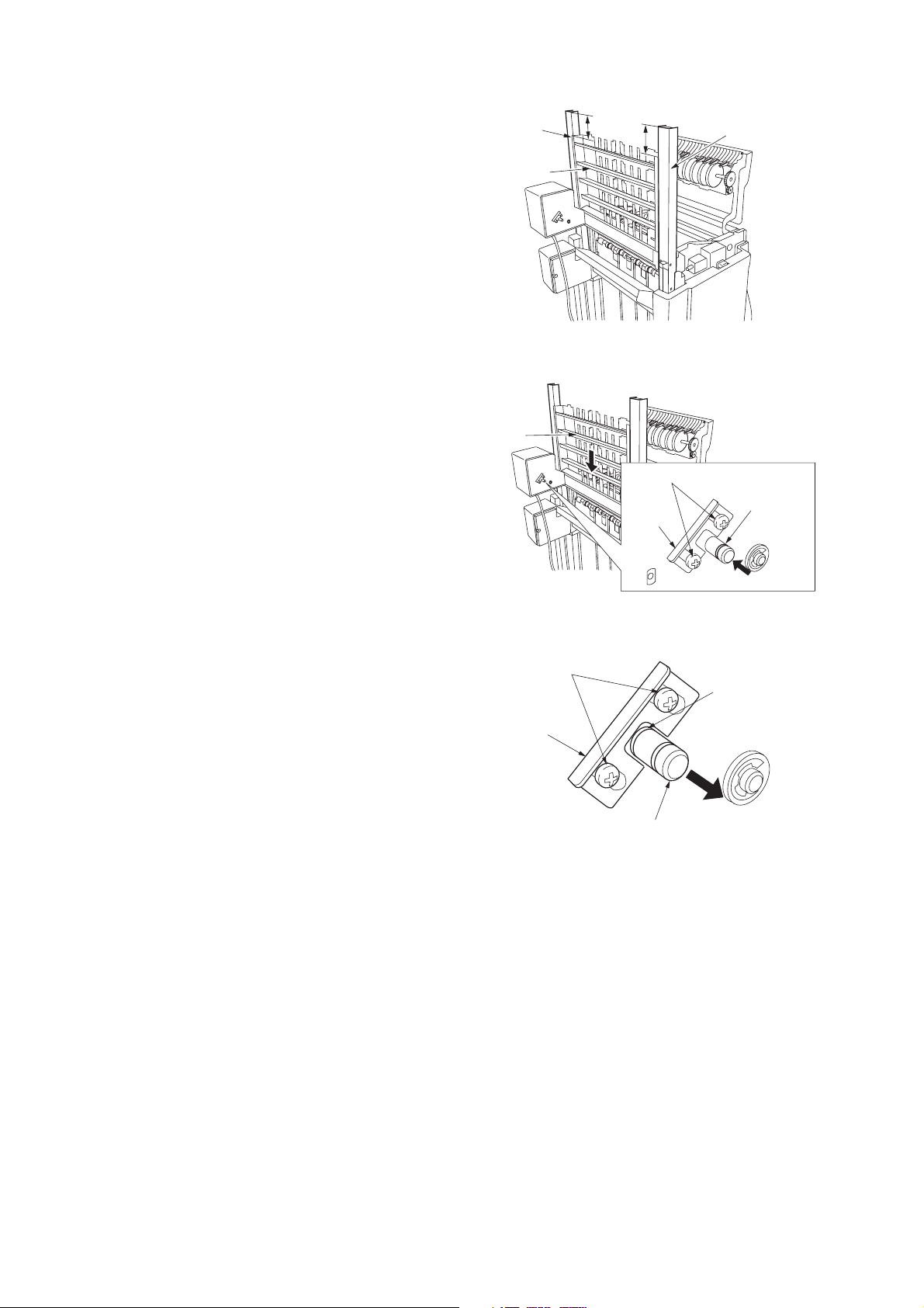
27. Place the slider on the projections on the
finisher rear side-plate and lock down with
three BVM4 × 6 bronze binding screws.
Note: Insert the screws from the round holes
on the eject side of the finisher.
28. Place the slider on the projections on the
finisher front side-plate and lock down with
three BVM4 × 6 bronze binding screws.
Note: Insert the screws from the round holes
on the eject side of the finisher.
29. Pull out the intermediate tray.
30. Fit the large stop ring onto the unit lock rod.
31. Attach the unit lock hook to the guide stay with
the unit lock rod.
Projections
BVM4 × 6 bronze
binding screws
Unit
lock rod
Slider
Large stop
ring
BVM4 × 6 bronze
binding screws
Projections
Sliders
Figure 1-2-63
Guide stay
Guide stay
Unit lock hook
Unit lock hook
Intermediate tray
Figure 1-2-64
1-2-25
Page 42

3B8/9
32. Fit the large stop ring onto the lower part of the
unit lock rod.
33. Hang one end of the large spring over the hook
on the unit lock hook and the other end over
the hook on the guide stay.
34. Remove the eight strips of fixing tape and the
cushioning material from the centerfold unit.
Hook
Large spring
Fixing tape strip
Guide stay
Unit lock rod
Large stop ring
Unit lock hook
Hook
Figure 1-2-65
Fixing tape strip
35. Pull the left and right sliders out until they stop.
Attach the centerfold unit on the pins of the
sliders.
Note: Hold the centerfold unit by “a” indicated
in the illustration. Do not hold it by “b” at the
center of the unit.
Fixing tape strip
Cushioning material
Fixing tape strips
Fixing tape
strips
Sliders
Figure 1-2-66
b
a
Fixing tape strip
Centerfold
a
unit
Pins
Fixing tape strip
1-2-26
Figure 1-2-67
Page 43

36. Slide the centerfold unit in the direction of the
pp
arrow.
37. Loosen the two screws and push the retainer
in the direction of the arrow and retighten the
screws.
Screw
Retainer
3B8/9
Screw
Retainer
38. Attach the left and right covers by inserting the
catches of the left and right covers into the
square holes on the front and rear side-plates,
respectively, of the centerfold unit with one
M4 × 6 TP-A bronze screw each.
Screw
M4 × 6 TP-A
bronze screw
Left cover
Screw
Centerfold unit
Figure 1-2-68
M4 × 6 TP-A
bronze screw
Right cover
Centerfold unit
39. Attach the eject guide upper spacer with the
three M3 × 10 tapping screws.
Figure 1-2-69
M3 × 10 tapping screws
Eject guide
u
Figure 1-2-70
er spacer
1-2-27
Page 44

3B8/9
40. Attach the storage cover to the centerfold unit
by inserting the projection of the tray into the
hole inside the unit.
41. Engage the projection of the detection PI
douser with the cutout on the centerfold unit
rear panel and lock down the douser with the
BVM4 × 6 bronze binding screw.
Note: When inserting the centerfold unit, make
sure that the detection PI douser does not
make contact with the finisher’s centerfold unit
set switch. If it does, bend the douser with your
hand as much as needed so that the contact is
avoided.
Centerfold unit
Hole
Projection
Storage cover
Figure 1-2-71
42. Pull the release lever in the direction of the
arrow and push in the centerfold unit.
Detection PI douser
BVM4 × 6 bronze
binding screw
Figure 1-2-72
Release lever
Centerfold unit
Figure 1-2-73
1-2-28
Page 45

43. Push the release lever actuating plate.
44. Push in the centerfold unit until it stops.
3B8/9
Release lever actuating plate
Centerfold unit
Figure 1-2-74
45. Push the release stopper pole assembly in the
direction of the arrow and tighten the BVM4 × 6
bronze binding screw that loosely attached the
release pole retainer.
46. Attach the unit transport handle with an
BVM4 × 6 bronze binding screw.
Release pole retainer
Release stopper pole assembly
BVM4 × 6 bronze binding screw
Figure 1-2-75
Unit transport
handle
BVM4 × 6 bronze
binding screw
Figure 1-2-76
1-2-29
Page 46

3B8/9
47. Affix the jam correction label on the rating plate
of the finisher front side-plate, in a point 15 mm
from each “a” and “b”.
Jam correction label
Rating plate
Figure 1-2-77
b
15 mm
a
15 mm
48. Reattach the front cover.
49. Affix the unit insertion label to the right cover
aligning the label with the left end and bottom
of the cover.
50. Affix operation labels 1 and 2 to the finisher
front panel as shown in the illustration.
Unit insertion
label
Operation label 1
Right cover
Figure 1-2-78
15 mm
5 mm
Operation
label 2
1-2-30
Figure 1-2-79
Page 47

51. Affix operation label 3 to the finisher’s
intermediate tray handle as shown in the
illustration.
52. Affix the jam correction label (export) over the
existing label on the inside of the finisher front
cover, as shown in the illustration.
3B8/9
15 mm
Operation label 3
Figure 1-2-80
53. Plug the copier’s power cable into a wall outlet
and turn the copier on from the main switch.
54. Make a test copy to check that the centerfold
unit operates correctly.
Adjustment
After installing the centerfold unit, perform the following adjustment.
• Adjusting the paper folding position
See page 1-5-5.
Jam correction
label (export)
Figure 1-2-81
1-2-31
Page 48

3B8/9
(4) Punch Unit
2
#
(
$
0
!
&
3
5
%
@
#
1
9
6
Figure 1-2-82 Punch unit package
1 Punch unit
2 Paper conveying unit
3 Punch waste box
4 Paper conveying unit upper guide
5 M4 × 6 TP screws
6 Outer case
7 Bottom pad A
8 Bottom pad B
9 Upper left pad
0 Upper right pad
*
#
8
7
4
^
! Right pad
@ Spacer
# Polyethylene bags
$ Installation guide
% Vinyl bag
^ Bar code labels
& Polyethylene bag
* Rust-proofing sheet
( Supply parts check list
1-2-32
Page 49

3B8/9
Procedure
Before installing the punch unit, turn the copier off from the main switch and unplug the power cable from the wall outlet.
1. Remove the two screws locking down the top
cover lid followed by the lid.
2. Open the upper cover and remove the nine
screws locking down the top cover followed by
the top cover.
3. Open the front cover.
4. Remove the three screws locking down the
right inner cover followed by the cover.
Top cover lid
Screws
Screws
Upper cover
Screw
Screws
Top cover
Figure 1-2-83
Right inner cover
Screws
5. Remove the bushing from the side plate.
6. Disconnect the 7-pin connector and pass it
through the hole where the bushing was fit, to
the inside of the side plate.
Bushing
Figure 1-2-84
Side plate
7-pin connector
Figure 1-2-85
1-2-33
Page 50

3B8/9
7. Detach the cables of the 2-pin connector and
9-pin connector on the finisher rear from the
wire saddle.
8. Remove the four screws locking down the
guide plate followed by the plate.
2-pin
connector
9-pin connector
Screws
Wire saddle
2-pin connector
9-pin
connector
Wire saddle
Figure 1-2-86
Screws
9. Set the paper conveying unit on the two
projections and lock down with the four screws
removed in step 8.
Guide plate
Screws
Figure 1-2-87
Paper conveying unit
Projection
Figure 1-2-88
Projection
Screws
1-2-34
Page 51

3B8/9
p
10. Fit the 7-pin connector and 3-pin connector of
the paper conveying unit to the outside of the
side plate, and connect them to the finisher
cable.
11. Reattach the bushing to the side plate.
12. Attach the paper conveying unit upper guide to
the paper conveying unit with two M4 × 6 TP
screws.
Bushing
7-pin connector
3-pin connector
Side plate
Figure 1-2-89
M4 × 6 TP screws
13. Attach the punch unit to the paper conveying
unit with two M4 × 6 TP screws.
Note: Align the center of the markings on the
front side with the center of the slot.
Paper conveying
unit
Pa
M4 × 6
TP screw
er conveying unit upper guide
Figure 1-2-90
M4 × 6
TP screw
Slot
Punch unit
Figure 1-2-91
1-2-35
Page 52

3B8/9
p
14. Connect the cable of the 2-pin connector to the
2-pin connector of the clutch.
15. Bind the cable of the 9-pin connector at the
finisher rear with the wire saddle and connect
the connector to CN1 on the motor PCB.
16. Connect the 3-pin connector at the front side of
the finisher to the 3-pin connector of the
solenoid.
Motor PCB
Wire saddle
Solenoid
2-pin connectors
Figure 1-2-92
Wire saddle
9-
in connector
Cable
CN1
3-pin
connector
17. Attach the punch waste box to the rails.
18. Reattach the right inner cover, top cover and
top cover lid.
19. Plug the copier’s power cable into a wall outlet
and turn the copier on from the main switch.
Adjustment
After installing the punch unit, perform the following adjustment.
• Centering punch-holes
See page 1-5-6.
• Setting margin from leading edge to punch-holes
See page 1-5-7.
3-pin
connector
Figure 1-2-93
Punch waste box
Rails
Figure 1-2-94
1-2-36
Page 53

1-3-1 Maintenance mode
(1) Executing a maintenance item
3B8/9
Start
Use the numeric keys
to enter “10871087”.
Use the numeric keys or the cursor
up/down keys to enter the number of
the maintenance item to be executed.
Press the start key.
That maintenance item will be run.
Press the stop/clear key.
Yes
Run that item again?
- - - - - Entering the maintenance mode
- - - - - Selecting the maintenance item
No
Yes
Use the numeric keys or the cursor
up/down keys to enter “001”, and then
press the start key.
Run another
maintenance item?
No
End
- - - - - Exiting the maintenance mode
1-3-1
Page 54

3B8/9
(2) Contents of maintenance mode items
Maintenance
item No.
U019 Displaying the ROM version
Description
Displays the part number of the ROM fitted to each PCB.
Purpose
To check the part number or to decide if the ROM version is new from the last digit of the number.
Method
Press the start key. The last eight digits of the part number indicating the ROM version are displayed.
Display Description
MAIN* Main ROM IC
MMI* Operation ROM IC
LANGUAGE(Stand.)* Standard language ROM IC
LANGUAGE(Option)* Optional language ROM IC
MAIN BOOT* Boot of main ROM IC
MMI BOOT* Boot of operation ROM IC
NETWORK SCANNER* Network scanner ROM IC
FINISHER Finisher ROM IC
FINISHER Boot of finisher ROM IC
* For the copier.
Completion
Press the stop/clear key. The screen for selecting a maintenance item No. is displayed.
Description
1-3-2
Page 55

3B8/9
Maintenance
item No.
U240 Checking the operation of the finisher
Description
Turns each motor, clutch and solenoid of the document finisher ON.
Purpose
Used to check the operation of each motor, clutch and solenoid of the document finisher.
Method
1. Press the start key. The screen for selecting an item will be displayed.
2. Use the cursor up/down keys to select the clutch or solenoid that you want to check the operation for.
The display for the selected motor, clutch or solenoid will be highlighted, and the operation will start.
Display Motors, clutches and solenoids
CONV MOTOR Paper conveying motor (PCM)
PUNCH MOTOR Punch motor (PUNM)
WID T MOTOR Font/Rear upper side-registration guide motors
WID U MOTPR Lower side-registration guide motor (SRGM-L)
MTRAY MOTOR Main tray elevation motor (MTEM)
JTRAY MOTOR Multi job tray elevation motor (MJTEM)
BRA A SOL Feedshift solenoid A (FSSOLA)
BRA B SOL Feedshift solenoid B (FSSOLB)
BRA C SOL Feedshift solenoid C (FSSOLC)
PUNCH P SOL Punch solenoid (PUNSOL)
MTRAY SOL Paper holder solenoid (PHSOL)
EJEC SOL Eject guide solenoid (EGSOL)
PUNCH I SOL Paper entry guide solenoid (PEGSOL)
MIDDLE SOL Movable guide solenoid (MGSOL)
DRAM CL Siding drum clutch (SDCL)
FEED IN CL Paper conveying clutch (PCCL)
PUNCH CL Punch clutch (PUNCL)
SADDLE ROL1 Main motor (MM)
SADDLE ROL2 Main motor (MM)
SADDLE BLD Centerfold blade motor (CBLM)
SADDLE INI1 Centering plate motor (CPM)
SADDLE INI2 Side-registration guide motor (SRGM)
SADDLE SOL Pressure release solenoid (PRSOL)
3. To turn ON a clutch or solenoid with the motor driving, press the interrupt key before selecting the clutch or
solenoid.
* The driving motor will start operation, and the selected clutch or the solenoid will remain ON until the
interrupt key is pressed again.
4. To stop motor driving, press the interrupt key again.
5. To return to the screen for selecting an item, press the stop/clear key with the motor stopped.
Completion
Press the stop/clear key with the operation stopped. The screen for selecting a maintenance item No. is
displayed.
Description
(SRGM-FU/SRGM-RU)
1-3-3
Page 56

3B8/9
Maintenance
item No.
U241 Checking the operation of the switches of the finisher
Description
Displays the status of each switch of the document finisher.
Purpose
Used to check the operation of each switch of the document finisher.
Method
1. Press the start key to run the maintenance item.
2. Turn each switch ON manually.
* When a switch is detected to be in the ON position, the display for that switch will be highlighted.
Display Switches
CONV Paper entry sensor (PES)
EJECT SUB Paper ejection sensor (PEJS)
CONV TRAY Intermediate tray paper conveying sensor (ITPCS)
EJECT MAIN Sub tray paper ejection sensor (STPES)
TRAY U PAP Upper paper sensor (PS-U)
TRAY L PAP Lower paper sensor (PS-L)
MTRAY U LMT Main tray upper limit detection sensor (MTULDS)
MTRAY L LMT Main tray lower limit detection sensor (MTLLDS)
MTRAY POS Main tray paper upper surface detection light
emitting/intercepting sensors (MTPUSDLES/MTPUSDLIS)
MTRAY PUSH Paper holder detection sensor (PHDS)
MTRAY OVER1 Main tray load 1000 detection sensor (MTLDS-10)
MTRAY OVER2 Main tray load 1500 detection sensor (MTLDS-15)
MTRAY OVER3 Main tray load 3000/2000 detection sensors
(MTLDS-30/MTLDS-20)
JOB U LMT Multi job tray upper limit detection sensor (MJTULDS)
JOB L LMT Multi job tray lower limit detection sensor (MJTLLDS)
JOB SAFETY Multi job tray front/rear switches (MJTSW-F/MJTSW-R)
JOB POS Multi job tray position sensor (MJTPS)
JOB OVER Multi job tray paper upper surface detection light
emitting/intercepting sensors (MJTPUSDLES/MJTPUSDLIS)
JOB PAP1 Paper detection switch 1 (PDSW1)
JOB PAP2 Paper detection switch 2 (PDSW2)
JOB PAP3 Paper detection switch 3 (PDSW3)
JOB PAP4 Paper detection switch 4 (PDSW4)
JOB PAP5 Paper detection switch 5 (PDSW5)
SDL CONV Centerfold unit paper entry sensor (CUPES)
SDL EJECT Eject switch (ESW)
SDL PAP Eject tray paper detection switch (ETPDSW)
SDL BIN PAP Inside tray detection sensor (ITDS)
Description
1-3-4
Completion
Press the stop/clear key. The screen for selecting a maintenance item No. is displayed.
Page 57

3B8/9
Maintenance
item No.
U248 Setting the paper eject device
Description
Adjusts the amount of slack in the paper for finisher punch mode, the booklet stapling position, and the center
folding position for the copier.
Purpose
• Adjustment of the amount of slack in the paper in punch mode
Adjusts the amount of slack in the paper while in the punch section if, in punch mode, paper jams or is
Z-folded frequently due to too much slack in the paper, or, the position of punch holes varies due to too little
slack in the paper.
• Adjustment of booklet stapling position
Adjusts the booklet stapling position in the stitching mode if the position is not proper.
• Adjustment of center folding position
Adjusts the center folding position in the stitching mode if the position is not proper.
Start
Press the start key. The screen for selecting an item is displayed.
Display Operation
PUNCH TIMING Adjustment of the amount of slack in the paper in punch mode
SADDLE STAPLE ADJUST Booklet stapling position adjustment
SADDLE ADJUST Adjustment of center folding position
Setting the amount of slack in the paper
1. Select PUNCH TIMING on the screen for selecting an item.
2. Change the setting using the cursor up/down keys.
Description
Description Setting range Initial setting
Amount of slack in the paper –15 to +15 0
If the position of punch holes varies, increase the setting to make the amount of slack larger.
If paper jams or is Z-folded frequently, decrease the setting to make the amount of slack smaller.
Changing the value by 1 changes the amount of slack by 1.25 mm.
3. Press the start key. The value is set.
4. To return to the screen for selecting an item, press the stop/clear key.
Setting the booklet stapling position
1. Select SADDLE STAPLE ADJUST on the screen for selecting an item.
2. Select the size to be set.
3. Change the setting using the cursor up/down keys.
Display Description Setting range Initial setting
A4R Adjustment of booklet stapling position for A4R size –125 to +125 0
B4R Adjustment of booklet stapling position for B4R size –125 to +125 0
A3R Adjustment of booklet stapling position for A3R size –125 to +125 0
LTR Adjustment of booklet stapling position for LTR size –125 to +125 0
LDR Adjustment of booklet stapling position for LDR size –125 to +125 0
Change in value per step: 0.25 mm
1-3-5
Page 58

3B8/9
Maintenance
item No.
U248
4. Press the start key. The value is set.
5. To return to the screen for selecting an item, press the stop/clear key.
Setting the center folding position
1. Select SADDLE ADJUST on the screen for selecting an item.
2. Select the size to be set.
3. Change the setting using the cursor up/down keys.
Description
Left stapling Right stapling Adjustment method
Proper
Decrease the
preset value.
Upper side is longer. Lower side is longer.
Increase the
preset value.
Lower side is longer. Upper side is longer.
Display Description Setting range Initial setting
A4R Adjustment of center folding position for A4R size –4 to +3 0
B4R Adjustment of center folding position for B4R size –4 to +3 0
A3R Adjustment of center folding position for A3R size –4 to +3 0
LTR Adjustment of center folding position for LTR size –4 to +3 0
LDR Adjustment of center folding position for LDR size –4 to +3 0
Change in value per step: 0.56 mm
4. Press the start key. The value is set.
5. To return to the screen for selecting an item, press the stop/clear key.
Completion
To exit this maintenance item without changing the current setting, press the stop/clear key. The screen for
selecting a maintenance item No. is displayed.
1-3-6
Page 59

3B8/9
Maintenance
item No.
U905 Checking/clearing counts by optional devices
Description
Displays or clears the counts of the DF or finisher.
Purpose
To check the use of the DF and optional finisher. Also to clear the counts after replacing consumable parts.
Method
1. Press the start key. The screen for selecting an item is displayed.
2. Select the device, the count of which is to be checked and press the start key. The count of the selected
device is displayed.
• DF
Display Description
CHANGE Original replacement count
ADF No. of single-sided originals that has passed through the DF in ADF mode
RADF No. of double-sided originals that has passed through the DF in RADF mode
• Finisher
Display Description
CP CNT No. of copies that has passed
STAPLE Frequency the stapler has been activated
PUNCH Frequency the punch has been activated
STACK Frequency the stacker has been activated
SADDLE Frequency of booklet stapling
Description
Clearing
1. Select the item, the count of which is to be cleared. The selected item will be highlighted.
2. Press the start key. The count is cleared.
3. To return to the screen for selecting an item, press the stop/clear key.
Completion
Press the stop/clear key at the screen for selecting an item. The screen for selecting a maintenance item No. is
displayed.
1-3-7
Page 60

3B8/9
1-4-1 Paper misfeed detection
(1) Paper misfeed indication
When a paper jam occurs, the copier immediately stops copying and the operation panel shows a paper misfeed message.
Paper jam counts sorted by the detecting conditions can be checked by maintenance item U903.
To remove paper, open the front cover or upper cover.
To reset the paper misfeed detection, open and close the front cover or upper cover to turn the front cover switch or upper
cover switch off and on, respectively.
PEJS
STPES
PES
ITPCS
ESW
ITDS
Figure 1-4-1 Paper misfeed detection
CUPES
1-4-1
Page 61

3B8/9
(2) Paper misfeed detection conditions
Section Jam code Description Conditions
Finisher 81 Paper jam during paper
insertion to the finisher
When the paper entry sensor (PES) does not turn on within
1950 ms of the eject switch (ESW) of the copier turning off.
82 Paper jam during paper
insertion to the finisher
and paper ejection to the
sub tray
83 Paper jam at the siding
drum
84 Paper jam during paper
insertion to the
intermediate tray
85 Paper jam during ejection
of stack of paper
When the sub tray paper ejection sensor (STPES) does not
turn on within 2000 ms of the paper entry sensor (PES)
turning on.
When the paper entry sensor (PES) does not turn off within
1500 ms of its turning on.
When the sub tray paper ejection sensor (STPES) does not
turn off within 1000 ms of its turning on.
When the intermediate tray paper conveying sensor (ITPCS)
does not turn on within 1200 ms of the paper entry sensor
(PES) turning on.
When the paper entry sensor (PES) does not turn off within
1500 ms of its turning on.
When the intermediate tray paper conveying sensor (ITPCS)
does not turn on within 2000 ms of the sub tray paper ejection
sensor (STPES) turning on.
When the intermediate tray paper conveying sensor (ITPCS)
does not turn off within 1000 ms of its turning on.
1-4-2
Page 62

(3) Paper misfeeds
Problem Causes Check procedures/corrective measures
(J-81)
Paper jam during
paper insertion to the
finisher
(J-82)
Paper jam during
paper insertion to the
finisher and paper
ejection to the sub
tray
The paper entry roller is
dirty with paper powder.
The paper entry roller is
deformed or worn.
The paper entry sensor is
defective.
The sub feed roller is dirty
with paper powder.
The sub feed roller is
deformed or worn.
The paper entry sensor is
defective.
Check and, if it is dirty, clean it.
Check and, if it is deformed or worn, fix or replace it.
If the voltage at CN7-20B on the finisher main PCB remains the
same when the paper entry sensor is turned on and off, replace
the sensor.
Check and, if it is dirty, clean it.
Check and, if it is deformed or worn, fix or replace it.
If the voltage at CN7-20B on the finisher main PCB remains the
same when the paper entry sensor is turned on and off, replace
the sensor.
3B8/9
(J-83)
Paper jam at the
siding drum
(J-84)
Paper jam during
paper insertion to the
intermediate tray
(J-85)
Paper jam during
ejection of stack of
paper
The sub tray paper ejection
sensor is defective.
The siding drum is dirty
with paper powder.
The siding drum is
deformed or worn.
The intermediate tray paper
conveying sensor is
defective.
The intermediate tray paper
entry roller is dirty with
paper powder.
The intermediate tray paper
entry roller is deformed or
worn.
The intermediate tray paper
conveying sensor is
defective.
The eject roller is dirty with
paper powder.
The eject roller is deformed
or worn.
The paper eject sensor is
defective.
If the voltage at CN7-19B on the finisher main PCB remains the
same when the sub tray paper ejection sensor is turned on and
off, replace the sensor.
Check and, if it is dirty, clean it.
Check and, if it is deformed or worn, fix or replace it.
If the voltage at CN7-18B on the finisher main PCB remains the
same when the intermediate tray paper conveying sensor is
turned on and off, replace the sensor.
Check and, if it is dirty, clean it.
Check and, if it is deformed or worn, fix or replace it.
If the voltage at CN7-18B on the finisher main PCB remains the
same when the intermediate tray paper conveying sensor is
turned on and off, replace the sensor.
Check and, if it is dirty, clean it.
Check and, if it is deformed or worn, fix or replace it.
If the voltage at CN7-17B on the finisher main PCB remains the
same when the paper ejection sensor is turned on and off,
replace the sensor.
1-4-3
Page 63

3B8/9
1-4-2 Self-diagnostic function
(1) Self-diagnostic display
This unit is equipped with a self-diagnostic function. When it detects a problem itself, it disables copying and displays a
4-digit self-diagnostic code (8010 to 8330) preceded by “C” indicating the nature of the problem together with a message
requesting to call for service on the copier’s operation panel display.
After removing the problem, the self-diagnostic function can be reset by detaching and reinstalling the finisher (the joint
switch turning off and on).
1-4-4
Page 64

(2) Self diagnostic codes (finisher)
3B8/9
Code Contents
C8010 Paper conveying motor problem
• The LOCK signal of the paper
conveying motor is detected for more
than 500 ms while the paper
conveying motor is operating.
However, the first 1 s after the paper
conveying motor is turned on is
excluded from detection.
C8020 Punch motor problem*
• The LOCK signal of the punch motor is
detected for more than 500 ms while
the punch motor is operating.
However, the first 1 s after the punch
motor is turned on is excluded from
detection.
C8030 Upper paper conveying belt problem
• During initialization, the intermediate
tray upper sliding plate is not detected
in the home position within 3 s after
the belt returns to the home position.
JAM87 is indicated the first time this
problem occurs. If the problem
reoccurs after initialization when the
front cover is opened and closed, the
problem is in the upper paper
conveying belt.
• When the intermediate tray upper
sliding plate is operated from the home
position, the upper paper conveying
belt home position sensor does not
turn off within 1 s.
Remarks
Causes Check procedures/corrective measures
Loose connection
of the paper
conveying motor
connector.
Defective paper
conveying motor.
Defective finisher
main PCB.
Loose connection
of the punch motor
connector.
Defective punch
motor.
Defective finisher
main PCB.
Phase shift of the
upper paper
conveying belt.
Malfunction of the
upper paper
conveying belt
motor.
Malfunction of the
upper paper
conveying belt
home position
sensor.
Loose connection
of the upper paper
conveying belt
home position
sensor connector.
Reinsert the connector. Also check for
continuity within the connector cable. If
none, remedy or replace the cable.
Replace the paper conveying motor and
check for correct operation.
Replace the finisher main PCB and check
for correct operation.
Reinsert the connector. Also check for
continuity within the connector cable. If
none, remedy or replace the cable.
Replace the punch motor and check for
correct operation.
Replace the finisher main PCB and check
for correct operation.
Correct the phase of the upper paper
conveying belt and check for correct
operation.
Replace the upper paper conveying belt
motor and check for correct operation.
Replace the upper paper conveying belt
home position sensor and check for correct
operation.
Reinsert the connector. Also check for
continuity within the connector cable. If
none, remedy or replace the cable.
* Option for multi finisher.
Incorrect insertion
of the intermediate
tray.
Defective finisher
main PCB.
Check whether the intermediate tray
catches are damaged.
Replace the finisher main PCB and check
for correct operation.
1-4-5
Page 65

3B8/9
Code Contents
C8040 Lower paper conveying belt problem
• During initialization, the intermediate
tray lower sliding plate is not detected
in the home position within 3 s after
the belt returns to the home position.
JAM87 is indicated the first time this
problem occurs. If the problem
reoccurs after initialization when the
front cover is opened and closed, the
problem is in the lower paper
conveying belt.
• When the intermediate tray lower
sliding plate is operated from the home
position, the lower paper conveying
belt home position sensor does not
turn off within 1 s.
Remarks
Causes Check procedures/corrective measures
Phase shift of the
lower paper
conveying belt.
Malfunction of the
lower paper
conveying belt
motor.
Malfunction of the
lower paper
conveying belt
home position
sensor.
Loose connection
of the lower paper
conveying belt
home position
sensor connector.
Incorrect insertion
of the intermediate
tray.
Defective finisher
main PCB.
Correct the phase of the lower paper
conveying belt and check for correct
operation.
Replace the lower paper conveying belt
motor and check for correct operation.
Replace the lower paper conveying belt
home position sensor and check for correct
operation.
Reinsert the connector. Also check for
continuity within the connector cable. If
none, remedy or replace the cable.
Check whether the intermediate tray
catches are damaged.
Replace the finisher main PCB and check
for correct operation
C8140 Main tray problem
• When the main tray is not detected by
the main tray upper limit detection
sensor or the main tray load detection
sensor within 20 s from the moment it
starts ascending.
• During main tray descent, the main
tray upper limit detection sensor or the
main tray load detection sensor does
not turn off within 500 ms after it turns
on.
• During main tray ascent, the main tray
upper limit detection sensor or the
main tray load detection sensor stays
on for more than 2 s.
Loose connection
of the main tray
elevation motor
connector.
Malfunction of the
main tray elevation
motor.
Malfunction of the
main tray upper
limit detection
sensor.
Loose connection
of the main tray
upper limit
detection sensor
connector.
Malfunction of the
main tray load
detection sensor.
Loose connection
of the main tray
load detection
sensor connector.
Defective finisher
main PCB.
Reinsert the connector. Also check for
continuity within the connector cable. If
none, remedy or replace the cable.
Replace the main tray elevation motor and
check for correct operation.
Replace the main tray upper limit detection
sensor and check for correct operation.
Reinsert the connector. Also check for
continuity within the connector cable. If
none, remedy or replace the cable.
Replace the main tray load detection sensor
and check for correct operation.
Reinsert the connector. Also check for
continuity within the connector cable. If
none, remedy or replace the cable.
Replace the finisher main PCB and check
for correct operation.
1-4-6
Page 66

3B8/9
Code Contents
C8150 Multi job tray problem*
• When the multi job tray is not detected
by the multi job tray upper limit
detection sensor within 15 s from the
moment it starts ascending.
• During multi job tray descent, the multi
job tray upper limit detection sensor
does not turn off within 500 ms after it
turns on.
C8170 Front upper side-registration guide
problem
• During initialization, the front upper
side-registration guide is not detected
in the home position within 1.5 s after
the guide returns to the home position.
JAM87 is indicated the first time this
problem occurs. If the problem occurs
after initialization when the front cover
is opened and closed, the problem is
in the front upper side-registration
guide.
• When the front upper side-registration
guide is operated from the home
position, the front upper sideregistration home position sensor does
not turn off within 500 ms.
Remarks
Causes Check procedures/corrective measures
Loose connection
of the multi job tray
elevation motor
connector.
Malfunction of the
multi job tray
elevation motor.
Malfunction of the
multi job tray upper
limit detection
sensor.
Loose connection
of the multi job tray
upper limit
detection sensor
connector.
Defective finisher
main PCB.
Loose connection
of the front upper
side-registration
guide motor
connector.
Malfunction of the
front upper sideregistration guide
motor.
Malfunction of the
front upper sideregistration guide
home position
sensor.
Loose connection
of the front upper
side-registration
guide home
position sensor
connector.
Defective finisher
main PCB.
Reinsert the connector. Also check for
continuity within the connector cable. If
none, remedy or replace the cable.
Replace the multi job tray elevation motor
and check for correct operation.
Replace the multi job tray upper limit
detection sensor and check for correct
operation.
Reinsert the connector. Also check for
continuity within the connector cable. If
none, remedy or replace the cable.
Replace the finisher main PCB and check
for correct operation.
Reinsert the connector. Also check for
continuity within the connector cable. If
none, remedy or replace the cable.
Replace the front upper side-registration
guide motor and check for correct
operation.
Replace the front upper side-registration
guide home position sensor and check for
correct operation.
Reinsert the connector. Also check for
continuity within the connector cable. If
none, remedy or replace the cable.
Replace the finisher main PCB and check
for correct operation.
* Optional.
1-4-7
Page 67

3B8/9
Code Contents
C8180 Rear upper side-registration guide
problem
• During initialization, the rear upper
side-registration guide is not detected
in the home position within 1.5 s after
the guide returns to the home position.
JAM87 is indicated the first time this
problem occurs. If the problem occurs
after initialization when the front cover
is opened and closed, the problem is
in the rear upper side-registration
guide.
• When the rear upper side-registration
guide is operated from the home
position, the rear upper sideregistration home position sensor does
not turn off within 500 ms.
Remarks
Causes Check procedures/corrective measures
Loose connection
of the rear upper
side-registration
guide motor
connector.
Malfunction of the
rear upper sideregistration guide
motor.
Malfunction of the
rear upper sideregistration guide
home position
sensor.
Loose connection
of the rear upper
side-registration
guide home
position sensor
connector.
Defective finisher
main PCB.
Reinsert the connector. Also check for
continuity within the connector cable. If
none, remedy or replace the cable.
Replace the rear upper side-registration
guide motor and check for correct
operation.
Replace the rear upper side-registration
guide home position sensor and check for
correct operation.
Reinsert the connector. Also check for
continuity within the connector cable. If
none, remedy or replace the cable.
Replace the finisher main PCB and check
for correct operation.
C8190 Lower side-registration guide
problem
• During initialization, the front/rear
lower side-registration guides are not
detected in the home position within
1.5 s after the guide returns to the
home position.
JAM87 is indicated the first time this
problem occurs. If the problem occurs
after initialization when the front cover
is opened and closed, the problem is
in the lower side-registration guide.
• When the lower side-registration guide
is operated from the home position,
the lower side-registration home
position sensor does not turn off within
500 ms.
Loose connection
of the lower sideregistration guide
motor connector.
Malfunction of the
lower sideregistration guide
motor.
Malfunction of the
lower sideregistration guide
home position
sensor.
Loose connection
of the lower sideregistration guide
home position
sensor connector.
Defective finisher
main PCB.
Reinsert the connector. Also check for
continuity within the connector cable. If
none, remedy or replace the cable.
Replace the lower side-registration guide
motor and check for correct operation.
Replace the lower side-registration guide
home position sensor and check for correct
operation.
Reinsert the connector. Also check for
continuity within the connector cable. If
none, remedy or replace the cable.
Replace the finisher main PCB and check
for correct operation.
1-4-8
Page 68

3B8/9
Code Contents
C8210 Front stapler problem*
• During initialization, the front stapler is
not detected in the home position
within 500 ms after the front stapler
returns to the home position.
JAM90 is indicated the first time this
problem occurs. If the problem occurs
after initialization when the front cover
is opened and closed, the problem is
in the front stapler.
• When the front stapler is operated
from the home position, the front
stapler home position sensor does not
turn off within 500 ms.
C8220 Front clincher problem*
• During initialization, the front clincher
is not detected in the home position
within 500 ms after the front clincher
returns to the home position.
JAM90 is indicated the first time this
problem occurs. If the problem occurs
after initialization when the front cover
is opened and closed, the problem is
in the front clincher.
• When the front clincher is operated
from the home position, the front
clincher home position sensor does
not turn off within 500 ms.
Remarks
Causes Check procedures/corrective measures
Loose connection
of the front stapler
motor connector.
Malfunction of the
front stapler motor.
Malfunction of the
front stapler home
position sensor.
Loose connection
of the front stapler
home position
sensor connector.
Defective finisher
main PCB.
Loose connection
of the front clincher
motor connector.
Malfunction of the
front clincher
motor.
Malfunction of the
front clincher home
position sensor.
Loose connection
of the front clincher
home position
sensor connector.
Reinsert the connector. Also check for
continuity within the connector cable. If
none, remedy or replace the cable.
Replace the front stapler motor and check
for correct operation.
Replace the front stapler home position
sensor and check for correct operation.
Reinsert the connector. Also check for
continuity within the connector cable. If
none, remedy or replace the cable.
Replace the finisher main PCB and check
for correct operation.
Reinsert the connector. Also check for
continuity within the connector cable. If
none, remedy or replace the cable.
Replace the front clincher motor and check
for correct operation.
Replace the front clincher home position
sensor and check for correct operation.
Reinsert the connector. Also check for
continuity within the connector cable. If
none, remedy or replace the cable.
Defective finisher
main PCB.
Replace the finisher main PCB and check
for correct operation.
* For multiple finisher only.
1-4-9
Page 69

3B8/9
Code Contents
C8230 Rear stapler problem
• During initialization, the rear stapler is
not detected in the home position
within 500 ms after the rear stapler
returns to the home position.
JAM90 is indicated the first time this
problem occurs. If the problem occurs
after initialization when the front cover
is opened and closed, the problem is
in the rear stapler.
• When the rear stapler is operated from
the home position, the rear stapler
home position sensor does not turn off
within 500 ms.
C8240 Rear clincher problem
• During initialization, the rear clincher is
not detected in the home position
within 500 ms after the rear clincher
returns to the home position.
JAM90 is indicated the first time this
problem occurs. If the problem occurs
after initialization when the front cover
is opened and closed, the problem is
in the rear clincher.
• When the rear clincher is operated
from the home position, the rear
clincher home position sensor does
not turn off within 500 ms.
Remarks
Causes Check procedures/corrective measures
Loose connection
of the rear stapler
motor connector.
Malfunction of the
rear stapler motor.
Malfunction of the
rear stapler home
position sensor.
Loose connection
of the rear stapler
home position
sensor connector.
Defective finisher
main PCB.
Loose connection
of the rear clincher
motor connector.
Malfunction of the
rear clincher
motor.
Malfunction of the
rear clincher home
position sensor.
Loose connection
of the rear clincher
home position
sensor connector.
Reinsert the connector. Also check for
continuity within the connector cable. If
none, remedy or replace the cable.
Replace the rear stapler motor and check
for correct operation.
Replace the rear stapler home position
sensor and check for correct operation.
Reinsert the connector. Also check for
continuity within the connector cable. If
none, remedy or replace the cable.
Replace the finisher main PCB and check
for correct operation.
Reinsert the connector. Also check for
continuity within the connector cable. If
none, remedy or replace the cable.
Replace the rear clincher motor and check
for correct operation.
Replace the rear clincher home position
sensor and check for correct operation.
Reinsert the connector. Also check for
continuity within the connector cable. If
none, remedy or replace the cable.
Defective finisher
main PCB.
Replace the finisher main PCB and check
for correct operation.
1-4-10
Page 70

Self diagnostic codes (centerfold unit)
3B8/9
Code Contents
C8300 Centerfold unit communication
problem
• Communication with the centerfold unit
is not possible although the connection
is detected.
C8310 Centerfold unit side-registration
guide problem
• During initialization, the front/rear side-
registration guides are not detected in
the home position within 600 ms after
the guide returns to the home position.
• When the side-registration guide is
operated from the home position, the
side-registration guide home position
sensor does not turn off within 100 ms.
Remarks
Causes Check procedures/corrective measures
Loose connection
of the centerfold
unit set switch
connector.
Defective
centerfold unit set
switch.
Defective
centerfold unit
main PCB.
Defective finisher
main PCB.
Loose connection
of the sideregistration guide
motor connector.
Malfunction of the
side-registration
guide motor.
Malfunction of the
side-registration
guide home
position sensor.
Reinsert the connector. Also check for
continuity within the connector cable. If
none, remedy or replace the cable.
Replace the centerfold unit set switch and
check for correct operation.
Replace the centerfold unit main PCB and
check for correct operation.
Replace the finisher main PCB and check
for correct operation.
Reinsert the connector. Also check for
continuity within the connector cable. If
none, remedy or replace the cable.
Replace the side-registration guide motor
and check for correct operation.
Replace the side-registration guide home
position sensor and check for correct
operation.
C8320 Centerfold unit centering plate
problem
• During initialization, the centering plate
is not detected in the home position
when the centering plate returns to the
home position.
Loose connection
of the sideregistration guide
home position
sensor connector.
Defective
centerfold unit
main PCB.
Loose connection
of the centering
plate motor
connector.
Malfunction of the
centering plate
motor.
Malfunction of the
centering plate
home position
sensor.
Loose connection
of the centering
plate home
position sensor
connector.
Reinsert the connector. Also check for
continuity within the connector cable. If
none, remedy or replace the cable.
Replace the centerfold unit main PCB and
check for correct operation.
Reinsert the connector. Also check for
continuity within the connector cable. If
none, remedy or replace the cable.
Replace the centering plate motor and
check for correct operation.
Replace the centering plate home position
sensor and check for correct operation.
Reinsert the connector. Also check for
continuity within the connector cable. If
none, remedy or replace the cable.
Defective
centerfold unit
main PCB.
Replace the centerfold unit main PCB and
check for correct operation.
1-4-11
Page 71

3B8/9
Code Contents
C8330 Centerfold blade problem
• During initialization, the centerfold
blade is not detected in the home
position within a specified period of
time.
Remarks
Causes Check procedures/corrective measures
Loose connection
of the centerfold
blade motor
connector.
Malfunction of the
centerfold blade
motor.
Malfunction of the
centerfold blade
home position
sensor.
Loose connection
of the centerfold
blade home
position sensor
connector.
Defective
centerfold unit
main PCB.
Reinsert the connector. Also check for
continuity within the connector cable. If
none, remedy or replace the cable.
Replace the centerfold blade motor and
check for correct operation.
Replace the centerfold blade home position
sensor and check for correct operation.
Reinsert the connector. Also check for
continuity within the connector cable. If
none, remedy or replace the cable.
Replace the centerfold unit main PCB and
check for correct operation.
1-4-12
Page 72

1-4-3 Electrical problem
(1) Finisher
Problem Causes Check procedures/corrective measures
(1)
The paper conveying
motor does not
operate.
(2)
The upper paper
conveying belt motor
does not operate.
The paper conveying motor
coil is broken.
The paper conveying motor
is defective.
The paper conveying motor
connector terminals make
poor contact.
The finisher main PCB is
defective.
The upper paper conveying
belt motor coil is broken.
The upper paper conveying
belt motor is defective.
Check for continuity across the coil. If none, replace the paper
conveying motor.
If the paper conveying motor dose not operate when the DC
voltage at the CN7-7B on the finisher main PCB is “0” and 24 V
DC is output to CN8-1A and CN8-15B, 5 V DC is output to
CN7-1A, and the motor drive coil excitation signal is output from
CN7-5B, replace the paper conveying motor.
Reinsert the connector. Also check for continuity within the
connector cable. If none, remedy or replace the cable.
If the DC voltage at the CN7-7B on the finisher main PCB is not
“0” or if the motor drive coil excitation signal is not output from
CN7-5B, replace the finisher main PCB.
Check for continuity across the coil. If none, replace the upper
paper conveying belt motor.
If the upper paper conveying belt motor dose not operate when
24 V DC is output to CN5-2A and CN5-29B on the finisher main
PCB and the motor drive coil excitation signal is output from
CN5-1A, CN5-3A, CN5-28B and CN5-30B, replace the upper
paper conveying belt motor.
3B8/9
(3)
The lower paper
conveying belt motor
does not operate.
The upper paper conveying
belt motor connector
terminals make poor
contact.
The finisher main PCB is
defective.
The lower paper conveying
belt motor coil is broken.
The lower paper conveying
belt motor is defective.
The lower paper conveying
belt motor connector
terminals make poor
contact.
The finisher main PCB is
defective.
Reinsert the connector. Also check for continuity within the
connector cable. If none, remedy or replace the cable.
If the motor drive coil excitation signal is not output from CN5-1A,
CN5-3A, CN5-28B and CN5-30B on the finisher main PCB,
replace the finisher main PCB.
Check for continuity across the coil. If none, replace the lower
paper conveying belt motor.
If the lower paper conveying belt motor dose not operate when
24 V DC is output to CN5-5A and CN5-26B on the finisher main
PCB and the motor drive coil excitation signal is output from
CN5-4A, CN5-6A, CN5-25B and CN5-27B, replace the lower
paper conveying belt motor.
Reinsert the connector. Also check for continuity within the
connector cable. If none, remedy or replace the cable.
If the motor drive coil excitation signal is not output from CN5-4A,
CN5-6A, CN5-25B and CN5-27B on the finisher main PCB,
replace the finisher main PCB.
1-4-13
Page 73

3B8/9
Problem Causes Check procedures/corrective measures
(4)
The front upper sideregistration guide
motor does not
operate.
The front upper sideregistration guide motor coil
is broken.
The front upper sideregistration guide motor is
defective.
Check for continuity across the coil. If none, replace the front
upper side-registration guide motor.
If the front upper side-registration guide motor dose not operate
when 24 V DC is output to CN5-8A and CN5-23B on the finisher
main PCB and the motor drive coil excitation signal is output from
CN5-7A, CN5-9A, CN5-22B and CN5-24B, replace the front
upper side-registration guide motor.
(5)
The rear upper sideregistration guide
motor does not
operate.
(6)
The lower sideregistration guide
motor does not
operate.
The front upper sideregistration guide motor
connector terminals make
poor contact.
The finisher main PCB is
defective.
The rear upper sideregistration guide motor coil
is broken.
The rear upper sideregistration guide motor is
defective.
The rear upper sideregistration guide motor
connector terminals make
poor contact.
The finisher main PCB is
defective.
The lower side-registration
guide motor coil is broken.
The lower side-registration
guide motor is defective.
Reinsert the connector. Also check for continuity within the
connector cable. If none, remedy or replace the cable.
If the motor drive coil excitation signal is not output from CN5-7A,
CN5-9A, CN5-22B and CN5-24B on the finisher main PCB,
replace the finisher main PCB.
Check for continuity across the coil. If none, replace the rear
upper side-registration guide motor.
If the rear upper side-registration guide motor dose not operate
when 24 V DC is output to CN5-11A and CN5-20B on the finisher
main PCB and the motor drive coil excitation signal is output from
CN5-10A, CN5-12A, CN5-19B and CN5-21B, replace the rear
upper side-registration guide motor.
Reinsert the connector. Also check for continuity within the
connector cable. If none, remedy or replace the cable.
If the motor drive coil excitation signal is not output from
CN5-10A, CN5-12A, CN5-19B and CN5-21B on the finisher main
PCB, replace the finisher main PCB.
Check for continuity across the coil. If none, replace the lower
side-registration guide motor.
If the lower side-registration guide motor dose not operate when
24 V DC is output to CN5-14A and CN5-17B on the finisher main
PCB and the motor drive coil excitation signal is output from
CN5-13A, CN5-15A, CN5-16B and CN5-18B, replace the lower
side-registration guide motor.
1-4-14
The lower side-registration
guide motor connector
terminals make poor
contact.
The finisher main PCB is
defective.
Reinsert the connector. Also check for continuity within the
connector cable. If none, remedy or replace the cable.
If the motor drive coil excitation signal is not output from
CN5-13A, CN5-15A, CN5-16B and CN5-18B on the finisher main
PCB, replace the finisher main PCB.
Page 74

Problem Causes Check procedures/corrective measures
(7)
The main tray
elevation motor does
not operate.
The main tray elevation
motor coil is broken.
The main tray elevation
motor is defective.
Check for continuity across the coil. If none, replace the main tray
elevation motor.
If the main tray elevation motor dose not operate when the motor
drive coil excitation signal is output from CN8-15A and CN8-1B
on the finisher main PCB, replace the main tray elevation motor.
3B8/9
(8)
The front stapler
motor* does not
operate.
(9)
The rear stapler
motor does not
operate.
The main tray elevation
motor connector terminals
make poor contact.
The finisher main PCB is
defective.
The front stapler motor coil
is broken.
The front stapler motor is
defective.
The front stapler motor
connector terminals make
poor contact.
The finisher main PCB is
defective.
The rear stapler motor coil
is broken.
The rear stapler motor is
defective.
The rear stapler motor
connector terminals make
poor contact.
Reinsert the connector. Also check for continuity within the
connector cable. If none, remedy or replace the cable.
If the motor drive coil excitation signal is not output from CN815A and CN8-1B on the finisher main PCB, replace the finisher
main PCB.
Check for continuity across the coil. If none, replace the front
stapler motor.
If the front stapler motor dose not operate when 5 V DC is output
to CN6-13A on the finisher main PCB, replace the front stapler
motor.
Reinsert the connector. Also check for continuity within the
connector cable. If none, remedy or replace the cable.
If 5 V DC is not output from CN6-13A on the finisher main PCB,
replace the finisher main PCB.
Check for continuity across the coil. If none, replace the rear
stapler motor.
If the rear stapler motor dose not operate when 5 V DC is output
to CN6-17A on the finisher main PCB, replace the rear stapler
motor.
Reinsert the connector. Also check for continuity within the
connector cable. If none, remedy or replace the cable.
(10)
The front clincher
motor* does not
operate.
The finisher main PCB is
defective.
The front clincher motor
coil is broken.
The front clincher motor is
defective.
The front clincher motor
connector terminals make
poor contact.
The finisher main PCB is
defective.
If 5 V DC is not output from CN6-17A on the finisher main PCB,
replace the finisher main PCB.
Check for continuity across the coil. If none, replace the front
clincher motor.
If the front clincher motor dose not operate when 5 V DC is
output to CN6-2B on the finisher main PCB, replace the front
clincher motor.
Reinsert the connector. Also check for continuity within the
connector cable. If none, remedy or replace the cable.
If 5 V DC is not output from CN6-2B on the finisher main PCB,
replace the finisher main PCB.
* For multi finisher only.
1-4-15
Page 75

3B8/9
Problem Causes Check procedures/corrective measures
(11)
The rear clincher
motor does not
operate.
The rear clincher motor coil
is broken.
The rear clincher motor is
defective.
Check for continuity across the coil. If none, replace the rear
clincher motor.
If the rear clincher motor dose not operate when 5 V DC is output
to CN6-25A on the finisher main PCB, replace the rear clincher
motor.
(12)
The paper conveying
clutch* does not
operate.
(13)
The siding drum
clutch* does not
operate.
(14)
The paper entry
guide solenoid* does
not operate.
The rear clincher motor
connector terminals make
poor contact.
The finisher main PCB is
defective.
The paper conveying clutch
coil is broken.
The paper conveying clutch
connector terminals make
poor contact.
The finisher main PCB is
defective.
The siding drum clutch coil
is broken.
The siding drum clutch
connector terminals make
poor contact.
The finisher main PCB is
defective.
The paper entry guide
solenoid coil is broken.
The paper entry guide
solenoid connector
terminals make poor
contact.
The finisher main PCB is
defective.
Reinsert the connector. Also check for continuity within the
connector cable. If none, remedy or replace the cable.
If 5 V DC is not output from CN6-25A on the finisher main PCB,
replace the finisher main PCB.
Check for continuity across the coil. If none, replace the paper
conveying clutch.
Reinsert the connector. Also check for continuity within the
connector cable. If none, remedy or replace the cable.
If CN8-11B on the finisher main PCB does not go low, replace the
finisher main PCB.
Check for continuity across the coil. If none, replace the siding
drum clutch.
Reinsert the connector. Also check for continuity within the
connector cable. If none, remedy or replace the cable.
If CN8-10B on the finisher main PCB does not go low, replace
the finisher main PCB.
Check for continuity across the coil. If none, replace the paper
entry guide solenoid.
Reinsert the connector. Also check for continuity within the
connector cable. If none, remedy or replace the cable.
If CN8-13B on the finisher main PCB does not go low, replace
the finisher main PCB.
(15)
The eject guide
solenoid does not
operate.
* For multi finisher only.
1-4-16
The eject guide solenoid
coil is broken.
The eject guide solenoid
connector terminals make
poor contact.
The finisher main PCB is
defective.
Check for continuity across the coil. If none, replace the eject
guide solenoid.
Reinsert the connector. Also check for continuity within the
connector cable. If none, remedy or replace the cable.
If CN8-9B on the finisher main PCB does not go low, replace the
finisher main PCB.
Page 76

Problem Causes Check procedures/corrective measures
(16)
The movable guide
solenoid does not
operate.
The movable guide
solenoid coil is broken.
The movable guide
solenoid connector
terminals make poor
contact.
The finisher main PCB is
defective.
Check for continuity across the coil. If none, replace the movable
guide solenoid.
Reinsert the connector. Also check for continuity within the
connector cable. If none, remedy or replace the cable.
If CN8-12B on the finisher main PCB does not go low, replace
the finisher main PCB.
3B8/9
(17)
The paper
forwarding pulley
solenoid does not
operate.
(18)
The feedshift
solenoid A* does not
operate.
(19)
The feedshift
solenoid B does not
operate.
The paper forwarding
pulley solenoid coil is
broken.
The paper forwarding
pulley solenoid connector
terminals make poor
contact.
The finisher main PCB is
defective.
The feedshift solenoid A
coil is broken.
The feedshift solenoid A
connector terminals make
poor contact.
The finisher main PCB is
defective.
The feedshift solenoid B
coil is broken.
The feedshift solenoid B
connector terminals make
poor contact.
The finisher main PCB is
defective.
Check for continuity across the coil. If none, replace the paper
forwarding pulley solenoid.
Reinsert the connector. Also check for continuity within the
connector cable. If none, remedy or replace the cable.
If CN5-15B on the finisher main PCB does not go low, replace
the finisher main PCB.
Check for continuity across the coil. If none, replace the feedshift
solenoid A.
Reinsert the connector. Also check for continuity within the
connector cable. If none, remedy or replace the cable.
If CN8-6B and CN8-5B on the finisher main PCB do not go low,
replace the finisher main PCB.
Check for continuity across the coil. If none, replace the feedshift
solenoid B.
Reinsert the connector. Also check for continuity within the
connector cable. If none, remedy or replace the cable.
If CN8-13A and CN8-4B on the finisher main PCB do not go low,
replace the finisher main PCB.
(20)
The feedshift
solenoid C* does not
operate.
* For multi finisher only.
The feedshift solenoid C
coil is broken.
The feedshift solenoid C
connector terminals make
poor contact.
The finisher main PCB is
defective.
Check for continuity across the coil. If none, replace the feedshift
solenoid C.
Reinsert the connector. Also check for continuity within the
connector cable. If none, remedy or replace the cable.
If CN8-14A and CN8-3B on the finisher main PCB do not go low,
replace the finisher main PCB.
1-4-17
Page 77

3B8/9
Problem Causes Check procedures/corrective measures
(21)
The paper holder
solenoid does not
operate.
The paper holder solenoid
coil is broken.
The paper holder solenoid
connector terminals make
poor contact.
Check for continuity across the coil. If none, replace the paper
holder solenoid.
Reinsert the connector. Also check for continuity within the
connector cable. If none, remedy or replace the cable.
The finisher main PCB is
defective.
If CN8-7B and CN8-8B on the finisher main PCB do not go low,
replace the finisher main PCB.
1-4-18
Page 78

(2) Centerfold unit
Problem Causes Check procedures/corrective measures
(1)
The main motor does
not operate.
The main motor coil is
broken.
The main motor is
defective.
Check for continuity across the coil. If none, replace the main
motor.
If the main motor dose not operate when 24 V DC is output to
CN3-1 and CN3-2 on the centerfold unit main PCB, replace the
main motor.
3B8/9
(2)
The centerfold blade
motor does not
operate.
(3)
The side-registration
guide motor does not
operate.
The main motor connector
terminals make poor
contact.
The centerfold unit main
PCB is defective.
The centerfold blade motor
coil is broken.
The centerfold blade motor
is defective.
The centerfold blade motor
connector terminals make
poor contact.
The centerfold unit main
PCB is defective.
The side-registration guide
motor coil is broken.
The side-registration guide
motor is defective.
Reinsert the connector. Also check for continuity within the
connector cable. If none, remedy or replace the cable.
If 24 V DC is not output from CN3-1 and CN3-2 on the centerfold
unit main PCB, replace the centerfold unit main PCB.
Check for continuity across the coil. If none, replace the
centerfold blade motor.
If the centerfold blade motor dose not operate when 24 V DC is
output to CN3-3 and CN3-4 on the centerfold unit main PCB,
replace the centerfold blade motor.
Reinsert the connector. Also check for continuity within the
connector cable. If none, remedy or replace the cable.
If 24 V DC is not output from CN3-3 and CN3-4 on the centerfold
unit main PCB, replace the centerfold unit main PCB.
Check for continuity across the coil. If none, replace the sideregistration guide motor.
If the side-registration guide motor dose not operate when 24 V
DC is output to CN4-5 and CN4-6 on the centerfold unit main
PCB and the motor drive coil excitation signal is output from
CN4-1, CN4-2, CN4-3 and CN4-4, replace the side-registration
guide motor.
(4)
The centering plate
motor does not
operate.
The side-registration guide
motor connector terminals
make poor contact.
The centerfold unit main
PCB is defective.
The centering plate motor
coil is broken.
The centering plate motor
is defective.
The centering plate motor
connector terminals make
poor contact.
The centerfold unit main
PCB is defective.
Reinsert the connector. Also check for continuity within the
connector cable. If none, remedy or replace the cable.
If the motor drive coil excitation signal is not output from CN4-1,
CN4-2, CN4-3 and CN4-4 on the centerfold unit main PCB,
replace the centerfold unit main PCB.
Check for continuity across the coil. If none, replace the centering
plate motor.
If the centering plate motor dose not operate when 24 V DC is
output to CN4-11 and CN4-12 on the centerfold unit main PCB
and the motor drive coil excitation signal is output from CN4-7,
CN4-8, CN4-9 and CN4-10, replace the centering plate motor.
Reinsert the connector. Also check for continuity within the
connector cable. If none, remedy or replace the cable.
If the motor drive coil excitation signal is not output from CN4-7,
CN4-8, CN4-9 and CN4-10 on the centerfold unit main PCB,
replace the centerfold unit main PCB.
1-4-19
Page 79

3B8/9
Problem Causes Check procedures/corrective measures
(5)
The pressures
release solenoid
does not operate.
The pressures release
solenoid coil is broken.
The pressures release
solenoid connector
terminals make poor
contact.
The centerfold unit main
PCB is defective.
Check for continuity across the coil. If none, replace the
pressures release solenoid.
Reinsert the connector. Also check for continuity within the
connector cable. If none, remedy or replace the cable.
If CN6-27 and CN6-28 on the centerfold unit main PCB do not go
low, replace the finisher main PCB.
1-4-20
Page 80

(3) Multi job tray
Problem Causes Check procedures/corrective measures
(1)
The multi job tray
elevation motor does
not operate.
The multi job tray elevation
motor coil is broken.
The multi job tray elevation
motor is defective.
Check for continuity across the coil. If none, replace the multi job
tray elevation motor.
If the multi job tray elevation motor dose not operate when the
motor drive coil excitation signal is output from CN4-1A and
CN4-20B on the finisher main PCB, replace the multi job tray
elevation motor.
3B8/9
The multi job tray elevation
motor connector terminals
make poor contact.
The finisher main PCB is
defective.
Reinsert the connector. Also check for continuity within the
connector cable. If none, remedy or replace the cable.
If the motor drive coil excitation signal is not output from CN4-1A
and CN4-20B on the finisher main PCB, replace the finisher main
PCB.
1-4-21
Page 81

3B8/9
(4) Punch unit
Problem Causes Check procedures/corrective measures
(1)
The punch motor
does not operate.
(2)
The punch clutch
does not operate.
The punch motor coil is
broken.
The punch motor is
defective.
The punch motor connector
terminals make poor
contact.
The finisher main PCB is
defective.
The punch clutch coil is
broken.
The punch clutch connector
terminals make poor
contact.
Check for continuity across the coil. If none, replace the punch
motor.
If the punch motor dose not operate when the DC voltage at the
CN12-7 on the finisher main PCB is “0” and 24 V DC is output to
CN12-1 and CN12-2, 5 V DC is output to CN12-5, and the motor
drive coil excitation signal is output from CN12-8, replace the
punch motor.
Reinsert the connector. Also check for continuity within the
connector cable. If none, remedy or replace the cable.
If the DC voltage at the CN12-7 on the finisher main PCB is not
“0” or if the motor drive coil excitation signal is not output from
CN12-8, replace the finisher main PCB.
Check for continuity across the coil. If none, replace the punch
clutch.
Reinsert the connector. Also check for continuity within the
connector cable. If none, remedy or replace the cable.
(3)
The punch solenoid
does not operate.
The finisher main PCB is
defective.
The punch solenoid coil is
broken.
The punch solenoid
connector terminals make
poor contact.
The finisher main PCB is
defective.
If CN12-15 on the finisher main PCB does not go low, replace the
finisher main PCB.
Check for continuity across the coil. If none, replace the punch
solenoid.
Reinsert the connector. Also check for continuity within the
connector cable. If none, remedy or replace the cable.
If CN12-1 and CN12-2 on the finisher main PCB do not go low,
replace the finisher main PCB.
1-4-22
Page 82

1-4-4 Mechanical problem
(1) Finisher
Problem Causes/check procedures Corrective measures
(1)
Paper jam.
Check if the paper entry pulley correctly
contacts paper entry roller.
3B8/9
If not, fix as necessary.
(2)
Abnormal noise.
Check if the intermediate tray paper entry
roller correctly contacts the intermediate tray
paper entry pulley.
Check if all the rollers and gears rotate
smoothly.
If not, fix as necessary.
If there is a problem, grease the bearings
and gears.
1-4-23
Page 83

3B8/9
(2) Centerfold unit
Problem Causes/check procedures Corrective measures
(1)
Paper jam.
Check if the paper entry pulley, paper entry
roller, eject pulley and eject roller are
deformed.
If they are, replace.
(2)
Abnormal noise
Check if all the rollers and gears rotate
smoothly.
If there is a problem, grease the bearings
and gears.
1-4-24
Page 84

(3) Multi job tray
Problem Causes/check procedures Corrective measures
(1)
Paper jam.
Check if the finisher’s eject pulley and eject
roller are deformed.
3B8/9
If they are, replace.
(2)
Abnormal noise
Check if all the rollers and gears rotate
smoothly.
If there is a problem, grease the bearings
and gears.
1-4-25
Page 85

1-5-1 Finisher
(1) Correcting paper curling
Follow the below procedure if paper ejected from the finisher is curled.
Procedure
1. Set the machine to the non-sort mode and run
paper through the machine to make a test
copy.
2. Check if the paper that is ejected from the
finisher is curled. If it is, make the following
adjustment.
3B8/9
ab
Figure 1-5-1
If the paper curls downward (“a” in figure 1-5-1)
1. Open the front cover.
2. Rotate the lower lever by one mark in the
direction of the higher numbers.
* There are five marks. The lever is set to the
first mark when shipped.
3. Close the front cover.
4. Run paper through the machine and check if it
is still curled downward.
5. Repeat steps 1 to 4 until the ejected paper
does not curl downward anymore.
If the paper curls upward (“b” in figure 1-5-1)
1. Open the front cover.
2. Remove the three screws locking down the
inner left cover followed by the cover.
Screws
1
5
Figure 1-5-2
2
Lower
lever
3
4
3. Rotate the upper lever by one mark in the
direction of the higher numbers.
* There are five marks. The lever is set to the
first mark when shipped.
4. Close the front cover.
5. Run paper through the machine and check if it
is still curled upward.
6. Repeat steps 1 to 5 until the ejected paper
does not curl upward anymore.
7. When the correction is completed, reattach the
inner left cover.
Inner left cover
Figure 1-5-3
4
Figure 1-5-4
1
2
3
5
Upper
lever
1-5-1
Page 86

3B8/9
(2) Correcting centerfold-stapling (for multi finisher only)
Follow the below procedure when the stapling position is off from the center when the machine is in the stitching copy mode.
Procedure
Start
Set the machine to the stitching copy
mode and make a test copy. Use
paper of below sizes.
A4R, B4R, A3R, LTR (8
LDR (11" × 17")
Unfold the copied paper that has been
center-stapled, with the inside faced
down as shown in figure 1-5-5. Check
that the paper is stapled at the center.
Enter the maintenance mode.
Enter “248” using the numeric keys.
Press the start key.
Select “SADDLE STAPLE ADJUST.”
Select paper size.
A4R, B4R, A3R, LTR (8
LDR (11" × 17")
1
/2" × 11"),
1
/2" × 11"),
Figure 1-5-5
Sample 1 Sample 2
Figure 1-5-6
Exit the maintenance mode.
Press the stop/clear key.
Press the start key to store
the setting value.
Staples are off
toward the paper eject side
(sample 1).
Staples are off
toward the paper feed side
(sample 2).
Press the stop/clear key.
Exit the maintenance mode.
1-5-2
End
No
No
Yes
Yes
Press the cursor down key
to decrease the setting value.
Press the cursor up key
to increase the setting value.
Range of setting value: –3 to +3
Initial value: 0
Changing the value by 1 changes the position of the
stapling by approximately 0.6 mm (reference value).
Increasing the setting value moves the stapling
position toward the paper eject side. Decreasing it
moves the stapling position toward the paper feed
side.
Page 87

1-5-2 Centerfold unit
(1) Removing and mounting the centerfold blade
Follow the below procedure to remove and mount the centerfold blade for cleaning and replacement.
Procedure
1. Pull out the centerfold unit from the finisher.
2. Loosen the two screws, slide the retainers in
the direction of the arrow, and dismount the
centerfold unit from the finisher.
Screw
3B8/9
Screw
3. Stand the centerfold unit with its left side facing
down.
4. Remove the six screws locking down the left
base followed by the base.
Retainer
Retainer
Centerfold unit
Figure 1-5-7
Centerfold unit
5. Disconnect the 2-pin connector of the blade
motor.
6. Remove the two screws locking down the
blade motor followed by the motor.
Left base
Figure 1-5-8
2-pin connector
Blade drive belt
Blade motor
Figure 1-5-9
1-5-3
Page 88

3B8/9
7. Remove the two springs form the blade
retainer.
8. Remove the five screws locking down the
blade retainer followed by the retainer.
9. Remove the centerfold blade.
10. Clean or replace the centerfold blade.
11. Refit all the removed parts.
* When attaching the centerfold blade to the
blade support plate, fit the two holes in the
blade over the two projections on the blade
support plate.
Spring
Projections
Blade retainer
Centerfold
blade
Blade support
plate
Spring
Figure 1-5-10
1-5-4
Page 89

(2) Adjusting the paper folding position
Follow the below procedure when the folding position is not correct in the centerfold mode.
Procedure
Start
Make a test copy in the centerfold
mode using paper of each of the
below sizes.
A4R, B4R, A3R, LTR (8
LDR (11" × 17")
1
/2" × 11"),
Sample 1 Sample 2
3B8/9
Check that the paper is folded at the
center.
Enter the maintenance mode.
Enter “248” using the numeric keys.
Press the start key.
Select “SADDLE ADJUST”.
Select the paper size that the
correction should be made for.
A4R, B4R, A3R, LTR (8
LDR (11" × 17")
The upper half of the
folded paper is too long.
(Sample 1)
No
1
/2" × 11"),
Yes
Figure 1-5-11
Exit the maintenance mode.
Press the stop/clear key.
Press the start key to store the
setting value.
Press the cursor up key to increase
the setting value.
The upper half of the
folded paper is too short.
(Sample 2)
No
Press the stop/clear key.
Exit the maintenance mode.
End
Yes
Press the cursor down key to
decrease the setting value.
Setting range: –10 to +10
Initial value: 0
Changing the value by 1 moves the folding
position by approximately 0.53 mm (reference
value).
Increasing the value makes the upper half of
folded paper shorter while decreasing it makes
the upper half longer.
1-5-5
Page 90

3B8/9
1-5-3 Punch unit
(1) Centering punch-holes
Follow the below procedure if the positioning of punch holes are off the centerline of paper when the machine is in the punch
mode.
Caution:
Before making the following adjustment, ensure that the center position of each drawer in the copier is correct.
Procedure
Start
Set the machine to the punch mode
and make a test copy with paper fed
from the bypass table.
Check for any off-centering of the
punch holes.
Are punch holes
off the centering
position?
No
Sample 1 Sample 2
Tighten the two screws in the punch unit.
Adjust the position of the punch unit.
• When punch holes are off toward the front side of
the copier (sample 1), slide the punch unit toward
the rear side of the copier (to the direction of ).
• When punch holes are off toward the rear side of
the copier (sample 2), slide the punch unit toward
the front side of the copier (to the direction of ).
Loosen the two screws of the punch unit.
Yes
Open the upper cover.
Figure 1-5-12
1-5-6
End
Screw
Screw
Punch unit
Figure 1-5-13
Page 91

(2) Setting margin from the leading edge to punch holes
Follow the below procedure if the margin from the paper edge to punch holes is off the reference value.
Procedure
3B8/9
Start
Set the machine to the punch mode
and make a test copy with paper fed
from the bypass table. Use the
appropriate size of paper for each eject
mode as described below.
Normal eject mode:
A4E, A4R, B4, A3, 11" × 8
11" × 17", 8
Switchback eject mode:
A4R, B4, 8
With the switchback eject mode, feed
the original for the test copy from the
DF.
Check the margin from the paper
edge to the punch holes.
Enter “248” by using numeric keys.
1
/2" × 14"
1
/2" × 14"
Enter the maintenance mode.
Press the start key.
1
/2"E,
Metric specification Inch specification
Exit maintenance mode.
Reference value
of “a”: 9.5 ± 2 mm
Figure 1-5-14
Reference value
of “a”: 5.5 ± 2 mm
Select “PUNCH TIMING.”
Select paper size for each eject mode.
Normal eject mode:
A4E, A4R, B4, A3, 11 × 8.5E, 11 × 17,
8.5 × 14
Switchback eject mode:
A4R (turn), B4 (turn), 8.5 × 14 (turn)
Is the margin
“a” from the paper edge
to punch holes within the
reference value?
Yes
Press the stop/clear key.
Exit the maintenance mode.
End
No
Press the stop/clear key.
Press the start key to store the
setting value.
Press the cursor up/down keys to change the setting
value.
• If the margin “a” is shorter than the reference value,
press the cursor up key to increase the setting
value.
• If the margin “a” is longer than the reference value
and the paper leading edge is curled, press the
cursor down key to decrease the setting value.
Setting range: –15 to +15
Initial value: 0
Changing the value by 1 moves the position of punch
holes by approximately 1.0 mm (reference value).
If the setting value is decreased too much, holes are
punched unevenly on each copy.
1-5-7
Page 92

3B8/9
(3) Adjusting the stop position of the punch clutch (reference)
Follow the below procedure if paper jams occur frequently in the punch unit when the machine is set to the punch mode.
Procedure
1. Open the upper cover.
2. Remove the screw from the adjusting plate.
Punch unit
Adjusting plate
Screw
Figure 1-5-15
3. Adjust the mounted position of the adjusting
plate.
* The higher the adjusting plate is attached,
the quicker the timing of the punch shaft
becomes.
The lower the adjusting plate is attached, the
slower the timing of the punch shaft
Adjusting plate
becomes.
4. Set the screw removed in step 2 into screw
hole “a” and tighten the screw to lock down the
a
Screw
adjusting plate.
5. Close the upper cover.
Figure 1-5-16
1-5-8
Page 93

3B8/9
1-6-1 Replacing the finisher main PCB
When you replace the finisher main PCB, remove the backup memory that was installed on the old PCB and install it on the
new PCB.
Procedure
1. Turn the copier off from the main switch and
unplug the power cable from the wall outlet.
2. Remove the rear cover.
3. Using the PLCC removal tool, remove the
backup memory (U6) from the finisher main
PCB.
4. Mount the backup memory removed in step 3
on the replacement finisher main PCB.
5. Install the replacement finisher main PCB.
6. Reattach the rear cover.
7. Plug the copier's power cable into a wall outlet
and turn the copier on from the main switch.
Finisher main PCB
U6
Backup memory
Figure 1-6-1
1-6-1
Page 94

3B8/9
1-6-2 Upgrading the version of the firmware of the finisher main PCB
Firmware upgrading requires the following tool:
CompactFlash memory card (Products manufactured by SANDISK are recommended.)
Precautions
When writing to a new CompactFlash card from a computer, be sure to format it in advance.
(For formatting, insert a CompactFlash card and select a drive.)
For a desktop computer, connect a CompactFlash card reader/writer to it. For a notebook computer, use a PC card adapter
or connection only for CompactFlash.
Procedure
1. Enter the maintenance mode.
2. Run maintenance item U019 (Displaying the
ROM version) to check the current version of
the ROM.
3. Exit the maintenance mode.
4. Turn the copier off from the main switch and
unplug the power cable from the wall outlet.
5. Remove the rear cover.
6. Insert the CompactFlash card in the CF slot on
the finisher main PCB.
• Be sure to face the front side of the
CompactFlash card to the machine rear and
insert it straight until it stops. If the main
switch is turned on when the CompactFlash
card is not properly inserted, the PCB may be
damaged.
7. Plug the copier's power cable into a wall outlet
and turn the copier on from the main switch.
• The power save key and start key flash
alternately and firmware upgrading stars.
(Upgrading takes about 3 minutes.)
Caution
During upgrading, never turn off the main
switch.
8. When version upgrading is complete,
“Completed” is displayed on the touch panel.
9. Turn the copier off from the main switch and
unplug the power cable from the wall outlet.
10. Remove the CompactFlash card from the CF
slot on the finisher main PCB.
11. Reattach the rear cover.
12. Plug the copier's power cable into a wall outlet
and turn the copier on from the main switch
13. Enter the maintenance mode.
14. Run maintenance item U019 (Displaying the
ROM version) to check ROM version
upgrading was successful.
15. Exit the maintenance mode.
CompactFlash card
Figure 1-6-2
1-6-2
Page 95

3B8/9
2-1-1 Finisher
(1) Paper insertion section
The paper insertion section inserts paper from the copier into the finisher and then conveys it to the feedshift section.
In the multi finisher, the paper conveying clutch (PCCL) turns on each time paper is inserted in the punch mode to bring
paper to a standstill. Then, the paper entry guide solenoid (PEGSOL) turns on so that the paper entry guide rises and
prevents paper from bending in the punch unit.
Pressure rollers A and B correct upward paper curling and pressure rollers C and D correct downward paper curling.
1
7
9
6
4
3
0
1 Upper paper entry guide plate
2 Lower paper entry guide plate
3 Paper entry guide
4 Paper entry pulley
5 Paper entry roller
6 Paper conveying guide
8
Figure 2-1-1 Paper insertion section
PES
PCCL*
!
PEGSOL*
5
2
7 Pressure roller A
8 Pressure roller B
9 Pressure roller C
0 Pressure roller D
! Paper entry sensor (PES)
FMPCB
CN8-13B
CN8-11B
CN7-20B
* For multi finisher only.
Figure 2-1-2 Block diagram of the paper insertion section
2-1-1
Page 96

3B8/9
(2) Feedshift section
The feedshift section switches the path of the paper conveyed from the paper insertion section so as to convey the paper to
the intermediate tray, main tray or sub tray.
2
6
1
2
3
5
Figure 2-1-3 Feedshift section
1 Siding drum
2 Siding pulleys*
3 Main eject feedshift guide
FSSOLA*
FSSOLC*
4
4 Sub feed roller
5 Left eject feedshift guide
6 Sub eject feedshift guide*
* For multi finisher only.
CN8-6B
CN8-5B
SDCL
CN8-10B
FSSOLB
CN8-4B
CN8-13A
FMPCB
2-1-2
CN8-13B
CN8-14A
* For multi finisher only.
Figure 2-1-4 Block diagram of the feedshift section
Page 97

3B8/9
Paper path switching
The paper path is switched by the operation of the main eject feedshift guide, left eject feedshift guide or sub eject feedshift
guide.
There are three paper paths in the feedshift section as shown below.
The guide corresponding to the path to the selected tray operates to switch the paper path appropriately.
Sub eject feedshift roller
3
Left feedshift
guide
1
Main eject feedshift guide
Figure 2-1-5
1 Paper path to the main tray
2 Paper path to the intermediate tray
3 Paper path to the sub tray (for multi finisher only)
2
2-1-3
Page 98

3B8/9
Siding drum operation (for multi finisher)
When A4/11" × 8
1
/2" size paper is processed in the intermediate tray for eventual multiple sets of copies, to ensure the time
for paper processing, the first page of the next copy set is wounded around the siding drum. The wounded paper is sided
there until the second page is conveyed.
A: While paper is processed in the intermediate
Sub eject feedshift guide
tray, feedshift solenoid A (FSSOLA) turns on so
that the sub eject feedshift guide operates.
First page of
next copy set
Figure 2-1-6
B: The siding drum clutch (SDCL) turns on so that
the siding drum rotates and winds the fist page
of the next copy set around the drum.
Feedshift solenoid B (FSSOLB) turns on so that
the main eject feedshift guide operates.
C: When paper processing has been completed in
the intermediate tray, the sided first page of the
next copy set is conveyed to the intermediate
tray together with the second page.
Siding drum
Main eject
feedshift guide
Second page of
next copy set
Figure 2-1-7
2-1-4
Page 99

3B8/9
(3) Intermediate tray section
The intermediate tray section performs side identifying, eject position shifting and stapling of paper that is stacked in the
tray. It then conveys paper to the main tray and centerfold unit.
1
4
2
^
*
5
(
!
6
¤
7
‹
@
⁄
3
&
0
%
›
fi
#
$
8
9
1 Intermediate tray paper entry roller
2 Intermediate tray paper entry pulley
3 Movable guide
4 Intermediate tray upper sliding plate
5 Upper paper conveying belt
6 Front upper side-registration guide
7 Rear upper side-registration guide
8 Front lower side-registration guide
9 Rear lower side-registration guide
0 Intermediate tray lower sliding plate
! Lower paper conveying belt
@ Upper forwarding roller
# Lower forwarding roller
)
Figure 2-1-8 Intermediate tray section
$ Paper forwarding pulley*
% Intermediate tray pulley
^ Upper paper conveying belt home position sensor (PCBHPS-U)
& Lower paper conveying belt home position sensor (PCBHPS-L)
* Front upper side-registration guide home position sensor (SRGHPS-FU)
( Rear upper side-registration guide home position sensor (SRGHPS-RU)
) Lower side-registration guide home position sensor (SRGHPS-L)
⁄ Intermediate tray paper conveying sensor (ITPCS)
¤ Front stapler driver* (STD-F)
‹ Rear stapler driver (STD-R)
› Front stapler clincher* (STCLN-F)
fi Rear stapler clincher (STCLN-R)
* For multi finisher only.
2-1-5
Page 100

3B8/9
PCBHPS-U
SRGHPS-FU
ITPCS
FMPCB
MGSOL
CN8-12B
CN7-18B
CN6-25B
CN6-22B
SRGHPS-RU
PCBHPS-L
SRGHPS-L
CN6-21B
CN6-24A
CN5-15B
PFPSOL
CN6-20B
2-1-6
Figure 2-1-9 Block diagram of the intermediate tray section
 Loading...