

Page 1

INSTALLING ATTACHMENTKIT
For installation on copiers with a copy speed of 62 copiers per minute / the finisher
Page 2

Page 3
E
A
F
B
C
D
G
H
J
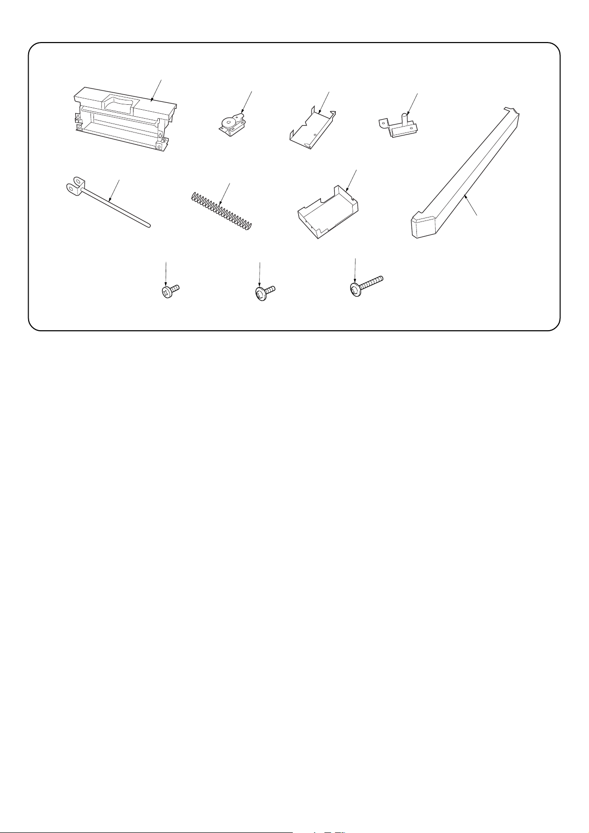
Supplied parts
A FEED IN UNIT ASS’Y......................................... 1
B FEED IN DRIVE ASS’Y ...................................... 1
C SUPPORT PLATE FEED IN COVER ASS’Y ..... 1
D FULCRUM PLATE, EJECT SUPPORT.............. 1
E SHAFT, EJECT SUPPORT ................................ 1
F FIXING UNIT RELEASE SPRING...................... 1
G REAR COVER, FEED IN.................................... 1
H FRONT COVER, FEED IN ................................. 1
J BINDING SCREW BVM4 × 6 (BLACK) .............. 5
K TRIPLE SCREW M4 × 6 (CHROMIUM) ............. 3
L TRIPLE SCREW M4 × 14 (CHROMIUM) ........... 4
K
L
3
1
Page 4
1
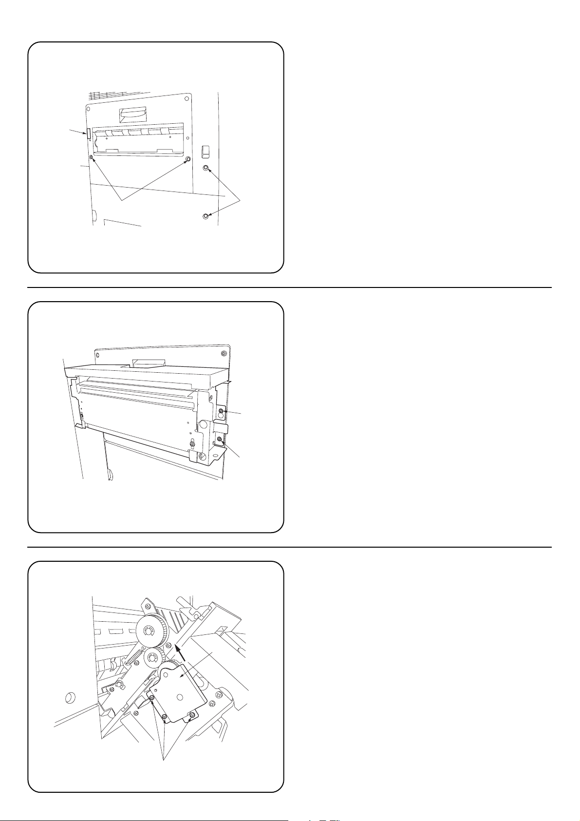
Before installation preparation
1. Cut one part 1 of the back side of the eject cover using nipper.
2. Remove fixing screw 2 (TRIPLE SCREW M4 × 6 CHROMIUM) 1
each from machine left middle cover and left lower cover.
3. Remove lower 2 fixing screw 3 (TRIPLE SCREW M4 × 12
CHROMIUM) of machine eject cover.
3
2
The installation procedure of the kit
1. Screw lightly TRIPLE SCREW M4 × 14 (CHROMIUM) L 2 screw to
the screw hole of the machine eject cover.
Hang FEED IN UNIT ASS’Y A to TRIPLE SCREW
M4 × 14 (CHROMIUM) L and tighten L.
2. Fix the lower side of FEED IN UNIT ASS’Y A to the eject cover with
the 2 screw 4 which you removed in procedure 3.
L
4
3. Fix FEED IN DRIVE ASS’Y B to the back side of FEED IN UNIT
ASS’Y A with 3 screw BINDING SCREW BVM4 × 6 (BLACK) J.
(Fix to the → direction)
B
J
4
2
Page 5

G
4. Fix REAR COVER, FEED IN G with 3 screws TRIPLE SCREW M4
× 6 (CHROMIUM) K.
K
5. Fix SUPPORT PLATE FEED IN COVER ASS’Y C to the machine
with 2 screws, TRIPLE SCREW M4 × 14 (CHROMIUM) L.
C
L
6. Attach FIXING UNIT RELEASE SPRING F to SHAFT, EJECT
SUPPORT E, then attach SHAFT, EJECT SUPPORT E to
FULCRUM PLATE, EJECT SUPPORT D.
D
F
E
5
3
Page 6

5
7. Insert the top of SHAFT, EJECT SUPPORT E to the hole FRONT
FRAME, FEED IN 5, and push SHAFT, EJECT SUPPORT E
upward to insert the pin of FULCRUM PLATE, EJECT SUPPORT D
to 6 round hole of SUPPORT PLATE FEED IN COVER ASS’Y C
and fix with 2 screws, BINDING SCREW BVM4 × 6 (BLACK) J.
6
J
8. Fix the Fixing plate 7 in the finisher kit to FEED IN UNIT ASS’Y with
4 screws 8 TP-A chrome screw M4 × 6 in the finisher kit. Fix so that
the position is a the middle.
8
7
8
H
9. Fix FRONT COVER, FEED IN H to SUPPORT PLATE FEED IN
COVER ASS’Y C with 2 screws 9 which you removed at (Before
installation preparation) 2nd procedure.
10. Fix FRONT COVER, FEED IN H together with the screw which fixes
rail unit to the machine.
9
6
4
Page 7

Initial position (stanard)
11. Install finisher.
12. Make some test copy.
13. When paper jam occurs in the finisher, or the paper is curled
downward much in the finisher, adjust by following the procedure on
the next page.
(machine front side of Feed in unit assy)
*Parts necessary to remove before adjusting
B FEED IN DRIVE ASS’Y, G REAR COVER,FEED IN
[ex.] The paper is curled downward.
the progress direction of the paper
image
(machine backside of Feed in unit assy)
7
5
Page 8

Fig.1 Fig.2
!
0
!
@
@
!
0
0
(machine front side of
Feed in unit assy)
If the paper ejected is curled downward much toward the image.
Of the 2 screws, remove one ! at the front side and loosen the other
0. Next, move the pin ← direction, and fix to the screw position @
(long hole) with the screw ! you removed.
(machine backside of
Feed in unit assy)
!
(machine front side of
Feed in unit assy)
If the paper is curled downward toward the image and the
procedure as shown in Fig.1 is inadequate.
Of the 2 screws, remove one ! at the front side and loosen the other
0. Next, move the pin → direction, and fix the position to the screw
! hole with the screw you removed.
(machine backside of
Feed in unit assy)
0
(Note)
It is not necessary to install the GUIDE, FEED IN AUXILIARY N
1 included in the finisher kit.
• •
8
6
Page 9

MEMO:
9
Page 10

MEMO:
Page 11

MEMO:
Page 12

2000. 10
2A080041B
 Loading...