

Page 1

F-2205/AD-62
Page 2

CONTENTS
1-1 Specifications
1-1-1 Specifications ....................................................................................................................................... 1-1-1
1-1-2 Part names and their functions ............................................................................................................ 1-1-2
(1) Finisher ......................................................................................................................................... 1-1-2
(2) Duplex unit .................................................................................................................................... 1-1-3
1-1-3 Machine cross section .......................................................................................................................... 1-1-4
(1) Finisher ......................................................................................................................................... 1-1-4
(2) Duplex unit .................................................................................................................................... 1-1-5
1-1-4 Drive system ........................................................................................................................................ 1-1-6
(1) Finisher ......................................................................................................................................... 1-1-6
(2) Duplex unit .................................................................................................................................... 1-1-7
1-2 Installation
1-2-1 Unpacking ............................................................................................................................................ 1-2-1
1-3 Troubleshooting
1-3-1 Paper misfeed detection ...................................................................................................................... 1-3-1
(1) Paper misfeed indication ............................................................................................................... 1-3-1
(2) Paper misfeed detection condition ................................................................................................ 1-3-2
(2-1) Finisher ................................................................................................................................. 1-3-2
(2-2) Duplex unit ........................................................................................................................... 1-3-3
(3) Paper misfeeds ............................................................................................................................. 1-3-4
(3-1) Finisher ................................................................................................................................. 1-3-4
(1) Paper jams in the finisher when the main switch is turned on. ..................................... 1-3-4
(2) Paper jams in the finisher during copying (jam during paper conveying for
batch ejection 1). ........................................................................................................... 1-3-4
(3) Paper jams in the finisher during copying (jam during paper conveying for
batch ejection 2). ........................................................................................................... 1-3-4
(3-2) Duplex unit ........................................................................................................................... 1-3-5
(1) Paper jams in the duplex unit when the main switch is turned on. ............................... 1-3-5
(2) Paper jams in the feedshift section during copying (jam in feedshift section). .............. 1-3-5
(3) Paper jams in the duplex unit during copying (jam in duplex paper
conveying section 1). .................................................................................................... 1-3-5
(4) Paper jams in the duplex unit during copying (jam in duplex paper
conveying section 2). .................................................................................................... 1-3-5
1-3-2 Self-diagnosis ....................................................................................................................................... 1-3-6
(1) Self-diagnostic function ................................................................................................................. 1-3-6
(2) Self-diagnostic codes .................................................................................................................... 1-3-7
1-3-3 Electrical problems ............................................................................................................................... 1-3-9
(1) Finisher ......................................................................................................................................... 1-3-9
(1) The paper conveying motor does not operate. ...................................................................... 1-3-9
(2) The feedshift solenoid does not operate. .............................................................................. 1-3-9
(3) The switchback solenoid does not operate. .......................................................................... 1-3-9
(4) The pickup solenoid does not operate. .................................................................................. 1-3-9
(5) The front side registration motor does not operate. ............................................................... 1-3-9
(6) Rear side registration motor does not operate. ..................................................................... 1-3-9
(7) Trailing edge registration motor does not operate. .............................................................. 1-3-10
(2) Duplex unit .................................................................................................................................. 1-3-11
(1) The duplex feedshift solenoid does not operate. ................................................................. 1-3-11
1-3-4 Mechanical problems ......................................................................................................................... 1-3-12
(1) Finisher ....................................................................................................................................... 1-3-12
(1) Paper jams. ......................................................................................................................... 1-3-12
(2) Abnormal noise is heard. ..................................................................................................... 1-3-12
(2) Duplex unit .................................................................................................................................. 1-3-13
(1) Paper jams. ......................................................................................................................... 1-3-13
(2) Abnormal noise is heard. ..................................................................................................... 1-3-13
1-1-1
3BN/3A4
Page 3

3BN/3A4
1-4 Assembly and Disassembly
1-4-1 Precautions for assembly and disassembly ......................................................................................... 1-4-1
(1) Precautions ................................................................................................................................... 1-4-1
1-4-2 Finisher ................................................................................................................................................ 1-4-2
(1) Adjusting the positions of the front side registration cursor, rear side registration cursor
and trailing edge registration cursor (reference) ........................................................................... 1-4-2
(2) Cleaning the stapler ...................................................................................................................... 1-4-3
(3) Adjusting the tension of the front and rear side registration belts ................................................. 1-4-4
1-4-3 Duplex unit ........................................................................................................................................... 1-4-5
(1) Adjusting the margin for printing ................................................................................................... 1-4-5
(2) Adjusting the amount of slack at the registration roller ................................................................. 1-4-6
(3) Adjusting the center line of image printing .................................................................................... 1-4-7
2-1 Mechanical construction
2-1-1 Feedshift section .................................................................................................................................. 2-1-1
(1) Paper conveying operation in sort mode ...................................................................................... 2-1-2
(2) Switchback operation in duplex mode .......................................................................................... 2-1-3
2-1-2 Intermediate tray section ...................................................................................................................... 2-1-4
(1) Paper registration on the intermediate tray ................................................................................... 2-1-5
2-1-3 Eject section ......................................................................................................................................... 2-1-6
2-1-4 Stapler section ..................................................................................................................................... 2-1-7
2-1-5 Duplex unit ........................................................................................................................................... 2-1-8
(1) Switching the paper path in the duplex unit .................................................................................. 2-1-9
2-2 Electrical Parts Layout
2-2-1 Electrical parts layout ........................................................................................................................... 2-2-1
(1) Finisher ......................................................................................................................................... 2-2-1
(2) Duplex unit .................................................................................................................................... 2-2-4
2-3 Operation of the PCBs
2-3-1 Main PCB ............................................................................................................................................. 2-3-1
2-4 Appendixes
Timing chart No. 1 ........................................................................................................................................... 2-4-1
Timing chart No. 2 ........................................................................................................................................... 2-4-2
Timing chart No. 3 ........................................................................................................................................... 2-4-3
Timing chart No. 4 ........................................................................................................................................... 2-4-4
Periodic maintenance procedure .................................................................................................................... 2-4-5
Wiring diagram ................................................................................................................................................ 2-4-6
1-1-2
Page 4

1-1-1 Specifications
3BN/3A4
Finisher
Type ............................................... Built-in
Number of trays.............................. 1 (intermediate tray)
1
Stapling limit ................................... A4/11" × 8
/2" or smaller: 30 sheets
Other sizes than above: 20 sheets
Power source ................................. Electrically connected to the copier
Dimensions .................................... 696 (W) × 618 (D) × 281 (H) mm
273/8" (W) × 245/16" (D) × 111/16" (H)
Weight ............................................ Approximately 11 kg/24.2 lbs
Duplex unit
Type ............................................... Outboard
Paper ..............................................Plain paper: 75 – 80 g/m
2
Special paper: colored paper
1
Paper sizes .................................... A3 – A5R, folio/11" × 17" – 5
/2" × 81/2"
Power source ................................. Electrically connected to the copier
Dimensions .................................... 48 (W) × 450 (D) × 397 (H) mm
1
/8" (W) × 1711/16" (D) × 155/8" (H)
1
Weight ............................................Approximately 3.3 kg/7.26 lbs
1-1
1-1-1
Page 5

3BN/3A4
1-1-2 Part names and their functions
1-1
(1) Finisher
4
3
2
1
Figure 1-1-1
1 Intermediate tray
2 JAM release lever
3 Stapler
4 Eject tray
1-1-2
Page 6

(2) Duplex unit
3BN/3A4
1-1
2
1
Figure 1-1-2
1 Duplex lever
2 Open/close guide
1-1-3
Page 7
3BN/3A4
1-1-3 Machine cross section
1-1
(1) Finisher
31 2
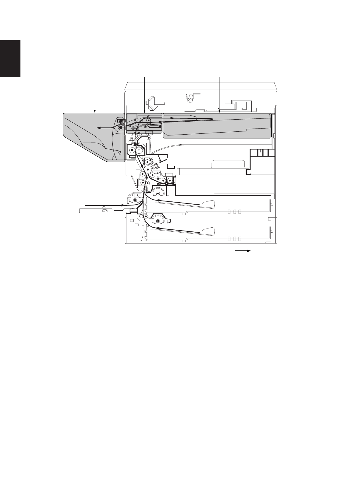
Figure 1-1-3 Machine cross section (finisher)
1 Feedshift section
2 Intermediate tray section
3 Eject section
Paper path
1-1-4
Page 8

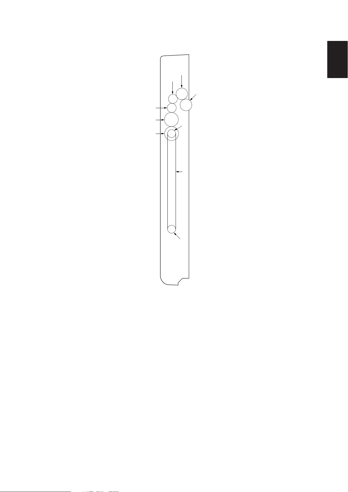
(2) Duplex unit
3BN/3A4
1-1
Figure 1-1-4 Machine cross section (duplex unit)
Paper path
1-1-5
Page 9

3BN/3A4
1-1-4 Drive system
1-1
(1) Finisher
(
*
%$# 43 67 8
^
5
9
&2 @1!0
Figure 1-1-5
1 Paper conveying motor gear
2 Gear 18/38
3 Gear 18
4 Central gear
5 Gear 15
6 Central gear (front)
7 Gear 21 (rear)
8 Lift clutch gear
9 Clutch cam
0 Stopper gear
! Gear 32
@ Stopper gear 26
# One-way gear 18 (rear)
$ Gear 21 (front)
% Central gear (middle)
^ Gear 25
& Gear 18
* Gear 16
( Gear 25
1-1-6
Page 10
(2) Duplex unit
3BN/3A4
1-1
2
3
1
4
5
6
7
8
9
1 Gear 20
2 Gear 20
3 Gear 16
4 Gear 16
5 Gear 25
Figure 1-1-5
6 Gear 25
7 Pulley 20
8 Duplex belt
9 Pulley 20
1-1-7
Page 11

1-2-1 Unpacking
„
¤
2
3BN/3A4
%
‹
6
fi
^
&
⁄
1
(
*
›
fl
‡
3
‚
@
7
8
$
9
·
4
Œ
)
#
5
1-2
0
!
°
›
Figure 1-2-1 Unpacking (finisher)
1 Intermediate tray unit
2 Feedshift unit
3 Eject unit
4 Eject tray unit
5 Stapler cover
6 Staple cartridge
7 Upper paper conveying cover F
8 Upper eject cover F
9 Upper eject cover D
0 Two (2) cross-head bronze binding screws BVM3 × 05
! Two (2) cross-head chrome TP-A screws M3 × 05
@ Installation manual
# Instruction handbook
$ Plastic bag
% Unit spacer
^ Cursor spacer
& Outer case
* Eject tray spacer
( Spacer B
) Spacer C
⁄ Intermediate tray pad
¤ Stapler pad
‹ Cover pad
› Bar-code labels
fi Plastic sheet
fl Product cover
‡ Air-padded bag
— Plastic bag
· Air-padded bag
‚ Plastic bag
ΠPlastic bag
„ Plastic bag
1-2-1
Page 12

3BN/3A4
^
1-2
7
(
⁄
¤
2
(
%
)
&
$
%
90!
@#*
‹
4
1
¤
$
6
35
8
Figure 1-2-2 Unpacking (duplex unit)
1 Duplex unit
2 Duplex joint
3 Front duplex fulcrum plate
4 Rear duplex fulcrum plate
5 Front fulcrum hook
6 Duplex stopper
7 Left cover
8 Entry guide
9 Two (2) stoppers 5
0 Seven (7) cross-head chrome binding screws
M3 × 14
! One (1) cross-head chrome TP-A screw M3 × 05
@ One (1) cross-head tap-tight P chrome TP-A screw
M3 × 08
# One (1) cross-head tap-tight P chrome TP-A screw
M4 × 12
$ Bottom pads
% Spacers
^ Upper pad
& Outer case
* Plastic bag
( Plastic bag
) Product cover
⁄ Air-padded bag
¤ Bar-code label
‹ Air-padded bag
1-2-2
Page 13

3BN/3A4
1-3-1 Paper misfeed detection
(1) Paper misfeed indication
When paper jams, the machine immediately stops operation and the occurrence of a paper jam is indicated on the copier
operation panel.
To remove the jammed paper, lower the intermediate tray or open the duplex unit.
To reset the paper misfeed detection, detach and refit the intermediate tray to turn the tray open/close switch off and on or
open and close the duplex unit to turn the duplex open/close switch off and on.
DUPPCSW1
PCSW
1-3
DUPPCSW2
RSW
Figure 1-3-1 Paper misfeed detection
1-3-1
Page 14

1-3
3BN/3A4
(2) Paper misfeed detection condition
(2-1) Finisher
• Jam between the finisher and copier (jam code 80)
No signal indicating the completion of paper ejection is output from the finisher within 15 s of the paper conveying switch
(PCSW) turning off.
• Jam during batch ejection standby (jam code 81)
No signal requesting batch ejection is output from the finisher within 15 s of the ejection of the last sheet to the
intermediate tray.
• Jam during paper conveying for batch ejection 1 (jam code 82)
When ejecting a stack of paper, the paper conveying switch (PCSW) does not turn on within 1250 ms of the start of forward
rotation of the paper conveying motor (PCM).
PCM
PCSW
Fwd. rotation
1250 ms
Off
On
Off
On
Timing chart 1-3-1
When ejecting a stack of paper, the paper conveying switch (PCSW) does not turn off within 6320 ms of turning on.
PCSW
6320 ms
Off
On
Timing chart 1-3-2
• Jam during paper conveying for batch ejection 2 (jam code 83)
When ejecting a stack of paper, duplex paper conveying switch 1 (DUPPCSW1) does not turn on within 1250 ms of the
paper conveying switch (PCSW) turning on.
PCSW
DUPPCSW1
1250 ms
Off
On
Off
On
Timing chart 1-3-3
When ejecting a stack of paper, duplex paper conveying switch 1 (DUPPCSW1) does not turn off within 1640 ms of turning
on.
DUPPCSW1
1640 ms
Off
On
Timing chart 1-3-4
1-3-2
Page 15

3BN/3A4
(2-2) Duplex unit
• Jam in feedshift section (jam code 51)
Duplex paper conveying switch 1 (DUPPCSW1) does not turn on within 1640 ms of the start of reverse rotation of the
paper conveying motor (PCM).
PCM
DUPPCSW1
Rev. rotation
1640 ms
Off
On
Off
On
Timing chart 1-3-5
• Jam in duplex paper conveying section 1 (jam code 60)
Duplex paper conveying switch 2 (DUPPCSW2) does not turn on within 3360 ms of duplex paper conveying switch 1
(DUPPCSW1) turning on.
DUPPCSW1
DUPPCSW2
3360 ms
Off
On
Off
On
Timing chart 1-3-6
• Jam in duplex paper conveying section 2 (jam code 61)
Duplex paper conveying switch 2 (DUPPCSW2) does not turn off within 3360 ms of duplex paper conveying switch 1
(DUPPCSW1) turning off.
DUPPCSW1
DUPPCSW2
3360 ms
Off
On
Off
On
1-3
Timing chart 1-3-7
The registration switch (RSW) of the copier does not turn on within 3300 ms of duplex paper conveying switch 2
(DUPPCSW2) turning on.
DUPPCSW2
RSW (copier)
3300 ms
Off
On
Off
On
Timing chart 1-3-8
1-3-3
Page 16

1-3
3BN/3A4
(3) Paper misfeeds
(3-1) Finisher
Problem Causes Check procedures/corrective measures
(1)
Paper jams in the
finisher when the
main switch is turned
on.
(2)
Paper jams in the
finisher during
copying (jam during
paper conveying for
batch ejection 1).
(3)
Paper jams in the
finisher during
copying (jam during
paper conveying for
batch ejection 2).
A piece of paper torn from
copy paper is caught
around the paper
conveying switch.
Defective paper conveying
switch.
Defective paper conveying
switch.
Check if the feedshift roller
or press roller is deformed.
Defective duplex paper
conveying switch 1 in the
duplex unit.
Check if the eject pulley or
eject roller is deformed.
Remove any found.
With 5 V DC present at CN4-9 on the main PCB, check if CN4-10
on the main PCB remains low when the paper conveying switch
is turned on and off. If it does, replace the paper conveying
switch.
With 5 V DC present at CN4-9 on the main PCB, check if CN4-10
on the main PCB remains high or low when the paper conveying
switch is turned on and off. If it does, replace the paper
conveying switch.
Check visually and replace the pulley or roller if deformed.
With 5 V DC present at CN5-11 on the copier main PCB, check if
CN5-10 on the copier main PCB remains high or low when
duplex paper conveying switch 1 is turned on and off. If it does,
replace duplex paper conveying switch 1.
Check visually and replace the pulley or roller if deformed.
1-3-4
Page 17

(3-2) Duplex unit
Problem Causes Check procedures/corrective measures
(1)
Paper jams in the
duplex unit when the
main switch is turned
on.
A piece of paper torn from
copy paper is caught
around duplex paper
conveying switch 1 or 2.
Defective duplex paper
conveying switch 1.
Remove any found.
With 5 V DC present at CN5-11 on the copier main PCB, check if
CN5-10 on the main PCB remains low when duplex paper
conveying switch 1 is turned on and off. If it does, replace duplex
paper conveying switch 1.
3BN/3A4
(2)
Paper jams in the
feedshift section
during copying (jam
in feedshift section).
(3)
Paper jams in the
duplex unit during
copying (jam in
duplex paper
conveying section 1).
(4)
Paper jams in the
duplex unit during
copying (jam in
duplex paper
conveying section 2).
Defective duplex paper
conveying switch 2.
Defective duplex paper
conveying switch 1.
Check if the feedshift pulley
or feedshift roller is
deformed.
Defective duplex paper
conveying switch 2.
Check if the duplex roller or
upper duplex roller is
deformed.
Defective duplex paper
conveying switch 2.
Defective copier
registration switch.
Check if the duplex pulley
or lower duplex roller is
deformed.
With 5 V DC present at CN5-8 on the copier main PCB, check if
CN5-7 on the main PCB remains low when duplex paper
conveying switch 2 is turned on and off. If it does, replace duplex
paper conveying switch 2.
With 5 V DC present at CN5-11 on the copier main PCB, check if
CN5-10 on the main PCB remains high when duplex paper
conveying switch 1 is turned on and off. If it does, replace duplex
paper conveying switch 1.
Check visually and replace the pulley or roller if deformed.
With 5 V DC present at CN5-8 on the copier main PCB, check if
CN5-7 on the main PCB remains high when duplex paper
conveying switch 2 is turned on and off. If it does, replace duplex
paper conveying switch 2.
Check visually and replace the pulley or roller if deformed.
With 5 V DC present at CN5-8 on the copier main PCB, check if
CN5-7 on the main PCB remains low when duplex paper
conveying switch 2 is turned on and off. If it does, replace duplex
paper conveying switch 2.
With 5 V DC present at CN3-6 on the copier main PCB, check if
CN3-7 on the main PCB remains high when the registration
switch is turned on and off. If it does, replace the registration
switch.
Check visually and replace the pulley or roller if deformed.
1-3
1-3-5
Page 18

1-3
3BN/3A4
1-3-2 Self-diagnosis
(1) Self-diagnostic function
This unit is equipped with a self-diagnostic function. When a problem is detected, copying is disabled and the problem
displayed as a code consisting of “C” followed by a number between 034 and 821, indicating the nature of the problem.
A message is also displayed requesting the user to call for service.
After removing the problem, the self-diagnostic function can be reset by turning the tray open/close switch or copier safety
switch 1, 2 or 3 off and back on.
1-3-6
Page 19

(2) Self-diagnostic codes
3BN/3A4
Code Contents
C034 Finisher communication problem
During the serial communication
between the copier and finisher, when
there is no reply to the command from
the copier from the finisher, serial
communication does not recover after
5 retries.
C817 Front side registration motor problem
When the side registration front home
position sensor is on during initialization,
the sensor does not turn off within
570 ms of the start of initialization.
When the side registration front home
position sensor is off during initialization,
the sensor does not turn on within
3180 ms of the start of initialization.
Remarks
Causes Check procedure/corrective measures
The connector
makes poor
contact.
Defective copier
main PCB.
Defective finisher
main PCB.
The front side
registration motor
connector makes
poor contact.
Defective front
side registration
motor.
The side registration front home
position sensor
connector makes
poor contact.
Defective side
registration front
home position
sensor.
Check the connection of connector CN27
on the copier main PCB and CN1 on the
finisher main PCB, and the continuity
across the connector terminals. Remedy or
replace if necessary.
Replace the copier main PCB and check for
correct operation.
Replace the finisher main PCB and check
for correct operation.
Reinsert the connector. Also check for
continuity within the connector cable. If
none, repair or replace the cable.
Replace the front side registration motor
and check for correct operation.
Reinsert the connector. Also check for
continuity within the connector cable. If
none, repair or replace the cable.
Replace the side registration front home
position sensor and check for correct
operation.
1-3
C818 Rear side registration motor problem
When the side registration rear home
position sensor is on during initialization,
the sensor does not turn off within
570 ms of the start of initialization.
When the side registration rear home
position sensor is off during initialization,
the sensor does not turn on within
2880 ms of the start of initialization.
Defective finisher
main PCB.
The rear side
registration motor
connector makes
poor contact.
Defective rear side
registration motor.
The side registration rear home
position sensor
connector makes
poor contact.
Defective side
registration rear
home position
sensor.
Defective finisher
main PCB.
Replace the finisher main PCB and check
for correct operation.
Reinsert the connector. Also check for
continuity within the connector cable. If
none, repair or replace the cable.
Replace the rear side registration motor and
check for correct operation.
Reinsert the connector. Also check for
continuity within the connector cable. If
none, repair or replace the cable.
Replace the side registration rear home
position sensor and check for correct
operation.
Replace the finisher main PCB and check
for correct operation.
1-3-7
Page 20

3BN/3A4
1-3
Code Contents
C819 Trailing edge registration motor
problem
When the trailing edge registration
home position sensor is on during
initialization, the sensor does not turn off
within 570 ms of the start of initialization.
When the trailing edge registration
home position sensor is off during
initialization, the sensor does not turn on
within 4550 ms of the start of
initialization.
C821 Stapler motor problem
When the stapler home position sensor
is off during stapler initialization, the
sensor does not turn on within 600 ms
of the start of the stapler motor forward
rotation and then it fails to turn on again
within 600 ms of the start of the stapler
motor reverse rotation.
The stapler home position sensor does
not turn off within 200 ms of the start of
stapling.
During stapling, the stapler home
position sensor does not turn on within
600 ms of turning off.
The stapler home position sensor does
not turn off within 200 ms of the start of
self-priming.
During self-priming, the stapler home
position sensor does not turn on within
600 ms of turning off.
Remarks
Causes Check procedure/corrective measures
The trailing edge
registration motor
connector makes
poor contact.
Defective trailing
edge registration
motor.
The trailing edge
registration home
position sensor
connector makes
poor contact.
Defective trailing
edge registration
home position
sensor.
Defective finisher
main PCB.
The stapler motor
connector makes
poor contact.
The stapler
malfunctions.
a) The stapler is
blocked with a
staple.
b) The stapler is
broken.
Defective finisher
main PCB.
Reinsert the connector. Also check for
continuity within the connector cable. If
none, repair or replace the cable.
Replace the trailing edge registration motor
and check for correct operation.
Reinsert the connector. Also check for
continuity within the connector cable. If
none, repair or replace the cable.
Replace the trailing edge registration home
position sensor and check for correct
operation.
Replace the finisher main PCB and check
for correct operation.
Reinsert the connector. Also check for
continuity within the connector cable. If
none, repair or replace the cable.
a) Remove the staple cartridge and check
the cartridge and the stapling section of
the stapler.
b) Replace the stapler and check for correct
operation.
Replace the finisher main PCB and check
for correct operation.
1-3-8
Page 21

1-3-3 Electrical problems
(1) Finisher
Problem Causes Check procedures/corrective measures
(1)
The paper conveying
motor does not
operate.
Broken paper conveying
motor coil.
Poor contact of the paper
conveying motor connector
terminals.
Check for continuity across the coil. If none, replace the paper
conveying motor.
Reinsert the connector. Also check for continuity within the
connector cable. If none, remedy or replace the cable.
3BN/3A4
(2)
The feedshift
solenoid does not
operate.
(3)
The switchback
solenoid does not
operate.
(4)
The pickup solenoid
does not operate.
Defective finisher main
PCB.
Broken feedshift solenoid
coil.
Poor contact of the
feedshift solenoid
connector terminals.
Defective finisher main
PCB.
Broken switchback
solenoid coil.
Poor contact of the
switchback solenoid
connector terminals.
Defective finisher main
PCB.
Broken pickup solenoid
coil.
Poor contact of the pickup
solenoid connector
terminals.
Defective finisher main
PCB.
Check if a motor drive coil energization signal is output at CN9-9,
CN9-10, CN9-11 and CN9-12 on the finisher main PCB. If not,
replace the finisher main PCB.
Check for continuity across the coil. If none, replace the feedshift
solenoid.
Reinsert the connector. Also check for continuity within the
connector cable. If none, remedy or replace the cable.
Check if CN4-2 and CN4-4 on the finisher main PCB go low. If
not, replace the finisher main PCB.
Check for continuity across the coil. If none, replace the
switchback solenoid.
Reinsert the connector. Also check for continuity within the
connector cable. If none, remedy or replace the cable.
Check if CN4-6 and CN4-8 on the finisher main PCB go low. If
not, replace the finisher main PCB.
Check for continuity across the coil. If none, replace the pickup
solenoid.
Reinsert the connector. Also check for continuity within the
connector cable. If none, remedy or replace the cable.
Check if CN4-7 on the finisher main PCB goes low. If not, replace
the finisher main PCB.
1-3
(5)
The front side
registration motor
does not operate.
(6)
Rear side
registration motor
does not operate.
Broken front side
registration motor coil.
Poor contact of the front
side registration motor
connector terminals.
Defective finisher main
PCB.
Broken rear side
registration motor coil.
Poor contact of the rear
side registration motor
connector terminals.
Defective finisher main
PCB.
Check for continuity across the coil. If none, replace the front side
registration motor.
Reinsert the connector. Also check for continuity within the
connector cable. If none, remedy or replace the cable.
Check if a motor drive coil energization signal is output at CN5-1,
CN5-3, CN5-4 and CN5-5 on the finisher main PCB. If not,
replace the finisher main PCB.
Check for continuity across the coil. If none, replace the rear side
registration motor.
Reinsert the connector. Also check for continuity within the
connector cable. If none, remedy or replace the cable.
Check if a motor drive coil energization signal is output at CN5-6,
CN5-8, CN5-9 and CN5-10 on the finisher main PCB. If not,
replace the finisher main PCB.
1-3-9
Page 22

3BN/3A4
Problem Causes Check procedures/corrective measures
(7)
Trailing edge
registration motor
does not operate.
Broken trailing edge
registration motor coil.
Poor contact of the trailing
edge registration motor
connector terminals.
Check for continuity across the coil. If none, replace the trailing
edge registration motor.
Reinsert the connector. Also check for continuity within the
connector cable. If none, remedy or replace the cable.
1-3
Defective finisher main
PCB.
Check if a motor drive coil energization signal is output at CN6-1,
CN6-2, CN6-3 and CN6-4 on the finisher main PCB. If not,
replace the finisher main PCB.
1-3-10
Page 23

(2) Duplex unit
Problem Causes Check procedures/corrective measures
(1)
The duplex feedshift
solenoid does not
operate.
Broken duplex feedshift
solenoid coil.
Poor contact of the duplex
feedshift solenoid
connector terminals.
Check for continuity across the coil. If none, replace the duplex
feedshift solenoid.
Reinsert the connector. Also check for continuity within the
connector cable. If none, remedy or replace the cable.
3BN/3A4
Defective copier main PCB.
Run maintenance item U033 and check if CN5-3 and CN5-4 on
the copier main PCB go low. If not, replace the main PCB.
1-3
1-3-11
Page 24

3BN/3A4
1-3-4 Mechanical problems
(1) Finisher
Problem Causes/check procedures Corrective measures
(1)
Paper jams.
Check if the contact between the feedshift
pulley and feedshift roller is correct.
Check and remedy.
1-3
(2)
Abnormal noise is
heard.
Check if the contact between the feedshift
roller and press roller is correct.
Check if the rollers and gears operate
smoothly.
Check and remedy.
Grease the bushings and gears.
1-3-12
Page 25

(2) Duplex unit
Problem Causes/check procedures Corrective measures
(1)
Paper jams.
Check if the duplex pulley, upper duplex roller
or lower duplex roller is deformed.
3BN/3A4
Check visually and replace the pulley or
roller if deformed.
(2)
Abnormal noise is
heard.
Check if rollers and gears operate smoothly.
Apply grease to the bushings and gears.
1-3
1-3-13
Page 26

1-4-1 Precautions for assembly and disassembly
(1) Precautions
• Be sure to turn the main switch off and disconnect the power plug before starting disassembly.
• When handling PCBs, do not touch connectors with bare hands or damage the board.
• Do not touch any PCB containing ICs with bare hands or any object prone to static charge.
• Use the following testers when measuring voltages:
Hioki 3200
Sanwa MD-180C
Sanwa YX-360TR
Beckman TECH300
Beckman DM45
Beckman 330*
Beckman 3030*
Beckman DM850*
Fluke 8060A*
Arlec DMM1050
Arlec YF1030C
* Capable of measuring RMS values.
• Prepare the following as test originals:
1. NTC (new test chart)
2. NPTC (newspaper test chart)
3BN/3A4
1-4
1-4-1
Page 27

3BN/3A4
Stapler
5 ± 2.5 mm
5 ± 2.5 mm
1-4-2 Finisher
(1) Adjusting the positions of the front side registration cursor, rear side registration cursor and trailing edge
registration cursor (reference)
Perform the following adjustment if paper registration is poor or stapling is made outside the specified area.
Procedure
Start
Make a test copy
in staple-sort mode.
1-4
Is the paper registration
good?
Yes
Is the stapling
position correct?
See Figure 1-4-1.
Yes
End
No
No
Enter maintenance mode.
Enter 246 using the numeric
keys.
Press the start key.
Select the item to be adjusted
using the cursor up/down keys.
Change the setting using the
cursor left/right keys.
Press the start key.
The new setting
is stored.
Press the stop/clear key.
Figure 1-4-1 Stapling position
ADJUST FRONT JOGGER: Stop position of the
front side registration cursor
ADJUST REAR JOGGER: Stop position of the rear
side registration cursor
ADJUST END JOGGER: Stop position of the
trailing edge registration cursor
Setting range: 0 to 8
Reference: 4
Increasing the value moves the front or rear side
registration cursor or trailing edge registration
cursor outward (a); decreasing the value moves
each cursor inward (e). See Figure 1-4-2.
1-4-2
Exit maintenance mode.
Rear side registration cursor
Trailing edge
registration cursor
Front side
registration cursor
Figure 1-4-2
Page 28

(2) Cleaning the stapler
During periodic maintenance, remove all the staples remaining inside the machine due to failure of stapling.
Procedure
1. Open the front cover of the copier.
2. Remove the staple cartridge.
3. Remove the screw securing the stapler cover
and then the cover.
4. Remove the staples attracted to the magnet on
the inside of the stapler cover.
5. Refit all the removed parts.
Magnet
Staple
3BN/3A4
1-4
Stapler cover
Staple cartridge
Figure 1-4-3
1-4-3
Page 29

1-4
3BN/3A4
(3) Adjusting the tension of the front and rear side registration belts
Adjust the tension of each belt during periodic maintenance.
Procedure
1. Remove the intermediate tray unit from the
copier.
2. Loosen the tension adjustment screws for the
front and rear side registration belts. The
tension of the tension spring will be applied to
the belts.
3. Retighten the screws. Each belt will be
secured with the tension applied.
For adjusting the tension of
the rear side registration belt
Intermediate tray unit
For adjusting the tension
of the front side
registration belt
Figure 1-4-4
1-4-4
Page 30

3BN/3A4
Printer leading edge margin
for duplex copying
(second face, 3 ± 2.5 mm)
1-4-3 Duplex unit
(1) Adjusting the margin for printing
Perform the following adjustment if the printer leading edge margin for duplex copying (second face) is not correct.
Procedure
Start
Enter maintenance mode.
Enter “402” using the numeric
keys.
Press the start key.
Figure 1-4-5
Select “TRAIL 2” using the
cursor up/down keys.
1-4
Press the interrupt key.
Press the start key to
output a test pattern.
Is the margin correct?
Yes
Press the stop/clear key.
Exit maintenance mode.
End
Press the start key.
The new setting is stored.
No
Change the value using the
cursor left/right keys.
Setting range: –5.0 to +10.0
Reference: 4.5
Changing the value by 1 moves the margin by
0.5 mm.
Increasing the value makes the margin wider
and decreasing it makes the margin narrower.
1-4-5
Page 31

3BN/3A4
(2) Adjusting the amount of slack at the registration roller
Perform the following adjustment if the leading edge of the copy image is missing or varies randomly, or if the copy paper is
Z-folded during duplex copying.
Procedure
Start
Enter maintenance mode.
1-4
Enter “051” using the numeric
keys.
Press the start key.
Select “DUPLEX” using the
cursor up/down keys.
Press the interrupt key.
Make a test copy in duplex mode.
Is the leading
edge of the image missing
or varying randomly
(copy example 1)?
No
Is the copy paper
Z-folded (copy example 2)?
Yes
Yes
Press the start key.
The new setting is stored.
Increase the value using the
cursor right key.
Decrease the value using the
cursor left key.
Original Copy
example 1
Figure 1-4-6
Copy
example 2
No
Press the stop/clear key.
Exit maintenance mode.
End
Setting range: –50 to +50
Reference: 0
Changing the value by 1
changes the amount of slack
by 0.1 mm.
Initial setting: 0
The greater the value,
the larger the amount of slack;
the smaller the value,
the smaller the amount of slack
1-4-6
Page 32

3BN/3A4
(3) Adjusting the center line of image printing
Make the following adjustment if there is a regular error between the center lines of the copy image and original when
copying using the duplex unit.
Procedure
Start
Enter maintenance mode.
Enter “034” using
the numeric keys.
Press the start key.
Select “ADJ. LSU OUT TIMING”
using the cursor up/down keys
and press the start key.
Select “LSU DUP” using
the cursor up/down keys.
Press the interrupt key.
Press the start key to
output a test pattern.
Correct image Output
Press the start key.
The new setting is stored.
Center line of printing
example 1
Figure 1-4-7
Output
example 2
1-4
Is the image correct?
Yes
Press the stop/clear key
to exit maintenance mode.
End
For output example 1, decrease
the value using the cursor left key.
No
For output example 2, increase
the value using the cursor right
key.
Setting range: –5.0 to +5.0
Changing the value by 1 moves the
center line by 0.1 mm.
Initial setting: 0
1-4-7
Page 33

3BN/3A4
2-1-1 Feedshift section
The feedshift section consists of the components shown in Figure 2-1-1. It switches the path for the paper conveyed from
the copier in sort and duplex modes.
1
6
2
3
5
7
Figure 2-1-1 Feedshift section
1 Feedshift pulley
2 Feedshift roller
3 Press roller
4 Press roller lift
PCM
4
5 Stopper
6 Feedshift claw
7 Paper conveying switch (PCSW)
SBSOL
PCSW
FSSOL
2-1
PUSOL
CN6-7 –
CN6-12
CN4-10
CN4-2, 4
CN4-6, 8
MPCB
Figure 2-1-2 Feedshift section block diagram
CN4-7
2-1-1
Page 34

3BN/3A4
(1) Paper conveying operation in sort mode
When a copy is made in the sort mode, the feedshift solenoid (FSSOL) turns on and the feedshift guide of the copier
operates to switch the paper path to the feedshift section. The switchback solenoid (SBSOL) then turns on to lower the
separation claw and the paper is conveyed to the intermediate tray by the feedshift roller. When the trailing edge registration
cursor of the intermediate tray shifts the paper stocked in the intermediate tray to the stopper, the pickup solenoid (PUSOL)
turns on to lift the press roller and release the stopper, and the switchback solenoid (SBSOL) turns off to lift the feedshift
claw. The stack of paper on the intermediate tray is then ejected to the eject tray by the feedshift roller.
2-1
Feedshift claw
(SBSOL: ON)
Feedshift guide
(FSSOL: ON)
Feedshift claw
(SBSOL: OFF)
Feedshift pulley
To intermediate tray
Feedshift roller
Stocked paper
Press roller
Stopper (PUSOL: OFF)
Feedshift pulley
2-1-2
Feedshift roller
Press roller
Stopper (PUSOL: ON)
Figure 2-1-3
Page 35

3BN/3A4
(2) Switchback operation in duplex mode
In duplex mode, when the rear face of the paper is copied, the paper is conveyed to the feedshift section in the same
manner as in sort mode. When the trailing edge of the paper passes the paper conveying switch (PCSW), the paper
conveying motor (PCM) reverses, rotating the feedshift roller in the reverse direction to switch back the paper into the
duplex unit.
Feedshift roller
(PCM: Fwd. rotation)
PCSW: ON
PCSW: OFF
2-1
Feedshift roller
(PCM: Rev. rotation)
Figure 2-1-4
2-1-3
Page 36

3BN/3A4
2-1-2 Intermediate tray section
The intermediate tray section consists of the components shown in Figure 2-1-5. It stores and evens up the paper conveyed
from the feedshift section and returns the stack of paper to the feedshift section.
23
4
1
Figure 2-1-5 Intermediate tray section
2-1
1 Intermediate tray
2 Front side registration cursor
SRFHPS
FSRM
CN4-12
CN5-1 –
CN5-5
RSRM
CN5-6 –
Figure 2-1-6 Intermediate tray section block diagram
CN5-10
3 Rear side registration cursor
4 Trailing edge registration cursor
SRRHPS TERHPS
TERM
CN4-14
CN4-26
CN6-1 –
MPCB
CN6-4
2-1-4
Page 37

3BN/3A4
(1) Paper registration on the intermediate tray
In sort mode, the front and rear side registration cursors move to the size of the paper used to even up the sides of the stack
of paper and the trailing edge registration cursor shifts the paper to the feedshift section.
In staple-sort mode, the front and rear side registration cursors even up the sides of the stack of paper and shift the stack
toward the machine front, and then the trailing edge registration cursor shifts the stack to the stapling position.
Home positions
Rear side registration cursor
Trailing edge registration cursor
Front side
registration cursor
Paper registration
Shifting the paper to
the stapling position
2-1
Figure 2-1-7
2-1-5
Page 38

3BN/3A4
2-1-3 Eject section
The eject section consists of the components shown in Figure 2-1-8. It ejects paper to the eject tray.
2
2-1
1
3
Figure 2-1-8 Eject section
1 Eject tray
2 Eject pulley
4
3 Eject roller
4 Lower eject guide
2-1-6
Page 39

2-1-4 Stapler section
In staple-sort mode, paper stocked on the intermediate tray is stapled by the stapler.
The stapler motor (STM) drives the stapler cam via the stapler drive gear to staple paper.
3BN/3A4
Stapler self-priming
sensor
Figure 2-1-9 Stapler section
Stapler drive gear
Stapler cam
Stapler motor
Stapler cam
2-1
STES STCS
STHPS
STM
STSPS
Figure 2-1-10 Stapler section block diagram
CN4-20
CN4-22
CN4-16
CN6-13 –
CN6-16
CN4-24
MPCB
2-1-7
Page 40

2-1
3BN/3A4
2-1-5 Duplex unit
The duplex unit consists of the components shown in Figure 2-1-11. In duplex mode, it refeeds paper switched back in the
feedshift section to the copier paper feed section.
7
1
2
4
5
8
3
4
6
1 Duplex feedshift guide
2 Upper duplex roller
3 Lower duplex roller
4 Duplex pulley
Figure 2-1-12 Duplex unit block diagram
Figure 2-1-11 Duplex unit
5 Open/close guide
6 Entry guide
7 Duplex paper conveying switch 1 (DUPPCSW1)
8 Duplex paper conveying switch 2 (DUPPCSW2)
DUPPCSW1
CN5-10
DUPFSSOL
CN5-3, 4
DUPPCSW2
CN5-7
MPCB
(copier)
2-1-8
Page 41

3BN/3A4
(1) Switching the paper path in the duplex unit
In duplex mode, when the reverse face of the paper is copied, the paper is switched back in the feedshift section and
conveyed to the duplex unit. The paper is then conveyed to the paper conveying section of the copier by the upper and
lower duplex rollers.
When ejecting paper to the eject tray, the duplex feedshift solenoid (DUPFSSOL) turns on to operate the duplex feedshift
guide to switch the paper path to the eject tray.
Duplex feedshift guide
Eject tray
2-1
Figure 2-1-13
2-1-9
Page 42

2-2-1 Electrical parts layout
(1) Finisher
3BN/3A4
3
56
1
Machine front
2
Machine inside
4
Machine rear
Figure 2-2-1 Feedshift section
1. Left cover switch (LCSW) ............................ Detects if the copier left cover is opened or closed.
2. Paper conveying switch (PCSW) ................. Detects a paper jam in the finisher.
3. Paper conveying motor (PCM) .................... Drives the feedshift section.
4. Feedshift solenoid (FSSOL) ........................ Operates the feedshift guide of the copier.
5. Switchback solenoid (SBSOL) ..................... Operates the feedshift claw.
6. Pickup solenoid (PUSOL) ............................ Operates the press roller.
2-2
2-2-1
Page 43

3BN/3A4
6
2
8
7
5
4
3
1
9
2-2
Machine front Machine inside
Machine rear
Figure 2-2-2 Intermediate tray section
1. Main PCB (MPCB) ....................................... Controls electrical components.
2. Tray open/close switch (TOCSW) ................ Detects if the intermediate tray is opened or closed.
3. Intermediate tray sensor (ITS) ..................... Detects the presence of paper on the intermediate tray.
4. Side registration front home position
sensor (SRFHPS) ........................................ Detects the front side registration cursor in the home position.
5. Side registration rear home position
sensor (SRRHPS) ........................................ Detects the rear side registration cursor in the home position.
6. Trailing edge registration home position
sensor (TERHPS) ........................................ Detects the trailing edge registration cursor in the home position.
7. Front side registration motor (FSRM) .......... Drives the front side registration cursor.
8. Rear side registration motor (RSRM) .......... Drives the rear side registration cursor.
9. Trailing edge registration motor (TERM) ...... Drives the trailing edge registration cursor.
2-2-2
Page 44

3BN/3A4
2
1
3
5
4
Machine front Machine inside
Machine rear
Figure 2-2-3 Stapler section
1. Stapler empty sensor (STES) ...................... Detects the presence of staples.
2. Staple cartridge sensor (STCS) ................... Detects the presence of the staple cartridge.
3. Stapler home position sensor (STHPS) ....... Detects the stapler in the home position.
4. Stapler self-priming sensor (STSPS) ........... Detects the pre-stapling state of the stapler.
5. Stapler motor (STM) .................................... Drives the stapler.
2-2
2-2-3
Page 45

3BN/3A4
(2) Duplex unit
2
1
3
2-2
Machine front
Machine inside
Machine rear
Figure 2-2-4 Duplex unit
1. Duplex feedshift solenoid (DUPFSSOL) ...... Operates the duplex feedshift guide.
2. Duplex paper conveying switch 1
(DUPPCSW1) .............................................. Detects a paper jam in the duplex unit.
3. Duplex paper conveying switch 2
(DUPPCSW2) .............................................. Detects a paper jam in the duplex unit.
2-2-4
Page 46

2-3-1 Main PCB
Paper conveying
motor,
feedshift solenoid,
switchback
solenoid
3BN/3A4
Solenoids
Main PCB
CPU (IC5)
Buffer IC12,
IC13, IC14
TXD
Copier
Driver drive
circuit
RXD
Figure 2-3-1 Main PCB block diagram
Motors
Switches
and
sensors
2-3
The main PCB (MPCB) consists mainly of the CPU IC5 and driver drive circuit.
The CPU IC5 detects the condition of the switches and sensors and controls the motors and solenoids by serially
communicating with the copier. The paper conveying motor (PCM), switchback solenoid (SBSOL) and feedshift solenoid
(FSSOL) operate with the control signals from the copier.
2-3-1
Page 47

3BN/3A4
18CN8
IC1
1
R1
CN5
110
32
1
1
131
2
11 1
C1
1
R8 R9
C11
IC9
IC10
CN4
CN3
C12
IC4
IC11
D1
9
9
Figure 2-3-2 Main PCB silk-screen diagram
R2
IC13
1
ZD1
C13
IC8
1
1
TR4
TR5
5
C9
16
IC2
TR6
C14
R7
C8
CN6
C10
1
16 2
15 1
8
IC20
12 1
IC5
TP1
TP2
TP4
8
8
L3F1
C2
100
IC12
TP5
81
C3
CN2
80
C4
1
IC6
1
IC14
1
12
D3
1
CN1
18
JP1
IC3
18
1
D2
JP2
1
51
50
R3
R4
31
30
TP3
IC7
8
IC15
TR1
1
8
10
1
1
D4
IC16
8
IC17
TR2
TR3
C6
C5 C7
L1
X1
R5 R6
18
8
IC18
CN7
8
7
L2
IC19
1
2
2-3
2-3-2
Page 48

Terminals (CN) Voltage Remarks
1-2 1-7 0/5 V DC PCM control signal (MODE), input
1-3 1-9 5/0 V DC TOCSW on/off, output
1-4 1-7 0/5 V DC PCM on/off, input
1-5 1-7 0/5 V DC PCM control signal CWB, input
1-6 1-7 0/5 V DC (pulse) PCM clock signal, input
1-8 1-7 5 V DC 5 V DC supply, input
2-1 2-3 0/5 V DC RESET signal, input
2-4 2-5 0/5 V DC (pulse) Serial signal TXD, input
2-6 2-7 0/5 V DC (pulse) Serial signal RXD, output
2-8 2-7 5 V DC 5 V DC supply, input
2-11 2-9 24 V DC 24 V DC supply, input
2-12 2-10 24 V DC 24 V DC supply, input
3-1 3-4 0/24 V DC SBSOL release signal, input
3-2 3-4 0/24 V DC SBSOL latch-on signal, input
3-3 3-4 24 V DC 24 V DC supply for SBSOL, input
3-5 3-4 0/5 V DC PCSW on/off, output
3-6 3-4 5 V DC 5 V DC supply for PCSW, input
3-7 3-4 0/24 V DC FSSOL release signal, input
3-8 3-4 0/24 V DC FSSOL latch-on signal, input
3-9 3-4 24 V DC 24 V DC supply for FSSOL, input
4-1 4-29 24 V DC 24 V DC supply for FSSOL, output
4-2 4-29 0/24 V DC FSSOL latch-on signal, output
4-3 4-29 24 V DC 24 V DC supply for SBSOL, output
4-4 4-29 0/24 V DC FSSOL release signal, output
4-5 4-29 24 V DC 24 V DC supply for PUSOL, output
4-6 4-29 0/24 V DC SBSOL latch-on signal, output
4-7 4-29 0/24 V DC PUSOL on/off, output
4-8 4-29 0/24 V DC SBSOL release signal, output
4-9 4-29 5 V DC 5 V DC supply for PCSW, output
4-10 4-29 0/5 V DC PCSW on/off, input
4-11 4-23 5 V DC 5 V DC supply for SRFHPS, output
4-12 4-23 0/5 V DC SRFHPS on/off, input
4-13 4-25 5 V DC 5 V DC supply for SRRHPS, output
4-14 4-25 0/5 V DC SRRHPS on/off, input
4-15 4-27 5 V DC 5 V DC supply for stapler, output
4-16 4-27 0/5 V DC STHPS on/off, input
4-17 4-21 5 V DC 5 V DC supply for ITS, output
4-18 4-21 0/5 V DC ITS on/off, input
4-19 4-28 5 V DC 5 V DC supply for TERHPS, output
4-20 4-27 0/5 V DC STCS on/off, input
4-22 4-27 0/5 V DC STES on/off, input
4-24 4-27 0/5 V DC STSPS on/off, input
4-26 4-28 0/5 V DC TERHPS on/off, input
5-1 3-4 0/24 V DC (pulse) FSRM motor coil energization pulse, output (A)
5-2 3-4 24 V DC 24 V DC supply for FSRM, output
5-3 3-4 0/24 V DC (pulse) FSRM motor coil energization pulse, output (B)
5-4 3-4 0/24 V DC (pulse) FSRM motor coil energization pulse, output (B)
5-5 3-4 0/24 V DC (pulse) FSRM motor coil energization pulse, output (A)
5-6 3-4 0/24 V DC (pulse) RSRM motor coil energization pulse, output (A)
5-7 3-4 24 V DC 24 V DC supply for RSRM, output
5-8 3-4 0/24 V DC (pulse) RSRM motor coil energization pulse, output (B)
5-9 3-4 0/24 V DC (pulse) RSRM motor coil energization pulse, output (B)
5-10 3-4 0/24 V DC (pulse) RSRM motor coil energization pulse, output (A)
6-1 3-4 0/24 V DC (pulse) TERM motor coil energization pulse, output (A)
6-2 3-4 0/24 V DC (pulse) TERM motor coil energization pulse, output (B)
6-3 3-4 0/24 V DC (pulse) TERM motor coil energization pulse, output (B)
3BN/3A4
2-3
2-3-3
Page 49

3BN/3A4
Terminals (CN) Voltage Remarks
6-4 3-4 0/24 V DC (pulse) TERM motor coil energization pulse, output (A)
6-5 3-4 24 V DC 24 V DC supply for TERM, output
6-7 3-4 24 V DC 24 V DC supply for PCM, output
6-8 3-4 24 V DC 24 V DC supply for PCM, output
6-9 3-4 0/24 V DC (pulse) PCM motor coil energization pulse, output (A)
6-10 3-4 0/24 V DC (pulse) PCM motor coil energization pulse, output (A)
6-11 3-4 0/24 V DC (pulse) PCM motor coil energization pulse, output (B)
6-12 3-4 0/24 V DC (pulse) PCM motor coil energization pulse, output (B)
6-13 3-4 0/24 V DC STM forward rotation drive signal (F), output
6-14 3-4 0/24 V DC STM forward rotation drive signal (F), output
6-15 3-4 0/24 V DC STM reverse rotation drive signal (R), output
6-16 3-4 0/24 V DC STM reverse rotation drive signal (R), output
7-3 3-4 24/0 V DC TOCSW on/off, input
7-6 3-4 24/0 V DC LCSW on/off, output
7-7 3-4 24 V DC 24 V DC supply for LCSW, output
7-8 3-4 24/0 V DC LCSW on/off, input
2-3
2-3-4
Page 50

PCM CN6-9, 10, 11, 12
SRFHPS CN4-12
FSRM CN5-1, 2, 3, 5
SRRHPS CN4-14
RSRM CN5-6, 8, 9, 10
TERHPS CN4-26
TERM CN6-1, 2, 3, 4
PCSW CN4-10
P1
P2
P3
Initialization start
Sort endStandby for paper entry
Paper entry
Positioning for side registration
300 ms 300 ms100 ms
T1 T1
100 ms
1000 mm/s
55 P
35 P
1 Operation start
Finisher operation sequence
Simplex copying
Sort mode: 1 → 3 or 4 → 5 or 6
Staple-sort mode:
1 → 2 → 5 or 6
Duplex copying
Sort mode: 1 → 3 or 4 → 7 or 8
Staple-sort mode:
1 → 2 → 7 or 8
Pulse Paper sizes
No. of
pulses
A3, A4
B4, B5
A4R
11" × 17", 11" × 8
1
/
2
"
8
1
/
2
" × 14", 8
1
/
2
" × 11"
P1
367
438
521
398
510
Pulse Paper sizes
No. of
pulses
A3, A4
B4, B5
A4R
11" × 17", 11" × 8
1
/
2
"
8
1
/
2
" × 14", 8
1
/
2
" × 11"
P2
0
71
154
31
143
Pulse Paper sizes
No. of
pulses
A3
B4
A4R
A4
B5
11" × 17"
8
1
/
2
" × 14"
8
1
/
2
" × 11"
11" × 8
1
/
2
"
P3
42
240
476
784
883
0
269
539
763
Timer Paper sizes
Timer
value
A4, B5, 11" × 8
1
/
2
"
B4, A4R, 8
1
/
2
" × 11", 8
1
/
2
" × 14"
A3, 11" × 17"
Other sizes
T1
850 ms
950 ms
1050 ms
550 ms
3BN/3A4
2-4
Timing chart No. 1
2-4-1
Page 51

SRFHPS CN4-12
FSRM CN5-1,
2, 3, 5
SRRHPS CN4-14
RSRM CN5-6,
8, 9, 10
TERHPS CN4-26
TERM CN6-1,
2, 3, 4
STM CN6-13,
14, 15, 16
STHPS CN4-16
SRFHPS CN4-12
FSRM CN5-1,
2, 3, 5
SRRHPS CN4-14
RSRM CN5-6,
8, 9, 10
TERHPS CN4-26
TERM CN6-1,
2, 3, 4
SRFHPS CN4-12
FSRM CN5-1,
2, 3, 5
SRRHPS CN4-14
RSRM CN5-6,
8, 9, 10
TERHPS CN4-26
TERM CN6-1,
2, 3, 4
Sort end
Moving to stapling position
Stapling
Moving to
shift-eject
position
To batch
ejection
Sort end To batch
ejection
150 ms 150 ms
150 ms
P4 P5
P4 P5
P6
P6
P7
P7
Moving to
shift-eject
position
Sort end To batch
ejection
Moving to
shift-eject
position
2 Stapling operation 3 Non-stapling operation (for front-shift ejection) 4 Non-stapling operation (for rear-shift ejection)
300 ms
Pulse Paper sizes
No. of
pulses
A3, A4
B4, B5
A4R
11" × 17", 11" × 8
1
/
2
"
8
1
/
2
" × 14", 8
1
/
2
" × 11"
P4
367
438
521
398
510
Pulse
Paper sizes No. of pulses
Paper sizes
Front-shift ejection Rear-shift ejection
No. of pulses
A3, A4
B4, B5
A4R
11" × 17", 11" × 8
1
/
2
"
8
1
/
2
" × 14", 8
1
/
2
" × 11"
P5
292
415
498
323
488
A3, A4
B4, B5
A4R
11" × 17", 11" × 8
1
/
2
"
8
1
/
2
" × 14", 8
1
/
2
" × 11"
380
521
604
411
594
Pulse Paper sizes
No. of
pulses
A3, A4
B4, B5
A4R
11" × 17", 11" × 8
1
/
2
"
8
1
/
2
" × 14", 8
1
/
2
" × 11"
P6
53
18
18
53
18
Pulse Paper sizes
No. of
pulses
A3, A4
B4, B5
A4R
11" × 17", 11" × 8
1
/
2
"
8
1
/
2
" × 14", 8
1
/
2
" × 11"
P7
18
88
88
18
88
3BN/3A4
2-4
Timing chart No. 2
2-4-2
Page 52

SRFHPS CN4-12
FSRM CN5-1,
2, 3, 5
SRRHPS CN4-14
RSRM CN5-6,
8, 9, 10
TERHPS CN4-26
TERM CN6-1,
2, 3, 4
PCSW CN4-10
PCM CN6-9,
10, 11, 12
PUSOL CN4-7
500 ms
100 mm/s 100 mm/s
2 s
300 mm/s
200 mm/s
Batch ejection start
SRFHPS CN4-12
FSRM CN5-1,
2, 3, 5
SRRHPS CN4-14
RSRM CN5-6,
8, 9, 10
TERHPS CN4-26
TERM CN6-1,
2, 3, 4
PCSW CN4-10
PCM CN6-9,
10, 11, 12
PUSOL CN4-7
500 ms
100 mm/s 100 mm/s
2 s
300 mm/s
200 mm/s
Batch ejection start
330 ms
5 Batch ejection 1 (simplex copying onto large paper)
Small paper: A4, B5, 11"
× 8
1
/
2
" Large paper: others
6 Batch ejection 2 (simplex copying onto small paper)
3BN/3A4
2-4
Timing chart No. 3
2-4-3
Page 53

3BN/3A4
SRFHPS CN4-12
FSRM CN5-1, 2,
3, 5
SRRHPS CN4-14
RSRM CN5-6, 8,
9, 10
TERHPS CN4-26
TERM CN6-1, 2,
3, 4
PCSW CN4-10
PCM CN6-9, 10,
11, 12
PUSOL CN4-7
500 ms
100 mm/s 100 mm/s
2 s
300 mm/s
200 mm/s
Batch ejection start
SRFHPS CN4-12
FSRM CN5-1, 2,
3, 5
SRRHPS CN4-14
RSRM CN5-6, 8,
9, 10
TERHPS CN4-26
TERM CN6-1, 2,
3, 4
PCSW CN4-10
DUPPCSW1 CN5-10 DUPPCSW1 CN5-10
PCM CN6-9, 10,
11, 12
PUSOL CN4-7
500 ms
100 mm/s 100 mm/s
300 mm/s
200 mm/s
Batch ejection start
330 ms
2 s
7 Batch ejection 3 (duplex copying onto large paper) 8 Batch ejection 4 (duplex copying onto small paper)
Small paper: A4, B5, 11"
× 8
1
/
2
" Large paper: others
2-4
Timing chart No. 4
2-4-4
Page 54

3BN/3A4
Periodic maintenance procedures
• Finisher
Section
Stapler section Magnet Clean Every service Remove the staples attracted to 1-4-3
• Duplex unit
Section
Paper Upper duplex roller Clean Every service Clean with alcohol or a dry cloth.
conveying
section
Maintenance
part/location
Maintenance
part/location
Lower duplex roller Clean Every service Clean with alcohol or a dry cloth.
Method Maintenance cycle Points and cautions Page
the magnet inside the stapler
cover.
Method Maintenance cycle Points and cautions Page
2-4-5
2-4
Page 55

3BN/3A4
ABCDEFGH I J
ABCDEFGH I J
1
2
3
4
5
6
7
8
1
2
3
4
5
6
7
8
3
2
1
2
3
1
3
2
1
1
3
2
3
2
1
3
2
SET
N.C
SET
N.C
2
RD C201-32
RD C201-31
YW C201-19
OE C201-20
BE C201-22
BE C201-28
OE C201-21
YW C201-25
YW C201-24
YW C201-26
YW C201-23
RD C201-15
RD C201-16
BE C201-17
BE C201-18
GY C201-11
GY C201-14
GY C201-13
RD C205-1
RD C205-3
BE C206-11
BE C204-3
YW C206-13
YW C206-8
YW C206-7
YW C206-9
YW C204-2
OE C206-12
OE C204-1
BE C206-2
BE C206-1
RD C206-5
RD C206-4
GY C202-1
GY C202-3
GY C202-6
GY C202-4
RD C202-5
RD C202-2
GY C203-3
GY C208-3
GY C208-2
GY C207-3
GY C207-2
RD C203-1
RD C208-1
RD C207-1
RD C007-8
RD C007-7
BE C004-27
BE C004-29
YW C004-24
YW C004-22
YW C004-20
YW C004-16
YW C004-10
OE C004-15
OE C004-9
BE C006-16
BE C006-15
RD C006-14
RD C006-13
GY C006-12
GY C006-11
GY C006-10
GY C006-9
RD C006-8
RD C006-7
GY C004-7
GY C004-8
GY C004-6
GY C004-4
GY C004-2
RD C004-5
RD C004-3
RD C004-1
RD C007-6
RD C007-3
RD C006-5
GY C006-4
GY C006-3
GY C006-2
GY C006-1
GY C005-10
GY C005-9
GY C005-8
GY C005-6
GY C005-5
GY C005-4
GY C005-3
RD C005-7
RD C005-2
GY C005-1
YW C112-2
YW C110-2
YW C109-2
YW C107-2
BE C112-3
BE C110-3
BE C109-1
BE C107-1
OE C112-1
OE C110-1
OE C107-3
OE C109-3
GY C111-5
GY C111-4
GY C111-3
GY C111-1
RD C111-2
RD C105-1
RD C105-3
GY C106-5
GY C106-4
GY C106-3
GY C106-1
RD C106-2
RD C108-2
GY C108-5
GY C108-4
GY C108-3
GY C108-1
BE C104-18
BE C104-17
RD C104-16
RD C104-15
GY C104-14
GY C104-13
GY C104-12
GY C104-11
RD C104-32
RD C104-31
RD
RD
RD C104-10
RD C104-9
BE C104-27
BE C104-21
YW C104-26
YW C104-25
YW C104-24
YW C104-23
OE C104-22
YW C104-20
OE C104-19
GY C104-6
GY C104-8
GY C104-5
RD C104-7
RD C104-4
GY C104-3
GY C104-2
RD C104-1
GY C103-1
GY C103-2
GY C003-11
GY C003-10
GY C103-3
GY C103-4
GY C103-5
GY C103-6
GY C103-7
GY C103-8
GY C103-9
GY C103-10
GY C103-11
GY C003-1
GY C003-2
GY C003-3
GY C003-4
GY C003-5
GY C003-6
GY C003-7
GY C003-8
GY C003-9
GY C102-1
GY C102-2
GY C102-3
GY C102-4
GY C102-5
GY C102-6
GY C102-7
GY C102-8
GY C102-9
GY C102-10
GY C102-11
GY C102-12
GY C002-1
GY C002-2
GY C002-3
GY C002-4
GY C002-5
GY C002-6
GY C002-7
GY C002-8
GY C002-9
GY C002-10
GY C002-11
GY C002-12
GY C101-2
GY C101-3
GY C101-4
GY C101-5
GY C101-6
GY C101-7
GY C101-8
GY C101-9
GY C101-10
GY C001-9
GY C001-8
GY C001-7
GY C001-6
GY C001-5
GY C001-4
GY C001-3
GY C001-2
GY C001-1
N.C
N.C
LCSW
LCSW 24V
TOCSW 24V
TOCSW
RSRM A
RSRM B
RSRM B
24V
RSRM A
FSRM A
FSRM B
FSRM B
24V
FSRM A
STM R
STM R
STM F
STM F
PCM B
PCM B
PCM A
PCM A
24V
24V
N.C
24V
TERM B
TERM A
TERM B
TERM A
N.C
TERHPS SG
ST SG
TERHPS
SRRHPS SG
STSPS
STES
ITS SG
STCS
TERHPS 5V
ITS
ITS 5V
STHPS
ST 5V
SRRHPS
SRRHPS 5V
3
2
1
1
2
3
TERM RSRM FSRM
TOCSW
TERHPS SRRHPS SRFHPS
ITS
PCSW
LCSW
PUSOLPCM
FSRM B
FSRM A
FSRM B
R24V
FSRM A
RSRM B
RSRM A
RSRM B
R24V
RSRM A
PUSOL
Stapler
5V
STSPS
FSSOL
SBSOL
SRFHPS SG
SRFHPS
SRFHPS 5V
PCSW SG
PCSW
PCSW 5V
PUSOL
PUSOL 24V
SBSOL R
SBSOL A
SBSOL 24V
FSSOL R
FSSOL A
FSSOL 24V
5V
PCSW
SG3
2
1
13
12
11
10
9
8
7
6
5
4
3
2
1
STM F
STCS
STHPS
SG
STHPS
STM F
STM R
STM R
TOCSW
TOCSW 24V
1
LCSW
LCSW 24V
RD C201-7
YW C004-18
OE C004-17
BE C004-21
5V
ITS
SG
3
2
1
YW C004-12
OE C004-11
BE C004-23
5V
SRFHPS
SG
3
2
1
5
4
3
2
1
5
4
3
2
1
GY C201-5
GY C201-6
RD C201-3
GY C201-4
GY C201-1
RD C201-2
RD C201-8
FSSOL A
FSSOL R
SBSOL R
SBSOL A
R24V
R24V
R24V
3
2
1
3
1
3
2
1
YW C004-14
YW C004-26
OE C004-13
OE C004-19
BE C004-25
BE C004-28
RD C201-9
GY C201-12
RD C201-10
5V
SRRHPS
SG
5V
TERHPS
SG
5
4
3
2
1
TERM B
TERM A
TERM B
R24V
TERM A
6
5
4
3
2
1
3
2
1
3
2
1
PCM B
PCM B
PCM A
PCM A
R24V
R24V
30 29 28 27
26 25 24 23 22 21
2019181716151413121110987654321
302928272625242322212019181716151413121110987654321
11
12
11
1
2
3
4
5
6
7
8
9
10
1
2
3
4
5
6
7
8
9
10
PCSW
FSSOL 24V
SG
SBSOL A
SBSOL R
PCSW 5V
SBSOL 24V
FSSOL R
FSSOL A
24V
24V
SET
SG
RXD
TXD
SG
5V
PG
PG
RESET
SG
1
2
3
4
5
6
7
8
9
10
SG
SET
11
10
9
8
7
6
5
4
3
2
1
12
11
10
9
PCM MODE
PCM CWB
10
TOCSW
PCM
PCM CLOCK
5V
PG
9
8
7
6
5
4
3
2
1
8
7
6
5
4
3
2
1
11
10
9
PCSW
FSSOL R
FSSOL A
8
7
6
5
4
3
2
1
PG
PG
24V
24V
12
11
10
9
PG
PCM CLOCK
10
RESET
SG
RXD
SG
TXD
SG
5V
5V
SG
PCM CWB
PCM
TOCSW
PCM MODE
SET
9
8
7
6
5
4
3
2
1
8
7
6
5
4
3
2
1
8
7
6
5
4
3
2
1
10
9
8
7
6
5
4
3
2
1
27
28
29
30
FSSOL 24V
PCSW SG
SBSOL A
SBSOL R
PCSW 5V
SBSOL 24V
16
15
14
13
12
11
10
9
8
7
6
5
4
3
2
1
26
25
24
23
22
21
20
19
18
17
16
15
14
13
12
11
10
9
8
7
6
5
4
3
2
1
MPCB
C302C301
C208
C207
C206
C205
C204
C203
C202
C201C104
C112
C111
C110
C109
C108
C107
C106
C105
C103
C102
C101
CN-7: C007
CN-5: C005
CN-3: C003
CN-6: C006
CN-4: C004
CN-2: C002
CN-1: C001
SET
Wire color
Yellow
Blue
Red
Orange
Gray
Symbol
YW
BE
RD
OE
GY
2-4
Wiring diagram
2-4-6
 Loading...