

Page 1

AD-61
Page 2

CONTENTS
1-1 Specifications
1-1-1 Specifications ....................................................................................................................................... 1-1-1
1-1-2 Part names and their functions ............................................................................................................ 1-1-2
1-1-3 Machine cross section .......................................................................................................................... 1-1-3
1-1-4 Drive system ........................................................................................................................................ 1-1-4
(1) Feedshift section ........................................................................................................................... 1-1-4
(2) Duplex unit .................................................................................................................................... 1-1-5
1-2 Installation
1-2-1 Unpacking ............................................................................................................................................ 1-2-1
1-3 Troubleshooting
1-3-1 Paper misfeed detection ...................................................................................................................... 1-3-1
(1) Paper misfeed indication ............................................................................................................... 1-3-1
(2) Paper misfeed detection conditions .............................................................................................. 1-3-2
(3) Paper misfeeds ............................................................................................................................. 1-3-3
(1) Paper jams in the duplex unit when the main switch is turned on. ........................................ 1-3-3
(2) Paper jams in the feedshift section during copying (jam in feedshift section). ...................... 1-3-3
(3) Paper jams in the duplex unit during copying (jam in duplex paper conveying
section 1). .............................................................................................................................. 1-3-3
(4) Paper jams in the duplex unit during copying (jam in duplex paper conveying
section 2). .............................................................................................................................. 1-3-3
1-3-2 Electrical problems ............................................................................................................................... 1-3-4
(1) The feedshift solenoid does not operate. ...................................................................................... 1-3-4
(2) The feedshift motor does not operate. .......................................................................................... 1-3-4
1-3-3 Mechanical problems ........................................................................................................................... 1-3-5
(1) Paper jams. ................................................................................................................................... 1-3-5
(2) Abnormal noise is heard. .............................................................................................................. 1-3-5
3A6
1-4 Assembly and Disassembly
1-4-1 Precautions for assembly and disassembly ......................................................................................... 1-4-1
(1) Precautions ................................................................................................................................... 1-4-1
1-4-2 Procedure for assembly and disassembly ........................................................................................... 1-4-2
(1) Adjusting the margin for printing ................................................................................................... 1-4-2
(2) Adjusting the amount of slack at the registration roller ................................................................. 1-4-3
(3) Adjusting the center line of image printing .................................................................................... 1-4-4
2-1 Mechanical construction
2-1-1 Feedshift section .................................................................................................................................. 2-1-1
(1) Paper conveying operation in the feedshift section ...................................................................... 2-1-2
2-1-2 Duplex unit ........................................................................................................................................... 2-1-3
2-2 Electrical Parts Layout
2-2-1 Electrical parts layout ........................................................................................................................... 2-2-1
2-3 Appendixes
Periodic maintenance procedures .................................................................................................................. 2-3-1
1-1-1
Page 3

1-1-1 Specifications
3A6
Type ............................................... Outboard
Paper ..............................................Plain paper: 75 – 80 g/m
Special paper: colored paper
Paper sizes .................................... A3 – A5R, folio/11" × 17" – 5
Power source ................................. Electrically connected to the copier
Dimensions .................................... 48 (W) × 450 (D) × 397 (H) mm
Weight ............................................Approximately 4.8 kg/10.56 lbs
7
/8" (W) × 1711/16" (D) × 155/8" (H)
1
2
1
/2" × 81/2"
1-1
1-1-1
Page 4
1-1
3A6
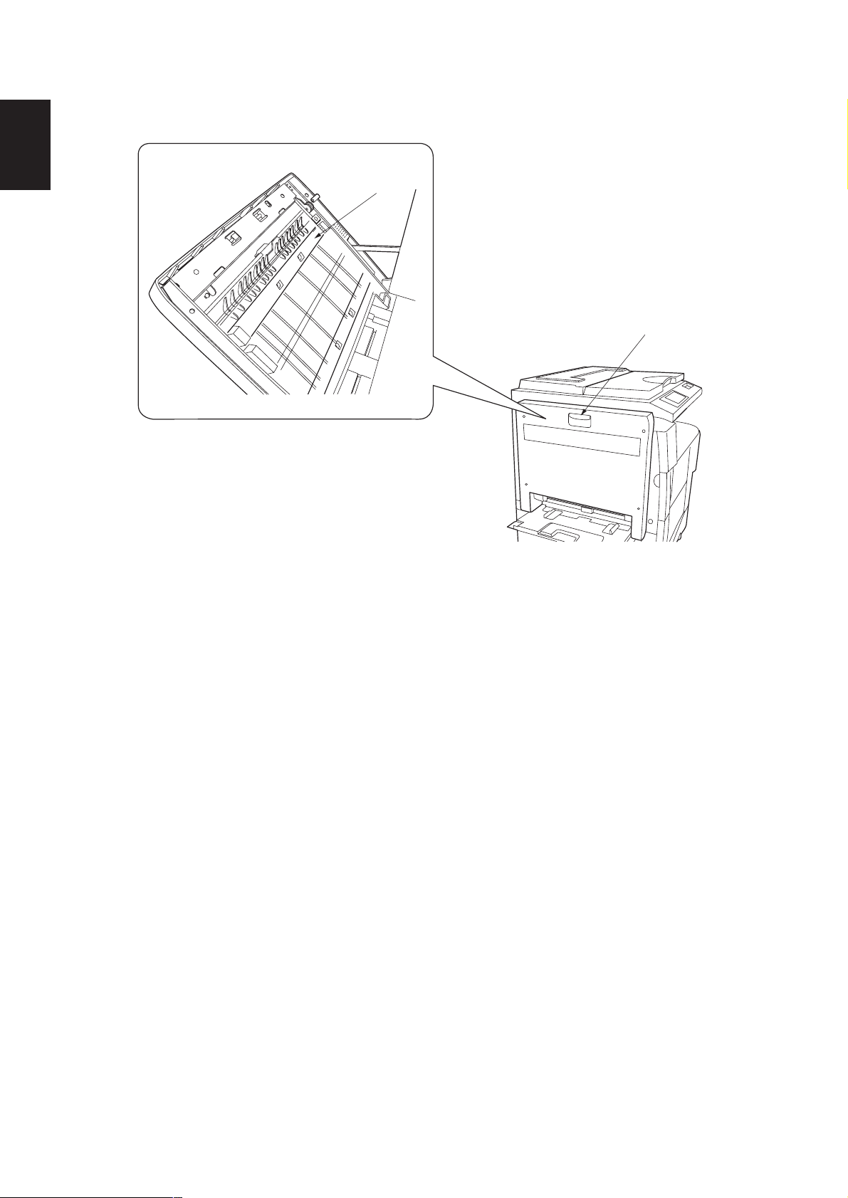
1-1-2 Part names and their functions
2
1
Figure 1-1-1
1 Duplex handle
2 Open/close guide
1-1-2
Page 5
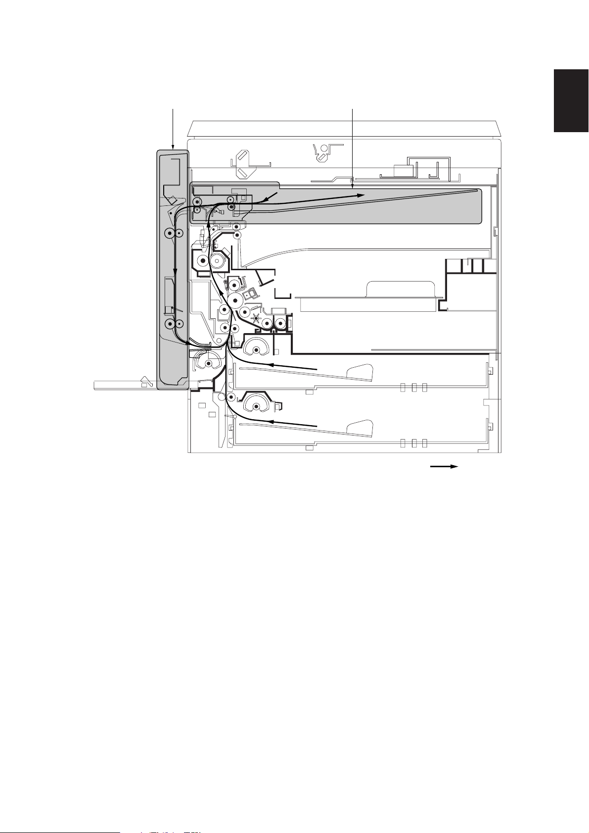
1-1-3 Machine cross section
3A6
2 1
1-1
Figure 1-1-2
1 Feedshift section
2 Duplex unit
Paper path
1-1-3
Page 6

3A6
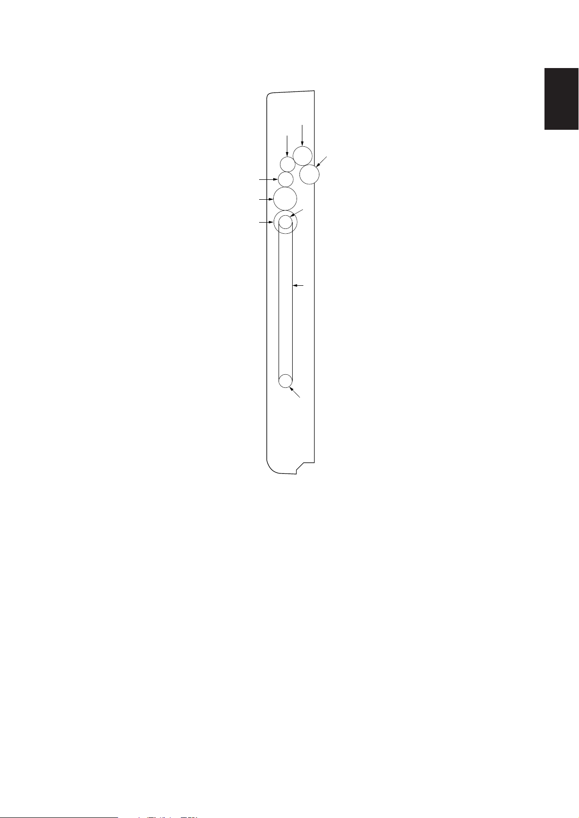
1-1-4 Drive system
1-1
(1) Feedshift section
7
1 Feedshift motor gear
2 Gear 19/38
3 Gear 23
4 Gear 19
6
5
Figure 1-1-3
3
2
4
5 Gear 30
6 Gear 19/21
7 Gear 25
1
1-1-4
Page 7
(2) Duplex unit
3A6
1-1
2
3
1
4
5
6
7
8
9
1 Gear 20
2 Gear 20
3 Gear 16
4 Gear 16
5 Gear 25
Figure 1-1-4
6 Gear 25
7 Pulley 20
8 Duplex belt
9 Pulley 20
1-1-5
Page 8
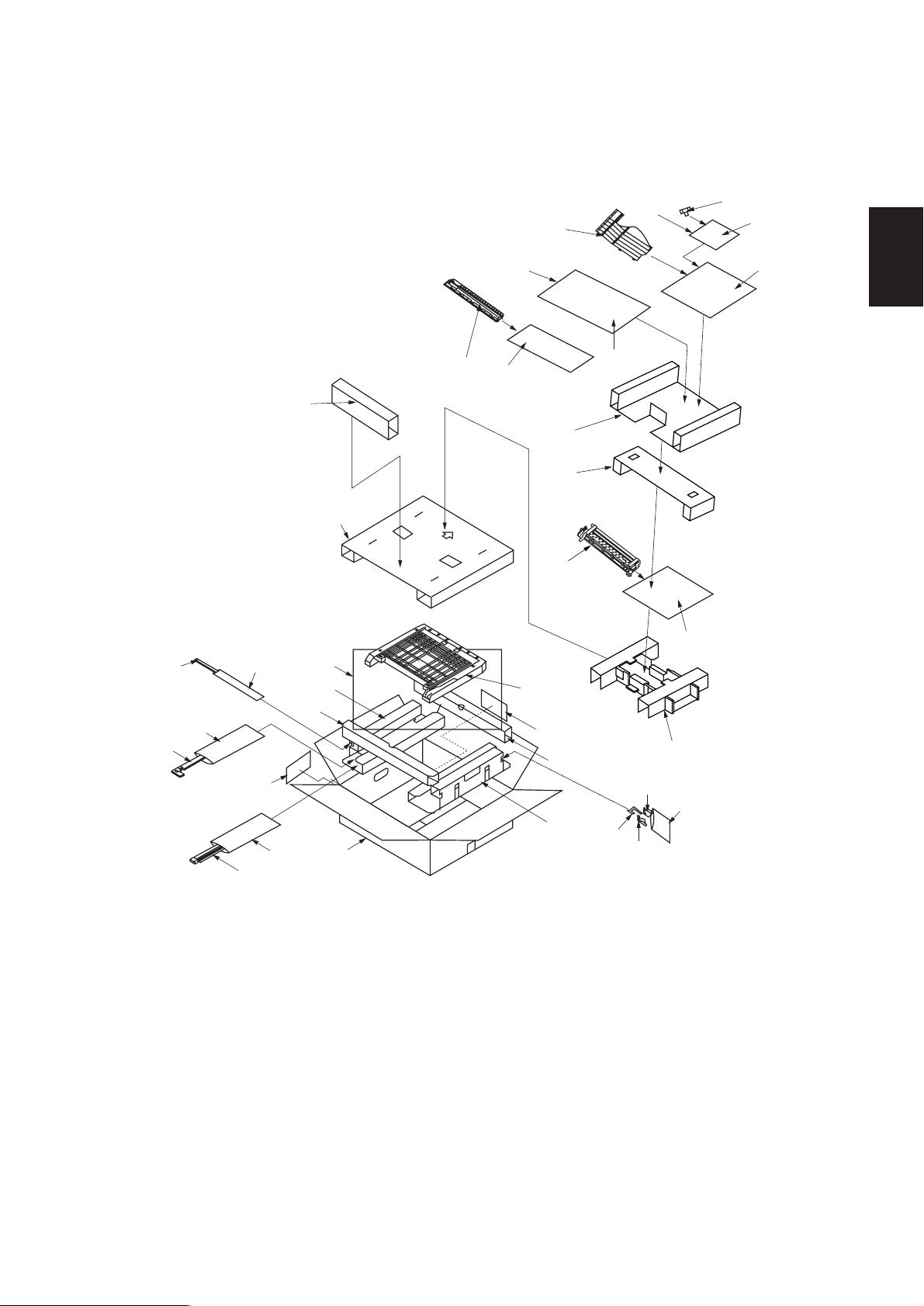
1-2-1 Unpacking
)⁄
¤
@
(
%^
0$
&*
#
„
ˇ
3A6
1-2
8
3
‰
9
¨
ˆ
‰
‚
‡
Á
fl
°
·
!
´
2
ˆ
‡
fl
‹
1
›
fi
7
4
∏
Œ
5
Ø
6
1 Feedshift unit
2 Duplex unit
3 Duplex joint
4 Front duplex fulcrum plate
5 Rear duplex fulcrum plate
6 Front fulcrum hook
7 Duplex stopper
8 Left cover
9 Entry guide
0 Two (2) stoppers 5
! Right eject cover
@ Job separator tray
# Pin
$ Two (2) cross-head bronze binding
screws BVM3 × 05
Figure 1-2-1 Unpacking
% Seven (7) cross head chrome binding
screws M3 × 14
^ One (1) cross-head chrome TP-A
screw M3 × 05
& One (1) cross-head tap-tight P chrome
TP-A screw M3 × 08
* One (1) cross-head tap-tight P chrome
TP-A screw M4 × 12
( Clamp
) Jam correction label
⁄ Eject section static eliminator
¤ Installation manual
‹ Upper pad
› Spacer
fi Plastic bag
fl Bottom pad
‡ Spacers
— Upper pad
· Outer case
‚ Spacer
ΠBottom pad
„ Plastic bag
´ Plastic bag
‰ Plastic bags
ˇ Plastic bag
Á Product cover
¨ Air-padded bag
ˆ Bar-code label
Ø Air-padded bag
” Plastic bag
1-2-1
Page 9

3A6
1-3-1 Paper misfeed detection
(1) Paper misfeed indication
When paper jams, the machine immediately stops operation and the occurrence of a paper jam is indicated on the copier
operation panel.
To remove the jammed paper, open the duplex unit.
To reset the paper misfeed detection, open and close the duplex unit to turn the duplex open/close switch off and on.
DUPPCSW2
DUPPCSW1
1-3
RSW
Figure 1-3-1 Paper misfeed detection
1-3-1
Page 10

3A6
(2) Paper misfeed detection conditions
• Jam in feedshift section (jam code 51)
Duplex paper conveying switch 1 (DUPPCSW1) does not turn on within 1640 ms of the start of reverse rotation of the
feedshift motor (FSM).
1-3
FSM
DUPPCSW1
Rev. rotation
1640 ms
Off
On
Off
On
Timing chart 1-3-1
• Jam in duplex paper conveying section 1 (jam code 60)
Duplex paper conveying switch 2 (DUPPCSW2) does not turn on within 3360 ms of duplex paper conveying switch 1
(DUPPCSW1) turning on.
DUPPCSW1
DUPPCSW2
3360 ms
Off
On
Off
On
Timing chart 1-3-2
• Jam in duplex paper conveying section 2 (jam code 61)
Duplex paper conveying switch 2 (DUPPCSW2) does not turn off within 3360 ms of duplex paper conveying switch 1
(DUPPCSW1) turning off.
DUPPCSW1
DUPPCSW2
3360 ms
Off
On
Off
On
Timing chart 1-3-3
The registration switch (RSW) of the copier does not turn on within 3300 ms of duplex paper conveying switch 2
(DUPPCSW2) turning on.
DUPPCSW2
RSW (copier)
3300 ms
Off
On
Off
On
Timing chart 1-3-4
1-3-2
Page 11

(3) Paper misfeeds
Problem Causes Check procedures/corrective measures
(1)
Paper jams in the
duplex unit when the
main switch is turned
on.
A piece of paper torn from
copy paper is caught
around duplex paper
conveying switch 1 or 2.
Defective duplex paper
conveying switch 1.
Remove any found.
With 5 V DC present at CN5-11 on the copier main PCB, check if
CN5-10 on the main PCB remains low when duplex paper
conveying switch 1 is turned on and off. If it does, replace duplex
paper conveying switch 1.
3A6
(2)
Paper jams in the
feedshift section
during copying (jam
in feedshift section).
(3)
Paper jams in the
duplex unit during
copying (jam in
duplex paper
conveying section 1).
(4)
Paper jams in the
duplex unit during
copying (jam in
duplex paper
conveying section 2).
Defective duplex paper
conveying switch 2.
Defective duplex paper
conveying switch 1.
Check if the right eject
pulley or right eject roller is
deformed.
Defective duplex paper
conveying switch 2.
Check if the duplex pulley
or upper duplex roller is
deformed.
Defective duplex paper
conveying switch 2.
Defective copier
registration switch.
Check if the duplex pulley
or lower duplex roller is
deformed.
With 5 V DC present at CN5-8 on the copier main PCB, check if
CN5-7 on the main PCB remains low when duplex paper
conveying switch 2 is turned on and off. If it does, replace duplex
paper conveying switch 2.
With 5 V DC present at CN5-11 on the copier main PCB, check if
CN5-10 on the main PCB remains high when duplex paper
conveying switch 1 is turned on and off. If it does, replace duplex
paper conveying switch 1.
Check visually and replace the pulley or roller if deformed.
With 5 V DC present at CN5-8 on the copier main PCB, check if
CN5-7 on the main PCB remains high when duplex paper
conveying switch 2 is turned on and off. If it does, replace duplex
paper conveying switch 2.
Check visually and replace the pulley or roller if deformed.
With 5 V DC present at CN5-8 on the copier main PCB, check if
CN5-7 on the main PCB remains low when duplex paper
conveying switch 2 is turned on and off. If it does, replace duplex
paper conveying switch 2.
With 5 V DC present at CN3-6 on the copier main PCB, check if
CN3-7 on the main PCB remains high when the registration
switch is turned on and off. If it does, replace the registration
switch.
Check visually and replace the pulley or roller if deformed.
1-3
1-3-3
Page 12

3A6
1-3-2 Electrical problems
Problem Causes Check procedures/corrective measures
(1)
The feedshift
solenoid does not
operate.
Broken feedshift solenoid
coil.
Poor contact of the
feedshift solenoid
connector terminals.
Check for continuity across the coil. If none, replace the feedshift
solenoid.
Reinsert the connector. Also check for continuity within the
connector cable. If none, remedy or replace the cable.
1-3
(2)
The feedshift motor
does not operate.
Defective main PCB.
Broken feedshift motor coil.
Poor contact of the
feedshift motor connector
terminals.
Defective copier main PCB.
Defective motor driver
PCB.
Run maintenance item U033 and check if CN16-4 and CN16-5
on the copier main PCB go low. If not, replace the main PCB.
Check for continuity across the coil. If none, replace the feedshift
motor.
Reinsert the connector. Also check for continuity within the
connector cable. If none, remedy or replace the cable.
Run maintenance item U030 and check if CN18-7 on the copier
main PCB goes low. If not, replace the main PCB.
Run maintenance item U030 and check if motor drive coil
energization signal is output at CN2-1, CN2-2, CN2-6 and CN2-5
on the motor driver PCB. If not, replace the motor driver PCB.
1-3-4
Page 13

1-3-3 Mechanical problems
Problem Causes/check procedures Corrective measures
(1)
Paper jams.
Check if the contact between the right eject
pulley and right eject roller is correct.
3A6
Check and remedy.
(2)
Abnormal noise is
heard.
Check if the contact between the left eject
pulley and left eject roller is correct.
Check if the duplex pulley, upper duplex roller
or lower duplex roller is deformed.
Check if rollers and gears operate smoothly.
Check and remedy.
Check visually and replace the pulley or
roller if deformed.
Apply grease to the bushings and gears.
1-3
1-3-5
Page 14

1-4-1 Precautions for assembly and disassembly
(1) Precautions
• Be sure to turn the main switch off and disconnect the power plug before starting disassembly.
• When handling PCBs, do not touch connectors with bare hands or damage the board.
• Do not touch any PCB containing ICs with bare hands or any object prone to static charge.
• Use the following testers when measuring voltages:
Hioki 3200
Sanwa MD-180C
Sanwa YX-360TR
Beckman TECH300
Beckman DM45
Beckman 330*
Beckman 3030*
Beckman DM850*
Fluke 8060A*
Arlec DMM1050
Arlec YF1030C
* Capable of measuring RMS values.
• Prepare the following as test originals:
1. NTC (new test chart)
2. NPTC (newspaper test chart)
3A6
1-4
1-4-1
Page 15

1-4
Printer leading edge margin
for duplex copying
(second face, 3 ± 2.5 mm)
3A6
1-4-2 Procedure for assembly and disassembly
(1) Adjusting the margin for printing
Perform the following adjustment if the printer leading edge margin for duplex copying (second face) is not correct.
Procedure
Start
Enter maintenance mode.
Enter “402” using the numeric
keys.
Press the start key.
Figure 1-4-1
Select “TRAIL 2” using the
cursor up/down keys.
Press the interrupt key.
Press the start key to
output a test pattern.
Is the margin correct?
Yes
Press the stop/clear key.
Exit maintenance mode.
End
Press the start key.
The new setting is stored.
No
Change the value using the
cursor left/right keys.
Setting range: –5.0 to +10.0
Reference: 4.5
Changing the value by 1 moves the margin by
0.5 mm.
Increasing the value makes the margin wider
and decreasing it makes the margin narrower.
1-4-2
Page 16

3A6
Original Copy
example 1
Copy
example 2
(2) Adjusting the amount of slack at the registration roller
Perform the following adjustment if the leading edge of the copy image is missing or varies randomly, or if the copy paper is
Z-folded during duplex copying.
Procedure
Start
Enter maintenance mode.
Enter “051” using the numeric
keys.
Figure 1-4-2
Press the start key.
Select “DUPLEX” using the
cursor up/down keys.
Press the interrupt key.
Make a test copy in duplex mode.
Press the start key.
The new setting is stored.
1-4
Is the leading
edge of the image missing
or varying randomly
(copy example 1)?
No
Is the copy paper
Z-folded (copy example 2)?
No
Press the stop/clear key.
Exit maintenance mode.
End
Yes
Yes
Increase the value using the
cursor right key.
Decrease the value using the
cursor left key.
Setting range: –50 to +50
Reference: 0
Changing the value by 1
changes the amount of slack
by 0.1 mm.
Initial setting: 0
The greater the value,
the larger the amount of slack;
the smaller the value,
the smaller the amount of slack
1-4-3
Page 17

3A6
(3) Adjusting the center line of image printing
Make the following adjustment if there is a regular error between the center lines of the copy image and original when
copying using the duplex unit.
Procedure
1-4
Start
Enter maintenance mode.
Enter “034” using
the numeric keys.
Press the start key.
Select “ADJ. LSU OUT TIMING”
using the cursor up/down keys
and press the start key.
Select “LSU DUP” using
the cursor up/down keys.
Press the interrupt key.
Press the start key to
output a test pattern.
Correct image Output
Press the start key.
The new setting is stored.
Center line of printing
example 1
Figure 1-4-3
Output
example 2
Is the image correct?
Yes
Press the stop/clear key
to exit maintenance mode.
End
For output example 1, decrease
the value using the cursor left key.
No
For output example 2, increase
the value using the cursor right
key.
Setting range: –5.0 to +5.0
Changing the value by 1 moves the
center line by 0.1 mm.
Initial setting: 0
1-4-4
Page 18

3A6
2-1-1 Feedshift section
The feedshift section consists of the components shown in Figure 2-1-1. It switches the path for the paper conveyed from
the copier during duplex copying.
47 56
3
1 Right eject pulley
2 Right eject roller
3 Left eject pulley
4 Left eject roller
5 Upper guide
9
Figure 2-1-1 Feedshift section
18
2
6 Lower right guide
7 Lower left guide
8 Job separator tray
9 Feedshift eject switch (FSESW)
0 Ejected paper detection switch (EPDSW)
0
2-1
EPDSW
CN2-1 –
CN2-6
CN6-13
FSESW
CN16-7
FSM
FSSOL
CN16-4, 5
MPCB (copier)
Figure 2-1-2 Feedshift section block diagram
MDPCB
CN1-1 –
CN1-10
CN18-1 –
CN18-10
2-1-1
Page 19

3A6
(1) Paper conveying operation in the feedshift section
In duplex mode, when the reverse face of the paper is copied, the feedshift solenoid (FSSOL) turns on and the feedshift
guide of the copier operates to switch the paper path to the feedshift section. When the trailing edge of the paper passes the
paper conveying switch (PCSW), the feedshift motor (FSM) reverses, rotating the right eject roller in the reverse direction to
switch back the paper into the duplex unit.
If the job separator tray is selected for the copy eject location, copied paper is conveyed through the feedshift section to the
job separator tray without being switched back.
2-1
PCSW: ON
Feedshift guide
(FSSOL: ON)
PCSW: OFF
Right eject roller
(FSM: Fwd. rotation)
Right eject roller
(FSM: Rev. rotation)
2-1-2
Figure 2-1-3
Page 20

3A6
2-1-2 Duplex unit
The duplex unit consists of the components shown in Figure 2-1-4. In duplex mode, after copying on to the reverse face of
the paper, the paper is reversed in the feedshift section and conveyed to the duplex unit. The paper is then conveyed to the
copier paper feed section by the upper and lower duplex rollers.
7
1
2
1 Duplex feedshift guide
2 Upper duplex roller
3 Lower duplex roller
4 Duplex pulley
5
4
8
3
6
4
Figure 2-1-4 Duplex unit
5 Open/close guide
6 Entry guide
7 Duplex paper conveying switch 1 (DUPPCSW1)
8 Duplex paper conveying switch 2 (DUPPCSW2)
DUPPCSW1
CN5-10
2-1
DUPPCSW2
CN5-7
MPCB
(copier)
Figure 2-1-5 Duplex unit block diagram
2-1-3
Page 21

2-2-1 Electrical parts layout
3A6
5
6
47
2
1
Machine front Machine inside
3
Machine rear
Figure 2-2-1 Feedshift unit
1. Motor driver PCB (MDPCB) ......................... Controls the feedshift motor.
2. Duplex open/close switch (DUPOCSW) ...... Detects if the duplex unit is opened/closed.
3. Feedshift eject switch (FSESW) .................. Detects a paper jam in the feedshift unit.
4. Ejected paper detection switch (EPDSW) ... Detects the presence of paper on the job separator tray.
5. Feedshift motor (FSM) ................................. Drives the feedshift section.
6. Feedshift solenoid (FSSOL) ........................ Operates the feedshift guide of the copier.
7. LED .............................................................. Indicates when the job separator tray is full.
2-2
2-2-1
Page 22

3A6
1
2
2-2
Machine front
Figure 2-2-2 Duplex unit
1. Duplex paper conveying switch 1
(DUPPCSW1) .............................................. Detects a paper jam in the duplex unit.
2. Duplex paper conveying switch 2
(DUPPCSW2) .............................................. Detects a paper jam in the duplex unit.
Machine inside
Machine rear
2-2-2
Page 23

Periodic maintenance procedures
3A6
Section
Paper Upper duplex roller Clean Every service Clean with alcohol or a dry cloth.
conveying
section
Maintenance
part/location
Lower duplex roller Clean Every service Clean with alcohol or a dry cloth.
Job separator tray Clean Every service Spray air onto the black pad.
Method Maintenance cycle Points and cautions Page
2-3
2-3-1
 Loading...