

Page 1

MITAC 3.5” SBC M/B PD11KS
Product Guide
Page 2
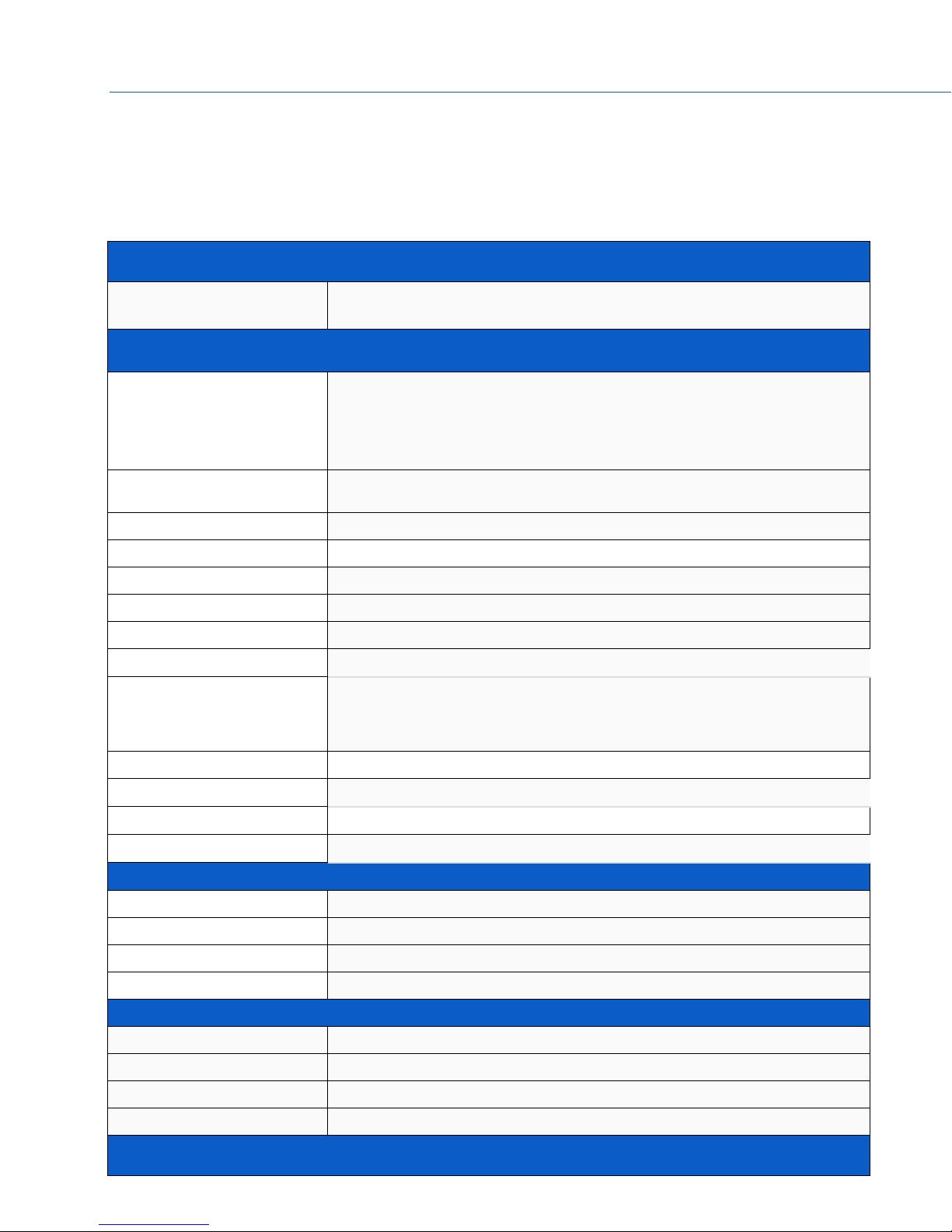
MECHANICAL
FORM FACTOR
3.5" SBC Embedded: 4” x 5.8” (102mm x 147mm)
SYSTEM
PROCESSOR
Intel® Kaby Lake-U i3-7100U (Dual Core, 3MB Cache, 2.40 GHz)
Option:
KBL celeron 3965U / i5-7300U / i7-7600U
SKL celeron 3955U / i3-6100U / i5-6300U / i7-6600U
CHIPSET
Intel® SoC integrated
MEMORY
DDR4 2133/2400, 260-pin SO-DIMM x 2, Max. 32 GB (Non-ECC)
GRAPHICS
Intel® HD Graphics
ETHERNET
Intel® I219LM Giga LAN + I211AT Giga LAN
AUDIO
Realtek ALC283
I/O CHIPSET
Nuvoton NCT6104D
TPM
Nuvoton NPCT650ABCYX TPM2.0
EXPANSION SLOT
Storage: PCI Express Full-Length Mini Card slot (USB / PCIe /
SATA)
Wireless: M.2 2230 E key (PCIe / USB)
BIOS
AMI BIOS
H/W MONITOR
Temperature Monitor, Voltage Monitor, Fan Monitor
WATCHDOG TIMER
1~255 Steps by Software Program
SMART FAN CONTROL
CPU Fan / System Fan
GRAPHICS
HDMI
Up to 4096 x 2160 @24 Hz
DISPLAYPORT
Up to 4096 x 2304 @60 Hz
LVDS
Up to 1920 x 1200 @60 Hz
eDP(Option)
Up to 4096 x 2304 @60 Hz
REAR I/O
USB
USB 3.0 x 4
DISPLAY I/O
HDMI x 1, DP x 1
AUDIO I/O
Audio combo jack (Mic-in and Line-out) x 1
LAN I/O
RJ-45 x 2
INTERNAL CONNECTORS
Desktop Board Features
This chapter briefly describes the features of
Table 1 summarizes the major features
Feature Summary
3.5” SBC M/B PD11KS.
of the M/B
2
Page 3
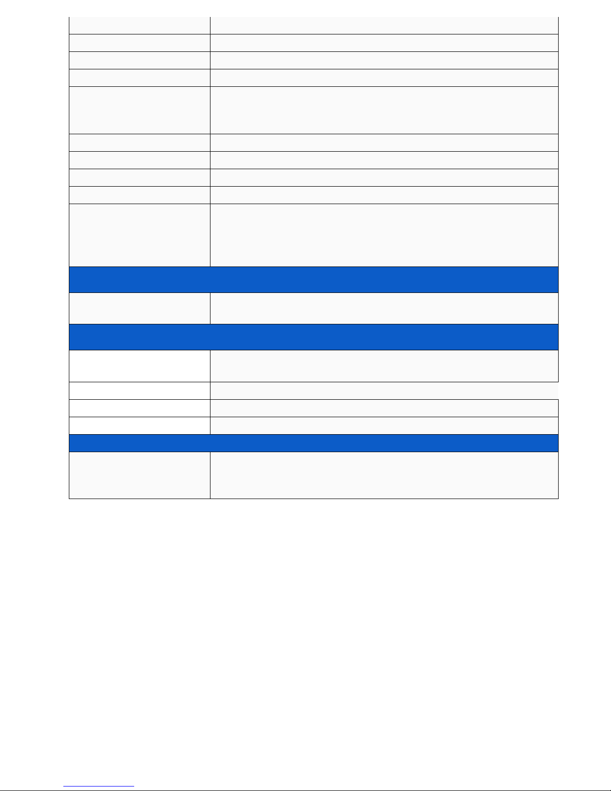
STORAGE
SATAIII x 1
USB
USB2.0 x 2
DISPLAY I/O
LVDS x 1,
Backlight Connector x 1
AUDIO I/O
Audio Header Supporting System Stereo Speaker or Buzzer x 1
Audio Header without Amplifier x 1 (for Extra Amplifier Board for
System Speaker)
SERIAL PORT
RS-232 x 4 (One Supports RS-232/422/485)
GPIO
MiAPI Header (Programmable. Support GPIO x 10) x 1
FAN
4PIN PWM Fan Header x 1
POWER
8~24V ATX Power Connector x 1, AT/ATX Mode Select Jumper x 1
OTHERS
MiAPI: Programmable header (support GPIO x10, SMBUSx1,
UARTx1, Watchdogx1) with API library supported for Windows OS
Chassis Front Panel Header (2x5PIN) x 1
CMOS Jumper x 1
POWER REQUIREMENT
POWER INPUT
Power header 4PIN
DC-in 8~24V
ENVIRONMENTAL
OPERATING
TEMPERATURE
0 ~ 60°C (32 ~ 140°F)
STORAGE TEMPERATURE
-20 ~ 80°C (-4 ~176°F)
OPERATING HUMIDITY
10% ~ 95% R/H, non-condensing
CERTIFICATION
CE & FCC
OS
OS SUPPORT
KBL: Windows 10 64bit, Linux (support by request)
SKL: Windows 7 32/64bit, Windows 8.1 64bit, Windows 10 64bit,
Linux (support by request)
T
AB LE
1. MITAC D
ES KTO P BOA RD
3
PD11KS F
EA TURES
Page 4

3.5” SBC M/B Components
Figure 1 shows the approximate location of the major components on the top
MITAC 3.5” SBC
M/B PD11KS.
side of
FIGURE 1. MITAC 3.5” SBC M/B COMPONENTS
4
Page 5

TABLE 2. MITAC 3.5” SBC M/B COMPONENT LIST (SHOWN IN FIGURE 1)
5
Page 6

Processor
The board supports 6th generation Intel Core processors. Other processors may be
supported in the future. This board supports processors with a maximum wattage of
65 W Thermal Design Power (TDP).
NOTE
This board has specific requirements for providing power to the processor. Additional
power required will depend on configurations chosen by the integrator.
System Memory
NOTE
To be fully compliant with all applicable DDR SDRAM memory specifications, the board
should be populated with DIMMs that support the Serial Presence Detect (SPD) data
structure. This allows the BIOS to read the SPD data and program the chipset to
accurately configure memory settings for optimum performance. If non-SPD memory
is installed, the BIOS will attempt to correctly configure the memory settings, but
performance and reliability may be impacted or the DIMMs may not function under the
determined frequency.
The Desktop Board has t w o260-pin DDR4 SO-DIMM sockets with gold-plated contacts.
6
Page 7
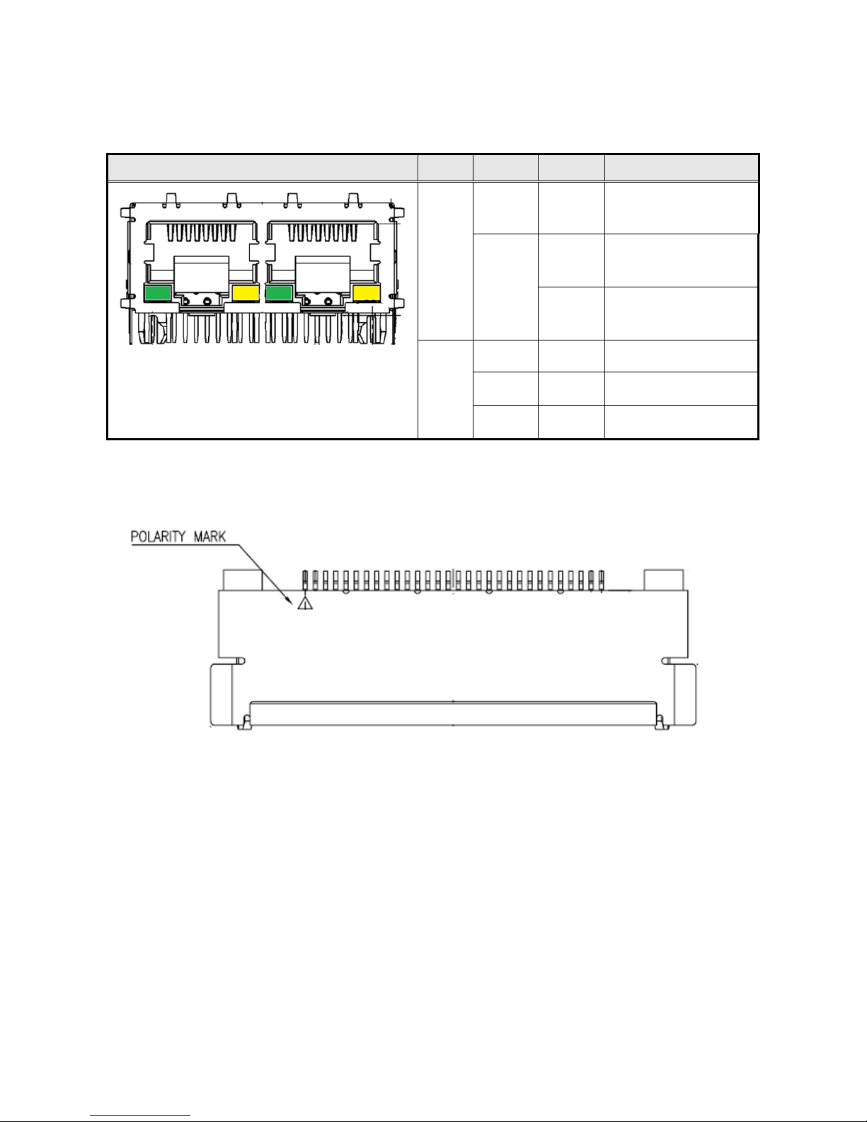
(Dual RJ45 Connector)
Diagram
LED
Color
State
Condition
Figure 1 LAN Connector (2D)▲
Link
N/A
Off
LAN link is not
established
Green
On
LAN link is
established
Blinking
LAN activity
occurring
Speed
N/A
Off
10 Mb/s data rate
Green
On
100 Mb/s data rate
Yellow
On
1000 Mb/s data rate
Table 3: RJ45 LED behavior ▲
(LVDS/eDP Connector)
Figure 2: LVDS/ eDP Connector (2D)▲
Page 8

Table 4: LVDS/ eDP Connector pin definition ▼
PIN
LVDS Define
eDP Define
1
LVDS0_LINK3_CON_DP
NC
2
LVDS0_LINK3_CON_DN
GND
3
LVDS0_LINK2_CON_DP
eDP_TX3_DN
4
LVDS0_LINK2_CON_DN
eDP_TX3_DP
5
LVDS0_LINK1_CON_DP
GND
6
LVDS0_LINK1_CON_DN
eDP_TX2_DN
7
LVDS0_LINK0_CON_DP
eDP_TX2_DP
8
LVDS0_LINK0_CON_DN
GND
9
LVDS1_LINK3_CON_DP
eDP_TX1_DN
10
LVDS1_LINK3_CON_DN
eDP_TX1_DP
11
LVDS1_LINK2_CON_DP
GND
12
LVDS1_LINK2_CON_DN
eDP_TX0_DN
13
LVDS1_LINK1_CON_DP
eDP_TX0_DP
14
LVDS1_LINK1_CON_DN
GND
15
LVDS1_LINK0_CON_DP
eDP_AUX_DN
16
LVDS1_LINK0_CON_DN
eDP_AUX_DP
17
GND
GND
18
Panel VDD
19
Panel VDD
20
Panel VDD
21
Panel VDD
22
Panel VDD
23
GND
24
GND
25
GND
26
LVDS0_CLK_CON_DP
GND
27
LVDS0_CLK_CON_DN
Hot Plug Detect
28
GND
29
GND
30
GND
31
DDC_SCL
GND
32
Backlight Enable
33
Backlight Control
Page 9
34
LVDS1_CLK_CON_DP
NC
35
LVDS1_CLK_CON_DN
NC
36
Backlight VCC
37
Backlight VCC
38
Backlight VCC
39
Backlight VCC
40
DDC_SDA
NC
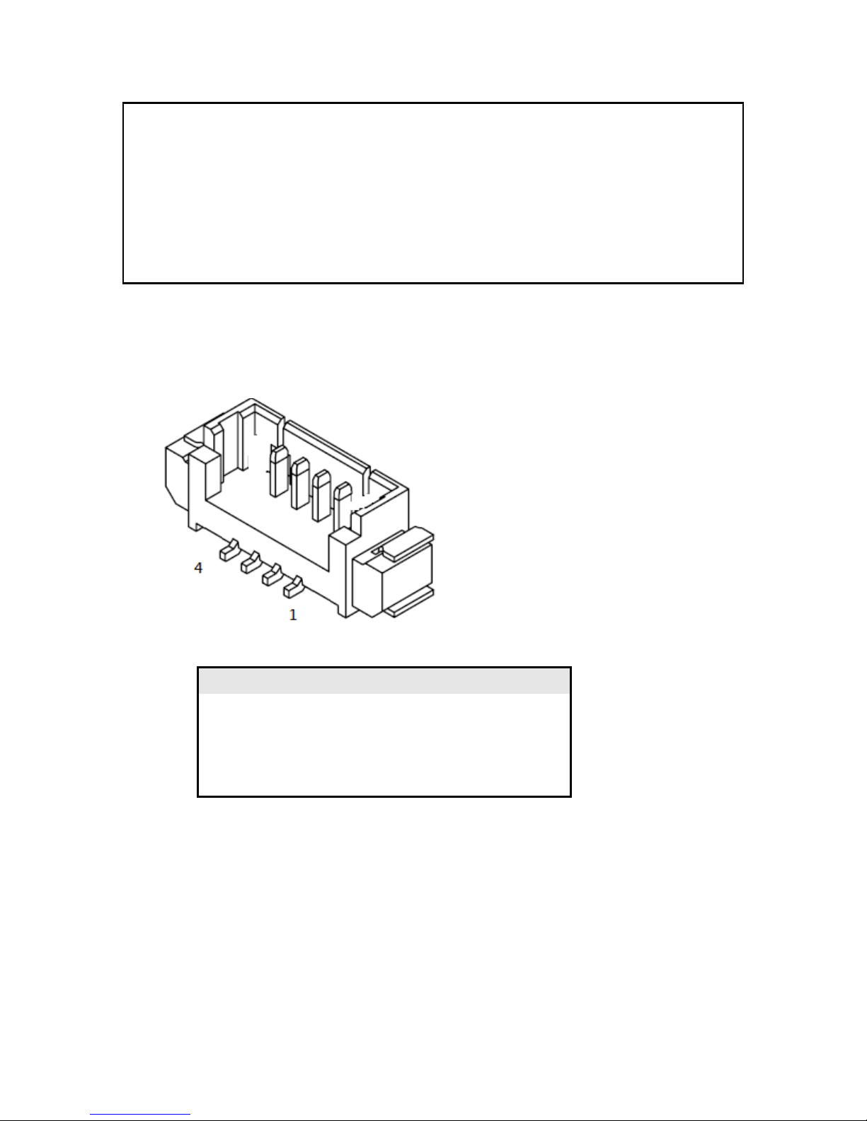
(External Speaker Socket)
Figure 3: External Speaker Socket (2D) ▼
Table 5: External Speaker Socket pin definition ▼
Pin
Signal Name
Description
1
VDD
+12V
2
LINE OUT L
[Out] Lift channel
3
LINE OUT R
[Out] Right channel
4
GND
Ground
Page 10
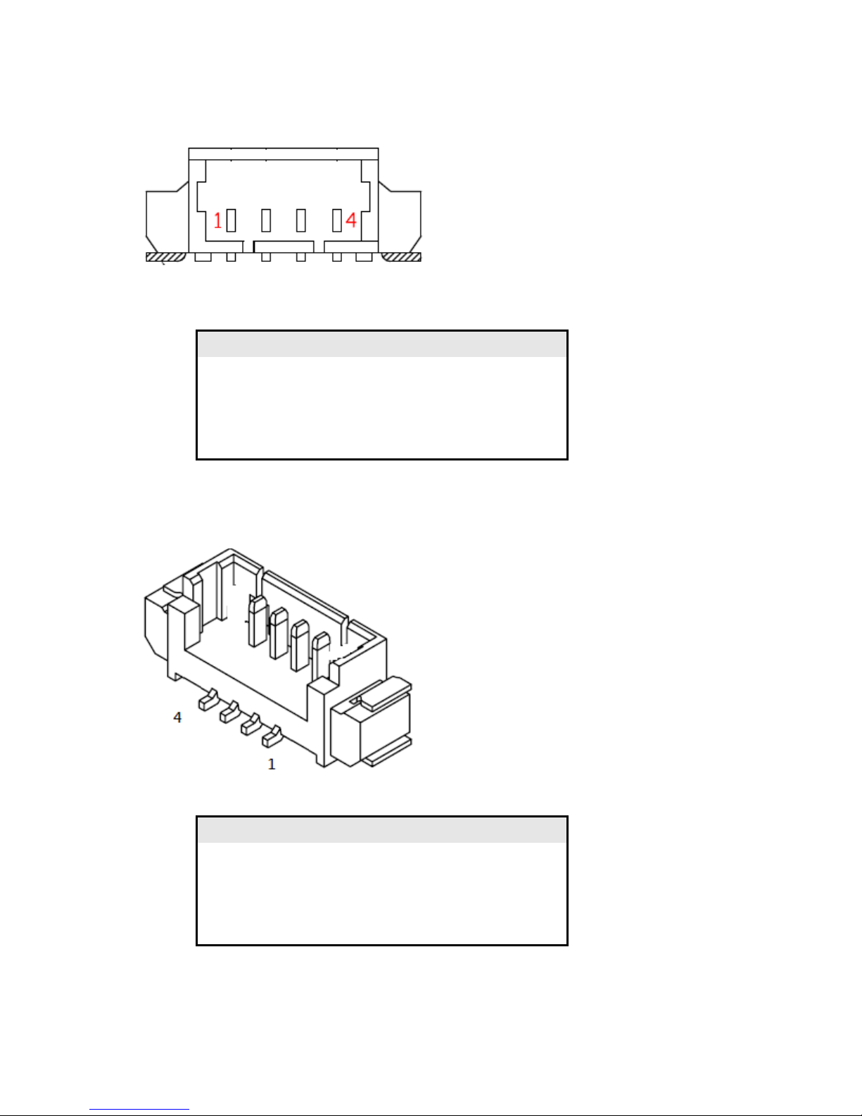
(Internal Speaker Socket)
Figure 4: Internal Speaker Socket (2D)▲
Table 6: Internal Speaker Socket pin definition ▼
Pin
Signal Name
Description
1
LINE OUT L-
[Out] Lift channel-
2
LINE OUT L+
[Out] Lift channel+
3
LINE OUT R-
[Out] Right channel-
4
LINE OUT R+
[Out] Right channel +
(SATA Power Socket)
Figure 5: SATA Power Socket (2D) ▼
Table 7: SATA Power Socket pin definition ▼
Pin
Signal Name
Description
1
VCC3
[Out] +3V
2
GND
[Out] Ground
3
VCC
[Out] +5V
4
12V
[Out] +12V
Page 11
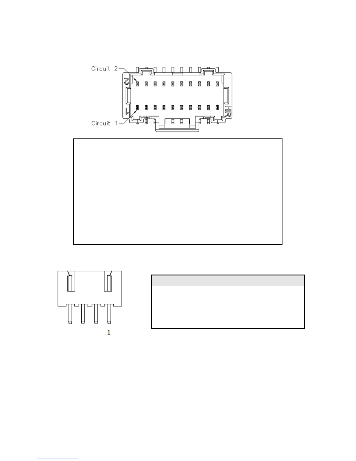
(MiAPI Socket)
Figure 6: MiAPI Socket (2D)▼
Table 8: MiAPI Socket pin definition ▲
(DC IN Power Socket)
Table 9: External Speaker Socket pin definition ▲
1
MAPI_GPIO1
2
VCC
3
MAPI_GPIO2
4
MAPI_GPIO6
5
MAPI_GPIO3
6
MAPI_GPIO7
7
MAPI_GPIO4
8
MAPI_GPIO8
9
MAPI_GPIO5
10
MAPI_GPIO9
11
WD_Time
12
MAPI_GPIO10
13
Power Button
14
SMBUS_DATA
15
UART_TX
16
SMBUS_CLK
17
UART_RX
18
5VSB
19
GND
20
NA
Pin
Signal Name
Description
1
VDD
[IN] 8~24V
2
VDD
[IN] 8~24V
3
GND
Ground
4
GND
Ground
Page 12
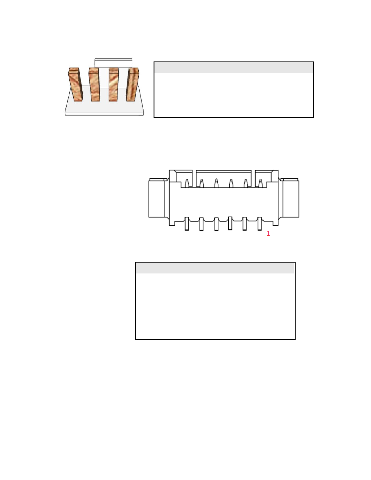
(FAN Socket)
Table 10: External Speaker Socket pin definition )▲
(Panel Backlight Control Cable Socket)
Figure 7: Backlight control cable Socket (2D)▲
Pin
Signal Name
Description
1
BKTL_EN
[Out] Lift channel-
2
BKLT_CTRL
[Out] Lift channel+
3
BKLT_PWR
[Out] Right channel-
4
BKLT_PWR
[Out] Right channel +
5
GND
Ground
6
GND
Ground
Table 11: Backlight control cable Socket pin definition ▲
Pin
Signal Name
Description
1
GND
Ground
2
VDD
[Out] 12V
3
CPU_FAN_TACH
FAN speed detect
4
CPU_FAN_CTRL
FAN speed control
Page 13
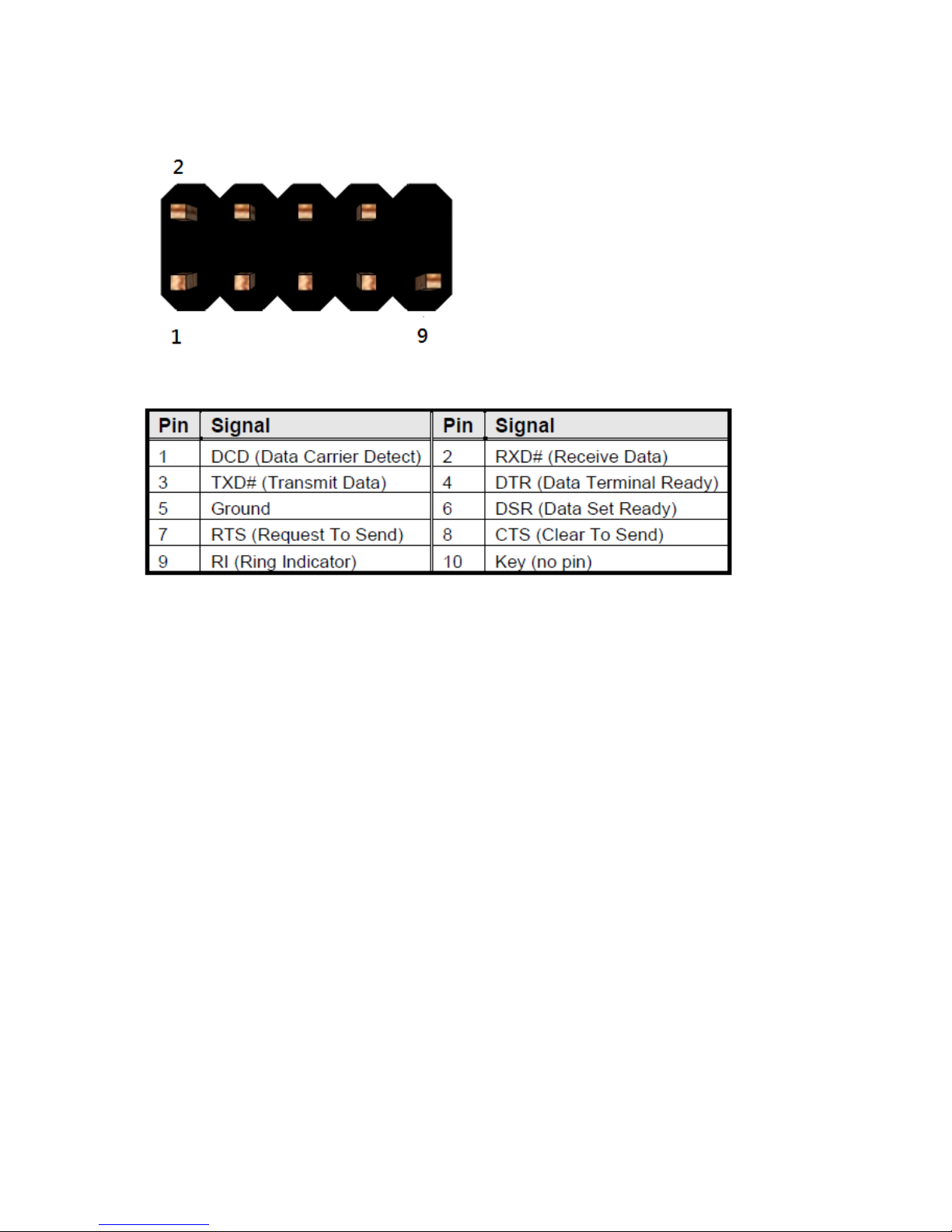
(COM Port Header)
Figure 8: RS232 COM Port Header (2D)▲
Table 12: RS232 COM Port pin definition ▲
Note. H4 COM port support RS422 & RS485 by BIOS setting.
Page 14
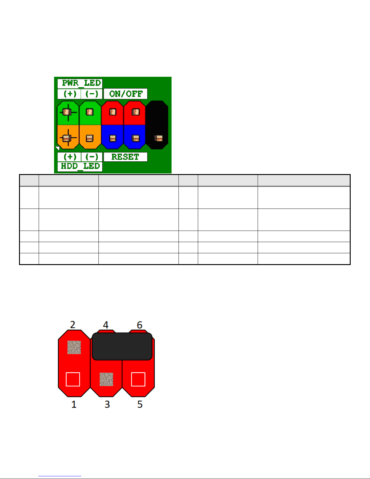
(Front Panel Header)
Pin
Signal Name
Description
Pin
Signal Name
Description
1
HDD_POWER_LED
Pull-up resistor (510Ω) to
+5V
2
POWER_LED_MAIN
[Out] Front panel LED (main
color)
3
HDD_LED#
[Out] Hard disk activity
LED
4
POWER_LED_ALT
[Out] Front panel LED (alt
color)
5
GROUND
Ground
6
POWER_SWITCH#
[In] Power switch
7
RESET_SWITCH#
[In] Reset switch
8
GROUND
Ground
9
VCC(+5V)
Power
10
KEY
No pin
Table 13 Front panel main header signals ▲
(Panel Power Selection Header)
Pins 6&4: Jumper position for +5V mode(Default)
Figure 9: Panel Power Selection Headers ▲
Page 15
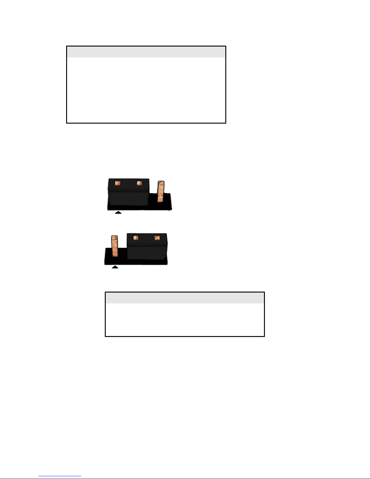
Table 14: Panel Power selection header pin definition ▲
(Panel Backlight Power Selection Header)
Pins 1&2: jumper position for +12V mode
Pins 2&3: jumper position for +5V mode
Table 15: Panel Power selection header pin definition ▲
Pin
Signal Name
Description
1
NC
No Pin
2
VCC3
+3V
3
12V
+12V
4
PANEL_PWR
[Out] output panel power
5
NC
No Pin
6
VCC
+5V
Pin
Signal Name
Description
1
12V
+12V
2
BKLT_PWR
Backlight Power
3
VCC
+5V
Page 16
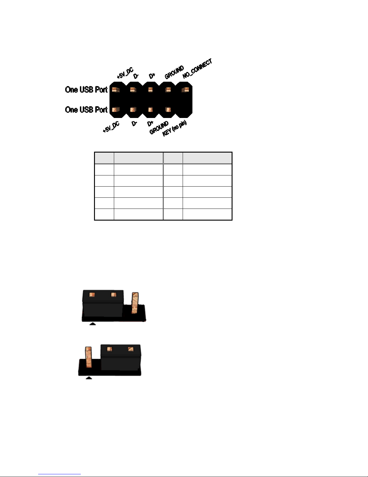
(Dual USB2.0 Header)
Figure 10: Dual USB2.0 header pin-out
Pin
Signal
Pin
Signal
1
+5V DC
2
+5V DC
3
Data (negative)
4
Data (negative)
5
Data (positive)
6
Data (positive)
7
Ground
8
Ground
9
Key (no pin)
10
No Connect
Table 16: Dual USB2.0 header pin definition ▲
( AT/ATX Mode Selection Header)
Pins 1&2: jumper position for AT mode
Pins 2&3: jumper position for ATX mode
Page 17
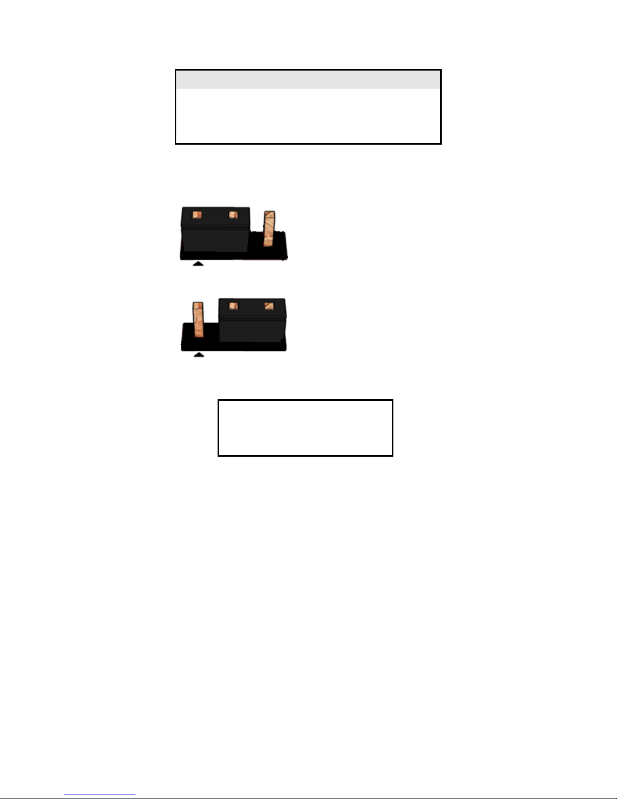
Table 17: Panel Power selection header pin definition ▲
( CMOS Clear Header)
Pins 1&2: Normal
Pins 2&3: jumper position for CMOS Reset
CMOS Clear
1-2
Clear CMOS
2-3
Normal
Table 18: CMOS Clear behavior ▲
Pin
Signal Name
Description
1
PSON_AT_N
Power on signal
2
SW_PWRBT_N
Power switch signal
3
NC
No connection
Page 18

MITAC 3.5” SBC M/B PD11KS
BIOS Specification
Page 19
MAIN PAGE
Main
Advanced
Chipset
Security
Boot
Save & Exit
BIOS Information
Item help
BIOS Vender
American Megatrends
Core Version
5.12
Compliancy
UEFI 2.6 ; PI 1.4
BIOS Version
D7760A01
Build Date
04/21/2017
ME FW Version
11.8.50.3399
Processor Information
Intel(R) CORE(TM) i5-7300U CPU @ 2.60GHz
Memory Information
Total Memory
32768 MB
Memory Frequency
2133 MHz
→←: Select Screen
↑↓: Select Item
SATA Devices
Enter: Select
SATA1
Empty
+/- : Change Opt.
MSATA
Empty
F1: General Help
F2: Previous Values
F3: Optimized Defaults
System Date
[Www mm/dd/yyyy]
F4: Save & Reset
System Time
[hh:mm:ss]
ESC: Exit
Version 2.18.1264. Copyright (C) 2017 American Megatrends, Inc.
Field Name
BIOS Vender
Default Value
AMI Megatrends
Comment
This field is not selectable. There is no help text associated with it.
Field Name
Core Version
Default Value
5.12
Comment
This field is not selectable. There is no help text associated with it.
Field Name
Compliancy
Default Value
UEFI 2.6 ; PI 1.4
Comment
This field is not selectable. There is no help text associated with it.
Field Name
BIOS Version
Default Value
Display the version of the BIOS
Page 20

Comment
This field is not selectable. There is no help text associated with it.
Field Name
Build Date
Default Value
Display build date of the BIOS
Comment
This field is not selectable. There is no help text associated with it.
Field Name
ME FW Version
Value
ME Firmware Version.
Comment
This field is not selectable. There is no help text associated with it.
Field Name
Processor Information
Value
Display the installed CPU brand.
Comment
This field is not selectable. There is no help text associated with it.
Field Name
Total Memory
Value
Display the installed memory size.
Comment
This field is not selectable. There is no help text associated with it.
Field Name
Memory Frequency
Value
Display the installed memory frequency.
Comment
This field is not selectable. There is no help text associated with it.
Field Name
SATA1
Value
Display the installed SATA port device.
Comment
This field is not selectable. There is no help text associated with it.
Field Name
MSATA
Value
Display the installed SATA port device.
Comment
This field is not selectable. There is no help text associated with it.
Field Name
System Date
Default Value
[Www mm/dd/yyyy]
Possible Value
Www : Mon/Tue/Wed/Thu/Fri/Sat/Sun
mm : 1-12
dd : 1-31
yyyy : 1998-9999
Help
Set the Date. Use Tab to switch between Date elements.
Field Name
System Time
Default Value
[hh :mm :ss]
Possible Value
hh : 0-23
mm : 0-59
ss : 0-59
Help
Set the Time. Use Tab to switch between Time elements.
Page 21
ADVANCED PAGE
Main
Advanced
Chipset
Security
Boot
Save & Exit
►CPU Configuration
Item help
►Trusted Computing
►ACPI Settings
►SMART Settings
►Super IO Configuration
►Hardware Monitor
→←: Select Screen
►S5 RTC Wake Settings
↑↓: Select Item
►Network Stack Configuration
Enter: Select
+/- : Change Opt
F1: General Help
F2: Previous Values
F3: Optimized Defaults
F4: Save & Reset
ESC: Exit
Version 2.18.1264. Copyright (C) 2017 American Megatrends, Inc.
Field Name
CPU Configuration
Help
CPU Configuration Parameters.
Comment
Press Enter when selected to go into the associated Sub-Menu.
Field Name
Trusted Computing
Help
Trusted Computing Settings
Comment
Press Enter when selected to go into the associated Sub-Menu.
Field Name
ACPI Settings
Help
System ACPI Parameters.
Comment
Press Enter when selected to go into the associated Sub-Menu.
Field Name
SMART Settings
Help
System SMART Settings.
Comment
Press Enter when selected to go into the associated Sub-Menu.
Field Name
Super IO Configuration
Help
System Super IO Chip Parameters.
Comment
Press Enter when selected to go into the associated Sub-Menu.
Field Name
Hardware Monitor
Page 22

Help
Monitor hardware status
Comment
Press Enter when selected to go into the associated Sub-Menu.
Field Name
S5 RTC Wake Settings
Help
Enable system to wake from S5 using RTC alarm.
Comment
Press Enter when selected to go into the associated Sub-Menu.
Field Name
Network Stack Configuration
Help
Network Stack Settings.
Comment
Press Enter when selected to go into the associated Sub-Menu.
Page 23
CPU CONFIGURATION
Main
Advanced
Chipset
Security
Boot
Save & Exit
CPU Configuration
Item help
Type
Intel(R) Core(TM) CPU
i5-7300U @ 2.60 GHz
ID
0x806E9
Speed
2700 MHz
L1 Data Cache
32 KB x 2
L1 Code Cache
32 KB x 2
L2 Cache
256 KB x 2
L3 Cache
3MB
L4 Cache
N/A VMX
Supported
SMX/TXT
Supported
→←: Select Screen
Hardware Prefetcher
[Enabled]
↑↓: Select Item
Adjacent Cache Line Prefetch
[Enabled]
Enter: Select
Active Processor Cores
[All]
+/- : Change Opt
Hyper-Threading
[Enabled]
F1: General Help
Intel Trusted Execution Technology
[Disabled]
F2: Previous Values
F3: Optimized Defaults
F4: Save & Reset
ESC: Exit
Version 2.18.1264. Copyright (C) 2017 American Megatrends, Inc.
Field Name
Type
Default Value
[Intel CPU Brand String]
Comment
This field is not selectable. There is no help text associated with it.
Field Name
ID
Default Value
Displays CPU Signature
Comment
This field is not selectable. There is no help text associated with it.
Field Name
Speed
Default Value
Displays the CPU Speed
Comment
This field is not selectable. There is no help text associated with it.
Page 24

Field Name
L1 Data Cache
Default Value
L1 Data Cache Size
Comment
This field is not selectable. There is no help text associated with it.
Field Name
L1 Code Cache
Default Value
L1 Code Cache Size
Comment
This field is not selectable. There is no help text associated with it.
Field Name
L2 Cache
Default Value
L2 Cache Size
Comment
This field is not selectable. There is no help text associated with it.
Field Name
L3 Cache
Default Value
L3 Cache Size
Comment
This field is not selectable. There is no help text associated with it.
Field Name
L4 Cache
Default Value
L4 Cache Size
Comment
This field is not selectable. There is no help text associated with it.
Field Name
VMX
Default Value
VMX Supported or Not
Comment
This field is not selectable. There is no help text associated with it.
Field Name
SMX/TXT
Default Value
SMX/TXT Supported or Not
Comment
This field is not selectable. There is no help text associated with it.
Field Name
Hardware Prefetcher
Default Value
[Enabled]
Possible Value
Enabled
Disabled
Help
To turn on/off the MLC streamer prefetcher.
Field Name
Adjacent Cache Line Prefetch
Default Value
[Enabled]
Possible Value
Enabled
Disabled
Help
To turn on/off the prefetching of adjacent cache lines.
Field Name
Active Processor Cores
Default Value
[All]
Possible Value
All
1
Help
Number of cores to enable in each processor package.
Field Name
Hyper-Threading
Default Value
[Enabled]
Page 25

Possible Value
Enabled
Disabled
Help
Enabled for Windows XP and Linux (OS optimized for Hyper-Threading
Technology) and Disabled for other OS (OS not optimized for HyperThreading Technology).
Field Name
Intel Trusted Execution Technology
Default Value
[Disabled]
Possible Value
Enabled
Disabled
Help
Enables utilization of additional hardware capabilities provided by Intel
(R) Trusted Execution Technology.
Changes require a full power cycle to take effect.
Page 26
TRUSTED COMPUTING (OPTIONAL)
Main
Advanced
Chipset
Security
Boot
Save &
Exit
TPM20 Device Found
Item help
Vender : NTC
Firmware Version: 1.3
Security Device Support
[Enable]
Pending operation
[None]
→←: Select Screen
TPM2.0 UEFI Spec Version
[TCG_2]
↑↓: Select Item
Enter: Select
+/- : Change Opt
F1: General Help
F2: Previous Values
F3: Optimized Defaults
F4: Save & Reset
ESC: Exit
Version 2.18.1264. Copyright (C) 2017 American Megatrends, Inc.
ESC: Exit
Field Name
Security Device SUPPORT
Default Value
[Enable]
Possible Value
Enable
Disable
Help
Enables or Disables BIOS support for security device. O.S. will not
show Security Device. TCG EFI protocol and INT1A interface will not
be available.
Field Name
Pending operation
Default Value
[None]
Possible Value
None
TPM Clear
Help
Schedule an Operation for the Security Device. NOTE: Your Computer
will reboot during restart in order to change State of Security Device.
Field Name
TPM2.0 UEFI Spec Version
Default Value
[TCG_2]
Possible Value
TCG_1_2
TCG_2
Help
Select the TCG2 Spec Version Support,TCG_1_2: the Compatible mode
for Win8/Win10,TCG_2: Support new TCG2 protocol and event format
for Win10 or later.
Page 27

Page 28
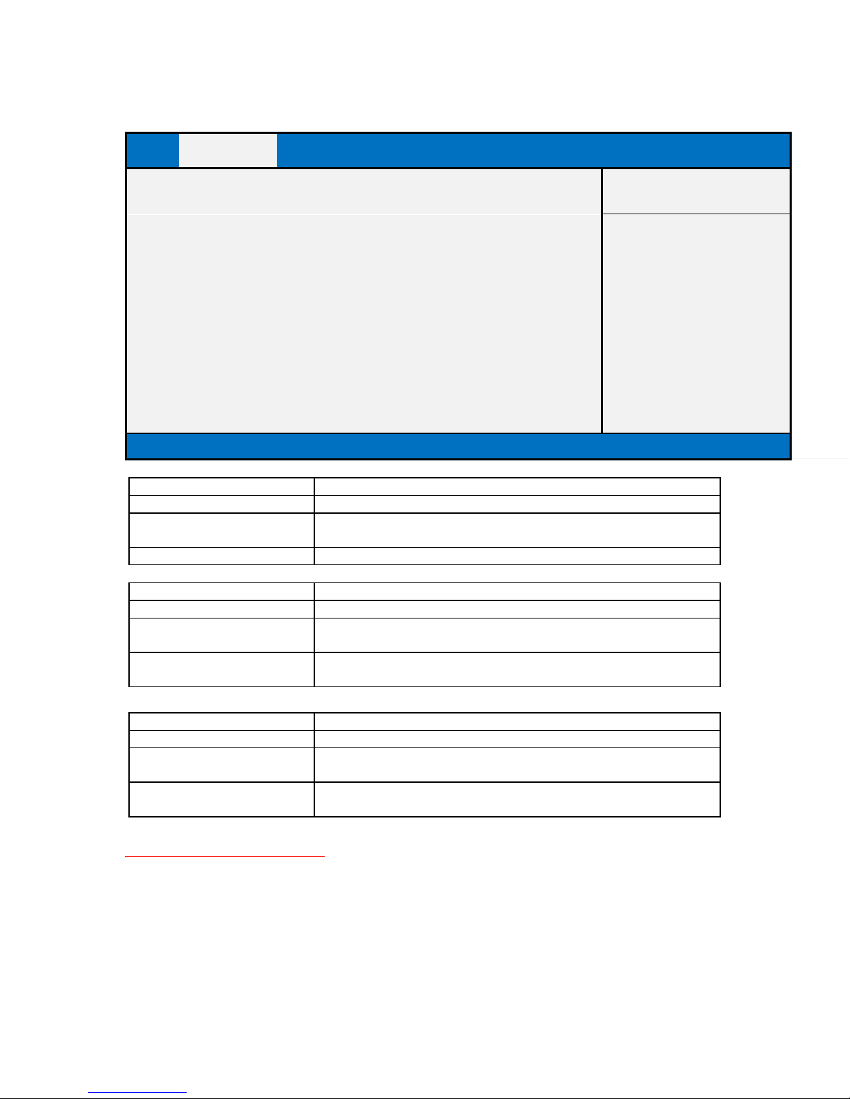
ACPI SETTINGS
Main
Advanced
Chipset
Security
Boot
Save &
Exit
ACPI Settings
Item help
Enable ACPI Auto Configuration
[Disabled]
→←: Select Screen
↑↓: Select Item
Enable Hibernation
[Enabled]
Enter: Select
ACPI Sleep State
[S3 (Suspend to RAM)]
+/- : Change Opt
F1: General Help
F2: Previous Values
F3: Optimized Defaults
F4: Save & Reset
ESC: Exit
Version 2.18.1264. Copyright (C) 2017 American Megatrends, Inc.
ESC: Exit
Field Name
Enable ACPI Auto Configuration
Default Value
[Disabled]
Possible Value
Enabled
Disabled
Help
Enables or Disables BIOS ACPI Auto Configuration.
Field Name
Enable Hibernation
Default Value
[Enabled]
Possible Value
Enabled
Disabled
Help
Enables or Disables System ability to Hibernate (OS/S4 Sleep State).
This option may be not effective with some OS.
Field Name
ACPI Sleep State
Default Value
[S3 (Suspend to RAM)]
Possible Value
Suspend Disabled
S3 (Suspend to RAM)
Help
Select the highest ACPI sleep state the system will enter when the
SUSPEND button is pressed.
Page 29
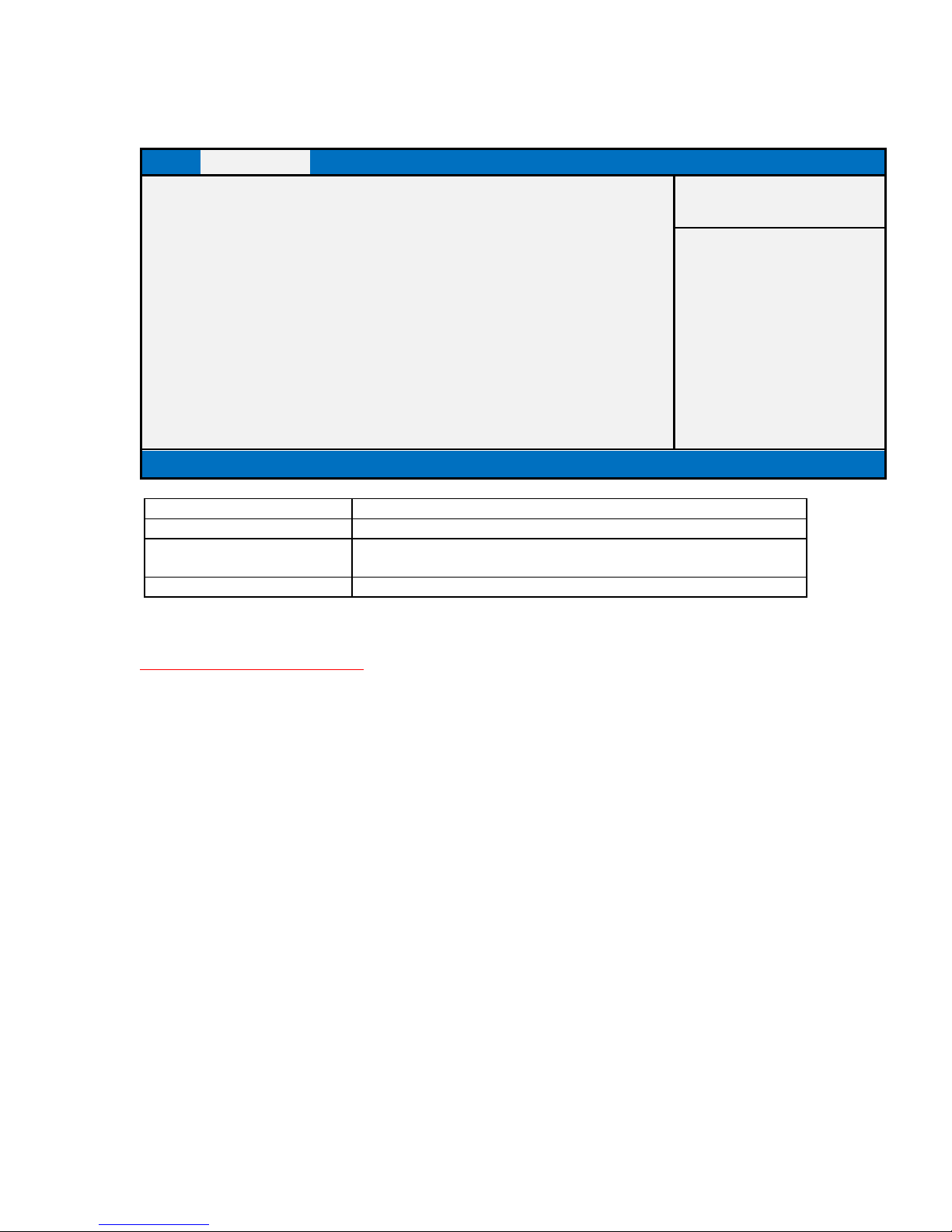
SMART SETTINGS
Main
Advanced
Chipset
Security
Boot
Save & Exit
SMART Settings
Item help
SMART Self Test
[Disabled]
→←: Select Screen
↑↓: Select Item
Enter: Select
+/- : Change Opt
F1: General Help
F2: Previous Values
F3: Optimized Defaults
F4: Save & Reset
ESC: Exit
Version 2.18.1264. Copyright (C) 2017 American Megatrends, Inc.
Field Name
SMART Self Test
Default Value
[Disabled]
Possible Value
Disabled
Enabled
Help
Run SMART Self Test on all HDDs during POST.
Page 30
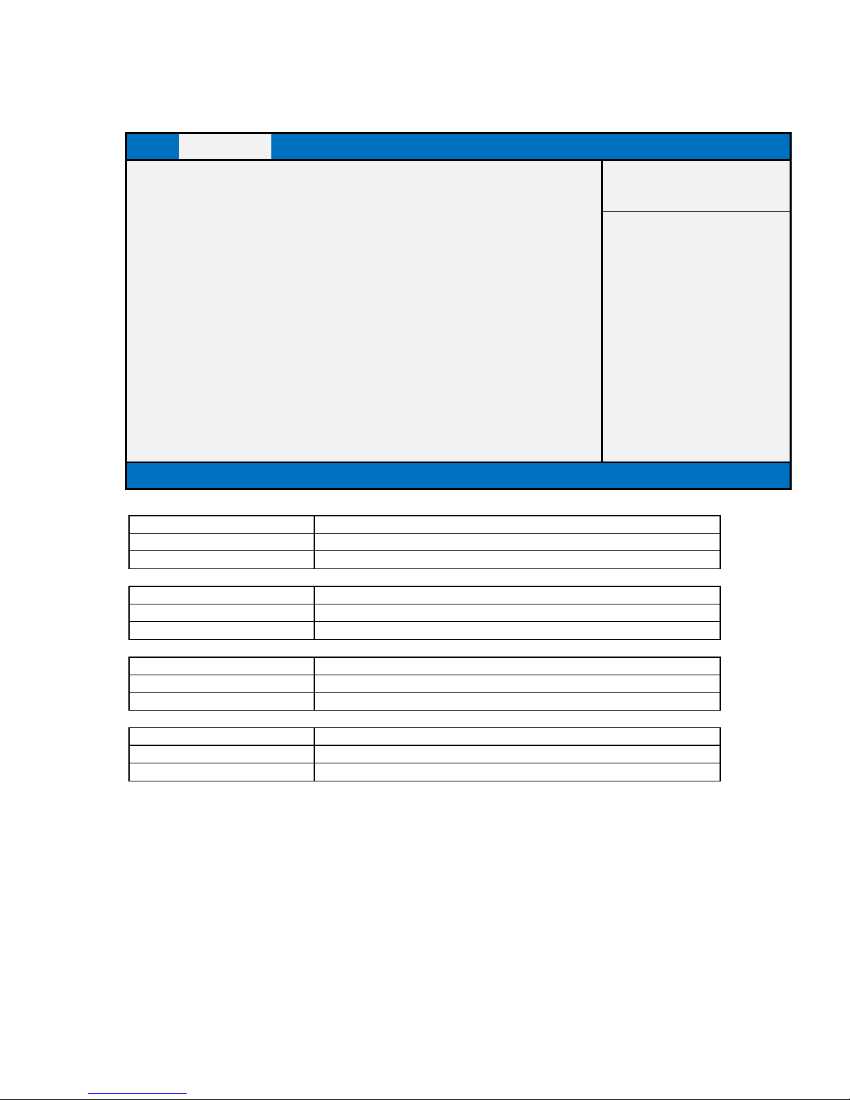
SUPER IO CONFIGURATION
Main
Advanced
Chipset
Security
Boot
Save & Exit
SIO Configuration
Item help
►Serial Port 1 Configuration
→←: Select Screen
►Serial Port 2 Configuration
↑↓: Select Item
►Serial Port 3 Configuration
Enter: Select
►Serial Port 4 Configuration
+/- : Change Opt
F1: General Help
F2: Previous Values
F3: Optimized Defaults
F4: Save & Reset
ESC: Exit
Version 2.18.1264. Copyright (C) 2017 American Megatrends, Inc.
Field Name
Serial Port 1 Configuration
Help
Set Parameters of Port 1 (COMA)
Comment
Press Enter when selected to go into the associated Sub-Menu.
Field Name
Serial Port 2 Configuration
Help
Set Parameters of Port 2 (COMB)
Comment
Press Enter when selected to go into the associated Sub-Menu.
Field Name
Serial Port 3 Configuration
Help
Set Parameters of Port 3 (COMC)
Comment
Press Enter when selected to go into the associated Sub-Menu.
Field Name
Serial Port 4 Configuration
Help
Set Parameters of Port 4 (COMD)
Comment
Press Enter when selected to go into the associated Sub-Menu.
Page 31
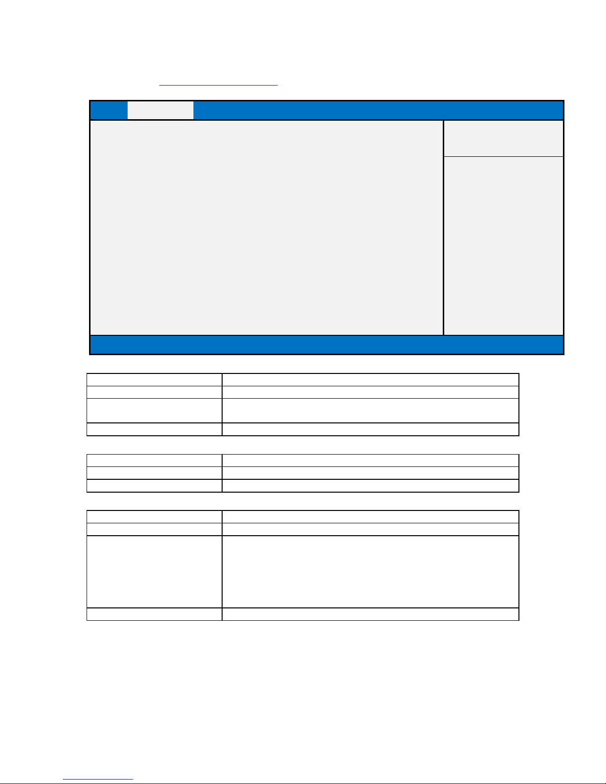
Serial Port 1 Configuration
Main
Advanced
Chipset
Security
Boot
Save & Exit
Serial Port 1 Configuration
Item help
Serial Port
[Enabled]
→←: Select Screen
Device Settings
IO=3E8h; IRQ=7;
↑↓: Select Item
Enter: Select
Change Settings
[Auto]
+/- : Change Opt
F1: General Help
F2: Previous Values
F3: Optimized Defaults
F4: Save & Reset
ESC: Exit
Version 2.18.1264. Copyright (C) 2017 American Megatrends, Inc.
Field Name
Serial Port
Default Value
[Enabled]
Possible Value
Disabled
Enabled
Help
Enable or Disable Serial Port(COM)
Field Name
Device Settings
Default Value
Device Super IO COM1 Address and IRQ.
Comment
This field is not selectable. There is no help text associated with it.
Field Name
Change Settings
Default Value
[Auto]
Possible Value
Auto
IO=3E8h; IRQ=7;
IO=3E8h; IRQ=3,4,5,6,7,9,10,11,12;
IO=2E8h; IRQ=3,4,5,6,7,9,10,11,12;
IO=2F0h; IRQ=3,4,5,6,7,9,10,11,12;
IO=2E0h; IRQ=3,4,5,6,7,9,10,11,12;
Help
Select an optimal settings for Super IO Device
Page 32
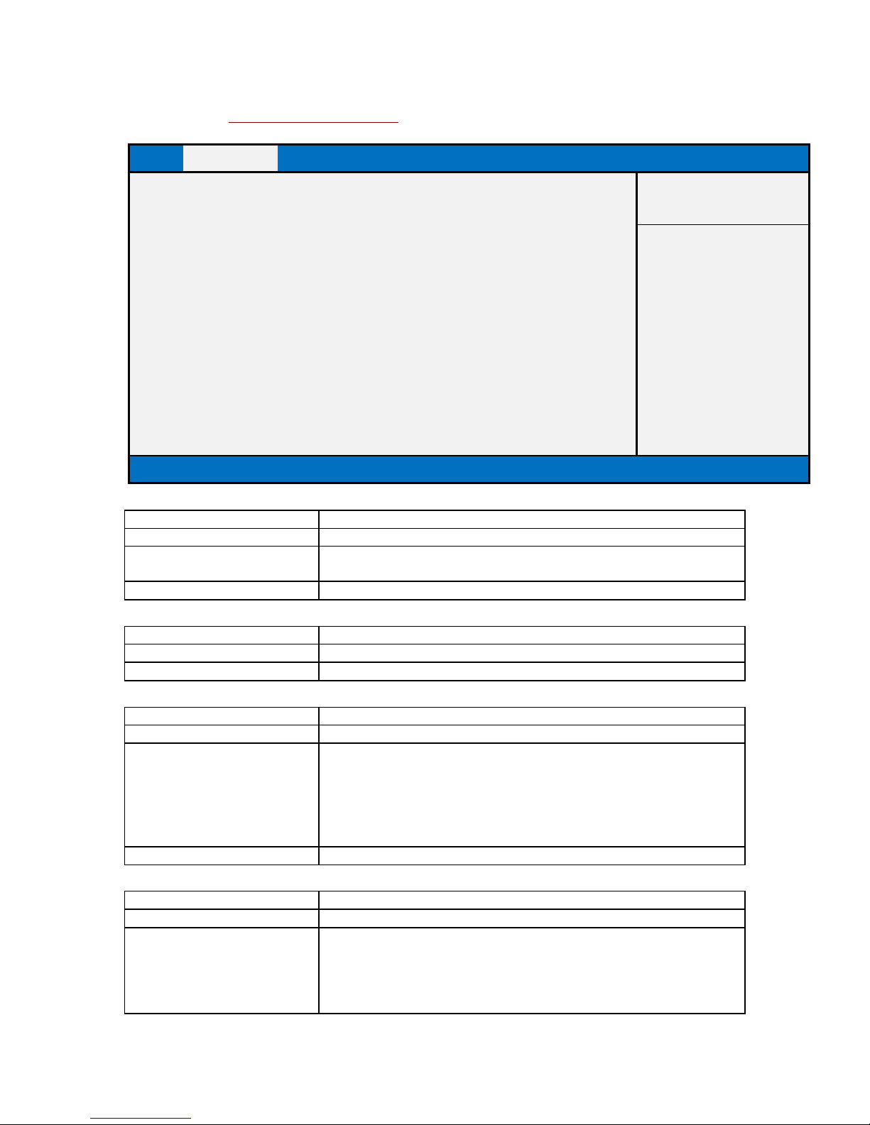
Serial Port 2 Configuration
Main
Advanced
Chipset
Security
Boot
Save & Exit
Serial Port 2 Configuration
Item help
Serial Port
[Enabled]
→←: Select Screen
Device Settings
IO=2E8h; IRQ=5;
↑↓: Select Item
Enter: Select
Change Settings
[Auto]
+/- : Change Opt
Mode Configuration
[3T/5R RS232]
F1: General Help
F2: Previous Values
F3: Optimized Defaults
F4: Save & Reset
ESC: Exit
Version 2.18.1264. Copyright (C) 2017 American Megatrends, Inc.
Field Name
Serial Port
Default Value
[Enabled]
Possible Value
Disabled
Enabled
Help
Enable or Disable Serial Port(COM)
Field Name
Device Settings
Default Value
Device Super IO COM2 Address and IRQ.
Comment
This field is not selectable. There is no help text associated with it.
Field Name
Change Settings
Default Value
[Auto]
Possible Value
Auto
IO=2E8h; IRQ=7;
IO=3E8h; IRQ=3,4,5,6,7,9,10,11,12;
IO=2E8h; IRQ=3,4,5,6,7,9,10,11,12;
IO=2F0h; IRQ=3,4,5,6,7,9,10,11,12;
IO=2E0h; IRQ=3,4,5,6,7,9,10,11,12;
Help
Select an optimal settings for Super IO Device
Field Name
Mode Configuration
Default Value
[3T/5R RS232]
Possible Value
1T/1R RS422
3T/5R RS232
1T/1R RS485 TX ENABLE Low Active
1T/1R RS422 with termination resistor
1T/1R RS485 with termination resistor TX ENABLE Low Active
Page 33

Disabled
Help
Configure serial port as RS232/RS422/RS485.
Page 34
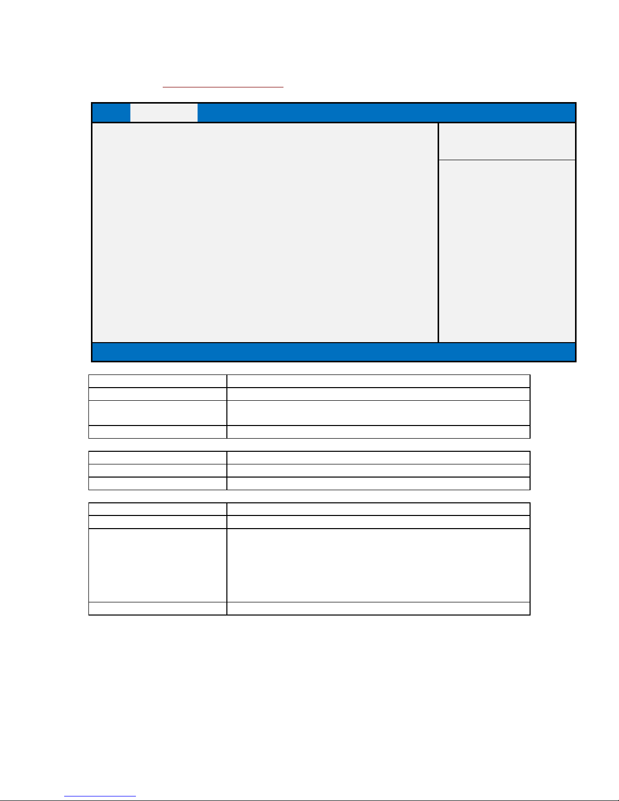
Serial Port 3 Configuration
Main
Advanced
Chipset
Security
Boot
Save & Exit
Serial Port 3 Configuration
Item help
Serial Port
[Enabled]
→←: Select Screen
Device Settings
IO=3F8h; IRQ=4;
↑↓: Select Item
Enter: Select
Change Settings
[Auto]
+/- : Change Opt
F1: General Help
F2: Previous Values
F3: Optimized Defaults
F4: Save & Reset
ESC: Exit
Version 2.18.1264. Copyright (C) 2017 American Megatrends, Inc.
Field Name
Serial Port
Default Value
[Enabled]
Possible Value
Disabled
Enabled
Help
Enable or Disable Serial Port(COM)
Field Name
Device Settings
Default Value
Device Super IO COM3 Address and IRQ.
Comment
This field is not selectable. There is no help text associated with it.
Field Name
Change Settings
Default Value
[Auto]
Possible Value
Auto
IO=3F8h; IRQ=4;
IO=3F8h; IRQ=3,4,5,6,7,9,10,11,12;
IO=2F8h; IRQ=3,4,5,6,7,9,10,11,12;
IO=3E8h; IRQ=3,4,5,6,7,9,10,11,12;
IO=2E8h; IRQ=3,4,5,6,7,9,10,11,12;
Help
Select an optimal settings for Super IO Device
Page 35
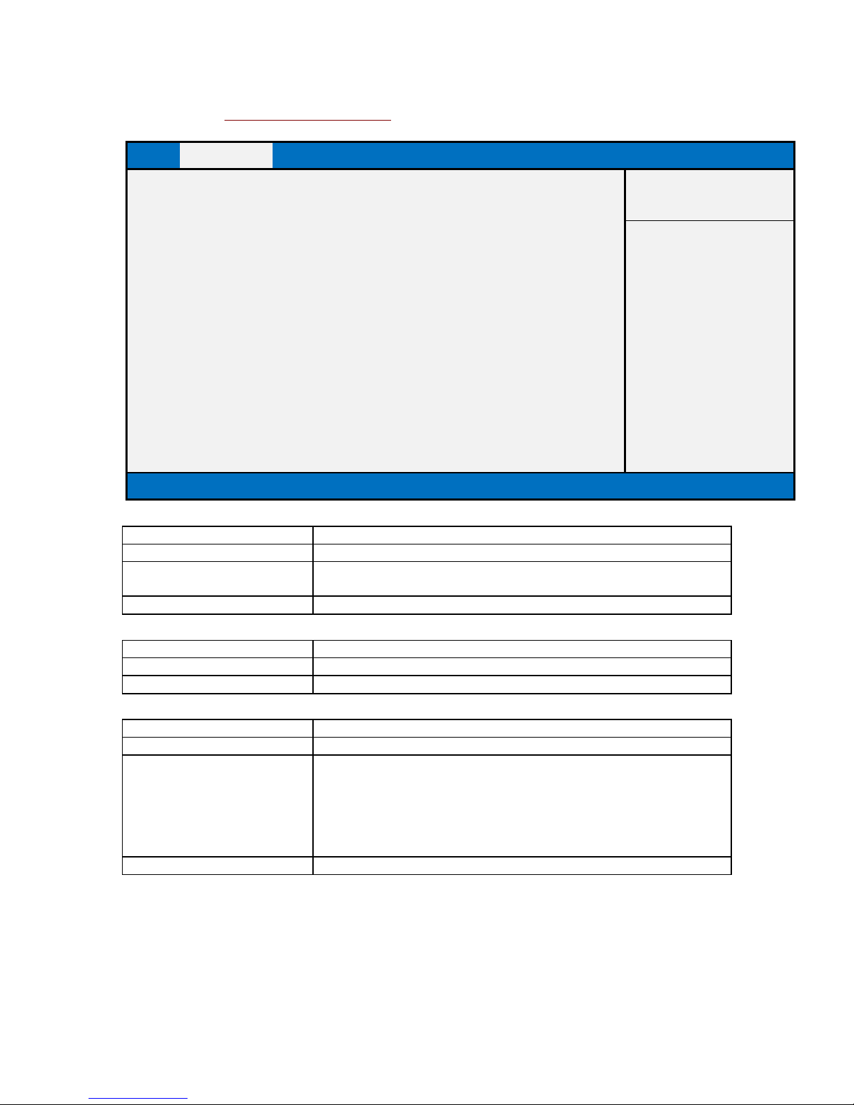
Serial Port 4 Configuration
Main
Advanced
Chipset
Security
Boot
Save & Exit
Serial Port 4 Configuration
Item help
Serial Port
[Enabled]
→←: Select Screen
Device Settings
IO=2F8h; IRQ=3;
↑↓: Select Item
Enter: Select
Change Settings
[Auto]
+/- : Change Opt
F1: General Help
F2: Previous Values
F3: Optimized Defaults
F4: Save & Reset
ESC: Exit
Version 2.18.1264. Copyright (C) 2017 American Megatrends, Inc.
Field Name
Serial Port
Default Value
[Enabled]
Possible Value
Disabled
Enabled
Help
Enable or Disable Serial Port(COM)
Field Name
Device Settings
Default Value
Device Super IO COM4 Address and IRQ.
Comment
This field is not selectable. There is no help text associated with it.
Field Name
Change Settings
Default Value
[Auto]
Possible Value
Auto
IO=2F8h; IRQ=3;
IO=3F8h; IRQ=3,4,5,6,7,9,10,11,12;
IO=2F8h; IRQ=3,4,5,6,7,9,10,11,12;
IO=3E8h; IRQ=3,4,5,6,7,9,10,11,12;
IO=2E8h; IRQ=3,4,5,6,7,9,10,11,12;
Help
Select an optimal settings for Super IO Device
Page 36

HARDWARE MONITOR
Main
Advanced
Chipset
Security
Boot
Save & Exit
PC Health Status
Item help
CPU temperature
: xx °C
→←: Select Screen
CPU VR temperature
: xx °C
↑↓: Select Item
DIMM temperature
: xx °C
Enter: Select
Fan Speed
: xxxx RPM
+/- : Change Opt
1V StandBy
: x.xxx V
F1: General Help
CPU Vcore
: x.xxx V
F2: Previous Values
System Memory
: x.xxx V
F3: Optimized Defaults
+12V StandBy
: x.xxx V
F4: Save & Reset
ESC: Exit
Version 2.18.1264. Copyright (C) 2017 American Megatrends, Inc.
Page 37
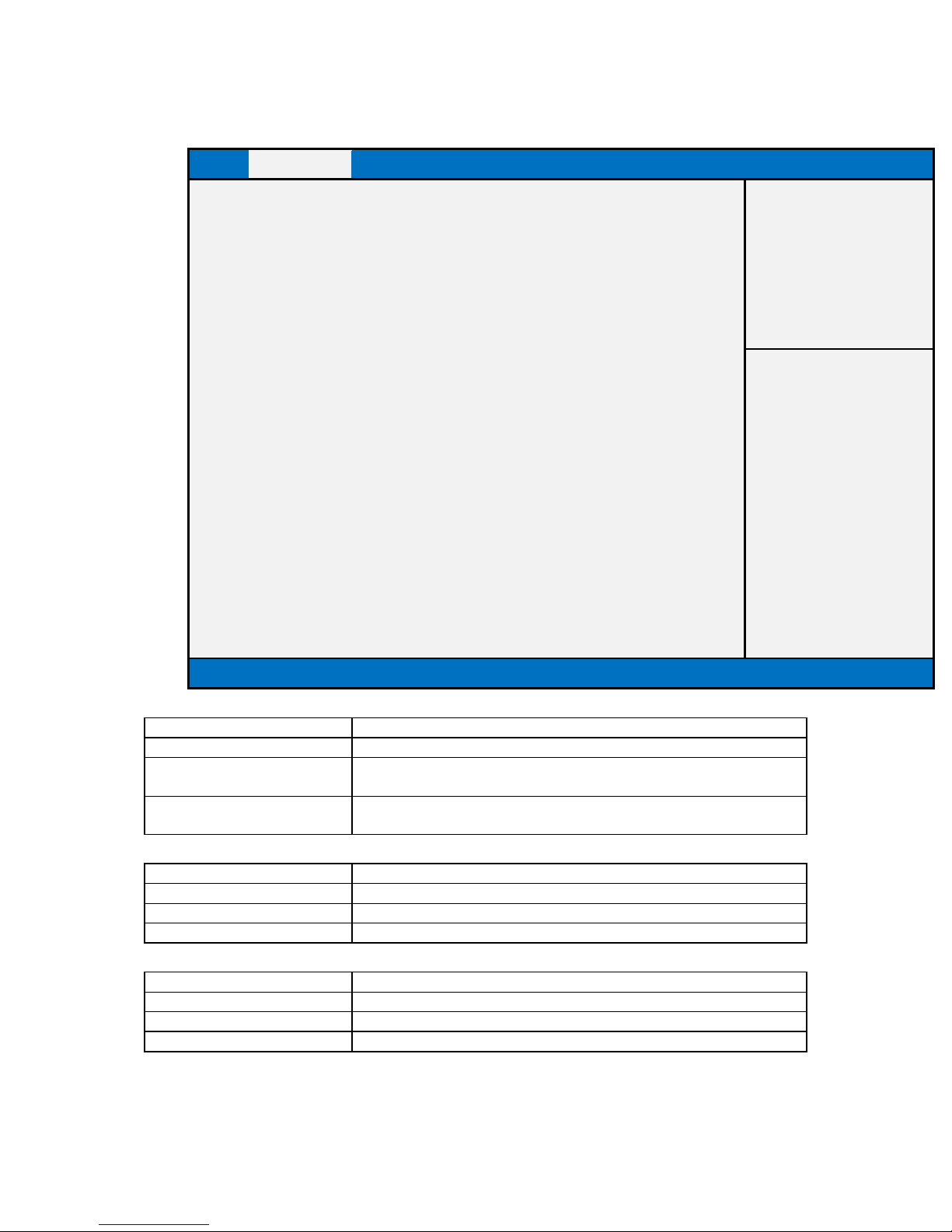
S5 RTC WAKE SETTINGS
Main
Advanced
Chipset
Security
Boot
Save & Exit
Wake system from S5
[Disabled]
Item help
Wake up hour
0 Wake up minute
0 Wake up second
0
→←: Select Screen
↑↓: Select Item
Enter: Select
+/- : Change Opt
F1: General Help
F2: Previous Values
F3: Optimized Defaults
F4: Save & Reset
ESC: Exit
Version 2.18.1264. Copyright (C) 2017 American Megatrends, Inc.
Field Name
Wake system from S5
Default Value
[Disabled]
Possible Value
Disabled
Fixed Time
Help
Enabler or disable System wake on alarm event, Select FixedTime,
system will wake on the hr::min::sec specified.
Field Name
Wake up hour(Show when Wake system from S5 set to Fixed Time)
Default Value
0
Possible Value
0-23
Help
Select 0-23 For example enter 3 for 3am and 15 for 3pm
Field Name
Wake up minute(Show when Wake system from S5 set to Fixed Time)
Default Value
0
Possible Value
0-59
Help
0 - 59
Page 38

Field Name
Wake up second(Show when Wake system from S5 set to Fixed Time)
Default Value
0
Possible Value
0 - 59
Help
0 - 59
Page 39
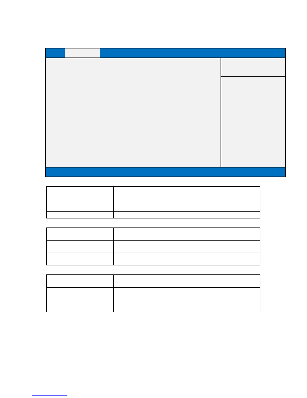
NETWORK STACK CONFIGURATION
Main
Advanced
Chipset
Security
Boot
Save & Exit
Item help
Network stack
[Disabled]
Ipv4 PXE Support
[Disabled]
→←: Select Screen
Ipv6 PXE Support
[Disabled]
↑↓: Select Item
Enter: Select
+/- : Change Opt
F1: General Help
F2: Previous Values
F3: Optimized Defaults
F4: Save & Reset
ESC: Exit
Version 2.18.1264. Copyright (C) 2017 American Megatrends, Inc.
Field Name
Network stack
Default Value
[Disabled]
Possible Value
Disabled (Restore non-Windows 8 Default)
Enabled
Help
Enable/Disable UEFI Network stack.
Field Name
Ipv4 PXE Support
Default Value
[Disabled]
Possible Value
Disabled
Enabled
Help
Enable Ipv4 PXE Boot Support. If disabled IPV4 PXE boot option will
not be created.
Field Name
Ipv6 PXE Support
Default Value
[Disabled]
Possible Value
Disabled
Enabled
Help
Enable Ipv6 PXE Boot Support. If disabled IPV6 PXE boot option will
not be created.
Page 40
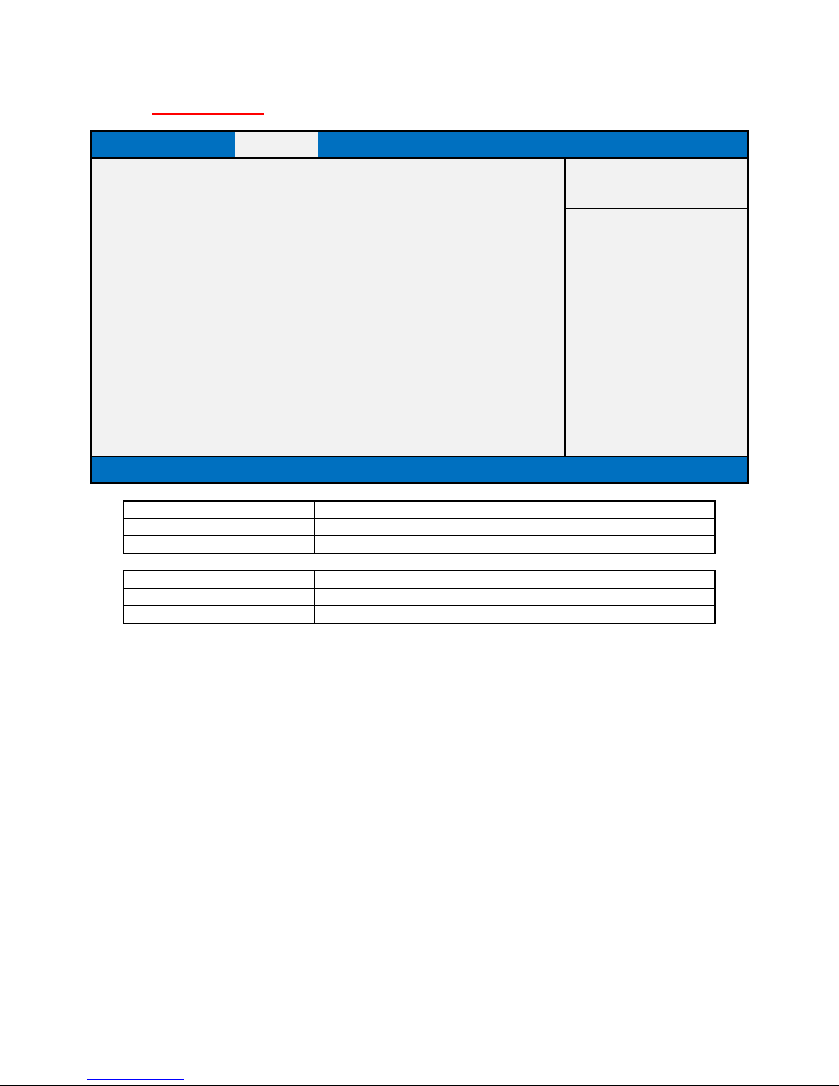
CHIPSET PAGE
Main
Advanced
Chipset
Security
Boot
Save & Exit
►System Agent (SA) Configuration
Item help
►PCH-IO Configuration
→←: Select Screen
↑↓: Select Item
Enter: Select
+/- : Change Opt
F1: General Help
F2: Previous Values
F3: Optimized Defaults
F4: Save & Reset
ESC: Exit
Version 2.18.1264. Copyright (C) 2017 American Megatrends, Inc.
Field Name
System Agent (SA) Configuration
Help
System Agent (SA) Parameters
Comment
Press Enter when selected to go into the associated Sub-Menu.
Field Name
PCH-IO Configuration
Help
PCH Parameters
Comment
Press Enter when selected to go into the associated Sub-Menu.
Page 41
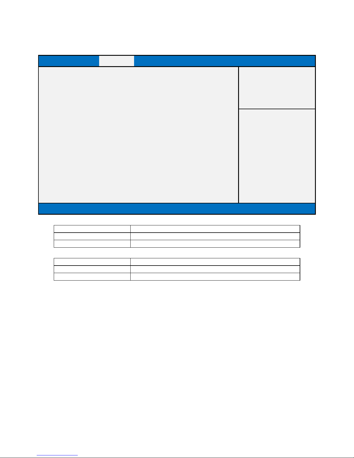
SYSTEM AGENT (SA) CONFIGURATION
Main
Advanced
Chipset
Security
Boot
Save & Exit
System Agent (SA) Configuration
Item help
►Memory Configuration
►Graphics Configuration
→←: Select Screen
↑↓: Select Item
Enter: Select
+/- : Change Opt
F1: General Help
F2: Previous Values
F3: Optimized Defaults
F4: Save & Reset
ESC: Exit
Version 2.18.1264. Copyright (C) 2017 American Megatrends, Inc.
Field Name
Memory Configuration
Help
Memory Configuration Parameters
Comment
Press Enter when selected to go into the associated Sub-Menu.
Field Name
Graphics Configuration
Help
Graphics Configuration
Comment
Press Enter when selected to go into the associated Sub-Menu.
Page 42
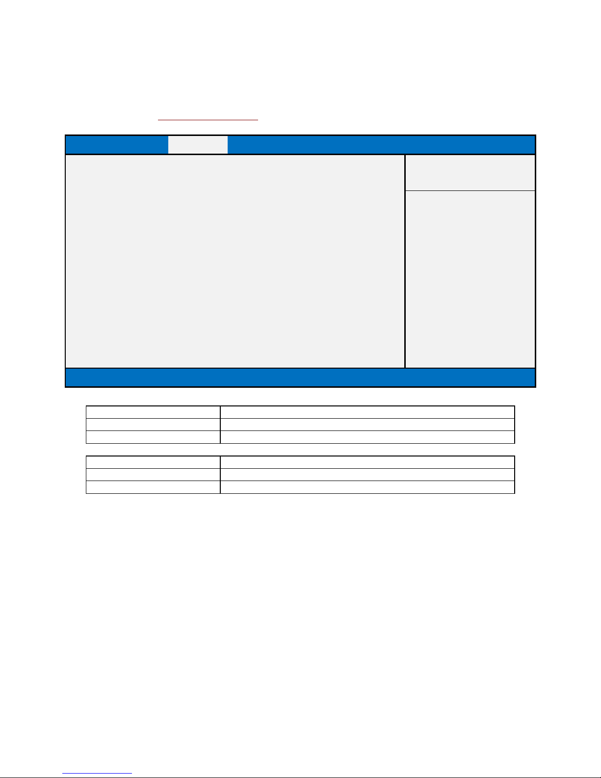
Memory Configuration
Main
Advanced
Chipset
Boot
Security
Save & Exit
Memory Configuration
Item help
Memory Frequency
2133 Mhz
→←: Select Screen
DIMM#1
16384 MB (DDR4)
↑↓: Select Item
DIMM#2
16384 MB (DDR4)
Enter: Select
+/- : Change Opt
F1: General Help
F2: Previous Values
F3: Optimized Defaults
F4: Save & Reset
ESC: Exit
Version 2.18.1264. Copyright (C) 2017 American Megatrends, Inc.
Field Name
Memory Frequency
Help
Memory speed
Comment
This field is not selectable. There is no help text associated with it.
Field Name
DIMM#[1:2]
Help
Memory in the DIMM.
Comment
This field is not selectable. There is no help text associated with it.
Page 43
Graphics Configuration
Main
Advanced
Chipset
Security
Boot
Save & Exit
Graphics Configuration
Item help
DVMT Pre-Allocated
[32M]
→←: Select Screen
DVMT Total Gfx Mem
[256M]
↑↓: Select Item
Enter: Select
+/- : Change Opt
F1: General Help
F2: Previous Values
F3: Optimized Defaults
F4: Save & Reset
ESC: Exit
Version 2.18.1264. Copyright (C) 2017 American Megatrends, Inc.
Field Name
DVMT Pre-Allocated
Default Value
[32M]
Possible Value
32M / 64M / 4M/ 8M/ 12M/ 16M/ 20M/ 24M/ 28M/ (32M/F7)/ 36M/
40M/ 44M/ 48M/ 52M/ 56M/ 60M
Help
Select DVMT 5.0 Pre-Allocated (Fixed) Graphics Memory size used by
the Internal Graphics Device.
Field Name
DVMT Total Gfx Mem
Default Value
[256M]
Possible Value
128MB / 256MB / MAX
Help
Select DVMT5.0 Total Graphic Memory size used by the Internal
Graphics Device.
Page 44
PCH-IO CONFIGURATION
Main
Advanced
Chipset
Security
Boot
Save & Exit
PCH-IO Configuration
Item help
►HD Audio Configuration
→←: Select Screen
↑↓: Select Item
DeepSx Power Policies
[Disabled]
Enter: Select
Wake On LAN
[Enabled]
+/- : Change Opt
State After G3
[S5 State]
F1: General Help
F2: Previous Values
F3: Optimized Defaults
F4: Save & Reset
ESC: Exit
Version 2.18.1264. Copyright (C) 2017 American Megatrends, Inc.
Field Name
HD Audio Configuration
Help
HD Audio Subsystem Configuration Settings
Comment
Press Enter when selected to go into the associated Sub-Menu.
Field Name
DeepSx Power Policies
Default Value
[Disabled]
Possible Value
Enabled in S4-S5
Disabled
Help
configure the DeepSx Mode configuration.
Field Name
Wake On LAN
Default Value
[Enabled]
Possible Value
Enabled
Disabled
Help
Enabled/Disabled integrated LAN to wake the system.
Field Name
State After G3
Default Value
[S5 State]
Possible Value
S0 State
S5 State
Help
Specify what state to go to when power is re-applied after a power
failure (G3 state).
Page 45
HD Audio Configuration
Main
Advanced
Chipset
Boot
Security
Save & Exit
HD Audio Subsystem Configuration Settings
Item help
HD Audio
[Auto]
→←: Select Screen
↑↓: Select Item
Enter: Select
+/- : Change Opt
F1: General Help
F2: Previous Values
F3: Optimized Defaults
F4: Save & Reset
ESC: Exit
Version 2.18.1264. Copyright (C) 2017 American Megatrends, Inc.
Field Name
HD Audio
Value
[Auto]
Possible Value
Auto / Enable / Disable
Help
Control Detection of HD-Audio device.
Disabled = HDA will be unconditionally disabled
Enable = HDA will be unconditionally enabled
Auto = HDA will be enabled if present, disabled otherwise.
Page 46
SECURITY PAGE
Main
Advanced
Chipset
Security
Boot
Save & Exit
Password Description
Item help
If Only the Administrator's password is set,
then this only limits access to Setup and is
only asked for when entering Setup.
If ONLY the User’s password is set, then this
is a power on password and must be entered to
boot or enter Setup. In Setup the User will
have Administrator rights..
The password length must be
in the following range:
Minimum length
3 Maximum length
20
→←: Select Screen
↑↓: Select Item
Administrator Password
Enter: Select
User Password
+/- : Change Opt
F1: General Help
HDD Security Configuration:
F2: Previous Values
HDD Security drive
F3: Optimized Defaults
F4: Save & Reset
►Secure Boot
ESC: Exit
►Secure Flash Update
Version 2.18.1264. Copyright (C) 2017 American Megatrends, Inc.
Field Name
Administrator Password
Help
Set Administrator Password
Field Name
User Password
Help
Set User Password.
Field Name
HDD Security drive
Help
HDD Security Configuration for selected drive
Comment
Press Enter when selected to go into the associated Sub-Menu.
Page 47

Field Name
Secure Boot
Help
Customizable Secure Boot settings
Comment
Press Enter when selected to go into the associated Sub-Menu.
Field Name
Secure Flash Update
Help
Secure Flash Update support
Comment
Press Enter when selected to go into the associated Sub-Menu.
Page 48
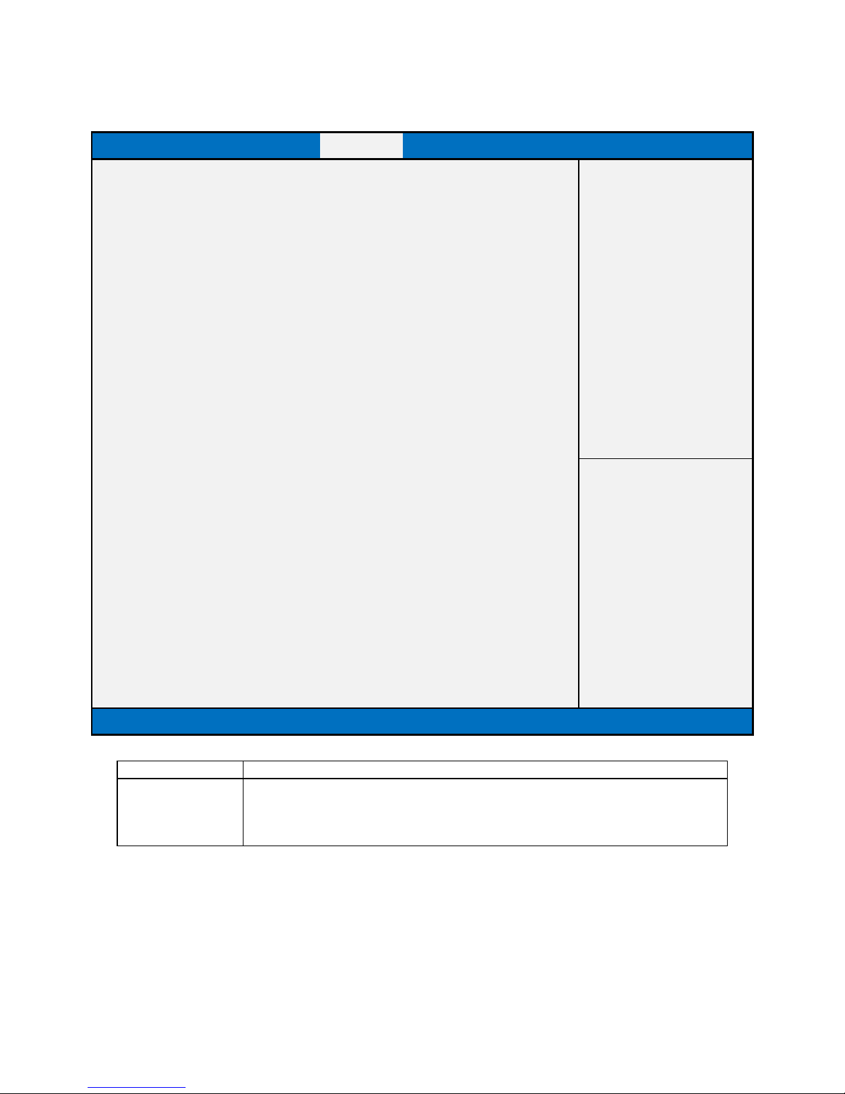
HDD SECURITY
Main
Advanced
Chipset
Security
Boot
Save & Exit
HDD Password Description :
Item help
Allows Access to Set, Modify and Clear
HardDisk User and Master Passwords.
User Password need to be installed for
Enabling Security. Master Password can
be Modified only when successfully unlocked
with Master Password in POST.
If the 'Set HDD Password' option is grayed out,
do power cycle to enable the option again.
HDD PASSWORD CONFIGURATION:
→←: Select Screen
Security Supported :
Yes
↑↓: Select Item
Security Enabled :
No
Enter: Select
Security Locked :
No
+/- : Change Opt
Security Frozen :
No
F1: General Help
HDD User Pwd Status :
NOT INSTALLED
F2: Previous Values
HDD Master Pwd Status :
INSTALLED
F3: Optimized Defaults
F4: Save & Reset
Set User Password
ESC: Exit
Version 2.18.1264. Copyright (C) 2017 American Megatrends, Inc.
Field Name
Set User Password
Help
Set HDD User Password. *** Advisable to Power Cycle System after Setting Hard
Disk Passwords ***.Discard or Save changes option in setup does not have any impact
on HDD when password is set or removed. If the 'Set HDD User Password' option is
grayed out, do power cycle to enable the option again
Page 49
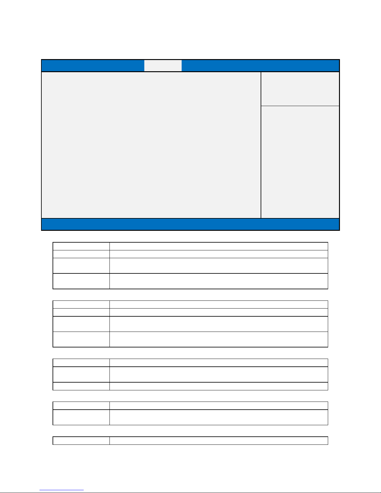
SECURE BOOT
Main
Advanced
Chipset
Security
Boot
Save & Exit
System Mode
Setup
Item help
Vender keys
Not Modified
Secure Boot Enable
[Disabled]
→←: Select Screen
Not Active
↑↓: Select Item
Enter: Select
Secure Boot Mode
[Custom]
+/- : Change Opt
F1: General Help
► Restore Factory Keys
F2: Previous Values
► Reset To Setup Mode
F3: Optimized Defaults
F4: Save & Reset
►Key Management
ESC: Exit
Version 2.18.1264. Copyright (C) 2017 American Megatrends, Inc.
Field Name
Secure Boot Enable
Default Value
[Disabled]
Possible Value
Enabled
Disabled
Help
Secure Boot activated when Platform Key(PK) is enrolled, System mode is
User/Deployed, and CSM function is disabled
Field Name
Secure Boot Mode
Default Value
[Custom]
Possible Value
Standard
Custom
Help
Customizable Secure Boot mode: In Custom mode Secure Boot Policy variables can be
configured by a physically present user without full authentication
Field Name
Key Management
Help
Enables expert users to modify Secure Boot Policy variables without full
authentication
Comment
Press Enter when selected to go into the associated Sub-Menu.
Field Name
Restore Factory Keys
Help
Force System to User Mode. Configure NVRAM to contain OEM-defined factory
default Secure Boot keys
Field Name
Reset to Setup Mode
Page 50

Help
Delete NVRAM content of all UEFI Secure Boot key databases
Page 51
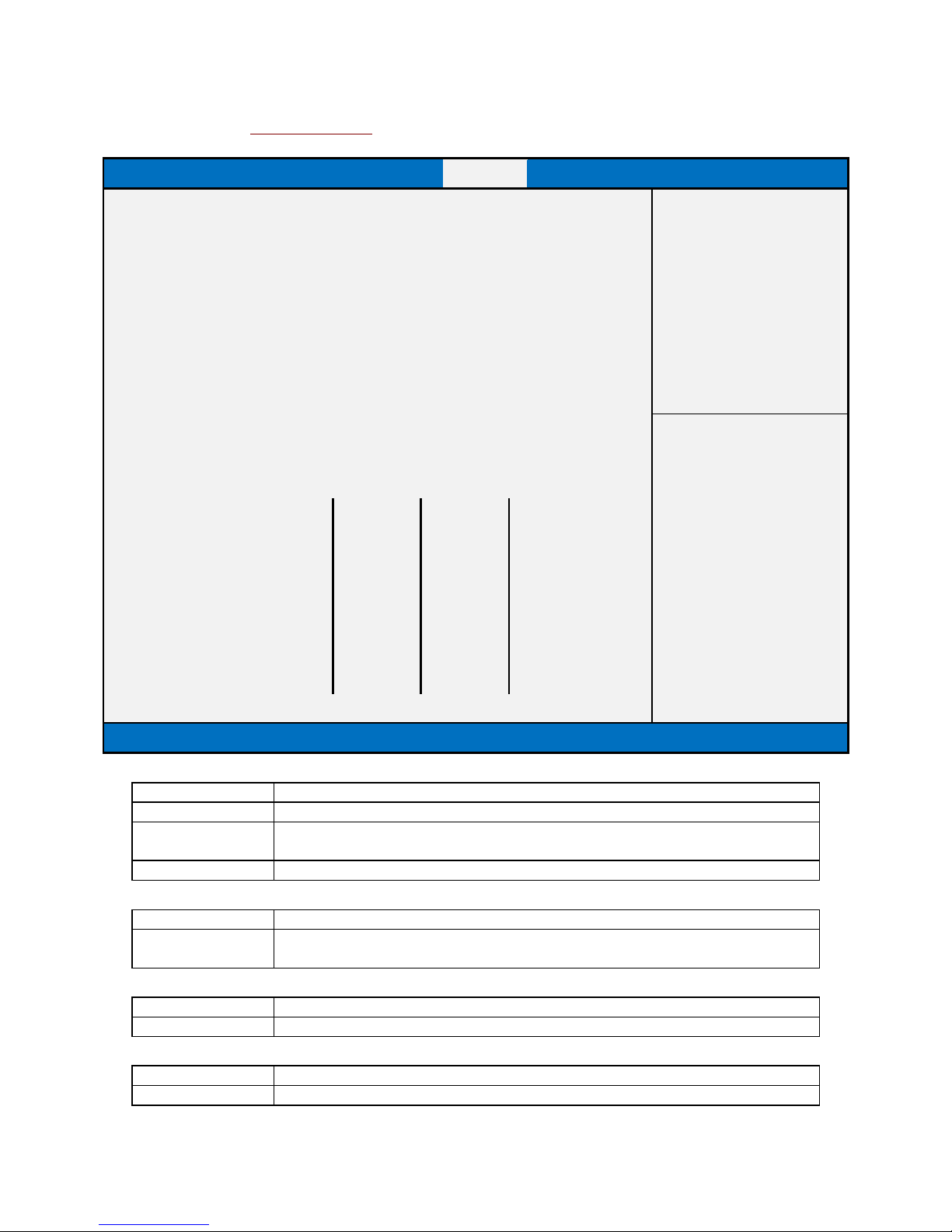
Key Management
Main
Advanced
Chipset
Security
Boot
Save & Exit
Factory Key Provision
[Disabled]
Item help
► Restore Factory Keys
► Reset To Setup Mode
► Export Secure Boot variables
► Enroll Efi Image
► Device Guard ready
► Remove ‘UEFI CA’ from DB
→←: Select Screen
► Restore DB defaults
↑↓: Select Item
Enter: Select
Secure Boot variable
Size
Key#
Key Source
+/- : Change Opt.
► Platform Key(PK)
0 0 No Key
F1: General Help
► Key Exchange Key
0 0 No Key
F2: Previous Values
► Authorized Signatures
0 0 No Key
F3: Optimized Defaults
► Forbidden Signatures
0 0 No Key
F4: Save & Reset
► Authorized TimeStamps
0 0 No Key
ESC: Exit
► OsRecovery Signatures
0 0 No Key
Version 2.18.1264. Copyright (C) 2017 American Megatrends, Inc.
Field Name
Factory Key Provision
Default Value
[Disabled]
Possible Value
Enabled
Disabled
Help
Provision factory default keys on next re-boot only when System in Setup Mode
Field Name
Restore Factory Keys
Help
Force System to User Mode. Configure NVRAM to contain OEM-defined factory
default Secure Boot keys
Field Name
Reset to Setup Mode
Help
Delete NVRAM content of all UEFI Secure Boot key databases
Field Name
Export Secure Boot variables
Help
Copy NVRAM content of Secure Boot variables to files in a root folder on a file
Page 52

system device
Field Name
Enroll Efi Image
Help
Allow the image to run in Secure Boot mode. Enroll SHA256 Hash certificate of a PE
image into Authorized Signature Database (db)
Field Name
Remove ‘UEFI CA’ from DB
Help
Device Guard ready system must not list 'Microsoft UEFI CA' Certificate in
Authorized Signature database (db)
Field Name
Remove DB defaults
Help
Restore DB variable to factory defaults
Field Name
Platform Key (PK)
Default Value
Size:0, Key#:0, Key source: No Key
Help
Enroll Factory Defaults or load certificates from a file:
1.Public Key Certificate in:
a)EFI_SIGNATURE_LIST
b)EFI_CERT_X509 (DER encoded)
c)EFI_CERT_RSA2048 (bin)
d)EFI_CERT_SHA256,384,512
2.Authenticated UEFI Variable
3.EFI PE/COFF Image(SHA256)
Key Source:
Factory,External,Mixed
comment
Press Enter when selected to go into the associated Sub-Menu “Key Management”.
Field Name
Key Exchange Key
Default Value
Size:0, Key#:0, Key source: No Key
Help
Enroll Factory Defaults or load certificates from a file:
1.Public Key Certificate in:
a)EFI_SIGNATURE_LIST
b)EFI_CERT_X509 (DER encoded)
c)EFI_CERT_RSA2048 (bin)
d)EFI_CERT_SHA256,384,512
2.Authenticated UEFI Variable
3.EFI PE/COFF Image(SHA256)
Key Source:
Factory,External,Mixed
comment
Press Enter when selected to go into the associated Sub-Menu.
Field Name
Authorized Signature
Default Value
Size:0, Key#:0, Key source: No Key
Help
Enroll Factory Defaults or load certificates from a file:
1.Public Key Certificate in:
a)EFI_SIGNATURE_LIST
b)EFI_CERT_X509 (DER encoded)
Page 53

c)EFI_CERT_RSA2048 (bin)
d)EFI_CERT_SHA256,384,512
2.Authenticated UEFI Variable
3.EFI PE/COFF Image(SHA256)
Key Source:
Factory,External,Mixed
comment
Press Enter when selected to go into the associated Sub-Menu.
Field Name
Forbidden Signature
Default Value
Size:0, Key#:0, Key source: No Key
Help
Enroll Factory Defaults or load certificates from a file:
1.Public Key Certificate in:
a)EFI_SIGNATURE_LIST
b)EFI_CERT_X509 (DER encoded)
c)EFI_CERT_RSA2048 (bin)
d)EFI_CERT_SHA256,384,512
2.Authenticated UEFI Variable
3.EFI PE/COFF Image(SHA256)
Key Source:
Factory,External,Mixed
comment
Press Enter when selected to go into the associated Sub-Menu.
Field Name
Authorized TimeStamps
Default Value
Size:0, Key#:0, Key source: No Key
Help
Enroll Factory Defaults or load certificates from a file:
1.Public Key Certificate in:
a)EFI_SIGNATURE_LIST
b)EFI_CERT_X509 (DER encoded)
c)EFI_CERT_RSA2048 (bin)
d)EFI_CERT_SHA256,384,512
2.Authenticated UEFI Variable
3.EFI PE/COFF Image(SHA256)
Key Source:
Factory,External,Mixed
comment
Press Enter when selected to go into the associated Sub-Menu.
Field Name
OsRecovery Signatures
Default Value
Size:0, Key#:0, Key source: No Key
Help
Enroll Factory Defaults or load certificates from a file:
1.Public Key Certificate in:
a)EFI_SIGNATURE_LIST
b)EFI_CERT_X509 (DER encoded)
c)EFI_CERT_RSA2048 (bin)
d)EFI_CERT_SHA256,384,512
2.Authenticated UEFI Variable
3.EFI PE/COFF Image(SHA256)
Key Source:
Factory,External,Mixed
comment
Press Enter when selected to go into the associated Sub-Menu.
Page 54

Page 55
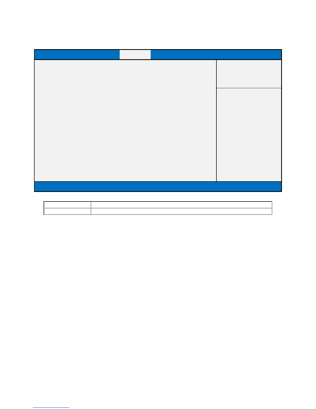
SECURE FLASH UPDATE
Main
Advanced
Chipset
Security
Boot
Save & Exit
►Path for ROM Image
Item help
Notice :
ROM Image must in the root folder of storage device.
→←: Select Screen
File name must match with current BIOS project.
↑↓: Select Item
Enter: Select
+/- : Change Opt
F1: General Help
F2: Previous Values
F3: Optimized Defaults
F4: Save & Reset
ESC: Exit
Version 2.18.1264. Copyright (C) 2017 American Megatrends, Inc.
Field Name
Path for ROM Image
Help
Enter the path to the Secure flash option
Page 56
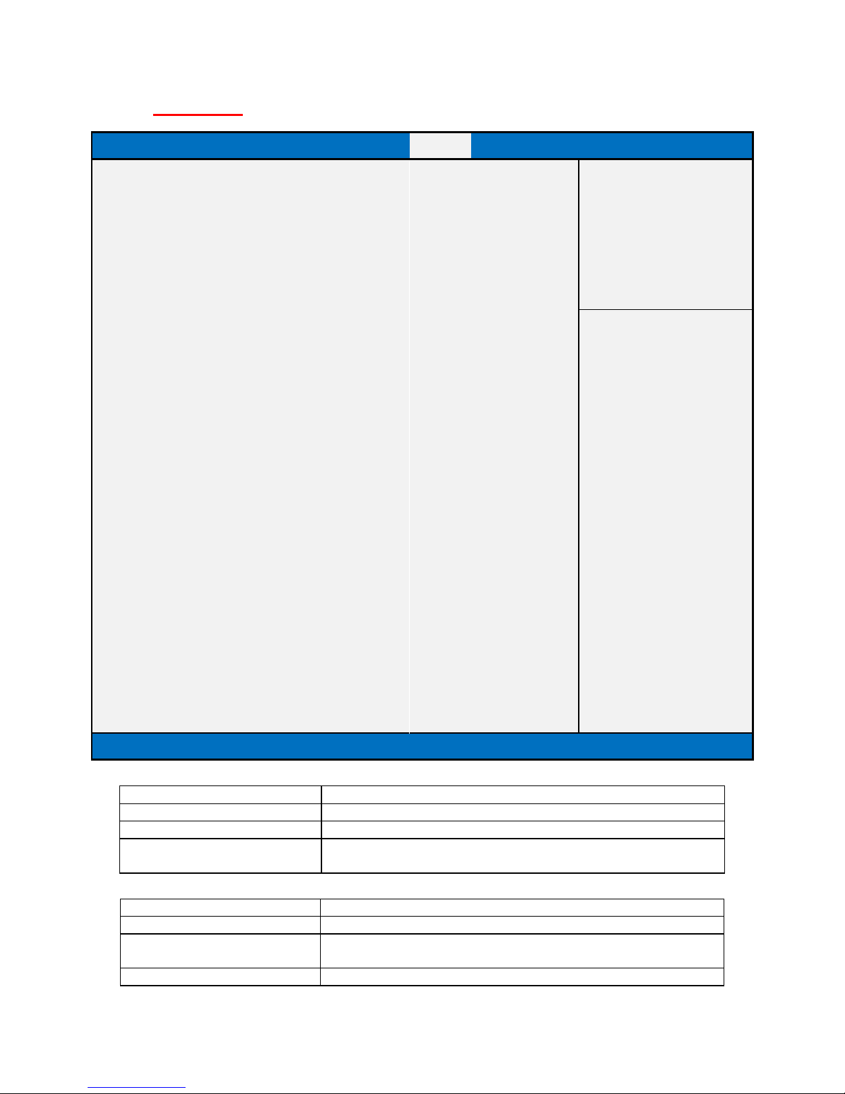
BOOT PAGE
Main
Advanced
Chipset
Security
Boot
Save & Exit
Boot Configuration
Item help
Setup Prompt Timeout
1 Bootup NumLock State
[On]
Boot Mode Select
[UEFI]
FIXED BOOT ORDER Priorities
→←: Select Screen
Boot Option #1
[USB Floppy]
↑↓: Select Item
Boot Option #2
[USB CD/DVD]
Enter: Select
Boot Option #3
[Hard Disk]
+/- : Change Opt.
Boot Option #4
[USB Key]
F1: General Help
Boot Option #5
[USB Hard Disk]
F2: Previous Values
Boot Option #6
[USB Lan]
F3: Optimized Defaults
Boot Option #7
[Network]
F4: Save & Reset
ESC: Exit
►(UEFI) USB Floppy Drive BBS Priorities
►(UEFI) USB CD/DVD Drive BBS Priorities
►(UEFI) Hard Disk Drive BBS Priorities
►(UEFI) USB Key Drive BBS Priorities
►(UEFI) USB Hard Disk Drive BBS Priorities
►(UEFI) USB Lan Drive BBS Priorities
►(UEFI) Network Drive BBS Priorities
Version 2.18.1264. Copyright (C) 2017 American Megatrends, Inc.
Field Name
Setup Prompt Timeout
Default Value
1
Possible Value
1~65535
Help
Number of seconds to wait for setup activation key. 65535(0xFFFF)
means indefinite waiting.
Field Name
Bootup NumLock State
Default Value
[On]
Possible Value
On
Off
Help
Select the keyboard NumLock state
Page 57

Field Name
Boot Mode Select
Default Value
[UEFI]
Possible Value
LEGACY (Support Skylake series for Win7)
UEFI
Help
Select boot mode LEGACY/UEFI
Field Name
Boot Option #1
Default Value
[USB Floppy]
Possible Value
Hard Disk, USB Hard Disk, USB CD/DVD, USB Key, USB Floppy ,
USB Lan, Network
Help
Sets the system boot order
Field Name
Boot Option #2
Default Value
[USB CD/DVD]
Possible Value
Hard Disk, USB Hard Disk, USB CD/DVD, USB Key, USB Floppy ,
USB Lan, Network
Help
Sets the system boot order
Field Name
Boot Option #3
Default Value
[Hard Disk]
Possible Value
Hard Disk, USB Hard Disk, USB CD/DVD, USB Key, USB Floppy ,
USB Lan, Network
Help
Sets the system boot order
Field Name
Boot Option #4
Default Value
[USB Key]
Possible Value
Hard Disk, USB Hard Disk, USB CD/DVD, USB Key, USB Floppy ,
USB Lan, Network
Help
Sets the system boot order
Field Name
Boot Option #5
Default Value
[USB Hard Disk]
Possible Value
Hard Disk, USB Hard Disk, USB CD/DVD, USB Key, USB Floppy ,
USB Lan, Network
Help
Sets the system boot order
Field Name
Boot Option #6
Default Value
[USB Lan]
Possible Value
Hard Disk, USB Hard Disk, USB CD/DVD, USB Key, USB Floppy ,
USB Lan, Network
Help
Sets the system boot order
Field Name
Boot Option #7
Default Value
[Network]
Possible Value
Hard Disk, USB Hard Disk, USB CD/DVD, USB Key, USB Floppy ,
USB Lan, Network
Page 58

Help
Sets the system boot order
Field Name
(UEFI) USB Floppy Drive BBS Priorities
Help
Specifies the Boot Device Priority sequence from available USB Floppy
Drives.
Comment
Press Enter when selected to go into the associated Sub-Menu.
Field Name
(UEFI) USB CD/DVD ROM Drive BBS Priorities
Help
Specifies the Boot Device Priority sequence from available USB
CDROM/DVD Drives.
Comment
Press Enter when selected to go into the associated Sub-Menu.
Field Name
(UEFI) USB Hard Disk Drive BBS Priorities
Help
Specifies the Boot Device Priority sequence from available USB Hard
Disk Drives.
Comment
Press Enter when selected to go into the associated Sub-Menu.
Field Name
(UEFI) USB KEY Drive BBS Priorities
Help
Specifies the Boot Device Priority sequence from available USB Key
Drives.
Comment
Press Enter when selected to go into the associated Sub-Menu.
Field Name
(UEFI) Hard Disk Drive BBS Priorities
Help
Specifies the Boot Device Priority sequence from available Hard Disk
Drives.
Comment
Press Enter when selected to go into the associated Sub-Menu.
Field Name
(UEFI) NETWORK Drive BBS Priorities
Help
Specifies the Boot Device Priority sequence from available NETWORK
Drives.
Comment
Press Enter when selected to go into the associated Sub-Menu.
Page 59
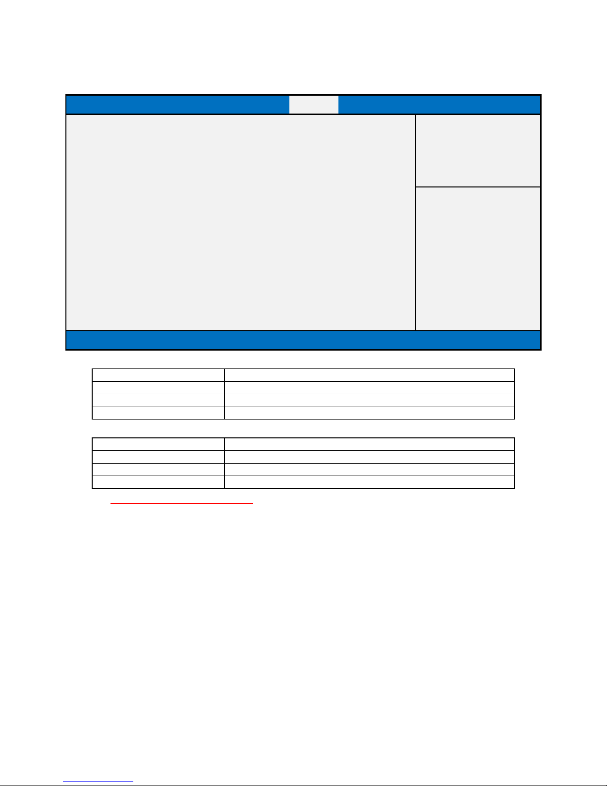
(LIST BOOT DEVICE TYPE) DRIVE BBS PRIORITIES
Main
Advanced
Chipset
Security
Boot
Save & Exit
Boot Option #1
[Boot Device Name 1]
Item help
Boot Option #2
[Boot Device Name 2]
→←: Select Screen
↑↓: Select Item
Enter: Select
+/- : Change Opt
F1: General Help
F2: Previous Values
F3: Optimized Defaults
F4: Save & Reset
ESC: Exit
Version 2.18.1264. Copyright (C) 2017 American Megatrends, Inc.
Field Name
Boot Option #1
Default Value
Possible Value
Boot Device Name 1 of this type
Help
Sets the system boot order
Field Name
Boot Option #2
Default Value
Possible Value
Boot Device Name 2 of this type
Help
Sets the system boot order
Page 60
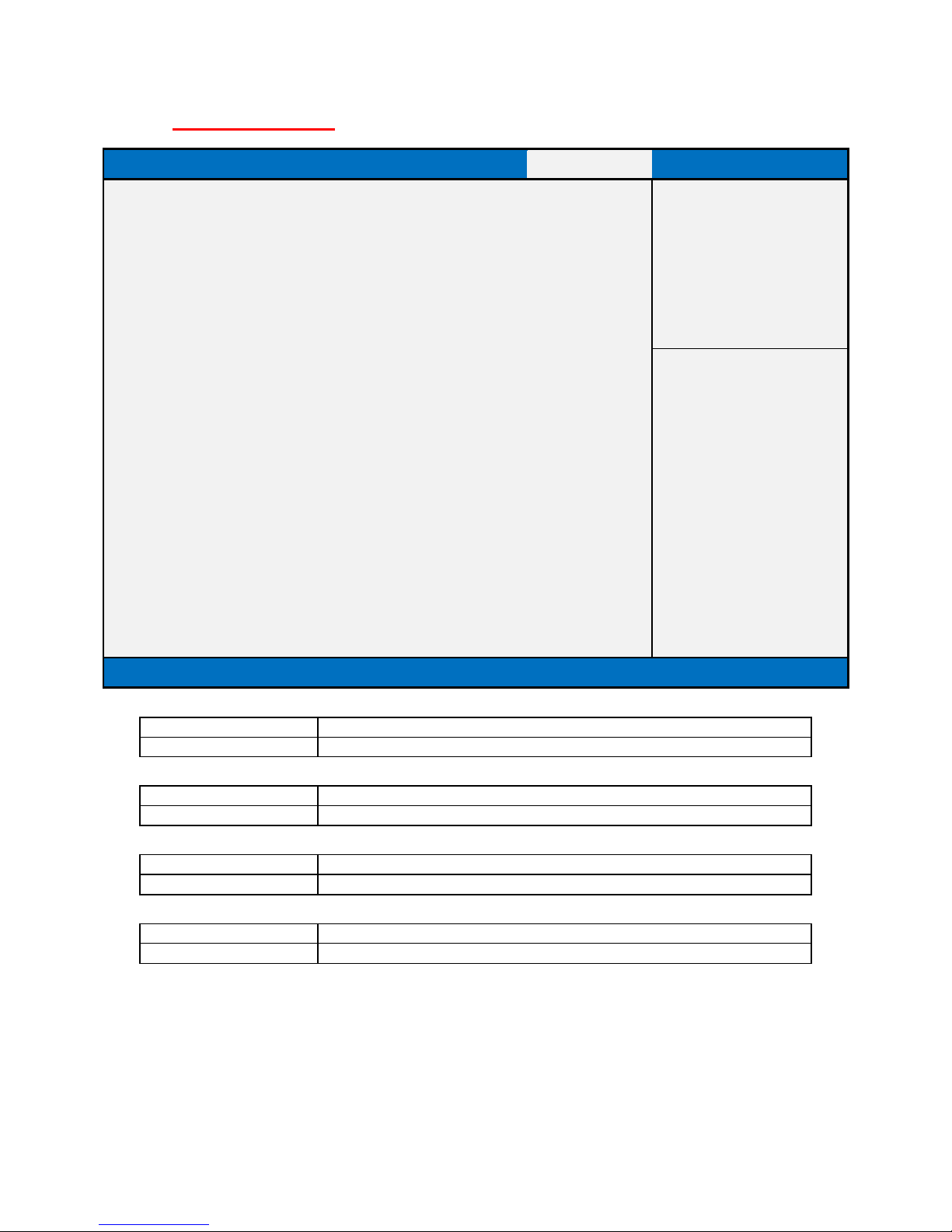
SAVE & EXIT PAGE
Main
Advanced
Chipset
Security
Boot
Save & Exit
Save Options
Item help
Discard Changes and Exit
Save Changes and Reset
Discard Changes and Reset
Restore Defaults
→←: Select Screen
↑↓: Select Item
Enter: Select
+/- : Change Opt
F1: General Help
F2: Previous Values
F3: Optimized Defaults
F4: Save & Reset
ESC: Exit
Version 2.18.1264. Copyright (C) 2017 American Megatrends, Inc.
Field Name
Discard Changes and Exit
Help
Exit system setup with without saving any changes.
Field Name
Save Changes and Reset
Help
Reset the system after saving the changes.
Field Name
Discard Changes and Rest
Help
Reset system setup without saving any changes.
Field Name
Restore Defaults
Help
Restore/Load Legacy Default values for all the setup options.
Page 61
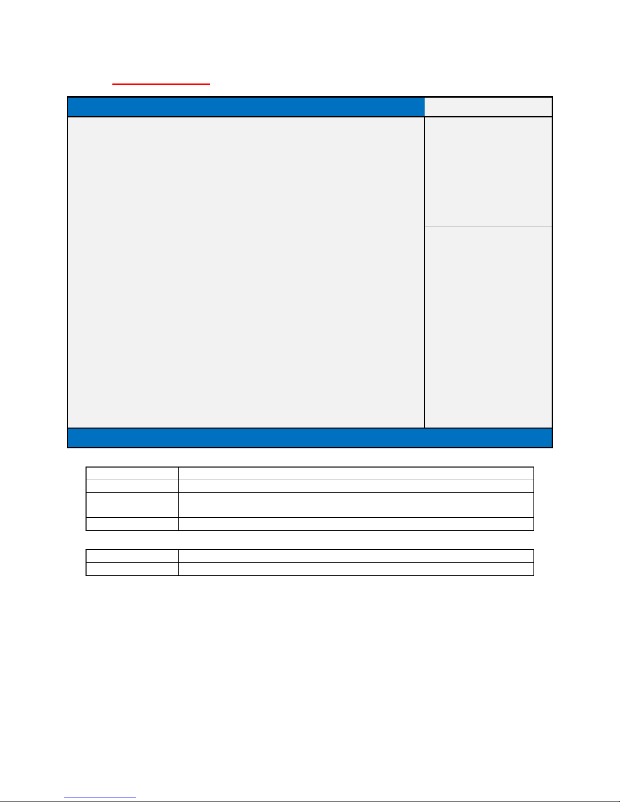
RECOVERY PAGE (ACTIVE FOR SECURE FLASH UPDATE ONLY)
Main
Advanced
Chipset
Security
Boot
Save & Exit
Recovery
Please select block you want to update
Item help
Reset NVRAM
[Disabled]
►Process with flash update
→←: Select Screen
↑↓: Select Item
Enter: Select
+/- : Change Opt
F1: General Help
F2: Previous Values
F3: Optimized Defaults
F4: Save & Reset
ESC: Exit
Version 2.18.1264. Copyright (C) 2017 American Megatrends, Inc.
Field Name
Reset NVRAM
Default Value
[Disabled]
Possible Value
Enabled
Disabled
Help
Set this option to reset NVRAM to default values
Field Name
Process with flash update
Help
Select this to start flash update
 Loading...