

Page 1

MITAC Desktop Board PH12LI
Product Guide
Page 2

Desktop Board Features
This chapter briefly describes the features of Desktop Board PH12LI.
Table 1 summarizes the major features of the Desktop Board.
Feature Summary
T
AB L E
1. MITA C D
Low-profile Mini-ITX (20 millimeters [0.79 inches] x 170.18
Form Factor
Processor
Chipset Intel Lynx Point Q87 Chipset
Memory
millimeters
[6.7 inches] x 170.18 millimeters [6.7 inches])
Intel Haswell H3 LGA1150 CPU Socket
Support up to Dual/Quad core 65W
Support for DDR3 1066/1333/1600 MHz SO-DIMMs
Support for up to 16 GB of system memory
ES K T O P BOA R D
PH12LI F
EA T U RES
Display
Audio
Expansion
Capability
204-pin DDR3 SO-DIMM 2
HD-out connector
40P Embedded LVDS connector
RealTek* ALC888 audio codec for 7.1 (8-channel) High
Definition Audio (HD Audio) Included are:
Back panel audio connectors: Line-out & Mic
1 x Audio header for stereo speakers
1 x Audio header for front Panel Mic/Hp
1 x Audio header for DMIC
PCI Express x 4 slot 1
PCI Express Full-/Half-Mini Card slot 1
PCI Express Half-Mini Card slot 1
2
Page 3

pin CPU fan
USB 2.0 front panel ports
Peripheral
Interfaces
Legacy I/O Legacy I/O Controller (NCT6683D)
Security
LAN Support
BIOS
Serial port header 2
SATA 3.0 Gb/s 4
Intel® vPro™ Technology support
TPM security by Nuvoton NPCT420AA0WX(optional)
Intel Clarkville I217-LM/I210-AT Gigabit (10/100/1000 Mb/s) IC
Dual Ethernet LAN controller including an RJ-45 back panel
connector with integrated status LEDs
UEFI Bios
64+32Mb Dual SPI
3
(Headers)
Instantly
Available PC
Technology
Hardware
Monitor
Subsystem
Power
Requirement
Environment
Support for Advanced Configuration and Power Interface
(ACPI) setting
Suspend to RAM support
Wake on PCI Express, LAN, front panel, serial, and USB ports
Hardware monitoring through the Nuvoton6683D legacy I/O
controller, including:
Remote thermal sensor
Speed control for 4-pin system fan header and 4-
header
12/19V DC connectivity via back-panel DC jack Optional: 1 x
standard ATX PSU 4-pin 12 connector
Operating Temperature: 0°C to +50°C
Storage Temperature: -20°C to +70°C
3
Page 4
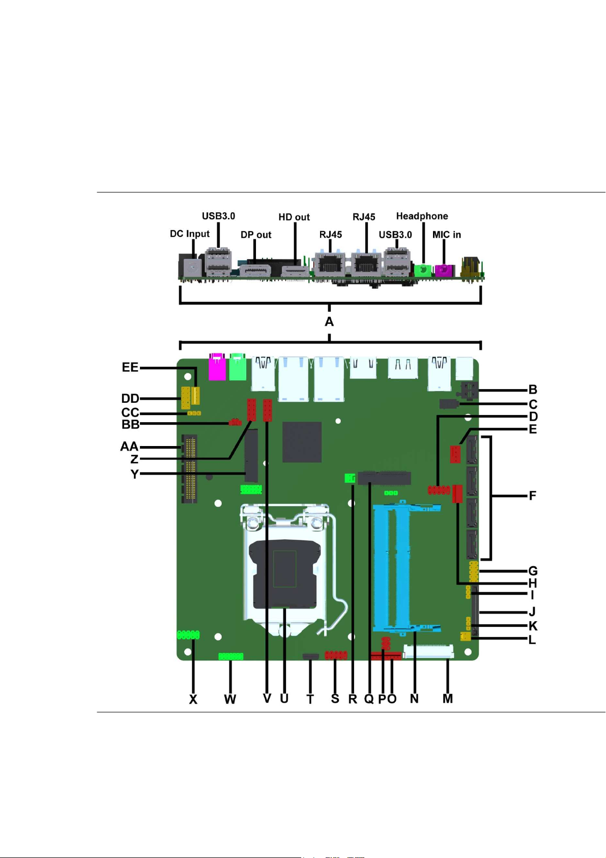
Desktop Board Components
Figure 1 shows the approximate location of the major components on the top side of
MiTAC Desktop Board PH12LI.
Figu re 1 . MiT A C D es k t o p Bo a r d PH 12LI C o m p on e nts ( T op)
4
Page 5

A Back
P
anel
C
onnectors
B DC Power header(12V)
C DC Power header(19V)
D Front dual USB2.0
header
E System FAN
header
F SATA connector
G Front Panel Connector
H CPU FAN
header
I Alternate Power LED
header
J SATA power header
K B
acklight power select
L PANEL
backlight switch
header
M LVDS connector
N DIMM sockets
O Converter board (Brightness
control)
P Panel power select
Q Mini_PCIE
slot
(10mm h
e
ight)
R Chassis intrusion header
S Front dual USB2.0 header
T NFC Connector
U CPU socket
V Serial port
header
W Custom Solutions Header
X Front dual USB2.0 header
Y Mini_PCIE
slot
Z Serial
port header
AA PCI Express X4 Connector
BB Battery connection
CC MEBX Reset header
DD Front Audio header
EE Internal Speaker
T
AB L E
2. MITA C D
ES K T OP BOA R D
PH12LI C
OM P O NENTS
( S
HO W N IN FIG U R E
1 )
5
Page 6

Processor
The board supports 4th generation Intel Core processors. Other processors may be
supported in the future. This board supports processors with a maximum wattage of
65 W Thermal Design Power (TDP).
NOTE
This board has specific requirements for providing power to the processor. Additional
power required will depend on configurations chosen by the integrator.
System Memory
NOTE
To be fully compliant with all applicable DDR SDRAM memory specifications, the board
should be populated with DIMMs that support the Serial Presence Detect (SPD) data
structure. This allows the BIOS to read the SPD data and program the chipset to
accurately configure memory settings for optimum performance. If non-SPD memory
is installed, the BIOS will attempt to correctly configure the memory settings, but
performance and reliability may be impacted or the DIMMs may not function under the
determined frequency.
The Desktop Board has tw o204-pin DDR3 SO-DIMM sockets with gold-plated contacts.
These sockets support:
Support for DDR3 1066/1333/1600 MHz SO-DIMMs
Serial Presence Detect (SPD) memory only
Non-ECC memory
Up to 16 GB of memory
6
Page 7
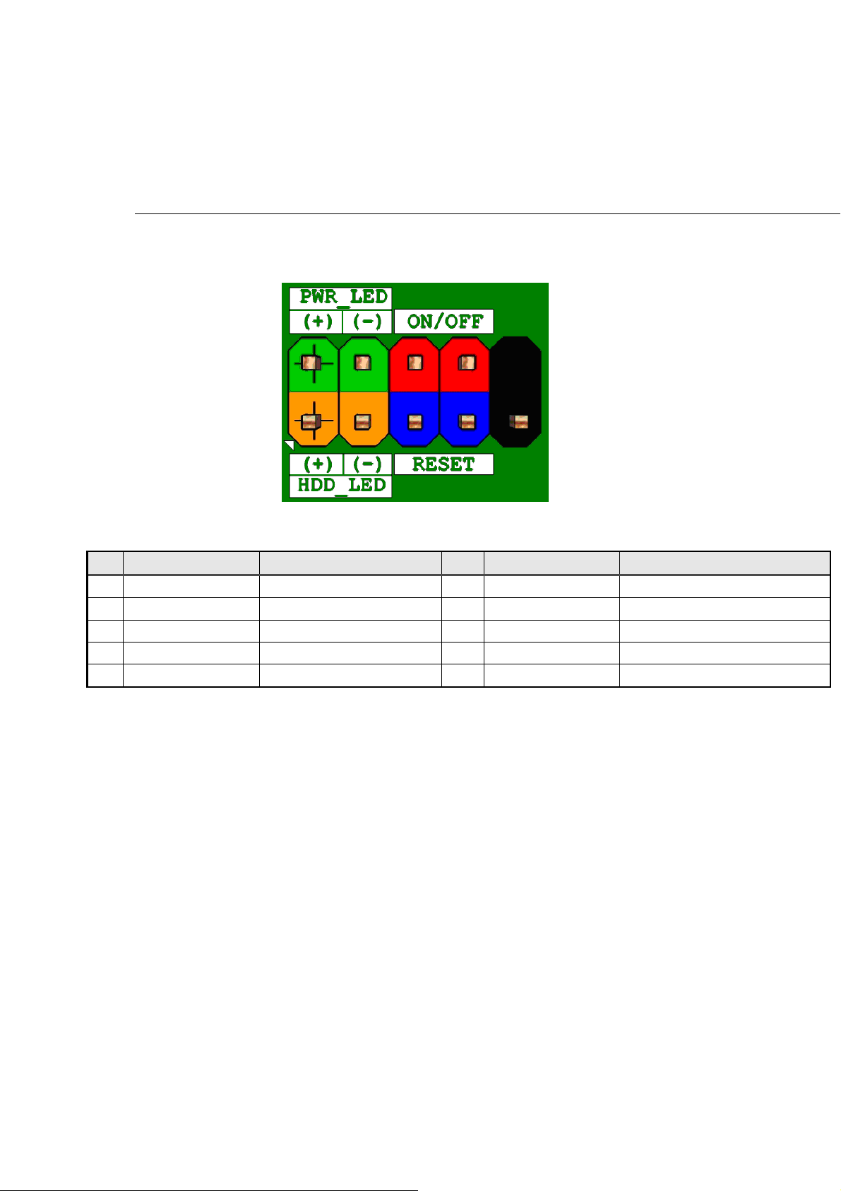
Connecting to the Internal Headers and Connectors
Front panel main header
Figure 2 Front pan el mai n h e a der pi n -ou t
Pin Signal Name Description Pin Signal Name Description
1 HDD_POWER_LED Pull-up resistor (750) to +5V 2 POWER_LED_MAIN [Out] Front panel LED (main color)
3 HDD_LED# [Out] Hard disk activity LED 4 POWER_LED_ALT [Out] Front panel LED (alt color)
5 GROUND Ground 6 POWER_SWITCH# [In] Power switch
7 RESET_SWITCH# [In] Reset switch 8 GROUND Ground
9 +5V_DC Power 10 KEY No pin
T
AB L E 2 FRO N T PANE L MAIN H EADE R SIGNA L S
7
Page 8

Chassis Intrusion Detection Header
The chassis intrusion detection header must be 1x2, 2.54mm pitch, colored black
and with extended back, as defined in below
Figure 3 Chassi s i ntr u s ion detec t i on h e ader
Pin Signal Name
1
2 Ground
i
Intrusion Detection
T
AB L E 3 CHA S S I S INT R U SION DETE C T I ON H E A DER S I G NALS
HD Audio front panel audio header
Figure 4 HD Au di o fr o n t p a nel a u di o h ea d e r p i n -ou t di a g r am
8
Page 9

Pin Signal name Description
1 PORT 1L Analog Port 1 - Left channel (Microphone)
2 GND Ground
3 PORT 1R Analog Port 1 - Right channel (Microphone)
Active low signal that signals BIOS that an Intel® HD Audio dongle is connected
to the analog header. PRESENCE# = 0 when an Intel® HD Audio dongle is
4 PRESENCE#
connected.
5 PORT 2R Analog Port 2 - Right channel (Headphone)
6 SENSE1 RETURN Jack detection return for front panel (JACK1)
Jack detection sense line from the Intel® HD Audio CODEC jack detection
7 SENSE SEND
resistor network
8 KEY No pin
9 PORT 2L Analog Port 2 - Left channel (Headphone)
10 SENSE2 RETURN Jack detection return for front panel (JACK2)
T
AB L E 4 HD AUD I O FRON T PANE L AUDI O HEAD E R
9
Page 10
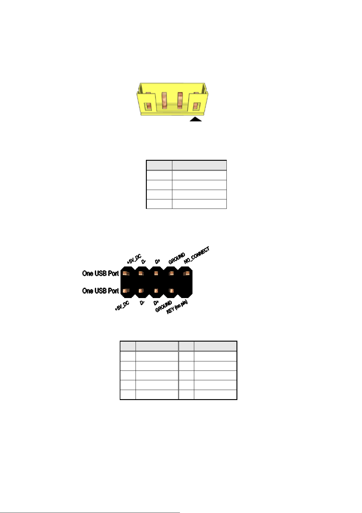
Internal Speaker header
Figure 5 Internal S p e a ker h e a d er pi n - out di a gra m
Pin Signal Name
1
2
3
4
T
AB L E 5 INT E R N AL SPE K A ER HE A D ER
Front_LFront_L+
Front_R+
Front_R-
Front panel US B header
Fi gur e 6 Fr o n t pan e l U SB he a d e r pi n - o u t
Pin Signal Pin Signal
1 +5V DC 2 +5V DC
3 Data (negative) 4 Data (negative)
5 Data (positive) 6 Data (positive)
7 Ground 8 Ground
9 Key (no pin) 10 No Connect
T
AB L E 6 FRON T PANE L
USB
H E ADER S I G NALS
10
Page 11
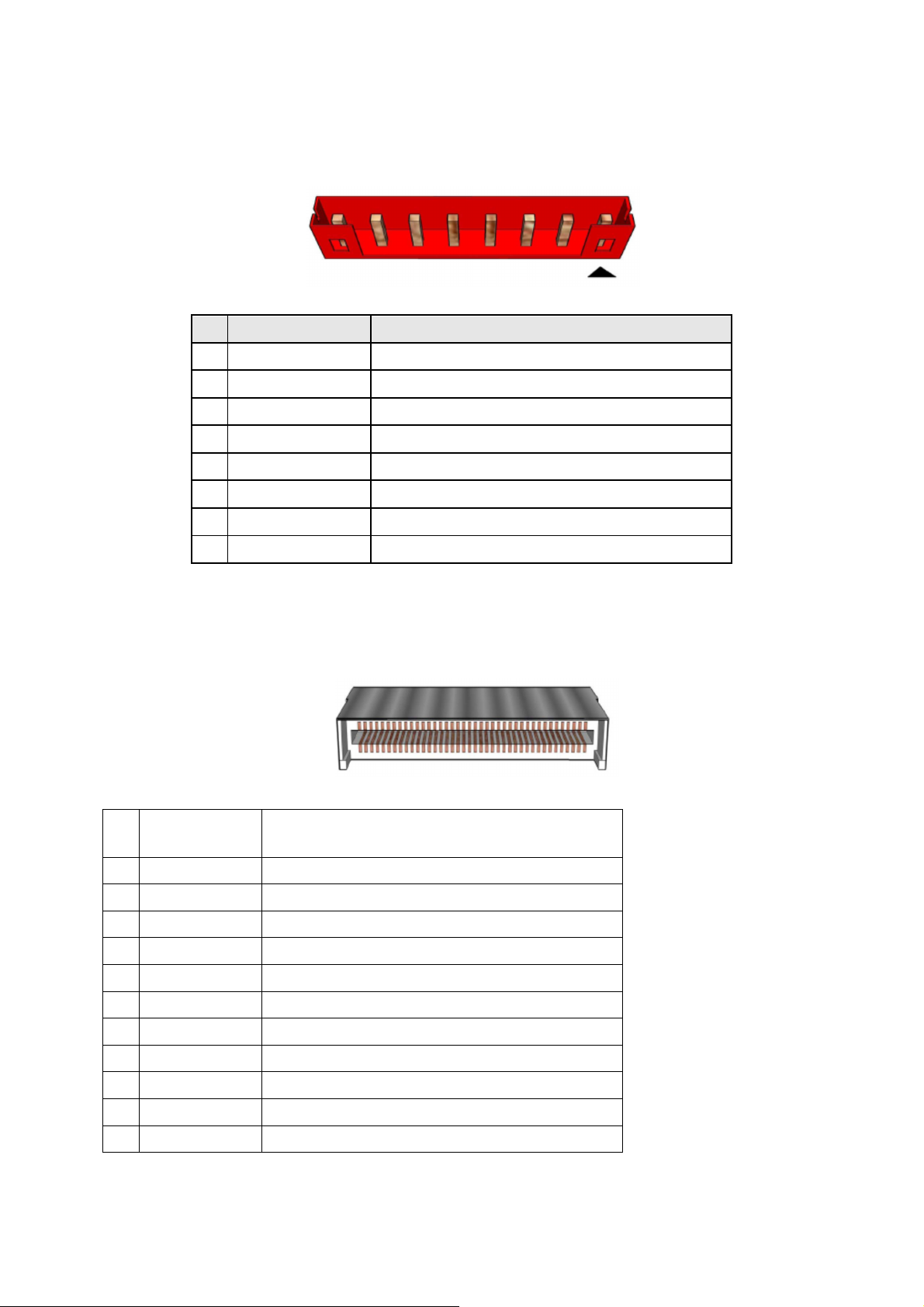
LVDS inverter power header
Fi g u re 7 L VD S i n v e r t e r p ow e r he a der
Pin Signal Name Description
1 BKLT_EN Backlight enable
2 BKLT_PWM Backlight PWM control
3 12V/19V Inverter power
4 12V/19V Inverter power
5 GND Ground
6 GND Ground
7 BRIGHTNESS_UP BRIGHTNESS UP
8 BRIGHTNESS_DOWN BRIGHTNESS DOWN
T
AB L E 7 8-PI N
LV DS
I N VERTE R POWER H EADER PIN-OU T REFER E NCE
LVDS data header
Fi g u re 8 L VD S d a t a h ea d er
Signal Description
Pin
1 LA_DATAP3 LVDS Channel A diff data output - positive
2 LA_DATAN3 LVDS Channel A diff data output - negative
3 LA_DATAP2 LVDS Channel A diff data output - positive
4 LA_DATAN2 LVDS Channel A diff data output - negative
5 LA_DATAP1 LVDS Channel A diff data output - positive
6 LA_DATAN1 LVDS Channel A diff data output - negative
7 LA_DATAP0 LVDS Channel A diff data output - positive
8 LA_DATAN0 LVDS Channel A diff data output - negative
9 LB_DATAP3 LVDS Channel B diff data output-positive
10 LB_DATAN3 LVDS Channel B diff data output-negative
11 LB_DATAP2 LVDS Channel B diff data output-positive
11
Page 12

12 LB_DATAN2 LVDS Channel B diff data output-negative
13 LB_DATAP1 LVDS Channel B diff data output-positive
14 LB_DATAN1 LVDS Channel B diff data output-negative
15 LB_DATAP0 LVDS Channel B diff data output-positive
16 LB_DATAN0 LVDS Channel B diff data output-negative
17 GND Ground
18 3.3V/5V/12V Selectable LCD power output
19 3.3V/5V/12V Selectable LCD power output
20 3.3V/5V/12V Selectable LCD power output
21 NC NC
22 EDID_3.3V VCC3
23 GND Ground
24 GND Ground
25 GND Ground
26 LA_CLKP LVDS Channel A diff data output - positive
27 LA_CLKN LVDS Channel A diff data output - negative
28 GND Ground
29 GND Ground
30 GND Ground
31 EDID_CLK EDID/DDC clock signal
32 BKLT_EN
33 BKLT_CTRL
34 LB_CLKP LVDS Channel B diff data output - positive
35 LB_CLKN LVDS Channel B diff data output - negative
36 BKLT_PWR Selectable BKLT power output
37 BKLT_PWR Selectable BKLT power output
38 BKLT_PWR Selectable BKLT power output
39 NC NC
40 EDID_DATA EDID/DDC data signal
T
AB L E 8
40-
PI N
LVDS
D A T A HEAD E R PI N-OU T REFE R E NCE
12
Page 13
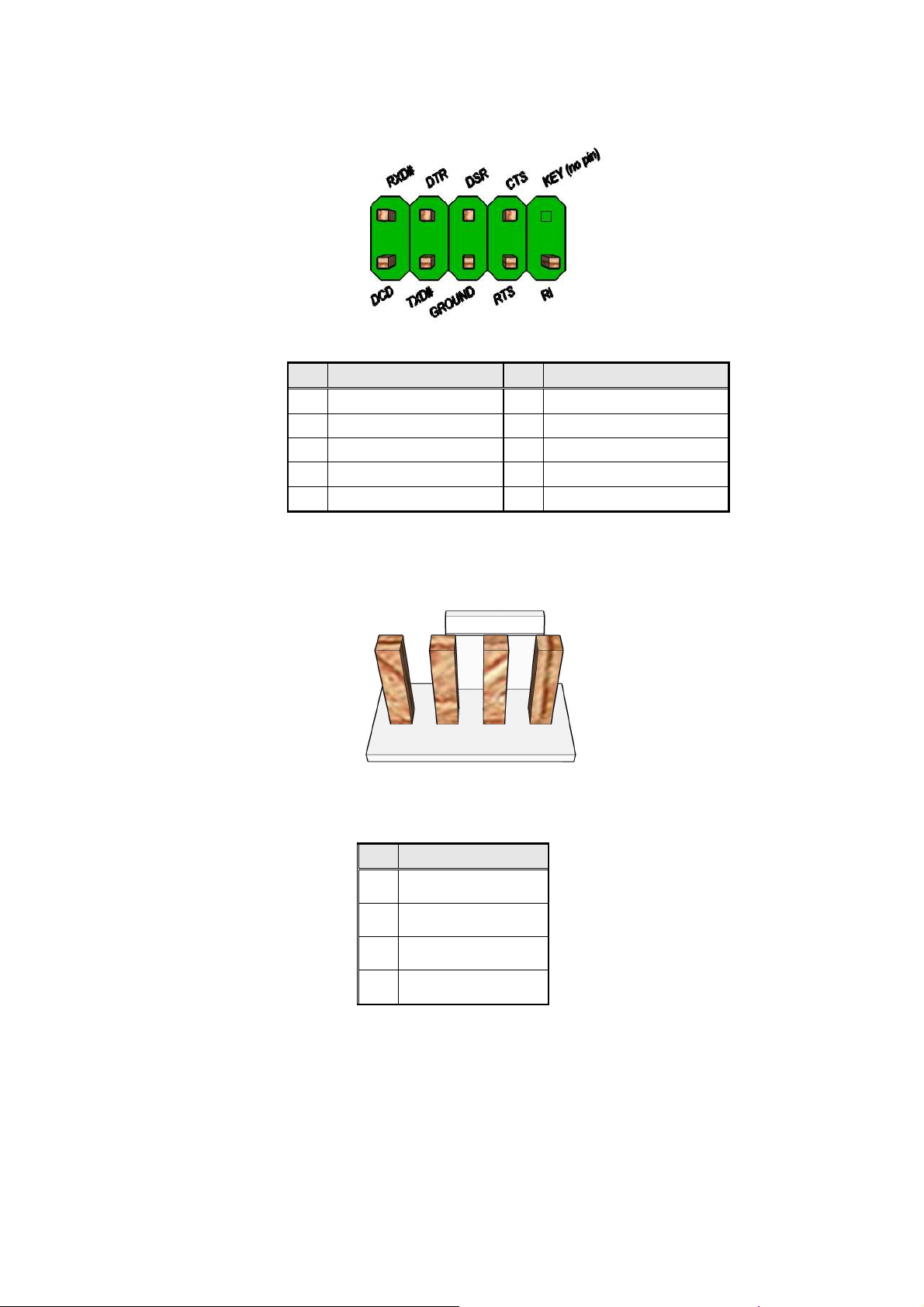
Serial port header
Fi g u re 9 S e r i al por t h e a der pi n-o u t
Pin Signal Pin Signal
1 DCD (Data Carrier Detect) 2 RXD# (Receive Data)
3 TXD# (Transmit Data) 4 DTR (Data Terminal Ready)
5 Ground 6 DSR (Data Set Ready)
7 RTS (Request To Send) 8 CTS (Clear To Send)
9 RI (Ring Indicator) 10 Key (no pin)
T
AB L E 9 SER I A L PORT H E ADE R S IGNAL S
Processor fan header
Figu re 1 0 : P roc e s s or fa n h e a der
Pin Signal
4
3
2
1
T
AB L E
10: P
FAN_CTRL
FAN_TACH
VCC-12V
GND
ROC E S S OR FA N HEAD E R
13
Page 14
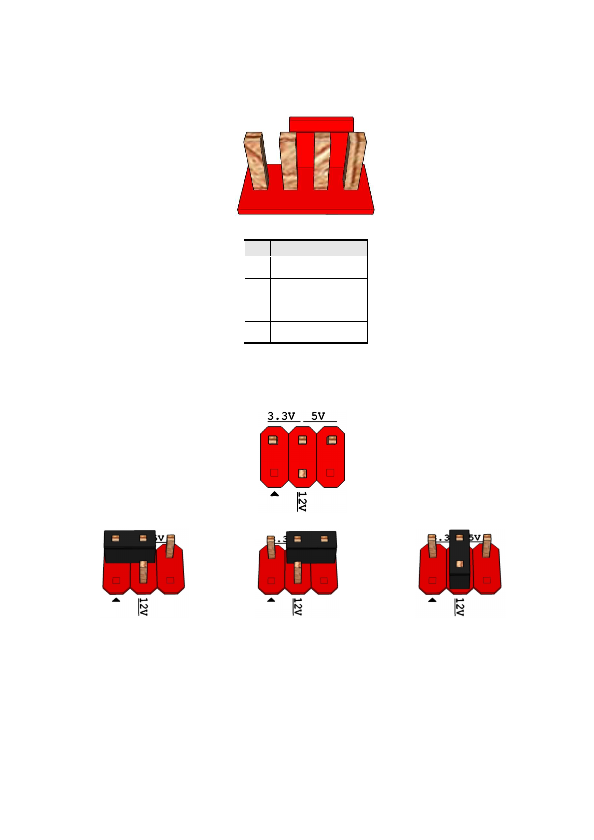
System fan header
Figure 11: System f a n he a d e r
Pin Signal
4
3
2
1
T
AB L E
11: S
FAN_CTRL
FAN_TACH
VCC-12V
GND
YS T E M FAN H EADE R
Panel voltage selection header
Pins 2&4: jumper position for 3.3V Pins 6&4: jumper position for 5V Pins 3&4: jumper position for 12V
Fi gur e 1 2 : L VD S p an el v oltag e sele c t i on h e a d e r
14
Page 15
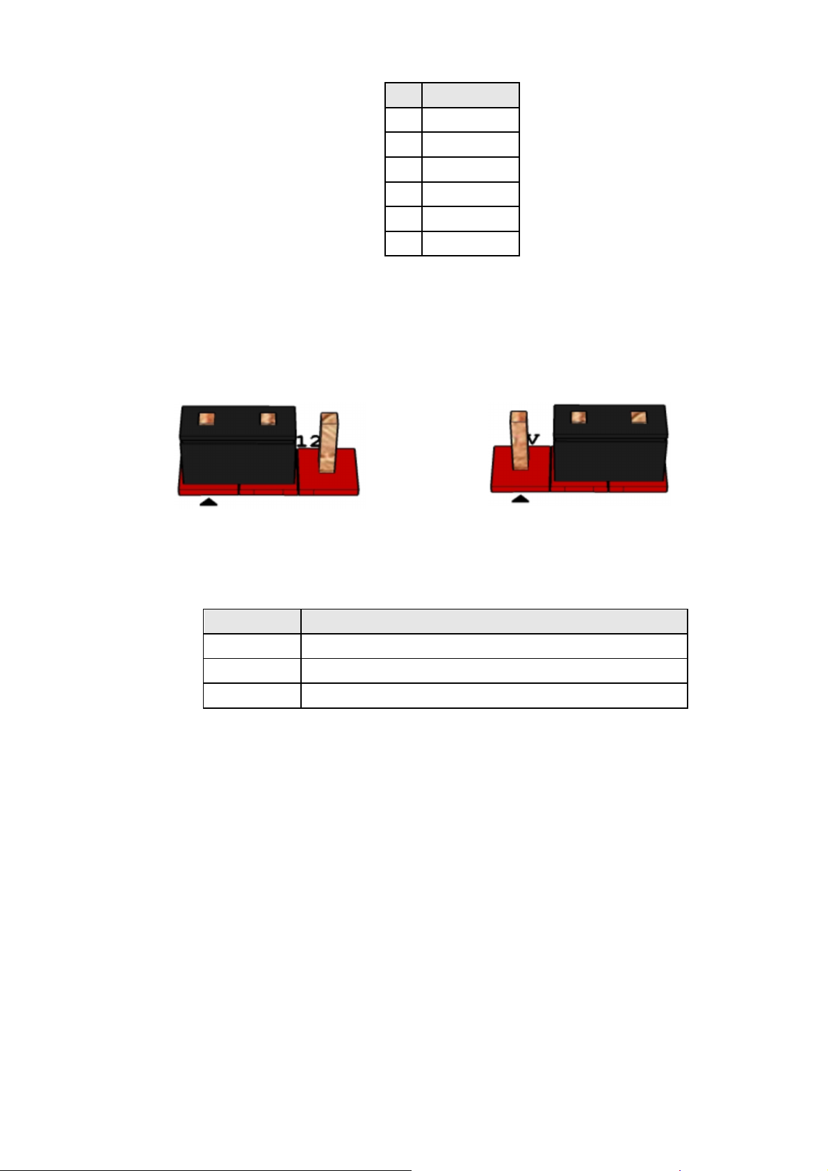
Pin Signal Name
1 NC
2 VCC3/3V
3 12V
4 LCD SEL PWR
5 NC
6 VCC/5V
T
AB L E
12: LVDS
P A N E L VOL T A GE SE L E CTIO N HEADE R
Inverter power voltage selection header
Pins 1&2: jumper position for 12V Pins 3&2: jumper position for 19V
Figu re 1 3 : I nver t e r po w er v olt a ge se l e c t i o n h e ad e r
Pin Signal Name
T
AB L E
1 12V
2 BKLT_PWR
3 12V
13: I
NV E R T ER P O WER V O L TAGE S E LECT I ON H E A DER
15
Page 16
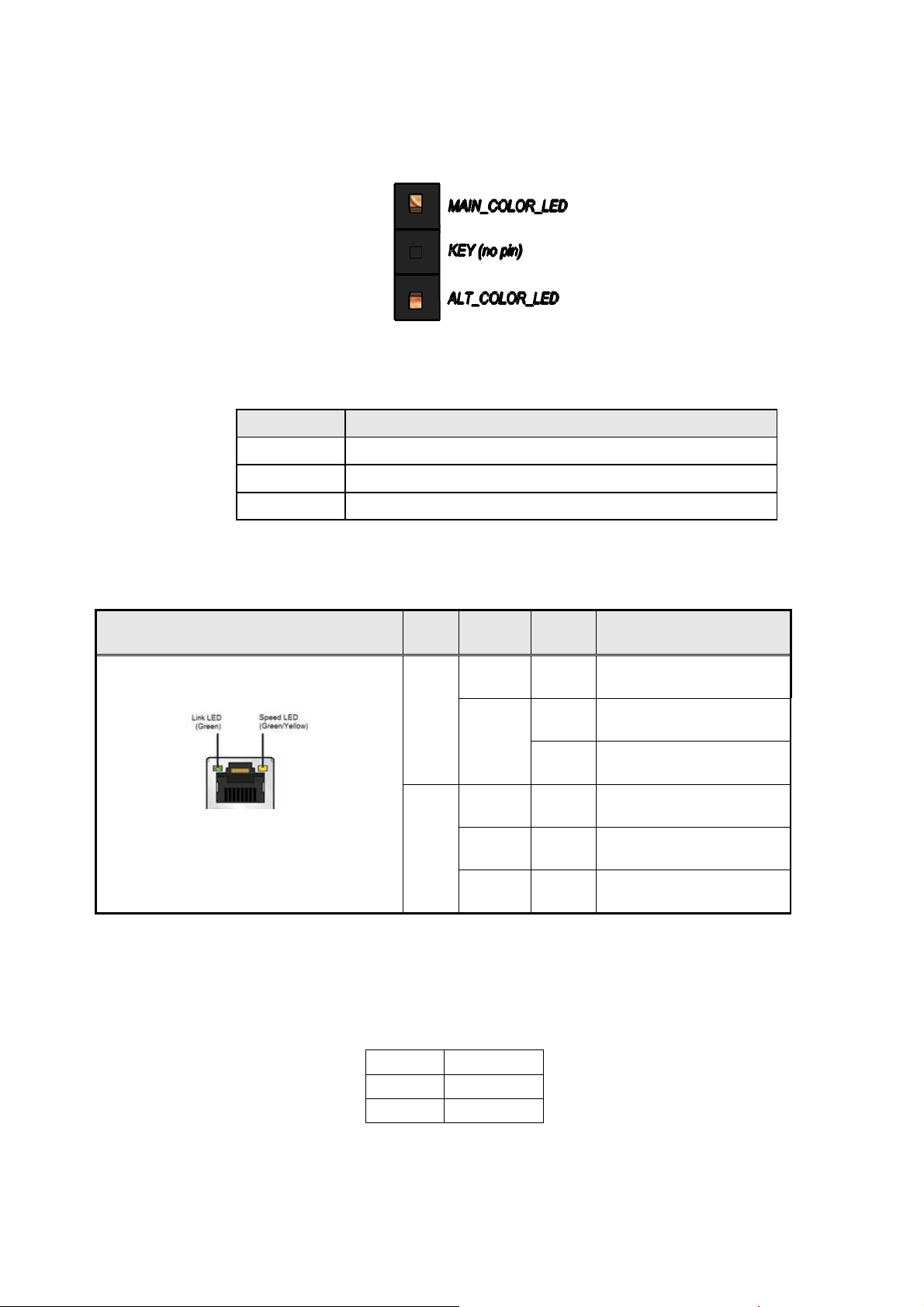
Alternate Power LED header
Figure 14 Alternate Power LED header
Pin Signal Name
1 MAIN COLOR LED
2 KEY
3 ALT COLOR LED
T
RJ45 LED behavior
Diagram LED Color State Condition
Note: LAN solution must be tested for IEEE802.3 conformance
AB L E
14: A
T
AB L E
LT E R N A TE POWE R
N/A Off LAN link is not established
Link
Green
N/A Off 10 Mb/s data rate
Speed
15: RJ45 LE D
Green On 100 Mb/s data rate
Yellow On 1000 Mb/s data rate
B E H A VIOR
LE D
H E A DER
On LAN link is established
Blinking LAN activity occurring
CMOS Clear
CMOS Clear
1-2 Normal
2-3 Clear CMOS
T
AB L E
18:
CM OS C
LE A R BEHAV I O R
16
Page 17

MITAC Desktop Board PH12LI
BIOS Specifiction
17
Page 18

18
Page 19
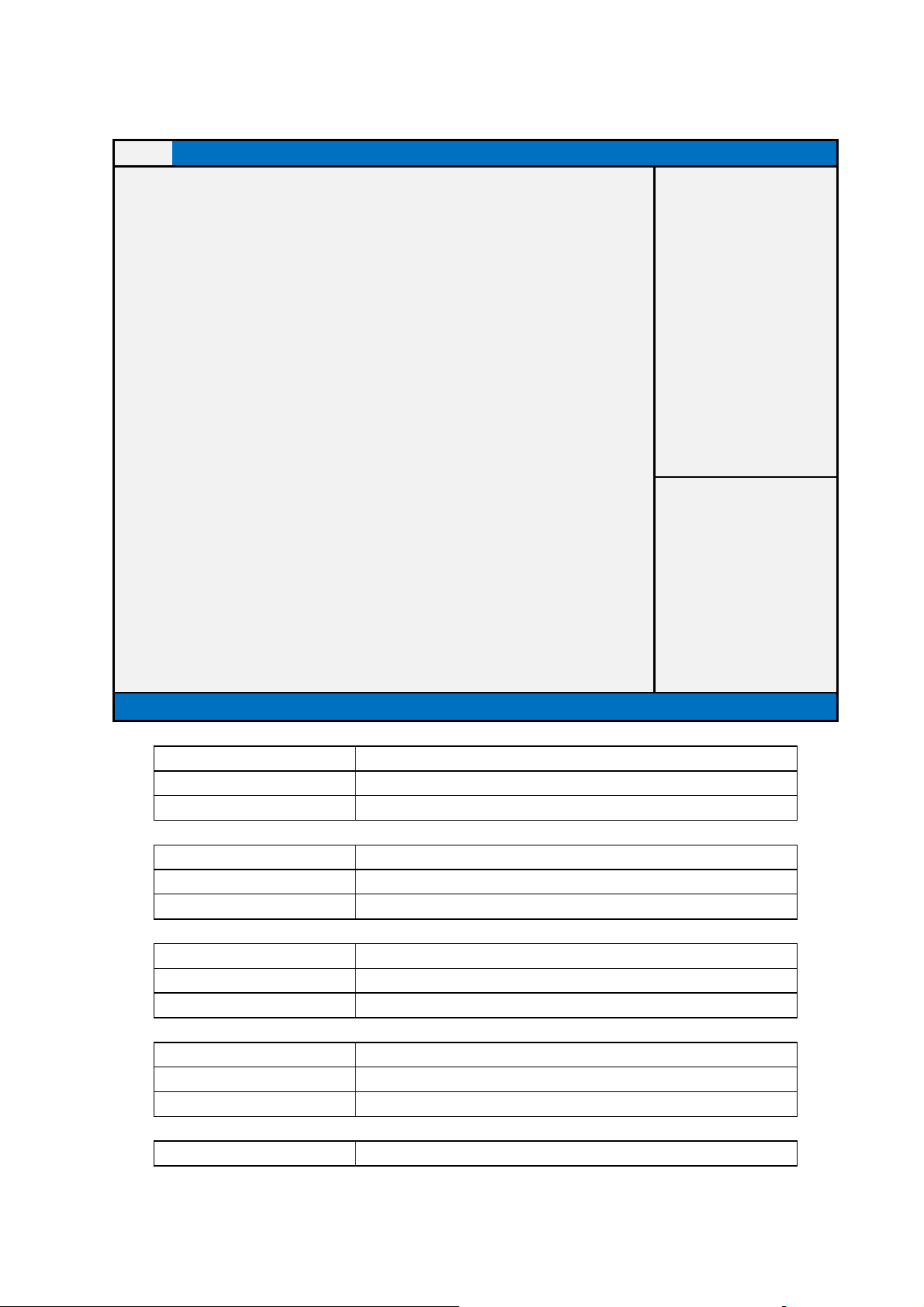
Date
This field is not selectable. There is no help text associated with it.
help text associated with it.
This field is not selectable. There is no help text associated with it.
field is not selectable. There is no help text associated with it.
1. Main Page
Main Advanced Chipset Boot Security Save & Exit
BIOS Information
BIOS Vender American Megatrends
Core Version 4.6.5.4
Compliancy UEFI 2.3.1; PI 1.2
BIOS Version D7340X01
Build Date and Time
11/07/2013 14:02:20
Processor Information
Intel(R) Core(TM) i5-3550S CPU @ 3.00GHz
Frequency 3000 MHz
Processor ID 306c3
Microcode Revision 16
Primary VBIOS Version 2177
Total Memory 16384 MB (DDR3)
Memory Frequency 1333 Mhz
ME FW Revision 9.0.20.1447
System
[Mon mm/dd/yyyy]
System Time [hh: mm:ss]
Version 2.15.1236. Copyright (C) 2012 American Megatrends, Inc.
Item help
→←: Select Screen
↑↓: Select Item
Enter: Select
+/- : Change Opt
F1: General Help
F2: Previous Values
F3: Optimized Defaults
F4: Save & Reset
ESC: Exit
Field Name
Default Value AMI Megatrends
Comment
BIOS Vender
Field Name
Default Value 4.6.5.4
Comment This field is not selectable. There is no
Core Version
Field Name
Default Value UEFI 2.3.1; PI 1.2
Comment
Complacency
Field Name
Default Value Display the version of the BIOS
Comment This
BIOS Version
Field Name
Build Date and Time
19
Page 20

This field is not selectable. There is no help text associated with it.
This field is not selectable. There is no help text associated with it.
text associated with it.
This field is not selectable. There is no help text associated with it.
field is not selectable. There is no help text associated with it.
This field is not selectable. There is no help text associated with it.
This field is not selectable. There is no help text associated with it.
with it.
This field is not selectable. There is no help text associated with it.
Default Value Display build date and time of the BIOS
Comment
Field Name
Value Display the installed CPU brand.
Comment
Processor Information
Field Name
Value Display processor frequency
Comment This field is not selectable. There is no help
Frequency
Field Name
Value Display processor ID.
Comment
Processor ID
Field Name Microcode Revision
Value Display processor micro-code revision.
Comment This
Field Name
Value Display Integrate VGA BIOS version.
Comment
Primary VBIOS Version
Field Name
Value Display the installed memory size.
Comment
Total Memory
Field Name
Value Display memory frequency.
Comment This field is not selectable. There is no help text associated
Memory Frequency
Field Name
Value Display ME F/W version.
Comment
ME FW Version
Field Name
Default Value [xxx, mm dd yyyy]
Possible Value [xxx, xx:xx:xxxx]
Help Set the Date. Use Tab to switch between Date elements.
System Date
Field Name
Default Value [hh :mm :ss]
Possible Value [xx :xx :xx]
System Time
20
Page 21

Help Set the Time. Use Tab to switch between Time elements.
21
Page 22
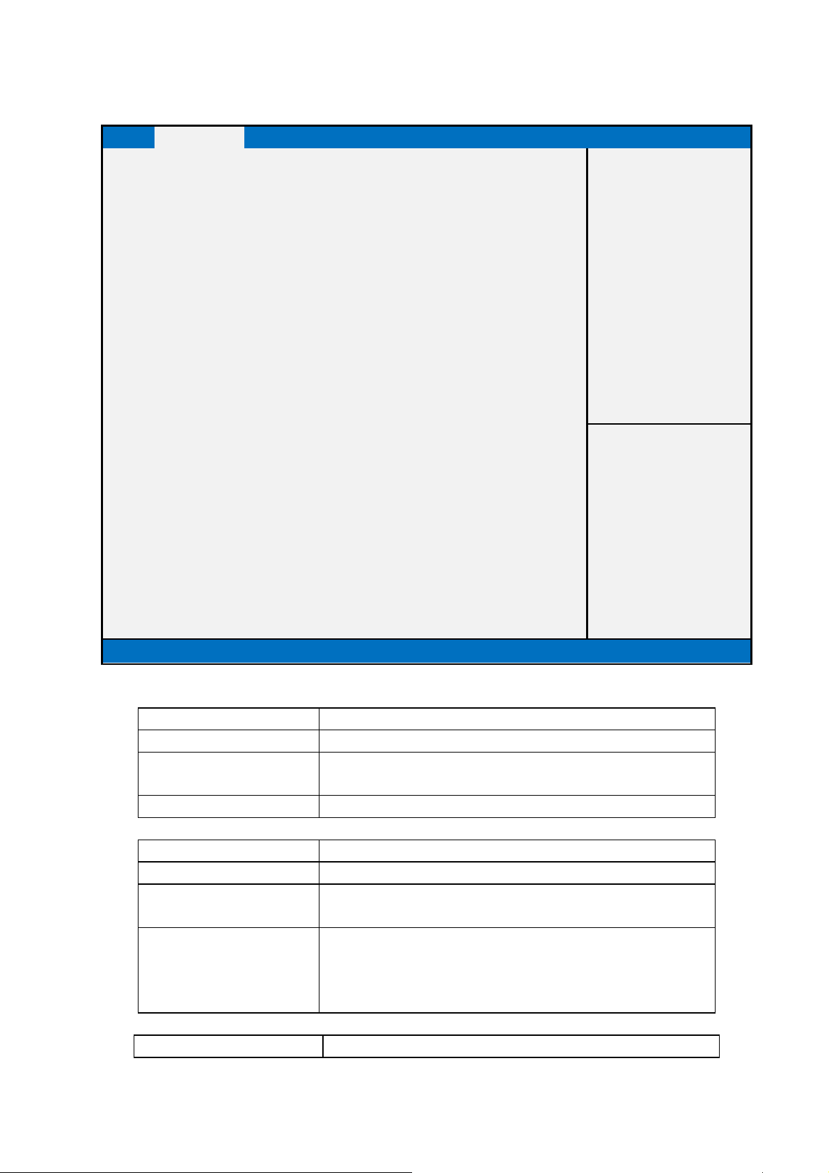
2. Advanced Page
Main Advanced Chipset Boot Security Save & Exit
Wireless RF
Quick Charging [Disabled]
►S5 RTC Wake Settings
►Trusted Computing
►CPU Configuration
►SATA Configuration
►Intel Rapid Start Technology
►AMT Configuration
►USB Configuration
►SMART Settings
►NCT6683D Super IO Configuration
►Network Stack
►Intel ® Ethernet Network Connection i217-LM – 88:88:88:…
►Intel ® I210 Gigabit Network Connection – 00:22:4D:A7:…
F4: Save & Reset
Version 2.15.1236. Copyright (C) 2012 American Megatrends, Inc.
Item help
→←: Select Screen
↑↓: Select Item
Enter: Select
+/- : Change Opt
F1: General Help
F2: Previous Values
F3: Optimized Defaults
ESC: Exit
Field Name Wireless RF
Default Value [Enabled]
Possible Value Enabled
Disabled
Help Enable or Disable Wireless RF switch.
Field Name
Default Value [Disabled]
Possible Value Enabled
Help Enable: This selection allow user enable quick charging support
Field Name
Quick Charging
Disabled
Under S0 – S5 but USB function disabled.
Disable: This selection disable quick charging function, treat this
Port as normal USB port.
S5 RTC Wake Settings
22
Page 23

Help Enable system to wake from S5 using RTC alarm
Comment Press Enter when selected to go into the associated Sub-Menu.
Field Name
Help Trusted Computing Settings
Comment Press Enter when selected to go into the associated Sub-Menu.
Field Name
Help CPU Configuration Parameters
Comment Press Enter when selected to go into the associated Sub-Menu.
Field Name
Help SATA Devices Options Settings.
Comment Press Enter when selected to go into the associated Sub-Menu.
Field Name Intel Rapid Start Technology
Help Intel(R) Rapid Start Technology.
Comment Press Enter when selected to go into the associated Sub-Menu.
Trusted Computing
CPU Configuration
SATA Configuration
Field Name
Help Configure Active Management Technology Parameters.
Comment Press Enter when selected to go into the associated Sub-Menu.
AMT Configuration
Field Name
Help USB Configuration Parameters.
Comment Press Enter when selected to go into the associated Sub-Menu.
USB Configuration
Field Name
Help System SMART Settings.
Comment Press Enter when selected to go into the associated Sub-Menu.
SMART Settings
Field Name
Help System Super IO Chip Parameters.
Comment Press Enter when selected to go into the associated Sub-Menu.
NCT6683D Super IO Configuration
Field Name
Help Network stack Settings.
Comment Press Enter when selected to go into the associated Sub-Menu.
Network Stack
Field Name
Help Configure Gigabit Ethernet device parameters.
Comment Press Enter when selected to go into the associated Sub-Menu.
Intel ® Ethernet Network Connection i217-LM –
88:88:88:87:88
23
Page 24

Field Name
Intel ® I210 Gigabit Network Connection –
00:22:4D:A7:23:9B
Help Configure Gigabit Ethernet device parameters.
Comment Press Enter when selected to go into the associated Sub-Menu.
24
Page 25
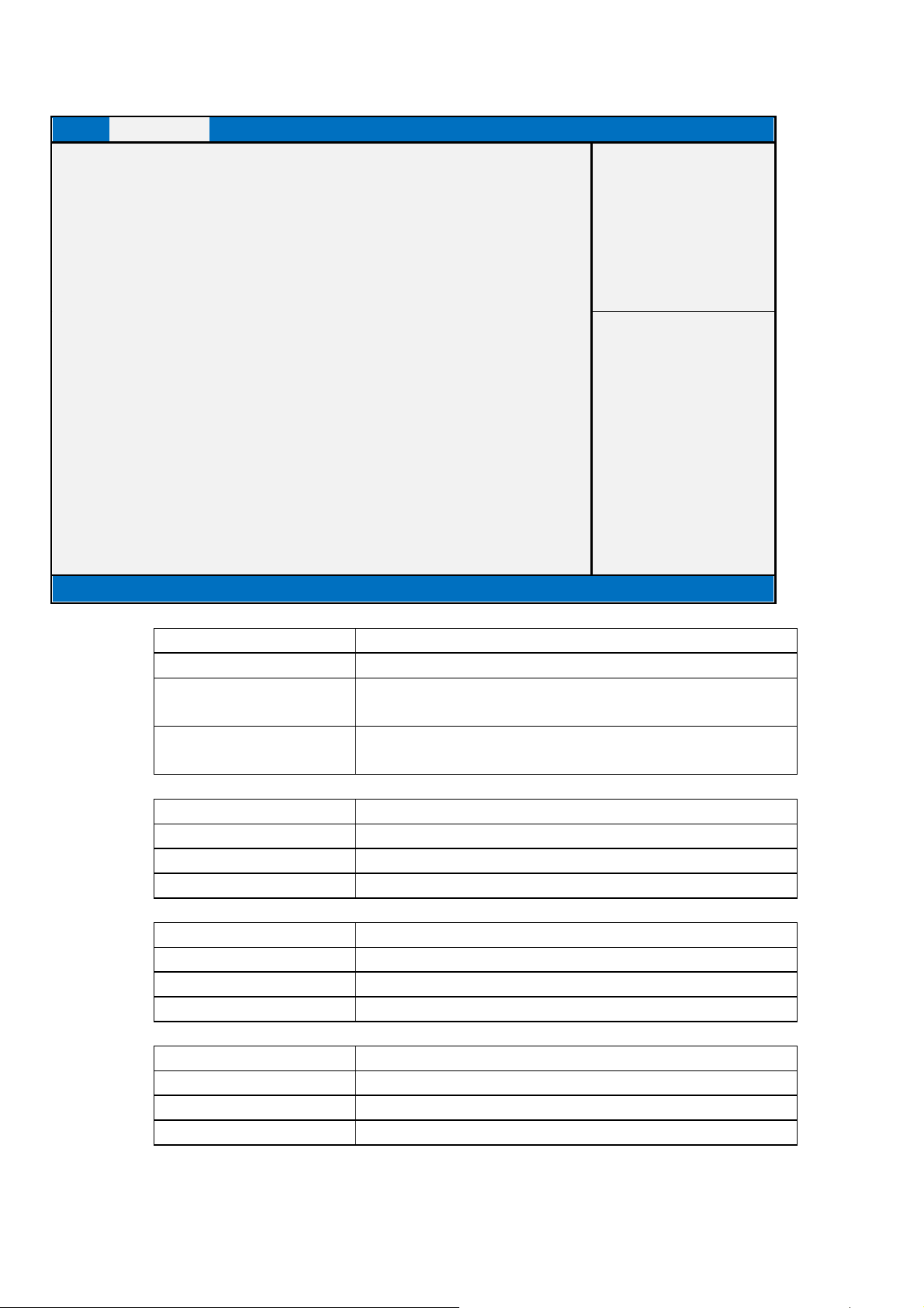
2.1 S5 RTC Wake Settings
Main Advanced Chipset Boot Security Save & Exit
Wake system with Fixed Time [Enabled]
Item help
Wake up hour 0
Wake up minute 0
Wake up second 0
Version 2.15.1326. Copyright (C) 2012 American Megatrends, Inc.
Field Name
Default Value [Disabled]
Possible Value Enabled
Help Enable or Disable System wake on alarm event. When enabled,
Field Name
Default Value [0]
Possible Value 0-23
Help Select 0-23 For example enter 3 for 3am and 15 for 3pm
Field Name
Default Value [0]
Possible Value 0-59
Help 0 - 59
Field Name
Default Value [0]
Possible Value 0 - 59
Help 0 - 59
Wake system with Fixed Time
Disabled
System will wake on the hr::min::sec specified
Wake up hour
Wake up minute
Wake up second
→←: Select Screen
↑↓: Select Item
Enter: Select
+/- : Change Opt
F1: General Help
F2: Previous Values
F3: Optimized Defaults
F4: Save & Reset
ESC: Exit
25
Page 26
not show Security Device. TCG EFI protocol and INT1A interface will
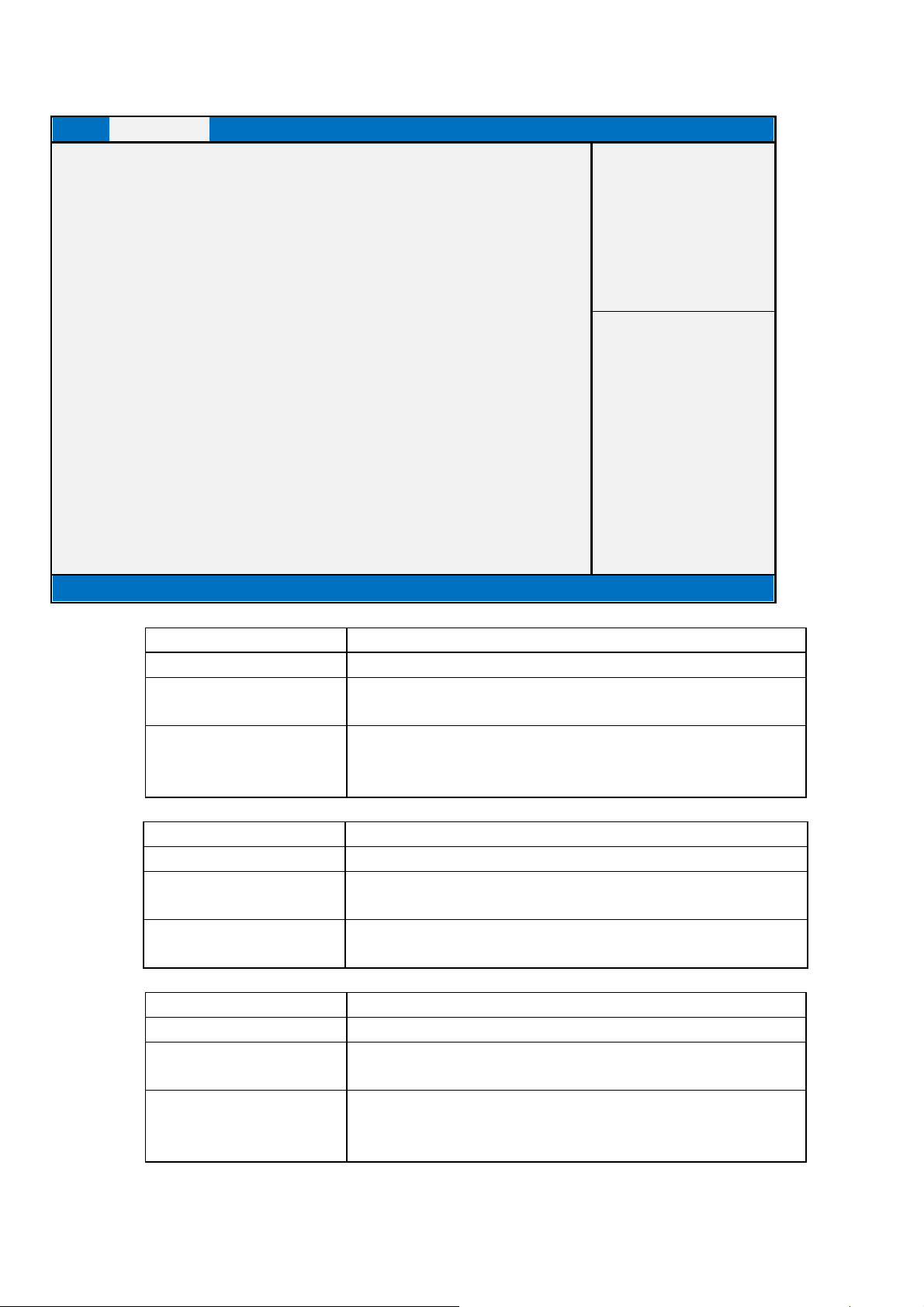
2.2 Trusted Computing
Main Advanced Chipset Boot Security Save & Exit
Configuration
Item help
Security Device Support [Enable]
TPM State [Enabled]
Pending operation [None]
Current Status Information
TPM Enabled Status: [Enabled]
TPM Active Status: [Activated]
TPM Owner Status: [Owned]
Version 2.15.1326. Copyright (C) 2012 American Megatrends, Inc.
Field Name
Default Value [Enable]
Possible Value Enable
Help Enables or Disables BIOS support for security device. O.S. will
Security Device Support
Disable
→←: Select Screen
↑↓: Select Item
Enter: Select
+/- : Change Opt
F1: General Help
F2: Previous Values
F3: Optimized Defaults
F4: Save & Reset
ESC: Exit
not be available.
Field Name
Default Value [Enabled]
Possible Value Enabled
Help Enable/Disable Security Device. NOTE: Your Computer will
Field Name Pending operation
Default Value [None]
Possible Value None / Enable Take Ownership / Disable Take Ownership /
Help Schedule an Operation for the Security Device. NOTE: Your
TPM State
Disabled
reboot during restart in order to change State of the Device.
TPM Clear
Computer will reboot during restart in order to change State of
Security Device.
26
Page 27

Field Name
Default Value [Enabled]
Comment This field is not selectable. There is no help text associated with it.
TPM Enabled Status:
Field Name
Default Value [Activated]
Comment This field is not selectable. There is no help text associated with it.
TPM Active Status:
Field Name
Default Value [Owned]
Comment This field is not selectable. There is no help text associated with it.
TPM Owner Status:
27
Page 28
2.3 CPU Configuration
Main Advanced Chipset Boot Security Save & Exit
CPU Configuration
Item help
Intel(R) Core(TM) CPU [CPU NAME] @ [CPU Freq.] GHz
CPU Signature 306c3
Microcode Patch 16
Max CPU Speed 3400 MHz
Min CPU Speed 800 MHz
CPU Speed 3400 MHz
Processor Cores 4
Intel HT Technology Supported
Intel VT-x Technology Supported
Intel SMX Technology Supported
64-bit Supported
L1 Data Cache 32 KB x 4
L1 Code Cache 32 KB x 4
L2 Cache 256 KB x 4
L3 Cache 6144 KB
Hyper-threading [Enabled]
Active Processor Cores [All]
Intel Virtualization Technology [Enabled]
EIST [Enabled]
Turbo Mode [Enabled]
CPU C3 Report [Enabled]
CPU C6 Report
CPU C7 Report
[Enabled]
[CPU C7s]
Intel TXT(LT) Support [Disabled]
Version 2.15.1326. Copyright (C) 2012 American Megatrends, Inc.
→←: Select Screen
↑↓: Select Item
Enter: Select
+/- : Change Opt
F1: General Help
F2: Previous Values
F3: Optimized Defaults
F4: Save & Reset
ESC: Exit
Field Name
Default Value [Intel CPU Brand String]
Comment This field is not selectable. There is no help text associated with it.
Field Name
Default Value Displays CPU Signature
Comment This field is not selectable. There is no help text associated with it.
CPU Configuration
CPU Signature
28
Page 29

Field Name
Default Value CPU Microcode Patch Revision
Comment This field is not selectable. There is no help text associated with it.
Microcode Patch
Field Name
Default Value Displays the Max CPU Speed
Comment This field is not selectable. There is no help text associated with it.
Max CPU Speed
Field Name
Default Value Displays the Min CPU Speed
Comment This field is not selectable. There is no help text associated with it.
Min CPU Speed
Field Name
Default Value Displays the CPU Speed
Comment This field is not selectable. There is no help text associated with it.
CPU Speed
Field Name
Default Value Displays number of cores.
Comment This field is not selectable. There is no help text associated with it.
Processor Cores
Field Name
Default Value When Hyper-threading is enabled, 2 logical CPUS per core is
Comment This field is not selectable. There is no help text associated with it.
Intel HT Technology
present.
Field Name
Default Value CPU VMX hardware support for virtual machines.
Comment This field is not selectable. There is no help text associated with it.
Intel VT-x Technology
Field Name
Default Value Secure Mode extensions support.
Comment This field is not selectable. There is no help text associated with it.
Intel SMX Technology
Field Name
Default Value Displays if 64-bit supported
Comment This field is not selectable. There is no help text associated with it.
64-bit
Field Name
Default Value L1 Data Cache Size
Comment This field is not selectable. There is no help text associated with it.
L1 Data Cache
Field Name
Default Value L1 Code Cache Size
Comment This field is not selectable. There is no help text associated with it.
L1 Code Cache
29
Page 30
Field Name
Default Value L2 Cache Size
Comment This field is not selectable. There is no help text associated with it.
L2 Cache
Field Name
Default Value L3 Cache Size
Comment This field is not selectable. There is no help text associated with it.
L3 Cache
Field Name
Default Value [Enabled]
Possible Value Enabled
Help Enabled for Windows XP and Linux (OS optimized for
Hyper-threading (Hided if HT Not Supported)
Disabled
Hyper-Threading Technology) and Disabled for other OS (OS not
optimized for Hyper-Threading Technology). When Disable only
one thread per enabled core is enabled.
Field Name
Default Value [All]
Possible Value All
Help Number of cores to enable in each processor package.
Active Processor Cores
1/2/3/4/5/6/7/8
Field Name
Default Value [Enabled]
Possible Value Enabled
Help When enabled, a VMM can utilize the additional hardware
Intel Virtualization Technology
Disabled
capabilities provided by Vanderpool Technology
Field Name
Default Value [Enabled]
Possible Value Disabled
Help Enable/Disable Intel SpeedStep.
EIST
Enabled
Field Name
Default Value [Enabled]
Possible Value Disabled
Help Turbo Mode.
Turbo Mode
Enabled
Field Name
CPU C3 Report
30
Page 31

Default Value [Enabled]
Possible Value Disabled
Enabled
Help Enable/Disable CPU C3 report to OS
Field Name
Default Value [Enabled]
Possible Value Disabled
Help Enable/Disable CPU C6 report to OS
CPU C6 Report
Enabled
Field Name
Default Value [CPU C7s]
Possible Value Disabled / CPU C7 / CPU C7s
Help Enable/Disable CPU C7 report to OS
CPU C7 Report
Field Name
Default Value [Disabled]
Possible Value Disabled
Help Enables or Disables Intel ® TXT(LT) support.
Intel TXT(LT) Support
Enabled
31
Page 32
2.4 SATA Configuration
Main Advanced Chipset Boot Security Save & Exit
Item help
SATA Mode Selection [AHCI]
SATA Controller Speed [Default]
Serial ATA Port 0
Port 0
Hot Plug
mSATA Port
mSATA Port
Serial ATA Port 2
Port 2
Hot Plug
Serial ATA Port 3
Port 3
Hot Plug
Empty
[Enabled]
[Disabled]
Empty
[Enabled]
Empty
[Enabled]
[Disabled]
Empty
[Enabled]
[Disabled]
Serial ATA Port 4 Empty
Port 4 [Enabled]
Hot Plug [Disabled]
Version 2.15.1326. Copyright (C) 2012 American Megatrends, Inc.
→←: Select Screen
↑↓: Select Item
Enter: Select
+/- : Change Opt
F1: General Help
F2: Previous Values
F3: Optimized Defaults
F4: Save & Reset
ESC: Exit
Field Name
Default Value [AHCI]
Possible Value IDE / AHCI /RAID
Help Determines how SATA controller(s) operate.
Field Name
Default Value [Default]
Possible Value Default / Gen1 / Gen2 / Gen3
Help Indicates the maximum speed the SATA controller can support.
Field Name
Default Value Empty
Possible Value SATA Device Model Name
Field Name
SATA Mode Selection
SATA Controller Speed
Serial ATA Port 0
Port 0
32
Page 33

Default Value [Enabled]
Possible Value Disabled / Enabled
Help Enable or Disable SATA Port.
Field Name
Default Value [Disabled]
Possible Value Disabled / Enabled
Help Designates this port as Hot Pluggable.
Hot Plug
Field Name
Default Value Empty
Possible Value SATA Device Model Name
mSATA Port
Field Name
Default Value [Enabled]
Possible Value Disabled / Enabled
Help Enable or Disable SATA Port.
mSATA Port
Field Name
Default Value Empty
Possible Value SATA Device Model Name
Serial ATA Port 2
Field Name
Default Value [Enabled]
Possible Value Disabled / Enabled
Help Enable or Disable SATA Port.
Port 2
Field Name
Default Value [Disabled]
Possible Value Disabled / Enabled
Help Designates this port as Hot Pluggable.
Hot Plug
Field Name
Default Value Empty
Possible Value SATA Device Model Name
Serial ATA Port 3
Field Name
Default Value [Enabled]
Possible Value Disabled / Enabled
Help Enable or Disable SATA Port.
Port 3
Field Name
Default Value [Disabled]
Hot Plug
33
Page 34

Possible Value Disabled / Enabled
Help Designates this port as Hot Pluggable.
Field Name
Default Value Empty
Possible Value SATA Device Model Name
Serial ATA Port 4
Field Name
Default Value [Enabled]
Possible Value Disabled / Enabled
Help Enable or Disable SATA Port.
Port 4
Field Name
Default Value [Disabled]
Possible Value Disabled / Enabled
Help Designates this port as Hot Pluggable.
Hot Plug
34
Page 35
2.5 Intel® Rapid Start Technology
Main Advanced Chipset Boot Security Save & Exit
Intel(R) Rapid Start Technology [Enabled]
No valid partition.
Entry on S3 RTC Wake [Enabled]
Entry After 10
Active Page Threshold Support [Disabled]
Version 2.15.1326. Copyright (C) 2012 American Megatrends, Inc.
Item help
→←: Select Screen
↑↓: Select Item
Enter: Select
+/- : Change Opt
F1: General Help
F2: Previous Values
F3: Optimized Defaults
F4: Save & Reset
ESC: Exit
Field Name
Default Value [Disabled]
Possible Value Disabled
Help Enable or disable Intel(R) Rapid Start Technology.
Field Name
Default Value [Enabled]
Possible Value Disabled
Help RapidStart invocation upon S3 RTC wake.
Field Name
Default Value 10
Possible Value 0 - 120
Help Enable RTC wake timer at S3 entry. Value range from
Field Name
Default Value [Disabled]
Possible Value Disabled
Help Support RST with small partition.
Intel(R) Rapid Start Technology
Enabled
Entry on S3 RTC Wake
Enabled
Entry After
0(Immediately) to 120 minutes.
Active Page Threshold Support
Enabled
35
Page 36

2.6 AMT Configuration
Main Advanced Chipset Boot Security Save & Exit
Intel AMT [Enabled]
BIOS Hotkey Pressed [Disabled]
MEBx Selection Screen [Disabled]
Hide Un-Configure ME Confirmation
MEBx Debug Message Output
Un-Configure ME
Amt Wait Timer
Disable ME
[Disabled]
[Disabled]
[Disabled]
0
[Disabled]
ASF [Enabled]
Activate Remote Assistance Process [Disabled]
USB Configure [Enabled]
PET Progress [Enabled]
AMT CIRA Timeout 0
WatchDog [Disabled]
OS Timer 0
BIOS Timer 0
Version 2.15.1326. Copyright (C) 2012 American Megatrends, Inc.
Item help
→←: Select Screen
↑↓: Select Item
Enter: Select
+/- : Change Opt
F1: General Help
F2: Previous Values
F3: Optimized Defaults
F4: Save & Reset
ESC: Exit
Field Name
Default Value [Enabled]
Possible Value Disabled / Enabled
Help Enable/Disable Intel(R) Active Management Technology BIOS
Field Name
Default Value [Disabled]
Possible Value Disabled / Enabled
Help OEMFlag Bit 1: Enable/Disable BIOS hotkey press.
Field Name
Default Value [Disabled]
Possible Value Disabled / Enabled
Help OEMFlag Bit 2: Enable/Disable MEBx selection screen.
Field Name
Default Value [Disabled]
Intel AMT
Extension.
Note: iAMT H/W is always enabled. This option just controls the
BIOS extension execution. If enabled, this requires additional
firmware in the SPI device.
BIOS Hotkey Pressed
MEBx Selection Screen
Hide un-Configure ME Confirmation
36
Page 37

Possible Value Disabled / Enabled
Help OEMFlag Bit 6: Hide un-configure ME without password
confirmation prompt.
Field Name
Default Value [Disabled]
Possible Value Disabled / Enabled
Help OEMFlag Bit 14: Enable MEBx debug message output.
ME Debug Message Output
Field Name
Default Value [Disabled]
Possible Value Disabled / Enabled
Help OEMFlag Bit 15: Un-Configure ME without password.
Un-Configure ME
Field Name
Default Value 0
Possible Value 0 - 65535
Help Set timer to wait before sending ASF_GET_BOOT_OPTIONS..
Amt Wait Timer
Field Name
Default Value Disabled
Possible Value Disabled / Enabled
Help Set ME to Soft Temporary Disabled.
Disable ME
Field Name
Default Value Enabled
Possible Value Disabled / Enabled
Help Enable/Disable Alert Specification Format.
ASF
Field Name
Default Value Disabled
Possible Value Disabled / Enabled
Help Trigger CIRA boot
Activate Remote Assistance Process
Field Name
Default Value Enabled
Possible Value Disabled / Enabled
Help Enable/Disabled USB Configure function.
USB Configure
Field Name
Default Value Enabled
Possible Value Disabled / Enabled
Help User can Enable/Disabled PET events progress to receive PET
PET Progress
events or not.
37
Page 38

Field Name
Default Value 0
Possible Value 0 - 255
Help OEM defined timeout for MPS connection to be established.
AMT CIRA Timeout
0 – use the default timeout value of 60 seconds.
255 – MEBX waits until the connection succeeds.
Field Name
Default Value Disabled
Possible Value Disabled / Enabled
Help Enable/Disable Watchdog Timer.
WatchDog
Field Name
Default Value 0
Possible Value 0 – 65535
Help Set OS watchdog timer.
OS Timer
Field Name
Default Value 0
Possible Value 0 – 65535
Help Set BIOS watchdog timer.
BIOS Timer
38
Page 39
This field is not selectable. There is no help text associated with it.
2.7 USB Configuration
Main Advanced Chipset Boot Security Save & Exit
USB Configuration
Item help
USB Devices:
1 Keyboard, 1 Mouse, 2 Hubs
Legacy USB Support [Enabled]
XHCI Hand-off [Enabled]
EHCI Hand-off [Disabled]
Version 2.15.1326. Copyright (C) 2012 American Megatrends, Inc.
Field Name
Default Value Connected USB devices
Comment
Field Name
Default Value [Enabled]
Possible Value Disabled
Help Enables Legacy USB support. AUTO option disables legacy
Field Name
Default Value [Enabled]
Possible Value Disabled
Help This is a workaround for OSes without XHCI hand-off support.
Field Name
Default Value [Disabled]
Possible Value Disabled
USB Devices:
Legacy USB Support
Enabled
Auto
support if no USB devices are connected. DISABLE option will
keep USB devices available only for EFI applications.
XHCI Hand-off
Enabled
The XHCI ownership change should be claimed by XHCI driver.
EHCI Hand-off
→←: Select Screen
↑↓: Select Item
Enter: Select
+/- : Change Opt
F1: General Help
F2: Previous Values
F3: Optimized Defaults
F4: Save & Reset
ESC: Exit
39
Page 40

Enabled
Help This is a workaround for OSes without EHCI hand-off support.
The EHCI ownership change should be claimed by EHCI driver.
40
Page 41
2.8 SMART Settings
Main Advanced Chipset Boot Security Save & Exit
SMART Settings
SMART Self Test [Disabled]
Version 2.15.1326. Copyright (C) 2012 American Megatrends, Inc.
Item help
→←: Select Screen
↑↓: Select Item
Enter: Select
+/- : Change Opt
F1: General Help
F2: Previous Values
F3: Optimized Defaults
F4: Save & Reset
ESC: Exit
Field Name
Default Value [Disabled]
Possible Value Disabled
Help Run SMART Self Test on all HDDs during POST.
SMART Self Test
Enabled
41
Page 42
2.9 NCT6683D Super IO Configuration
Main Advanced Chipset Boot Security Save & Exit
NCT6683D Super IO Configuration
Serial Port 0 [Enabled]
Serial Port 1 [Enabled]
Version 2.15.1326. Copyright (C) 2012 American Megatrends, Inc.
Item help
→←: Select Screen
↑↓: Select Item
Enter: Select
+/- : Change Opt
F1: General Help
F2: Previous Values
F3: Optimized Defaults
F4: Save & Reset
ESC: Exit
Field Name
Default Value [Enabled]
Possible Value Disabled
Help Enable or Disable Serial Port (COM).
Field Name
Default Value [Enabled]
Possible Value Disabled
Help Enable or Disable Serial Port (COM).
Serial Port 0
Enabled
Serial Port 1
Enabled
42
Page 43
Ipv4 PXE Boot Support. If disabled IPV4 PXE boot option
PXE Boot Support. If disabled IPV4 PXE boot option
2.10 Network Stack
Main Advanced Chipset Boot Security Save & Exit
Item help
Network stack [Enabled]
Ipv4 PXE Support [Enabled]
Ipv6 PXE Support [Enabled]
Version 2.15.1326. Copyright (C) 2012 American Megatrends, Inc.
Field Name
Default Value [Enabled]
Possible Value Disabled
Help Enable/Disable UEFI network stack.
Field Name
Default Value [Enabled]
Possible Value Disabled
Help Enable
Field Name
Default Value [Enabled]
Possible Value Disabled
Help Enable Ipv6
Network stack
Enabled
Ipv4 PXE Support
Enabled
will not be created.
Ipv6 PXE Support
Enabled
will not be created.
→←: Select Screen
↑↓: Select Item
Enter: Select
+/- : Change Opt
F1: General Help
F2: Previous Values
F3: Optimized Defaults
F4: Save & Reset
ESC: Exit
43
Page 44
This field is not selectable. There is no help text associated with it.
This field is not selectable. There is no help text associated with it.
This field is not selectable. There is no help text associated with it.
help text associated with it.
2.11 Intel ® Ethernet Network Connection i217-LM - 88:88:88:88:87:88
Main Advanced Chipset Boot Security Save & Exit
PORT CONFIGURATION MENU
Item help
►NIC Configuration
Blink LEDs (range 0 -15 seconds) 0
PORT CONFIGURATION INFORMATION
UEFI Driver: Intel ® 1GbE DEV 5.1.00
Adapter PBA: FFFFFF-0FF
Chip Type Intel PCH LPT
PCI Device ID 153A
PCI Bus:Device:Function: 0:25:0
Link Status: [Disconnected]
Factory MAC Address: 88:88:88:88:87:88
Version 2.15.1326. Copyright (C) 2012 American Megatrends, Inc.
Field Name
Help Click to configure the network device port.
Comment Press Enter when selected to go into the associated Sub-Menu.
Field Name
Default Value 0
Possible Value 0 - 15
Help Blink LEDs for the specified duration (up to 15 seconds).
Field Name
Default Value Installed UEFI Driver Name
Comment
Field Name
Default Value Adapter PBA number
Comment
Field Name
Default Value Chip Type Name
Comment
Field Name
Default Value I217 PCI Device ID number
Comment This field is not selectable. There is no
NIC Configuration
Blink LEDs
UEFI Driver:
Adapter PBA:
Chip Type:
PCI Device ID:
→←: Select Screen
↑↓: Select Item
Enter: Select
+/- : Change Opt
F1: General Help
F2: Previous Values
F3: Optimized Defaults
F4: Save & Reset
ESC: Exit
44
Page 45

This field is not selectable. There is no help text associated with it.
This field is not selectable. There is no help text associated with it.
Field Name
Default Value [Bus:Device:Function]
Comment
PCI Bus:Device:Function:
Field Name
Default Value [Disconnected]
Help Link Status
Link Status
Field Name
Default Value LAN Device MAC address
Comment
Factory MAC Address:
45
Page 46
2.11.1 NIC Configuration
Main Advanced Chipset Boot Security Save & Exit
Item help
Link Speed [AutoNeg]
Wake on LAN [Enabled]
Version 2.15.1326. Copyright (C) 2012 American Megatrends, Inc.
Field Name
Default Value [AutoNeg]
Possible Value AutoNeg / 10 Mbps Half / 10 Mbps Full / 100 Mbps Half /
Help Change link speed and duplex for current port.
Field Name
Default Value [Enabled]
Possible Value Disabled / Enabled
Help Enable this option to wake the system with a magic packet.
Link Speed
100 Mbps Full
Wake on LAN
→←: Select Screen
↑↓: Select Item
Enter: Select
+/- : Change Opt
F1: General Help
F2: Previous Values
F3: Optimized Defaults
F4: Save & Reset
ESC: Exit
46
Page 47
with it.
This field is not selectable. There is no help text associated with it.
help text associated with it.
This field is not selectable. There is no help text associated with it.
2.12 Intel ® I210 Gigabit Network Connection - 00:22:4D:A7:23:9B
Main Advanced Chipset Boot Security Save & Exit
PORT CONFIGURATION MENU
Item help
►NIC Configuration
Blink LEDs (range 0-15 seconds) 0
PORT CONFIGURATION INFORMATION
UEFI Driver: Intel ® 1GbE DEV 5.1.00
Adapter PBA: 000500-000
Chip Type Intel i210
PCI Device ID 1533
PCI Bus:Device:Function 2:0:0
Link Status: [Disconnected]
Factory MAC Address: 00:22:4D:A7:23:B7
Alternate MAC Address 00:22:4D:A7:23:B7
Version 2.15.1326. Copyright (C) 2012 American Megatrends, Inc.
Field Name
Help Click to configure the network device port.
Comment Press Enter when selected to go into the associated Sub-Menu.
Field Name
Default Value 0
Possible Value 0 - 15
Help Blink LEDs for the specified duration (up to 15 seconds).
Field Name
Default Value Installed UEFI Driver Name
Comment This field is not selectable. There is no help text associated
Field Name
Default Value Adapter PBA number
Comment
Field Name
Default Value Chip Type Name
Comment This field is not selectable. There is no
Field Name
Default Value I217 PCI Device ID number
Comment
NIC Configuration
Blink LEDs
UEFI Driver:
Adapter PBA:
Chip Type:
PCI Device ID:
→←: Select Screen
↑↓: Select Item
Enter: Select
+/- : Change Opt
F1: General Help
F2: Previous Values
F3: Optimized Defaults
F4: Save & Reset
ESC: Exit
47
Page 48

This field is not selectable. There is no help text associated with it.
selectable. There is no help text associated with it.
Field Name
Default Value [Bus:Device:Function]
Comment
PCI Bus:Device:Function:
Field Name
Default Value [Disconnected]
Help Link Status
Link Status
Field Name
Default Value LAN Device MAC address
Comment This field is not
Factory MAC Address:
Field Name
Default Value LAN Device MAC address
Help Alternate assigned MAC address of Ethernet port.
Alternate MAC Address:
48
Page 49
2.12.1 NIC Configuration
Main Advanced Chipset Boot Security Save & Exit
Item help
Link Speed [AutoNeg]
Wake on LAN [Enabled]
Version 2.15.1326. Copyright (C) 2012 American Megatrends, Inc.
Field Name
Default Value [AutoNeg]
Possible Value AutoNeg / 10 Mbps Half / 10 Mbps Full / 100 Mbps Half /
Help Change link speed and duplex for current port.
Field Name
Default Value [Enabled]
Possible Value Disabled / Enabled
Help Enable this option to wake the system with a magic packet.
Link Speed
100 Mbps Full
Wake on LAN
→←: Select Screen
↑↓: Select Item
Enter: Select
+/- : Change Opt
F1: General Help
F2: Previous Values
F3: Optimized Defaults
F4: Save & Reset
ESC: Exit
49
Page 50
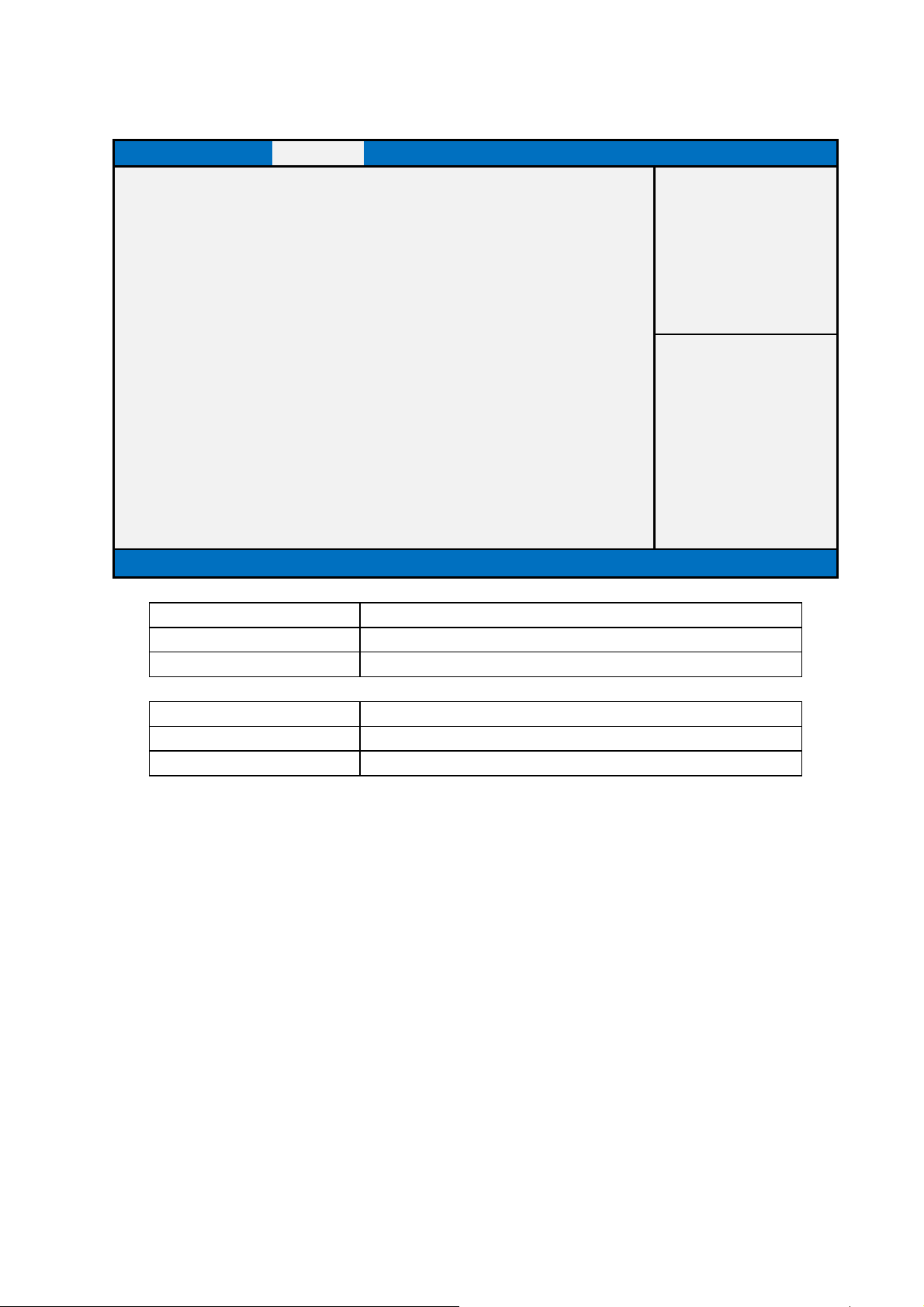
3. Chipset
Main Advanced Chipset Boot Security Save & Exit
►PCH-IO Configuration
►System Agent (SA) Configuration
Version 2.15.1326. Copyright (C) 2012 American Megatrends, Inc.
Item help
→←: Select Screen
↑↓: Select Item
Enter: Select
+/- : Change Opt
F1: General Help
F2: Previous Values
F3: Optimized Defaults
F4: Save & Reset
ESC: Exit
Field Name
Help PCH Parameters
Comment Press Enter when selected to go into the associated Sub-Menu.
Field Name
Help System Agent (SA) Parameters
Comment Press Enter when selected to go into the associated Sub-Menu.
PCH-IO Configuration
System Agent (SA) Configuration
50
Page 51
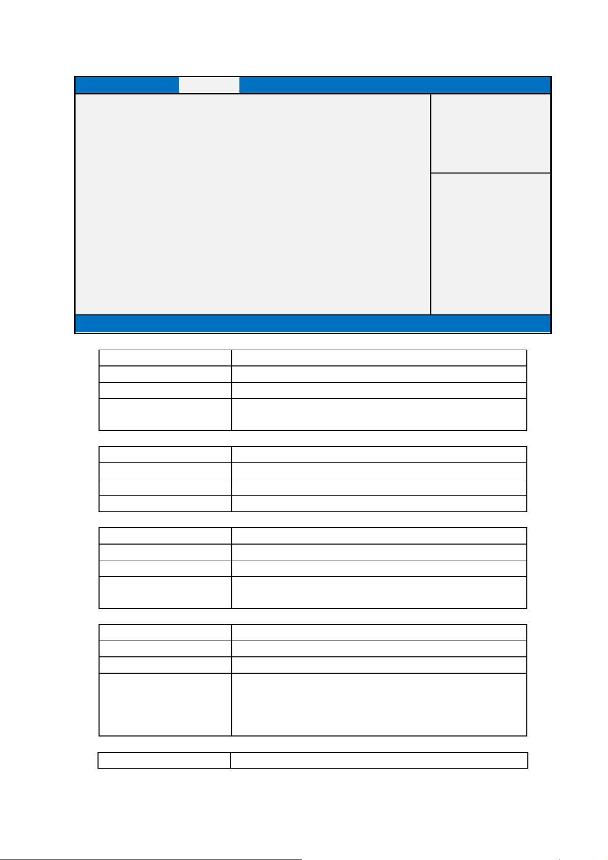
3.1 PCH-IO Configuration
Main Advanced Chipset Boot Security Save & Exit
Item help
Wake on LAN [Enabled]
DeepSx Power Policies [Disable]
Restore AC Power Loss [Power Off]
Onboard Audio [Auto]
Front Panel Audio [Auto]
Version 2.15.1326. Copyright (C) 2012 American Megatrends, Inc.
Field Name
Default Value [Enabled]
Possible Value Enabled / Disabled
Help Enable or disable integrated LAN to wake the system at S3,
Field Name
Default Value [Disabled]
Possible Value Disabled / Enabled in S5 / Enabled in S4-S5
Help Configure the DeepSx Mode configuration.
Field Name
Default Value [Power Off]
Possible Value Power Off / Power On / Last State
Help Select AC power state when power is re-applied after a power
Field Name
Default Value [Auto]
Possible Value Disable / Enabled / Auto
Help Control Detection of the Azalia device.
Field Name
Wake on LAN
S4 and S5 state.
DeepSx Power Policies
Restore AC Power Loss
failure.
Onboard Audio
Disabled = Azalia will be unconditionally disabled
Enabled = Azalia will be unconditionally enabled
Auto = Azalia will be enabled if present, disabled otherwise.
Front Panel Audio
→←: Select Screen
↑↓: Select Item
Enter: Select
+/- : Change Opt
F1: General Help
F2: Previous Values
F3: Optimized Defaults
F4: Save & Reset
ESC: Exit
51
Page 52

Default Value [Auto]
Possible Value Auto / High Definition Front Panel / Legacy Front Panel / Disabled
Help Automatically or Manually select the type of audio front panel
installed.
52
Page 53
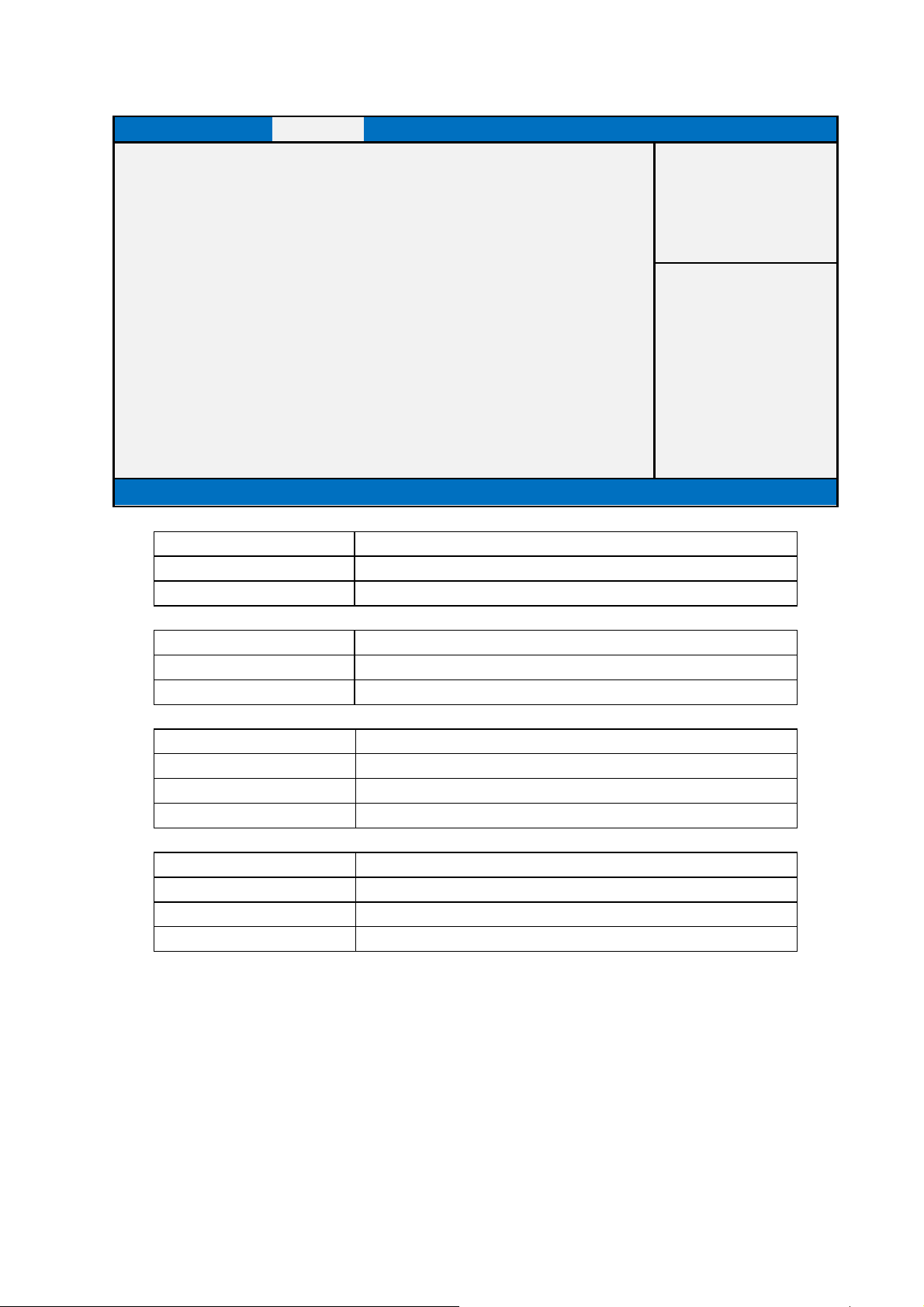
3.2 System Agent (SA) Configuration
Main Advanced Chipset Boot Security Save & Exit
Item help
►Graphics Configuration
►Memory Configuration
VT-d [Enabled]
CPU SA Audio Device [Enabled]
Version 2.15.1326. Copyright (C) 2012 American Megatrends, Inc.
Field Name
Help Config Graphics Settings.
Comment Press Enter when selected to go into the associated Sub-Menu.
Field Name
Help Memory Configuration Parameters
Comment Press Enter when selected to go into the associated Sub-Menu.
Field Name
Default Value [Enabled]
Possible Value Disable / Enabled
Help Check to enable VT-d function on MCH.
Field Name
Default Value [Enabled]
Possible Value Disable / Enabled
Help Enable or disable CPU SA Audio Device.
Graphics Configuration
Memory Configuration
VT-d
CPU SA Audio Device
→←: Select Screen
↑↓: Select Item
Enter: Select
+/- : Change Opt
F1: General Help
F2: Previous Values
F3: Optimized Defaults
F4: Save & Reset
ESC: Exit
53
Page 54
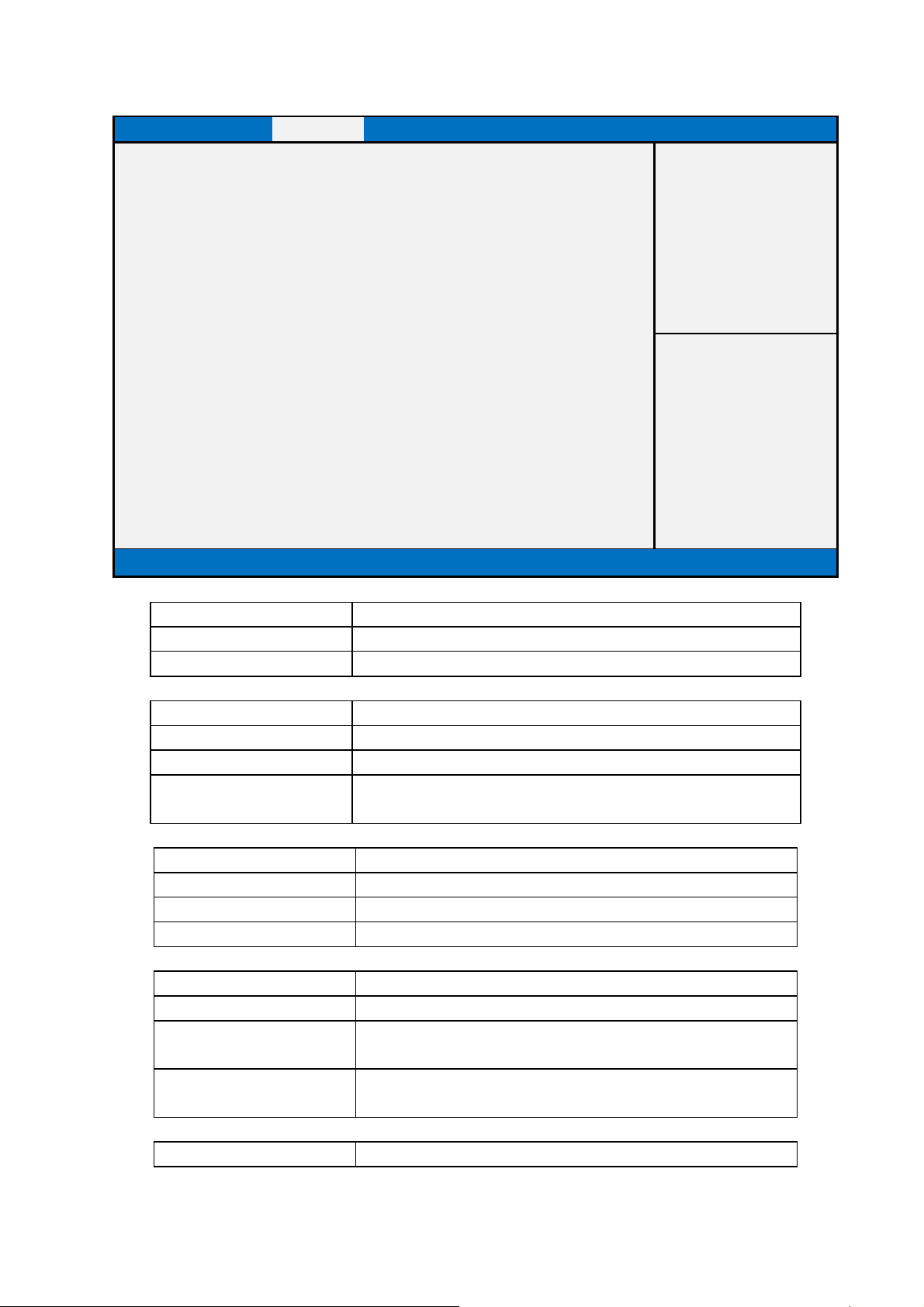
it.
3.2.1 Graphics Configuration
Main Advanced Chipset Boot Security Save & Exit
Graphics Configuration
Item help
Primary VBIOS Version 2177
Primary Display
Internal Graphics
[Auto]
[Auto]
DVMT Pre-Allocated [32M]
DVMT Total Gfx Mem [256M]
LVDS Display [Enabled]
LVDS Panel Type [VBIOS Default]
LVDS Interface Type [Dual Channel]
Version 2.15.1326. Copyright (C) 2012 American Megatrends, Inc.
Field Name
Default Value Primary VBIOS Version
Comment This field is not selectable. There is no help text associated with
Field Name
Default Value [Auto]
Possible Value Auto / IGFX / PCIE / SG
Help Select which of IGFX/PCIE Graphics device should be
Field Name
Default Value [Auto]
Possible Value Auto / Disabled / Enabled
Help Keep IGD enabled based on the setup options.
Field Name
Default Value [32M]
Possible Value 32M / 64M / 96M / 128M / 160M / 192M / 224M / 256M / 288M /
Help Select DVMT 5.0 Pre-Allocated (Fixed) Graphics Memory size
Field Name
Primary VBIOS Version
Primary Display
Primary Display Or select SG for Switchable Gfx.
Internal Graphics
DVMT Pre-Allocated
320M / 352M / 384M / 416M / 448M / 480M / 512M /1024M.
used by the Internal Graphics Device.
DVMT Total Gfx Mem
→←: Select Screen
↑↓: Select Item
Enter: Select
+/- : Change Opt
F1: General Help
F2: Previous Values
F3: Optimized Defaults
F4: Save & Reset
ESC: Exit
54
Page 55
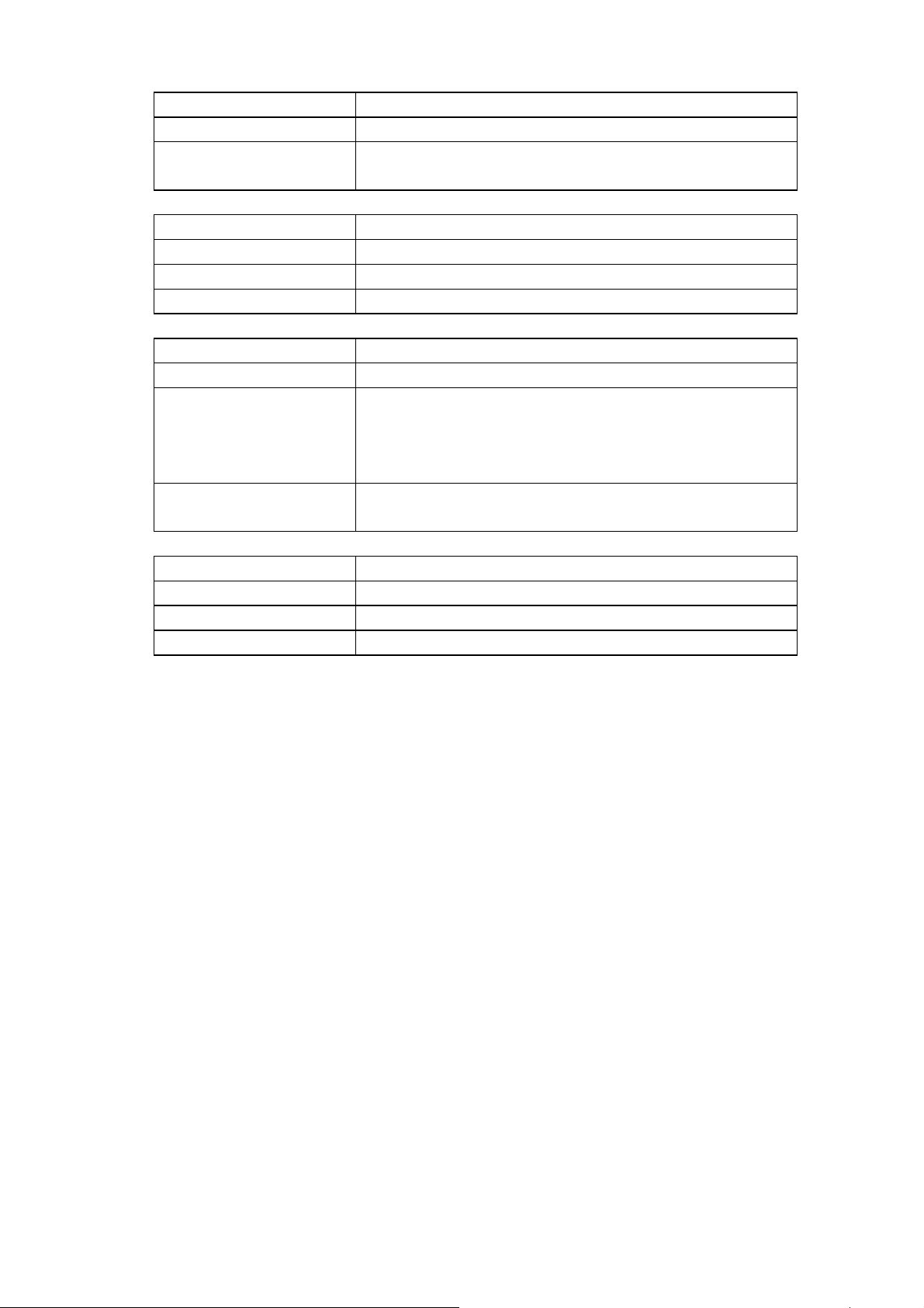
Memory size used by the Internal
Default Value [256M]
Possible Value 128MB / 256MB / MAX
Help Select DVMT5.0 Total Graphic
Graphics Device.
Field Name
Default Value [Enabled]
Possible Value Disabled / Enabled
Help Enable / Disable LVDS display.
Field Name
Default Value [VBIOS Default]
Possible Value VBIOS Default / 640x480 / 800x600 / 1024x768 / 1280x1024 /
Help Select LVDS panel used by Internal Graphics Device by
Field Name
Default Value [Dual Channel]
Possible Value Single Channel / Dual Channel
Help Sets LVDS connectivity.
LVDS Display
LVDS Panel Type
1400x1050(RB) / 1400x1050 / 1600x1200 / 1366x768 /
1680x1050 / 1920x1200 / 1440x900 / 1600x900 / 1024x768 /
1280x800 / 1920x1080 / 2048x1536
selecting the appropriate setup item.
LVDS Interface Type
55
Page 56
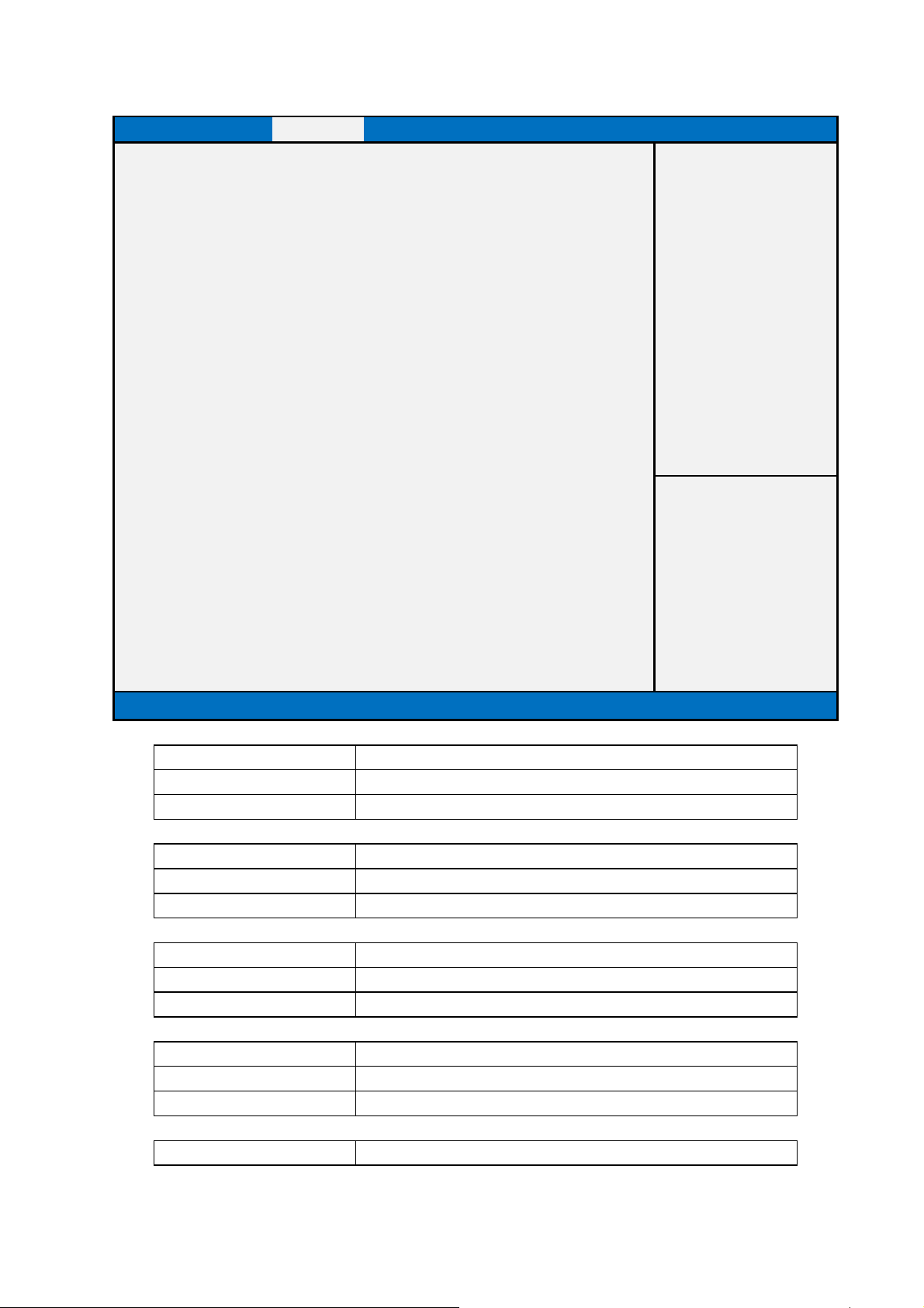
field is not selectable. There is no help text associated with it.
This field is not selectable. There is no help text associated with it.
This field is not selectable. There is no help text associated with it.
This field is not selectable. There is no help text associated with it.
3.2.2 Memory Configuration
Main Advanced Chipset Boot Security Save & Exit
Memory Information
Item help
Memory Frequency 1333 Mhz
Total Memory
Memory Voltage
16384 MB (DDR3)
1.50v
DIMM 0 8192 MB (DDR3)
DIMM 1 8192 MB (DDR3)
CAS Latency (tCL) 9
Minimum delay time
CAS to RAS (tRCDmin) 9
Row Precharge (tRPmin) 9
Active to Precharge
24
(tRASmin)
XMP Profile 1 Not Supported
XMP Profile 2 Not Supported
DIMM profile [Default DIMM profile]
Memory Frequency Limiter [Auto]
Version 2.15.1326. Copyright (C) 2012 American Megatrends, Inc.
→←: Select Screen
↑↓: Select Item
Enter: Select
+/- : Change Opt
F1: General Help
F2: Previous Values
F3: Optimized Defaults
F4: Save & Reset
ESC: Exit
Field Name
Default Value Show Memory Frequency.
Comment This
Field Name
Default Value Total Memory in the System.
Comment
Field Name
Default Value Memory voltage
Comment
Field Name
Default Value Memory in the DIMM.
Comment
Field Name
Memory Frequency
Total Memory
Memory Voltage
DIMM 0
DIMM 1
56
Page 57

This field is not selectable. There is no help text associated with it.
This field is not selectable. There is no help text associated with it.
This field is not selectable. There is no help text associated with it.
help text associated with it.
This field is not selectable. There is no help text associated with it.
is not selectable. There is no help text associated with it.
This field is not selectable. There is no help text associated with it.
Default Value Memory in the DIMM.
Comment
Field Name
Default Value tCL value
Comment
Field Name
Default Value tRCD value
Comment
Field Name
Default Value tRP value
Comment This field is not selectable. There is no
Field Name Active to Precharge (tRASmin)
Default Value tRAS value
Comment
Field Name
Default Value Not Supported
Comment This field
Field Name
Default Value Not Supported
Comment
Field Name
Default Value [Default DIMM profile]
Possible Value Default DIMM profile / Custom Profile / XMP profile 1 /
Help Select DIMM timing profile that should be used.
Field Name
Default Value [Auto]
Possible Value Auto / 1067 / 1333 / 1600 / 1867 / 2133 / 2400 /2667
Help Maximum Memory Frequency Selections in Mhz.
CAS Latency (tCL)
CAS to RAS (tRCDmin)
Row Precharge (tRPmin)
XMP Profile 1
XMP Profile 2
DIMM profile
XMP profile 2
Memory Frequency Limiter
57
Page 58

58
Page 59
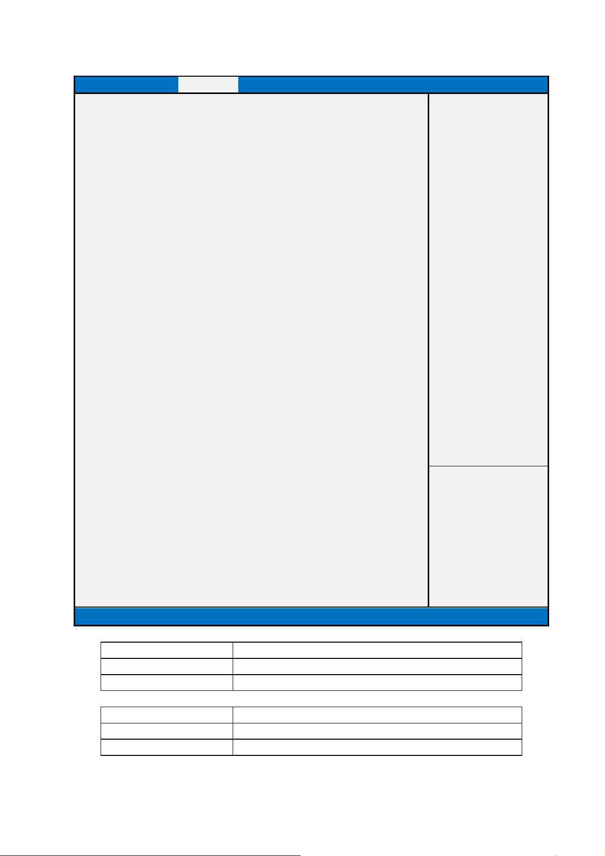
This field is not selectable. There is no help text associated with it.
help text associated with it.
3.2.2.1 Custom Profile Control
Main Advanced Chipset Boot Security Save & Exit
Memory Timing Information
Memory Frequency 1333 Mhz
CAS Latency (tCL) 9
CAS to RAS (tRCDmin)
Row Precharge (tRPmin)
Active to Precharge (tRASmin) 24
Write Recovery (tWRmin) 10
Refresh Recovery (tRFCmin) 107
Row Active to Row Active (tRRDmin) 4
Write to Read Command (tWTRmin) 5
Read to PrechargeCommand(tRTPmin) 5
Four Activate Window (tFAWmin) 20
9
9
Memory Timing Configuration
Memory Frequency Limiter
tCL
tRCD
tRP
tRAS
tWR
tRFC
tRRD
tWTR
tRTP 5
tRC 33
tFAW 20
tCWL value 7
tREFI value 5200
[1333]
15
9
9
24
10
107
4
5
Version 2.15.1326. Copyright (C) 2012 American Megatrends, Inc.
Item help
→←: Select Screen
↑↓: Select Item
Enter: Select
+/- : Change Opt
F1: General Help
F2: Previous Values
F3: Optimized Defaults
F4: Save & Reset
ESC: Exit
Field Name
Default Value Show Memory Frequency.
Comment
Field Name
Default Value tCL value
Comment This field is not selectable. There is no
Memory Frequency
CAS Latency (tCL)
59
Page 60

This field is not selectable. There is no help text associated with it.
not selectable. There is no help text associated with it.
This field is not selectable. There is no help text associated with it.
This field is not selectable. There is no help text associated with it.
This field is not selectable. There is no help text associated with it.
This field is not selectable. There is no help text associated with it.
There is no help text associated with it.
This field is not selectable. There is no help text associated with it.
This field is not selectable. There is no help text associated with it.
Field Name
Default Value tRCD value
Comment
Field Name
Default Value tRP value
Comment This field is
Field Name
Default Value tRAS value
Comment
Field Name
Default Value tWR value
Comment
Field Name
Default Value tRFC value
Comment
Field Name
Default Value tRRD value
Comment
Field Name
Default Value tWTR value
Comment This field is not selectable.
Field Name
Default Value tRTP value
Comment
Field Name
Default Value tFAW value
Comment
Field Name
Default Value Memory Frequency in SPD data
Possible Value 1067 / 1333 / 1600 / 1867 / 2133 / 2400 /2667
Help Maximum Memory Frequency Selections in Mhz.
Field Name
Default Value [15]
CAS to RAS (tRCDmin)
Row Precharge (tRPmin)
Active to Precharge (tRASmin)
Write Recovery (tWRmin)
Refresh Recovery (tRFCmin)
Row Active to Row Active (tRRDmin)
Write to Read Command (tWTRmin)
Read to Precharge Command (tRTPmin)
Four Activate Window (tFAWmin)
Memory Frequency Limiter
tCL
60
Page 61

Possible Value 4 - 18
Help Cas Latency Range 4-18.
Field Name
Default Value [9]
Possible Value 1 - 38
Help Row to Col Delay Range 1-38.
Field Name
Default Value [9]
Possible Value 1 - 38
Help Ras Precharge Range 1-38.
Field Name
Default Value [24]
Possible Value 1 - 586
Help Ras Active Time 1-586.
Field Name
Default Value [10]
Possible Value 1 - 38
Help Min Write Recovery Time Range 1-38.
Field Name
Default Value [107]
Possible Value 1 - 9363
Help Min Refresh Recovery Delay Time 1-9396.
Field Name
Default Value [4]
Possible Value 1 - 38
Help Min Row Active to Row Active Delay Time 1-38.
Field Name
Default Value [5]
Possible Value 1 - 38
Help Min Internal Write to Read Command Delay Time 1-38.
Field Name
Default Value [5]
Possible Value 1 - 38
Help Min Internal Read to Precharge Command Delay Time 1-38.
tRCD
tRP
tRAS
tWR
tRFC
tRRD
tWTR
tRTP
61
Page 62

Field Name
Default Value [33]
Possible Value 1 - 586
Help Min Active to Active/Refresh Delay Time (tRCmin) 1-586.
Field Name
Default Value [20]
Possible Value 1 - 586
Help Min Four Activate Window Delay Time 1-586.
Field Name
Default Value [7]
Possible Value 5 - 12
Help Minimum CAS Write Latency Time (tCWLmin).
Field Name tREFI value
Default Value [5200]
Possible Value 1 - 10000
Help Maximum tREFI Time (Average Periodic Refresh Interval).
tRC
tFAW
tCWL value
62
Page 63
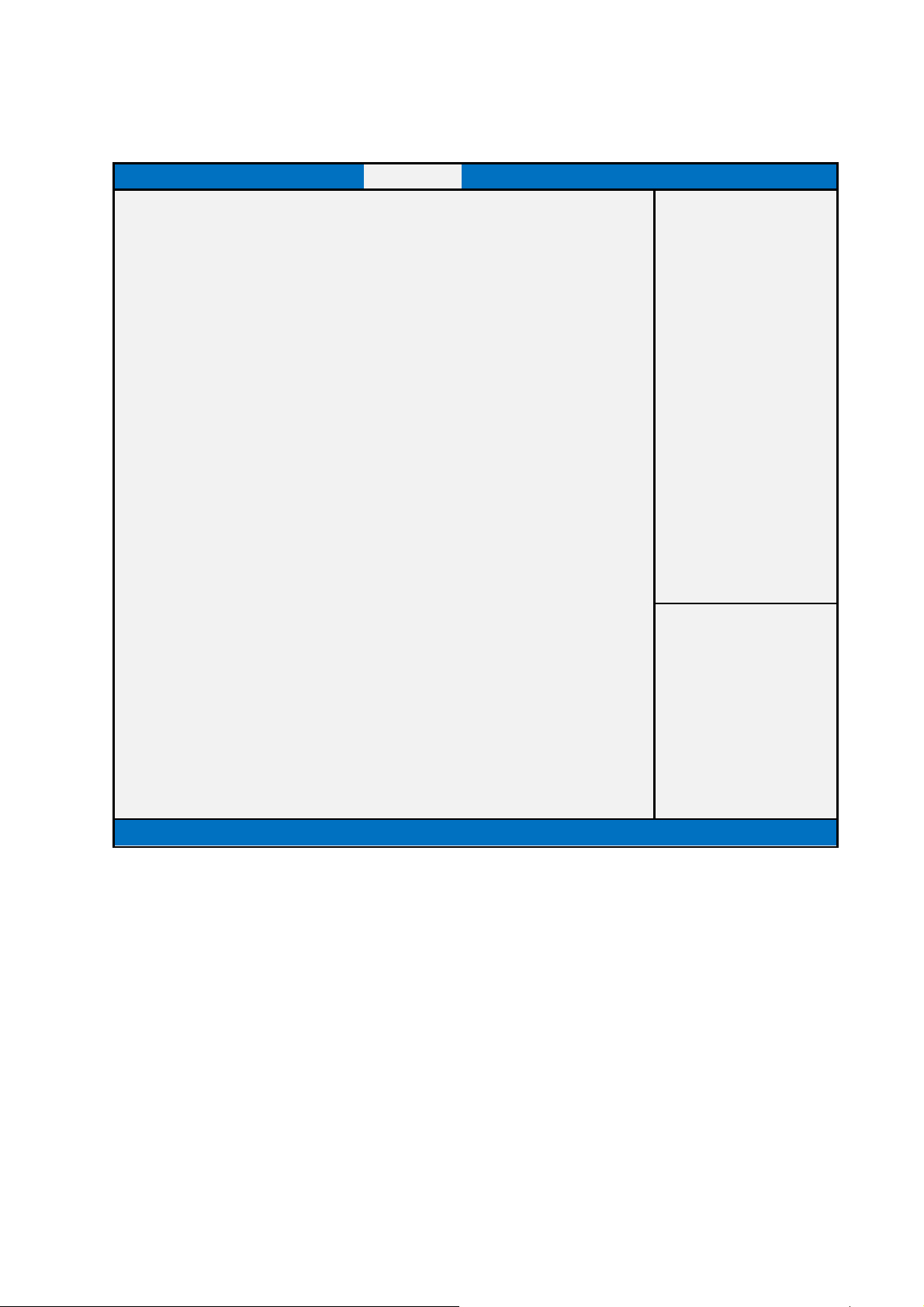
4. Boot
Boot mode select = UEFI
Main Advanced Chipset Boot Security Save & Exit
Boot Configuration
Setup Prompt Timeout 1
Bootup NumLock State [On]
Quiet Boot [Enabled]
Fast Boot [Disabled]
Boot mode select [UEFI]
FIXED BOOT ORDER Priorities
Boot Option #1 [UEFI CD/DVD]
Boot Option #2 [UEFI Hard Disk:Win.]
Boot Option #3 [UEFI USB KEY]
Boot Option #4 [UEFI Network]
Boot Option #5 [UEFI USB CD/DVD]
Boot Option #6 [UEFI USB Hard Disk]
Boot Option Priorities
Boot Option #1
CSM parameters
[Windows Boot Man..]
►UEFI Hard Disk Drive BBS Priorities
Version 2.15.1326. Copyright (C) 2012 American Megatrends, Inc.
Item help
→←: Select Screen
↑↓: Select Item
Enter: Select
+/- : Change Opt
F1: General Help
F2: Previous Values
F3: Optimized Defaults
F4: Save & Reset
ESC: Exit
63
Page 64

Boot mode select = LEGACY
Main Advanced Chipset Boot Security Save & Exit
Boot Configuration
Item help
Setup Prompt Timeout 1
Bootup NumLock State [On]
Quiet Boot [Enabled]
Fast Boot [Disabled]
Boot mode select [Legacy]
FIXED BOOT ORDER Priorities
Boot Option #1 [CD/DVD]
Boot Option #2 [Hard Disk: ST3160..]
Boot Option #3 [USB KEY]
Boot Option #4 [Network]
Boot Option #5 [USB CD/DVD]
Boot Option #6 [USB Hard Disk]
Boot Option #7 [USB Floppy]
Boot Option Priorities
Boot Option #1 [P0: ST3160815AS…]
Hard Drive BBS Priorities
CSM parameters
►Hard Disk Drive BBS Priorities
Version 2.15.1326. Copyright (C) 2012 American Megatrends, Inc.
→←: Select Screen
↑↓: Select Item
Enter: Select
+/- : Change Opt
F1: General Help
F2: Previous Values
F3: Optimized Defaults
F4: Save & Reset
ESC: Exit
64
Page 65

Boot mode select = DUAL
Main Advanced Chipset Boot Security Save & Exit
Boot Configuration
Item help
Setup Prompt Timeout 1
Bootup NumLock State [On]
Quiet Boot [Enabled]
Fast Boot [Disabled]
Boot mode select [DUAL]
FIXED BOOT ORDER Priorities
Boot Option #1 [UEFI CD/DVD]
Boot Option #2 [CD/DVD]
Boot Option #3 [UEFI Hard Disk:Win.]
Boot Option #4 [Hard Disk: ST3160..]
Boot Option #5 [UEFI USB KEY]
Boot Option #6 [USB KEY]
Boot Option #7 [UEFI Network]
Boot Option #8 [Network]
Boot Option #9 [UEFI USB CD/DVD]
Boot Option #10 [USB CD/DVD]
Boot Option #11 [UEFI USB Hard Disk]
Boot Option #12 [USB Hard Disk]
Boot Option #13 [USB Floppy]
Boot Option Priorities
Boot Option #1
Boot Option #2
Hard Drive BBS Priorities
CSM parameters
►Hard Disk Drive BBS Priorities
[Windows Boot Man..]
[P0: ST3160815AS…]
→←: Select Screen
↑↓: Select Item
Enter: Select
+/- : Change Opt
F1: General Help
F2: Previous Values
F3: Optimized Defaults
65
Page 66
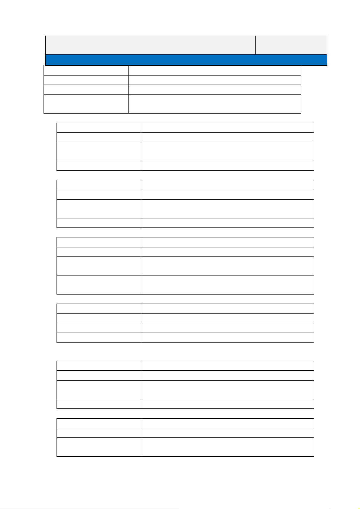
Version 2.15.1326. Copyright (C) 2012 American Megatrends, Inc.
Field Name
Default Value [1]
Possible Value 1~65535
Help Number of seconds to wait for setup activation key.
Field Name
Default Value [On]
Possible Value On
Help Select the keyboard NumLock state
Field Name Quiet Boot
Default Value [Enabled]
Possible Value Enabled
Help Enables or disables Quiet Boot option
Field Name
Default Value [Disabled]
Possible Value Enabled
Help Disable PXE ROM if enable Fast Boot.
Field Name
Default Value [UEFI]
Possible Value LEGACY / UEFI / DUAL
Help Select boot mode LEGACY/UEFI.
Boot mode select = UEFI, FIXED BOOT ORDER Priorities
Field Name
Default Value [UEFI CD/DVD]
Possible Value UEFI CD/DVD, UEFI Hard Disk, UEFI USB KEY, UEFI Network,
Help Sets the system boot order.
Field Name Boot Option #2
Default Value [UEFI Hard Disk]
Possible Value UEFI CD/DVD, UEFI Hard Disk, UEFI USB KEY, UEFI Network,
Setup Prompt Timeout
65535(0xFFFF) means indefinite waiting.
Boot NumLock State
Off
Disabled
Fast Boot
Disabled
Boot mode select
Boot Option #1
UEFI USB CD/DVD,UEFI USB Hard Disk, Disabled.
UEFI USB CD/DVD,UEFI USB Hard Disk, Disabled.
F4: Save & Reset
ESC: Exit
66
Page 67

Help Sets the system boot order.
Field Name
Default Value [UEFI USB Key]
Possible Value UEFI CD/DVD, UEFI Hard Disk, UEFI USB KEY, UEFI Network,
Help Sets the system boot order.
Field Name
Default Value [UEFI Network]
Possible Value UEFI CD/DVD, UEFI Hard Disk, UEFI USB KEY, UEFI Network,
Help Sets the system boot order.
Field Name
Default Value [UEFI USB CD/DVD]
Possible Value UEFI CD/DVD, UEFI Hard Disk, UEFI USB KEY, UEFI Network,
Help Sets the system boot order.
Field Name
Default Value [UEFI USB Hard Disk]
Possible Value UEFI CD/DVD, UEFI Hard Disk, UEFI USB KEY, UEFI Network,
Help Sets the system boot order.
Boot Option #3
UEFI USB CD/DVD,UEFI USB Hard Disk, Disabled.
Boot Option #4
UEFI USB CD/DVD,UEFI USB Hard Disk, Disabled.
Boot Option #5
UEFI USB CD/DVD,UEFI USB Hard Disk, Disabled.
Boot Option #6
UEFI USB CD/DVD,UEFI USB Hard Disk, Disabled.
Boot mode select = LEGACY, FIXED BOOT ORDER Priorities.
Field Name
Default Value [CD/DVD]
Possible Value CD/DVD, Hard Disk, USB KEY, Network, USB CD/DVD,
Help Sets the system boot order.
Field Name
Default Value [Hard Disk]
Possible Value CD/DVD, Hard Disk, USB KEY, Network, USB CD/DVD,
Help Sets the system boot order.
Field Name
Default Value [USB Key]
Possible Value CD/DVD, Hard Disk, USB KEY, Network, USB CD/DVD,
Boot Option #1
USB Hard Disk, USB Floppy, Disabled.
Boot Option #2
USB Hard Disk, USB Floppy, Disabled.
Boot Option #3
USB Hard Disk, USB Floppy, Disabled.
67
Page 68

Help Sets the system boor order.
Field Name
Default Value [Network]
Possible Value CD/DVD, Hard Disk, USB KEY, Network, USB CD/DVD,
Help Sets the system boot order.
Field Name
Default Value [USB CD/DVD]
Possible Value CD/DVD, Hard Disk, USB KEY, Network, USB CD/DVD,
Help Sets the system boot order.
Field Name
Default Value [USB Hard Disk]
Possible Value CD/DVD, Hard Disk, USB KEY, Network, USB CD/DVD,
Help Sets the system boot order.
Field Name
Default Value [USB Floppy]
Possible Value CD/DVD, Hard Disk, USB KEY, Network, USB CD/DVD,
Help Sets the system boot order.
Boot Option #4
USB Hard Disk, USB Floppy, Disabled.
Boot Option #5
USB Hard Disk, USB Floppy, Disabled.
Boot Option #6
USB Hard Disk, USB Floppy, Disabled.
Boot Option #7
USB Hard Disk, USB Floppy, Disabled.
Boot mode select = DUAL, FIXED BOOT ORDER Priorities.
Field Name
Default Value [UEFI CD/DVD]
Possible Value UEFI CD/DVD, CD/DVD, UEFI Hard Disk, Hard Disk,
Help Sets the system boot order.
Field Name
Default Value [CD/DVD]
Possible Value UEFI CD/DVD, CD/DVD, UEFI Hard Disk, Hard Disk,
Help Sets the system boot order.
Field Name
Boot Option #1
UEFI USB Key, USB Key, UEFI Network, Network,
UEFI USB CD/DVD, USB CD/DVD, UEFI USB Hard Disk,
USB Hard Disk, USB Floppy, Disabled.
Boot Option #2
UEFI USB Key, USB Key, UEFI Network, Network,
UEFI USB CD/DVD, USB CD/DVD, UEFI USB Hard Disk,
USB Hard Disk, USB Floppy, Disabled.
Boot Option #3
68
Page 69

Default Value [UEFI Hard Disk]
Possible Value UEFI CD/DVD, CD/DVD, UEFI Hard Disk, Hard Disk,
UEFI USB Key, USB Key, UEFI Network, Network,
UEFI USB CD/DVD, USB CD/DVD, UEFI USB Hard Disk,
USB Hard Disk, USB Floppy, Disabled.
Help Sets the system boot order.
Field Name
Default Value [Hard Disk]
Possible Value UEFI CD/DVD, CD/DVD, UEFI Hard Disk, Hard Disk,
Help Sets the system boot order.
Field Name Boot Option #5
Default Value [UEFI USB Key]
Possible Value UEFI CD/DVD, CD/DVD, UEFI Hard Disk, Hard Disk,
Help Sets the system boot order.
Field Name
Default Value [USB Key]
Possible Value UEFI CD/DVD, CD/DVD, UEFI Hard Disk, Hard Disk,
Help Sets the system boot order.
Field Name
Default Value [UEFI Network]
Possible Value UEFI CD/DVD, CD/DVD, UEFI Hard Disk, Hard Disk,
Help Sets the system boot order.
Field Name
Default Value [Network]
Possible Value UEFI CD/DVD, CD/DVD, UEFI Hard Disk, Hard Disk,
Boot Option #4
UEFI USB Key, USB Key, UEFI Network, Network,
UEFI USB CD/DVD, USB CD/DVD, UEFI USB Hard Disk,
USB Hard Disk, USB Floppy, Disabled.
UEFI USB Key, USB Key, UEFI Network, Network,
UEFI USB CD/DVD, USB CD/DVD, UEFI USB Hard Disk,
USB Hard Disk, USB Floppy, Disabled.
Boot Option #6
UEFI USB Key, USB Key, UEFI Network, Network,
UEFI USB CD/DVD, USB CD/DVD, UEFI USB Hard Disk,
USB Hard Disk, USB Floppy, Disabled.
Boot Option #7
UEFI USB Key, USB Key, UEFI Network, Network,
UEFI USB CD/DVD, USB CD/DVD, UEFI USB Hard Disk,
USB Hard Disk, USB Floppy, Disabled.
Boot Option #8
UEFI USB Key, USB Key, UEFI Network, Network,
UEFI USB CD/DVD, USB CD/DVD, UEFI USB Hard Disk,
69
Page 70

USB Hard Disk, USB Floppy, Disabled.
Help Sets the system boot order.
Field Name
Default Value [UEFI USB CD/DVD]
Possible Value UEFI CD/DVD, CD/DVD, UEFI Hard Disk, Hard Disk,
Help Sets the system boot order.
Field Name
Default Value [USB CD/DVD]
Possible Value UEFI CD/DVD, CD/DVD, UEFI Hard Disk, Hard Disk,
Help Sets the system boot order.
Field Name
Default Value [UEFI USB Hard Disk]
Possible Value UEFI CD/DVD, CD/DVD, UEFI Hard Disk, Hard Disk,
Help Sets the system boot order.
Field Name
Default Value [USB Hard Disk]
Possible Value UEFI CD/DVD, CD/DVD, UEFI Hard Disk, Hard Disk,
Help Sets the system boot order.
Field Name
Default Value [USB Floppy]
Possible Value UEFI CD/DVD, CD/DVD, UEFI Hard Disk, Hard Disk,
Boot Option #9
UEFI USB Key, USB Key, UEFI Network, Network,
UEFI USB CD/DVD, USB CD/DVD, UEFI USB Hard Disk,
USB Hard Disk, USB Floppy, Disabled.
Boot Option #10
UEFI USB Key, USB Key, UEFI Network, Network,
UEFI USB CD/DVD, USB CD/DVD, UEFI USB Hard Disk,
USB Hard Disk, USB Floppy, Disabled.
Boot Option #11
UEFI USB Key, USB Key, UEFI Network, Network,
UEFI USB CD/DVD, USB CD/DVD, UEFI USB Hard Disk,
USB Hard Disk, USB Floppy, Disabled.
Boot Option #12
UEFI USB Key, USB Key, UEFI Network, Network,
UEFI USB CD/DVD, USB CD/DVD, UEFI USB Hard Disk,
USB Hard Disk, USB Floppy, Disabled.
Boot Option #13
UEFI USB Key, USB Key, UEFI Network, Network,
UEFI USB CD/DVD, USB CD/DVD, UEFI USB Hard Disk,
USB Hard Disk, USB Floppy, Disabled.
70
Page 71

Help Sets the system boot order.
BOOT Option Priorities
Field Name
Default Value [Boot device name]
Possible Value All Boot devices name.
Help Sets the system boot order.
Field Name
Help Sets the order of the legacy devices in this group.
Comment Press Enter when selected to go into the associated Sub-Menu.
Field Name
Help Sets the order of the legacy devices in this group.
Comment Press Enter when selected to go into the associated Sub-Menu.
Field Name
Help Sets the order of the legacy devices in this group.
Comment Press Enter when selected to go into the associated Sub-Menu.
Field Name USB Device BBS Priorities
Help Sets the order of the legacy devices in this group.
Comment Press Enter when selected to go into the associated Sub-Menu.
Field Name
Help Sets the order of the legacy devices in this group.
Comment Press Enter when selected to go into the associated Sub-Menu.
Field Name
Help OpROM execution, boot options filter, etc.
Comment Press Enter when selected to go into the associated Sub-Menu.
Field Name
Help Specifies the Boot Device Priority sequence from available
Comment Press Enter when selected to go into the associated Sub-Menu.
Field Name
Help Specifies the Boot Device Priority sequence from available Hard
Comment Press Enter when selected to go into the associated Sub-Menu.
Boot Option #1 / Boot Option #2 / …
Hard Drive BBS Priorities
CD/DVD ROM BBS Priorities
Network BBS Priorities
Unknown Device BBS Priorities
CSM parameters
CD/DVD ROM Drive BBS Priorities
CD/DVD ROM Drives.
Hard Disk Drive BBS Priorities
Disk Drives.
Field Name
Help Specifies the Boot Device Priority sequence from available
NETWORK Drive BBS Priorities
71
Page 72

UEFI
UEFI
UEFI
UEFI
NETWORK Drives.
Comment Press Enter when selected to go into the associated Sub-Menu.
Field Name
Help Specifies the Boot Device Priority sequence from available USB
Comment Press Enter when selected to go into the associated Sub-Menu.
USB CD/DVD ROM Drive BBS Priorities
CD/DVD ROM Drives.
Field Name
Help Specifies the Boot Device Priority sequence from available USB
Comment Press Enter when selected to go into the associated Sub-Menu.
USB Hard Disk Drive BBS Priorities
Hard Disk Drives
Field Name
Help Specifies the Boot Device Priority sequence from available USB
Comment Press Enter when selected to go into the associated Sub-Menu.
USB KEY Drive BBS Priorities
Key Drives.
Field Name
Help Specifies the Boot Device Priority sequence from available USB
Comment Press Enter when selected to go into the associated Sub-Menu.
Field Name
Help Specifies the Boot Device Priority sequence from available
Comment Press Enter when selected to go into the associated Sub-Menu.
Field Name
Help Specifies the Boot Device Priority sequence from available
Comment Press Enter when selected to go into the associated Sub-Menu.
USB Floppy Drive BBS Priorities
Floppy Drives.
UEFI CD/DVD ROM Drive BBS Priorities
CD/DVD ROM Drives.
UEFI Hard Disk Drive BBS Priorities
Hard Disk Drives.
Field Name
Help Specifies the Boot Device Priority sequence from available
Comment Press Enter when selected to go into the associated Sub-Menu.
UEFI NETWORK Drive BBS Priorities
NETWORK Drives.
Field Name
Help Specifies the Boot Device Priority sequence from available
Comment Press Enter when selected to go into the associated Sub-Menu.
UEFI USB CD/DVD ROM Drive BBS Priorities
USB CD/DVD ROM Drives.
72
Page 73

UEFI
UEFI
Field Name
Help Specifies the Boot Device Priority sequence from available
Comment Press Enter when selected to go into the associated Sub-Menu.
UEFI USB Hard Disk Drive BBS Priorities
USB Hard Disk Drives.
Field Name
Help Specifies the Boot Device Priority sequence from available
Comment Press Enter when selected to go into the associated Sub-Menu.
UEFI USB KEY Drive BBS Priorities
USB Key Drives.
73
Page 74
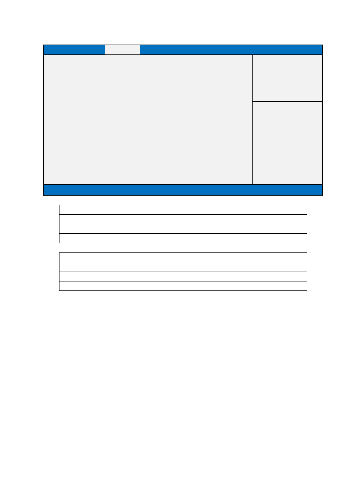
4.1 CSM parameters
Main Advanced Chipset Boot Security Save & Exit
Item help
Launch CSM [Enabled]
Launch PXE OpROM policy [Do not launch]
Version 2.15.1326. Copyright (C) 2012 American Megatrends, Inc.
Field Name
Default Value [Enabled]
Possible Value Enabled / Disabled
Help This option controls if CSM will be launched.
Field Name
Default Value [Do not launch]
Possible Value Do not launch / UEFI only / Legacy only
Help Controls the execution of UEFI and Legacy PXE OpROM.
Launch CSM
Launch PXE OpROM policy
→←: Select Screen
↑↓: Select Item
Enter: Select
+/- : Change Opt
F1: General Help
F2: Previous Values
F3: Optimized Defaults
F4: Save & Reset
ESC: Exit
74
Page 75
5. Security
Main Advanced Chipset Boot Security Save & Exit
Password Description
If Only the Administrator's password is set
then this only limits access to Setup and is
only asked for when entering Setup
If ONLY the User’s password is set, then this
Is a power on password and must be entered to
boot or enter Setup. In Setup the User will.
have Administrator rights.
The password length must be
in the following range:
Minimum Length 3
Maximum Length 20
Administrator Password
User Password
►Secure Boot menu
HDD Security Configuration
P0:WDC WD6400AA
Version 2.15.1326. Copyright (C) 2012 American Megatrends, Inc.
Item help
→←: Select Screen
↑↓: Select Item
Enter: Select
+/- : Change Opt
F1: General Help
F2: Previous Values
F3: Optimized Defaults
F4: Save & Reset
ESC: Exit
Field Name
Help Set Administrator Password
Comment Press Enter when selected to go into the associated Sub-Menu.
Field Name
Help Set Setup User Password.
Comment Press Enter when selected to go into the associated Sub-Menu.
Field Name
Help Customizable Secure Boot settings.
Comment Press Enter when selected to go into the associated Sub-Menu.
Field Name
Administrator Password
User Password
Note: Only can modify System Date, System Timer, I217, and
I210 options if User Password.
Secure Boot menu
HDD Security Configuration:
P0: WDC WD6400AA
75
Page 76

Help Set HDD password
Comment Press Enter when selected to go into the associated Sub-Menu.
76
Page 77
5.1 Secure Boot menu
Main Advanced Chipset Boot Security Save & Exit
System Mode
Secure Boot
Setup
Not Active
Item help
Secure Boot Support [Enabled]
Secure Boot Mode [Standard]
►Key Management
Version 2.15.1326. Copyright (C) 2012 American Megatrends, Inc.
→←: Select Screen
↑↓: Select Item
Enter: Select
+/- : Change Opt
F1: General Help
F2: Previous Values
F3: Optimized Defaults
F4: Save & Reset
ESC: Exit
Field Name
Default Value [Enabled]
Possible Value Enabled / Disabled
Help Secure Boot can be enabled if 1.System running in User mode
Field Name
Default Value [Standard]
Possible Value Standard / Custom
Help Secure Boot mode selector. ‘Custom’ Mode enables user to
Secure Boot Support
with enrolled Platform Key(PK) 2.CSM function is disabled.
Secure Boot Mode
change Image Execution policy and Secure Boot Keys
77
Page 78
5.1.1 Key Management
Main Advanced Chipset Boot Security Save & Exit
Factory Default Key Provisioning
►Install All Factory Default Keys
[Disabled]
Item help
►Save All Secure Boot Variables
Platform Key (PK) NOT INSTALLED
►Delete PK
►Set new PK
Key Exchange Key Database (KEK) NOT INSTALLED
►Delete KEK
►Set new KEK
►Append KEK
Authorized Signature
NOT INSTALLED
→←: Select Screen
↑↓: Select Item
Enter: Select
+/- : Change Opt
F1: General Help
F2: Previous Values
F3: Optimized Defaults
Database(DB)
►Delete DB
►Set new DB
►Append DB
Forbidden Signature Database(DBX) NOT INSTALLED
►Delete DBX
►Set new DBX
►Append DBX
Version 2.15.1326. Copyright (C) 2012 American Megatrends, Inc.
F4: Save & Reset
ESC: Exit
Field Name
Default Value [Disabled]
Possible Value Enabled / Disabled
Help Install Factory default Secure Boot Keys when System is in
Field Name
Help Force System to User Mode - install all Factory Default
Comment
Field Name
Help Force System to User Mode - clear all Factory Default
Comment
Factory Default Key Provisioning
Setup Mode.
Install All Factory Default Keys
keys(PK,KEK,db,dbx). Change takes effect after reboot
Delete All Factory Default Key
keys(PK,KEK,db,dbx). Change takes effect after reboot
78
Page 79
Field Name
Help Store content of each Secure Boot Variable(data formatted as
Comment
Save All Secure Boot Variables
EFI_SIGNATURE_LIST) to a file with matching name on
selected file system’s root folder
Field Name
Help Delete the Variable from NVRAM. Removing PK will reset
Comment
Delete PK
System to Setup Mode
Field Name
Help Insert Factory Default Keys or load from a file formatted as:
Comment
Set new PK
1. Public Key Certificate in : a) EFI_SIGNATURE_LIST, b)
EFI_CERT_X509 (DER encoded), c) EFI_CERT_RSA2048
(bin), d) EFI_CERT_SHA256 (bin).
2. Efi Time-Based Authenticated Variable
Field Name
Help Delete the Variable from NVRAM. Removing KEK will reset
Comment
Delete KEK
System to Setup Mode
Field Name
Help Insert Factory Default Keys or load from a file formatted as:
Comment
Set new KEK
1. Public Key Certificate in : a) EFI_SIGNATURE_LIST, b)
EFI_CERT_X509 (DER encoded), c) EFI_CERT_RSA2048
(bin), d) EFI_CERT_SHA256 (bin).
2. Efi Time-Based Authenticated Variable
Field Name
Help Insert Factory Default Keys or load from a file formatted as:
Comment
Append KEK
1. Public Key Certificate in : a) EFI_SIGNATURE_LIST, b)
EFI_CERT_X509 (DER encoded), c) EFI_CERT_RSA2048
(bin), d) EFI_CERT_SHA256 (bin).
2. Efi Time-Based Authenticated Variable
Field Name
Help Delete the Variable from NVRAM. Removing DB will reset
Delete DB
System to Setup Mode
79
Page 80
Comment
Field Name
Help Insert Factory Default Keys or load from a file formatted as:
Comment
Set new DB
1. Public Key Certificate in : a) EFI_SIGNATURE_LIST, b)
EFI_CERT_X509 (DER encoded), c) EFI_CERT_RSA2048
(bin), d) EFI_CERT_SHA256 (bin).
2. Efi Time-Based Authenticated Variable
Field Name
Help Insert Factory Default Keys or load from a file formatted as:
Comment
Append DB
1. Public Key Certificate in : a) EFI_SIGNATURE_LIST, b)
EFI_CERT_X509 (DER encoded), c) EFI_CERT_RSA2048
(bin), d) EFI_CERT_SHA256 (bin).
2. Efi Time-Based Authenticated Variable
Field Name
Help Delete the Variable from NVRAM. Removing DBX will reset
Comment
Delete DBX
System to Setup Mode
Field Name
Help Insert Factory Default Keys or load from a file formatted as:
Comment
Set new DBX
1. Public Key Certificate in : a) EFI_SIGNATURE_LIST, b)
EFI_CERT_X509 (DER encoded), c) EFI_CERT_RSA2048
(bin), d) EFI_CERT_SHA256 (bin).
2. Efi Time-Based Authenticated Variable
Field Name
Help Insert Factory Default Keys or load from a file formatted as:
Comment
Append DBX
1. Public Key Certificate in : a) EFI_SIGNATURE_LIST, b)
EFI_CERT_X509 (DER encoded), c) EFI_CERT_RSA2048
(bin), d) EFI_CERT_SHA256 (bin).
2. Efi Time-Based Authenticated Variable
80
Page 81
5.2 HDD Security Configuration
Main Advanced Chipset Boot Security Save & Exit
HDD Password Description
Allow Access to Set, Modify and Clear
Item help
Hard Disk User Password. User Password
need to be installed for Enabling Security.
HDD PASSWORD CONFIGURATION:
Security
Yes
→←: Select Screen
Supported :
Security
No
↑↓: Select Item
Enabled :
Security
No
Enter: Select
Locked :
Security
No
+/- : Change Opt
Frozen :
HDD User Pwd Status NOT INSTALLED
Set User Password
Version 2.15.1326. Copyright (C) 2012 American Megatrends, Inc.
F1: General Help
F2: Previous Values
F3: Optimized Defaults
F4: Save & Reset
ESC: Exit
Field Name
Help Set HDD User Password
Comment Press Enter when selected to go into the associated Sub-Menu.
Set User Password
81
Page 82
6. Save & Exit
Main Advanced Chipset Boot Security Save & Exit
Save Changes and Reset
Discard Changes and Reset
Discard Changes and Exit
Restore Defaults
Save as User Defaults
Restore User Defaults
Boot Override
Version 2.15.1326. Copyright (C) 2012 American Megatrends, Inc.
Item help
→←: Select Screen
↑↓: Select Item
Enter: Select
+/- : Change Opt
F1: General Help
F2: Previous Values
F3: Optimized Defaults
F4: Save & Reset
ESC: Exit
Field Name
Help Reset the system after saving the changes.
Comment
Field Name
Help Reset system setup without saving any changes.
Comment
Field Name
Help Exit system setup without saving any changes.
Comment
Field Name
Help Restore Default values for all the setup options.
Comment
Field Name
Save Changes and Reset
Discard Changes and Reset
Discard Changes and Exit
Restore Defaults
Save as User Defaults
82
Page 83

Help Save the changes done so far as User Defaults.
Comment
Field Name
Help Restore the User Defaults to all the setup options.
Comment
Restore User Defaults
83
 Loading...