

Page 1

MITAC Desktop Board
PH11SI
Product Guide
Page 2
Form Factor
CPU Type : Intel Skylake
-
S Desktop platform
Chipset
Integrated GFX by CPU
Memory Socket: 260
-
pin So-
DIMM socket
2
Memory
Type:
DDR4
@ 1.2V
, 2133MHz (
Unbuffered
SIO Controller
LAN
Audio
Codec: HD audio codec,
Realtek ALC662
Display
PCI-E Mini Card (Half)
x 1
, Signal: PCIe, USB2.0
PCI-E Mini Card (Full)
x 1
, Signal: PCIe, SATA3.0
HD-out 1
VGA out
1
USB3.0
4
RJ-45 (
with integrated status LED
s) 1
Line-out 1
Mic-in 1
DC-in Jack
(19V DC
;
5mm/ ID, 7.5mm/ OD)
1
LVDS connector
1
Converter BD header
1
Light sensor header
1
USB 2.0 header
5
SATA Connector
2
SATA Power
1
CPU Fan header
1
Desktop Board Features
This chapter briefly describes the features of Desktop Board PH11SI.
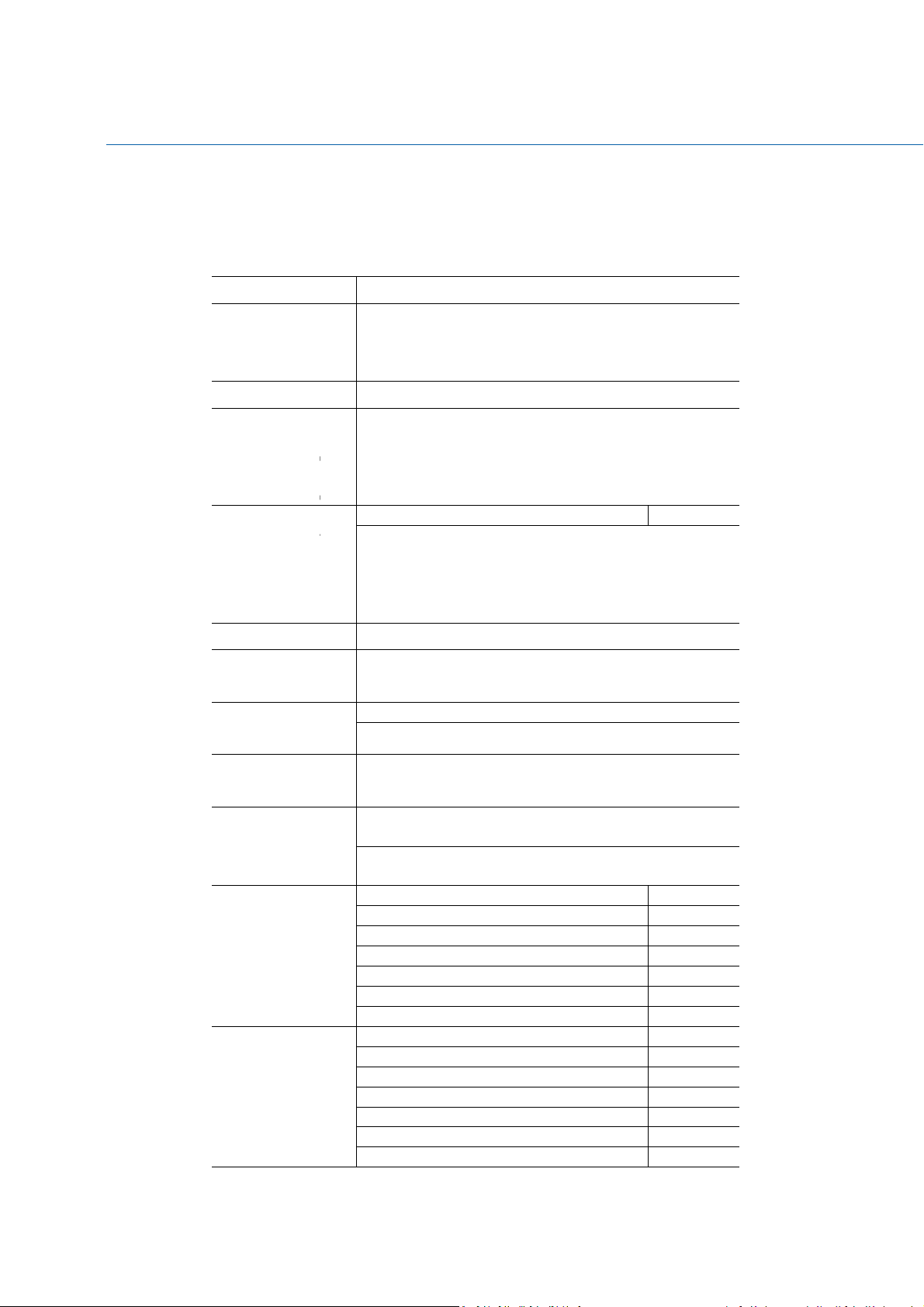
Table 1 summarizes the major features of the Desktop Board.
Feature Summary
Processor
Graphics
Memory
Thin Mini-iTX (170mm x 170mm), 6 layers
CPU Core : Dual Core / Quad Core
Socket : Socket LGA1151
TDP : Support up to 65W CPU types
Chipset Series : Intel® H110 Chipset
Graphic Core : Gen9
Graphic Memory : Shared Memory
3D : DX12, OpenGL 4.3/4.4
Computing : OpenCL 2.0
Non-ECC)
Memory Channel: Dual Channel
Memory Capacity : Support total up to 16 GB
ECC Support : No
IT8519E
Controller
Controller
Controller
Expansion slot
External I/O
Internal I/O
Realtek RTL8111G, 10/100/1000 support
AMP for internal speaker
Parade DP701
for WiFi/BT module
for mSATA or TV card
2
Page 3

Speaker header
1
Side SW/LED header
1
DMIC header
1
19V 2 pin power header (Option#1)
Option#1: 19V DC
-
in, 19V 2pin power header
CE
12V 4 pin power header (Option#2)
Power
BIOS
Compliance
T
AB L E
Option#2: 12V DC-in, 12V 4pin power header
AMI BIOS
FCC
1. MITA C D
ES K T O P BOA R D
PH11SI F
EA T U RES
3
Page 4
Desktop Board Components
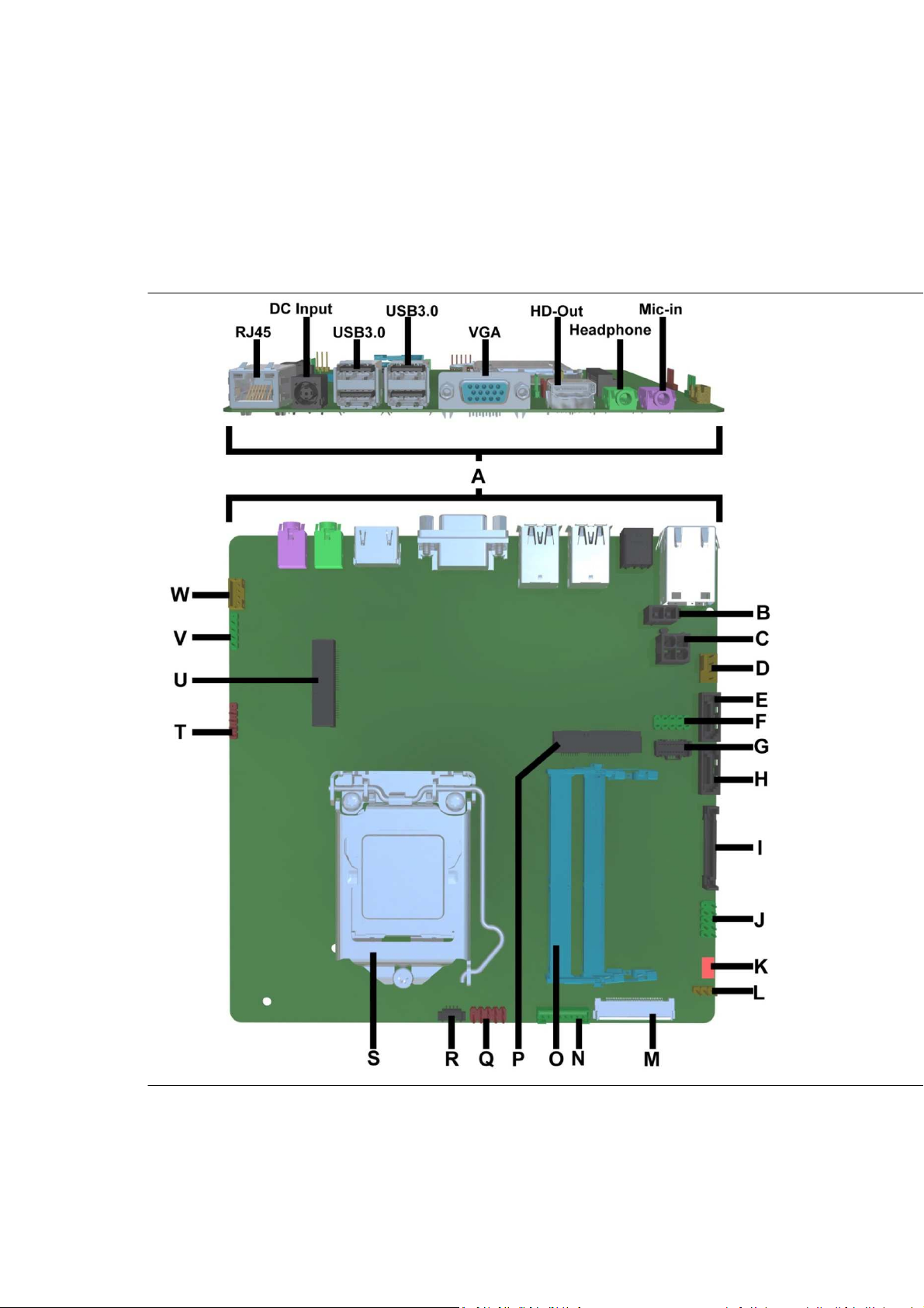
Figure 1 shows the approximate location of the major components on the top side of
MiTAC Desktop Board PH11SI.
Figu re 1 . MiT A C D es k t o p Bo a r d PH 11SI C o m p on e nts ( T op)
4
Page 5

A Back
P
anel
C
onnectors
B 12V out for Wireless charger Module (
For MiTAC AiO)
C 12V in for Wireless charger Module
D Fan Connector
E SATA connector
F Dual-Port USB 2.0 Header
G Front I/O header
(For MiTAC AiO)
H SATA connector
I SATA power connector
J Front I/O header
K CPU FAN header
L B
acklight power selec
t
M LVDS connector
N B
acklight power header
O DIMM sockets
P Mini PCIE slot (full length)
Q Dual-Port USB 2.0 Header
for
TP &Card reader
header (For MiTAC AiO)
R NFC/RFID
header (For MiTAC AiO)
S CPU socket
T Single
-
Port USB 2.0 Header
for
WebCAM
header (For MiTAC AiO)
U Mini PCIE slot (half length)
V Single USB 2.0 Header
for DMIC (For MiTAC AiO)
W Internal speaker
T
AB L E
2. MITA C D
ES K T OP BOA R D
PH11SI C
OM P ONEN T S
( S
HO W N IN FIG U R E
1 )
5
Page 6

Processor
The board supports 6th generation Intel Core processors. Other processors may be
supported in the future. This board supports processors with a maximum wattage of
65 W Thermal Design Power (TDP).
NOTE
This board has specific requirements for providing power to the processor. Additional
power required will depend on configurations chosen by the integrator.
System Memory
NOTE
To be fully compliant with all applicable DDR SDRAM memory specifications, the board
should be populated with DIMMs that support the Serial Presence Detect (SPD) data
structure. This allows the BIOS to read the SPD data and program the chipset to
accurately configure memory settings for optimum performance. If non-SPD memory
is installed, the BIOS will attempt to correctly configure the memory settings, but
performance and reliability may be impacted or the DIMMs may not function under the
determined frequency.
The Desktop Board has tw o260-pin DDR4 SO-DIMM sockets with gold-plated contacts.
6
Page 7
Connecting to the Internal Headers and Connectors
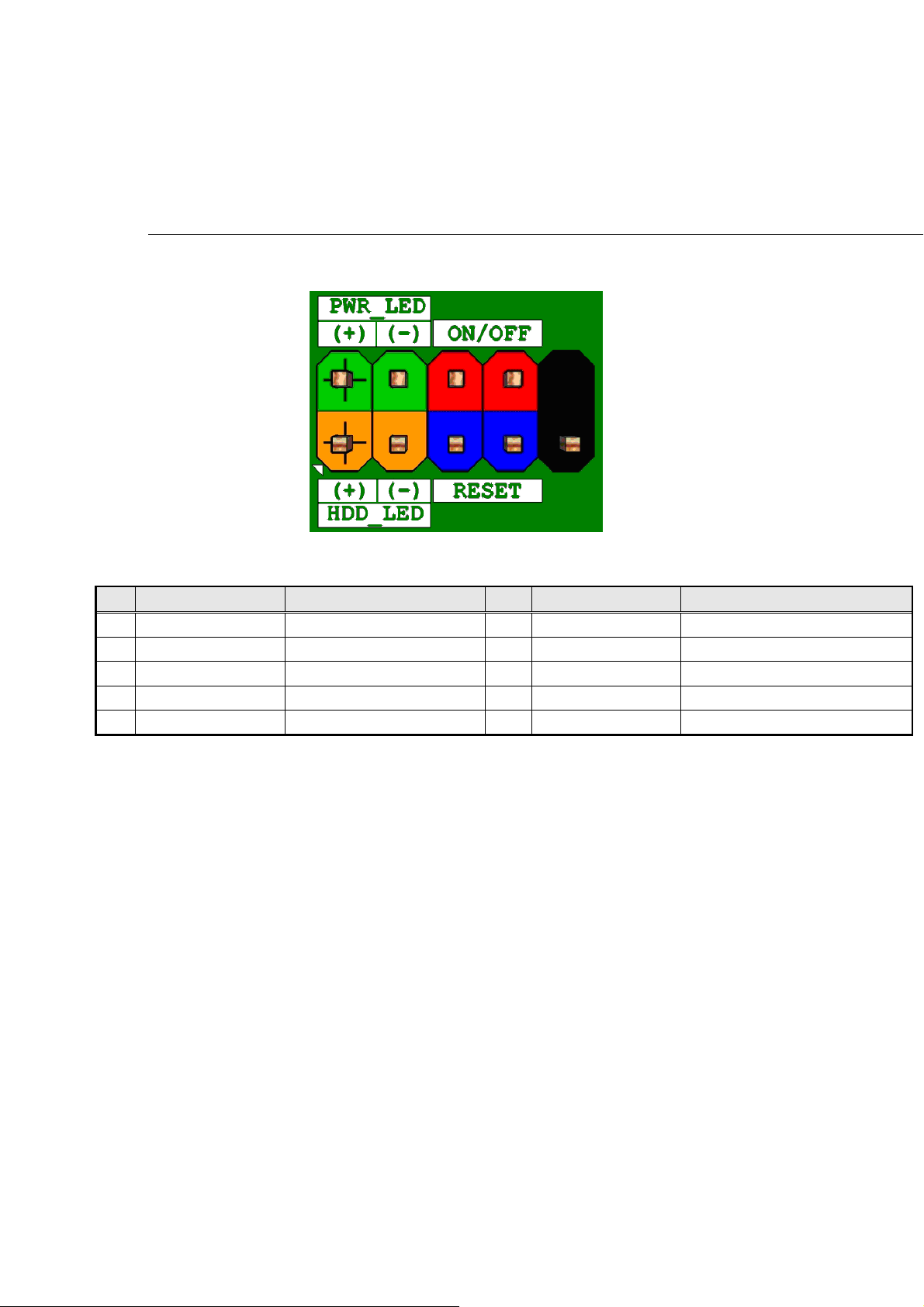
Front panel main header
Figure 2 Front pan el mai n h e a der pi n -ou t
Pin Signal Name Description Pin Signal Name Description
1 HDD_POWER_LED Pull-up resistor (750) to +5V 2 POWER_LED_MAIN [Out] Front panel LED (main color)
3 HDD_LED# [Out] Hard disk activity LED 4 POWER_LED_ALT [Out] Front panel LED (alt color)
5 GROUND Ground 6 POWER_SWITCH# [In] Power switch
7 RESET_SWITCH# [In] Reset switch 8 GROUND Ground
9 +5V_DC Power 10 KEY No pin
T
AB L E 2 FRO N T PANE L MAIN H EADE R SIGNA L S
7
Page 8
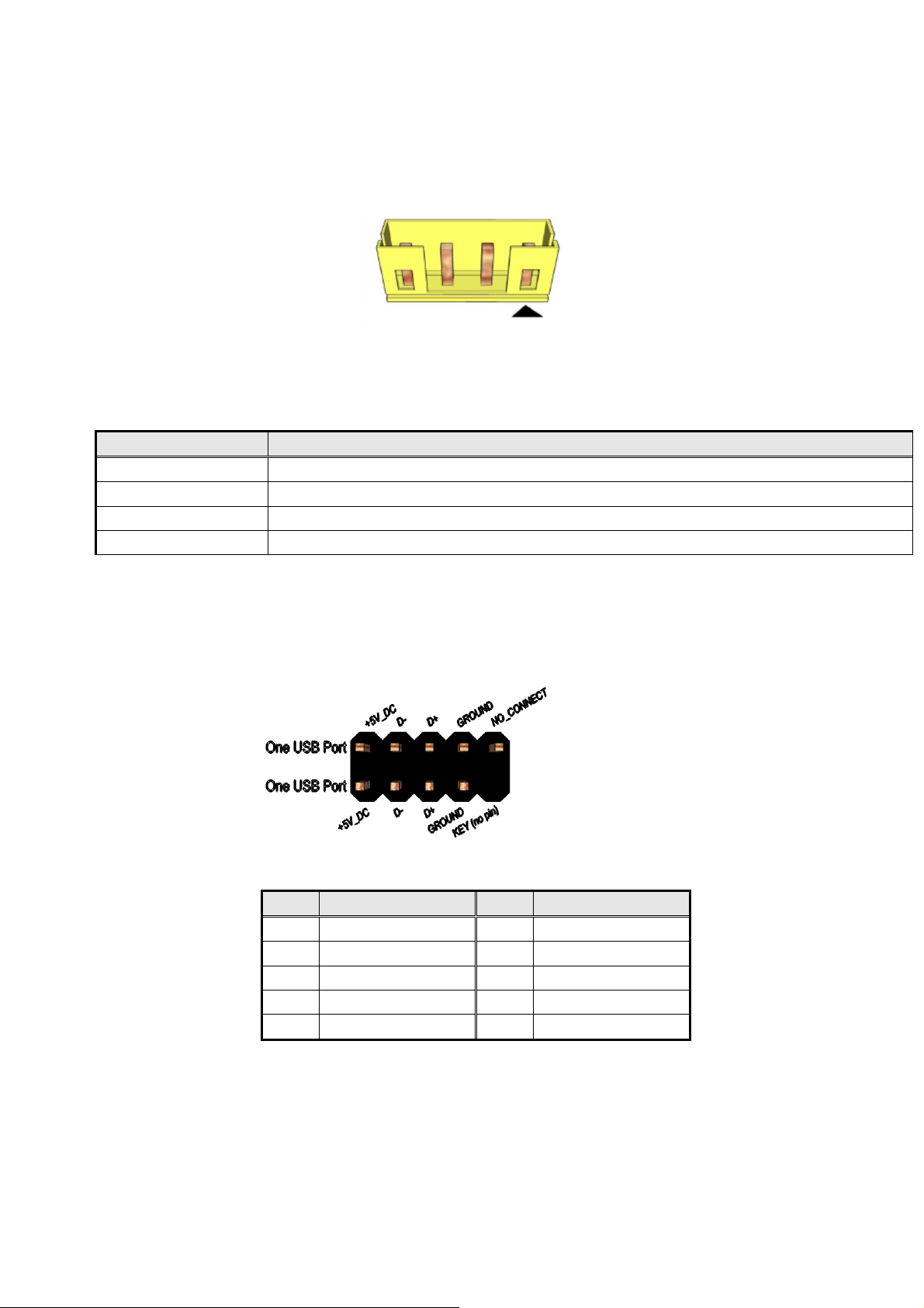
Internal speaker
Figu re 3 Inter n a l s pea ker
Pin Signal Name
1
2
3
4
Front_LFront_L+
Front_R+
Front_R-
T
AB L E 3 INT E R N AL HE A DER S I G NALS
TP & Card reader USB
Figure 4 TP & C ar d r e a der U S B pi n - o u t
Pin Signal Pin Signal
1 5V_USB 2 5V_USB
3 Data (negative) 4 Data (negative)
5 Data (positive) 6 Data (positive)
7 Ground 8 Ground
9 Key (no pin) 10 No Connect
T
AB L E 4 TP & CAR D R E ADE R
USB
S I G N ALS
8
Page 9
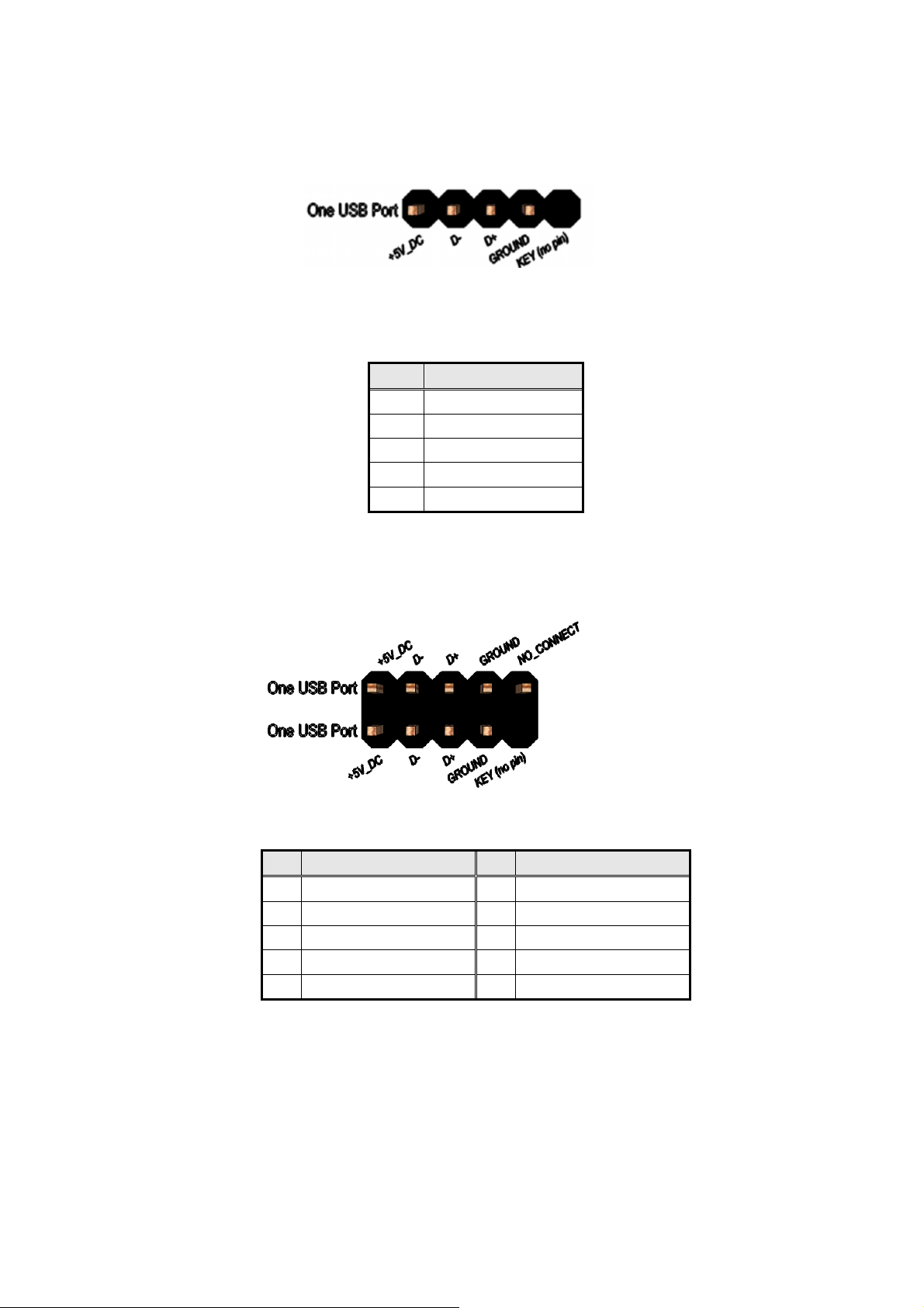
WebCAM header
Figure 5 Web C A M he a der p i n- o u t
Pin Signal name
VCC
1
2
3
4
5
T
AB L E 5 WEB
Data (negative)
Data (positive)
Ground
Key (no pin)
CAM
H E A DER S I G NALS
Side IO USB header
Figure 6 Side IO U S B h ea d e r pin-ou t
Signal Pin Signal
Pin
1 5V_USB 2 5V_USB
3 Data (negative) 4 Data (negative)
5 Data (positive) 6 Data (positive)
7 Ground 8 Ground
9 Key (no pin) 10 No Connect
T
AB L E 6 SID E IO
USB
H E A DER SIG NALS
9
Page 10
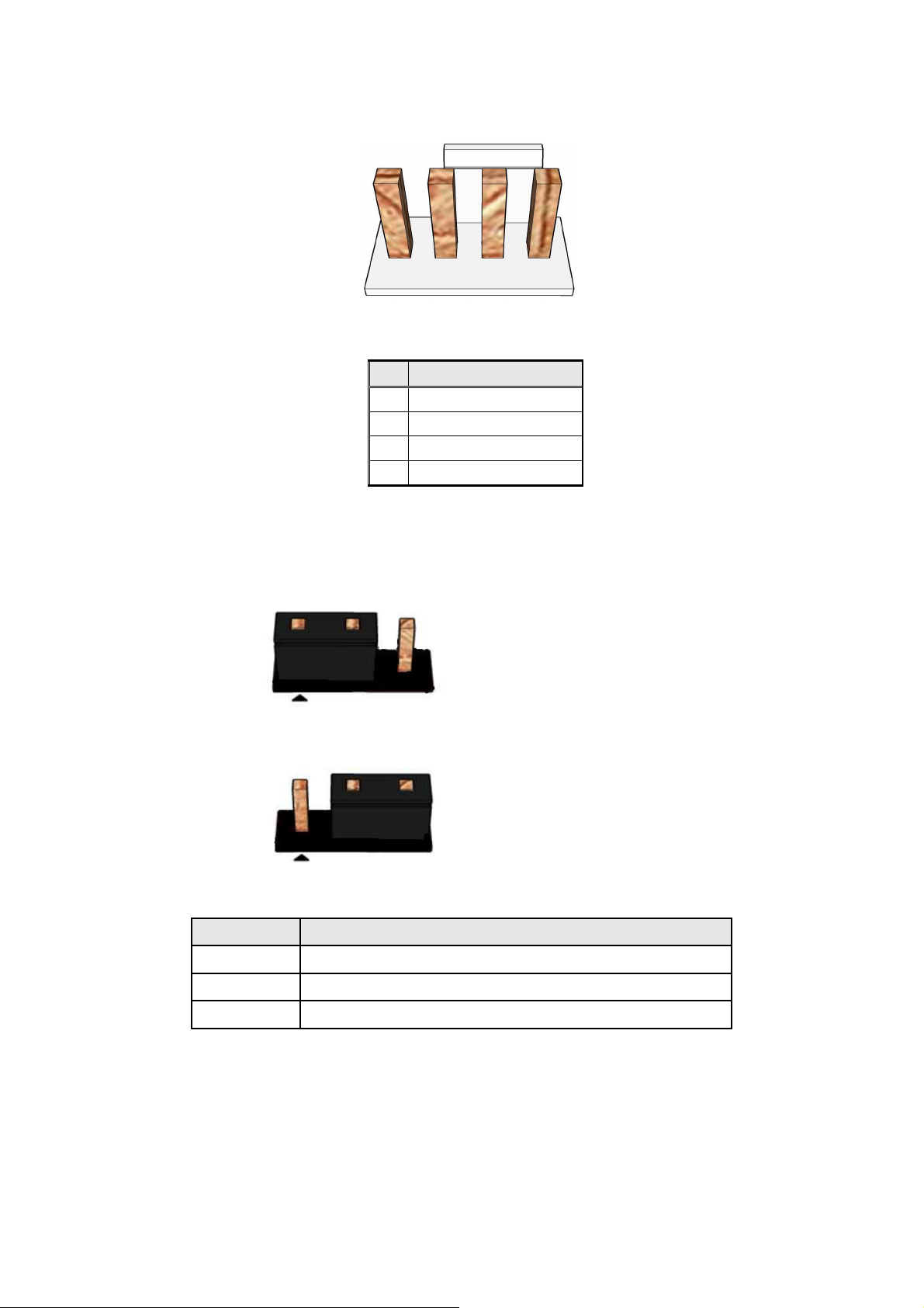
Processor fan header
Figure 7 Process o r f a n h ea d e r pi n- ou t
Pin Signal
1 Ground
2 +12V
3 CPU_FAN_TACH
4 CPU_FAN_CTRL
T
AB L E 7 PROC E S S OR F A N HEAD E R
Inverter power voltage selection header
Pins 1&2: jumper position for 12V
Pins 2&3: jumper position for 19V
Fi g u re 8 I n v e rt er pow e r voltage s e l ec t i on
Pin Signal Name
1 12VDUAL_HDMI
2 BKLT_PWR
3 +19V_A
T
AB L E 8 INV E R TER P O W ER V OLTAGE SELECT I ON H E A DER
10
Page 11
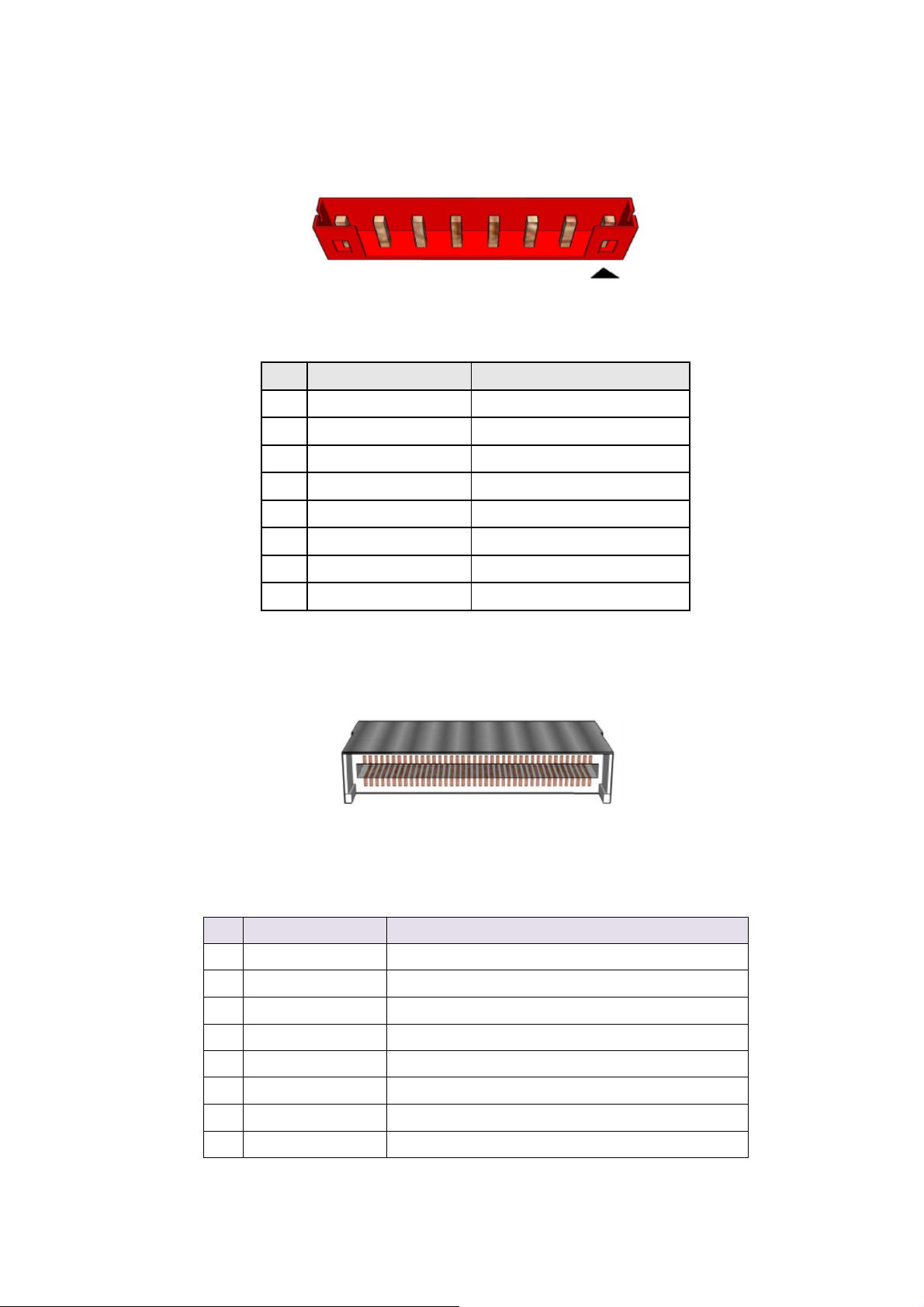
LVDS inverter power header
Fi g u re 9 L VD S i n v e r t e r p ow e r he a der
Pin Signal Name Description
1 LVDS_BKTEN_R Backlight enable
2 LVDS_PWM Backlight PWM control
3 12V/19V Inverter power
4 12V/19V Inverter power
5 GND Ground
6 GND Ground
7 BRIGHT_UP- BRIGHTNESS UP
8 BRIGHT_DOWN- BRIGHTNESS DOWN
T
AB L E 9 8-PI N
LVDS data header
Pin Signal Description
1 TD0P LVDS Channel A diff data output - positive
2 TD0N LVDS Channel A diff data output - negative
LVDS
I N V ERTE R P OWER H E ADER PIN-OUT R EFERE N C E
Fi gur e 1 0 : P r oc es s or fan h e a der
3 TC0P LVDS Channel A diff data output - positive
4 TC0N LVDS Channel A diff data output - negative
5 TB0P LVDS Channel A diff data output - positive
6 TB0N LVDS Channel A diff data output - negative
7 TA0P LVDS Channel A diff data output - positive
8 TA0N LVDS Channel A diff data output - negative
11
Page 12

9 TD1P LVDS Channel B diff data output-positive
10 TD1N LVDS Channel B diff data output-negative
11 TC1P LVDS Channel B diff data output-positive
12 TC1N LVDS Channel B diff data output-negative
13 TB1P LVDS Channel B diff data output-positive
14 TB1N LVDS Channel B diff data output-negative
15 TA1P LVDS Channel B diff data output-positive
16 TA1N LVDS Channel B diff data output-negative
17 GND Ground
18 3.3V/5V/12V Selectable LCD power output
19 3.3V/5V/12V Selectable LCD power output
20 3.3V/5V/12V Selectable LCD power output
21 NC NC
22 EDID_3.3V VCC3
23 GND Ground
24 GND Ground
25 GND Ground
26 TCK0P LVDS Channel A diff data output - positive
27 TCK0N LVDS Channel A diff data output - negative
28 GND Ground
29 GND Ground
30 GND Ground
31 NC NC
32 BKLT_EN
33 LVDS_PWM
34 TCK1P LVDS Channel B diff data output - positive
35 TCK1N LVDS Channel B diff data output - negative
36 BKLT_PWR Selectable BKLT power output
37 BKLT_PWR Selectable BKLT power output
38 BKLT_PWR Selectable BKLT power output
39 NC NC
40 NC NC
T
AB L E
10: 40-
PI N
LVDS
D A T A HEAD E R PIN-OU T REFE R E NCE
12
Page 13

CMOS Clear Header
DMIC Header
Pin Signal Name Description
1 VCC Power
2 DMIC_DATA_R DMIC DATA
3 Ground Ground
4 DMIC_CLK_R DMIC CLOCK
5 KEY NO pin
Figu re 1 1
T
AB L E 11
Fi gur e 1 2
T
AB L E 12
CMOS Clear Header
CMOS Clear
1-2 Clear CMOS
2-3 Normal
CMOS C
DMIC Cable pin-out
DMIC C
LEAR BEHAVIOR
ABLE SIGNALS
13
Page 14
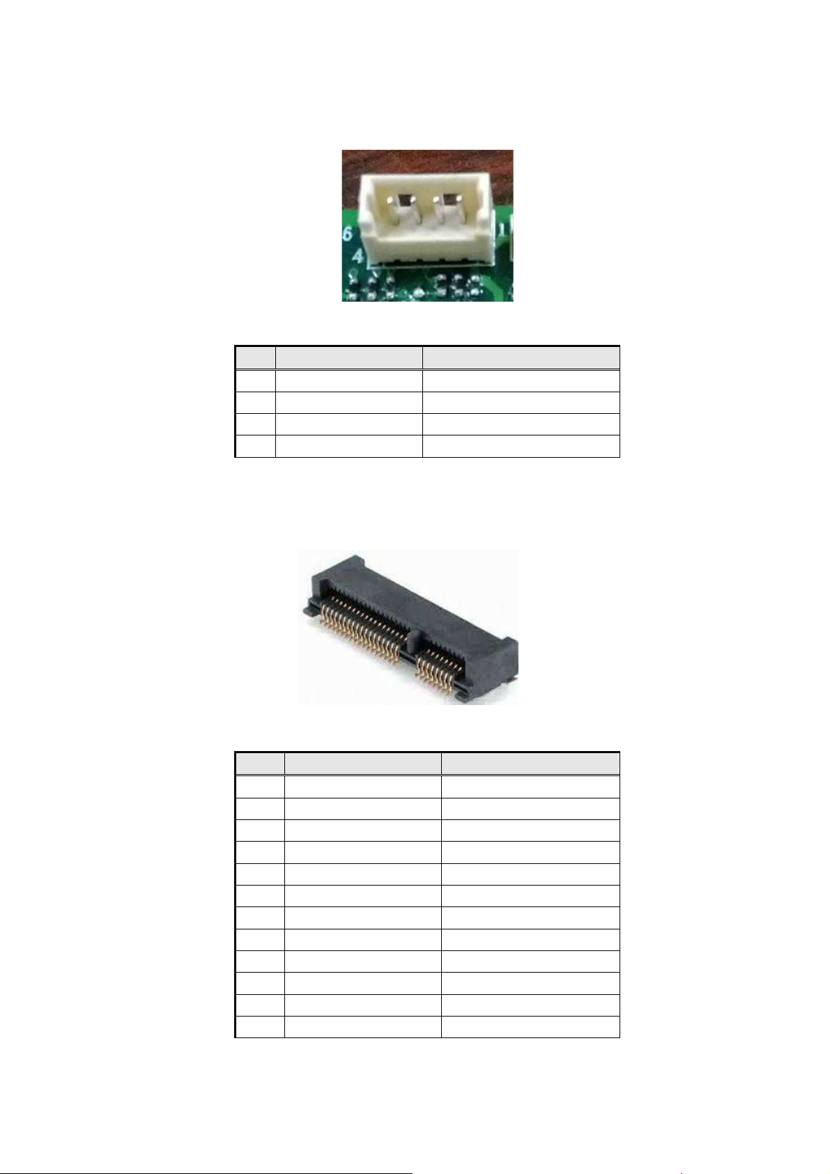
Ambient Light Sensor header
Fi gur e 1 3
Pin Signal Name Description
1 VCC3_HDMI Power
2 Ground Ground
3 Sensor_CLK Front SW/LEDs CLOCK
4 Sensor_DATA Front SW/LEDs DATA
T
AB L E 13
Ambient Light Sensor header pin-out
A
MBIENT LIGHT SENSOR CABLE SIGNALS
MiniPCIe slot
Fi gur e 1 4
Pin Signal Name Description
1 WAKE- Wake up
2 3VSB Power
3 NC NC
4 Ground Ground
5 NC NC
6 V_1P5 Power
7 CLKREQ_WLAN- CLKREQ
8 NC NC
9 Ground Ground
10 NC NC
11 PCH_100M_WIRELESS- CLOCK(negative)
12 NC NC
MiniPCIe slot For WLAN pin-out
14
Page 15

13 PCH_100M_WIRELESS CLOCK(positive)
14 NC NC
15 Ground Ground
16 NC NC
17 NC NC
18 Ground Ground
19 NC NC
20 WLAN_DISABLE- DAC output
21 Ground Ground
22 PCIE_RST- Reset
23 PCIe_WIRELESS_RX- Receive(negative)
24 3VSB Power
25 PCIe_WIRELESS_RX+ Receive(positive)
26 Ground Ground
27 Ground Ground
28 V_1P5 Power
29 Ground Ground
30 SMB_CLK_RESUME SMbus CLOCK
31 PCIe_WIRELESS_TX- Transmit(negative)
32 SMB_DATA_RESUME SMbus DATA
33 PCIe_WIRELESS_TX+ Transmit(positive)
34 Ground Ground
35 Ground Ground
36 USB_PCH_DN10 DATA(negative)
37 Ground Ground
38 USB_PCH_DP10 DATA(Positive)
39 3VSB Power
40 Ground Ground
41 3VSB Power
42 NC NC
43 Ground Ground
44 3VSB Power
45 NC NC
46 NC NC
47 NC NC
48 V_1P5 Power
49 NC NC
50 Ground Ground
51 NC NC
52 3VSB Power
GND1 Ground Ground
GND2 Ground Ground
T
AB L E 14
M
INI
PCI
E SLOT FOR
WLAN
SIGNALS
15
Page 16
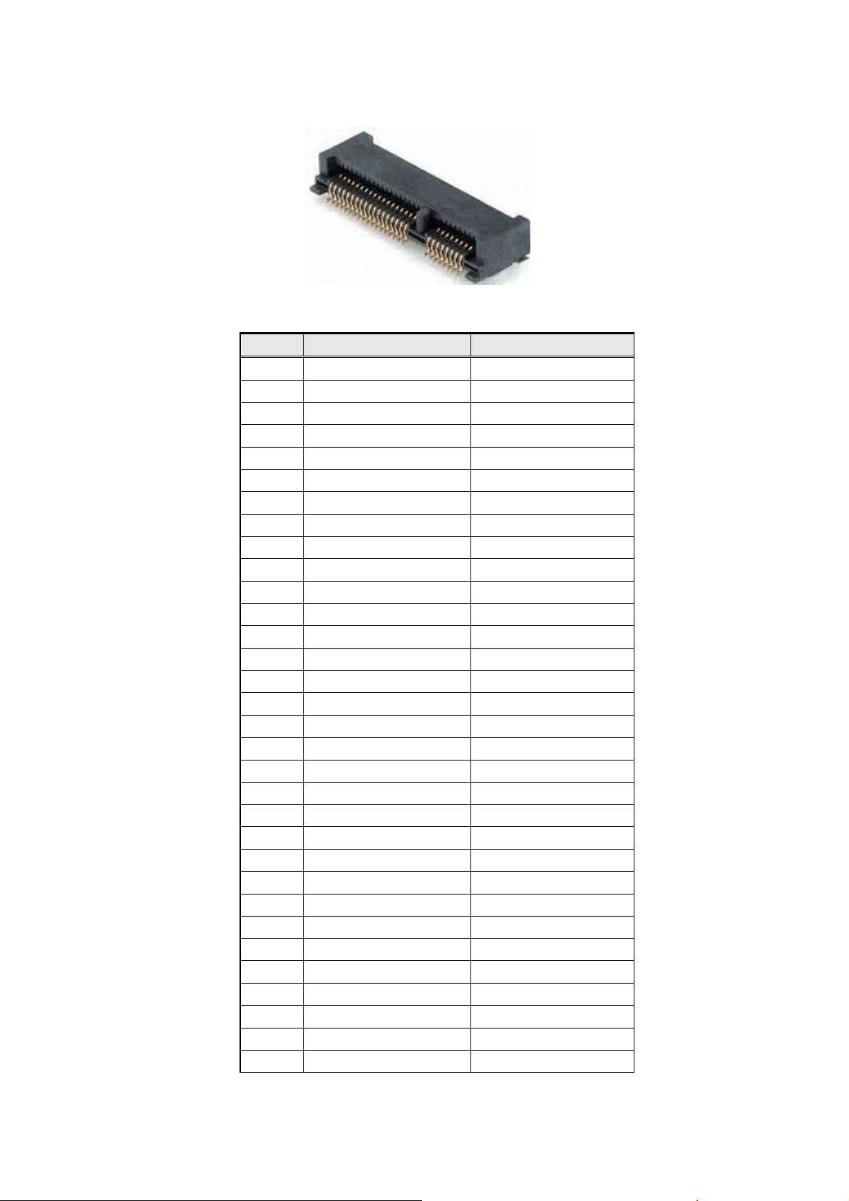
MiniPCIe slot
Figure 15
Pin Signal Name Description
1 NC NC
2 3VSB Power
3 NC NC
4 Ground Ground
5 NC NC
6 V_1P5 Power
7 CLKREQ_TV- CLKREQ
8 NC NC
9 Ground Ground
10 NC NC
11 PCH_100M_TVBD- CLOCK(negative)
12 NC NC
13 PCH_100M_TVBD CLOCK(positive)
14 NC NC
15 Ground Ground
16 NC NC
17 NC NC
18 Ground Ground
19 NC NC
20 NC NC
21 Ground Ground
22 PCIE_RST- Reset
23 PCIe_TVBD_RX-_R Receive(negative)
24 3VSB Power
25 PCIe_TVBD_RX+_R Receive(positive)
26 Ground Ground
27 Ground Ground
28 V_1P5 Power
29 Ground Ground
30 SMB_CLK_MAIN SMbus CLOCK
31 PCIe_TVBD_TX-_R Transmit(negative)
32 SMB_DATA_MAIN SMbus DATA
MiniPCIe slot For SSD/TV card pin-out
16
Page 17
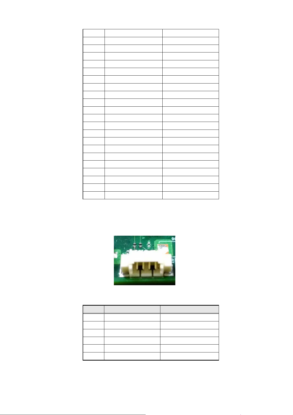
33 PCIe_TVBD_TX+_R Transmit(positive)
34 Ground Ground
35 Ground Ground
36 USB_PCH_DN9 DATA(negative)
37 Ground Ground
38 USB_PCH_DP9 DATA(Positive)
39 3VSB Power
40 Ground Ground
41 3VSB Power
42 NC NC
43 Ground Ground
44 3VSB Power
45 NC NC
46 NC NC
47 NC NC
48 V_1P5 Power
49 NC NC
50 Ground Ground
51 NC NC
52 3VSB Power
GND1 Ground Ground
GND2 Ground Ground
T
AB L E 15
M
INI
PCI
E SLOT FOR
SSD/TV
CARD SIGNALS
NFC/RFID header pin-out
Figu re 1 6
Pin Signal Name Description
1 Ground Ground
2 VCC Power
3 UART0_TXD UART Transmit
4 UART0_RXD UART Receive
GND1 Ground Ground
GND2 Ground Ground
T
AB L E 16
NFC/RFID header pin-out
NFC/RFID
S I G NALS
17
Page 18
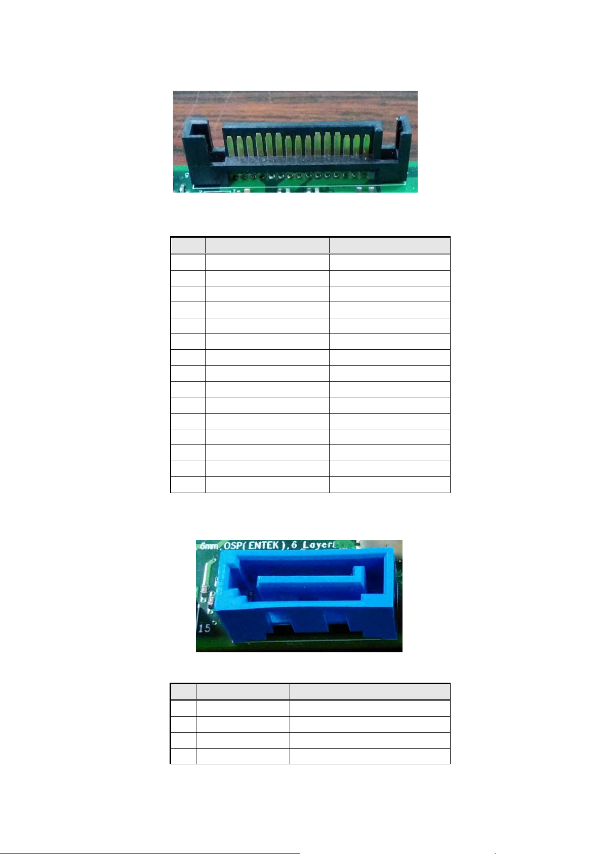
SATA Power
Fi g u re 1 7
Pin Signal Name Description
1 VCC3 Power
2 VCC3 Power
3 VCC3 Power
4 GND Ground
5 GND Ground
6 GND Ground
7 VCC Power
8 VCC Power
9 VCC Power
10 GND Ground
11 RES NC
12 GND Ground
13 +12V Power
14 +12V Power
15 +12V Power
T
AB L E 17
SATA Power Cable pin-out
SATA P
OW E R CAB L E SI G N A LS
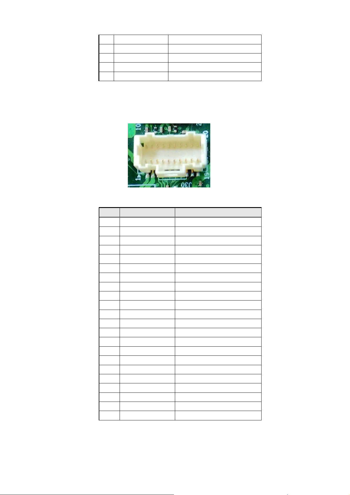
SATA ODD
Figure 18
Pin Signal Name Description
1 GND Ground
2 SATAHDR_TXP0_C SATA DATA Transmit(positive)
3 SATAHDR_TXN0_C SATA DATA Transmit(negative)
4 GND Ground
ODD Cable pin-out
18
Page 19
5 SATAHDR_RXN0_C SATA DATA Receive(negative)
6 SATAHDR_RXP0_C SATA DATA Receive(positive)
7 GND Ground
8 G1 NC
9 G2 NC
T
AB L E 18
ODD C
AB L E SIGN A LS
Front SW/LEDs
Figure 19
Pin Signal Name Description
1 VCC Power
2 V_5P0_REG Power
3 VCC3 Power
4 PWRBT_N Power button
5 GRN_BLNK_HRD Indicator light (Green)
6 HDMIBT_N HDMI button
7 YLW_BLNK_HRD Indicator light (Yellow)
8 Sensor_CLK Front SW/LEDs CLOCK
9 SATA_LED- Hard disk activity LED
10 Sensor_DATA Front SW/LEDs DATA
11 NIGHT_MODE Night mode
12 HDMI_ON HDMI Condition : ON
13 CM3633_INT- UART Transmit
14 ECOBT_N ECO button
15 ECO_LED ECO Indicator light
16 Ground Ground
17 ECO_ON ECO Condition : ON
18 Ground Ground
19 VCC power
20 Ground Ground
GND1 Ground Ground
GND2 Ground Ground
T
AB L E 19 FRO N T
Front SW/LEDs Y Cable pin-out
SW/LEDS Y C
AB L E SIGNA L S
19
Page 20
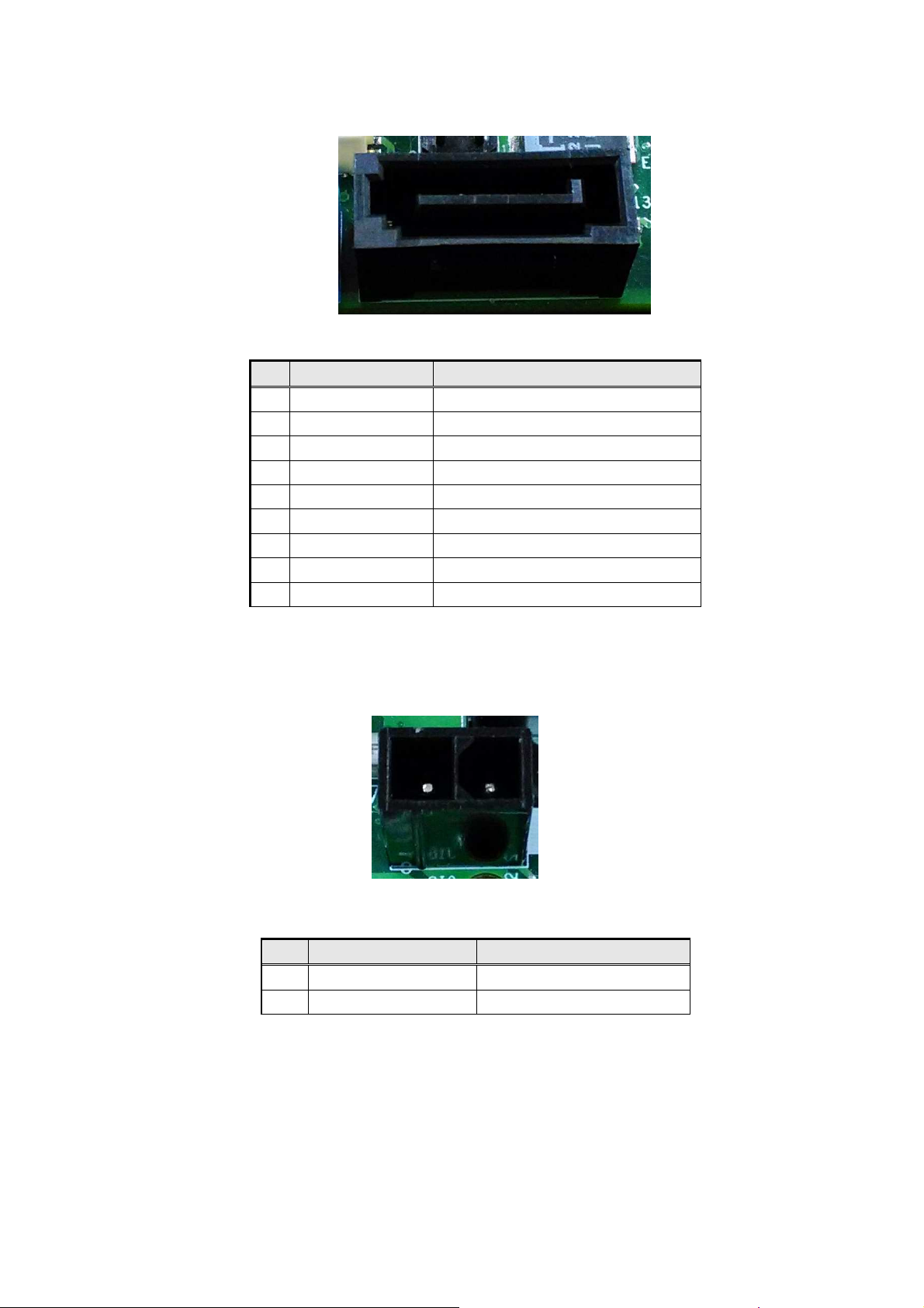
SATA HDD
Figu re 2 0 H D D Ca b l e pin-out
Pin Signal Name Description
1 GND Ground
2 SATAHDR_TXP1_C SATA DATA Transmit(positive)
3 SATAHDR_TXN1_C SATA DATA Transmit(negative)
4 GND Ground
5 SATAHDR_RXN1_C SATA DATA Receive(negative)
6 SATAHDR_RXP1_C SATA DATA Receive(positive)
7 GND Ground
8 G1 NC
9 G2 NC
T
AB L E 20
HDD C
AB L E SIGN A LS
Wireless Charger Header
Figu re 2 1 Wir e l e s s C ha rgi n g M o dul e pin-out
Pin Signal Name Description
1 GND Ground
2 +19V_charge Charge Power
T
AB L E 20
W
IRELESS CHARGING MODULE SIGNALS
20
Page 21

MITAC Desktop Board PH11SI
BIOS Specifiction
21
Page 22
Main
Advanced
Chipset
Security
Boot
Save & Exit
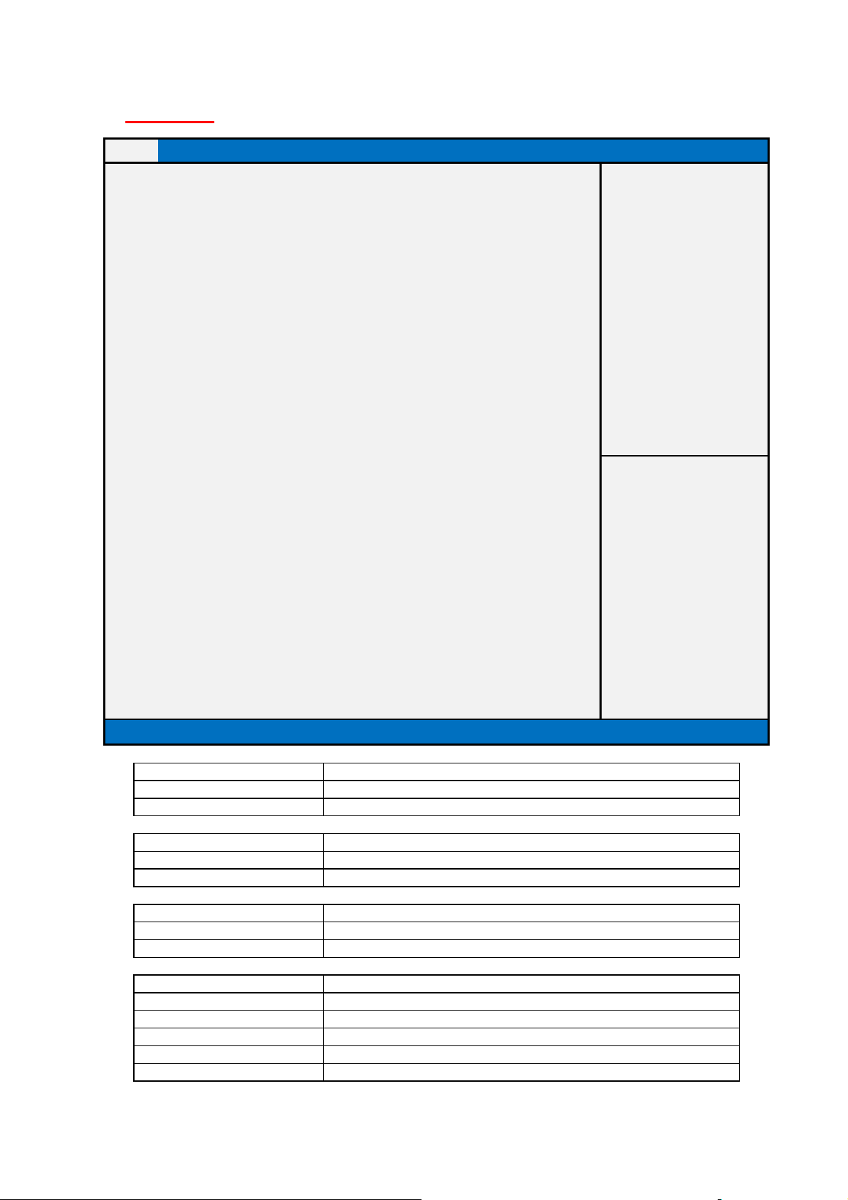
BIOS Information
Item help
BIOS Vender
Ameri
can Megatrends
Core Version
5.11
Compliancy
UEFI 2.4 ; PI 1.3
BIOS Version
D7520
A01
Build Date
05/25/2015
EC Version
04A
Processor Information
Intel(R) CORE(TM) i5
-
6400 CPU @ 2.70GHZ
Memory Information
Total Memory
8192 MB (DDR3 1333)
Memory Frequency
2133 MHz
System Date
[Fri mm/dd/yyyy]
System Time
[hh:mm:ss]
Field Name
Default Value
AMI Megatrends
Comment
This field is not selectable. There i
s no help text associated with it.
Default Value
5.011
Comment
This field is not selectable. There is no help text associated with it.
Field Name
Field Name
Default Value
Display the version of the BIOS
Comment
This field is not selectable. There is no help text associated with it.
Comment
This field is not selectable. There is no help text associated with it.
Main Page
→←: Select Screen
↑↓: Select Item
Enter: Select
+/- : Change Opt
F1: General Help
F2: Previous Values
F3: Optimized Defaults
F4: Save & Reset
ESC: Exit
Version 2.17.1249. Copyright (C) 2015 American Megatrends, Inc.
BIOS Vender
Field Name Core Version
Compliancy
Default Value UEFI 2.4 ; PI 1.3
Comment This field is not selectable. There is no help text associated with it.
BIOS Version
Field Name Build Date
Default Value Display build time of the BIOS
22
Page 23

Field Name
Default Value
Display the version of the BIOS
Comment
This field is not selectable. There is no help text associated with it.
Value
Display the installed CPU brand.
Comment
This field is not selectable. There is no help text associated with it.
Field Name
Field Name
Value
Display the installed memory
frequency
.
Comment
This field is not selectable. There is no help text associated with it.
Default Value
[xxx, mm
dd
yyyy]
P
ossible Value
[xxx, xx:xx:xxxx]
Help Set the Date. Use Tab to switch between Date elements.
EC Version
Field Name Processor Information
Total Memory
Value Display the installed memory size.
Comment This field is not selectable. There is no help text associated with it.
Memory Frequency
Field Name System Date
Field Name System Time
Default Value [hh :mm :ss]
Possible Value [xx :xx :xx]
Help Set the Time. Use Tab to switch between Time elements.
23
Page 24
Field Name
Default Value
[Enabled]
Field Name
Default Value
[Enabled]
DeepSx Power Policies Enabled in S4
-
S5 )
00:22:4D:B5:ED:D4)
Possible Value
Enabled
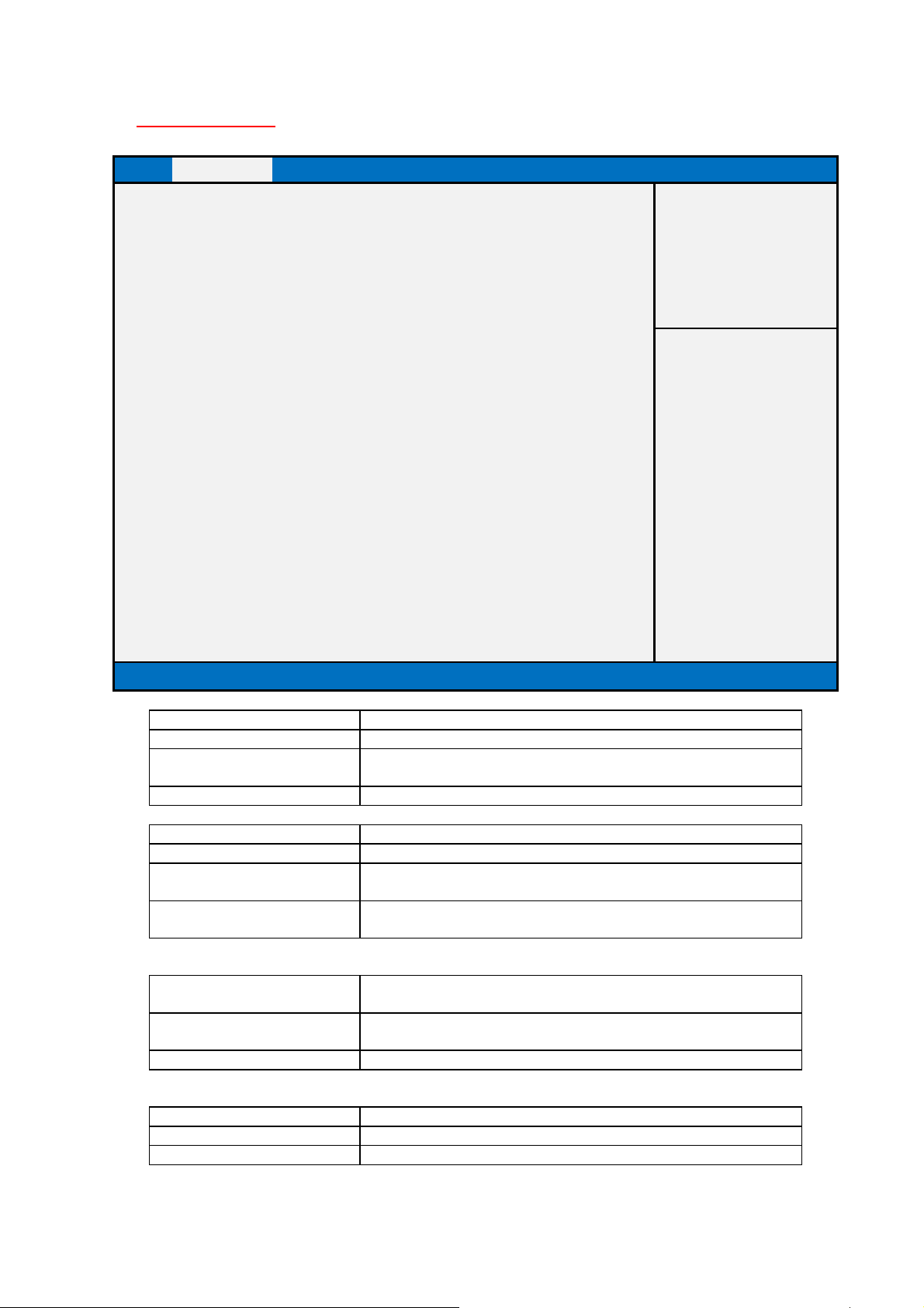
Advanced Page
Main Advanced Chipset Security Boot Save & Exit
Wireless RF [Enabled]
Item help
Wake on Lan [Enabled]
RealTek LAN Controller [Enabled]
►RealTek PCIe GBE Family Controller
(MAC:00:22:4D:B5:ED:D4)
►ACPI Settings
►Fan Speed Configuration
►SMART Settings
►S5 RTC Wake Settings
►CPU Configuration
►SATA Configuration
►AMI Graphic Output Protocol Policy
►Network Stack Configuration
►CSM Configuration
►USB Configuration
Version 2.17.1249. Copyright (C) 2015 American Megatrends, Inc.
Wireless RF
→←: Select Screen
↑↓: Select Item
Enter:Select
+/- : Change Opt
F1: General Help
F2: Previous Values
F3: Optimized Defaults
F4: Save & Reset
ESC: Exit
Possible Value Enabled
Disabled
Help Enable or Disable Wireless RF switch.
Wake On Lan
Possible Value Enabled
Disabled
Help Enable or Disable Wake On Lan. (The item will be hided when set
Field Name RealTek PCIe GBE Family Controller (MAC:
Help Get driver information and configure Realtek Ethernet controller
parameter.
Comment Press Enter when selected to go into the associated Sub-Menu.
Field Name LAN Controller
Default Value [Enabled]
24
Page 25

Help Enable or Disable
onboard NIC.
Field Name
Help System SMART Settings.
Help Enable system to wake from S5 using RTC alarm
Comment
Press Enter when selected to go into the associated Sub
-
Menu.
Field Name
Help SATA Devices Options Settings.
Help User Select Monitor Output by Graphic Output Protocol
CSM configuration: Enable/Disable, Option Rom execution setting, etc.
Field Name
Help USB Configuration Parameters.
Disabled
Field Name ACPI Settings
Help System ACPI Parameters.
Comment Press Enter when selected to go into the associated Sub-Menu.
Field Name Fan Speed Configuration
Help Fan Control Configuration.
Comment Press Enter when selected to go into the associated Sub-Menu.
SMART Settings
Comment Press Enter when selected to go into the associated Sub-Menu.
Field Name S5 RTC Wake Settings
Field Name CPU Configuration
Help CPU Configuration Parameters
Comment Press Enter when selected to go into the associated Sub-Menu.
SATA Configuration
Comment Press Enter when selected to go into the associated Sub-Menu.
Field Name AMI Graphic Output Protocol Policy (Hided if “Launch CSM” =
Enabled)
Comment Press Enter when selected to go into the associated Sub-Menu.
Field Name Network Stack Configuration
Help Network Stack Settings.
Comment Press Enter when selected to go into the associated Sub-Menu.
Field Name CSM Configuration
Help
Comment Press Enter when selected to go into the associated Sub-Menu.
USB Configuration
Comment Press Enter when selected to go into the associated Sub-Menu.
25
Page 26
Driver Name:
PCI Slot:
MAC Address:
Realtek PCIe GBE Family Controller (MAC:00:22:4d:AF:ED:D4)
Main Advanced Chipset Boot Security Save & Exit
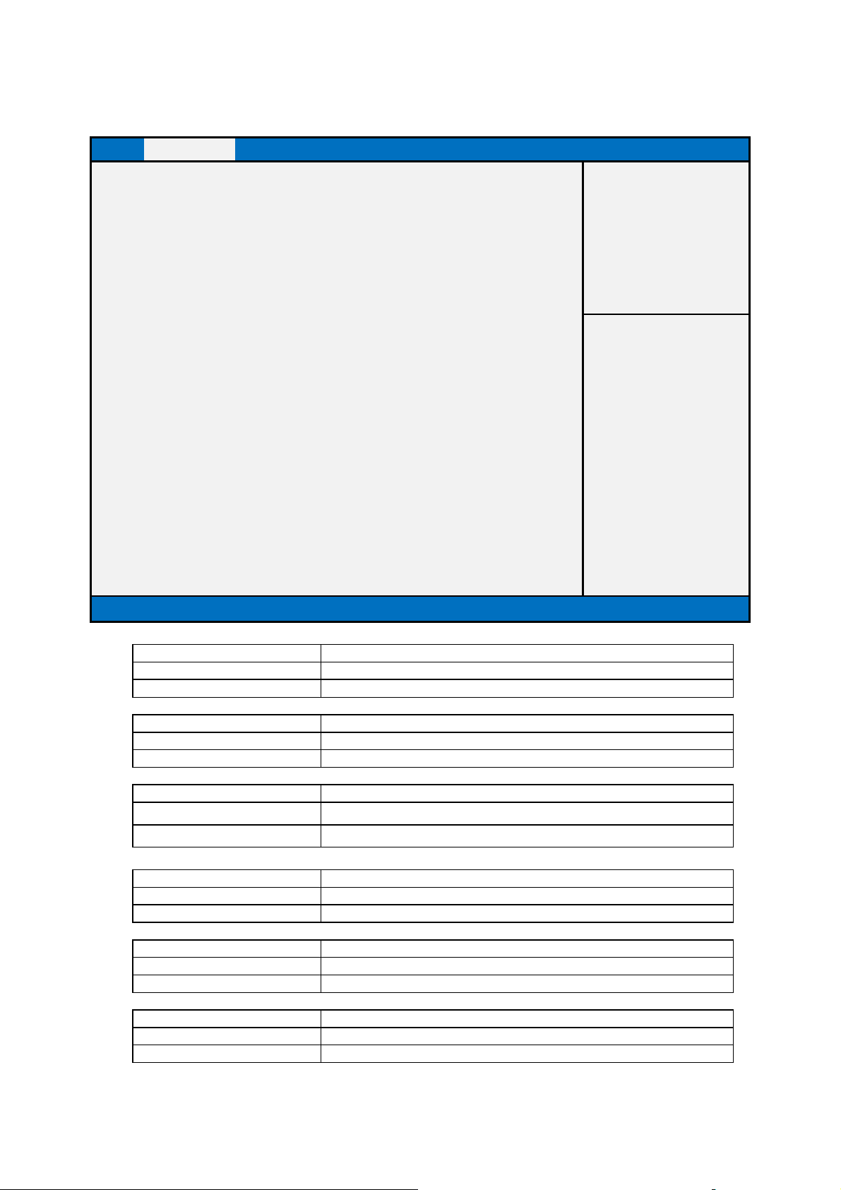
Driver Information
Item help
Driver Name: Realtek UEFI UNDI Driver
Driver Version 2.035
Driver Release Date: 2015/03/30
Device Information
Device Name: Realtek PCIe GBE Family
PCI Slot: 01:00:00
MAC Address: 00:22:4D:B5:FA:DB
Patent Information
This product is covered by one or
More of the following patents:
US6,570,884, US6,115,776 and
US6,327,625
Version 2.14.1219. Copyright (C) 2011 American Megatrends, Inc.
→←: Select Screen
↑↓: Select Item
Enter: Select
+/- : Change Opt
F1: General Help
F2: Previous Values
F3: Optimized Defaults
F4: Save & Reset
ESC: Exit
Field Name
Default Value Installed UEFI Driver Name
Comment This field is not selectable. There is no help text associated with it.
Field Name Driver Version:
Default Value Installed UEFI Driver Version
Comment This field is not selectable. There is no help text associated with it.
Field Name Driver Release Date:
Default Value Installed UEFI Driver Release Date
Comment This field is not selectable. There is no help text associated with it.
Field Name Device Name:
Default Value UEFI driver support device
Comment This field is not selectable. There is no help text associated with it.
Field Name
Default Value Device PCI Bus/Device/Number
Comment This field is not selectable. There is no help text associated with it.
Field Name
Default Value LAN Device Mac address
Comment This field is not selectable. There is no help text associated with it.
26
Page 27
Main
Advanced
Chipset
Security
Boot
Save & Exit
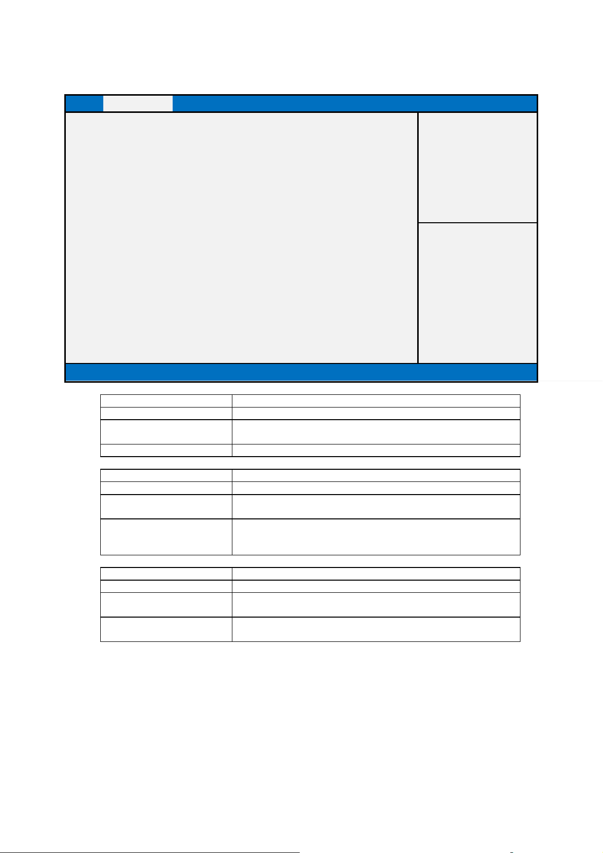
ACPI Settings
Item help
Enable ACPI Auto Configuration
[Disabled]
Enable Hibernation
[Enabled]
ACPI Sleep State
[S3 (Suspend to R
AM)]
Fi
eld Name
Disabled
Help Enables or Disables BIOS ACPI Auto Configuration.
Disabled
WindowsXP.
Field Name
S3 (Suspend to RAM)
ACPI Settings
→←: Select Screen
↑↓: Select Item
Enter: Select
+/- : Change Opt
F1: General Help
F2: Previous Values
F3: Optimized Defaults
F4: Save & Reset
ESC: Exit
Version 2.17.1249. Copyright (C) 2015 American Megatrends, Inc.
Default Value [Disabled]
Possible Value Enabled
Field Name Enable Hibernation
Default Value [Enabled]
Possible Value Enabled
Help Enables or Disables System ability to Hibernate (OS/S4 Sleep State).
Default Value [Both S1 and S3 available for OS to choose from]
Possible Value Suspend Disabled
Help Select the highest ACPI sleep state the system will enter when the
Enable ACPI Auto Configuration
This option may be not effective with some OS. For example,
ACPI Sleep State
SUSPEND button is pressed.
27
Page 28
Default Value
[Auto]
Possible Value
Auto / Manual
Field Name
Default Value
[Normal]
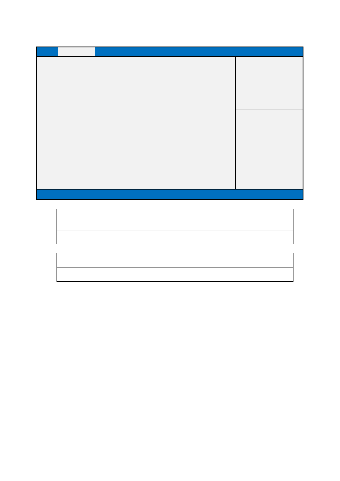
Fan Speed Configuration
Main Advanced Chipset Security Boot Save & Exit
Fan Speed Configuration
Item help
Fan Speed Control [Auto]
CPU Fan Speed [Normal]
Version 2.17.1249. Copyright (C) 2015 American Megatrends, Inc.
Field Name Fan Speed Control
Help Set Fan Speed mode. Attention: Select Manual Silent or Normal mode
may be NOT cooling system enough.
CPU Fan Speed
→←: Select Screen
↑↓: Select Item
Enter: Select
+/- : Change Opt
F1: General Help
F2: Previous Values
F3: Optimized Defaults
F4: Save & Reset
ESC: Exit
Possible Value Silent / Normal / Optimize
Help Adjust CPU Fan Speed PWM Duty.
28
Page 29
Main
Advanced
Chipset
Security
Boot
Save & Exit
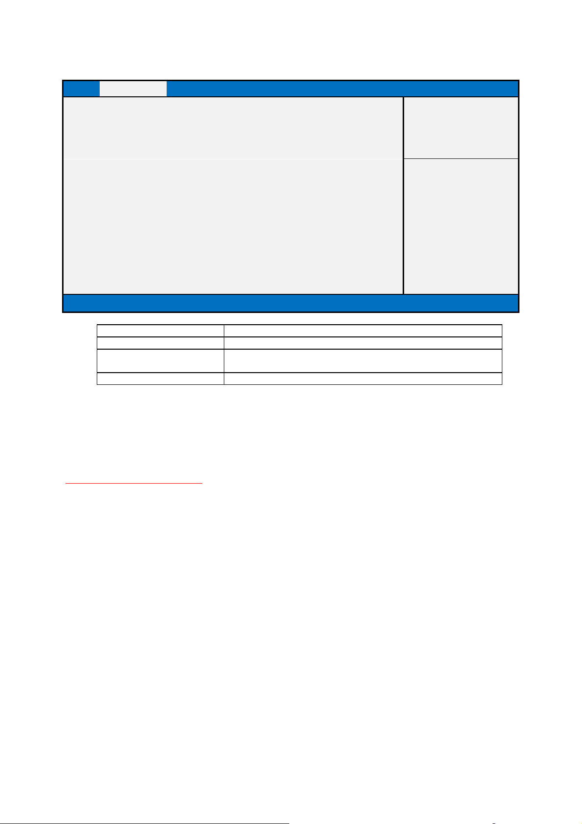
SMART Settings
Item help
SMART Self Test
[Disabled]
Enabled
Help Run SMART Self Test on all HDDs during POST.
SMART Settings
→←: Select Screen
↑↓: Select Item
Enter: Select
+/- : Change Opt
F1: General Help
F2: Previous Values
F3: Optimized Defaults
F4: Save & Reset
ESC: Exit
Version 2.17.1249. Copyright (C) 2015 American Megatrends, Inc.
Field Name SMART Self Test
Default Value [Disabled]
Possible Value Disabled
29
Page 30
Field
Name
Disabled
Field Name
Default Value
0
Possible Value
0-23
Field Name
Default Value
0
Possible Value
0-59
Field Name
Default Value
0
Possible Value
0 - 59
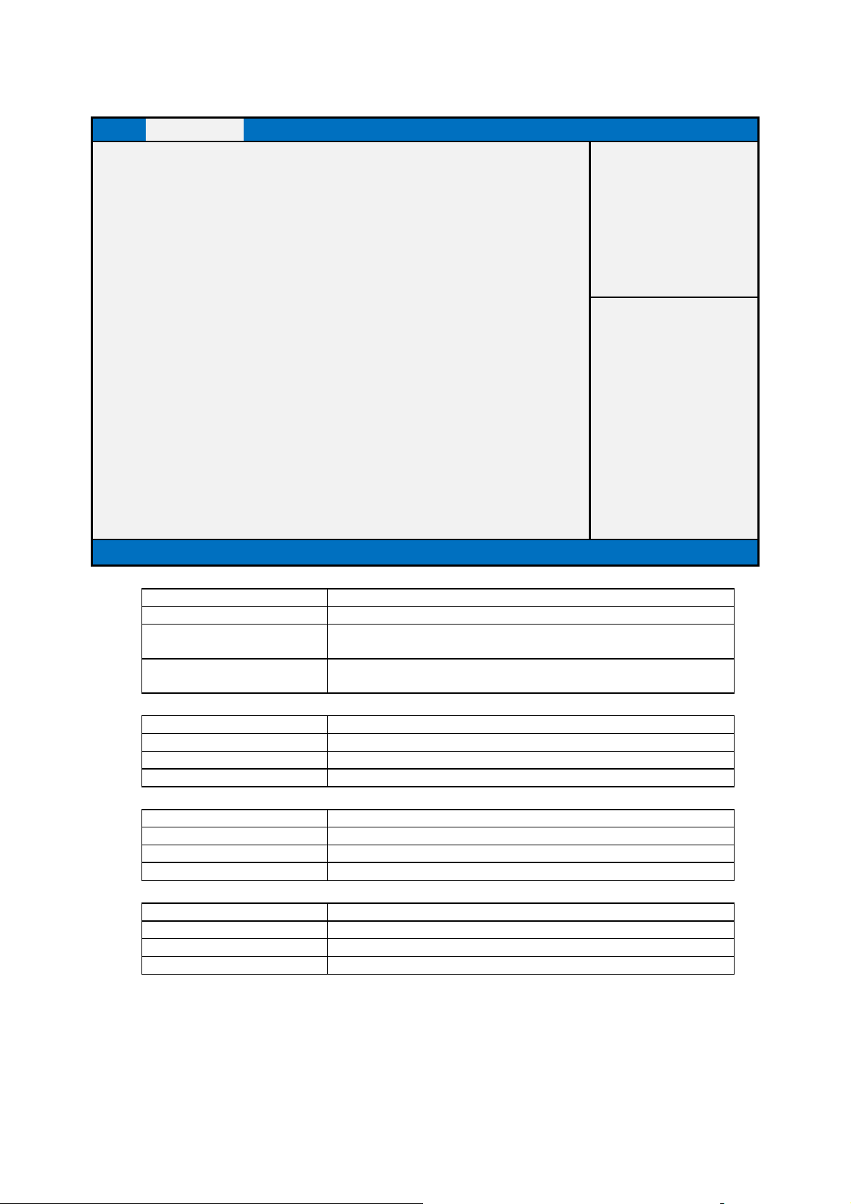
S5 RTC Wake Settings
Main Advanced Chipset Security Boot Save & Exit
Wake system with Fixed Time [Disabled]
Item help
Wake up hour 0
Wake up minute 0
Wake up second 0
Version 2.17.1249. Copyright (C) 2015 American Megatrends, Inc.
→←: Select Screen
↑↓: Select Item
Enter: Select
+/- : Change Opt
F1: General Help
F2: Previous Values
F3: Optimized Defaults
F4: Save & Reset
ESC: Exit
Wake system with Fixed Time
Default Value [Disabled]
Possible Value Fixed Time
Help Enable or Disable System wake on alarm event. System will wake on
the hr::min::sec specified. For Win8.1, disable fast startup.
Wake up hour
Help Select 0-23 For example enter 3 for 3am and 15 for 3pm
Wake up minute
Help 0 - 59
Wake up second
Help 0 - 59
30
Page 31
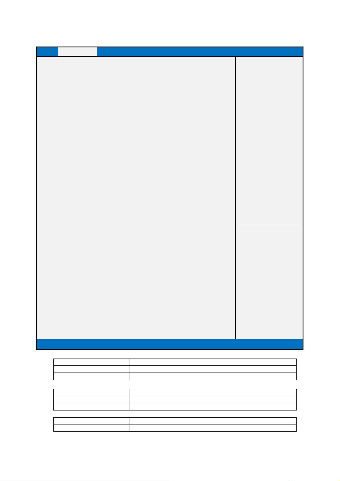
Field Name
Default Value
[Intel CPU Brand String]
Comment
This field is not selectable. There is no help text associated with it.
Default Value
Displays CPU Signature
Comment
This field is not selectable. There is no help text associated with it.
CPU Configuration
Main Advanced Chipset Security Boot Save & Exit
CPU Configuration
Item help
Intel(R) Core(TM) CPU [CPU NAME] @ [CPU Freq.] GHz
CPU Signature 506e3
Microcode Patch Not loaded
Max CPU Speed 2700 MHz
Min CPU Speed 800 MHz
CPU Speed 3100 MHz
Processor Cores 4
Hyper threading Technology Not Supported
Intel VT-x Technology Supported
Intel SMX Technology Not Supported
64-bit Supported
L1 Data Cache 32 KB x 4
L1 Code Cache 32 KB x 4
L2 Cache 256 KB x 4
L3 Cache 6MB
L4 Cache Not Present
Hyper-threading
[Enabled]
Active Processor Cores [All]
Intel Virtualization Technology [Enabled]
Hardware Prefetcher [Enabled]
Adjacent Cache Line Prefetch [Enabled]
Intel(R) SpeedStep(tm) [Enabled]
Turbo Mode [Enabled]
CPU C states [Enabled]
Enhanced C-states [Enabled]
Package C State limit [AUTO]
Intel TXT(LT) Support [Disabled]
Version 2.17.1249. Copyright (C) 2015 American Megatrends, Inc.
→←: Select Screen
↑↓: Select Item
Enter: Select
+/- : Change Opt
F1: General Help
F2: Previous Values
F3: Optimized Defaults
F4: Save & Reset
ESC: Exit
CPU Configuration
Field Name CPU Signature
Field Name Microcode Patch
Default Value CPU Microcode Patch Revision
31
Page 32

Field Name
Field Name
Default Value
Displays the Min CPU Speed
Comment
This field is not selectable. There is no help text associated with it.
Comment
This field is not selectable. There is no help text associated with it.
Field Name
Field Name
Default Value
When Hyper
-
threading is enabled, 2 logical CPUS per core is present.
Comment
This field is not selectable. There is no help text associated with it.
Comment
This field is not selectable. There is no help text associated with it.
Field Na
me
Field Name
Default Value
Displays if 64
-
bit supported
Comment
This field is not selectable. T
here is no help text associated with it.
Disabled
Threading
Threading Technology). When Disable only one thread per enabled
Default Value
[All]
Field Name
Default Value
[Enabled]
provided by Vanderpool Technology
Comment This field is not selectable. There is no help text associated with it.
Max CPU Speed
Default Value Displays the Max CPU Speed
Comment This field is not selectable. There is no help text associated with it.
Min CPU Speed
Field Name CPU Speed
Default Value Displays the CPU Speed
Processor Cores
Default Value Displays number of cores.
Comment This field is not selectable. There is no help text associated with it.
Hyper threading Technology
Field Name Intel VT-x Technology
Default Value CPU VMX hardware support for virtual machines.
Intel SMX Technology
Default Value Secure Mode extensions support.
Comment This field is not selectable. There is no help text associated with it.
64-bit
Field Name Hyper-threading (Hided if HT not Supported)
Default Value [Enabled]
Possible Value Enabled
Help Enabled for Windows XP and Linux (OS optimized for Hyper-
Technology) and Disabled for other OS (OS not optimized for
Hypercore is enabled.
Field Name Active Processor Cores
Possible Value All
1/2/3/4/5/6/7/8
Help Number of cores to enable in each processor package.
Intel Virtualization Technology
Possible Value Enabled
Disabled
Help When enabled, a VMM can utilize the additional hardware capabilities
32
Page 33

Default Value
[Enabled]
Disabled
Field Name
Default Value
[Enabled]
Field Name
Default Value
[Enabled]
Help Allows more than two frequency ranges to be supported.
Field Name
Default Value
[Enabled]
Disabled
Help Turbo Mode
Field Name
Disabled
Help Enable or disable CPU C states.
Disabled
sable C1E. When enabled, CPU will switch to minimum speed
Field Name
Default Value
[AUTO]
Help Package C State limit
Enable
Help Enables or Disables Intel(R) TXT(LT) support
Field Name Hardware Prefetcher
Possible Value Enabled
Help To turn on/off the Mid Level Cache (L2) streamer prefetcher.
Adjacent Cache Line Prefetch
Possible Value Enabled
Disabled
Help To turn on/off prefetching of adjacent cache lines.
Intel(R) SpeedStep(tm)
Possible Value Enabled
Disabled
Turbo Mode
Possible Value Enabled
CPU C states
Default Value [Enabled]
Possible Value Enabled
Field Name Enhanced C-states
Default Value [Enabled]
Possible Value Enabled
Help Enable/Di
when all cores enter C-State.
Package C state limit
Possible Value C0/C1
C2
C3
C6
C7
C7s
C8
AUTO
Field Name Intel TXT(LT) Support
Default Value [Disabled]
Possible Value Disabled
33
Page 34
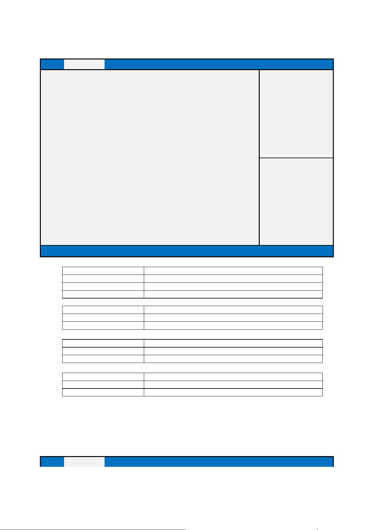
Help Determines how SATA controller(s) operate.
Field Name
Fi
eld Name
Default Value
Empty
Field Name
Default Value
Empty
Possible Value
SATA Device Model Name
SATA Configuration
Main Advanced Chipset Security Boot Save & Exit
Item help
SATA Mode Selection AHCI
Serial ATA Port 0 Empty
Serial ATA Port 1 Empty
MSATA Port Empty
Version 2.17.1249. Copyright (C) 2015 American Megatrends, Inc.
Field Name SATA Mode Selection
Default Value [AHCI]
Possible Value AHCI
→←: Select Screen
↑↓: Select Item
Enter: Select
+/- : Change Opt
F1: General Help
F2: Previous Values
F3: Optimized Defaults
F4: Save & Reset
ESC: Exit
Serial ATA Port 0
Default Value Empty
Possible Value SATA Device Model Name
Serial ATA Port 1
Possible Value SATA Device Model Name
MSATA Port
AMI Graphic Output Protocol Policy
Main Advanced Chipset Security Boot Save & Exit
34
Page 35
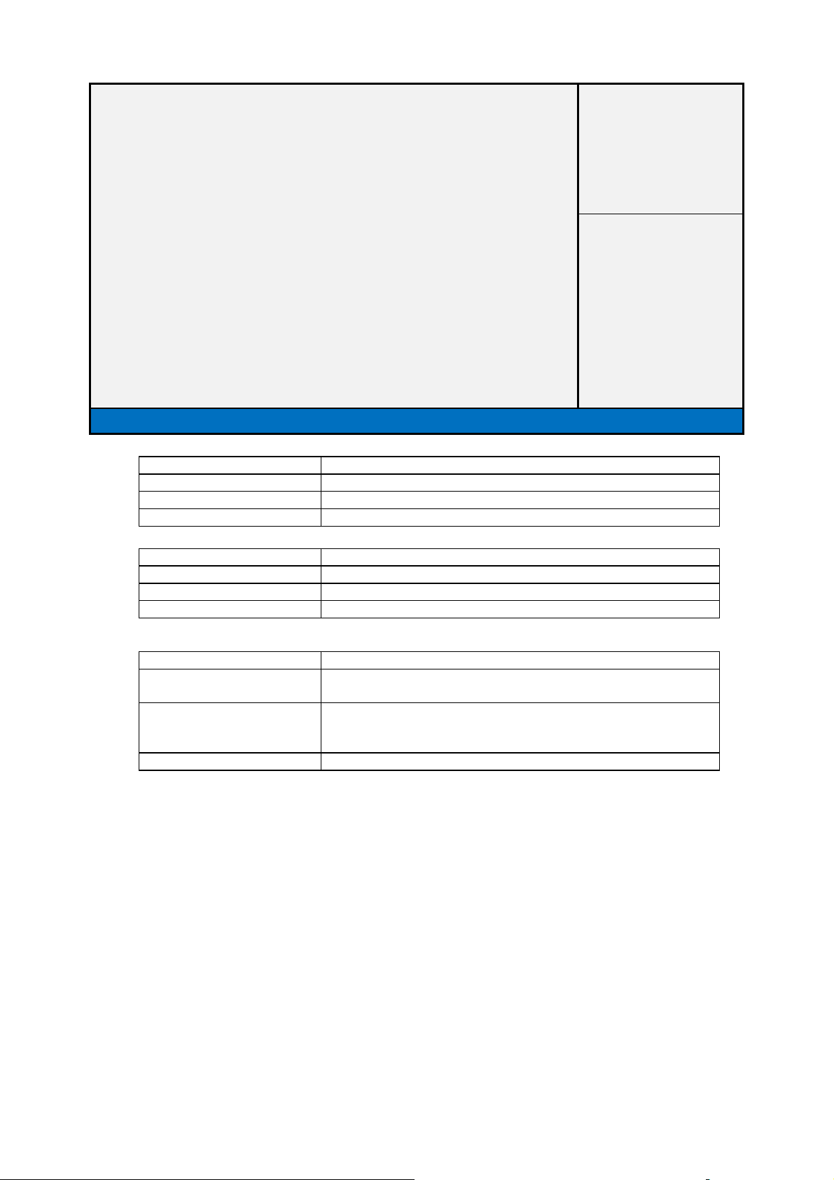
Field Name
Default Value
By Graphic card
Possible Value
By Graphic card
Help NA
Field Name
Default Value
By Graphic card
Possible Value
By Graphic card
Help NA
Field Name
Output Device 3
Intel (R) Skylake Graphics Controller
Intel (R) GOP Driver [9.0.1022]
Output Select [Output Devices]
Version 2.17.1249. Copyright (C) 2015 American Megatrends, Inc.
Display Device Name
Item help
→←: Select Screen
↑↓: Select Item
Enter: Select
+/- : Change Opt
F1: General Help
F2: Previous Values
F3: Optimized Defaults
F4: Save & Reset
ESC: Exit
Display Device Driver Version Information
Output Select
Default Value Dynamic generate by graphic GOP driver, no fixed name for
LCD/HDMI-Out
Possible Value Output Device 1
Output Device 2
Help Output Interface
35
Page 36
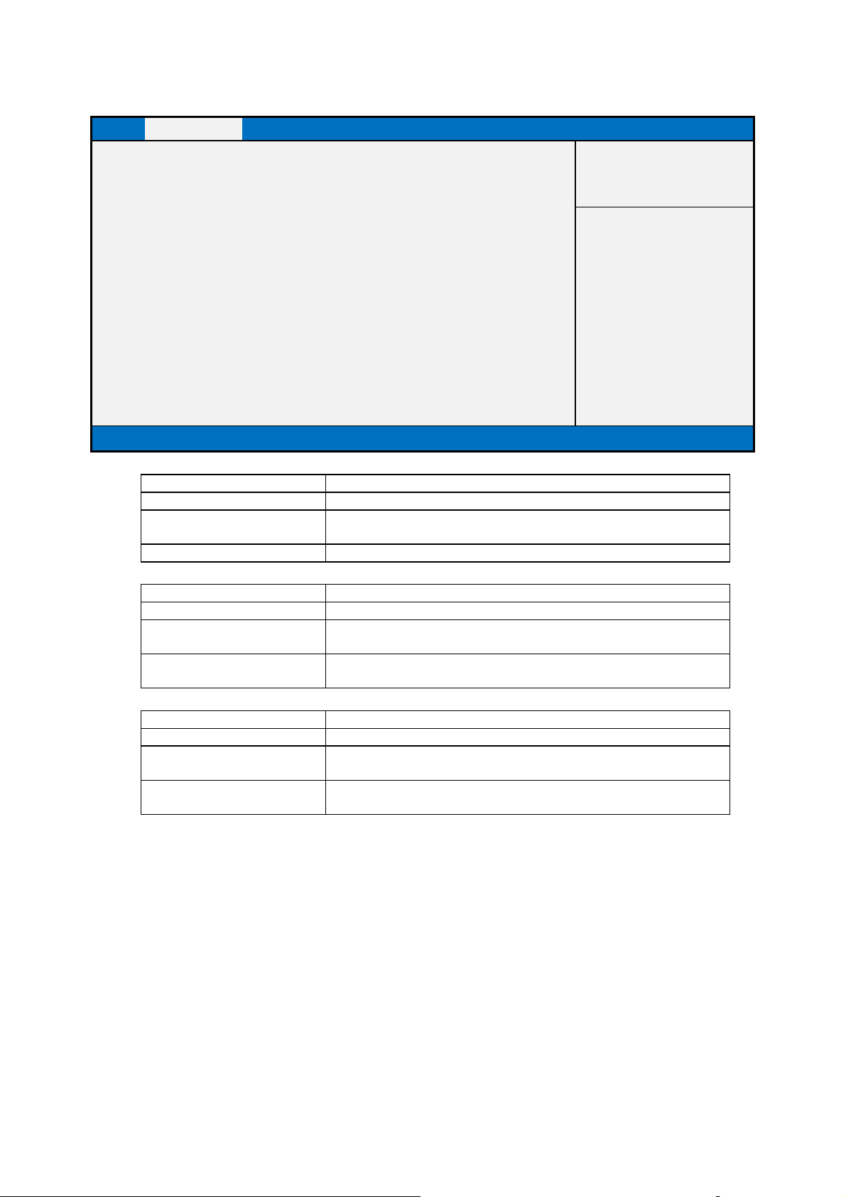
Field Name
D
efault Value
[Enabled]
Help Enable/Disable UEFI
N
etwork stack.
Field Name
Enabled
oot Support. If disabled IPV4 PXE boot option will
Field Name
Default Value
[Enabled]
Enable Ipv6 PXE Boot Support. If disabled IPV6 PXE boot option will
not be created.
Network Stack Configuration
Main Advanced Chipset Security Boot Save & Exit
Item help
Network stack [Enabled]
Ipv4 PXE Support [Enabled]
Ipv6 PXE Support [Enabled]
Version 2.17.1254. Copyright (C) 2015 American Megatrends, Inc.
Network stack
Possible Value Disabled (Restore Legacy Default)
Enabled (Restore UEFI Default)
Ipv4 PXE Support
Default Value [Enabled]
Possible Value Disabled
→←: Select Screen
↑↓: Select Item
Enter: Select
+/- : Change Opt
F1: General Help
F2: Previous Values
F3: Restore Legacy defaults
F4: Save & Reset
ESC: Exit
Help Enable Ipv4 PXE B
Possible Value Disabled
Help
not be created.
Ipv6 PXE Support
Enabled
36
Page 37
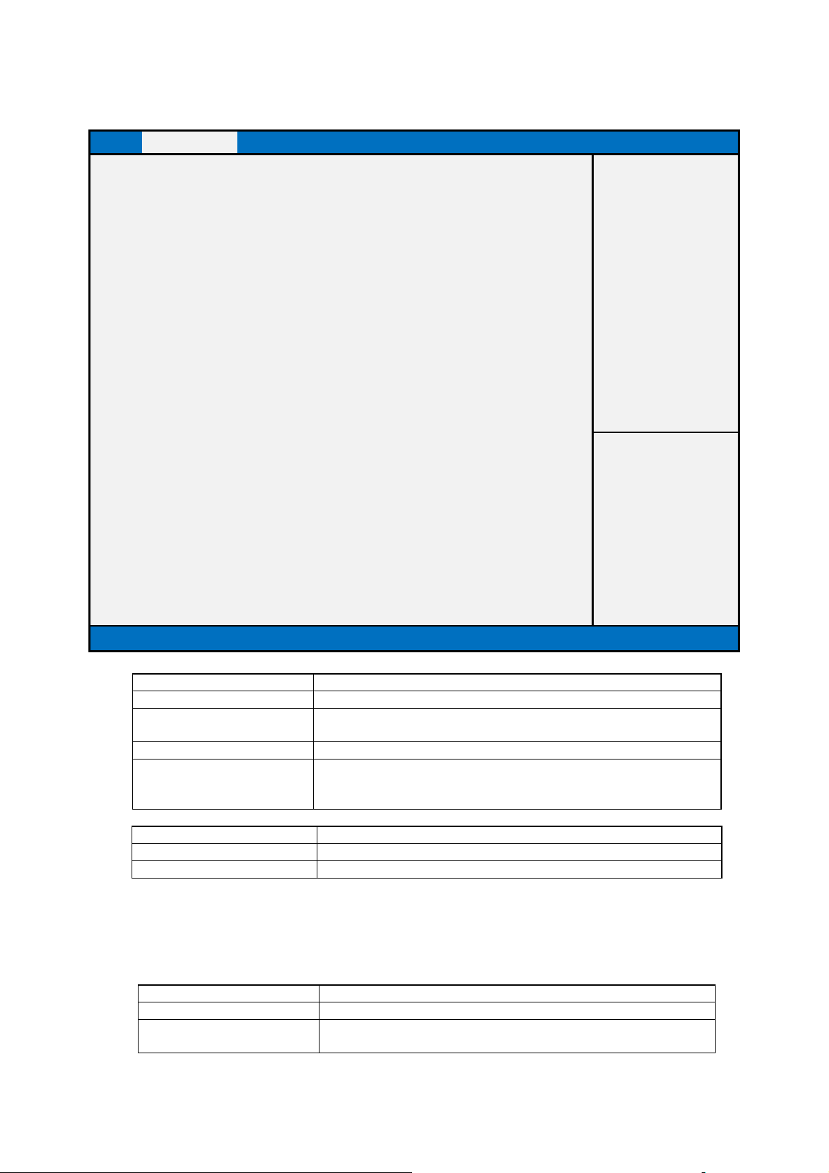
Default Value
Disabled
it only
Default Value
07.78
Comment
This field is not selectable. There is no help text associated with it.
Defa
ult Value
[UEFI]
CSM Configuration
Main Advanced Chipset Security Boot Save & Exit
Compatibility Support Module Configuration
Item help
CSM Support [Disabled]
CSM16 Module Version 07.78
Option Rom execution
Network [UEFI]
Video [UEFI]
Version 2.17.1249. Copyright (C) 2015 American Megatrends, Inc.
→←: Select Screen
↑↓: Select Item
Enter: Select
+/- : Change Opt
F1: General Help
F2: Previous Values
F3: Optimized Defaults
F4: Save & Reset
ESC: Exit
Field Name CSM support
Possible Value [Enabled] (Restore Legacy Default)
[Disabled] (Restore UEFI Default)
Help Enable/Disable CSM Support.
Comment This option controls if CSM will be launched. (It can’t be selected,
shows the status of the PXE OpROM’s status , it can be changed by
Restore UEFI defaults & Restore Legacy defaults.)
Field Name CSM16 Module Version
Field Name Network
Possible Value DO not launch
UEFI
37
Page 38

Help Controls the execution of UEFI and Legacy
PXE OpROM
.
[
UEFI
] (Restore
UEFI
Default)
Help Controls t
he execution of UEFI and Legacy Video OpROM.
Legacy
Field Name Video
Default Value [UEFI]
Possible Value [Legacy] (Restore Legacy Default)
38
Page 39
Field Name
Field Name
Default Value
[Enabled]
Auto
no USB devices are connected. DISABLE option will keep USB devices
Field Name
Enabled
Field Name
Default Value
[Enabled]
no USB devices are connected. DISABLE option will keep USB devices
Default Value
[Disabled]
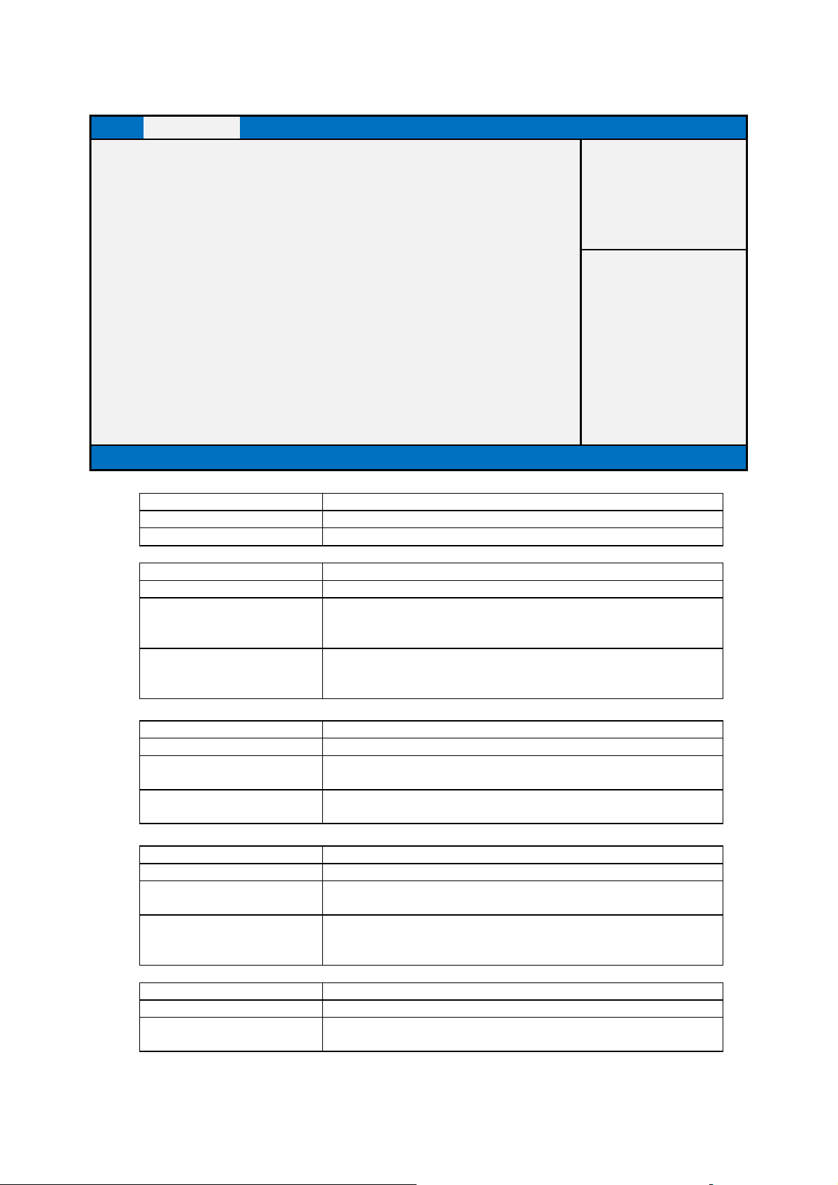
USB Configuration
Main Advanced Chipset Security Boot Save & Exit
USB Configuration
Item help
USB Devices:
1 Keyboard, 1 Mouse, 2 Hubs
Legacy USB Support [Enabled]
XHCI Hand-off [Disabled]
USB Mass Storage Driver Support [Enabled]
Port 60/64 Emulation [Disabled]
Version 2.17.1249. Copyright (C) 2015 American Megatrends, Inc.
USB Devices:
Default Value Connected USB devices
Comment This field is not selectable. There is no help text associated with it.
Legacy USB Support
→←: Select Screen
↑↓: Select Item
Enter: Select
+/- : Change Opt
F1: General Help
F2: Previous Values
F3: Optimized Defaults
F4: Save & Reset
ESC: Exit
Possible Value Disabled
Enabled
Help Enables Legacy USB support. AUTO option disables legacy support if
available only for EFI applications.
XHCI Hand-off
Default Value [Disabled]
Possible Value Disabled
Help This is a workaround for OSes without XHCI hand-off support. The
XHCI ownership change should be claimed by XHCI driver.
USB Mass Storage Driver Support
Possible Value Disabled
Enabled
Help Enables Legacy USB support. AUTO option disables legacy support if
available only for EFI applications.
Field Name Port 60/64 Emulation
Possible Value Disabled
Enabled
39
Page 40

Enables I/O port 60h/64h emulation support. This should be enabled for
the complete USB keyboard legacy support for non
-
USB aware OSes.
Help
40
Page 41
Field Name
Help System Agent (SA) Parameters
Comment
Press Enter when selected to go into the associated Sub
-
Menu.
Comment
Press Enter when selected to go into the associated Sub
-
Menu.
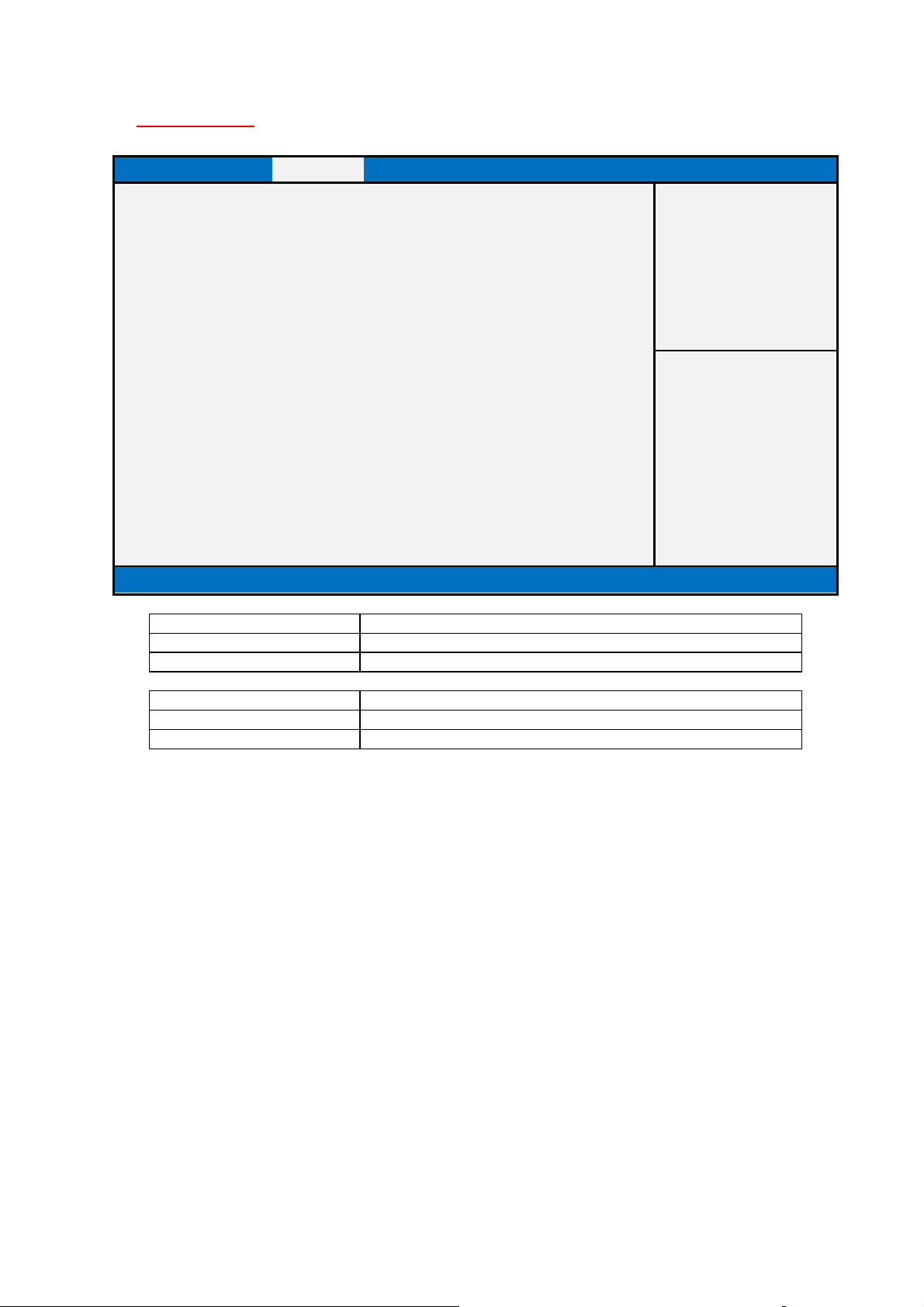
Chipset Page
Main Advanced Chipset Security Boot Save & Exit
►System Agent (SA) Configuration
Item help
►PCH-IO Configuration
Version 2.17.1249. Copyright (C) 2015 American Megatrends, Inc.
System Agent (SA) Configuration
→←: Select Screen
↑↓: Select Item
Enter: Select
+/- : Change Opt
F1: General Help
F2: Previous Values
F3: Optimized Defaults
F4: Save & Reset
ESC: Exit
Field Name PCH-IO Configuration
Help PCH Parameters
41
Page 42
Field Name
Help Memory Configuratio
n Parameters
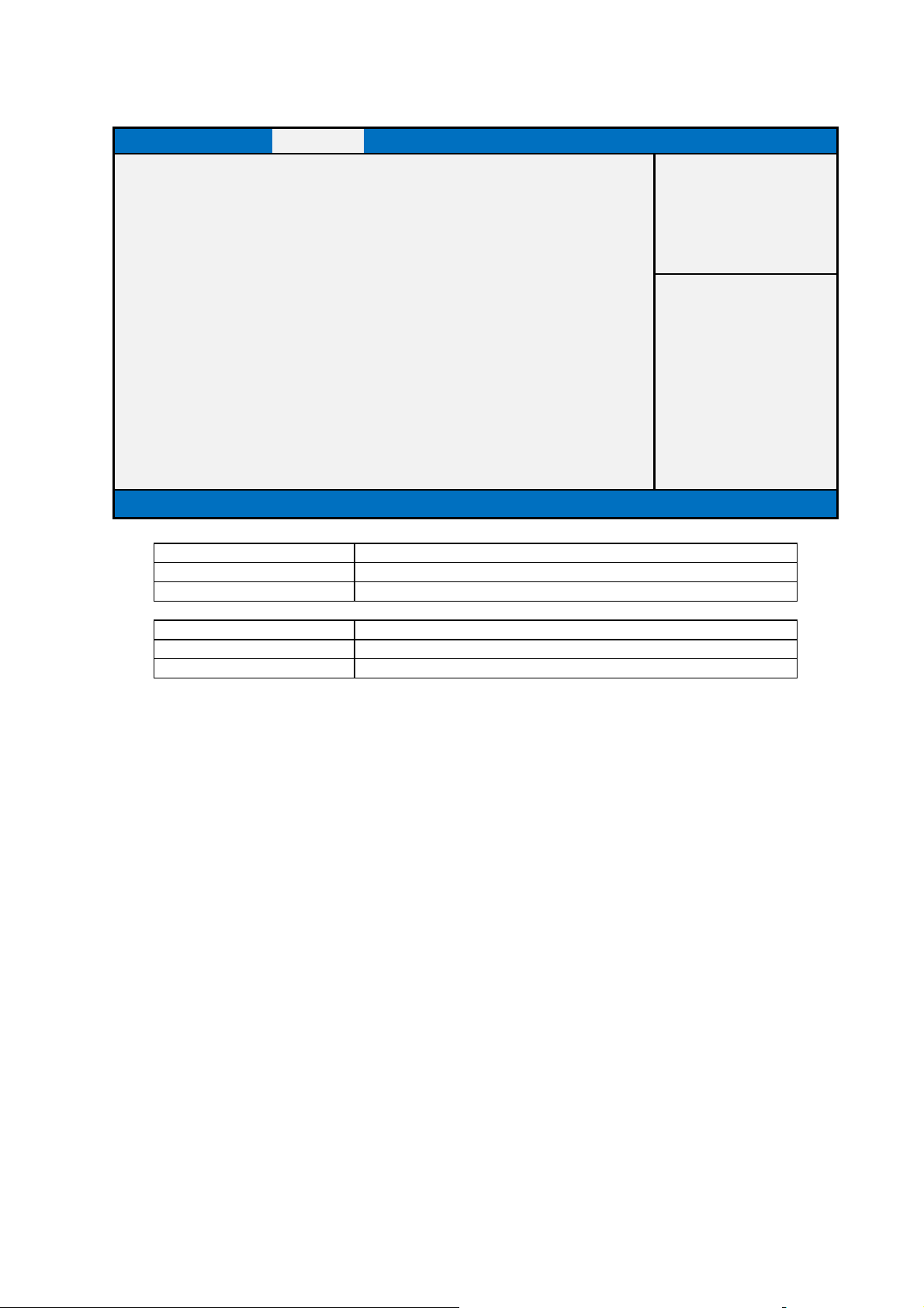
System Agent (SA) Configuration
Main Advanced Chipset Security Boot Save & Exit
►Graphics Configuration
Item help
►Memory Configuration
Version 2.17.1249. Copyright (C) 2015 American Megatrends, Inc.
→←: Select Screen
↑↓: Select Item
Enter: Select
+/- : Change Opt
F1: General Help
F2: Previous Values
F3: Optimized Defaults
F4: Save & Reset
ESC: Exit
Field Name Graphics Configuration
Help Config Graphics Settings.
Comment Press Enter when selected to go into the associated Sub-Menu.
Memory Configuration
Comment Press Enter when selected to go into the associated Sub-Menu.
42
Page 43
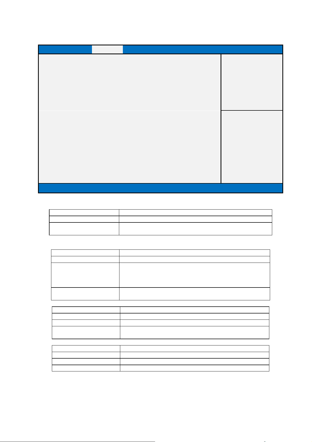
Field Name
IGFX VBIOS version
Default Value
1024
Default Value
[32M]
36M/ 40M/ 44M/ 48M/ 52M
/
56M/ 60M
ted (Fixed) Graphics Memory size used by
Field Name
Default Value
[256M]
Possible Value
128MB / 256MB / MAX
Field Na
me
Default Value
[LVDS Panel
]
Possible Value
LVDS Panel
/ VGA Display
Graphics Configuration
Main Advanced Chipset Security Boot Save & Exit
Graphics Configuration
IGFX VBIOS version 1024
DVMT Pre-Allocated [32M]
DVMT Total Gfx Mem [256M]
Primary IGFX Boot Display [LVDS Panel]
Version 2.17.1249. Copyright (C) 2015 American Megatrends, Inc.
Item help
→←: Select Screen
↑↓: Select Item
Enter: Select
+/- : Change Opt
F1: General Help
F2: Previous Values
F3: Optimized Defaults
F4: Save & Reset
ESC: Exit
Comment Show Legacy VBIOS’s version.(The Item only show up in the Legacy
mode.)
Field Name DVMT Pre-Allocated
Possible Value 32M / 64M / 96M / 128M / 160M / 192M / 224M / 256M / 288M
/320M / 352M / 384M / 416M / 448M / 480M / 512M/ 1024M/
1536M/ 2048M/ 4M/ 8M/ 12M/ 16M/ 20M/ 24M/ 28M/ (32M/F7)/
Help Select DVMT 5.0 Pre-Alloca
the Internal Graphics Device.
DVMT Total Gfx Mem
Help Select DVMT5.0 Total Graphic Memory size used by the Internal
Graphics Device.
Primary IGFX Boot Display
Help Select the Video Device Which will be activated In the DOS.
43
Page 44
Comment
This field is not selectable. There is no help text associated with it.
Field
Name
Field Name
Default Value
Memory in the DIMM.
Comment
This field is not selectable. There is no help tex
t associated with it.
Default Value
Memory in the DIMM.
Comment
This field is not selectable. There is no help text associated with it.
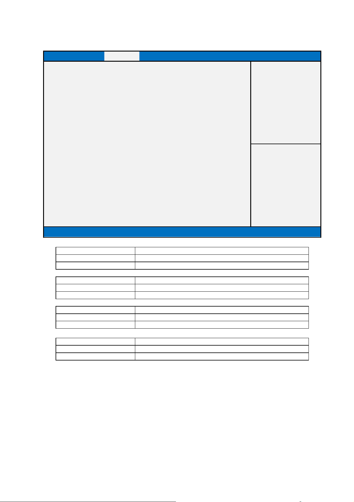
Memory Configuration
Main Advanced Chipset Boot Security Save & Exit
Memory Information
Memory Frequency 2133 Mhz
Total Memory 8192 MB
DIMM#0 8192 MB
DIMM#1
Version 2.17.1249. Copyright (C) 2015 American Megatrends, Inc.
Item help
→←: Select Screen
↑↓: Select Item
Enter: Select
+/- : Change Opt
F1: General Help
F2: Previous Values
F3: Optimized Defaults
F4: Save & Reset
ESC: Exit
Field Name Memory Frequency
Default Value Show Memory Frequency.
Default Value Total Memory in the System.
Comment This field is not selectable. There is no help text associated with it.
Field Name DIMM#1
Total Memory
DIMM#0
44
Page 45
[Disabled]
Help Customizable Secure Boot settings
Comment
HD Audio Subsystem Configuration Settings
Default
Value
[Disabled]
S5 State
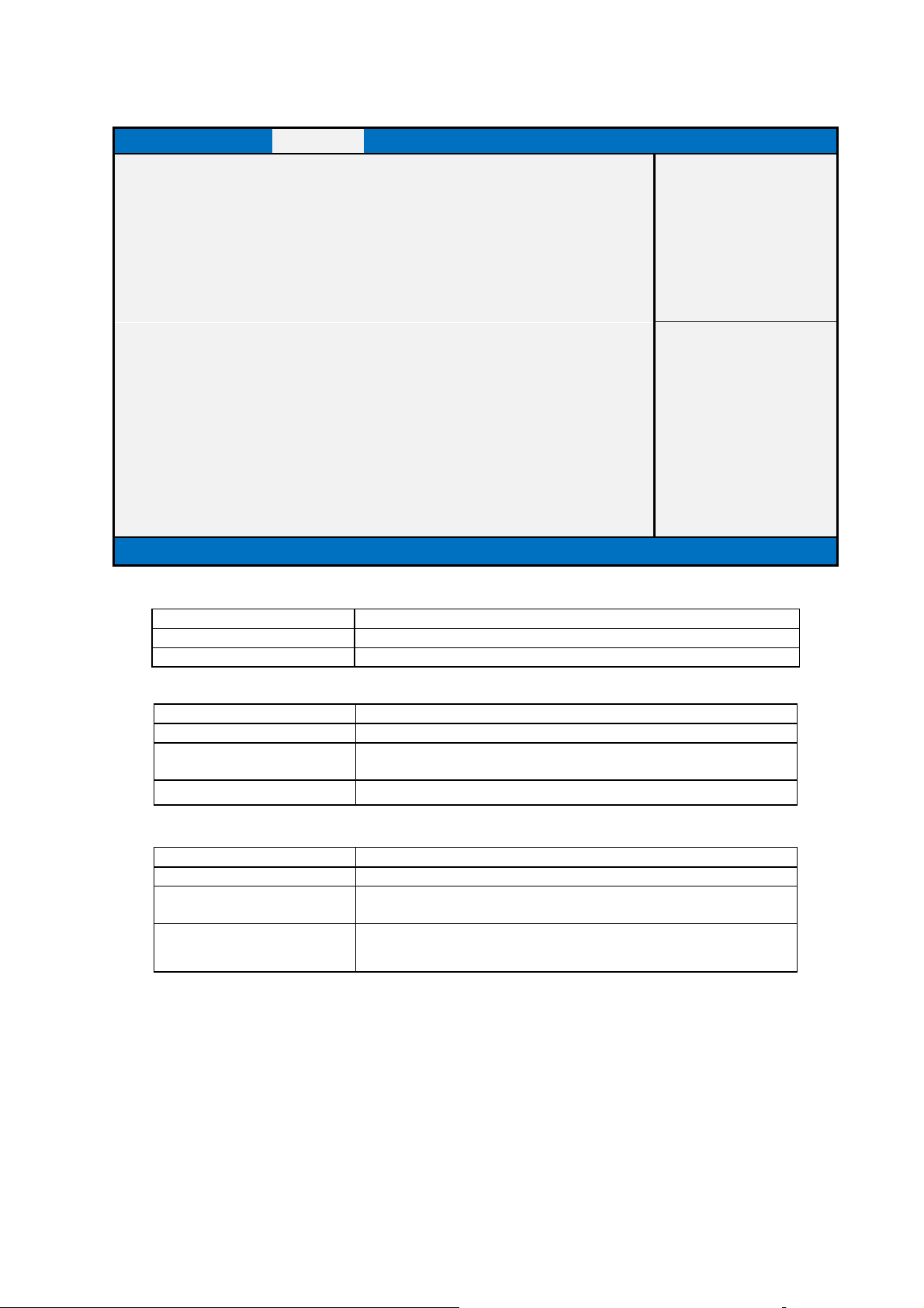
PCH-IO Configuration
Main Advanced Chipset Security Boot Save & Exit
Item help
►HD Audio Configuration
DeepSx Power Policies
State After G3 [S5 State]
Version 2.17.1249. Copyright (C) 2015 American Megatrends, Inc.
Field Name HD Audio Configuration
→←: Select Screen
↑↓: Select Item
Enter: Select
+/- : Change Opt
F1: General Help
F2: Previous Values
F3: Optimized Defaults
F4: Save & Reset
ESC: Exit
Field Name DeepSx Power Policies
Possible Value Disabled
Enabled in S4-S5
Help Configure the DeepSx Mode configuration.
Field Name State After G3
Default Value [S5 State]
Possible Value S0 State
Help Specify what state to go to when power is re-applied after a power
failure (G3 state).
45
Page 46
Field Name
Value
[Auto]
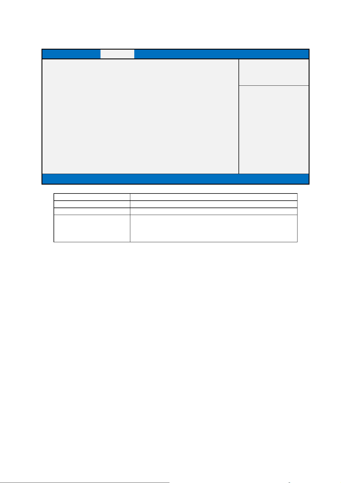
HD Audio Configuration
Main Advanced Chipset Boot Security Save & Exit
HD Audio Configuration
HD Audio [Auto]
Version 2.17.1254. Copyright (C) 2015 American Megatrends, Inc.
HD Audio
Item help
→←: Select Screen
↑↓: Select Item
Enter: Select
+/- : Change Opt
F1: General Help
F2: Previous Values
F3: Restore Legacy defaults
F4: Save & Reset
ESC: Exit
Possible Value Auto / Enable / Disable
Help Control Detection of HD-Audio device.
Disabled = HDA will be unconditionally disabled
Enable = HDA will be unconditionally enabled
Auto = HDA will be enabled if present, disabled otherwise.
46
Page 47
Field Name
Help Set Setup Administrator Password
Comment
Press Enter when selected to go into the associated Sub
-
Menu.
Security Page
Main Advanced Chipset Security Boot Save & Exit
Password Description
Item help
If the Administrator's password is set,
then this only limits access to Setup and is
only asked for when entering Setup.
The password length must be
in the following range:
Minimum Length 3
Maximum Length 20
Administrator Password
►Secure Boot menu
Version 2.17.1249. Copyright (C) 2015 American Megatrends, Inc.
→←: Select Screen
↑↓: Select Item
Enter: Select
+/- : Change Opt
F1: General Help
F2: Previous Values
F3: Optimized Defaults
F4: Save & Reset
ESC: Exit
Administrator Password
Comment Press Enter when selected to go into the associated Sub-Menu.
Field Name Secure Boot menu
Help Customizable Secure Boot settings
47
Page 48
Field Name
Default Value
[Disabled]
Key (PK) 2. CSM function is disabled.
Custom
Field Name
Secure Boot Mode
Main Advanced Chipset Security Boot Save & Exit
Item help
System Mode Setup
Secure Boot Not Active
Secure Boot [Disabled]
Secure Boot Mode [Standard]
► Key Management
Version 2.17.1249. Copyright (C) 2015 American Megatrends, Inc.
Secure Boot
→←: Select Screen
↑↓: Select Item
Enter: Select
+/- : Change Opt
F1: General Help
F2: Previous Values
F3: Optimized Defaults
F4: Save & Reset
ESC: Exit
Possible Value Enabled
Disabled
Help Secure Boot can be enabled if 1.System running in User mode with enrolled Platform
Field Name Secure Boot Mode
Default Value [Custom]
Possible Value Standard
Help Secure Boot mode selector. 'Custom' Mode enables users to change
Image Execution policy and manage Secure Boot Keys..
Key Management
Help Enables experienced users to modify Secure Boot variables
Comment Press Enter when selected to go into the associated Sub-Menu.
48
Page 49
0
0
0
0
0
Default Value
[Disabled
]
Disabled
Field Name
dbt).
Field Name
Comment
1.Public Key Certificate in:
Key Management
Main Advanced Chipset Security Boot Save & Exit
Provision Factory Default keys [Disabled]
Item help
► Enroll All Factory Default Keys
► Save All Secure Boot Variables
Secure Boot variable Size
► Platform Key(PK) 0
► Key Exchange Key 0
► Authorized Signatures 0
► Forbidden Signatures 0
► Authorized TimeStamps 0
Key# Key source
Version 2.17.1249. Copyright (C) 2015 American Megatrends, Inc.
→←: Select Screen
↑↓: Select Item
Enter: Select
+/- : Change Opt
F1: General Help
F2: Previous Values
F3: Optimized Defaults
F4: Save & Reset
ESC: Exit
Field Name Provision Factory Default Keys
Possible Value Enabled
Help Install Factory default Secure Boot Keys when System is in Setup Mode.
Enroll All Factory Default Key
Help Force System to User Mode - install all Factory Default keys(PK, KEK, db, dbx,
Change takes effect after reboot
Comment
Save All Secure Boot Variables
Help Save NVRAM content of all Secure Boot variables to the files
(EFI_SIGNATURE_LIST data format) in root folder on a target files system device.
Field Name Platform Key (PK)
Default Value Size:0, Key#:0, Key source: *
Help Insert Factory Default Keys or load from a file formatted as:
49
Page 50
comment
Press Enter when selected to go into the associated Sub
-
Menu
“Key Management
”.
Field Name
Default Value
Size:0, Key
#:0, Key source: *
Key source: Default, Custom, Mixed (*) modified through Setup menu
comment
Press Enter when selected to go into the associated Sub
-
Menu.
Default Value
Size:0, Key#:0, Key source: *
comment
Press Enter when selected to go into the associated Sub
-
Menu.
2.
Authenticated UEFI Variable
a)EFI_SIGNATURE_LIST,
b)EFI_CERT_X509 (DER encoded),
c)EFI_CERT_RSA2048 (bin),
d)EFI_CERT_SHA256 (bin)
2.Authenticated UEFI Variable
Key source: Default, Custom, Mixed (*) modified through Setup menu
Field Name Key Exchange Key
Default Value Size:0, Key#:0, Key source: *
Help Insert Factory Default Keys or load from a file formatted as:
1.Public Key Certificate in:
a)EFI_SIGNATURE_LIST,
b)EFI_CERT_X509 (DER encoded),
c)EFI_CERT_RSA2048 (bin),
d)EFI_CERT_SHA256 (bin)
2.Authenticated UEFI Variable
Key source: Default, Custom, Mixed (*) modified through Setup menu
comment Press Enter when selected to go into the associated Sub-Menu.
Authorized Signature
Help Insert Factory Default Keys or load from a file formatted as:
1.Public Key Certificate in:
a)EFI_SIGNATURE_LIST,
b)EFI_CERT_X509 (DER encoded),
c)EFI_CERT_RSA2048 (bin),
d)EFI_CERT_SHA256 (bin)
2.Authenticated UEFI Variable
Field Name Forbidden Signature
Help Insert Factory Default Keys or load from a file formatted as:
1.Public Key Certificate in:
a)EFI_SIGNATURE_LIST,
b)EFI_CERT_X509 (DER encoded),
c)EFI_CERT_RSA2048 (bin),
d)EFI_CERT_SHA256 (bin)
2.Authenticated UEFI Variable
Key source: Default, Custom, Mixed (*) modified through Setup menu
Field Name Authorized TimeStamps
Default Value Size:0, Key#:0, Key source: *
Help Insert Factory Default Keys or load from a file formatted as:
1.Public Key Certificate in:
a)EFI_SIGNATURE_LIST,
b)EFI_CERT_X509 (DER encoded),
c)EFI_CERT_RSA2048 (bin),
d)EFI_CERT_SHA256 (bin)
50
Page 51

Key source: Default, Custom, Mixed (*) modified through Setup menu
comment
Press Enter when selected to
go into the associated Sub
-
Menu.
51
Page 52
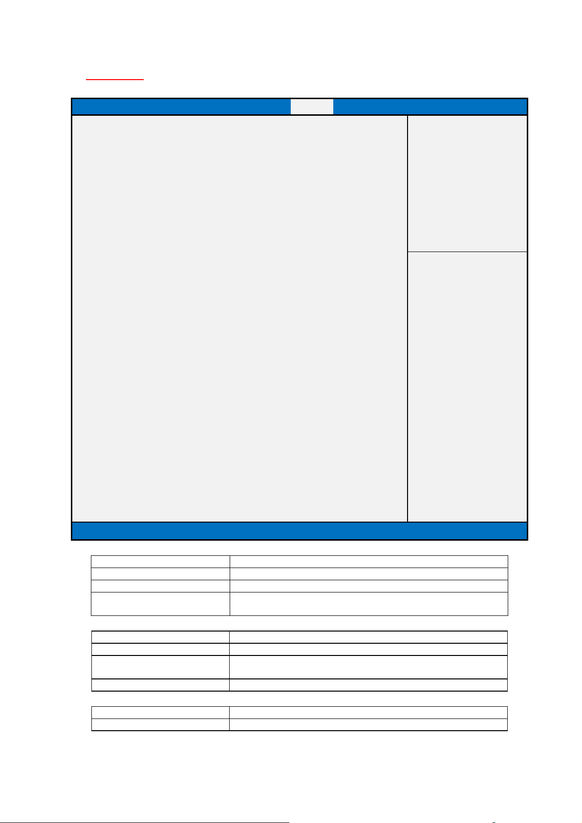
means indefinite waiting.
Default Value
[On]
Field Name
Default Value
[Enabled]
Boot Page
Main Advanced Chipset Security Boot Save & Exit
Boot Configuration
Item help
Setup Prompt Timeout 1
Bootup NumLock State [On]
Quiet Boot [Enabled]
Fast Boot [Enabled]
Boot mode select [LEGACY]
FIXED BOOT ORDER Priorities
Boot Option #1 [Hard Disk]
Boot Option #2 [CD/DVD]
Boot Option #3 [USB Hard Disk]
Boot Option #4 [USB CD/DVD]
Boot Option #5 [USB Key]
Boot Option #6 [USB USB Floppy]
Boot Option #7 [USB Lan]
Boot Option #8 [Network]
►
CD/DVD ROM Drive BBS Priorities
►
Hard Disk Drive BBS Priorities
►
NETWORK Drive BBS Priorities
►
USB CD/DVD ROM Drive BBS Priorities
►
USB Hard Disk Drive BBS Priorities
►
USB KEY Drive BBS Priorities
Version 2.17.1254. Copyright (C) 2015 American Megatrends, Inc.
→←: Select Screen
↑↓: Select Item
Enter: Select
+/- : Change Opt
F1: General Help
F2: Previous Values
F3: Restore Legacy defaults
F4: Save & Reset
ESC: Exit
Field Name Setup Prompt Timeout
Default Value 1
Possible Value 1~65535
Help Number of seconds to wait for setup activation key. 65535(0xFFFF)
Field Name Boot NumLock State
Possible Value On
Off
Help Select the keyboard NumLock state
Quiet Boot
52
Page 53
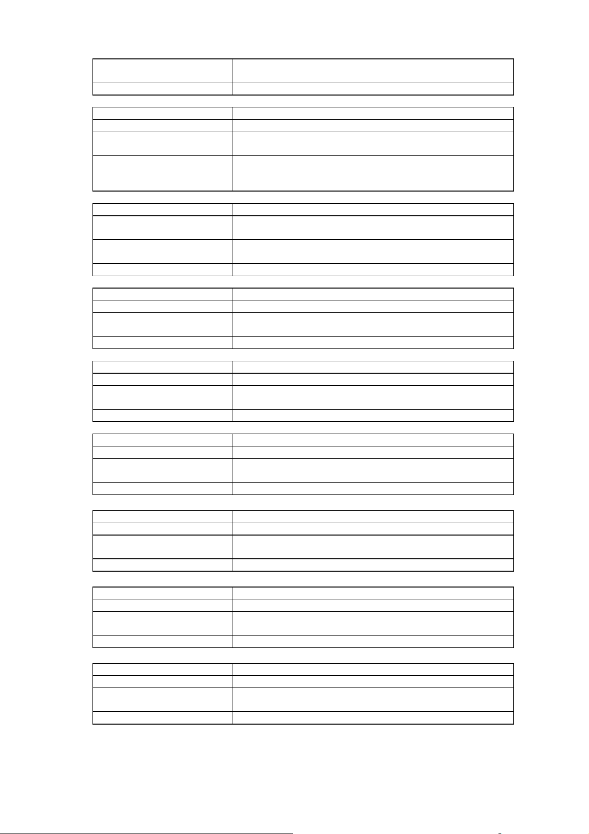
Disabled
Help Enables or Disables Quiet Boot option
Disabled
options.
Field Name
[
UEFI
] (Restore
UEFI
Default)
UEFI
Field Name
Default Value
[Hard Disk]
Hard Disk, CD/DVD, USB Hard Disk, USB CD/DVD, USB Key, USB
Field Name
Default Value
[CD/DVD]
Hard Disk, CD/DVD, USB Hard Disk, USB CD/DVD, USB Key, USB
Help Sets the system boot order
Field Name
Default Value
[USB Hard Disk]
Disk, CD/DVD, USB Hard Disk, USB CD/DVD, USB Key, USB
Floppy , USB Lan, Network, Disabled
Help Sets the system boot order
Hard Disk, CD/DVD, USB Hard Disk, USB CD/DVD, USB Key, USB
F
loppy , USB Lan, Network, Disabled
Field Name
Default Value
[USB Key]
Hard Disk, CD/DVD, USB Hard Disk, USB CD/DVD, USB Key, USB
Field Name
Hard Disk, CD/DVD, USB Hard Disk, USB CD/DVD, USB Key, USB
Floppy , USB Lan, Network, Disabled
Help Sets the system boot order
Possible Value Enabled
Field Name Fast Boot
Default Value [Enabled]
Possible Value Enabled
Help Enables or disables boot with initialization of a minimal set of devices
required to launch active boot option. Has no effect for BBS boot
Boot mode select
Default Value [LEGACY] (Restore Legacy Default)
Possible Value LEGACY
Help Select boot mode LEGACY/UEFI.
Boot Option #1
Possible Value
Floppy , USB Lan, Network, Disabled
Help Sets the system boot order
Boot Option #2
Possible Value
Floppy , USB Lan, Network, Disabled
Boot Option #3
Possible Value Hard
Field Name Boot Option #4
Default Value [USB CD/DVD]
Possible Value
Help Sets the system boot order
Boot Option #5
Possible Value
Floppy , USB Lan, Network, Disabled
Help Sets the system boot order
Boot Option #6
Default Value [USB Floppy]
Possible Value
53
Page 54

Default Value
[USB
Lan]
Hard Disk, CD/DVD, USB Hard Disk, USB CD/DVD, USB Key, USB
Floppy , USB Lan, Network, Disabled
Field Name
Default Value
[Network]
CD/DVD, USB Key, USB
Help Sets the system boot order
CDROM/DVD Drives.
Comment
Press Enter when sel
ected to go into the associated Sub
-
Menu.
Drives.
Comment
Press Enter when selected to go into the associated Sub
-
Menu.
Field
Name
Specifies the Boot Device Priority sequence from available NETWORK
Drives.
Field Name
CDROM/DVD Drives.
Field Name
Disk Drives.
Field Name
Specifies the Boot Device Priority sequence from available USB Floppy
Drives.
Comment
Press Enter when selected to g
o into the associated Sub
-
Menu.
Field Name Boot Option #7
Possible Value
Help Sets the system boot order
Boot Option #8
Possible Value Hard Disk, CD/DVD, USB Hard Disk, USB
Floppy , USB Lan, Network, Disabled
Field Name (UEFI) CD/DVD ROM Drive BBS Priorities
Help Specifies the Boot Device Priority sequence from available
Field Name (UEFI) Hard Disk Drive BBS Priorities
Help Specifies the Boot Device Priority sequence from available Hard Disk
(UEFI) NETWORK Drive BBS Priorities
Help
Comment Press Enter when selected to go into the associated Sub-Menu.
(UEFI) USB CD/DVD ROM Drive BBS Priorities
Help Specifies the Boot Device Priority sequence from available USB
Comment Press Enter when selected to go into the associated Sub-Menu.
(UEFI) USB Hard Disk Drive BBS Priorities
Help Specifies the Boot Device Priority sequence from available USB Hard
Comment Press Enter when selected to go into the associated Sub-Menu.
(UEFI) USB KEY Drive BBS Priorities
Help Specifies the Boot Device Priority sequence from available USB Key
Drives.
Comment Press Enter when selected to go into the associated Sub-Menu.
Field Name USB Floppy Drive BBS Priorities
(UEFI Boot Mode Not Support)
Help
54
Page 55
Fiel
d Name
Default Value
Possible Value
Boot Device Name 1 of this type
Field Name
Default Value
Possible Value
Boot Device Name 2 of this type
1.1
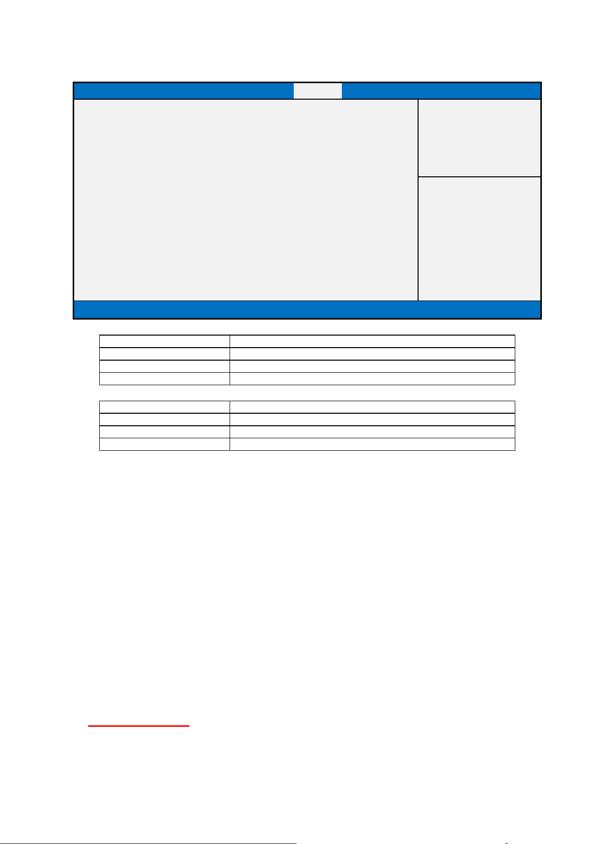
(List Boot Device Type) Drive BBS Priorities
Main Advanced Chipset Security Boot Save & Exit
Boot Option #1 [Boot Device Name 1]
Item help
Boot Option #2 [Boot Device Name 2]
Version 2.17.1254. Copyright (C) 2015 American Megatrends, Inc.
Boot Option #1
Help Sets the system boot order
Boot Option #2
→←: Select Screen
↑↓: Select Item
Enter: Select
+/- : Change Opt
F1: General Help
F2: Previous Values
F3: Restore Legacy defaults
F4: Save & Reset
ESC: Exit
Help Sets the system boot order
Save & Exit Page
55
Page 56
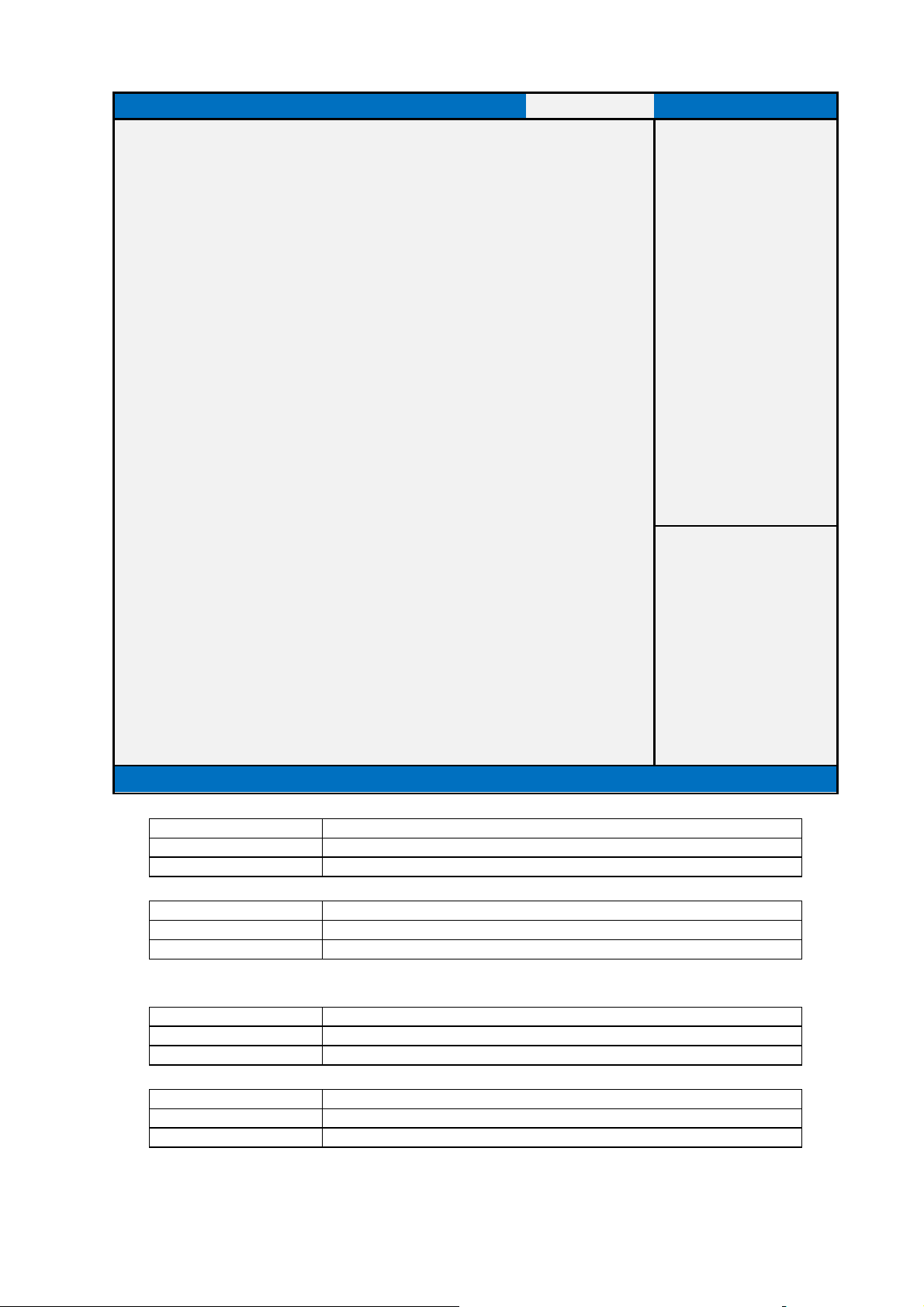
Help Reset the system after saving the changes.
Comment
Help Exit system setup with without saving any c
hanges.
Comment
Field Name
Help Reset system setup without saving any changes.
Field Name
Help Save Changes done so far to any of the setup options.
Comment
Main Advanced Chipset Security Boot Save & Exit
Save Options
Item help
Save Changes and Reset
Discard Changes and Reset
Discard Changes and Exit
Default Options
Restore UEFI Defaults
Restore Legacy Defaults
Save as user Defaults
Restore user Defaults
Boot Override
Version 2.17.1249. Copyright (C) 2015 American Megatrends, Inc.
→←: Select Screen
↑↓: Select Item
Enter: Select
+/- : Change Opt
F1: General Help
F2: Previous Values
F3: Optimized Defaults
F4: Save & Reset
ESC: Exit
Field Name Save Changes and Reset
Field Name Discard Changes and Exit
Discard Changes and Rest
Comment
Save Changes
56
Page 57

Help Disca
rd Changes done so far to any of the setup options.
Comment
10 64BIT .)Default values for all the setup options.
Comment
Field Name
Field Name
Field Name Discard Changes
Field Name
Help (Clear CMOS Defaults): Restore/Load UEFI (such as Windows 8 /
Comment
Field Name
Help Restore/Load Legacy (such as Windows XP / Windows 7 / Windows 8
Help Save the changes done so far as User Defaults.
Comment
Help Restore the User Defaults to all the setup options.
Comment
Restore UEFI Defaults
Restore Legacy Defaults
32BIT.) Default values for all the setup options.
Save as User Defaults
Restore User Defaults
57
 Loading...