

Page 1

MITAC Desktop Board PH10SU
Product Guide
Page 2
Support for up to 64 GB of system memory
Desktop Board Features
This chapter briefly describes the features of Desktop Board PH10SU.
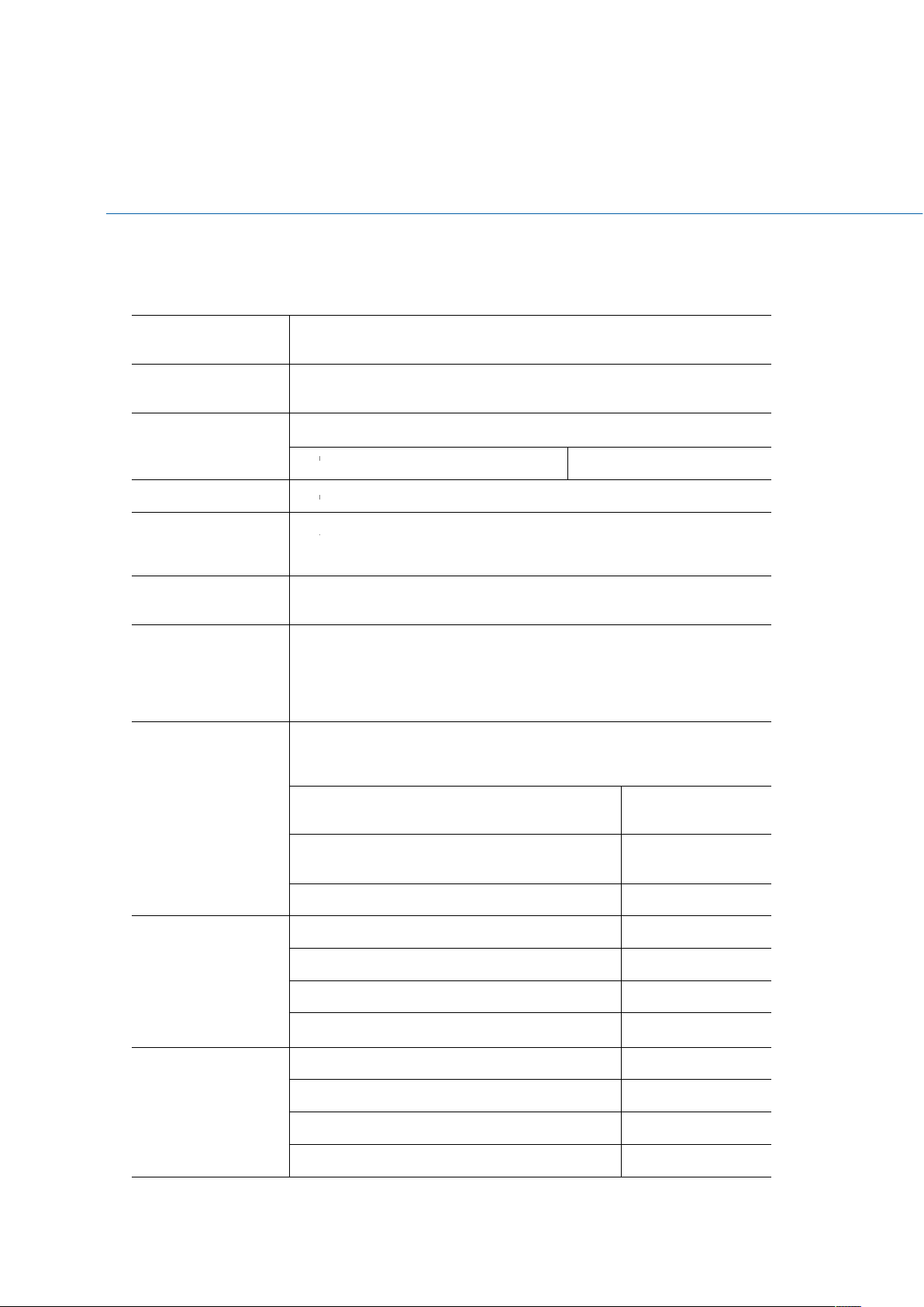
Table 1 summarizes the major features of the Desktop Board.
Feature Summary
AB L E
T
. MITAC D
Form Factor Micro-ATX (244 millimeters [9.6 inches] x 244 millimeters [9.6
inches])
Processor 6th generation Intel® Core processor family with up to 91 W TDP in
an LGA1151 socket
Main Memory Support Dual channel DDR4
288-pin DDR4 u-DIMM 4
Chipset Intel® Q170 Platform Controller Hub (PCH)
Integrated
Graphics
External Graphics
Intel® HD Graphics/ Iris Graphics (By CPU)
External graphics support provided through the PCIe 3.0 x16 bus
connector
ES K T OP BOA R D
PH10SU F
EA T URES
Audio
Legacy I/O
Expansion
Capabilities
Peripheral
RealTek* ALC662 audio codec for 5.1 (6-channel) High Definition
Audio (HD Audio) and AC ’97 Audio.
Front panel microphone/headphone header with support for HD
Audio or AC ’97 Audio
Legacy I/O Controller (Nuvoton* NCT6104D) that provides:
Hardware management support
Serial Port (Rear IO) 2 (Support power
S232)
Serial Port (On board) 2 (configurable for
RS232/422/485)
Parallel port via an onboard header 1
PCIe 3.0 x16 (Blue) 1
PCIe 2.0 x4 (Black) 1
PCIe 2.0 x1 (Black) 1
M.2 Suport Socket 3 Type2280, 2260, 2242
USB 3.0 back panel connectors (blue) 4
1
Interfaces
USB 2.0 back panel connectors (black) 2
USB 3.0 front panel ports 2 (Headers)
USB 2.0 front panel ports 2 (Headers)
2
Page 3
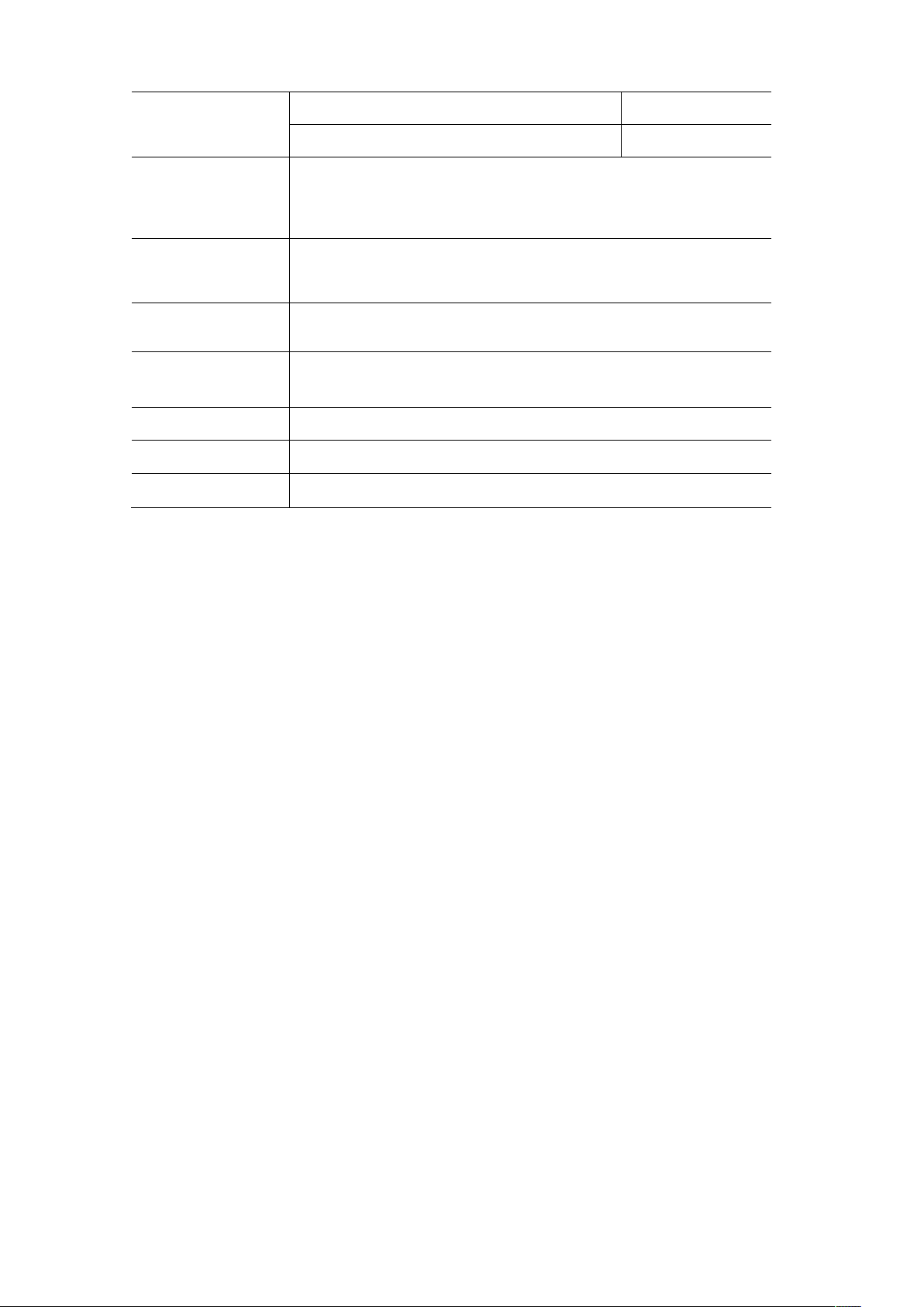
Serial ATA (SATA) 6.0 Gb/s interfaces 5
4-pin SATA power for DOM 1
Hardware Monitor
Subsystem
LAN Support
BIOS
Instantly Available
PC Technology
Power Requirement ATX12V
Environment
Safety
Hardware monitoring through the Nuvoton* NCT6104D legacy I/O
controller, including:
Remote thermal sensor
4-pin system fan header
Intel® I219 Gigabit (10/100/1000 Mb/s) LAN
Intel® I210 Gigabit (10/100/1000 Mb/s) LAN
AMI UEFI BIOS Support for Advanced Configuration and Power
Interface (ACPI)
Support for PCI Express Revision 3.0
Wake on USB, PCI Express, LAN, serial, PS/2, and front panel
Operating Temperature: 0 °C to +50 °C
Storage Temperature: -20°C to +70°C
CE
FCC
3
Page 4
Desktop Board Components
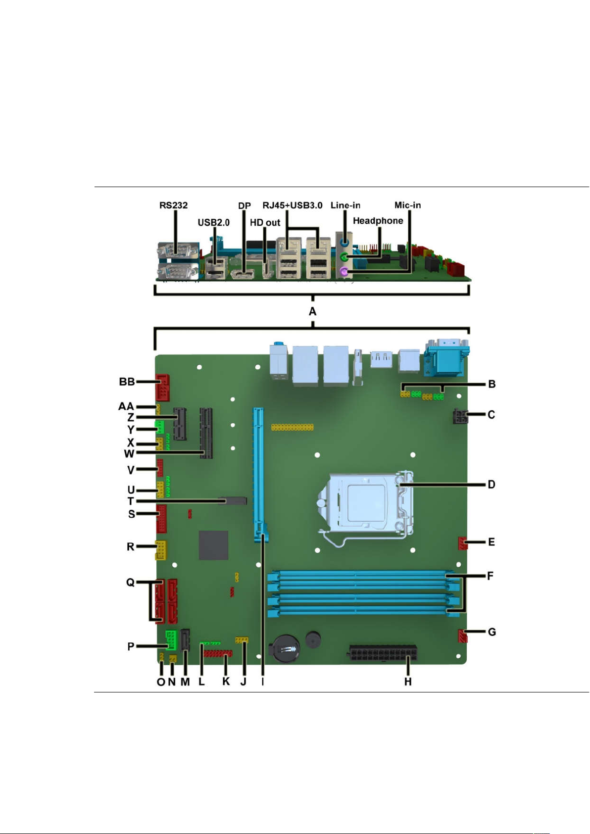
The
Figure shows the approximate location of the major components on the top side of
MiTAC Desktop Board PH10SU.
Fig ure 1. MiTAC Desktop Board PH1 0SU Com p onent s (Top)
4
Page 5

A
Back Panel Connectors
B
RS232 power select header
C
4-pin Power header
D
CPU Socket
E
CPU FAN header
F
DIMM Sockets
G
Front FAN header
H
ATX Power 24pin header
I
PCIe x16 slot
J
APS header
K
MiAPI header
L
MiAPI function select header
M
SATA Connector
N
Chassis Intrusion Header
O
CMOS clear header
P
Front panel main header
Q
SATA Connectors
R
Dual USB2.0 header
S
Dual USB3.0 header
T
M.2 slot
U
COM port header
V
Debug header
W
PCIe x4 slot
X
COM port header
Y
Rear FAN header
Z
PCIe x1 slot
AA
SPDIF Out header
BB
Front Audio header
AB L E
T
. MITA C D
ES K T OP BOA R D
PH 10S U C
OM P ONENT S
HO W N IN THE FIGU RE
( S
)
5
Page 6

Processor
The board supports 6th generation Intel Core processors. Other processors may be
supported in the future. This board supports processors with a maximum wattage of
91 W Thermal Design Power (TDP).
NOTE
This board has specific requirements for providing power to the processor. Additional
power required will depend on configurations chosen by the integrator.
System Memory
NOTE
To be fully compliant with all applicable DDR SDRAM memory specifications, the board
should be populated with DIMMs that support the Serial Presence Detect (SPD) data
structure. This allows the BIOS to read the SPD data and program the chipset to
accurately configure memory settings for optimum performance. If non-SPD memory
is installed, the BIOS will attempt to correctly configure the memory settings, but
performance and reliability may be impacted or the DIMMs may not function under the
determined frequency.
The Desktop Board has
These sockets support:
four
288-pin DDR4 u-DIMM sockets with gold-plated contacts.
Serial Presence Detect (SPD) memory only
Non-ECC memory
Up to 64 GB of memory
6
Page 7

MITAC Desktop Board PH10SU
Hardware Specifiction
Page 8
1. Platform Definition
1.1 Major Sub-systems
1.1.1 System Memory
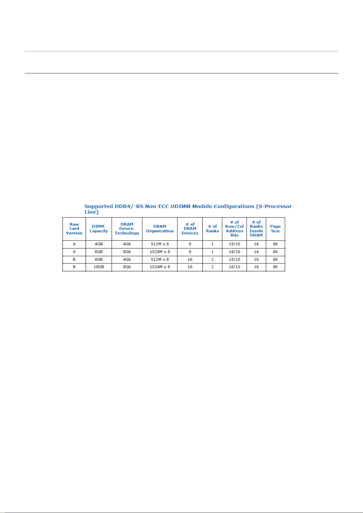
Board must support the following memory configurations. .
• DDR4/-RS 1866MHz to 2133MHz or maximum multiplier supported by the CPU
o Board must support all DIMMs in this range
• 4Gb, 8Gb and 16Gb technology (and any others supported by the processor)
• Extended Memory Profiles (XMP) support
• Single-sided and double-sided memory module support
• Support for 1.2V (standard voltage) JEDEC-compliant memory
• Support for dual-channel interleaved mode
• 32GB maximum memory with 4 DIMMs
•
DIMM connectors must be color coded as follows; refer to Figure 1:
• DIMM 1, DIMM 2 for channels A must be black with black latches
• DIMM 3, DIMM 4 for channels B must be black with black latches
Page 9

Note: Channel A, DIMM0 must be closest to the CPU.
{Closest to CPU}
Channel A DIMM0 (DIMM1) A&B
Channel A DIMM1 (DIMM2) A&B
Channel B DIMM0 (DIMM3) A&B
Channel B DIMM1 (DIMM4) A&B
Figure 1: Q170 4xDIMMs Connector Layout
{Closest to CPU}
Channel A DIMM1 (DIMM2) A&B
Channel B DIMM1 (DIMM4) A&B
1.1.2 External Graphics
Board must support single primary PCIe x16 external graphics
o
Note: External graphics cards must also be supported on all PCI Express and PCI slot(s), if available.
System must be compatible with cards with and without ASPM support. BIOS must auto-detect if the
card supports ASPM. Refer to the BIOS Requirements Document for implementation details.
Figure 1: H110 2xDIMMs Connector Layout
1.1.3 Onboard Graphics
Board must support all integrated graphics features supported by the processor through the PCH (including
but not limited to DirectX, HD/Blu-ray video hardware decoding, PAVP-Lite and HDCP).
Page 10

The processor will continue to support Silent stream. Silent stream is an integrated audio feature that enables
short audio streams, such as system events to be heard over the HDMI* and DisplayPort* monitors. The
processor supports silent streams over the HDMI and DisplayPort interfaces at 44.1 kHz, 48 kHz, 88.2 kHz, 96
kHz, 176.4 kHz, and 192 kHz sampling rates.
Notes:
1. Maximum resolution is based on implementation of 4 lanes with HBR2 link data rate.
2. bpp - bit per pixel.
3. S-processor line support up to 4 displays but only three can be active at the same time.
Page 11
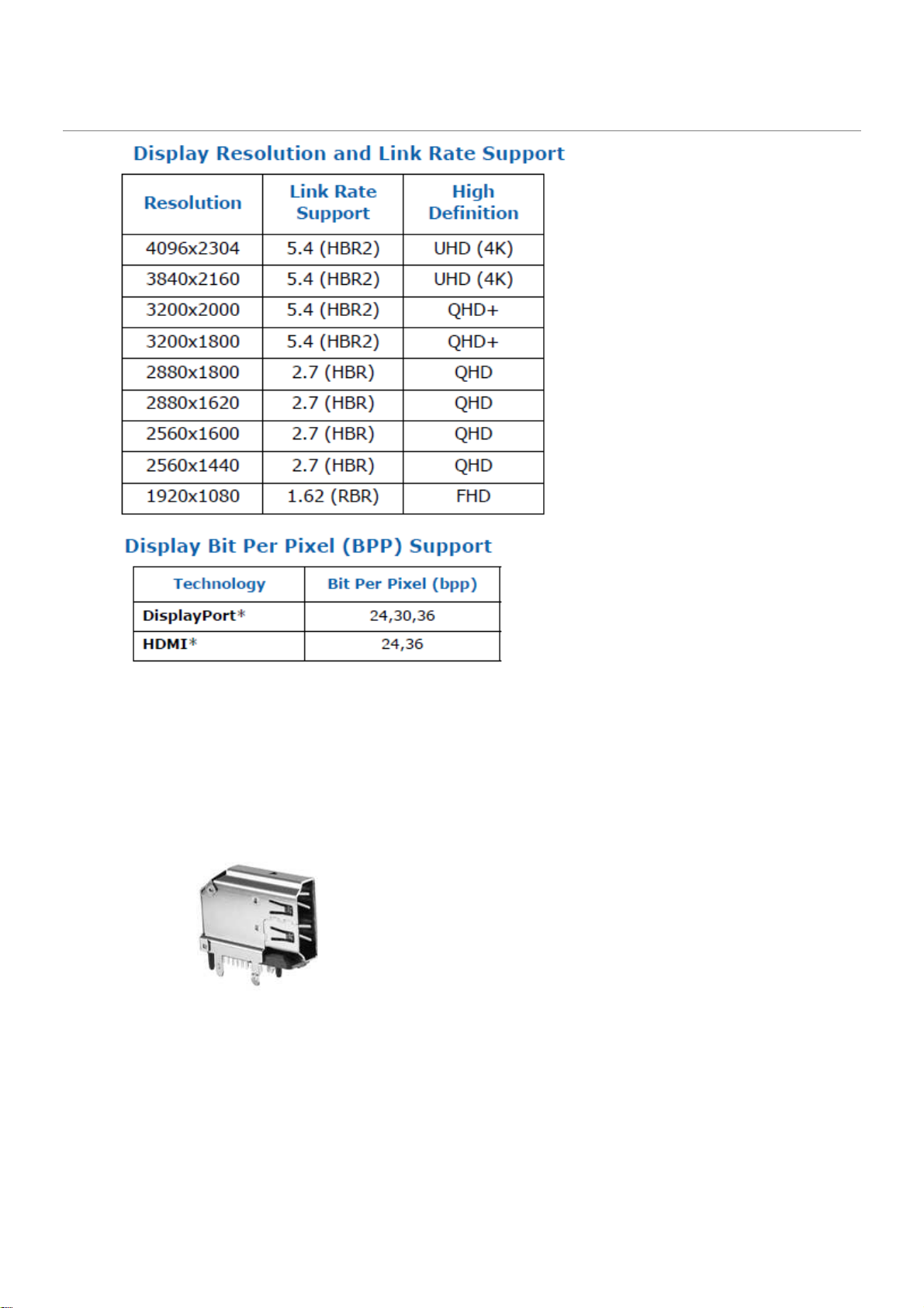
The following onboard graphics connectors must be supported when onboard graphics is enabled.
HD feature: High-Definition Multimedia Interface (HDMI*)
• HD – HDMI1.4 flush mount graphics connector: backpanel video
•
• The High-Definition Multimedia Interface (HDMI*) is provided for transmitting uncompressed digital audio
and video signals from DVD players, set-top boxes, and other audio-visual sources to television sets,
projectors, and other video displays. It can carry high-quality multi-channel audio data and all standard and
high-definition consumer electronics video formats. The HDMI display interface connecting the processor
and display devices uses transition minimized differential signaling (TMDS) to carry audiovisual
information through the same HDMI cable.
•
Page 12
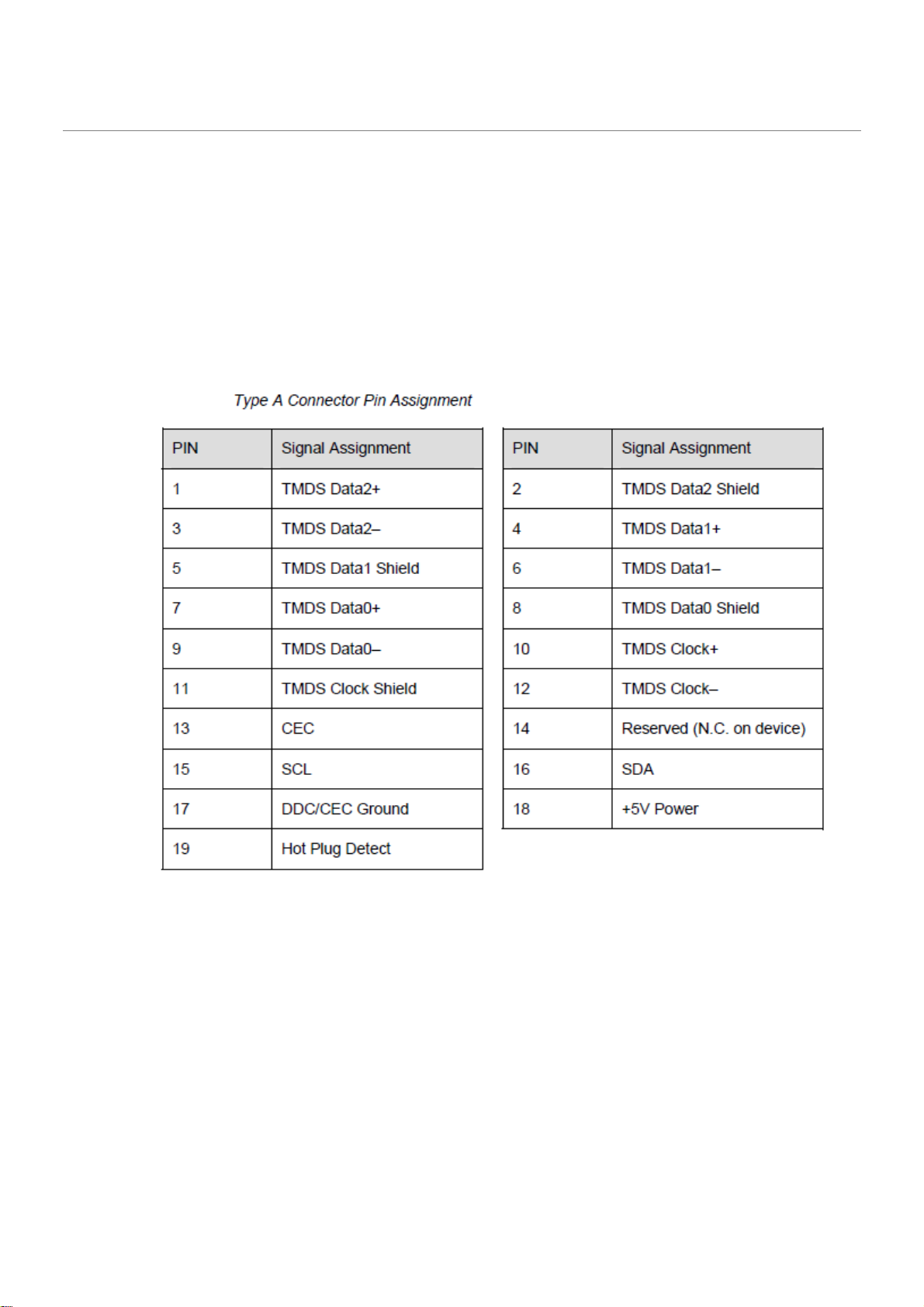
• HDMI includes three separate communications channels: TMDS, DDC, and the optional CEC (consumer
electronics control). CEC is not supported on the processor. As shown in the following figure, the HDMI
cable carries four differential pairs that make up the TMDS data and clock channels. These channels are
used to carry video, audio, and auxiliary data. In addition, HDMI carries a VESA DDC. The DDC is used by
an HDMI Source to determine the capabilities and characteristics of the Sink.
•
• Audio, video, and auxiliary (control/status) data is transmitted across the three TMDS data channels. The
video pixel clock is transmitted on the TMDS clock channel and is used by the receiver for data recovery
on the three data channels. The digital display data signals driven natively through the PCH are AC
coupled and needs level shifting to convert the AC coupled signals to the HDMI compliant digital signals.
•
• The processor HDMI interface is designed in accordance with the High-Definition Multimedia Interface.
•
Page 13
•
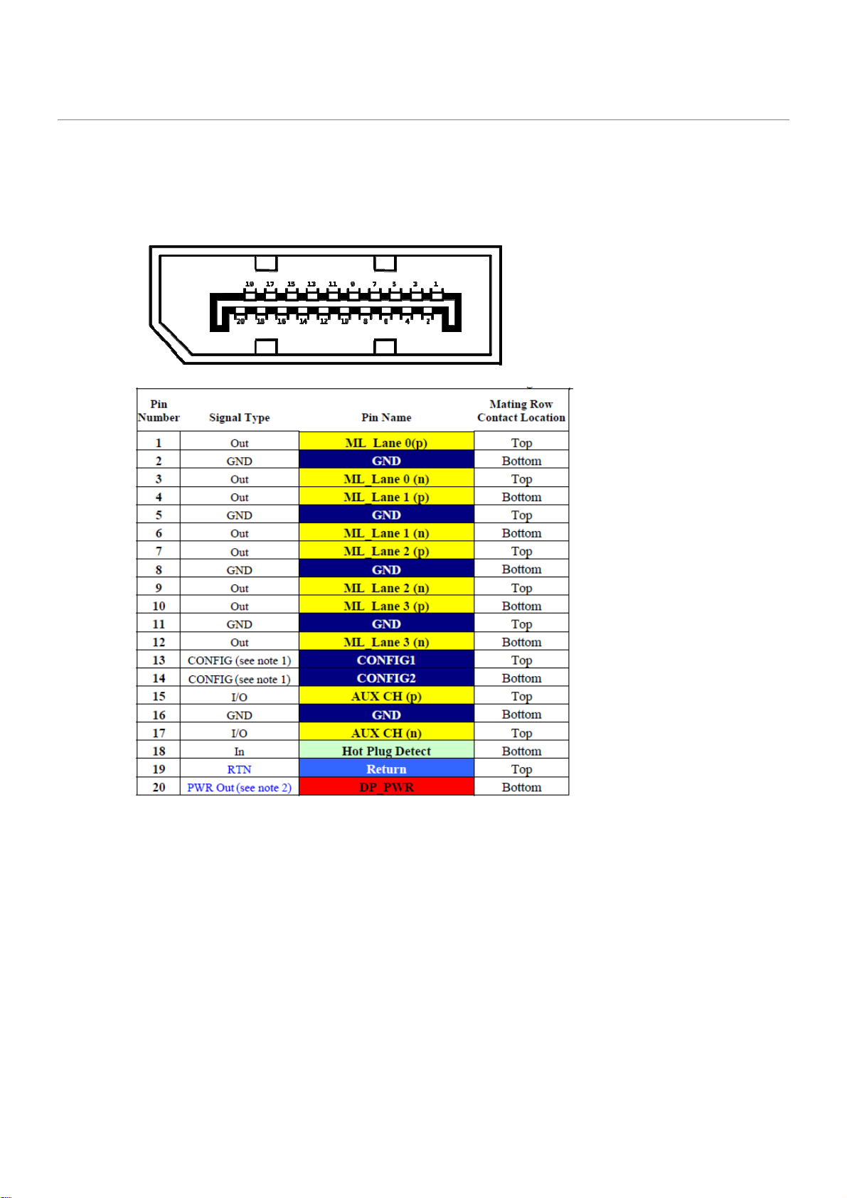
DisplayPort* feature
• Display Port: backpanel video (with embedded audio) connector for digital display support up to max
resolution allowed by the processor/PCH. Design must be Display Port v1.2 compliant and support the
following features:
•
•
o Hot-plug detect
o Display Port Interoperability - to allow use of a Display Port to DVI or Display Port to HDMI dongles as
described in the Shark Bay Platform Design Guide
o
Page 14
o
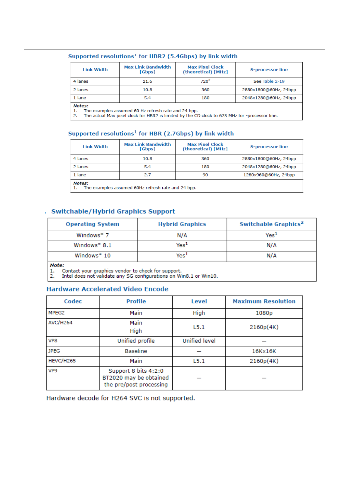
Hardware Accelerated Video Processing
There is hardware support for image processing functions such as De-interlacing, Film cadence detection,
Advanced Video Scaler (AVS), detail enhancement, image stabilization, gamut compression, HD adaptive
contrast enhancement, skin tone enhancement, total color control, Chroma de-noise, SFC pipe (Scalar
Page 15
and Format Conversion), memory compression, Localized Adaptive Contrast Enhancement (LACE),
spatial de-noise, Out-Of-Loop De-blocking (from AVC decoder), 16 bpc support for denoise/ de-mosaic.
There is support for Hardware assisted Motion Estimation engine for AVC/MPEG2 encode, True Motion, and
Image stabilization applications.
The HW video processing is exposed by the graphics driver using the following APIs:
• Direct3D* 9 Video API (DXVA2).
• Direct3D 11 Video API.
• Intel Media SDK.
• MFT (Media Foundation Transform) filters.
• Intel CUI SDK.
1.1.4 Audio
High Definition audio using 5+2 channel codec, supporting:
Implemented using the Realtek ALC662
• 3-port analog audio stack back panel connector
Board must support 3-channel audio output from the rear analog ports, with jack detection as indicated in
Table 1. An additional 2-channel analog port is required for front panel audio, with jack detection and
independent multi-streaming support for separate front vs back panel audio streams (i.e. simultaneous VoIP
and 8.1/10 audio streams).
FP Green
FP Pink
Rear Blue
Rear Green
Rear Pink
Microphone Headphones
Default
Default
(ctrl panel)
Line-Out
(Front Spks)
Line-In Rear Surr Center/Sub
Default
Default
Mic-In
(Side Surr)
Default
Table 1: Backpanel and headphone/mic front panel audio port assignments
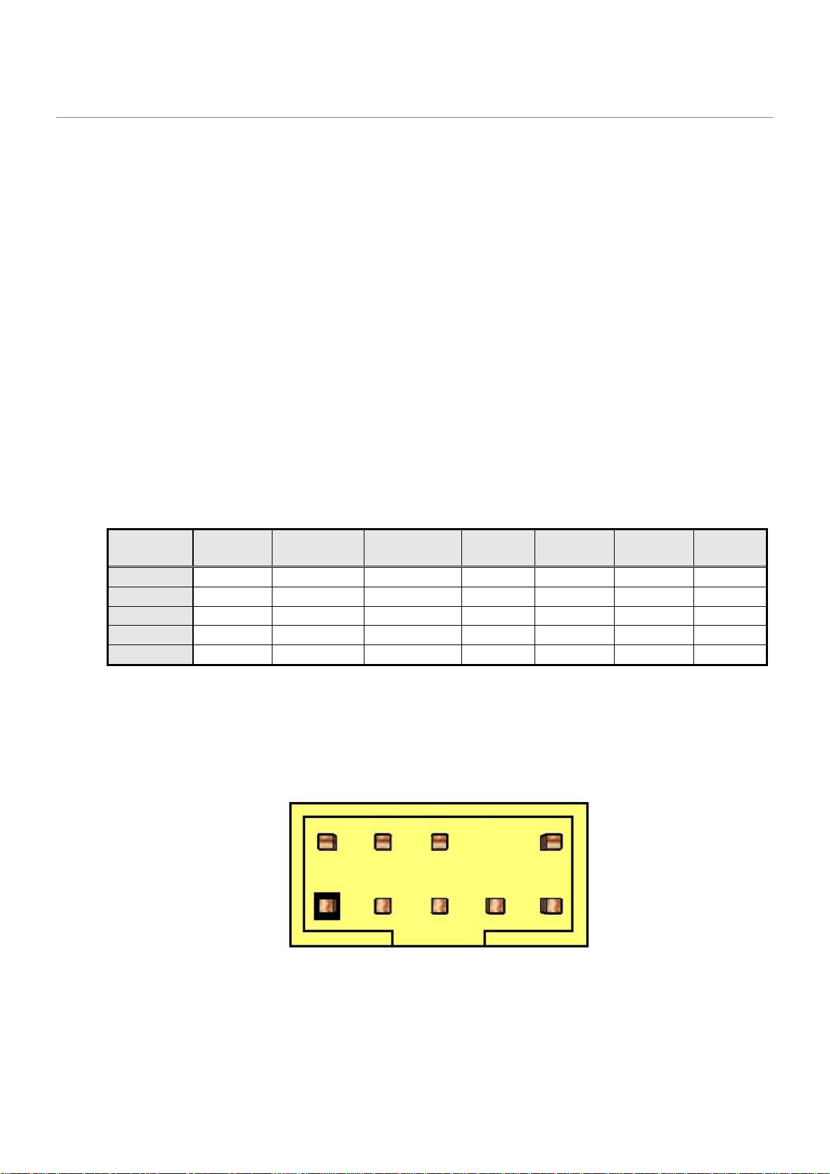
Front panel audio header must be 2x5, 2.54mm pitch, colored yellow (Pantone color code 123C) and keyed at
pin 8, as shown in Figure 2. It must be designed and validated to support both HD Audio and passive AC’97
front panel devices (AUD_5V on pin-7 is not used on passive AC’97 implementations). Passive AC'97 support
is required due to the expected large number of chassis with legacy AC'97 front panel ports. BIOS must have
the option to auto detect the front panel and provide option to enable/disable it. Connector must be shrouded.
Figure 2: Front panel audio header
Page 16
Pin Signal name Description
1 MIC
2 AUD_GND Ground used by analog audio circuits
3 MIC_BIAS Microphone power / additional MIC input for stereo microphone support
4 PRESENCE#
5 FP_OUT_R Right channel audio signal to front panel (headphone drive capable)
6 AUD_GND Ground used by analog audio circuits
7 RESERVED Reserved
8 KEY No pin
9 FP_OUT_L Left channel audio signal to front panel (headphone drive capable)
10 AUD_GND Ground used by analog audio circuits
1.1.5 LAN
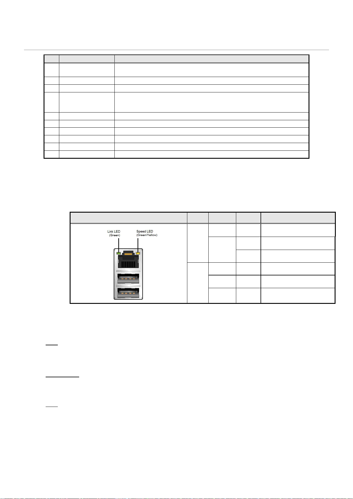
Board must implement a LAN solution supporting 10/100/1000 Mb/s with the following features:
Onboard RJ45 connectors must have integrated magnetics and support dual status LEDs per port, as shown
in Table 2.
Front panel microphone input signal (biased when supporting stereo
microphone)
Active low signal that signals BIOS that an Intel® HD Audio dongle is
connected to the analog header. PRESENCE# = 0 when an Intel® HD
Audio dongle is connected.
Note: LAN subsystem must be tested for IEEE802.3 conformance on each port.
1.1.6 SATA
SATA Gen 3
Board must also support the following Serial ATA Gen 3 compliant ports driven by the PCH:
•
Six (6) fully-shrouded right angle internal SATA gen 3 ports (colored blue Pantone 285C)
Diagram LED Color State Condition
N/A Off LAN link is not established
Link
Green
N/A Off 10 Mb/s data rate
Speed
Green On 100 Mb/s data rate
Yellow On 1000 Mb/s data rate
On LAN link is established
Blinking LAN activity occurring
Table 2: RJ45 LED behavior
Note: All SATA must be compliant with the Serial ATA Revision 3.0 Specification, as noted in the Reference
Documentation section.
1.1.7 Super I/O
Board must support the following features through a SuperIO controller device:
•
PECI support for CPU Temp
Page 17
LAN
Audio
LINE_IN_C
COM P2
USB USB2
USB3
Audio
FRONT_E
COM P1
USB DisplayPort(1)
HD USB2
USB3
Audio
MIC_IN_D
•
SMBUS/SMLink support for PCH temp
•
Support for as many fan headers as required in section 1.4.2 - Fan Header Requirements
•
Support minimum of 2 temperature inputs per PWM Controller for duty cycle determination
•
Support for non-ACPI based fan control (thermal responsiveness independent of system software)
•
Power sequencing and motherboard glue logic
•
Legacy I/O (for applicable ports)
•
Deep Sleep glue logic
1.2 Expansion I/O
1.2.1 Back Panel I/O
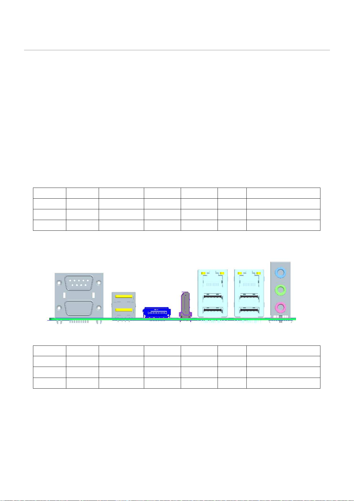
Backpanel must be designed with horizontal keepout space between ports exceeding specifications for ease
of cable connectivity/removal. A minimum of 2 mm between cable connectors is required when all ports are
being used with commonly available “off-the-shelf” cables.
Board must have a back panel layout similar to Figure 3, 5:
LAN LAN Audio LINE_IN_C
COM P2 USB USB3 USB3 Audio FRONT_E
COM P1 USB DisplayPort(1)
Figure 3: Q170 Back panel layout
1) Supported but not stuffed on production boards
HD USB3 USB3 Audio MIC_IN_D
Figure 5: H110 Back panel layout
Page 18
1 Vbus
Power
5 IntA_P1_SSTX
- USB3 ICC Port1 SuperSpeed Tx
-
1.2.2 USB
Board must support the following Universal Serial Bus ports:
Port Summary
•
10 total USB2.0 Ports (4 back-panel, 6 internal)
•
4 total USB 3.0 Ports (2 back-panel / 2 internal)
Implementation Details:
•
2 USB v2.0 ports via the back-panel
•
4 USB v3.0 ports via the back-panel
•
2 USB v2.0 ports via 1 dual-port internal headers for front panel cabling
•
2 USB v3.0 ports via 1 dual-port internal headers for front panel cabling
Header must be placed on the lower edge of the board near the 2x12 power header near
uATX mounting hole ‘L’
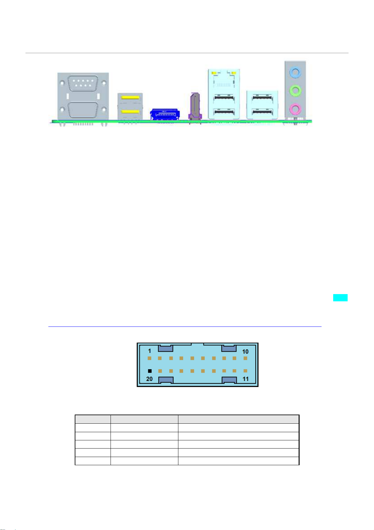
Front panel USB3 header must be 2x10 shrouded, 2.00mm pitch, colored light blue (Pantone color code 298C)
and keyed at pin 20, as defined in Table 3 and shown in Figure6. USB 3.0 Internal Connector and Cable
Specification can be found at:
http://download.intel.com/technology/usb/USB_3.0_Internal_Connector_and_Cable_Specification.pdf
Figure6: Front Panel USB 3.0 header
Page 19
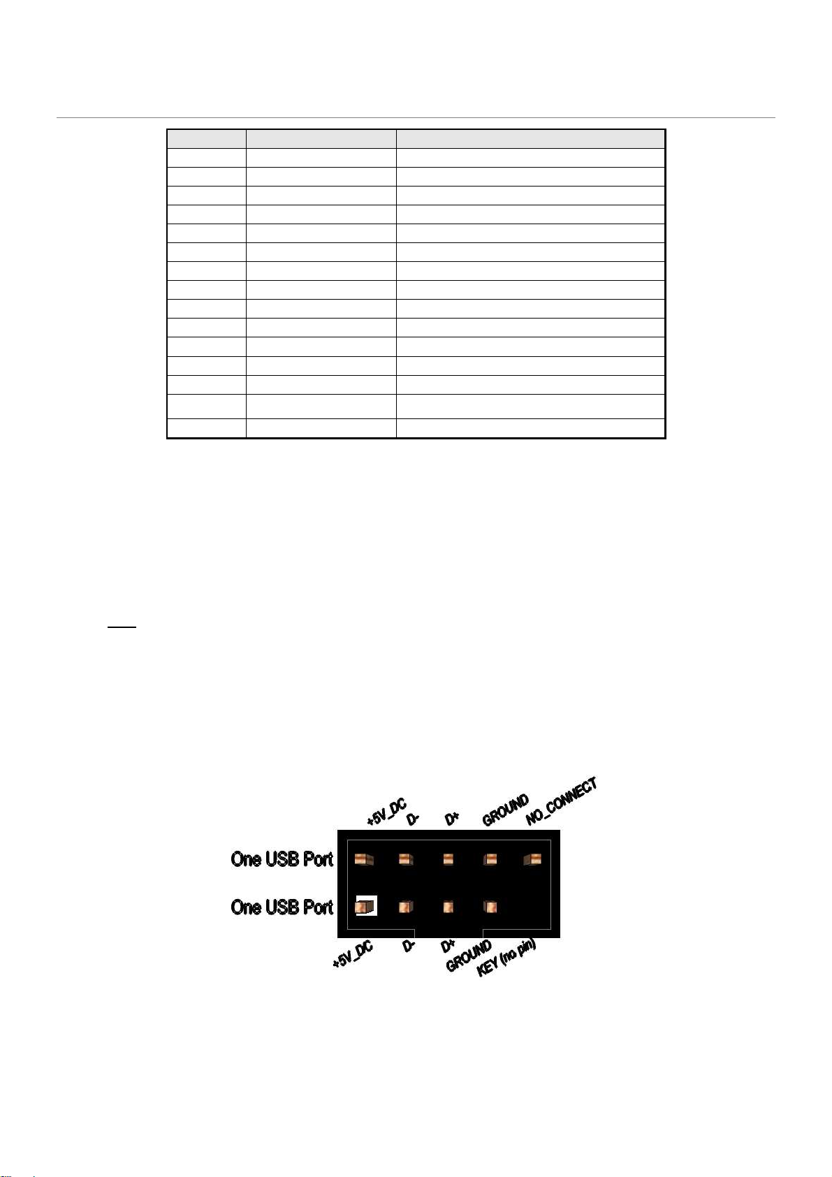
6 IntA_P1_SSTX+
USB3 ICC Port1 SuperSpeed Tx+
7 GND Ground
8 IntA_P1_D
- USB3 ICC Port1 D
- (USB2 Signal D
-)
9 IntA_P1_D+
USB3 ICC Port1 D
- (USB2 Signal D+)
10 ID Over Current Protection
11 IntA_P2_D+
USB3 ICC Port2 D+ (USB2 Signal D+)
12 IntA_P2_D
- USB3 ICC Port2 D
- (USB2 Signal D
-)
13 GND Ground
14 IntA_P2_SSTX+
USB3 ICC Port2 SuperSpeed Tx+
15 IntA_P2_SSTX
- USB3 ICC Port2 SuperSpeed Tx
-
16 GND
Ground
17 IntA_P2_SSRX+
USB3 ICC Port2 SuperSpeed Rx+
18 IntA_P2_SSRX
- USB3 ICC Port2 SuperSpeed Rx
-
20 Key Not Connected
19
Vbus Power
Table 3: Front Panel USB3.0 header signal
Front panel USB header must be 2x5 fully shrouded, 2.54mm pitch, colored black and
keyed at pin 9, as
Blue color for all USB3 back-panel ports must be Pantone color code 300C.
Board must support BIOS option to leave back-panel USB2 ports enabled during low-power states so as to
power peripherals when in S3/S4/S5.
Note: Footprint for back-panel USB/PS2 combo-jack must also allow dual-port USB stack only, shall future
SKU revision require such stuffing option.
Refer to “Back Panel I/O” section for preferred back-panel USB layout implementation.
Each port, whether on the back panel or internal header, must have its own address space so that individual
port disabling can be performed.
Front panel USB2.0 headers must be shrouded 2x5, 2.54mm pitch, colored black and keyed at pin 9, as
defined in Figure 4 and Table 1. Follow the Intel Front Panel I/O Connectivity Design Guide for front panel
USB solutions.
Figure 4: Front panel USB header pin-out
Page 20
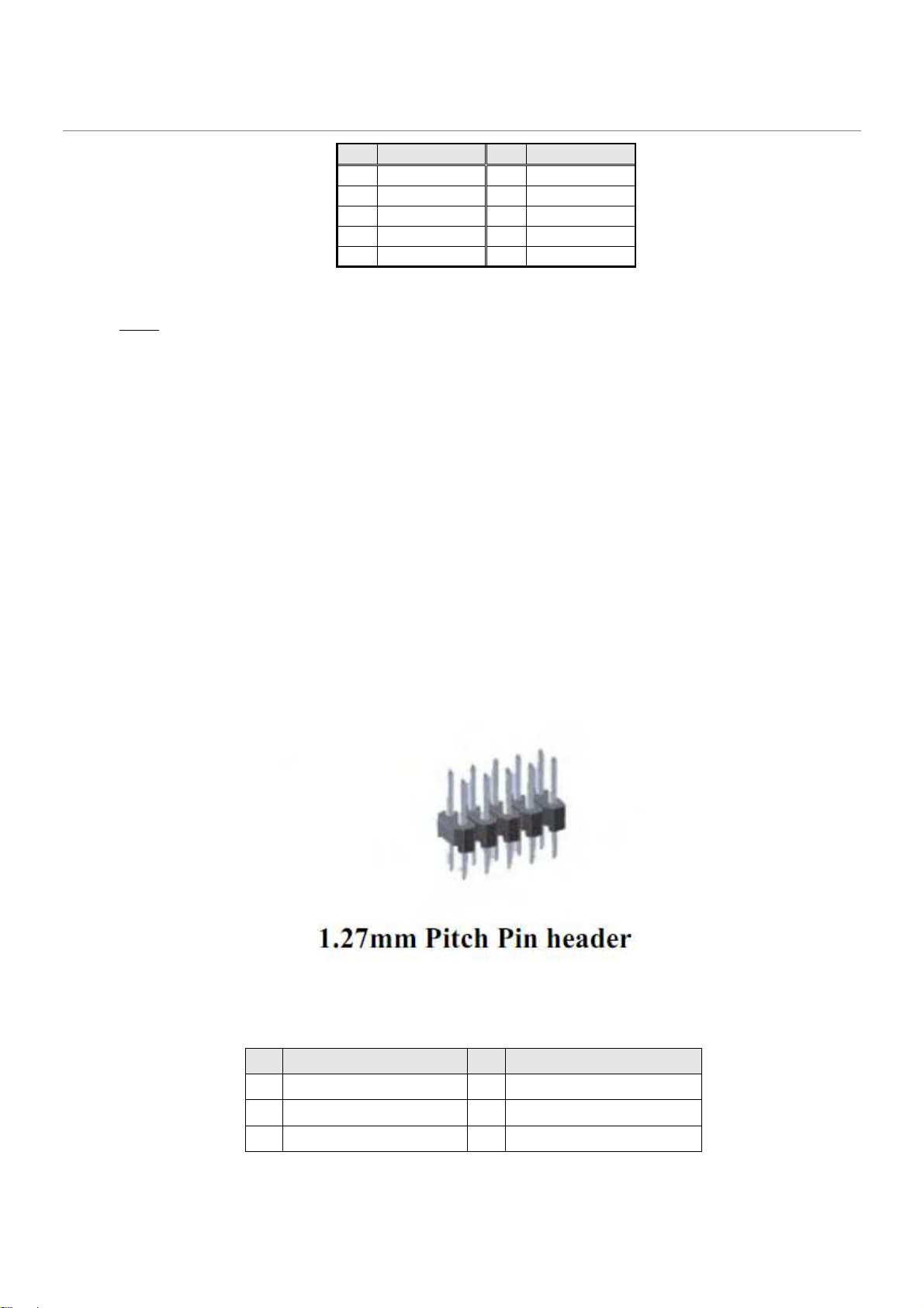
9 Key (no pin)
10
No Connect
Pin Signal Pin Signal
1 +5V DC 2 +5V DC
3 Data (negative) 4 Data (negative)
5 Data (positive) 6 Data (positive)
7 Ground 8 Ground
Table 1: Front panel USB header signals
Notes: Front panel USB headers must be placed within a keep-out-zone no smaller than 1 inch (half-inch to
the left and half-inch to the right of the header) so as to support commonly available USB connectors.
Thermistor protection is required for all back panel and front panel USB ports.
ESD protection is required for all D+ and D- signals. Signal routing/layout for all front panel and
backpanel ports must include pads for ESD protection; protection components must be stuffed. ESD
protection circuitry must meet respective signal qualification, functionality and performance.
Common mode choke footprint must be routed for all back panel and front panel USB ports (to be
stuffed on back panel ports shall EMI test fail with less than 4dB margin).
1.2.3 SPI Programing Header - None
The SPI Program Header is a default header designed by Dediprog with use with the SF100 and SF300
USBprogrammers. Can be used with the SF200 with the adapter cable.
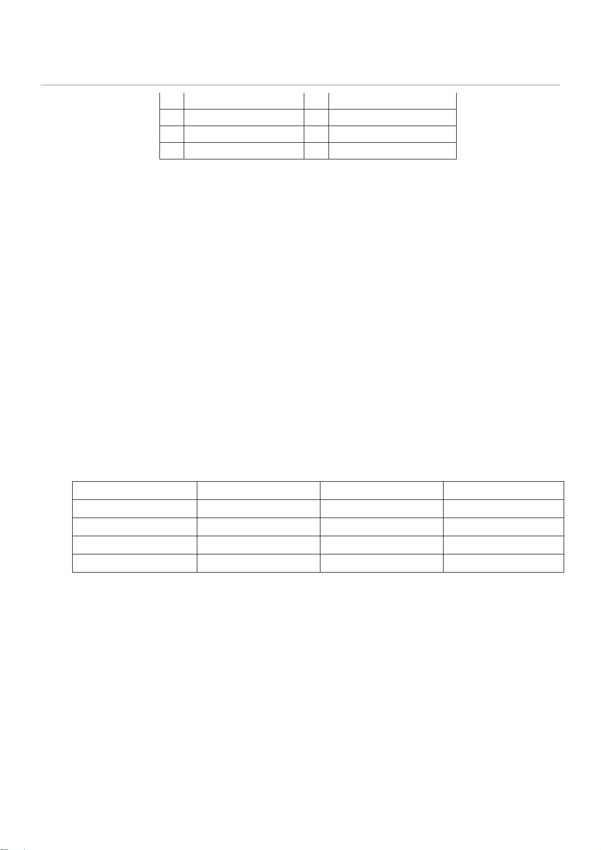
Header to be used should be a 2.54mm pitched. See Figure 7 for recommended Header.
Figure 7: SPI small format programming header
Pin LPC header signals Pin LPC header signals
1 LPC CLK 24Mhz 2 Ground
3 PLTRST#N 4 LPC FRAME#N
5 LPC Data0 6 LPC Data1
Page 21
Slot 7 (closest to CPU)
PCI E
xpress
3
.0 x1
6 X16
Blue with blue latch
7 LPC Data2 8 LPC Data3
9 Ground 10 Ground
11 VCC3 12 VCC3
13 Key (no pin) 14 VCC3
1.2.4 PCI Express Expansion Slots
Board’s PCI Express slot(s) must be PCI Express Specification v2.0 compliant and compatible with PCI
Express v2.0 and v1.1 add-in cards.
PCI Express x16 slot must be compatible with x16/x8/x4/x1 PCI Express add-on cards. PCIe x16 slot’s
retention mechanism must be consistent across Intel desktop boards.
PCI Express x4 slot(s) must be compatible with PCI Express x4 and x1 add-on cards. Slot power capability
must comply with 25W requirement as defined in the PCI Express Card Electromechanical 3.0 Specification.
PCI Express x1 slot(s) must be compatible with x1 PCI Express add-on cards.
Route WAKE# to support ACPI wake events.
Design must provide SMBus routed to all PCI Express slots, with individual/per slot de-stuffing option via
strapping resistor (strapping resistor must be stuffed by default).
Follow the ATX specification and Industrial DFA (Design for Assembly) standard requirements for connector
placement and spacing.
Keep-out zone of PCI Express v3.0 x16 slot must allow use of double-width and long graphics cards without
blocking access to any connectors (i.e. SATA ports, DIMM connector tabs, front panel audio header, …).
1.2.5 Expansion Slot Layout
Board must have the following expansion slot layout:
Slot Configuration Electrical Physical Connector Color
Slot 6 M.2 key M socket M.2 Key M socket Black
Slot 5 PCI Express 3.0 x4 X4 Black
Slot 4 PCI Express 3.0 x1 X1 Black
Notes: PCI express x16 connectors must have dual side retention latch.
M.2 Suport Socket 3 Type2280, 2260, 2242 by movable stand-off Connector Key M
1.3 Additional Headers
1.3.1 Front Panel
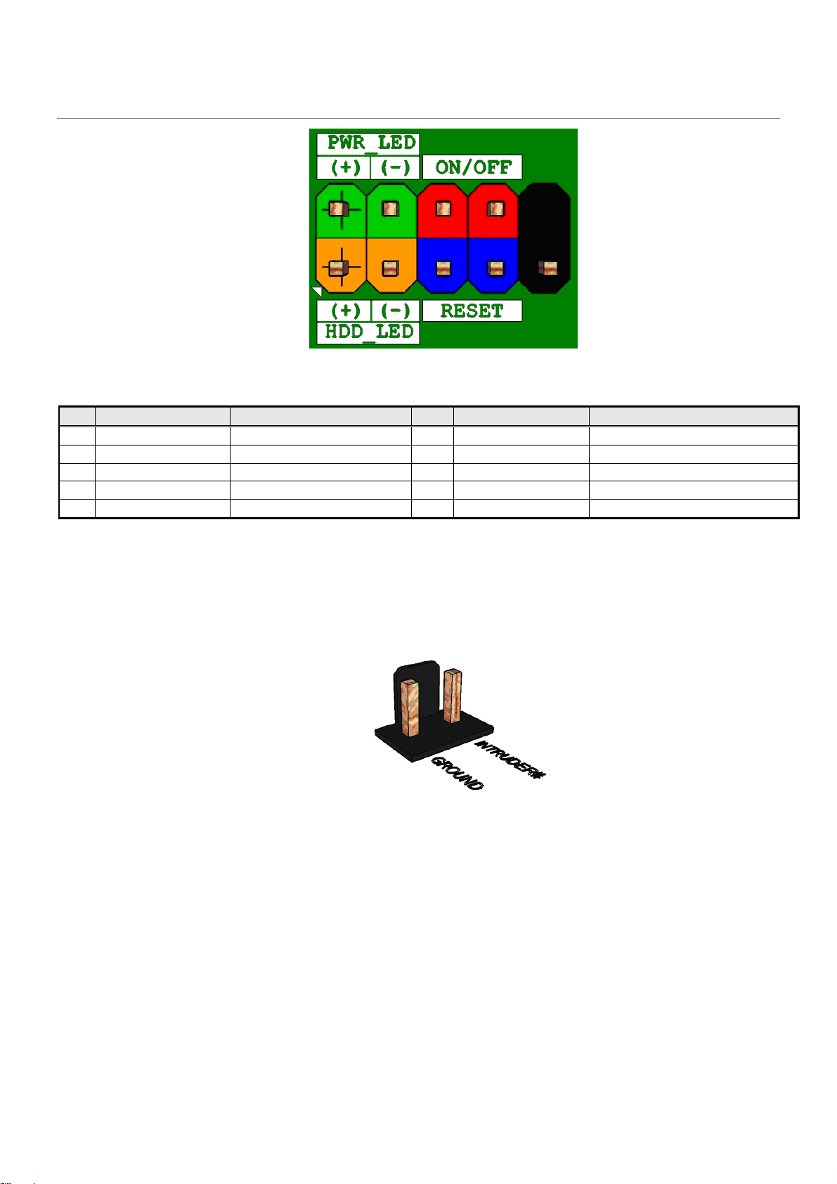
The front panel main header must be shrouded 2x5, 2.54mm pitch, multi-colored, keyed at pin 10 and with
silkscreen text as defined in Figure 8 and Table 4. Polarity markings on pins 1 & 2 and color-coding on all pins
are required. Refer to Intel PN 2100C888-121 and other Intel® Desktop Boards for front panel header
connectivity references.
Page 22
7 RESET_SWITCH#
[In] Reset switch
8
GROUND
Ground
9 +5V_DC
Power
10
KEY No pin
Figure 8: Front panel main header pin-out
Pin Signal Name Description Pin Signal Name Description
1 HDD_POWER_LED
3 HDD_LED# [Out] Hard disk activity LED 4 POWER_LED_ALT [Out] Front panel LED (alt color)
5 GROUND Ground 6 POWER_SWITCH# [In] Power switch
Pull-up resistor (750Ω) to +5V
2 POWER_LED_MAIN [Out] Front panel LED (main color)
1.3.2 Chassis Intrusion Detection
The chassis intrusion detection header must be 1x2, 2.54mm pitch, colored black and with extended back, as
defined in 9.
Figure 9 Chassis intrusion detection header
Table 4: Front panel main header signals
Page 23
6
6
1.3.3 MiAPI feature
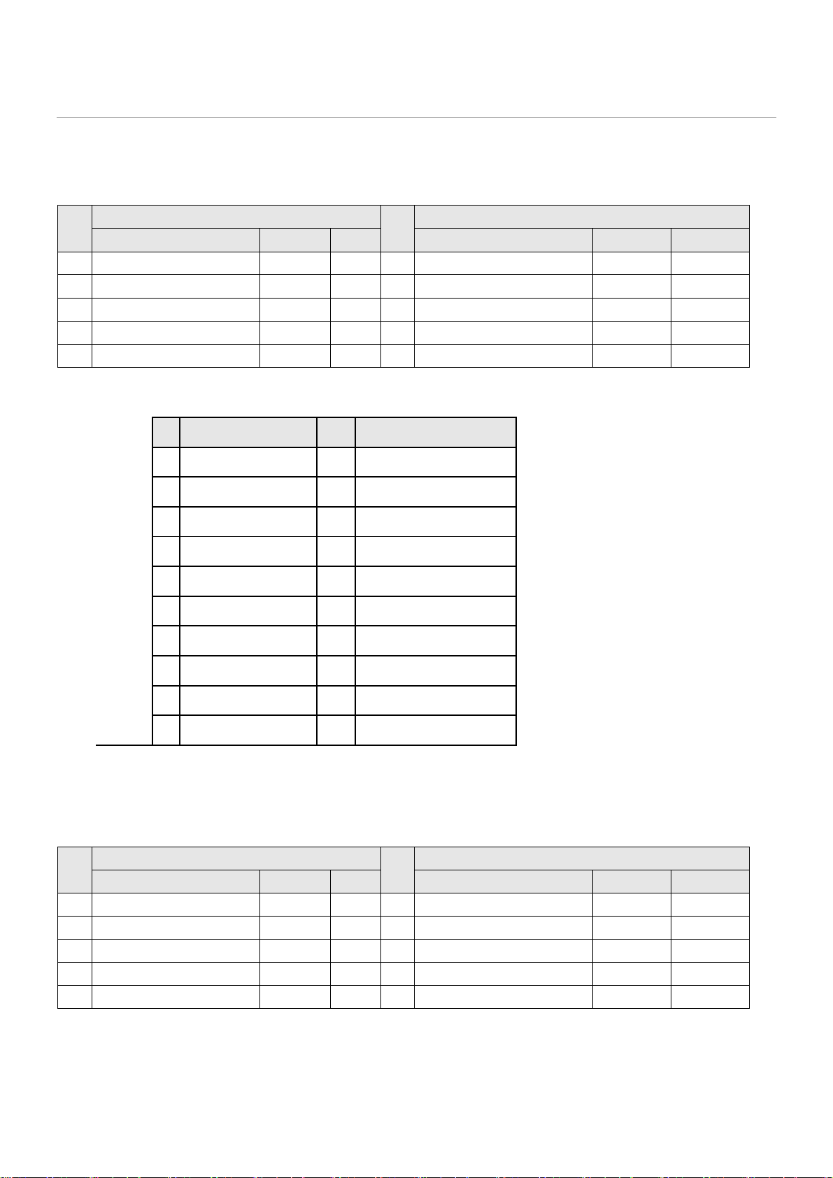
The MiAPI port header must be 2x10, 2.54mm pitch, colored black and keyed at pin 20, as defined in
Pin
RS232 RS485 RS422
1 DCD (Data Carrier Detect) R(A) / T(A) TX(B) 2 RXD# (Receive Data) R(B) / T(B) TX(A)
3 TXD# (Transmit Data) NC RX(A) 4 DTR (Data Terminal Ready) NC RX(B)
5 Ground Ground Ground
7 RTS (Request To Send) DE#/RE NC 8 CTS (Clear To Send) NC NC
9 RI (Ring Indicator) NC NC 10 Key (no pin) Key (no pin) Key (no pin)
Table 25.
Signal
Pin
RS232 RS485 RS422
DSR (Data Set Ready) NC NC
Signal
Pin Signal Name Pin Signal Name
1 MAPI_GPIO1 2 VCC
3 MAPI_GPIO2 4 MAPI_GPIO6
5 MAPI_GPIO3 6 MAPI_GPIO7
7 MAPI_GPIO4 8 MAPI_GPIO8
9 MAPI_GPIO5 10 MAPI_GPIO9
11 Watchdog Timer 12 MAPI_GPIO10
13 Power Button 14 SMB_MAIN_DATA
15 UART_TX 16 SMB_MAIN_CLK
17 UART_RX 18 5VSB
19 GND 20 N/C
Table 5: Serial port header signals
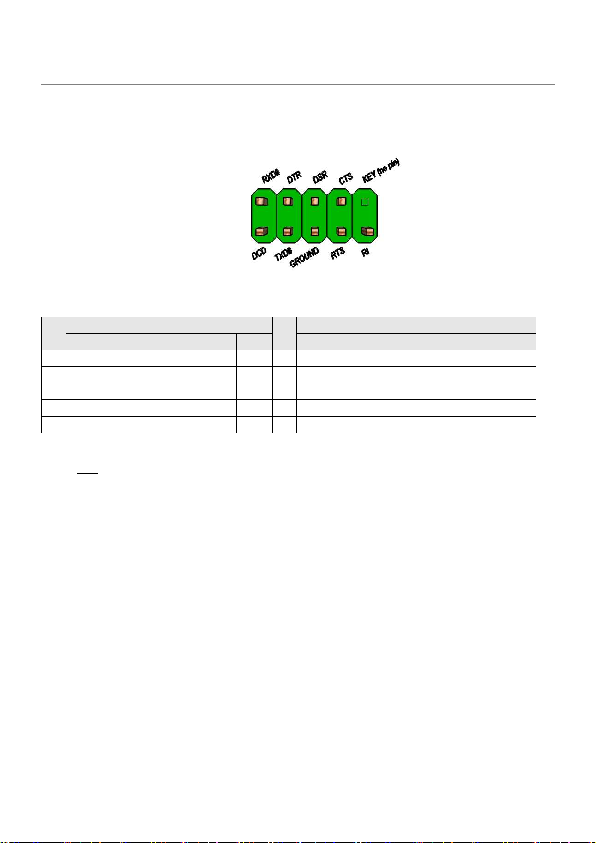
1.3.4 Serial Port
The serial port header must be 2x5, 2.54mm pitch, colored green and keyed at pin 10, as defined in Figure 0
and
Pin
RS232 RS485 RS422
1 DCD (Data Carrier Detect) R(A) / T(A) TX(B) 2 RXD# (Receive Data) R(B) / T(B) TX(A)
3 TXD# (Transmit Data) NC RX(A) 4 DTR (Data Terminal Ready) NC RX(B)
5 Ground Ground Ground
7 RTS (Request To Send) DE#/RE NC 8 CTS (Clear To Send) NC NC
9 RI (Ring Indicator) NC NC 10 Key (no pin) Key (no pin) Key (no pin)
Signal
Pin
RS232 RS485 RS422
DSR (Data Set Ready) NC NC
Signal
Page 24
6
Table 26. Header must be located around the expansion slots area to minimize port dongle cable length (most
are 4” or less).
Internal I/O header: Standart 9 pin RS232 or RS485, RS422 port
COM port 3; COM port 4
Figure 10: Serial port header pin-out
Pin
RS232 RS485 RS422
1 DCD (Data Carrier Detect) R(A) / T(A) TX(B) 2 RXD# (Receive Data) R(B) / T(B) TX(A)
3 TXD# (Transmit Data) NC RX(A) 4 DTR (Data Terminal Ready) NC RX(B)
5 Ground Ground Ground
7 RTS (Request To Send) DE#/RE NC 8 CTS (Clear To Send) NC NC
9 RI (Ring Indicator) NC NC 10 Key (no pin) Key (no pin) Key (no pin)
Pin
RS232 RS485 RS422
DSR (Data Set Ready) NC NC
Signal
Signal
Table 2: Serial port header signals
Note: The serial port header must be placed within a keep-out-zone no smaller than 1 inch (half-inch to the
left and half-inch to the right of the header) so as to support commonly available dongles.
Back Panel I/O: Standart 9 pin RS232 port and POS RS232
COM port 1; COM port 2
Page 25
DTE Signal
DTE Signal DTE Signal
DTE Signal
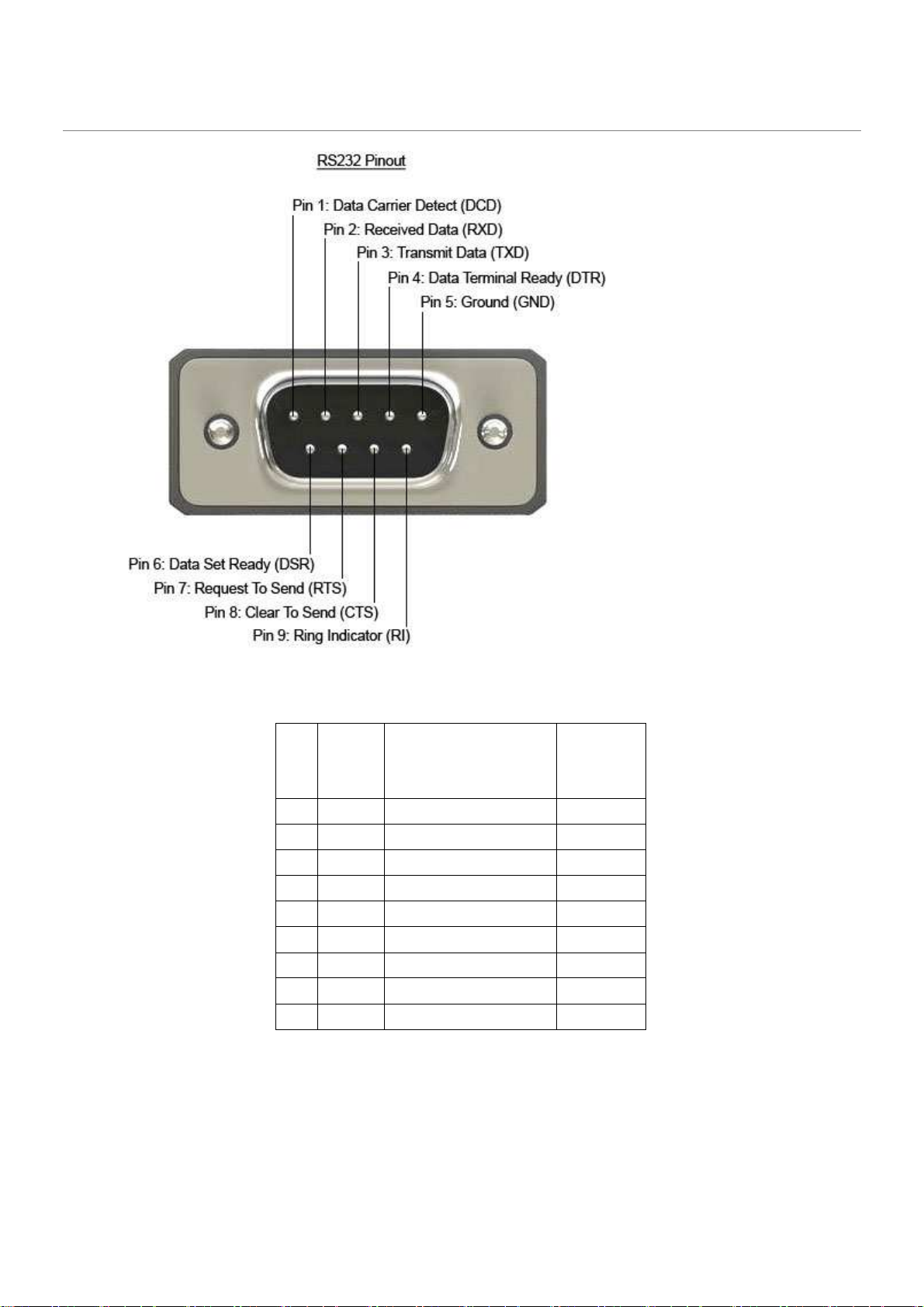
Figure 51: RS232 Serial port pin-out
Pin
Pin
Signal
PinPin
Signal
SignalSignal
Signal Name
Signal Name
Signal NameSignal Name
direction
direction
directiondirection
1 DCD Data Carrier Detect In
2 RXD Receive Data In
3 TXD Transmit Data Out
4 DTR Data Terminal Ready Out
5 GND Ground 6 DSR Data Set Ready In
7 RTS Request to Send Out
8 CTS Clear to Send In
9 RI Ring Indicator In
Table7: RS232 Serial port signals
Page 26
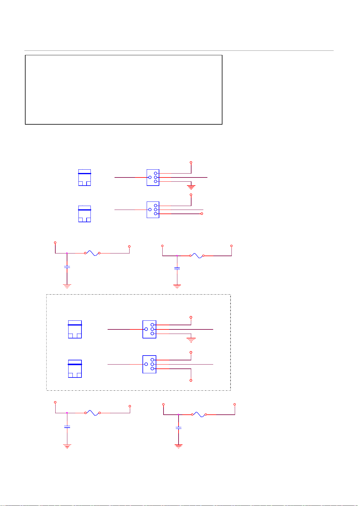
Pin1 can select 12V / GND/ RS232: NDCD at J24 and J26
Pin1 12V: J24.2<=>J24.4 J26.2<=>J26.4
Pin1 GND: J24.6<=>J24.4 J26.6<=>J26.4
Pin1 NDCD: J24.3<=>J24.4 J26.3<=>J26.4
Pin9 can select 12V/ 5V / RS232: NRI at J25 and J27
Pin9 12V: J25.2<=>J25.4 J27.2<=>J27.4
Pin9 5V: J25.6<=>J25.4 J27.6<=>J27.4
Pin9 NRI: J25.3<=>J26.4 J27.3<=>J27.4
Table8: POS RS232 Serial port signals
Power RS232 Jumper
V_12P_RS232_A
C834
10 uF
0805
X5R
16V
NA
J24(3_4)
JUMP_CAP_2P
IN
J25(3_4)
JUMP_CAP_2P
IN
F10
1.25A/15V_1812
15 V
ADC
1812
IN
NDCD1
NRI1
V_12P_ATX
J24
3
3P*2/-P1-P5
IN
J25
3
3P*2/-P1-P5
IN
V_5P_RS232_A
Power RS232 Jumper
J26(3_4)
JUMP_CAP_2P
IN
J27(3_4)
JUMP_CAP_2P
IN
V_12P_RS232_B
C838
10 uF
0805
X5R
16V
NA
F11
1.25A/15V_1812
15 V
ADC
1812
IN
NRI2
3
3
V_12P_ATX
J26
3P*2/-P1-P5
IN
J27
3P*2/-P1-P5
IN
V_5P_RS232_B
2
4
6
2
4
6
2
4
6
2
4
6
V_12P_RS232_A
COM1_P1_40mils
V_12P_RS232_A
COM1_P9_40mils
F8
C836
1.1A/6V_1206
10 uF
6V
0805
X5R
1206
16V
IN
NA
V_12P_RS232_B
COM2_P1_40milsNDCD2
V_12P_RS232_B
COM2_P9_40mils
V_5P_RS232_B
F9
C837
1.1A/6V_1206
10 uF
6V
0805
X5R
1206
16V
IN
NA
V_5P_RS232_A
V_5P_REAR
V_5P_REAR
Page 27
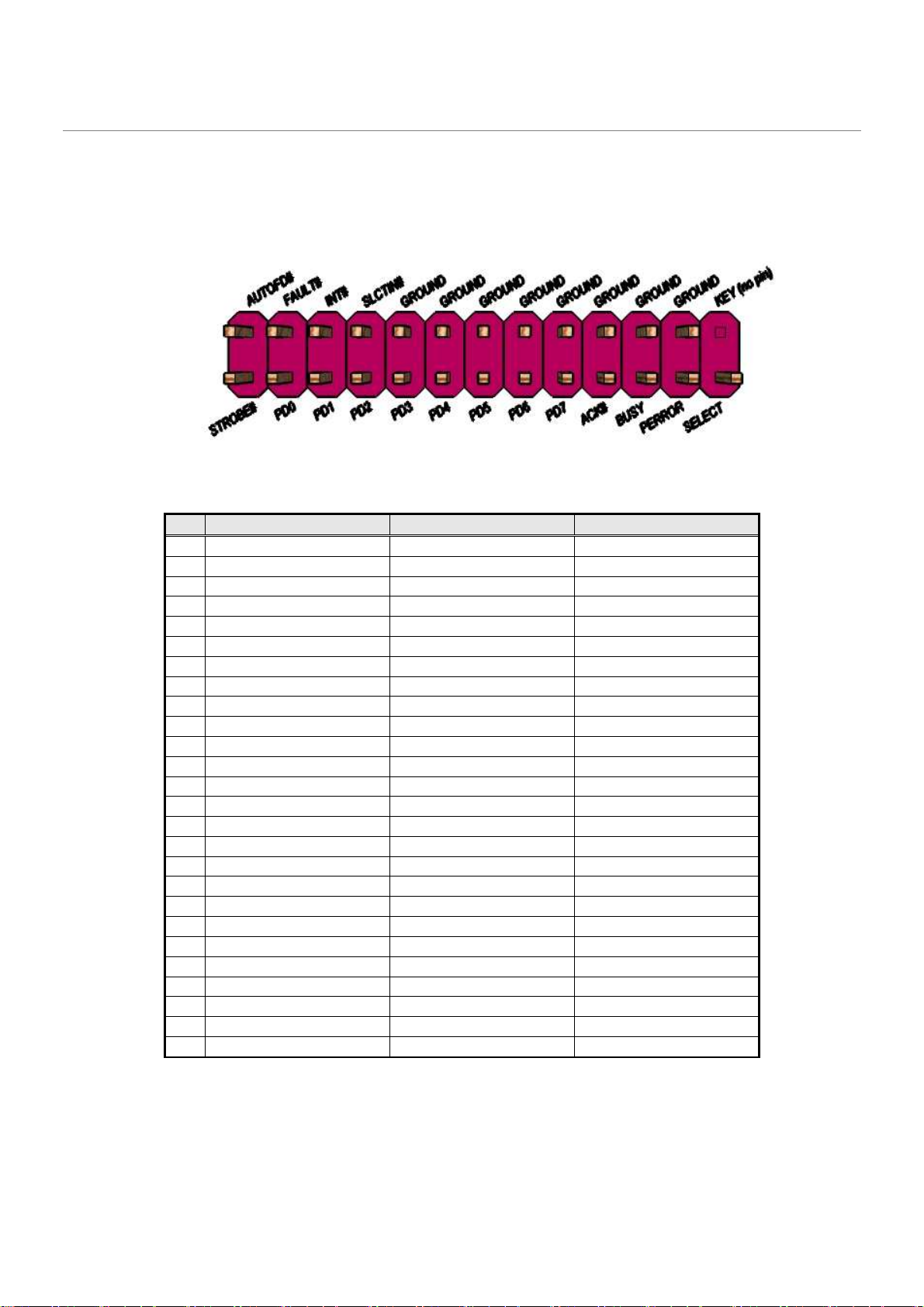
1.3.5 Parallel Port
The parallel port header must be 2x13, 2.54mm pitch, colored pink (Pantone color code “Rhodamine Red C”)
and keyed at pin 26, as defined in Figure 62 and Table9. Header must be located around the expansion slots
area to minimize port dongle cable length.
Pin Standard Signal Name ECP Signal Name EPP Signal Name
1 STROBE# STROBE# WRITE#
2 AUTOFD# AUTOFD#, HOSACK DATASTB#
3 PD0 PD0 PD0
4 FAULT# FAULT#, PERIPHREQST# FAULT#
5 PD1 PD1 PD1
6 INT# INT#, REVERSERQST# RESET#
7 PD2 PD2 PD2
8 SLCTIN# SLCTIN# ADDRSTB#
9 PD3 PD3 PD3
10 GROUND GROUND GROUND
11 PD4 PD4 PD4
12 GROUND GROUND GROUND
13 PD5 PD5 PD5
14 GROUND GROUND GROUND
15 PD6 PD6 PD6
16 GROUND GROUND GROUND
17 PD7 PD7 PD7
18 GROUND GROUND GROUND
19 ACK# ACK# INTR
20 GROUND GROUND GROUND
21 BUSY BUSY#, PERIPHACK WAIT#
22 GROUND GROUND GROUND
23 PERROR PE, ACKREVERSE# PE
24 GROUND GROUND GROUND
25 SELECT SELECT SELECT
26 KEY (no pin) KEY (no pin) KEY (no pin)
Figure 62: Parallel port header pin-out
Table 9: Parallel port header signals
Page 28
1.4 Thermal Management and Fan Control
•
Nuvoton NCT6104D SuperIO: backup alternate solution as it leverages existing hardware in the designs,
but software infrastructure must be put in place to support this solution.
Regardless of solution chosen, BIOS/driver/tools support and subsystem validation is required, even if solution
is not needed by pilot.
Board must use SuperIO solution for hardware monitoring and thermal management. SuperIO implementation
must be supported by BIOS, tools and drivers necessary for custom thermal profile management no later than
by fab B samples.
BIOS/tools/driver support and subsystem validation is required.
The thermal management capability must support temperature sensors near CPU VR FETs as well as near or
on the memory components; shall only one temperature sensor be feasible it must be located near the CPU
VR FETs.
The following thermal management features must be supported:
•
Temperature monitoring at the following locations:
o
internal thermal diode in the CPU (CPU DTS) via PECI (Platform Environmental Control Interface)
o
internal thermal diode in the PCH (PCH DTS) via SMLINK (SMBUS)
o
remote diode near CPU VR FETs
o
remote diode near or on the memory components
•
Voltage monitoring (in priority order): +12V, +5V, +5V_SB, CPU +Vccp
1.4.1 CPU and System Fans
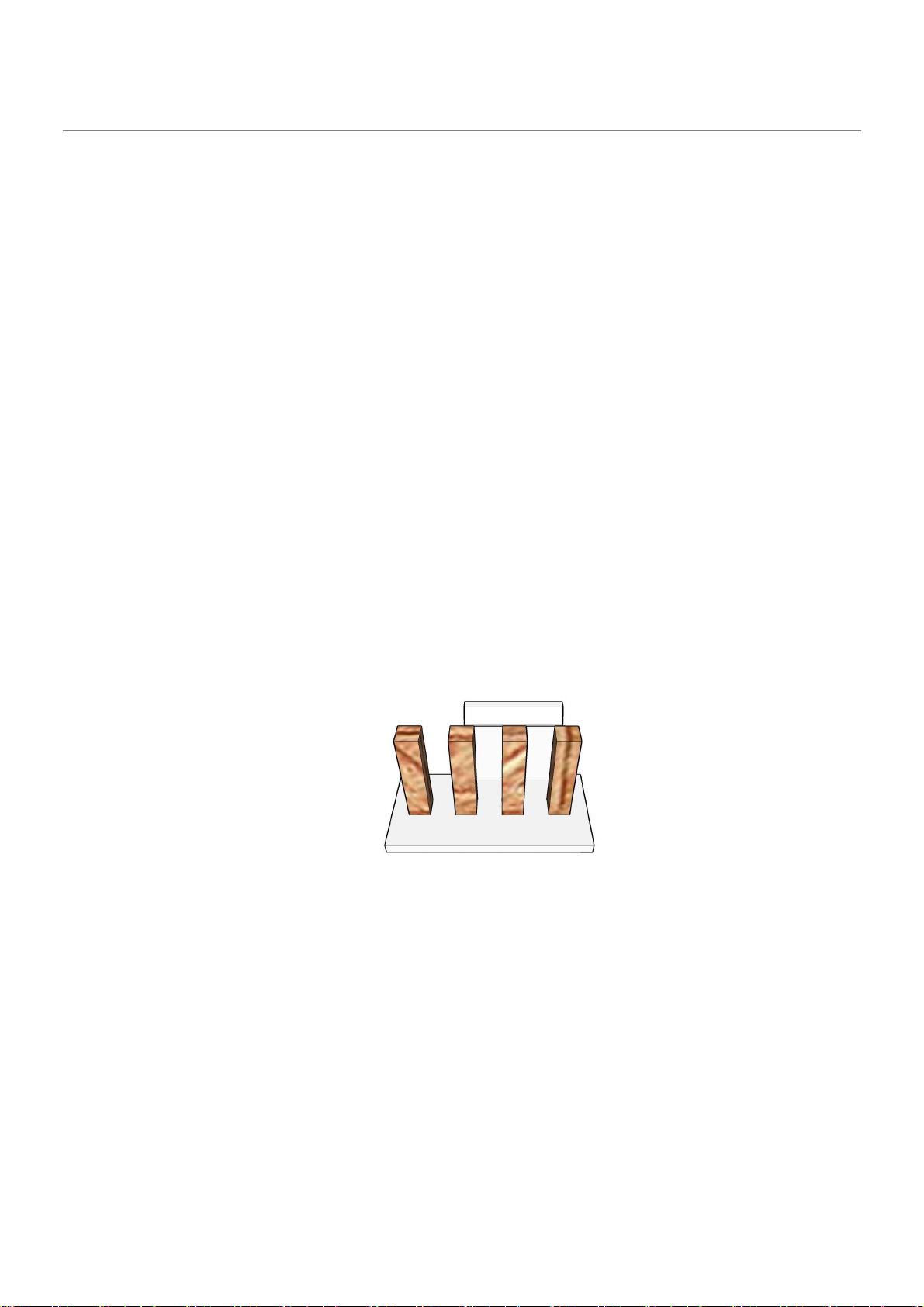
Board must implement a 4-pin fan header for the processor/heatsink 4-wire fan. Processor/heatsink fan must
be tachometer/PWM controlled and header color must be white, as shown in Figure 73.
Board must implement a 4-pin fan header for the processor/heatsink 4-wire fan. Processor/heatsink fan must
be tachometer/PWM controlled and header color must be colored red (Pantone color code 186C), as shown in
Figure 84.
Figure 73: Processor fan header
Page 29

.
1.4.2 Fan Header Requirements
The below requirements must be met for the 4-pin processor/heatsink fan (CPU FAN) header:
•
Closed loop fan speed control via the FANPWM0 signal routed to pin-4
•
Route fan tachometer signal to FANTACH0 input
•
Support 2A continuous draw
Figure 84: Front/Rear fan header
•
Clearly label as “CPU FAN”
•
Locate closest to the CPU as required by the CDPG boxed CPU
The below requirements must be met for the front fan header:
•
Closed loop fan speed control via the FANPWM1 signal routed to pin-4
•
Route fan tachometer signal to FANTACH1 input
•
Must support 1.5A continuous current draw
•
Clearly label as “FRONT FAN”
•
Locate near front edge of the board
The below requirements must be met for the rear fan header:
•
Closed loop fan speed control via the FANPWM2 signal routed to pin-4
•
Route fan tachometer signal to FANTACH2 input
•
Must support 1.5A continuous current draw
•
Clearly label as “REAR FAN”
•
Locate near back edge of the board
1.5 Silkscreen Text
Board silkscreen text must clearly label all connectors and headers with reference designators as well as userfriendly names as noted in this section.
Note: Silkscreen text shown in
There must be minimal silkscreen on the board aside from labels and logos. All silkscreen component outlines
should be removed or as minimal as possible to meet manufacturing requirements.
Courier
font for clarity.
Page 30
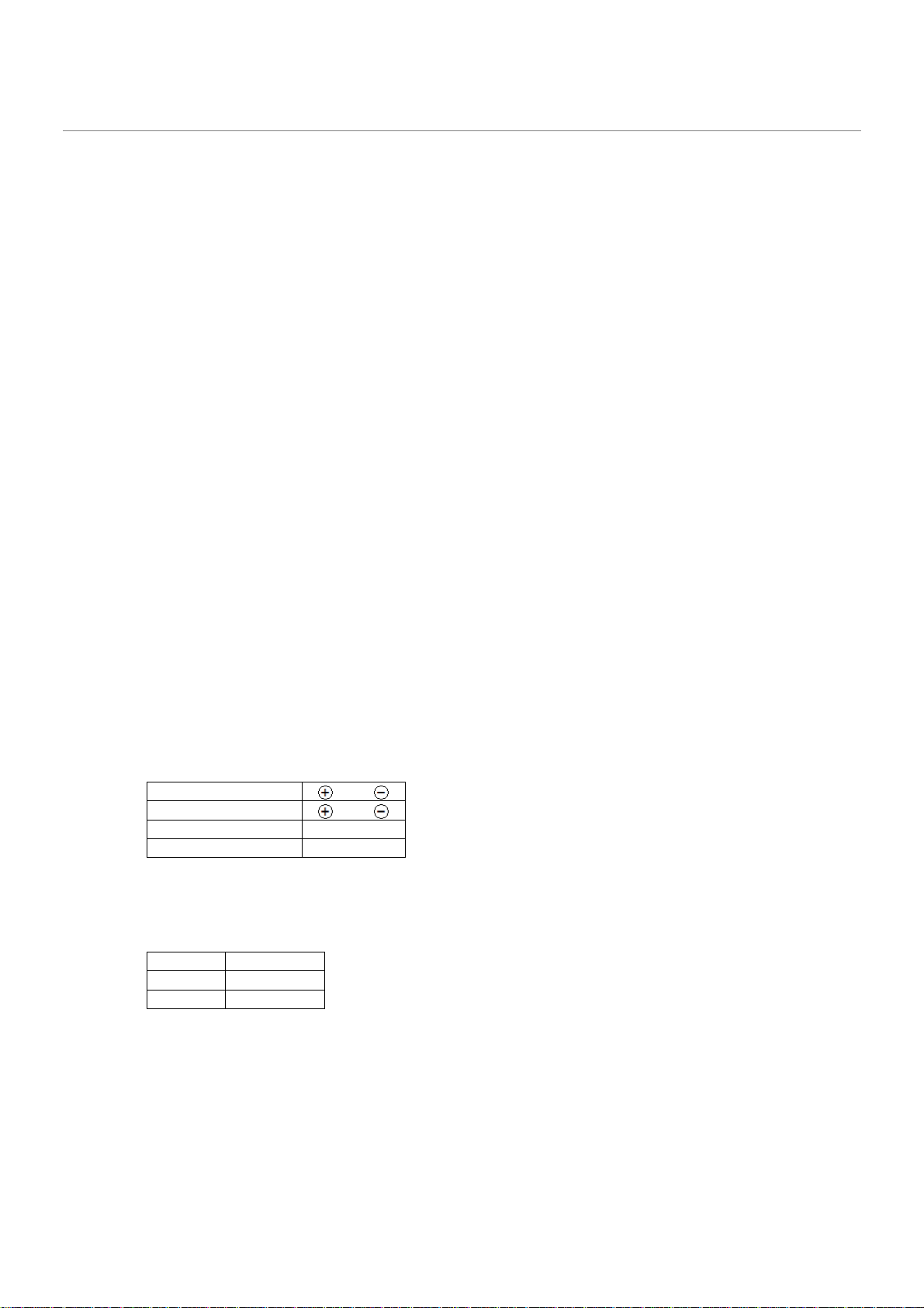
FRONT PANEL
HD LED (Orange)
1 3
PWR ON (Red)
6 8
(
J_CMOS1
)
1-2 NORMAL
Silkscreen labels should be white back-ground with clear text: .
•
ATX board must have expansion slots clearly labeled as follows:
o PCIe x16 (PCIE_X16_SLOT1)
o
PCIe M2 Key-M (J_M2_KM_1)
o
PCIe x4 (PCIE_X4_SLOT1)
o PCIe x1 (PCIE_X1_SLOT1)
•
SATA ports from PCH SATA controller must be clearly labeled:
o SATA 0 / SATADOM
o SATA 1
o SATA 2
o SATA 3
o SATA 5
•
Front panel audio header must be clearly labeled:
o FP AUDIO (J_HDA_1 location)
•
Internal IEEE1394a headers must be clearly labeled:
•
DIMM connectors must show reference designators and be clearly labeled as follows:
None
o DIMM 1
o DIMM 2
o DIMM 3
o DIMM 4
•
Fan headers must be clearly labeled as indicated in the “CPU and System Fans” section.
•
Front panel main header must be clearly labeled
FRONT PANEL
and with the clarifying pin-out text as
shown in the “Front Panel Main Header” section. The following table must also be shown nearby:
(J_FIO_1)
PWR LED (Green) 2 4
RESET (Blue) 5 7
•
Alternate Power LED must be clearly labeled:
•
BIOS configuration header must be clearly labeled
none
BIOS CFG
, with the following table shown nearby:
BIOS Config
2-3 CONFIG
NO JMP RCVRY
•
Internal USB2.0 headers must be clearly labeled:
o FP USB2.0 (FP_USB_1 location)
•
Internal USB3.0 headers must be clearly labeled:
o FP USB3.0 (FP_USB3_1 location)
•
Internal COM headers must be clearly labeled:
Page 31

o FP COM P3 (COM3 location)
o FP COM P4 (COM4 location)
•
PS/2 port header must be clearly labeled:
•
Chassis intrusion detection header must be clearly labeled:
None
o INTRD (J_INTRD1 location)
•
VR Hot LED must be clearly labeled:
•
PROCHOT LED must be clearly labeled:
•
HTPC LEDs header must be clearly labeled
•
Onboard standby LED must be clearly labeled:
o STDBY (D_STDBY1 location)
•
SPI location must be clearly labeled:
o SPI (U_SPI1 location)
None
None
None
Page 32
Page 33
Page 34
Page 35
Page 36
Page 37
Page 38
Page 39
Page 40
Page 41
Page 42
Page 43
Page 44
Page 45
Page 46
Page 47
Page 48
Page 49
Page 50
Page 51
Page 52
Page 53
Page 54
Page 55
Page 56
Page 57
Page 58

 Loading...