

Page 1

MITAC Desktop Board PD10TI
Product Guide
Page 2

1
Desktop Board Features
This chapter briefly describes the main features of MITAC Desktop Board PD10TI.
Table 1 summarizes the features of the Desktop Board.
T
AB LE
1 . F
EA TUR E SUM MAR Y
Form Factor Mini-ITX (170 millimeters [6.7 inches] x 170 millimeters [6.7 inches])
Processor Passively-cooled, soldered-down dual-core Intel® Atom™ processor with
integrated graphics and memory controller.
Main Memory Two 204-pin Double Data Rate 3 (DDR3) Small Outline Dual Inline
Memory Module (SO-DIMM) sockets with gold-plated contacts
Support for DDR3 1066/1333/1600 MHz SO-DIMMs (DDR3 1333 MHz
and DDR3 1600 MHz SO-DIMMs operate at1066 MHz only)
Support for up to 4 GB of system memory
Chipset Intel® NM10 Express Chipset
Integrated
Graphics
Intel® Graphics Media Accelerator 3650 (Intel® GMA 3650) integrated
graphics subsystem with support for digital video (DVI), VGA, and flat panel
displays via an LVDS display interface
External Graphics
External graphics support provided through the PCI bus connector
Audio
RealTek* ALC662 audio codec for 5.1 (6-channel) High Definition Audio (HD
Audio) and AC ’97 Audio. Included are:
Back panel audio connectors
Onboard S/PDIF digital audio header
Front panel microphone/headphone header with support for HD Audio
or AC ’97 Audio
Legacy I/O
Legacy I/O Controller (Nuvoton* W83677HG-I) that provides:
Two serial ports via onboard headers
One back panel parallel port
Hardware management support
Expansion
Capabilities
One PCI* bus add-in card connector
One PCI Express* Full-Mini Card slot with Half-Mini Card support
Peripheral
Interfaces
Seven USB 2.0 ports:
Four back panel ports
Three front panel ports (via two internal headers; one header
supports an Intel® Z-U130 USB Solid-State Drive or compatible
device
Two Serial ATA (SATA) 3.0 Gb/s connectors
Hardware Monitor
Subsystem
Hardware monitoring through the Nuvoton* W83627DH-P legacy I/O
controller, including:
Remote thermal sensor
One 3-pin system fan header with speed control
continued
Page 3

2
Tab le 1. Fe atur e Summar y (co ntinu e d)
LAN Support
Intel® 82574L Gigabit (10/100/1000 Mb/s) Ethernet LAN controller
BIOS
Support for Advanced Configuration and Power Interface (ACPI), Plug and
Play, and SMBIOS
Instantly Available
PC Technology
Support for Advanced Configuration and Power Interface (ACPI)
Wake on USB, PCI, PCI Express, LAN, serial, PS/2, and front panel
Page 4
3
Desktop Board Components
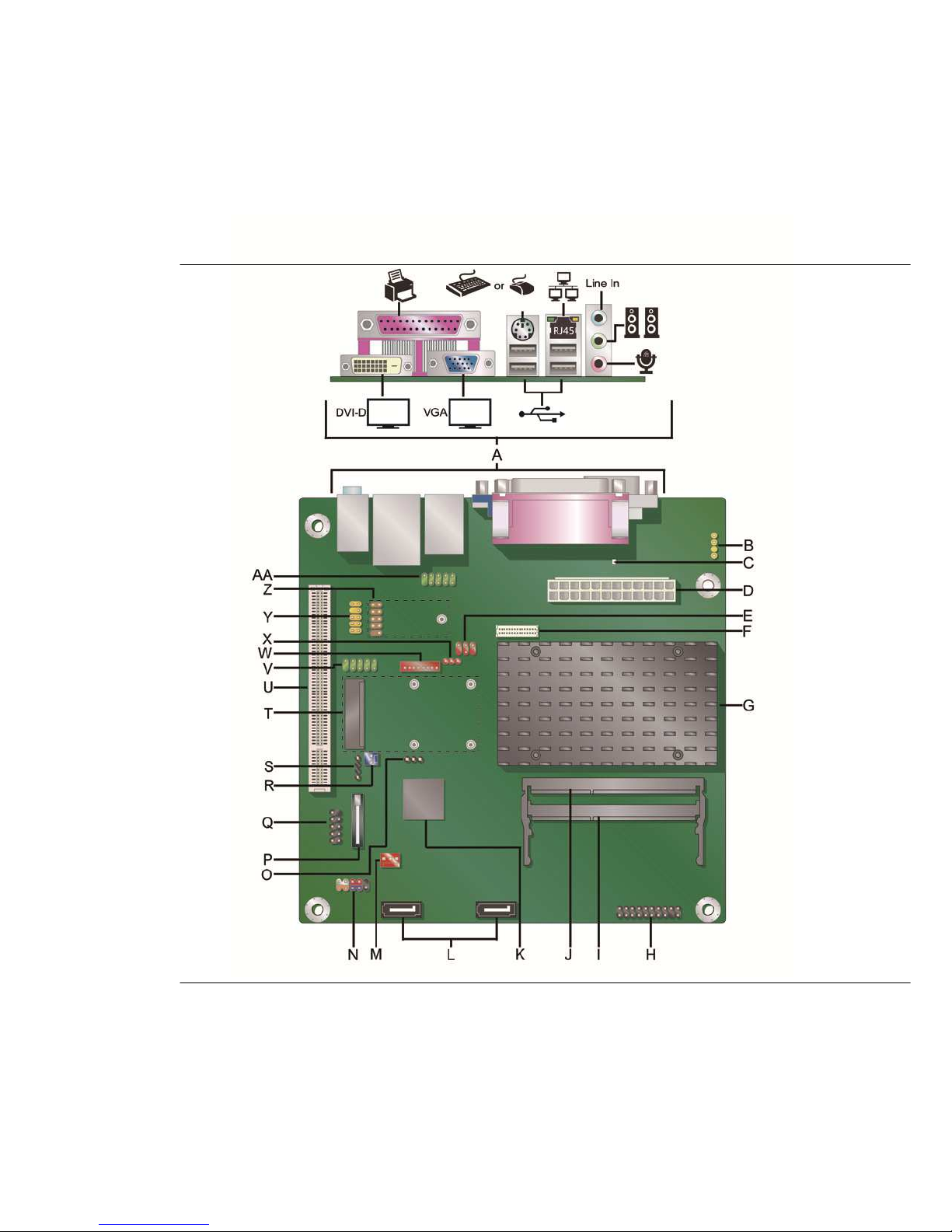
Figure 1 shows the location of the major components on MiTAC Desktop Board
PD10TI.
F
IG URE
1 . MITA C D
ES KTO P BOA RD
PD 1 0TI C
OM P ON ENT S
Page 5

4
T
AB LE
2 . MITAC D
ES KTO P BOA RD
PD 10TI C
OM PON ENT S
Label Desc ription
A
Back panel connectors
B
S/PDIF out header
C
Standby power indicator
D
Main power connector (2 x 12 pin)
E
Flat panel voltage selection header
F
LVDS interface connector
G
Processor
H
TPM header
I
SO-DIMM 1 slot
J
SO-DIMM 0 slot
K
Intel NM10 Express Chipset
L
SATA connectors
M
System fan header
N
Front panel header
O
BIOS configuration jumper block
P
Battery
Q
USB front panel header
R
Front panel wireless activity LED header
S
Piezoelectric speaker header
T
PCI Express Full-Mini Card slot
U
PCI bus connector
V
Serial port header
W
Flat panel display brightness connector
X
Backlight inverter voltage selection header
Y
Front panel audio header
Z
USB front panel header with Intel Z-U130 USB Solid-State Drive (or
compatible device) support
AA
Serial port header
Page 6

5
Processor
MiTAC Desktop Board PD10TI includes a passively-cooled, dual-core Intel Atom
processor with integrated graphics and memory controller. The processor is soldered
to the Desktop Board and is not customer upgradeable.
NOTE
The board is designed to be passively cooled in a properly ventilated chassis. Chassis
venting locations are recommended above the processor heatsink area for maximum
heat dissipation effectiveness.
System Memory
NOTE
To be fully compliant with all applicable SDRAM memory specifications, the
board should be populated with DIMMs that support the Serial Presence Detect (SPD)
data structure. If your memory modules do not support SPD, you will see a
notification to this effect on the screen at power up. The BIOS will attempt to
configure the memory controller for normal operation.
The Desktop Board has two 204-pin DDR3 SO-DIMM sockets with gold-plated contacts.
These sockets support:
Support for DDR3 1066/1333/1600 MHz SO-DIMMs (DDR3 1333 MHz and DDR3
1600 MHz SO-DIMMs operate at 1066 MHz only)
Serial Presence Detect (SPD) memory only
Non-ECC memory
Up to 4 GB of memory
Page 7
6
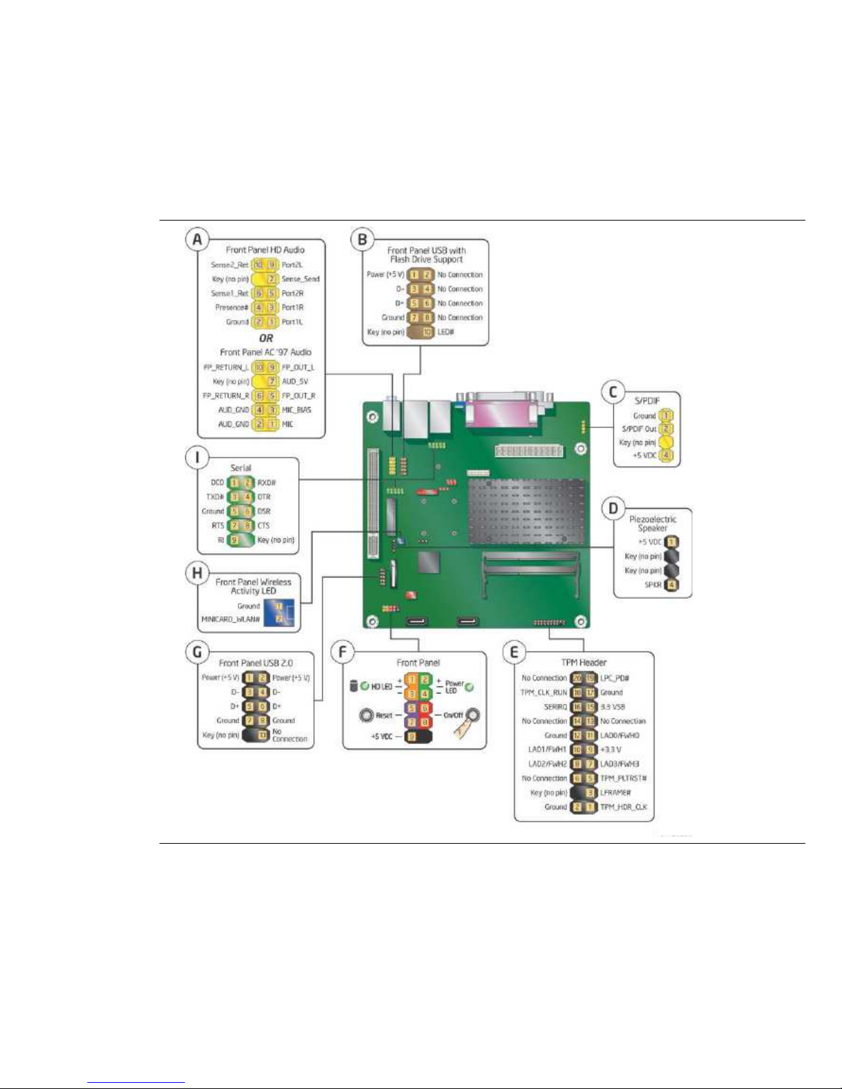
Connecting to the Internal Headers
Fi gure 2. Internal Heade r s
Page 8

7
Updating the BIOS
The BIOS Setup program can be used to view and change the BIOS settings for the
computer. You can access the BIOS Setup program by pressing the <F2> key after
the Power-On Self-Test (POST) memory test begins and before the operating system
boot begins.
This chapter tells you how to update the BIOS, and how to recover the BIOS
if an update fails.
Page 9

8
Updating the BIO S Using the F7 Function Key
To use this BIOS update method:
1. Download and save the
Recovery BIOS (.BIO) file to a temporary directory.
2. Copy the .BIO
file to a USB thumb drive.
3. Plug the thumb drive into a USB
port of the target computer.
4. Shut down the target computer.
5. Enable the F7 prompt display:
a. Power the computer on.
b. Enter the BIOS Setup by pressing the F2 key
during boot.
c. Go to the Advanced >
Boot Configuration menu.
d. Enable Display F7 to Update BIOS
e. Press
the F10 key to save and exit.
6. During boot, when
the F7 prompt is displayed, press the F7 key to enter the BIOSFlash
Update tool.
7. Select the USB
thumb drive and press Enter.
8. Select the .BIO file and press
Enter
9. Confirm you want to update the BIOS by pressing Enter.
10. Wait 2-5 minutes for the update to complete.
11. Remove the thumb drive.
12. Restart
the computer.
CAU T ION
Do not interrupt the process or the system may not function properly.
Page 10

9
NOTE
Review the instructions distributed with the update utility before attempting a BIOS
update.
CAUTION
Do not interrupt the process or the system may not function properly.
1. Uncompress the BIOS
update file and copy the .BIO file, to a bootable USB flash drive
or other bootable USB media.
2. Configure the BIOS
or use the F10 key option during POST to boot to the USB device.
CAUTION
DO NOT POWER DOWN YOUR COMPUTER before the update is complete. The update
may take up to 5 minutes.
Recovering the BIOS
It is unlikely that anything will interrupt the BIOS update; however, if an interruption
occurs, the BIOS could be damaged. Due to BIOS size and recovery requirements, a
CD-R with the .BIO file in the root directory will be required.
Page 11

10
A Board Status and Error Messages
This appendix describes status and error messages generated by the Desktop
Board’s BIOS. The BIOS indicates these error messages with front-panel Power
LED blink codes, speaker beep codes, and by displaying text on the video monitor.
BIOS Beep Codes
The BIOS uses audible beep codes to signal status messages and error messages
indicating recoverable errors that occur during the POST. The beep codes are listed
in Table 17. These beep codes can be heard through a speaker attached to the
board’s line out audio jack (see Figure 3, B on page 17) or the piezoelectric speaker
header (see Figure 12, D).
T
AB LE
3 . BIO S B
EE P COD ES
Type Pattern Frequency
BIOS update in
progress
None
Video error
(Note)
On-off (1.0 second each)
two times, then
a 2.5-second pause (off); the entire
pattern repeats (beeps and pause) once
and the BIOS will continue to boot.
932 Hz
When no VGA option
ROM is found.
Memory error
On-off (1.0 second each) three times,
then a 2.5-second pause (off); the
entire
pattern repeats (beeps and pause) until
the system is powered off.
932 Hz
Thermal trip
warning
Alternate high and low beeps (1.0 second
each) for eight beeps, followed by system
shut down.
High beep 2000 Hz
Low beep 1500 Hz
Note: Disabled by default BIOS Setup option.
Page 12

11
BIOS Front-panel Power LED Blink Codes
The BIOS also blinks the front-panel power LED to signal status messages and error
messages indicating certain recoverable errors that occur during the POST. The blink
codes are listed in Table 18.
T
AB LE
4 . BIO S F
RO NT-PA NEL POW ER
L ED B
LI NK COD ES
Type Pattern Frequency
BIOS update in
progress
Off when the update begins, then on for
0.5 second, and then off for 0.5 second.
The pattern repeats until the BIOS update
is complete.
Video error
(Note)
On-
off (1.0 second each) two times, then
a 2.5-second pause (off); the entire
pattern repeats (blinks and pause) until
the system is powered off.
When no VGA option
ROM is found.
Memory error
On-off (1.0 second each) three times,
then a 2.5-
second pause (off); the entire
pattern repeats (blinks and pause) until
the system is powered off.
Thermal trip
warning
Each beep will be accompanied by the
following blink pattern: 0.25 second on,
0.25 second off, 0.25 second on, 0.25
second off. This results in a total of 16
blinks followed by system shut down.
Note: Disabled by default BIOS Setup option.
POST Error Messages
The BIOS also displays error messages on the video monitor when certain recoverable
errors occur during the POST. Table 19 lists the error messages with a brief
description of each.
T
AB LE
5 . PO S T E
RR OR MES SAG ES
Error Message Explanation
CMOS Battery Low The battery may be losing power.
CMOS Checksum Bad
The CMOS checksum is incorrect. The CMOS memory
may have been corrupted. Run Setup to reset values.
Memory Size Decreased
Memory size has decreased since the last boot. If no
memory was removed, then memory may be bad.
No Boot Device Available System did not find a device to boot.
Page 13

12
Battery Caution
There is insufficient space on this Desktop Board to provide instructions for replacing
and disposing of the Lithium ion coin cell battery. For system safety certification, the
statement below or an equivalent statement is required to be permanently and legibly
marked on the chassis near the battery.
A suitable caution label is included with MiTAC Desktop Board PD10TI.
CAU T ION
Risk of explosion if the battery is replaced with an incorrect type. Batteries should be
recycled where possible. Disposal of used batteries must be in accordance with local
environmental regulations.
 Loading...