

Page 1

1
MSC-1610
Socket 370
w/VGA w/Dual LAN w/Audio
PCI Half-Size CPU Card
User’s Manual
MiTAC INC.
No.2, Chung-Hsiao street, Chidu, Keelung , Taiwan.
Tel : 886-2-2456-2255
Fax : 886-2-2456-9595
Part Number: : 5611M1610879 R1.1
Copyright © 2002 MiTAC INC.
Page 2

2
Copyright Notice
Copyright © 2002 by MiTAC INC.
All Rights Reserved. Printed in Taiwan.
This publication is protected by copyright and all rights are
reserved. No part or whole of it may be reproduced or
transmitted in any form or by any means, electronic or
mechanical, including photocopying and recording without prior
consent of MiTAC INC.
The information in this document has been carefully checked
and is believed to be accurate. However, MiTAC INC.. assumes
no responsibility for any errors that may appear in this document.
The material contained herein is for informational purposes only.
The information contained in this document is subject to change
without any notices.
Acknowledgments
Award is a registered trademark of Award Software International,
Inc.
IBM, PC/AT, PS/2 and OS/2 are trademarks of International
Business Machines Corporation.
Intel, Pentium and Pentium/MMX are registered trademarks of
Intel Corporation.
Windows 95/98/ Me/ 2002/ XP and Windows NT are registered
trademarks of Microsoft Corporation.
All other product names or trademarks are properties of their
respective owners.
Page 3

Contents
3
About This Manual
This manual provides information on the MSC-1610 single board
computer.
Chapter 1
provides general information, system assignment
tables, features and specifications of MSC-1610.
Chapter 2
contains dimensional drawings, jumper setting
information and connector pin assignments.
Chapter 3
describes component installations, device driver
installations, watchdog timer installation, and DiskOn Chip
installations.
Chapter 4
describes AWARD BIOS setup information, BIOS
POST code and how to update BIOS.
Page 4

Contents
4
Contents
CHAPTER 1: INTRODUCTION............................................... 1
1.1 CHECK LIST ........................................................................................... 1
1.2 FEATURES .............................................................................................. 1
1.3 SPECIFICATIONS ..................................................................................... 4
1.4 SYSTEM ASSIGNMENTS.......................................................................... 3
11..44..11 II//OO PPoorrtt AAddddrreessss MMaapp..............................................................................................................................................................3
3
11..44..22 DDMMAA CChhaannnneell AAssssiiggnnmmeennttss............................................................................................................................................4
4
11..44..33 IInntteerrrruupptt AAssssiiggnnmmeennttss..............................................................................................................................................................4
4
11..44..44 MMeemmoorryy AAddddrreessss MMaapp..............................................................................................................................................................5
5
11..44..55 SSyysstteemm TTiimmeerr MMaapp........................................................................................................................................................................5
5
CHAPTER 2: HARDWARE CONFIGURATION ................... 6
2.1 COMPONENTS LOCATION ....................................................................6
2.2 JUMPERS ................................................................................................ 7
22..22..11 CCPPUU BBaassee SSppeeeedd SSeelleecctt ((JJPP1111,, JJPP1122))............................................................................................................8
8
22..22..22 PPoowweerr SSoouurrccee ((JJPP11,, JJ44,, JJ11))............................................................................................................................................8
8
22..22..33CCOOMM22 MMooddee SSeelleecctt ((JJPP22))....................................................................................................................................................8
8
22..22..44 VVGGAA EEnnaabbllee // DDiissaabbllee ((JJPP1100))......................................................................................................................................8
8
22..22..55 LLCCDD VVoollttaaggee SSeelleeccttiioonn ((JJPP55))........................................................................................................................................8
8
22..22..66 DDiisskk OOnn CChhiipp ((MM--SSyysstteemm)) AAddddrreessss SSeelleecctt ((JJPP99))............................................................................9
9
22..22..77 WWaattcchh DDoogg TTiimmeerr ((JJPP88))........................................................................................................................................................9
9
22..22..88 RRTTCC CCMMOOSS CClleeaarr ((JJPP1100))..................................................................................................................................................9
9
22..22..99 EETTHHEERRNNEETT PPoorrtt 11 EEnnaabbllee // DDiissaabbllee ((JJPP44))..........................................................................................9
9
22..22..1100 EETTHHEERRNNEETT PPoorrtt 22EEnnaabbllee // DDiissaabbllee ((JJPP77))........................................................................................9
9
2.3 CONNECTORS....................................................................................... 10
22..33..11 SSttaannddbbyy PPoowweerr CCoonnnneeccttoorr ((JJ11))............................................................................................................................112
2
22..33..22 FFrroonntt PPaanneell CCoonnnneeccttoorr ((JJ44))......................................................................................................................................112
2
22..33..33 EExxtteerrnnaall KKeeyybbooaarrdd CCoonnnneeccttoorr ((JJ22))................................................................................................................112
2
22..33..44 UUSSBB PPoorrtt 11 ccoonnnneeccttoorr ((UUSSBB11))................................................................................................................................112
2
22..33..55 IInnffrraarreedd CCoonnnneeccttoorr ((IIRR))....................................................................................................................................................112
2
22..33..66 EExxtteerrnnaall PPoowweerr CCoonnnneeccttoorr ((PP11))..........................................................................................................................113
3
22..33..77 PPSS22 KKeeyybbooaarrdd // MMoouussee CCoonnnneeccttoorr ((KKBBMMSS))......................................................................................113
3
22..33..88 VVGGAA CCRRTT CCoonnnneeccttoorr ((VVGGAA))......................................................................................................................................113
3
22..33..99 LLCCDD CCoonnnneeccttoorr ((LLCCDD))......................................................................................................................................................114
4
22..33..1100 HHDDDD ((IIDDEE)) CCoonnnneeccttoorrss ((IIDDEE11,, IIDDEE22))..................................................................................................115
5
Page 5

Contents
5
22..33..1111 FFDDDD CCoonnnneeccttoorr ((FFDDDD))................................................................................................................................................116
6
22..33..1122 SSeerriiaall PPoorrtt 22 CCoonnnneeccttoorr ((CCOOMM22)) –– RRSS223322//442222//448855 CCoonnnneeccttoorr..............117
7
22..33..1133 CCPPUU FFaann CCoonnnneeccttoorr ((FFAANN11))................................................................................................................................117
7
22..33..1144 LLAANN PPoorrtt CCoonnnneeccttoorr ((LLAANN11//LLAANN22))..........................................................................................................117
7
22..33..1155 PPaarraalllleell PPoorrtt //CCOOMM11//UUSSBB22//AAuuddiiooCCoonnnneeccttoorr((CCNN11))........................................................118
8
CHAPTER 3: SYSTEM INSTALLING .................................. 19
3.1 INSTALLING THE DIMMS..................................................................... 20
3.2 INSTALLING THE CPU .......................................................................... 21
3.3 COMPLETING THE INSTALLATION ......................................................... 22
3.4 VIA SERVICE PACK (VIA 4IN 1).......................................................... 22
33..44..11 VVIIAA 44 iinn 11 DDrriivveerr IInnssttaallllaattiioonn PPrroocceedduurree::............................................................................................222
2
33..44..22 AAbboouutt VVIIAA 44 IINN 11 ddrriivveerrss::..............................................................................................................................................223
3
3.5 INSTALLING AUDIO DRIVER .............................................................. 24
3.6 INSTALLING VGA DRIVER .................................................................. 25
33..66..11 VVGGAA DDrriivveerr ffoorr WWiinnddoowwss 9955//9988............................................................................................................................225
5
33..66..22 VVGGAA DDrriivveerr ffoorr WWiinnddoowwss NNTT 44..00........................................................................................................................226
6
33..66..33 VVGGAA DDrriivveerr ffoorr WWiinnddoowwss 22000000..............................................................................................................................229
9
33..66..44 VVGGAA DDrriivveerr ffoorr WWiinnddoowwss XXPP....................................................................................................................................330
0
3.7 CONFIGURING ETHERNET INTERFACE ..................................................31
33..77..11 CCoonnnneecctt tthhee NNeettwwoorrkk CCaabbllee........................................................................................................................................331
1
33..77..22 MMaakkiinngg aa SSeettuupp FFllooppppyy DDiisskk....................................................................................................................................332
2
33..77..33 CCoonnffiigguurriinngg tthhee NNeettwwoorrkk aanndd IInnssttaalllliinngg tthhee DDrriivveerrss............................................................332
2
3.8 INSTALLING DISKONCHIP OF M-SYSTEMS........................................... 39
33..88..11 IInnssttaalllliinngg tthhee DDiisskk--OOnn--CChhiipp 22000000 ::................................................................................................................339
9
33..88..22 CCoonnffiigguurriinngg tthhee DDiisskkOOnnCChhiipp 22000000 aass tthhee bboooott ddeevviiccee::..................................................440
0
33..88..33 CCoonnffiigguurriinngg tthhee DDiisskkOOnnCChhiipp 22000000 aass tthhee ffiirrsstt ddrriivvee::........................................................440
0
CHAPTER 4: BIOS CONFIGURATION ............................... 42
4.1 ENTERING SETUP ................................................................................. 42
4.2 THE MAIN MENU................................................................................. 43
4.3 STANDARD CMOS SETUP ................................................................... 44
4.4 IDE PRIMARY MASTER........................................................................ 45
4.5 ADVANCED BIOS FEATURES ............................................................... 46
4.6 ADVANCED CHIPSET FEATURES ........................................................... 47
4.7 INTEGRATED PERIPHERALS .................................................................. 48
4.8 POWER MANAGEMENT SETUP ............................................................. 49
Page 6

Contents
6
4.9 PC HEALTH STATU S............................................................................. 50
4.10 FREQUENCY/VOLTAGE CONTROL ...................................................... 51
4.11 LOAD FALL-SAFE DEFAULTS.............................................................. 52
4.12 LOAD OPTIMIZED DEFAULTS ............................................................. 53
4.13 POWER ON BOOT............................................................................... 53
4.14 BIOS REFERENCE – POST CODES.................................................... 54
4.15 UPDATING BIOS................................................................................ 59
Page 7

1
C h a p t e r 1
Introduction
This chapter gives a brief introduction and provides the
specifications of the MSC-1610 Half-sized single board computer.
1.1 Check List
Before getting started, please check if your
MSC-1610package includes the following items:
MSC-1610 Socket 370 CPU board x 1pc
Driver & Utility CD x 1pc
FDD cable x 1 pc
HDD cable x 1 pc
Printer extension cable with bracket x 1 pc
Audio extension cable with bracket x 1 pc
COM1/COM2 cable with bracket x 1pc
USB extension cable. (Option)
User’s manual x 1 pc
1.2 Features
The MSC-1610 is a full featured, industrialized, half-size
single board computer with a high-frequency Intel Pentium
III
®
, or Celeron® processor (FC-PGA & FC-PGA2 package)
that brings advanced CPU technology and processing power
to the latest PCI applications. The Via Apollo Pro133T
Chipset built into the single board computer is the most
efficient and reliable way to upgrade existing PCI systems to
Pentium III technology.
Page 8

MSC-1610 User’s Manual
2
The MSC-1610 uses the PCI form factor with Socket 370 to
fit in FC-PGA and FC-PGA2 processor from Intel. The PCI
design contains one gold leaf edge connectors compatible
with PCI connectors to allow all peripherals to interface with
the processor. This lets the MSC-1610 take advantage of the
high pin density and strict electro-mechanical criteria
imposed on PCI connectors.
The MSC-1610single board computer is further enhanced by
the CHIPS 69030 Graphics Accelerator to deliver the most
advanced graphics and video support available. The 69030
supports a wide variety of monochrome and color panels,
such as: Single-Panel, Single-Drive (SS) and Dual-Panel,
Dual-Drive (DD), standard and high resolution, passive STN
and active matrix TFT LCD, and EL panels. With HiQColor
technology, up to 256 gray scales are supported on passive
STN LCDs. Up to 16.7M different colors can be displayed
on passive STN LCDs and up to 16.7M colors on 24 bit
active matrix LCDs.
The MSC-1610combines the many features needed for
system operation into one compact single board computer.
These include 10/100 TX LAN adapter, Ultra/DMA drive
controllers, high performance serial ports, enhanced parallel
port, and the latest BIOS features. Additional enhancements
to the MSC-1610 include four USB ports and a
programmable watchdog timer. Single dual in-line memory
module (DIMM) sockets support up to 512MB of
synchronous DRAM (SDRAM) memory. An internal 64-bit
second level (L2) cache supports 128/512k of memory. The
L2 cache speed is half the CPU core frequency. The Celeron
L2 cache equals 128k running at full CPU core.
Page 9

Chapter 1: Introduction
3
The VIA Apollo Pro133T chipset in the MSC-1610
incorporates the latest microprocessor technology from Intel
to provide the increased bandwidth needed to operate your
system bus at speeds up to 133MHz. (The VIA Apollo
Pro133T chipset uses one chipset for three 66MHz
100MHz and 133MHz system designed in Pentium III, and
Celeron processors with speeds of 733, 850 and 1.26 GHz.).
The VIA Apollo Pro133T chipset is a two-chip set
comprised of the VT82C694T North Bridge Controller and
the VT82C686B South Bridge Controller. PC100/133
SDRAM provide the bandwidth necessary for running
demanding software and Internet applications while
benefiting from the reliability and cost advantages of
SDRAM infrastructure. The VIA Apollo Pro133T chipset is
a PCI Rev 2.2 compliant that supports 3.3V and 5V 33MHz
PCI operations. The VIA694T chip includes Desktop Power
Management support, enhanced DMA controller and an
integrated IDE controller with Ultra DMA/100 support. In
addition, it provides USB host interface support for four
USB ports and a System Management Bus (SMB) with
support for DIMM Serial PD.
Page 10

MSC-1610 User’s Manual
4
1.3 Specifications
Processors Supported
Intel Pentium III
- FC-PGA2 133Mhz FSB (1.13GHz-1.26GHz)
- FC-PGA 100 /133MHZ (500E-1GHz)
Intel Celeron (FC-PGA & FC-PGA2)
- FC-PGA2 100MHz FSB (1AGHz- 102GHz)
- FC-PGA 66 / 100MHz (533A-1GHz)
Processor Clock Frequency and Bus Speed
66 /100 /133MHz internal frequency and bus speed
Memory Capacity
32MB minimum
512MB maximum
DIMM Support
1 DIMM, gold contacts, 168-pin
Non-ECC / ECC compatible
Memory Speed Required
64 / 72-bit SDRAM ( 66 / 100 / 133 MHz )
BIOS
Hi-Flex Pentium AWARD BIOS, Flash EPROM
support, Plug-and-Play compatible
2Mb flash upgradeable supporting BIOS upgrade via
software
Full support for Year 2000 and leap-year date functions
Page 11

Chapter 1: Introduction
5
Chipset
VIA Apollo Pro133 chipset
- VT82C694T North Bridge Controller
- VT82C696B South Bridge Controller
C&T 69030 AGP bus with Windows accelerator and
Video playback.
Display
C&T 69030 integrated 4M SDRAM for the
graphics/video frame buffer.
C&T 69000 integrated 2M SDRAM for option.
- Support 1/4 VGA, VGA, SVGA, XGA, SXGA,and
UXGA panels. It includes the Chips’ proprietary
TMED ™ technology to support 16 million colors on
STN/ DSTN panels.
-Display connector: DB-15 VGA connector for CRT
monitor and 2x20 pin header for Flat-panel
LAN Controller
Dual INTEL 82559 Ethernet controller, 10/100 Tx
with RJ-45 connector.
LAN2 for option.
EIDE Disk Controller (dual port)
Four fixed disk drives supported (two each on primary
and secondary)
PIO Mode 4 and Ultra DMA/100 supported.
Full support for LS-120 HD floppy drive.
Floppy Diskette Controller (dual port)
Support 2.88MB,1.44MB/720KB and 1.2MB/360KB
floppy drives.
Page 12

MSC-1610 User’s Manual
6
Serial Ports
One RS232, 16C550-compatible, FIFO buffer
One RS-232/RS-422/RS-485 selectable
Parallel Port
Single parallel port controller with bi-directional
compatibility
EPP and ECP enhanced port modes.
PS/2 Keyboard and Mouse port
Microsoft compatible
6-pin mini-DIN connector at rear panel
Power supplied through +5VDC self-healing fuse
Universal Serial Bus (USB)
Universal Host Controller Interface (UHCI)
configuration
Four USB connectors at rear panel via separate cable
and bracket assembly (optional)
Power supplied through +5VDC self-healing fuse
Sound
AC’97 supported with full duplex, independent sample
rate converter for audio recording and playback
Watchdog Timer
Reset CPU automatically if CPU stops operating
Reset CPU automatically if +5VDC varies more than
10%
Jumper or software disable/enable
Page 13

MSC-1610 User’s Manual
2
Disk On Chip of M-system
Support one Single Chip Flash Disk in 32Pin DIP
JEDEC socket.
Real-time Clock
SGS-THOMSON M48T86MH1 compatible
256 bytes of battery-backed RAM
On chip lithium battery with 10 years data retention.
Operating Environment
Temperature: 0 to 55 °C
Humidity: 5 to 90% RHNC
Storage Environment
Temperature: -40 to 85 °C
Humidity: 10 to 90% RHNC
Power Requirements
+5V and +12V
Notes: 1) +5V current draw is processor dependent.
2) Onboard +3.3 V is regulated down from the +5V source.
Page 14

Chapter 1: Introduction
3
1.4 System Assignments
1.4.1 I/O Port Address Map
Address
( HEX )
Device
000-01F DMA controller 1
020-021 Interrupt controller 1
040-05F Timer 1 & 2
043 Disable Watch-dog timer operation (read)
060-06F Keyboard controller
070-07F Real Time Clock, Non_Maskable interrupt
080-09F DMA page register
0A0-0BF Interrupt controller 2
0C0-0DF DMA controller 2
0F0 Clear math. Coprocessor busy signal
0F1 Reset math. Coprocessor
0F8-0FF Math. Coprocessor
1F0-1F8 Fixed disk controller
200-207 Game port
278-27F Parallel port #2 (LPT3)
2E8-2EF Serial port #4 (COM 4)
2F8-2FF Serial port #2 (COM 2)
300-31F Prototype card / Streaming Tape Adapter
378-37F Parallel port #1 (LPT2)
380-38F SDLC, Bisynchronous 2
3A0-3AF SDLC, Bisynchronous 1
3B0-3BF Monochrome Display, Parallel port 0 (LPT1)
3C0-3CF EGA card
3D0-3DF CGA card
3E8-3EF Serial port #3 (COM3)
3F0-3F7 Floppy Disk controller
3F8-3FF Serial port #1 (COM1)
443 Enable Watch-dog timer operation (read)
CF8-CFF Chipset Address
Page 15

MSC-1610 User’s Manual
4
1.4.2 DMA Channel Assignments
Channel Function
0 Available
1 Available
2 Floppy disk ( 8 bit transfer )
3 Available
4 Cascade for DMA controller 1
5 Available
6 Available
7 Available
1.4.3 Interrupt Assignments
Interrupt # Interrupt Source
IRQ 0 Interval timer
IRQ 1 Keyboard
IRQ 2 Interrupt from controller 2 (cascade)
IRQ 3 Serial port 2
IRQ 4 Serial port 1
IRQ 5 Parallel port 2
IRQ 6 Floppy disk controller
IRQ 7 Parallel port 1
IRQ 8 Real-time clock
IRQ 9 Cascade to controller 1 (IRQ 2)
IRQ 10 Available
IRQ 11 Available
IRQ 12 PS/2 Mouse
IRQ 13 Math coprocessor
IRQ 14 Hard disk controller (Primary)
IRQ 15 Hard disk controller (Secondary)
Page 16
Chapter 1: Introduction
5
1.4.4 Memory Address Map
Address ( HEX ) Device
0000000-009FFFF System memory
00A0000-00BFFFF Display memory
00C0000-00C7FFF VGA BIOS ROM
00C8000-00EFFFF I/O device BIOS ROM or RAM buffer
00F0000-00FFFFF System BIOS ROM
0100000-BFFFFFF System extension memory
1.4.5 System Timer Map
Timer # Assignment
1 System timer interrupt
2 DRAM Refresh Request
3 Speaker tone generator
Page 17

Page 18
6
C h a p t e r 2
Hardware Configuration
This chapter explains how to properly set the jumpers and
how to use the connectors of MSC-1610.
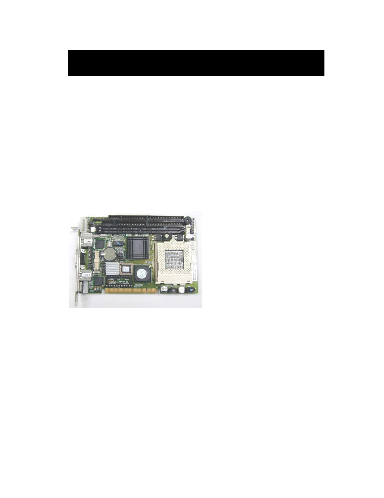
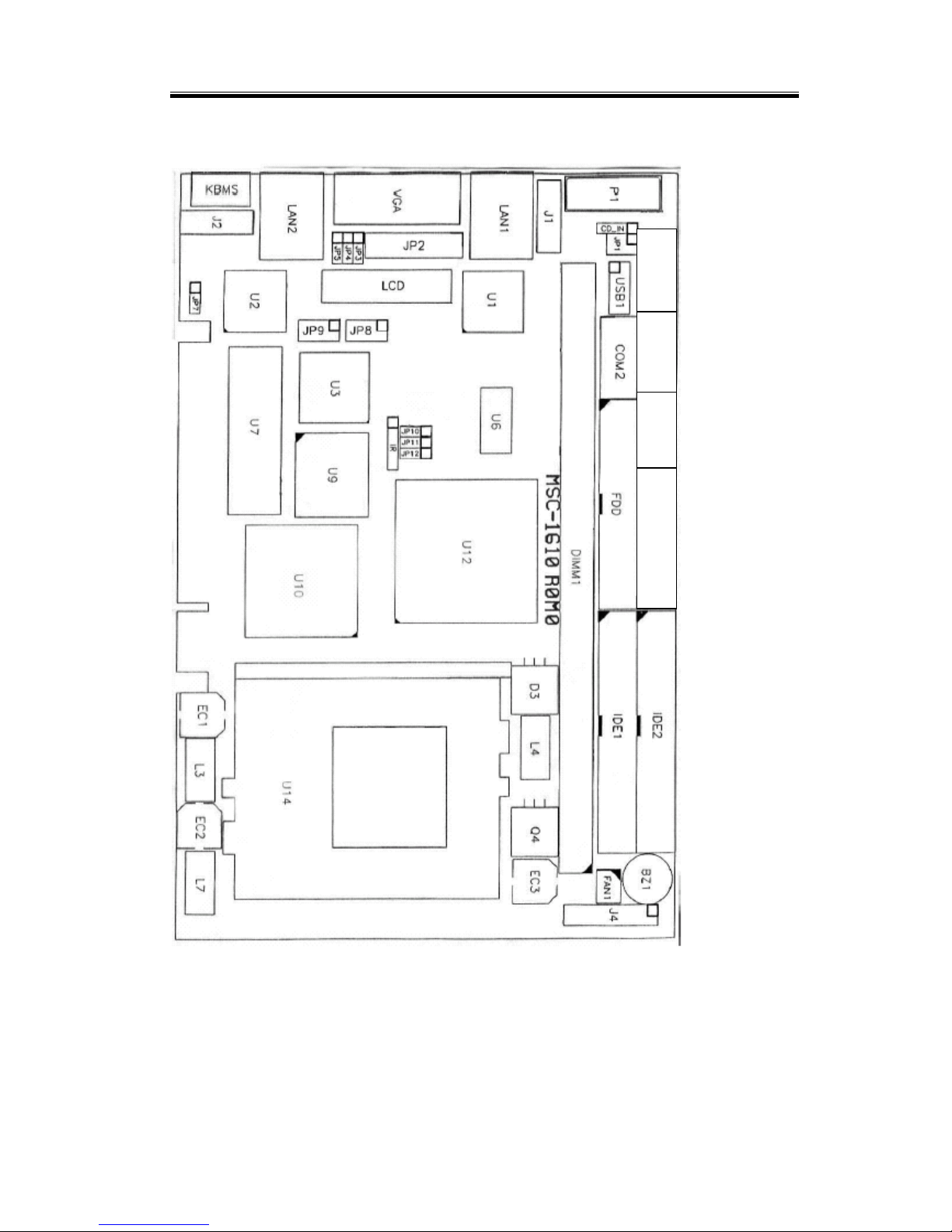
2.1 Components Location
This figure shows the locations of all sockets, jumpers,
connectors and major components on the MSC-1610. All
configuration of the MSC-1610 are in correct positions when it
is shipped from the factory. MSC-1610 will function as
required without modification. However, in order to allow
system tuning, some of the jumpers are designed to be user
configurable.
Page 19
Chapter 2: Hardware Configuration
7
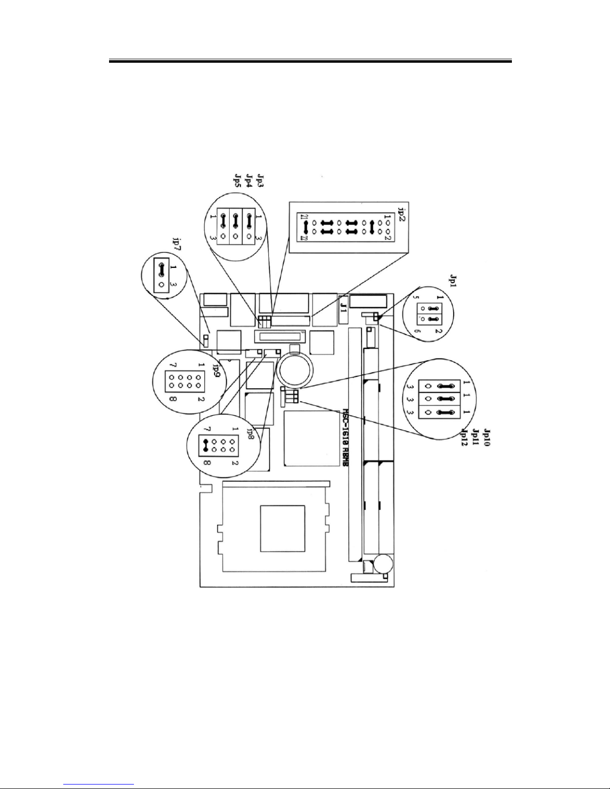
2.2 Jumpers
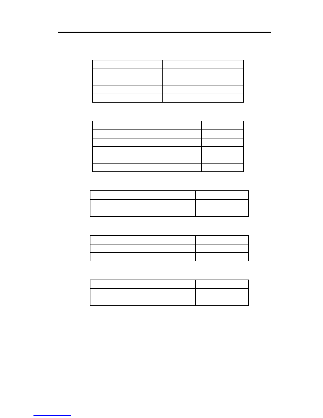
The location of the various jumpers on the MSC-1610 are as
shown below:
The succeeding sections provide details on how to properly
set these jumpers.
Page 20
MSC-1610 User’s Manual
8
2.2.1 CPU Base Speed Select (JP11, JP12)
CPU clock JP11 JP12
66.6MHZ 2-3 2-3
100MHz 1-2 2-3
Auto /133 MHz *1-2 *1-2
2.2.2 Power Source (JP1, J4, J1)
Power Source JP1 J4 J1
Use AT
Power Supply
3-5,
4-6
NC NC
Use ATX Power
Supply on
Backplane
*1-3,
*2-4
17-18 to
Power Switch
Cable to
Backplane
2.2.3COM2 Mode Select (JP2)
Mode JP2
RS232 *5-6,9-11,10-12,15-17,16-18,21-22
RS422 3-4,7-9,8-10,13-15,14-16,21-22
RS485 1-2,7-9,8-10,19-20
2.2.4 VGA Enable / Disable (JP10)
Enable / Disable JP10
On board VGA ENABLE *1-2
On board VGA DISABLE 2-3
2.2.5 LCD Voltage Selection (JP5)
Voltage Selector JP5
5V *1-2
3.3V 2-3
Page 21
Chapter 2: Hardware Configuration
9
2.2.6 Disk On Chip (M-System) Address Select (JP9)
I/O ADDRESS JP9
D0000-D1FF *1-2
D200-D3FF 3-4
D400-D5FF 5-6
D600-D7FF 7-8
2.2.7 Watch Dog Timer (JP8)
Watch Dog Timer JP8
1 Sec. 1-2
10 Sec. *3-4
30 Sec. 5-6
Enable 7-8(open)
Disable *7-8(close)
2.2.8 RTC CMOS Clear (JP10)
CMOS Selection JP10
Normal *1-2
Clear CMOS 2-3
2.2.9 ETHERNET Port 1 Enable / Disable (JP4)
Enable / Disable JP4
On board ETHERNET ENABLE *1-2
On board ETHERNET DISABLE 2-3
2.2.10 ETHERNET Port 2Enable / Disable (JP7)
Enable / Disable JP7
On board ETHERNET ENABLE *1-2
On board ETHERNET DISABLE 2-3
Page 22

MSC-1610 User’s Manual
10
2.3 Connectors
The connectors on the MSC-1610 are used to connect
external devices such as hard disk drives, floppy disk drives,
printers, keyboard, CRT, panel, serial ports, etc. Some
problems encountered with your system may be caused by
loose or improper connections. Ensure that all connectors are
in place and firmly attached.
Label Component
Audio Audio connector
USB2 USB connector
COM1 Serial port 1 connector
Parallel Parallel port connector
CN1 Parallel port
COM2 Serial port 2 connector
DIMM1 SDRAM Module Connector
FDD FDD connector
FAN1 CPU fan Connector
IR Infrared connector
IDE1,IDE2 HDD (IDE) connector
J1 Front panel connector
J2 Standby power connector
J4 CPU fan Connector
KBMS PS/2 keyboard /Mouse connector
LCD LCD connector
P1 External power connector
USB1 USB connector
VGA VGA CRT connector
Page 23
Chapter 2: Hardware Configuration
11
The locations of these connectors are shown below:
Audio USB2 COM1 Paralle1
Page 24

MSC-1610 User’s Manual
12
2.3.1 Standby Power Connector (J1)
Signals J2
NC 1
GND 2
NC 3
GND 4
PS-ON to backplane 5
5V(standby) 6
2.3.2 Front Panel Connector (J4)
Signals J1
Power LED, Pin 1+, Pin5-
1-5
External speaker Pin8+,Pin2- 2-8
System Management Interrupt 9-10
Suspend LED, Pin11+, Pin12- 11-12
System reset switch 13-14
HDD LED, Pin15+, Pin16- 15-16
ATX power button 17-18
2.3.3 External Keyboard Connector (J2)
Signals J6
Keyboard clock 1
Keyboard data 2
Mouse Clock 3
Ground 4
Power 5
Mouse data 6
2.3.4 USB Port 1 connector (USB1)
Signals USB0 USB1
VCC 1 10
USB - 3 8
USB + 5 6
GND 7 4
GND 9 NC
2.3.5 Infrared Connector (IR)
Page 25
Chapter 2: Hardware Configuration
13
Signals IR
VCC 1
NC 2
IRRX 3
GND 4
IRTX 5
2.3.6 External Power Connector (P1)
Signals P1
+12V 1
GND 2
GND 3
VCC 4
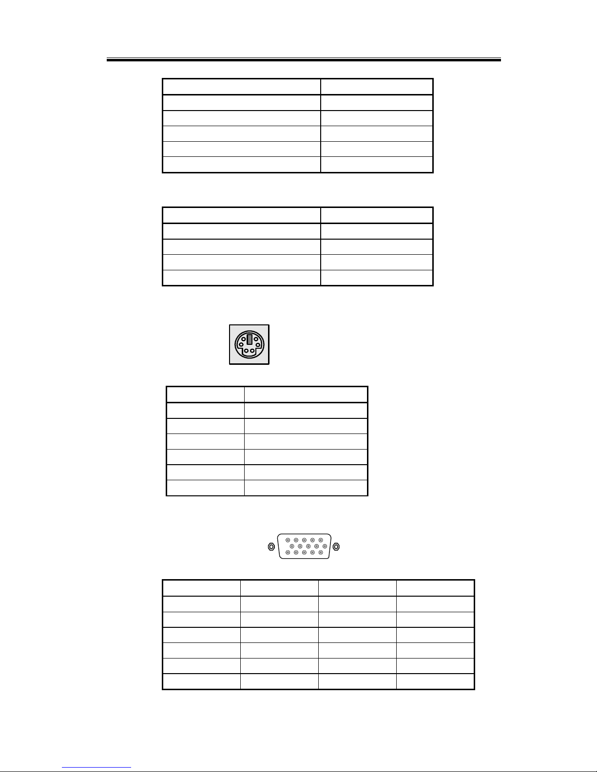
2.3.7 PS2 Keyboard / Mouse Connector (KBMS)
1
2
3
4
56
Pin no. Signal
1 KB data
2 MS data
3 GND
4 VCC
5 KB clock
6 MS clock
2.3.8 VGA CRT Connector (VGA)
6
15
10
15 11
Pin no. Signal Pin no. Signal
1 RED 9 N/C
2 GREEN 10 GND
3 BLUE 11 N/C
4 N/C 12 DCC data
5 GND 13 H-SYNC
6 GND 14 V-SYNC
Page 26
MSC-1610 User’s Manual
14
7 GND 15 DDC clock
8 GND
2.3.9 LCD Connector (LCD)
1
2
43
44
Pin no. Signal Pin no. Signal
1 +12V 2 +12V
3 5V/3.3V 4 5V/3.3V
5 FLM 6 ENAVEE
7 LP 8 ENAVDD
9 M 10 ENABKL
11 GND 12 GND
13 SHFCLK 14 GND
15 GND 16 GND
17 P0 18 P1
19 P2 20 P3
21 P4 22 P5
23 P6 24 P7
25 P8 26 P9
27 P10 28 P11
29 P12 30 P13
31 P14 32 P15
33 P16 34 P17
35 P18 36 P19
37 P20 38 P21
39 P22 40 P23
Page 27

Chapter 2: Hardware Configuration
15
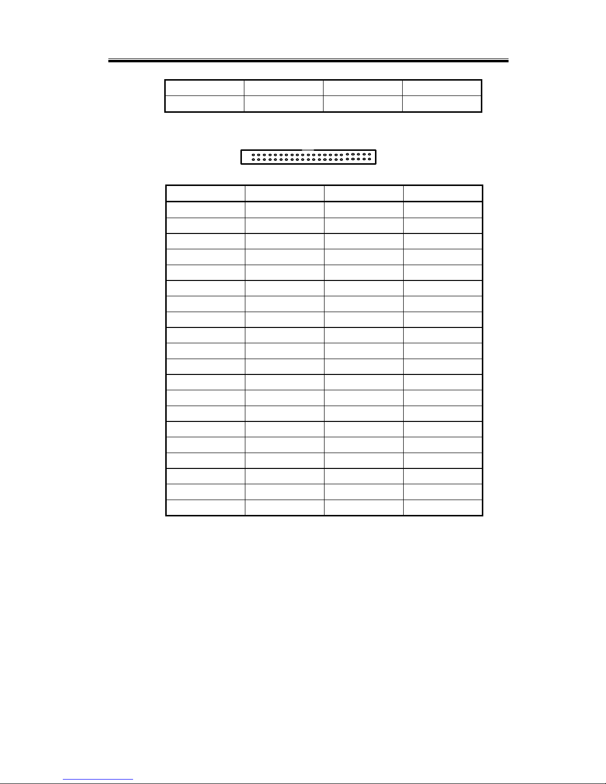
2.3.10 HDD (IDE) Connectors (IDE1, IDE2)
1
2
39
40
Pin no. Signal Pin no. Signal
1 - RST 2 GND
3 D7 4 D8
5 D6 6 D9
7 D5 8 D10
9 D4 10 D11
11 D3 12 D12
13 D2 14 D13
15 D1 16 D14
17 D0 18 D15
19 GND 20 N.C.
21 DMA REQ 22 GND
23 IOW 24 GND
25 IOR 26 GND
27 IORDY 28 GND
29 DMA ACK 30 GND
31 iINT REQ 32 N.C
33 A1 34 ATA Sel.
35 A0 36 A2
37 CS0 38 CS1
39 -ACT 40 GND
Page 28

MSC-1610 User’s Manual
16
2.3.11 FDD Connector (FDD)
1
2
33
34
Pin no. Signal
1,3,5,7,9,…..
33
GND
2 Density Select0
4, N.C
6 Density Select1
8 Index
10 Motor Enable 0
12 Driver Select 1
14 Driver Select 0
16 Motor Enable 1
18 Direction
20 Step Pulse
22 Write Data
24 Write Enable
26 Track 0
28 Write Protect
30 Read Data
32 Select Head
34 Disk Change
Page 29
Chapter 2: Hardware Configuration
17
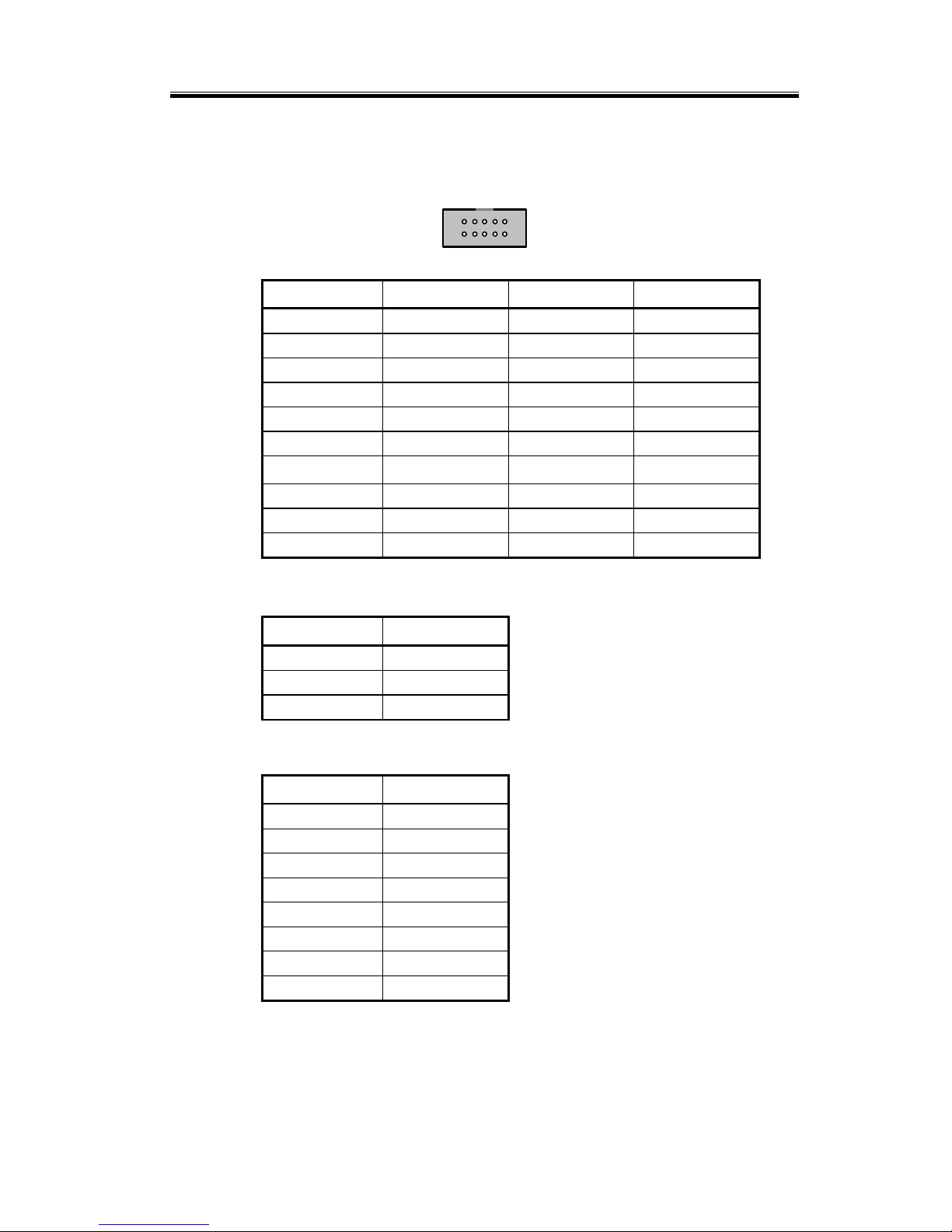
2.3.12 Serial Port 2 Connector (COM2) – RS232/422/485
Connector
1
2
9
10
Pin no. RS232 RS422 RS485
1 DCD TX- DATA2 DSR N.C N.C
3 RX TX+ DATA+
4 RTS N.C N.C
5 TX RX+ N.C.
6 CTS N.C N.C
7 DTR
RX-
N.C.
8 RI N.C N.C
9 GND GND GND
10 N.C. N.C. N.C.
2.3.13 CPU Fan Connector (FAN1)
Pin no. FAN1
1 GND
2 +12V
3 Speed Detect
2.3.14 LAN Port Connector (LAN1/LAN2)
Pin no. J4
1 TX+
2 TX3 RX+
4 N/C
5 N/C
6 RX7 N/C
8 N/C
Page 30
MSC-1610 User’s Manual
18
2.3.15 Parallel Port /COM1/USB2/Audio Connector (CN1)
Audio Connector
Pin no. Signal Pin no. Signal
1 MIC IN 2 N.C
3 LINE IN (L) 4 Audio GND
5 LINE IN (R) 6 Audio GND
7 LINE OUT (L) 8 Audio GND
9 LINE OUT (R) 10 MONO OUT
USB2 Connector
Pin no. Signal Pin no. Signal
1 USB VCC 2 USB GND
3 USB data 2- 4 USB GND
5 USB data 2+ 6 USB data 3+
7 USB GND 8 USB data 39 USB GND 10 USB VCC
COM1 Connector
Pin no. Signal Pin no. Signal
1 DCD1 2 DSR1
3 RXD1 4 RTS1
5 TXD1 6 CTS1
7 DTR1 8 RI1
9 COM GND 10 N.C.
Parallel Port Connector
Pin no. Signal Pin no. Signal
1 Strobe 2 Auto Form Feed
3 Data0 4 Error
5 Data1 6 Initialization
7 Data2 8 Select
9 Data3 10 GND
11 Data4 12 GND
13 Data5 14 GND
15 Data6 16 GND
17 Data7 18 GND
19 Acknowledge 20 GND
21 Busy 22 GND
23 Paper Empty 24 GND
25 Printer Select 26 GND
Page 31

19
C h a p t e r 3
System Installing
This chapter describes the procedures for installing the
MSC-1610 CPU card into your system and also, procedures for
installing device drivers.
The following is a list of typical peripherals required to build a
minimum system:
Power supply and passive backplane (optional)
IBM PC/AT keyboard
Display monitor
Floppy or hard disk with MS-DOS or Flash Disk
emulator
To build the system, you may need to install board components
(such as CPU, memory), configure the system (setting DIP
switches and jumpers for component compatibility or to enable
functions), connect the input/output devices, and set up the
operating system. For the location of the components and
connectors, please refer to the chapter 2 for details.
Page 32
MSC-1610 User’s Manual
20
3.1 Installing the DIMMs
The MSC-1610 single board computer accepts 32 MB up to
512MB of SDRAM. The single 168-pin SDRAM Dual
Inline Memory Module (DIMM) sockets will accept 64 and
72 bit DIMM modules (3.3V memory – unbuffered SDRAM
only).
The single board computer will accept only DIMM with
gold-plated contacts. To ensure reliable operation at zero
wait states, use only 10ns or faster SDRAM DIMM for bus
speeds less then 133MHz. For 133MHz or higher, use only
7.5ns or faster SDRAM DIMM.
Note: Before performing the following procedures, remove the
board from the backplane and lay it on a flat
ESD-protected, non-static surface.
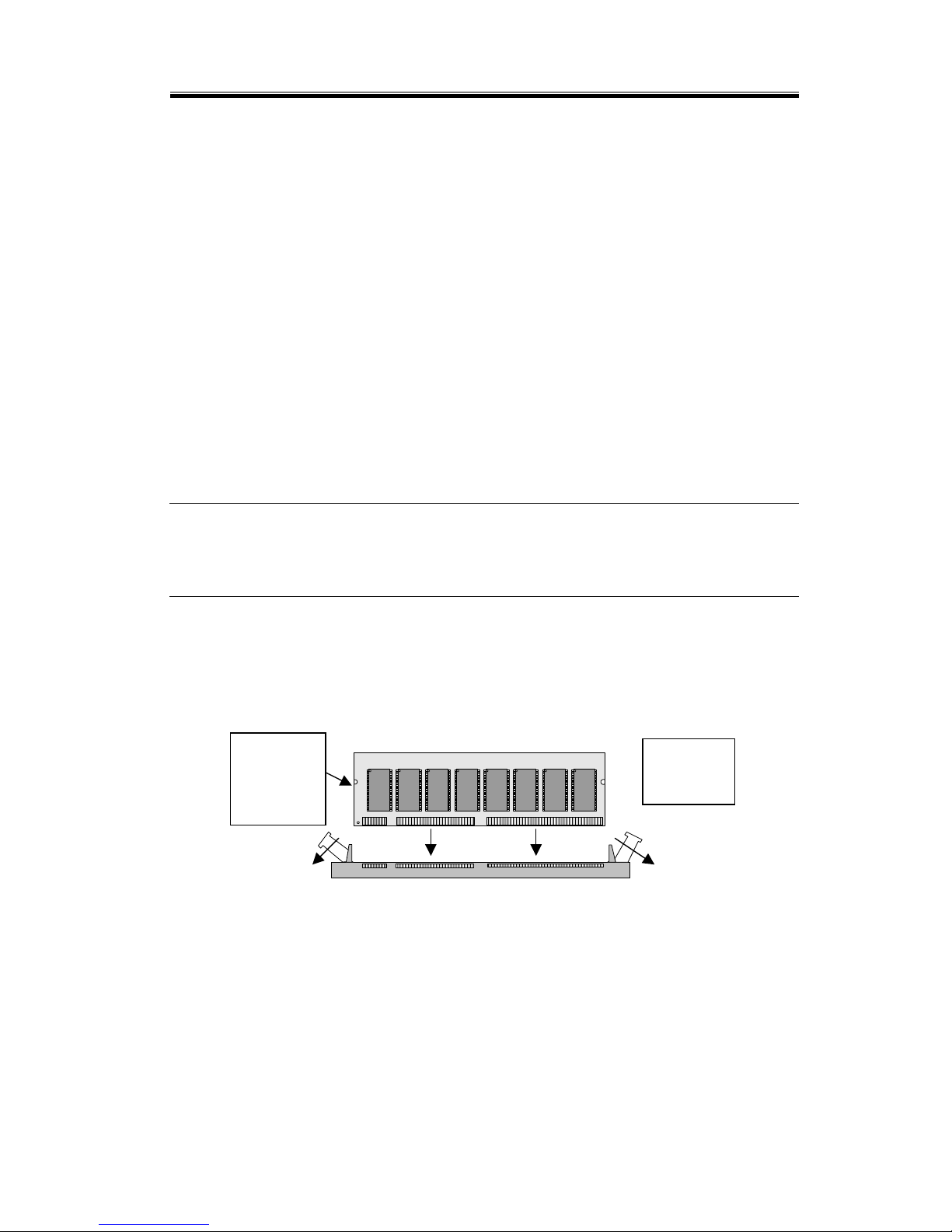
1. Move the module release levers (on each end of the socket)
outward, away from the socket.
LGS
GM71V65163CT5
LGS
GM71V65163CT5
LGS
GM71V65163CT5
LGS
GM71V65163CT5
LGS
GM71V65163CT5
LGS
GM71V65163CT5
LGS
GM71V65163CT5
LGS
GM71V65163CT5
2. Place the DIMM so that the two notches on the contact
edge line up with the two alignment nodes in the DIMM
socket. Insert the DIMM into the socket at a 90-degree
angle.
N
otched
ends of
memory
module
Module
release
Page 33
Chapter 3: Installing the Slot Board Computer
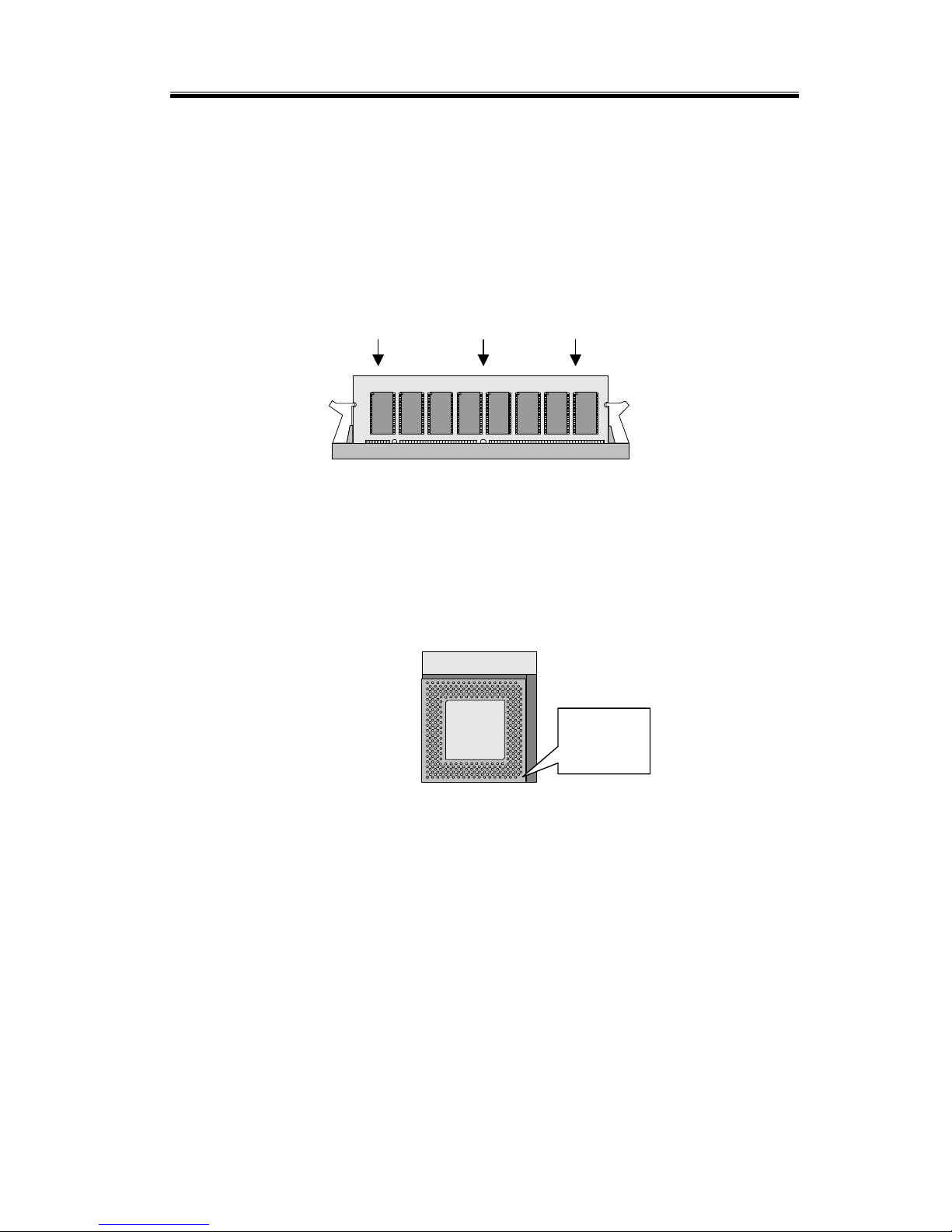
21
3. Using both hands, press downward and guide the DIMM
into the socket. The module release levers will return to
their upright position when the DIMM is completely
seated in the socket. The pegs on the tips of the release
levers should align with the notches on both ends of the
DIMM.
Apply even downward pressure when installing
LGS
GM71V65163CT5
LGS
GM71V65163CT5
LGS
GM71V65163CT5
LGS
GM71V65163CT5
LGS
GM71V65163CT5
LGS
GM71V65163CT5
LGS
GM71V65163CT5
LGS
GM71V65163CT5
3.2 Installing the CPU
1. Match key-pin on the CPU with key-pin of the PGA370
socket.
PGA 370
CPU
PGA 370
CPU
PGA370
2. To complete the installation, gently press the CPU onto
place. Double check the insertion and orientation of the
CPU before pressing. Improper installation will result in
permanent damage to the CPU.
3. Install the heat sink on top of the CPU properly.
CPU key
p
in
Page 34

MSC-1610 User’s Manual
22
3.3 Completing the Installation
To complete the installation, the following steps should be
followed:
1. Make sure the power is off.
2. Set the configuration jumpers in accordance with Chapter 2.
3. Install the MSC-1610 CPU card into one of the slots in a
passive backplane. Or, just take the MSC-1610 alone as a
single board computer.
4. Connect the required I/O cables and peripherals, i.e.
floppy disk, hard disk, monitor, keyboard, power supply
and etc.
Note: The color of pin one is usually red or blue, while others
are gray.
5. Check again and then turn on the power.
3.4 VIA Service Pack (VIA 4In 1)
3.4.1 VIA 4 in 1 Driver Installation Procedure:
1. Close all other programs and put driver disk into CD-ROM
in your computer.
2. Open VIA Chipset folder
CDROM:\Chipset\VIA4in1\
3. Double click the setup.exe file. This will automatically
open the installation wizard.
4. Bypass the “Welcome” dialog by clicking “Next’
5. This is the README file, which contains similar
information to this installation guide. Click “Yes” to
Page 35

Chapter 3: Installing the Slot Board Computer
23
continue.
You will now be presented with the option of either
a normal or quick install.A quick install will
automatically install all necessary files without
presenting you with any options.
A normal install can be used to choose to un-install
drivers or not install particular drivers.
Choose quick install unless you want to un-install
any particular drivers or want to chose particular
drivers. After the progress bar shows that the
installation is complete, choose the restart option.
OR Choose normal install if you want to
un-install any particular drivers or want to chose
particular drivers.
6. The 4in1 drivers will automatically detect what drivers you
neer and will tick or check the boxes corresponding to the
necessary drivers. It is recommend that you are an
advanced user or want to check un-install instead of install.
3.4.2 About VIA 4 IN 1 drivers:
VIA 4 In 1 driver includes four system drivers to improve
the performance and maintain the stability of systems using
VIA chipsets. These four drivers are: VIA Registry (INF)
Drivers,VIA AGP VxD driver, VIA ATAPI Vendor Support
Driver and VIA PCI IRQ Miniport Driver.
The 4in1 drivers automatically detect your operating
system and will install only what is necessary. For your
information:
VIA IDE Bus Master Driver: For Windows NT users, the
VIA IDE Bus Mastering driver is the only driver to be
installed in your system.
VIA Registry (INF) Driver will be installed. The driver will
Page 36

MSC-1610 User’s Manual
24
enable the VIA Power Management function.
VIA AGP Vxd Driver will provide service routines to your
VGA driver and interface directly to hardware, providing
fast graphical access.
The IDE Filter driver enables the performance enhancing
bus mastering functions on ATA-capable Hard Disk Drives
and ensures IDE device compatibility. (Also known as the
ATAPI Vendor Support Driver)
VIA PCI IRQ Miniport Driver will be installed under
Windows 98 only. It sets the systm’s PCI IRQ routing
sequence.
OS driver IDE Filter
Driver
AGP
Driver
Via INF
Driver
IRQ
Driver
IDE
mini-point
Windows 98
Y Y Y Y
Windows ME
Y Y Y
Windows2K
Y Y Y
Windows NT
Y
Windows XP
Y Y Y
3.5 Installing AUDIO Driver
The audio folder and Type D:>\AUDIO\SETUP.EXE
(where D equals the location of the setup file) in the run
command prompt or double click the setup.exe file. Select
“Install”.
After the system reboots, the driver will be installed
completely.
Page 37

Chapter 3: Installing the Slot Board Computer
25
3.6 Installing VGA Driver
The onboard VGA interface of the MSC-1610 supports
traditional analog CRT monitors and a wide range of
popular LCD, EL, and gas plasma flat panel displays. It can
drive CRT displays with resolutions up to 1024x768 in
16.7M colors. It is also capable of driving color panel
displays with resolutions of 800x600 in 16.7M colors.
3.6.1 VGA Driver for Windows 95/98
Click Start, then Settings, then Control Panel. Start the
"Display" applet program. Select the "Settings" page, push
the "Change Display Type" button. Push the "Change"
button in the "Adapter Type" area.
Push the "Have Disk" button and press "OK".
Specify the path to the new driver and press the
<ENTER> key:
Example 1: Insert the drivers disk in the CD-ROM drive,
and enter D:\VGA\WIN_98
Example 2: Type in the name of the directory where you
copied the drivers, either on your local hard
drive or on a network share.
Example 3: If you're not sure exactly where the drivers
are, choose the "Browse..." button are find
them.
The "Select Device" dialog box will appear. Select the
adapter that corresponds to the one you installed in your
machine and click OK.
Windows 95/98 will copy the display drivers to the
proper directories on your system. Continue choosing Close
until asked to restart your machine from the "Systems
Page 38

MSC-1610 User’s Manual
26
Settings Change" dialog box.
After the system has restarted, you can go back into the
Display applet and select alternate screen resolutions and color
depths.
3.6.2 VGA Driver for Windows NT 4.0
Step 1: Click the Start button, then go to Settings and click
on Control Panel.
Click on the Display icon to start the Display
Properties window.
Click on the Settings tab, and then click on Display
Type.
In the Change Display Type window, click on
Change in Adapter Type.
This will bring up the Select Device Window.
Step 2: Chips & Technologies display drivers can be installed
from a manufacturer supplied Installation Diskette, or
from the default drivers provided on the Windows
NT 4.0 CDROM.
Installing from Manufacturer supplied diskette
----------------------------------------------
In the Change Display window, click on Have Disk. Follow
the directions on the screen to supply the directory where the
Windows NT driver files are located. Then select OK, or
press enter. Select Chips Video Accelerator from Display list
provided, then click OK or press enter.
You will then see a warning panel about Third Party
Drivers. Click on Yes to finish the install.
Once the installation is complete, the system must be
shut down and restarted for the new drivers to take effect.
Page 39

Chapter 3: Installing the Slot Board Computer
27
Installing Drivers provided on NT 4.0 CDROM
----------------------------------------------
In the Change Display window, from the list of
Manufacturers, select Chips & Technologies. In the Display
Window, select Chips & TechnologiesVideo Accelerator,
then click OK or press enter.
You will then see a warning panel about Third Party
Drivers. Click on
Yes to finish the install.
Follow the directions on the screen to supply the
directory where the Windows NT driver files are located.
Then select OK, or press enter.
Once the installation is complete, the system must be
shut down and restarted for the new drivers to take effect.
Step 3: When the system has restarted, the default graphics
mode ( usually 640x480x256color ) has been
automatically selected.
Click the Start button, then go to Settings and click on
Control Panel. Click on the Display icon to start the Display
Properties window.
Click on the Settings tab.
A new screen setting can be selected using either of the
following methods:
1: Use the slide-bar in the Desktop Area to select new setting.
2: Click on List All Modes. From the list provided, select a
new setting, then click OK or press enter.
Click on Test to test the newly selected graphics mode.
Page 40

MSC-1610 User’s Manual
28
Follow the instructions given on the screen. A test screen
should appear, followed by the Testing Mode window.
Click on Yes to continue. Click on Apply to switch to the
new graphics mode.
Graphics modes are changed dynamically on NT 4.0, so
you do not meed to shutdown and restart for the new
screen settings to work.
Page 41

Chapter 3: Installing the Slot Board Computer
29
3.6.3 VGA Driver for Windows 2000
Click the "Start" button, then select the "Settings" tab and
click on "Control Panel".
Click on the "System" icon to start the System Properties
window.
Click on the "Hardware" tab, and then click on "Device
Manager" button.
Double click the "Video Controller" , then the "Properties"
button found there.
Select the "Driver" tab, then the "Update Driver..." button.
Select the radio button that begins "Search for a suitable
driver for my device…." and press the "Next" button.
Select “Specify a location” Click the "Next" button and
select the location of the driver files.
Example D:\vga\win2k_xp
Make a selection from the list provided, and click "Next".
Your system for the changes to take effect.
When the system has changed, the default graphics mode
(usually 640x480x256color ) has been automatically
selected.
Page 42

MSC-1610 User’s Manual
30
To change the display resolution and/or colors...
------------------------------------------------Click the Start button, then go to Settings and click on
Control Panel. Click on the Display icon to start the Display
Properties window. Click on the Settings tab.
A new screen setting can be selected using either of the
following methods:
1: Use the slide-bar in the Desktop Area to select new
setting.
2: Click on List All Modes. From the list provided,
select a new setting, then click OK or press enter.
3. Click the Apply button to make changes.
3.6.4 VGA Driver for Windows XP
Click the "Start" button, then select the "Control Panel"
and click on it.
Click on the "System" icon to start the Display Properties
window.
Click on the "System" icon to start the System Properties
window.
Click on the "Hardware" tab, and then click on "Device
Manager" button.
Double click the "Video Controller" , then the "Properties"
button found there.
Select the "Driver" tab, then the "Update Driver..." button.
Click the "Don't search..." radio button and click "Next.
Click "Have Disk" and then "Browse" to the location of
the driver files.
Select the “chips2k.inf file”. Click "Open". Click "OK".
Click "Next". If Logo Testing Dialog comes up, click
"Continue Anyway".
You may need to shutdown and reboot the system for the
changes to take effect. Follow the prompts.
Page 43

Chapter 3: Installing the Slot Board Computer
31
When the system has restarted, the default graphics mode
(usually 640x480x256color) has been automatically
selected.
To change the display resolution and/or colors...
-------------------------------------------------
Click the Start button, then go to Settings and click on
Control Panel.
Click on the Display icon to start the Display Properties
window.
Click on the Settings tab.
A new screen setting can be selected using either of the
following methods:
1: Use the slide-bar in the Desktop Area to select new setting.
2: Click on List All Modes. From the list provided, select a
new setting, then click OK or press enter.
Click the Apply button to make changes.
3.7 Configuring Ethernet Interface
Onboard Ethernet interface of the MSC-1610 CPU card
supports all major network operating systems. Please
follow the steps below to configure the network.
3.7.1 Connect the Network Cable
1. Connect a Twisted Pair Ethernet (TPE) network cable to
RJ-45 :
For 100 BASE-TX, your network cable must be Category
5, twisted pair wiring. If you plan to run at 100Mbps, it
must be connected to a 100BASE-TX hub or switch (not a
100 BASE-T4 hub).
For 10BASE-T, use Category 3, 4, or 5 twisted pair wiring.
If you want to use a residential environment, you must use
a Category 5 cable.
Page 44

MSC-1610 User’s Manual
32
2. To configure networking, continue with the procedures
specific to your operating system outlined in the latter part
of this chapter.
3.7.2 Making a Setup Floppy Disk
If you need to use a floppy disk to install the networking
drivers, use MAKEMS.BAT (for Microsoft operating
systems) or MAKENW.BAT (for Netware), located in the
\MAKEDISK directory on the CD. The format for the
command is:
D:\LAN\MAKEDISK\MAKEMS.BAT D: A:
In the example above, D: is your CD-ROM drive and A: is
your floppy drive.
3.7.3 Configuring the Network and Installing the Drivers
Novell NetWare 5.0 Only
Use the NetWare* Install program to install driver in
Novell NetWare 5.0. For Novell NetWare 4.1x, see the
section Novell NetWare 4.X Only. For Novell Netware 3.11
and 3.12, see the readme files. For DOS ODI, see the
section DOS and Windows 3.1 Setup for Novell NetWare
DOS ODI Clients. The following procedure is a condensed
description of the installation process.
1. From the NetWare console, type LOAD NWCONFIG and
press Enter.
2. From the Configuration Options screen, choose
“Driver options” and press Enter.
3. Choose “Configure network drivers” and press Enter.
If drivers were previously loaded, a list of these drivers
appears.
4. Choose “Select an additional driver” and press Enter. A
list of drivers appears.
Page 45

Chapter 3: Installing the Slot Board Computer
33
5. Insert the floppy disk or CD and press the Insert key to
install an unlisted driver.
6. Specify the correct path to your media if necessary by
pressing F3. Press Enter to search the floppy or
CD-ROM driver.
7. Highlight the Intel PRO PCI Adapter and press Enter to
select it.
8. The succeeding screens ask for frame and protocol
types. Use the arrow keys to select specific items or
choose the defaults. Select “Save parameters and load
driver” to continue.
9. To complete the driver installation process, go back to
the Installation Options screen by pressing the Esc key
until you see it.
10. Choose Exit to return to the console prompt.
Note: If the network cannot transmit or receive data after the
installation, you may need to modify the frame type in the
AUTOEXEC.NCF file.
Novell NetWare 4.1x Only
Use the NetWare install program to install driver in Novell
NetWare 4.1x. For Novell NetWare 3.11 and 3.12, see the
README files. For DOS ODI, see the section DOS and
Windows 3.1 Setup for Novell NetWare DOS ODI Clients.
The following procedure is a condensed description of
installation process.
Note: Before installing, either load DOS or NetWare drivers for your
computer’s CD-ROM drive or create a floppy disk from the
CD on a different computer.
1. From the NetWare console, type LOAD INSTALL and
press Enter.
2. From the Install Options screen, choose “Driver options”
and press Enter.
Page 46

MSC-1610 User’s Manual
34
3. Choose “Configure network drivers” and press Enter. If
drivers were already loaded, a list of these drivers appears.
4. Choose “Select an additional driver” and press Enter. A list
of drivers appears.
5. Insert the floppy disk or CD and choose “Install an unlisted
driver” by clicking “Insert”.
6. Specify the correct path to your media if necessary by
pressing F3. Press Enter to search the floppy or CD-ROM
driver.
7. The driver name is displayed: Intel PRO/100+ Adapter.
Press Enter to select it.
8. The succeeding screens ask for frame and protocol types.
Use the arrow keys to select specific items or choose the
defaults. Select “Save parameters and load driver” to
continue.
9. To complete the driver installation process, go back to the
Installation Options screen by pressing the Esc key until
you see it.
10. Choose Exit to return to the console prompt.
Note: If the network cannot transmit or receive data after the
installation you may need to modify the frame type in the
AUTOEXEC.NCF file.
Windows 95 / 98
Windows 95 / 98 Automatic Configuration
PCI computers automatically detect and configure
PCI-compliant adapters while booting. The BIOS
automatically sets the adapter IRQ level and I/O address
each time you start your computer.
Page 47

Chapter 3: Installing the Slot Board Computer
35
Start your computer to automatically configure the adapter.
Resource configuration is complete when Windows 95 / 98
starts.
If your computer displays an error while booting, it may
require additional step to configure. See the section PCI
Installation Tips in the latter part of this chapter for more
details.
Install Network Drivers from Disk
Have your Windows 95 / 98 installation CD or diskettes
available, since you’ll be prompted for them when you
install the new adapter.
1. After connecting the cable, start Windows 95/98. You will
see the New Hardware Found dialog box. If this box does
not appear and Windows starts normally, you may need to
manually add the adapter. See the MS.TXT readme file in
the \MS directory for more information.
2. Click “Driver from disk provided by hardware
manufacturer”, and then click “OK”. You’ll see the Install
From Disk dialog box.
3. Insert the Driver adapter disk.
4. Specify D:\ (or the appropriate drive letter for the
CD-ROM drive) or A:\ (for floppy) as the path, then click
OK.
5. Follow instructions from the Windows installation disks
and restart when prompted.
Windows NT Automatic Configuration
PCI computers automatically detect and configure
PCI-compliant adapters while booting. The BIOS
automatically sets the adapter IRQ level and I/O address
each time you start your computer.
Start your computer to automatically configure the adapter.
Page 48

MSC-1610 User’s Manual
36
Resource configuration is complete when Windows 95/98
starts.
If your computer displays an error while booting, it may
require additional step to configure. See the section PCI
Installation Tips in the latter part of this chapter for more
details.
Windows NT Version 4.0 Only
After connecting the cables and starting Windows NT, you
need to install the correct drivers.
1. Double-click the Network icon in the Control Panel.
2. Click the Adapters tab.
3. Click “ADD”. You’ll see a list of adapters.
4. Don’t select an adapter from list. Instead, insert the Driver
Disk or CD into the appropriate drive and click Have Disk.
5. Specify the appropriate drive in the dialog box and click
OK. Then follow the prompts to complete the installation.
When the adapter is added you’ll see a new adapter listed
in the Network adapters list.
6. Click Close to finish.
7. Restart Windows NT when prompted.
Windows NT Version 3.51 Only
After connecting the cables and starting Windows NT, you
need to install the correct drivers.
1. Double-click the Network icon in the Control Panel.
2. Click ADD Adapter.
3. When the list of adapters appears, scroll to the end of the
list and select <Other> requires disk from manufacturer and
then click Continue.
Page 49

Chapter 3: Installing the Slot Board Computer
37
4. Insert the Driver Disk or CD into the appropriate drive,
specify that drive, and click OK.
5. Select the INTEL PRO Adapter and click OK. Drivers and
utilities are installed.
6. The TCP/IP Configuration dialog box appears. Enter the
appropriate information and click OK. Remove the
installation disk or CD.
7. When prompted, restart Windows NT.
DOS and Windows 3.1 Setup for Novell NetWare DOS ODI
Clients
NOTE: Windows 95/98 users should refer to the previous
sections on Windows 95/98. NetWare Client 32 users
should refer to the NetWare readme files in the
\NETWARE directory.
DOS and Windows 3.1 Automatic Configuration
PCI computers automatically detect and configure
PCI-compliant adapters while booting. The BIOS sets the
adapter IRQ level and I/O memory address automatically
each time you start your computer.
Start your computer to automatically configure the adapter.
Resource configuration is complete when the DOS prompt
appears. You can now continue with the procedure below.
If your computer displays an error while booting, it may
require additional steps to configure a PCI adapter. See PCI
Installation Tips in the latter part of this chapter for more
information.
Run setup to Install Network Drivers
Setup can automatically install NetWare DOS ODI client
Page 50

MSC-1610 User’s Manual
38
drivers for you or display a readme file with installation
instructions for other NOS drivers.
1. If your computer already has network drivers installed,
restart the computer without loading them. If the drivers are
loaded from the AUTOEXEC.BAT or CONFIG.SYS file,
type REM in front of each line that loads a network driver.
Or, with DOS 6.x or later press F5 as DOS starts, to bypass
the drivers.
2. Insert the PRO/100+ adapter disk in a drive, switch to that
drive and at the DOS prompt, type SETUP and press Enter.
3.Select the adapter from the menu.
4. Select Automatic Setup from the Main menu. Then follow
the instructions on the screen. Setup displays the adapter’s
configuration and then runs a series of diagnostic tests that
make sure the adapter and network are functioning properly.
If Setup finds a problem, it displays the results and some
possible solutions.
5. When Setup finishes the tests, you’ll see the Install
Network Drivers screen.
6. Select the driver you want to install. Setup can install a
NetWare client driver for you. If you want to install other
drivers, Setup displays a readme file with installation
instructions.
PCI Installation Tips
PCI computers are designed to automatically configure
add-in cards each time the computer starts. Your PCI
computer sets the I/O address and IRQ level for your
network adapter when the computer starts. These values
cannot be changed by Intel adapter software. If you
experience a problem when the computer starts, you may
need to follow additional configuration steps.
Manual configuration is possible through the BIOS
Page 51

Chapter 3: Installing the Slot Board Computer
39
setup utility.
Some common PCI solutions are listed here:
Bus-master-enabled slots.
Reserve interrupts (IRQs) and/or memory addresses
for ISA adapters. This prevents PCI cards from
trying to use the same settings ISA cards are using.
Enable the PCI slot. Update your PCI BIOS. An
updated PCI system BIOS can correct some PCI
configuration problems. Call your computer
manufacturer to see if an updated BIOS version is
available for your computer.
Configure the slot for level-triggered interrupts. The
slot the adapter is using must be configured for
level-triggered interrupts rather than edge-triggered
interrupts.
3.8 Installing DiskOnChip of M-systems
3.8.1 Installing the Disk-On-Chip 2000 :
When installing or removing the DiskOnChip be sure to
first touch a grounded surface to discharge any static
electricity from your body.
Use the following procedure to install the DiskOnChip:
1. Align pin 1 of the DiskOnChip with the pin1 of socket.
2. Push the DiskOnChip into the socket carefully until it is
fully seated.
3. Check to make sure the DiskOnChip is installed securely,
and there are no bent pins.
Page 52

MSC-1610 User’s Manual
40
Caution: The DiskOnChip may be permanently damaged if
installed incorrectly.
4. To install the DiskOnChip as drive C on a system without a
hard disk, set the CMOS setup of drive C to NOT
INSTALLED (indicating that no physical magnetic disk is
installed), and reboot the computer. The DiskOnChip 2000
will install as drive C. The DiskOnChip needs to be
formatted with the system files in order to be a bootable
drive.
3.8.2 Configuring the DiskOnChip 2000 as the boot device:
In order to configure the DiskOnChip as the boot device,
the operating system files need to be copied into it.
Copying the operating system files into DiskOnChip should
be done lik+e in any other hard disk. The following is an
example of a typical initialization process:
1. Set the DiskOnChip as a regular drive in your system (not a
boot drive).
2. Install a bootable floppy diskette in drive A, and boot the
system from drive A.
3. At the DOS prompt, type SYS C: to transfer the DOS
system files to the DiskOnChip. (assuming theDiskOnChip
is installed as drive C)
4. Copy any files needed into DiskOnChip.
5. Remove floppy diskette and reboot the system. The system
will boot from the DiskOnChip and will allow you to run
and access any files that have been copied into the
DiskOnChip.
3.8.3 Configuring the DiskOnChip 2000 as the first drive:
The DiskOnChip can be configured as the last drive (default)
or as the first drive in the system. When configured as the
last drive, the DiskOnChip is installed as drive D if there is
Page 53

Chapter 3: Installing the Slot Board Computer
41
another hard drive installed, and as drive C if no other hard
drive is installed. When configured as the first drive, the
DiskOnChip is always installed as drive C. To configure the
DiskOnChip as first drive, proceed as follows:
1. Boot the system and make sure the DiskOnChip is installed
correctly as drive D.
2. At the DOS prompt type DUPDATE D: /FIRST /
S:DOC2000.EXB
3. After rebooting the system, the DiskOnChip will appear as
drive C:
Page 54

42
C h a p t e r 4
BIOS Configuration
Award's BIOS ROM has a built-in Setup program that allows
users to modify the basic system configuration. This type of
information is stored in battery-backup RAM (CMOS RAM).
When the power is off, it will retain the Setup information.
4.1 Entering Setup
Power on the computer and press <Del> immediately to allow
you to enter Setup. The other way to enter Setup is to power
on the computer, when the message below appears briefly at
the bottom of the screen during POST (Power On Self Test),
press <Del> key or simultaneously press <Ctrl>, <Alt>, and
<Esc> Keys.
TO ENTER SETUP BEFORE BOOT PRESS <CTRL-ALT-ESC>
OR <DEL> KEY
As long as this message is present on the screen you may
press the <Del> key (the one that shares the decimal point at
bottom of the numeric keypad) to access the Setup program.
In a moment, the main menu of the Award SETUP program
will appear on the screen.
You may use the cursor up/down keys to highlight the
individual menu items. As you highlight each item, a brief
description of that item’s function appears in the lower
windows. If you have a color monitor you can use the <Shift>,
<F2> keys to scroll through the various color combinations
available.
Page 55
Chapter 4: BIOS Configuration
43
4.2 The Main Menu
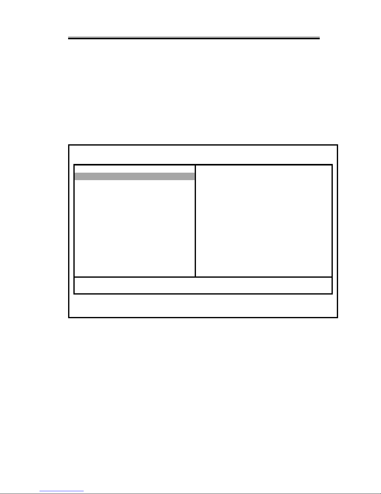
Once you enter Award’s BIOS CMOS Setup Utility, the
Main Menu will appear on the screen. The Main Menu
allows you to select from ten setup functions and two exit
choices. Use arrow keys to select among the items and press
<Enter> to accept or enter the sub-menu.
Phoenix – Award BIOS CMOS Setup Utility
Standard CMOS Features Frequency/Voltage Control
Advanced BIOS Features Load Fall-Safe Defaults
Advanced Chipset F Features Load Optimized Defaults
Integrated Peripherals Set Supervisor Password
Power Management Setup Set User Password
PnP/PCI Configuration Save & Exit Setup
PC Health Status Exit Without Saving
Esc : Quit ↑ ↓ ← → : Select Item
F10 : Save & Exit Setup
Time, Date, Hard Disk Type………
Page 56

MSC-1610 User’s Manual
44
4.3 Standard CMOS Setup
Phoenix – Award BIOS CMOS Setup Utility
Standard CMOS Features
Date (mm:dd:yy)
Time (hh:mm:ss)
Item Help
Menu Level
IDE Primary Master [ None ]
IDE Primary Slave [ None ] Change the day. Month.
IDE Secondary Master [RICOH CD-R/RW MP721] year and century
IDE Secondary Slave [ None ]
Drive A [1.44M. 3.5 in. ]
Drive B . [ None ]
Floppy 3 Mode Support [ Disable ]
Video [EGA/VGA]
Halt On [All . But Keyboard ]
Base Memory 640K
Extended Memory 251120K
Total Memory 252144K
↑↓→←: Move Enter : Select +/-PU/PD:Value F10:Save Esc:Exit F1:General Help
F5:Previous Values F6:Fail-Safe Defaults F7:Optiomized Defaults
Thu , Feb 7 2002
23 : 1 : 16
Page 57
Chapter 4: BIOS Configuration
45
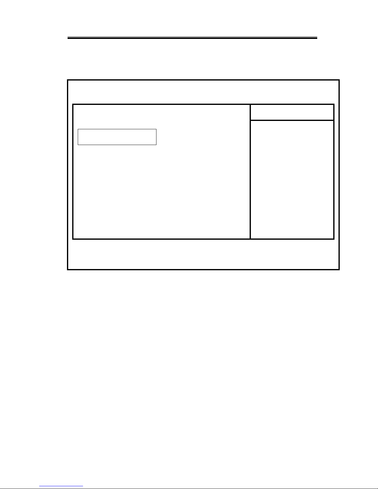
4.4 IDE Primary Master
Phoenix – Award BIOS CMOS Setup Utility
IDE Primary Master
IDE HDD Auto-Detection [ Press Enter]
Item Help
Menu Level
[ Auto ]
Access Mode [ Auto ] To auto-detect the
HDD’s size,head…….on
Capacity 0 MB This channel
Cylinder 0
Head 0
Precomp 0
Landing Zone 0
Sector 0
↑↓→←: Move Enter : Select +/-PU/PD:Value F10:Save Esc:Exit F1:General Help
F5:Previous Values F6:Fail-Safe Defaults F7:Optiomized Defaults
IDE Primary Master
Page 58
MSC-1610 User’s Manual
46
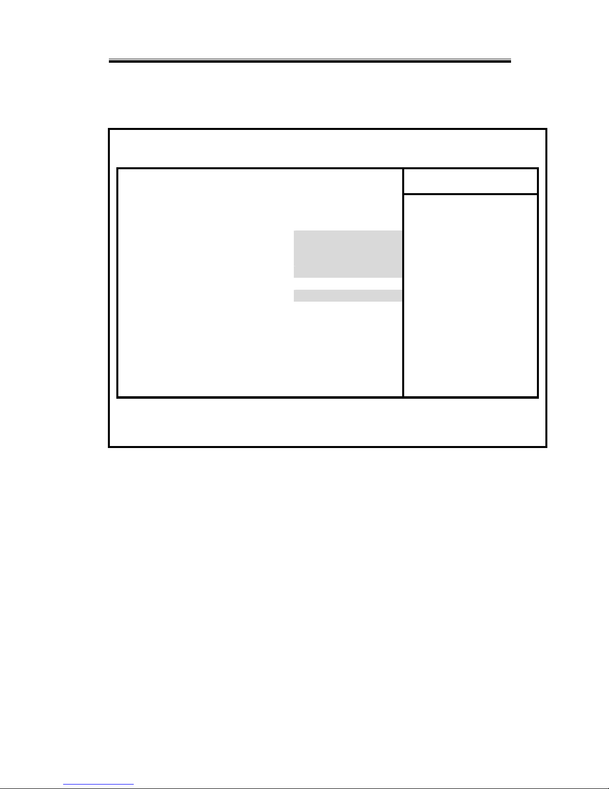
4.5 Advanced BIOS Features
Phoenix – Award BIOS CMOS Setup Utility
Advanced BIOS Features
Virus Warning [ Disabled ]
CPU Internal Cache [ Enabled ]
Item Help
External Cache [ Enabled ] Menu Level
CPU L2 Cache ECC Checking [ Enabled ]
Quick Power On Self Test [ Enabled ] Allows you to choose
First Boot Device [ SCSI ] The VIRUS warning
Second Boot Device [ Floppy ] Feature for IDE Hard
Third Boot Device [ CDROM] Disk boot sector
Boot Other Device [ Disabled ] Protection. If this
Swap Floppy Device [ Disabled ] Function is enabled
Boot Up Floppy Seek [ Enabled ] And someone attempt to
Boot Up Numlock Status [ On ] write data into this
Gate A20 Option [ Fast ] area , BIOS will show
Typematic Rate Setting [ Disabled ] a warning message on
* Typematic Rate (Chars/Sec) 6 Screen and alarm beep
* Typematic Delay (Msec) 250
Security Option [ Setup ]
OS Select For DRAM > 64MB [ Non-OS2 ]
Video BIOS Shadow [ Enabled ]
↑↓→←: Move Enter : Select +/-PU/PD:Value F10:Save Esc:Exit F1:General Help
F5:Previous Values F6:Fail-Safe Defaults F7:Optiomized Defaults
Page 59
Chapter 4: BIOS Configuration
47
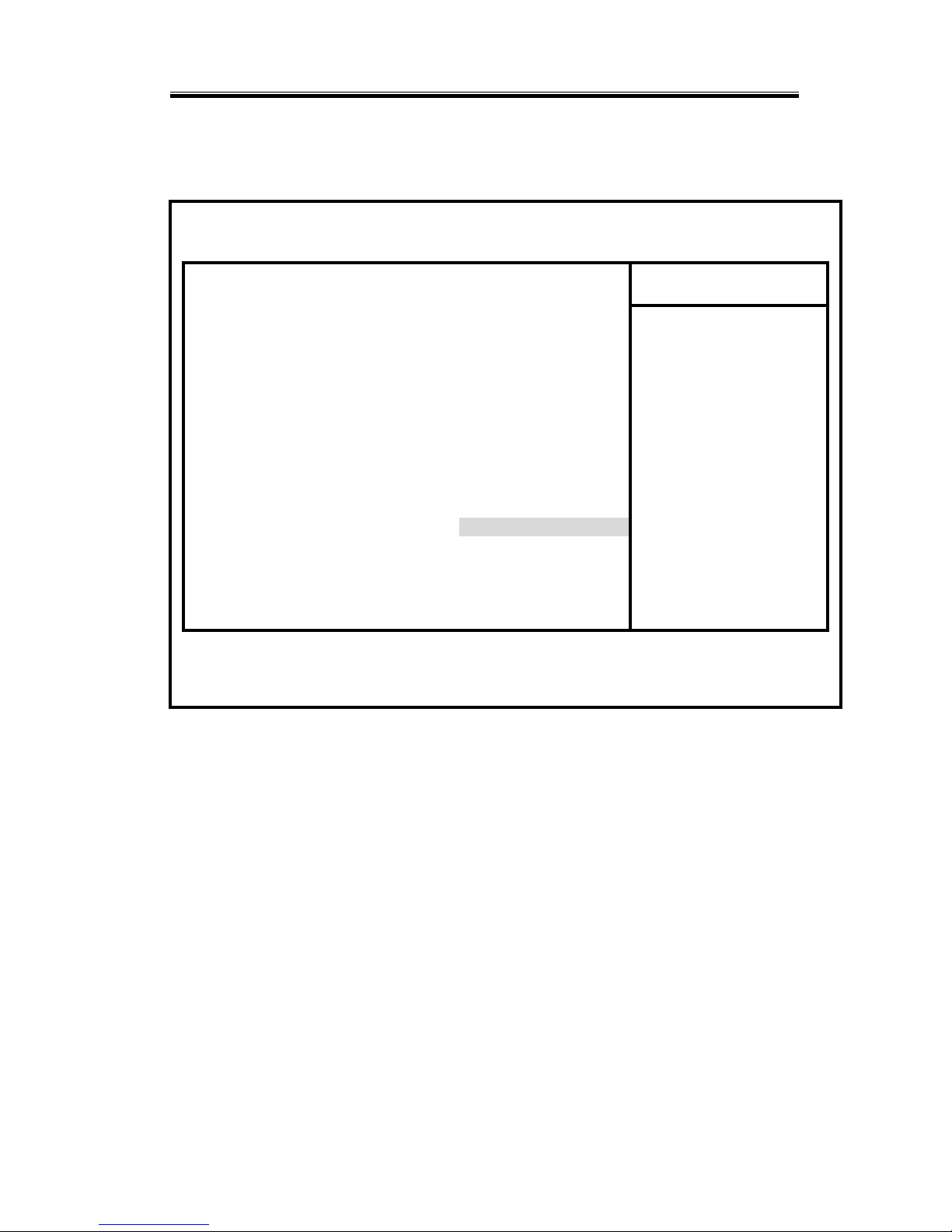
4.6 Advanced Chipset Features
Phoenix – Award BIOS CMOS Setup Utility
Advanced Chipset Features
DRAM Timing By SPD [ Disabled ]
﹡DRAM Clock
HOST Clock
Item Help
﹡SDRAM Cycle Length
3 Menu Level
﹡Bank Interleave
Disabled
Memory Hole [ Disabled ]
P2C/C2P Concurrency [ Enabled ]
System BIOS Cacheable [ Disabled ]
Video RAM Cacheable [ Disabled ]
AGP Aperture Size [ 64M ]
AGP Driving Control [ Auto ]
﹡AGP Driving Value
DA
AGP Fast Write [ Disabled ]
OnChip USB [ Enabled ]
USB Keyboard Support [ Enabled ]
USB Mouse Support [ Disabled ]
OnChip Sound [ Auto ]
CPU to PCI Write Buffer [ Enabled ]
PCI Dynamic Bursting [ Enabled ]
PCI Master 8 WS Write [ Enabled ]
↑↓→←: Move Enter : Select +/-PU/PD:Value F10:Save Esc:Exit F1:General Help
F5:Previous Values F6:Fail-Safe Defaults F7:Optiomized Defaults
Page 60
MSC-1610 User’s Manual
48
4.7 Integrated Peripherals
Phoenix – Award BIOS CMOS Setup Utility
Integrated Peripherals
OnChip IDE channe 10 [ Enabled ]
OnChip IDE channe 11 [ Enabled ]
Item Help
IDE Prefetch Mode [ Enabled ] Menu Level
Primary Master PIO [ Auto ]
Primary Slave PIO [ Auto ]
Secondary Master PIO [ Auto ]
Secondary Slave PIO [ Auto ]
Primary Master UDMA [ Auto ]
Primary Slave UDMA [ Auto ]
Secondary Master UDMA [ Auto ]
Secondary Slave UDMA [Auto ]
Init Display First AGP
IDE HDD Block Mode [ Enabled ]
Onboard FDD Controller [ Enabled ]
Onboard Serial Port 1 [3F8/IRQ4 ]
Onboard Serial Port 2 [ 2F8/IRQ3 ]
UDMA 2 Mode [ Standard ]
﹡IR Function Duplex
Half
﹡TX , RX inverting enable
No , Yes
↑↓→←: Move Enter : Select +/-PU/PD:Value F10:Save Esc:Exit F1:General Help
F5:Previous Values F6:Fail-Safe Defaults F7:Optiomized Defaults
Page 61
Chapter 4: BIOS Configuration
49
4.8 Power Management Setup
Phoenix – Award BIOS CMOS Setup Utility
Power Management Setup
ACPI function [ Enabled ]
Power Management
[ Press Enter ] ※1
Item Help
ACPI Suspend Type [ S1(POS) ] Menu Level
PM Control by APM [ Yes ]
Video Off Option
[ Suspend → Off ]
Video Off Method [DPMS Support ]
MODEM Use IRQ [ 3 ]
Soft-Off by PWRBTN [ Delay 4 Sec ]
State After Power Failure [ Off ]
Wa ke Up E ven t s
[ Press Enter ] ※2
↑↓→←: Move Enter : Select +/-PU/PD:Value F10:Save Esc:Exit F1:General Help
F5:Previous Values F6:Fail-Safe Defaults F7:Optiomized Defaults
Page 62
MSC-1610 User’s Manual
50
4.9 PC Health Status
Phoenix – Award BIOS CMOS Setup Utility
PC Health Status
Item Help
Menu Level
※1
↑↓→←: Move Enter : Select +/-PU/PD:Value F10:Save Esc:Exit F1:General Help
F5:Previous Values F6:Fail-Safe Defaults F7:Optiomized Defaults
Current CPU Temp
25℃/78℉
Current System Temp
26℃/80℉
Current Cpufan Speed 4748 RPM
Vcore 1.77 V
2.5V 2.56 V
3.3V 3.38 V
5V 4.95 V
12V 11.88 V
Page 63
Chapter 4: BIOS Configuration
51
4.10 Frequency/Voltage Control
Phoenix – Award BIOS CMOS Setup Utility
Frequency/Voltage Control
Auto Detect DIMM /PCI CLK [ Enabled ]
Spread Spectrun [ 0.25% ]
Item Help
Menu Level
↑↓→←: Move Enter : Select +/-PU/PD:Value F10:Save Esc:Exit F1:General Help
F5:Previous Values F6:Fail-Safe Defaults F7:Optiomized Defaults
Page 64
MSC-1610 User’s Manual
52
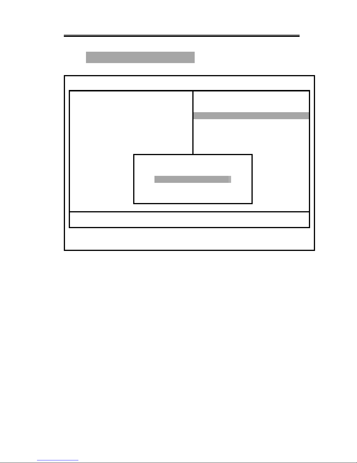
4.11 Load Fall-Safe Defaults
Phoenix – Award BIOS CMOS Setup Utility
Standard CMOS Features Frequency/Voltage Control
Advanced BIOS Features Load Fall-Safe Defaults
Advanced Chipset F Features Load Optimized Defaults
Integrated Peripherals Set Supervisor Password
Power Management word
PnP/PCI Configura Save & Exit Setup
PC Health Status
Load Fall-Safe Defaults (Y/N)?
Exit Without Saving
Esc : Quit ↑ ↓ ← → : Select Item
F10 : Save & Exit Setup
Time, Date, Hard Disk Type………
Page 65
Chapter 4: BIOS Configuration
53
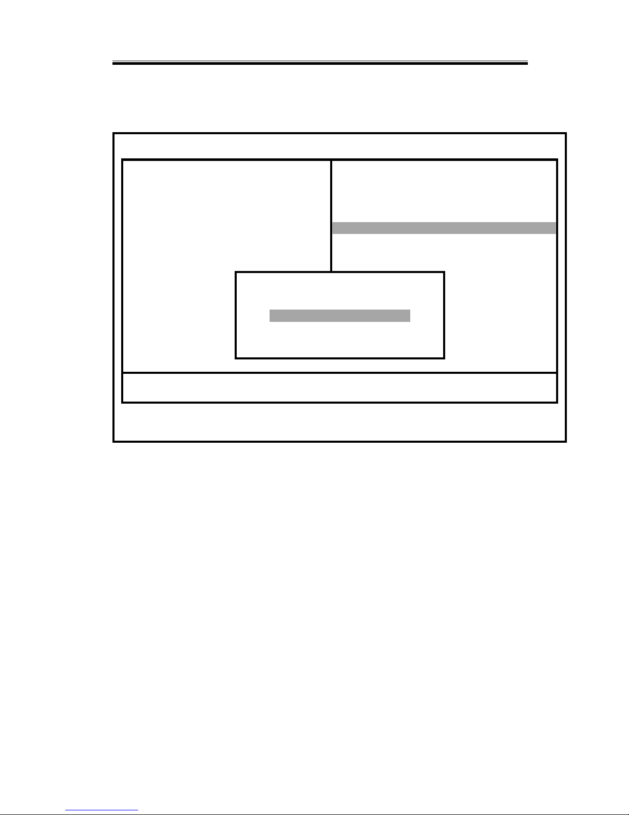
4.12 Load Optimized Defaults
Phoenix – Award BIOS CMOS Setup Utility
Standard CMOS Features Frequency/Voltage Control
Advanced BIOS Features Load Fall-Safe Defaults
Advanced Chipset F Features Load Optimized Defaults
Integrated Peripherals Set Supervisor Password
Power Management word
PnP/PCI Configura Save & Exit Setup
PC Health Status
Load Optimized Defaults (Y/N)?
Exit Without Saving
Esc : Quit ↑ ↓ ← → : Select Item
F10 : Save & Exit Setup
Time, Date, Hard Disk Type………
4.13 Power On Boot
After you made all the changes to the CMOS values, and the
system cannot boot up with the CMOS values selected in
Setup, restart the system by turning it OFF then ON or by
pressing the "RESET" button on the system case. You may
also restart it by simultaneously pressing <Ctrl>, <Alt>, and
<Delete> keys. Upon restarting the system, immediately
press <Insert> to load the BIOS default CMOS value for
boot up.
Page 66

MSC-1610 User’s Manual
54
4.14 BIOS Reference – POST Codes
AWARD BIOS provides all IBM standard Power On Self
Test (POST) routines as well as enhanced AWARD BIOS
POST routines. The POST routines support CPU internal
diagnostics. The POST checkpoint codes are accessible via
the Manufacturing Test Port (I/O port 80h).
Whenever a recoverable error occurs during the POST,
the system BIOS will display an error message
describing the message and explaining the problem in
detail so that the problem can be corrected.
NOTE: POST codes output to the port address 80h typically.
POST
(hex)
Description
C0
1. Turn off OEM specific cache, shadow...
2. Initialize all the standard devices with default values
Standard device includes:
-DMA controller (8237)
-Programmable Interrupt Controller (8259)
-Programmable Interval Timer (8254)
-RTC chip
C1 Auto-detection of onboard DRAM & Cache
C3 1. Test system BIOS checksum
2. Test the first 256K DRAM
3. Expand the compressed codes into temporary DRAM area
including the compressed System BIOS & Option ROMs
C5 Copy the BIOS from ROM into E0000-FFFFF shadow RAM
so that POST will go faster
01-02 Reserved
03 Initialize EISA registers (EISA BIOS only)
04 Reserved
05 1. Keyboard Controller Self-Test
2. Enable Keyboard Interface
06 Reserved
07 Verifies CMOS’s basic R/W functionality
Page 67

Chapter 4: BIOS Configuration
55
POST
(hex)
Description
BE
Program defaults values into chipset according to the
MODBINable Chipset Default Table
08
Test the first 256K DRAM
09
1. Program the configuration register of Cyrix CPU according
to the MODBINable Cyrix Register Table
2. OEM specific cache initialization (if needed)
0A
1. Initialize the first 32 interrupt vectors with corresponding
Interrupt handlers
Initialize INT no from 33-120 with Dummy(Spurious)
Interrupt Handler
2. Issue CPUID instruction to identify CPU type
3. Early Power Management initialization (OEM specific)
0B
1. Verify the RTC time is valid or not
2. Detect bad battery
3. Read CMOS data into BIOS stack area
4. PnP initialization include (PnP BIOS only)
-Create resource map from ESCD
5. Assign IO & Memory for PCI devices (PCI BIOS only)
0C
Initialization of the BIOS Data Area (40 : 0N − 40:FF)
0D
1. Program some of the Chipset values according to
Setup.(Early Setup Value Program)
2. Measure CPU speed for display & decide the system clock
speed
3. Video initialization including Monochrome, CGA,
EGA/VGA. If no display device is found, the speaker will
beep
0E
1. Initialize the APIC (Multi-Processor BIOS only)
2. Test video RAM (If Monochrome display device is found)
3. Shown messages include:
-Award Logo, Copyright string, BIOS Date code & Part No.
-OEM specific sign on messages
-Energy Star Logo (Green BIOS ONLY)
-CPU brand, type & speed
-Test system BIOS checksum (Non-Compress Version only)
0F
DMA channel 0 test
10
DMA channel 1 test
11
DMA page registers test
12-13
Reserved
Page 68

MSC-1610 User’s Manual
56
POST
(hex)
Description
14
Test 8254 Timer 0 Counter 2.
15
Test 8259 interrupt mask bits for channel 1
16
Test 8259 interrupt mask bits for channel 2
17
Reserved
19
Test 8259 functionality
1A-1D
Reserved
1E
If EISA NVM checksum is good, then execute EISA
initialization (EISA BIOS only)
1F-29
Reserved
30
Detect Base Memory & Extended Memory Size
31
1. Test Base Memory from 256K to 640K
2. Test Extended Memory from 1M to the Max. of the memory
32
1. Display the Award Plug & Play BIOS Extension message
(PnP BIOS only)
2. Program onboard super I/O chip (if any) including COM
ports, LPT ports, FDD port. according to setup value
33-3B
Reserved
3C
Set flag to allow users to enter CMOS Setup Utility
3D
1. Initialize Keyboard
2. Install PS2 mouse
3E
Try to turn on Level 2 cache
Note: Some chipset may need to turn on the L2 cache on this
stage. But usually, the cache is turned on later in POST
61h
3F-40
Reserved
BF
1. Program the rest of the Chipset value according to Setup.
(Later Setup Value Program)
2. If auto-configuration is enabled, programmed the chipset
with pre-defined values in the MODBINable Auto-Table
41
Initialize floppy disk drive controller
42
Initialize Hard drive controller
43
If it is a PnP BIOS, initialize serial & parallel ports
44
Reserved
45
Initialize math coprocessor.
46-4D
Reserved
Page 69

Chapter 4: BIOS Configuration
57
POST
(hex)
Description
4E
If any error is detected (such as video, kb...), show all the error
messages on the screen & wait for user to press <F1> key
4F
1. If a password is needed, ask for the password
2. Clear the Energy Star Logo (Green BIOS only)
50
Write all CMOS values currently in the BIOS stack area back
into the CMOS
51
Reserved
52
1. Initialize all ISA ROMs
2. Later PCI initialization (PCI BIOS only)
-assign IRQ to PCI devices
-initialize all PCI ROMs
3. PnP Initialization (PnP BIOS only)
-assign IO, Memory, IRQ & DMA to PnP ISA devices
-initialize all PnP ISA ROMs
4. Program shadows RAM according to the Setup settings
5. Program parity according to Setup setting
6. Power Management Initialization
-Enable/Disable global PM
-APM interface initialization
53
1. If it is NOT a PnP BIOS, initialize serial & parallel ports
2. Initialize time value in the BIOS data area by translating the
RTC time value into a timer tick value
60
Setup the Virus Protection (Boot Sector Protection) function
according to Setup setting
61
1. Try to turn on Level 2 cache
Note: if L2 cache is already turned on in POST 3E, this part
will be skipped
2. Set the boot up speed according to the Setup setting
3. Last chance for Chipset initialization
4. Last chance for Power Management initialization (Green
BIOS only)
5. Show the system configuration table
62
1. Setup daylight saving according to Setup value
2. Program the NUM Lock, typematic rate & typematic speed
according to the Setup setting
63
1. If there is any change in the hardware configuration, update
the ESCD information (PnP BIOS only)
2. Clear the memory that has been used
3. Boot the system via INT 19H
Page 70
MSC-1610 User’s Manual
58
POST
(hex)
Description
FF
System Booting. This means that the BIOS already pass the
control right to the operating system
Unexpected Errors:
POST
(hex)
Description
B0 Interrupt occurs in protected mode.
B1 Unclaimed NMI occurs
4.15 Updating BIOS
You should prepare a diskette for the updated BIOS
program in the package. The update procedures are as
follows:
1. Insert the diskette with the file “AWDFLASH.EXE’ in
drive A or B.
2. Type AWDFLASH under the prompt A or B.
3. The screen will ask you to enter the filename for
programming. Please enter the ‘filename’ for the updated
BIOS that came from your agent. Meanwhile, please type
‘N’ to answer the question ‘Do you want to save BIOS
(y/n)?’ under the bottom of the screen.
4. After that, please type ‘Y’ to answer the question ‘Are you
sure to program (y/n)?’ on the bottom line of the current
screen.
5. Turn off the power after the system updated the BIOS.
6. Turn on the power again.
 Loading...