

Page 1
Please read the instruction handbook before using the printer. Keep it close
to the printer for easy reference.
INSTRUCTION HANDBOOK
Laser Printe
r
DP-2800
Table of Contents
*
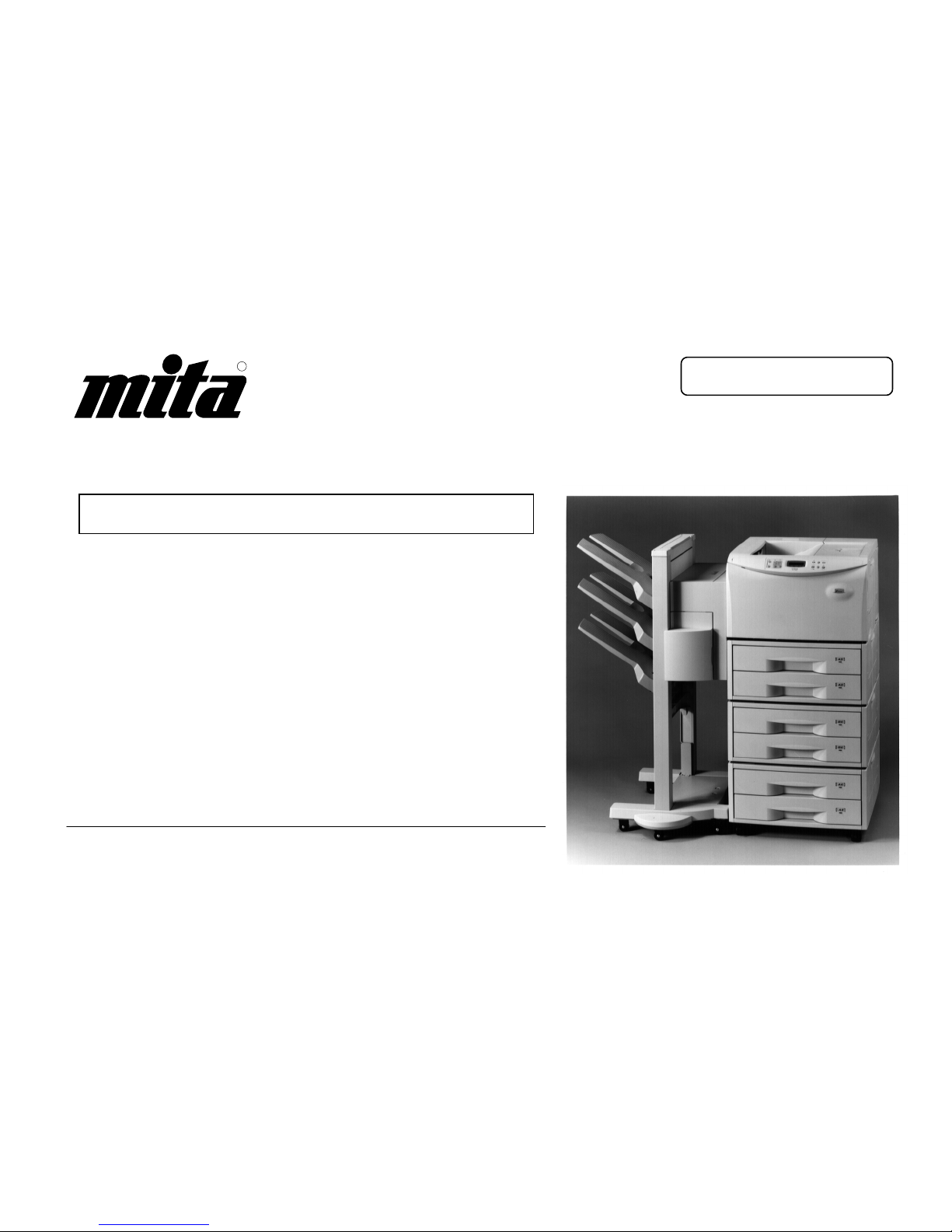
The DP-2800 in this photograph is equipped with two optional paper feeders (ST-1000)
and an optional document finisher (F-8118).
R
Page 2
Introduction
i
Please read the instruction handbook before using the
printer. Keep it close to the printer for easy reference.
The sections of this handbook and parts of the printer marked with
symbols are safety warnings meant to protect the user, other individuals
and surrounding objects, and ensure correct and safe usage of the
printer. The symbols and their meanings are indicated below.
DANGER: Indicates that serious injury or even death will very possibly
result from insufficient attention to or incorrect compliance with the related
points.
WARNING: Indicates that serious injury or even death may result from
insufficient attention to or incorrect compliance with the related points.
CAUTION: Indicates that personal injury or mechanical damage may
result from insufficient attention to or incorrect compliance with the related
points.
Symbols
The symbol indicates that the related section includes safety warnings.
Specific points of attention are indicated inside the symbol.
...........[General warning]
...........[Warning of danger of electrical shock]
...........[Warning of high temperature]
The symbol indicates that the related section includes information on
prohibited actions. Specifics of the prohibited action are indicated inside
the symbol.
...........[Warning of prohibited action]
...........[Disassembly prohibited]
The
●symbol indicates that the related section includes information on
actions which must be performed. Specifics of the required action are
indicated inside the symbol.
...........[Alert of required action]
...........[Remove the power plug from the outlet]
...........[Always connect the printer to an outlet with
a ground connection]
Please contact your service representative to order a replacement if the
safety warnings in the handbook are illegible or if the handbook itself is
missing. (fee required)
Page 3

Introduction
ii
Caution
NO LIABILITY IS ASSUMED FOR ANY DAMAGE CAUSED BY IMPRO PER INSTALLATION.
Notice on Software_____________________________________________________________________________________
SOFTWARE USED WITH THIS PRINTER MUST SUPPORT THE PRINTER’S NATIVE MODE OR ONE OF I TS EMULATION MODES. The
printer is factory set to emulate the HP LaserJet 5Si. The emulation mode can be changed by following the procedures described in Chapter 2.
Notice _______________________________________________________________________________________________
The information in this manual is subject to change without notification. Additional pages may be inserted in future editions. The user is asked to
excuse any technical inaccuracies or typographical errors in the present edition.
No responsibility is assumed if accidents occur while the user is following the instructions in this manual. No responsibility is assumed for defects in
the printer’s firmware (contents of its read-only memory).
This manual, any copyrightable subject matter sold or provided with or in connection with the sale of the page printer, are protected by copyright.
All rights are reserved. Copying or other reproduction of all or part of this manual, any copyrightable subject matter without the prior written consent
of our company is prohibited. Any copies made of all or part of this manual, any copyrightable subject must contain the same copyright notice as
the material from which the copying is done.
Regarding Tradenames_________________________________________________________________________________
PRESCRIBE is a registered trademark of Kyocera Corporation. PRESCRIBE II, PRESCRIBE IIe, KPDL, and KIR are trademarks of Kyocera
Corporation.
Diablo 630 is a product of Xerox Corporation. IBM Proprinter X24E is a product of International Business Machines Corporation. Epson LQ-850 is a
product of Seiko Epson Corporation.
HP LaserJet 5Si is a product of Hewlett-Packard Company. Hewlett-Packard, PCL, and PJL are registered trademarks of Hewlett-Packard
Company. Centronics is a trade name of Centronics Data Computer Corp. PostScript is a registered trademark of Adobe Systems Incorporated.
Macintosh is a registered trademark of Apple computer, Inc. AppleTalk is a trademark of Apple Computer, Inc. Microsoft, Windows, and MS-DOS
are registered trademarks of Microsoft Corporation. Adobe and Acrobat are trademarks of Adobe Systems Incorporated which may be registered in
certain jurisdictions.
This printer uses PeerlessPrint5 to provide the HP LaserJet compatible PCL5 language emulation. PeerlessPrint5 is a trademark of The Peerless
Group, Redondo Beach, CA 90278, U.S.A.
This product was developed using the Tornado™ Real Time Operating System and Tools from Wind River Systems.
Page 4

Introduction
iii
IBM PROGRAM LICENSE AGREEME NT ____________________________________________________________________
THE DEVICE YOU HAVE PURCHASED CONTAINS ONE OR MORE SOFTWARE PROGRAMS (“PROGRAMS”) WHICH BELONG TO
INTERNATIONAL BUSINESS MACHINES CORPORATION (“IBM”). THIS DOCUMENT DEFINES THE TERMS AND CONDITIONS UNDER
WHICH THE SOFTWARE IS BEING LICENSED TO YOU BY IBM. IF YOU DO NOT AGREE WITH THE TERMS AND CONDITIONS OF THIS
LICENSE, THEN WITHIN 14 DAYS AFTER YOUR ACQU ISITION OF THE DEVICE YOU MAY RETURN THE DEVI CE FOR A FULL REFUND.
IF YOU DO NOT SO RETURN THE DEVICE WITHIN THE 14 DAYS, THEN YOU WILL BE ASSUMED TO HAVE AGREED T O THESE TERMS
AND CONDITIONS.
The Programs are licensed not sold. IBM, or the applicable IBM country organization, grants you a license for the Programs only in the country
where you acquired the Programs. You obtain no rights other than those granted you under this license.
The term “Programs” means the original and all whole or partial copies of it, including modified copies or portions merged into other programs. IBM
retains title to the Programs. IBM owns, or has licensed from the owner, copyrights in the Programs.
1. License
Under this license, you may use the Programs only with the device on which they are installed and transfer possession of the Programs and the
device to another party.
If you transfer the Programs, you must transfer a copy of this license and any other documentation to the other party. Your license is then
terminated. The other party agrees to these terms and conditions by its first use of the Program.
You may not:
1) use, copy, modify, merge, or transfer copies of the Program except as provided in this license;
2) reverse assemble or reverse compile the Program; or
3) sublicense, rent, lease, or assign the Program.
2. Limited Warranty
The Programs are provided “AS IS”.
THERE ARE NO OTHER WARRANTIES COVERING THE PROGRAMS (OR CONDITIONS), EXPRESS OR IMPLIED, INCLUDING, BUT NOT
LIMITED TO, THE IMPLIED WARRANTIES OF MERCHANTABILITY AND FITNESS FOR A PARTICULAR PURPOSE.
Some jurisdictions do not allow the exclusion of implied warranties, so the above exclusion may not apply to you.
SUPPLEMENT TO AGREEMENT FOR SOFTWARE BUNDLING AND DISTRIBUTION FOR ALDC
Page 5

Introduction
iv
3. Limitation of Remedies
IBM’s entire liability under this license is the following;
1) For any claim (including fundamental breach), in any form, related in any way to this license, IBM’s liability will be for actual damages only and
will be limited to the greater of:
a) the equivalent of U.S. $25,000 in your local currency; or
b) IBM’s then generally available license fee for the Program
This limitation will not apply to claims for bodily injury or damages to real or tangible personal property for which IBM is legally liable.
IBM will not be liable for any lost profits, lost savings, or any incidental damages or other economic consequential damages, even if IBM, or its
authorized supplier, has been advised of the possibility of such damages. IBM will not be liable for any damages claimed by you based on any third
party claim. This limitation of remedies also applies to any developer of Programs supplied to IBM. IBM’s and the developer’s limitations of
remedies are not cumulative. Such developer is an intended beneficiary of this Section. Some jurisdictions do not allow these limitations or
exclusions, so they may not apply to you.
4. General
You may terminate your license at any time. IBM may terminate your license if you fail to comply with the terms and conditions of this license. In
either event, you must destroy all your copies of the Program. You are responsible for payment of any taxes, including personal property taxes,
resulting from this license. Neither party may bring an action, regardless of form, more than two years after the cause of action arose. If you
acquired the Program in the United States, this license is governed by the laws of the State of New York. If you acquired the Program in Canada,
this license is governed by the laws of the Province of Ontario. Otherwise, this license is governed by the laws of the country in which you acquired
the Program.
Page 6

Introduction
v
Typeface Trademark Acknowledgement____________________________________________________________________
All resident fonts in this printer are licensed from Bitstream Inc., Cambridge, Massachusetts, U.S.A.
Dutch801, Swiss742, Incised901, ZapfCalligraphic801, ZapfHumanist601, OriginalGaramond, and Chianti are trademarks of Bitstream Inc.
Centutry Schoolbook, Stymie, and Cooper-Black are trademarks of Kingsley-ATF Type Corporation.
ITC ZapfDingbats, ITC Souvenir, ITC Benguiat, and ITC Bookman are registered trademarks of International Type-face Corporation.
Revue is a trademark of Esselte Pendaflex Corporation in the U.S., Letraset Canada Ltd. in Canada, and Esselte Letraset Ltd. elsewhere.
Bitstream Sublicense Agreement _________________________________________________________________________
FONTWARE/TrueDoc developed by BITSTREAM INC. is provided as part of this Printer by our company under license. We, as a Licensee of
BITSTREAM, grants you, the Sublicensee, non-exclusive right to use FONTWARE/TrueDoc installed in this Printer, if you agree to and at all times
comply with the following items:
1. Ownership
As the Sublicensee, you own the Printer in which FONTWARE/TrueDoc is originally installed, but BITSTREAM retains title to and ownership in the
software program of FONTWARE/TrueDoc. The Sublicense is not a sale of the original software program of FONTWARE/TrueDoc or any portion
or copy of it.
2. Copy Restrictions
FONTWARE/TrueDoc is copyrighted. Unauthorized copying of FONTWARE/TrueDoc even if modified, merged, or included with other software, is
expressly forbidden. You may be held legally responsible for any copyright in-fringement.
3. Unauthorized Use
FONTWARE/TrueDoc may not be removed, disclosed and transferred to any third party for any length of time without the prior written consent of
our company or BITSTREAM. Also, you may not modify, adapt, translate, reverse engineer, decompile, or create derivative works based on
FONTWARE/TrueDoc.
4. Term
This agreement should remain in full force and effect forever thereby allowing the Sublicensee to use the FONTWARE/TrueDoc forever unless the
Sublicensee violates the terms of paragraphs 2. or 3. above. In the event of such violation, this agreement will terminate automatically without
notice from us. Upon termination, you should destroy FONTWARE/TrueDoc and all copies of them, in part and in whole, including modified copies,
if any.
Page 7

Introduction
vi
FCC statement
This device complies with Part 15 of the FCC Rules. Operation is subject to the following two
conditions: (1) This device may not cause harmful interference, and (2) this device must accept any
interference received, including interference that may cause undesired operation.
This equipment has been tested and found to comply with the limits for a Class B digital device,
pursuant to Part 15 of the FCC Rules. These limits are designed to provide reasonable protection
against harmful interference in a residential installation. This equipment generates, uses, and can
radiate radio frequency energy and, if not installed and used in accordance with the instructions, may
cause harmful interference to radio communications. However, there is no guarantee that interference
will not occur in a particular installation. If this equipment does cause harmful interference to radio or
television reception, which can be determined by turning the equipment off and on, the user is
encouraged to try to correct the interference by one or more of the following measures:
·
Reorient or relocate the receiving antenna.
·
Increase the separation between the equipment and receiver.
·
Connect the equipment into an outlet on a circuit different from that to which the receiver is
connected.
·
Consult the dealer or an experienced radio/TV technician for help.
Changes or modifications not expressly approved by the manufacturer for compliance could void the
user’s authority to operate the equipment.
Shielded circular cable should be used for interfacing with the computer.
Caution to user
Any modification without prior permission may cause harmful interference.
If any modification/change is introduced to this equipment without prior permission, we as the
manufacturer cannot guarantee compliance with FCC rules.
Page 8

Introduction
vii
To use equipment which does not comply with FCC rules is prohibited.
The printer may be optionally installed with the following units:
Conforming to the Class B limits
·
ST-1000 Paper Feeder (500 sheets)
·
EF-100 Envelope Feeder
·
UF-100 Universal Feeder
·
AD-31 Duplexer
·
F-8130 Bulk Paper Stacker (3000 sheets)
·
F-8118 Document Finisher (1800 sheets)
·
KPDL Font Rom KPDL Upgrade Kit
·
HD-101 Hard Disk Unit
Page 9

Introduction
viii
Interface connectors
Important note on the interface connectors
Be sure to turn off printer power before connecting or disconnecting an interface cable* to the printer.
For protection against static discharge which may be applied to the printer’s internal electronics
through the interface connector(s), keep any interface connector which is not in use capped using the
protective cap supplied.
* Use shielded interface cable.
Safety information
Laser safety
This printer is certified as a Class 1 laser product under the U.S. Department of Health and Human
Services (DHHS) Radiation Performance Standard according to Radiation Control for Health and
Safety Act of 1968. This means that the printer does not produce hazardous laser radiation. Since
radiation emitted inside the printer is completely confined within protective housings and external
covers, the laser beam cannot escape from the printer during any phase of user operation.
Laser notice
This printer is certified in the U.S. to conform to the requirements of DHHS 21 CFR Subchapter for
Class I (1) laser products, and elsewhere is certified as a Class I laser product conforming to the
requirements of IEC 825.
Page 10
Introduction
ix
*
Use of controls or adjustments or performance of procedures other than those specified
herein may result in hazardous radiation exposure.
CAUTION
Laser radiation when open. DO NOT STARE INTO BEAM OR VIEW
DIRECTLY WITH OPTICAL INSTRUMENTS.
Page 11

Introduction
x
CDRH regulations
The Center of Devices and Radiological Health (CDRH) of the U.S. Food and Drug Administration
implemented regulations for laser products on August 2, 1976. These regulations apply to laser
products manufactured after August 1, 1976. Compliance is mandatory for products marketed in the
United States. A label indicating compliance with the CDRH regulations must be attached to laser
products marketed in the United States.
Ozone concentration
The printer generates ozone gas (O3) which may concentrate in the place of installation and cause an
unpleasant smell. To minimize concentration of ozone gas to less than 0.1 ppm, we recommend you
not to install the printer in a confined area where ventilation is blocked.
Page 12

Introduction
xi
Declaration of Conformity (U.S.A.)
Model Number: DP-2800
Trade Name: Mita
Responsible Party: MITA COPYSTAR AMERICA, INC.
Address: 225 Sand Road, P.O.Box 40008
Fairfield New Jersey 07004-0008
Telephone number: 973-808-8444
Fax number: 973-882-6000
This device complies with Part 15 of the FCC Rules, Operation is subject to the following two
conditions: (1) This device may not cause harmful interference, and (2) this device must accept any
interference received, including interference that may cause undesired operation.
Page 13

Introduction
xii
Canadian Department of Communications compliance statement
This Class B digital apparatus complies with Canadian ICES-003.
Avis de conformité aux normes du ministère des Communications du Canada
Cet appareil numérique de la classe B est conforme à la norme NMB-003 du Canada.
Safety & EMI Requirements
IEC IEC950:1991 (+A1+A2+A3) / (IEC825-1:1993)
Laser requirements (U.S.A.) FDA Title 21 CFR, Chapter 1, Subchapter J
UL UL 1950: 3
rd
edition
CAN/CSA CSA C22.2 No.950- 95 3
rd
edition
FCC Rules 47 CFR, Parts 2 and 15, subpart B, Class B
CDC ICES-003 (3
rd
): 1997, Class B
Page 14

Introduction
xiii
Disclaimer
We shall have no liability or responsibility to customers or any other person or entity with respect to
any liability, loss or damage caused or alleged to be caused directly or indirectly by equipment sold or
furnished by us, including but not limited to, any interruption of service, loss of business or anticipatory
profits, or consequential damages resulting from the use or operation of the equipment or software.
Prolonged Non-Use and Moving the Printer
Prolonged Non-use
If you ever leave the printer unused for a long period of time, remove the power cord from the wall
outlet.
We recommend you consult with your dealer about the additional actions you should take to avoid
possible damages that may occur when the printer is used next time.
Moving the Printer
When you move the printer:
·
Move it gently.
·
Keep it as level as possible, to avoid spilling toner inside the printer.
·
If you ship the printer, remove the developer unit and ship it separately. Be sure to consult your
dealer before attempting long-distance transportation of the printer.
Page 15

Introduction
xiv
ENERGY STAR
SM
As an ENERGY STAR Partner, Mita (Mita Copyst ar Am er ica, Inc.) has determined that t his pr oduct
meets the ENERGY STAR guidelines for energy efficiency.
* ENERGY STAR is a U.S. regist er ed mark.
Page 16

Introduction
xv
Introduction
The laser printer has many extremely desirable features. It was designed to make a contribution to a
cleaner environment as well as to represent the latest generation of page printer technology.
Superb print quality
With an amorphous silicon drum, microfine ceramic toner, and the latest technology from us such as
KIR function*, this laser printer delivers superb print quality and clarity. (*See page 2-45.)
Ultra long life modules
The main modules in this laser printer such as the drum, developer unit and fuser unit, which are
disposable in conventional printers, are specifically designed for extraordinarily long life and need no
periodic replacement. The drum is made of amorphous silicon which is environmentally benign. The
only maintenance regularly needed therefore is to replenish the toner supply in the developer
approximately every 25,000 printed pages (A4 portrait at a printing rate of approximately 5%) and to
clean some parts inside the printer.
Amorphous silicon drum
Our own unique ceramics technology has led to the development of an extremely hard and durable
drum with extraordinarily long service life. Also, the drum has several excellent photoconductive
properties, such as stability and reliability in varying temperatures, resistance to heat and solvent, etc.,
thus providing superb high resolution printing.
High speed printing
A3-size pages typically print at a rate of 16 pages per minute, B4 at 18 pages per minute, and A4
(landscape feed) at 28 pages per minute (when printing multiple copies of the same page). (Actual
printing time varies depending on what is being printed.)
Page 17

Introduction
xvi
Environmentally benign waste parts
The toner container is made out of a benign, flammable material. (Be sure to dispose of containers
according to local laws and regulations.)
Large paper capacity cassettes
Equipped at the bottom with a two-stage paper feeder, each paper cassette can hold approximately
500 sheets (80 g/m
2
, 0.11 mm thickness). There is also a multi-purpose tray with a capacity of
approximately 100 sheets. Paper can be output on a face-down output tray or an optional face-up
output tray. Either output tray can stack approximately 500 sheets of paper.
Scalable printing
This printer allows reductions between various paper sizes using the page setup function.
Bitmapped and scalable typefaces
In addition to its 79 internal bitmap fonts, the printer provides 45 fully-scalable resident typefaces that
are equivalent to HPLJ fonts. The scalable typefaces can be used at any size desired up to
999.75 points, in 0.25-point increments.
A new printer control language, PRESCRIBE II e
PRESCRIBE IIe includes advanced graphics capabilities that allow you to print any conceivable
outline shape or solid form. Also provided are a variety of special effects, such as patterned fills, grayscale shading, a user-accessible print image model, and multiple page orientations and print directions
within the same page.
Page 18

Introduction
xvii
PDF417 two-dimensional bar code
The printer includes the capability that allows the user to implement the two-dimensional stacked bar
code symbology, PDF417, or Portable Data File 417. This expanded functionality is achieved by using
the PRESCRIBE IIe language commands.
Automatic rotation of fonts and graphics
Images and scalable fonts are automatically rotated to match the page orientation.
A wide variety of internal symbol sets
The printer supports most Hewlett-Packard LaserJet 5Si compatible symbol sets for both bitmap and
scalable fonts.
Display of printer messages in any of three languages
English, French, or German. As an option it is also possible to download the messages in other
languages. Please contact your dealer.
Memory card slot for option fonts, macros, forms, etc.
Data in the memory card can be selectively read from the printer’s control panel.
Simple Network Management Protocol (SNMP) compliance
Offers network managers complete open system network management.
Page 19

Introduction
xviii
Large memory capacity
This printer comes standard equipped with 4 MB of memory. This can be extended up to 68 MB of
memory through optional expansion of memory.
Expandable interface
Equipped with slots for installing optional interfaces, the interfaces of this printer can be expanded to
meet the specific operating environment.
Options
The following options are available for this printer:
ST-1000 Paper feeder
(for installation below, 500-sheet capacity [0.11-mm paper thickness] x 2)
EF-100 Envelope feeder
UF-100 Universal feeder
AD-31 Duplex printing unit
F-8130 Bulk paper stacker (3000-sheet capacity)
F-8118 Document finisher (1800-sheet capacity, includes staple function)
KPDL Font Rom KPDL upgrade kit
HD-101 Hard disk unit
CA-28 Caster kit
Page 20

Introduction
xix
Contents
Chapter 1 Safetyguards and Installing the Page Printer...............1-1
Caution Labels.........................................................................................................1- 2
Installation Precautions............................................................................................ 1- 3
Precautions for use.................................................................................................. 1- 5
Unpacking and Inspection............................................................................................ 1- 7
Moving the Printer........................................................................................................ 1-10
Names of Parts ............................................................................................................ 1-11
Setup and Connections................................................................................................ 1-13
The Multi-Purpose Tray ............................................................................................... 1-36
Expanding Memory...................................................................................................... 1-42
Chapter 2 Operating the Page Printer............................................2-1
Control panel................................................................................................................ 2- 2
Operating Procedures.................................................................................................. 2-11
Mode Selection Menu .................................................................................................. 2-24
Configuring Interfaces.................................................................................................. 2-27
Emulation Selection ..................................................................................................... 2-28
Reduction (Page Set)................................................................................................... 2-29
Memory Cards ............................................................................................................. 2-32
Sleep Timer Setting...................................................................................................... 2-43
Dumping Received Data.............................................................................................. 2-44
KIR Level...................................................................................................................... 2-45
Ecoprint Mode.............................................................................................................. 2-47
Resource Protection .................................................................................................... 2-48
Adjusting the Print Density........................................................................................... 2-49
Setting the Audio Warning (Buzzer)............................................................................. 2-49
Page 21

Contents
xx
Chapter 3 Fonts...............................................................................3-1
Bitmap and Scalable Fonts.......................................................................................... 3- 2
List of Fonts.................................................................................................................. 3- 3
Symbol Set................................................................................................................... 3- 8
Chapter 4 Maintenance...................................................................4-1
Toner Container Replacement..................................................................................... 4- 2
Cleaning....................................................................................................................... 4-10
Chapter 5 Troubleshooting............................................................. 5-1
General Guide.............................................................................................................. 5- 2
Print Quality Problems ................................................................................................. 5- 4
Indicators and Messages............................................................................................. 5- 8
Correcting a Paper Jam............................................................................................... 5-16
Chapter 6 Symbol Set Tables......................................................... 6-1
Appendix A Printer Specifications.................................................A-1
Appendix B Paper Selection...........................................................B-1
Appendix C Host Computer Interface............................................C-1
Index......................................................................................... INDEX-1
Mode Select Menu.................................................................Last page
Page 22

Chapter 1 Safetyguards and Installing the Page Printer
1- 1
Chapter 1
Safetyguards and
Installing the Page
Printer
This chapter uses illustrations to explain the names of parts of this
printer, how to use it, its environmental requirements, and how to
install it.
Caution Labels..................................................................... 1- 2
Installation Precautions........................................................ 1- 3
Precautions for use.............................................................. 1- 5
Unpacking and Inspection ....................................................... 1- 7
Moving the Printer.................................................................... 1-10
Names of Parts........................................................................ 1-11
Setup and Connections ........................................................... 1-13
The Multi-Purpose Tray........................................................... 1-36
Expanding Memory.................................................................. 1-42
Page 23
Caution Lables
1-2
Caution Labels
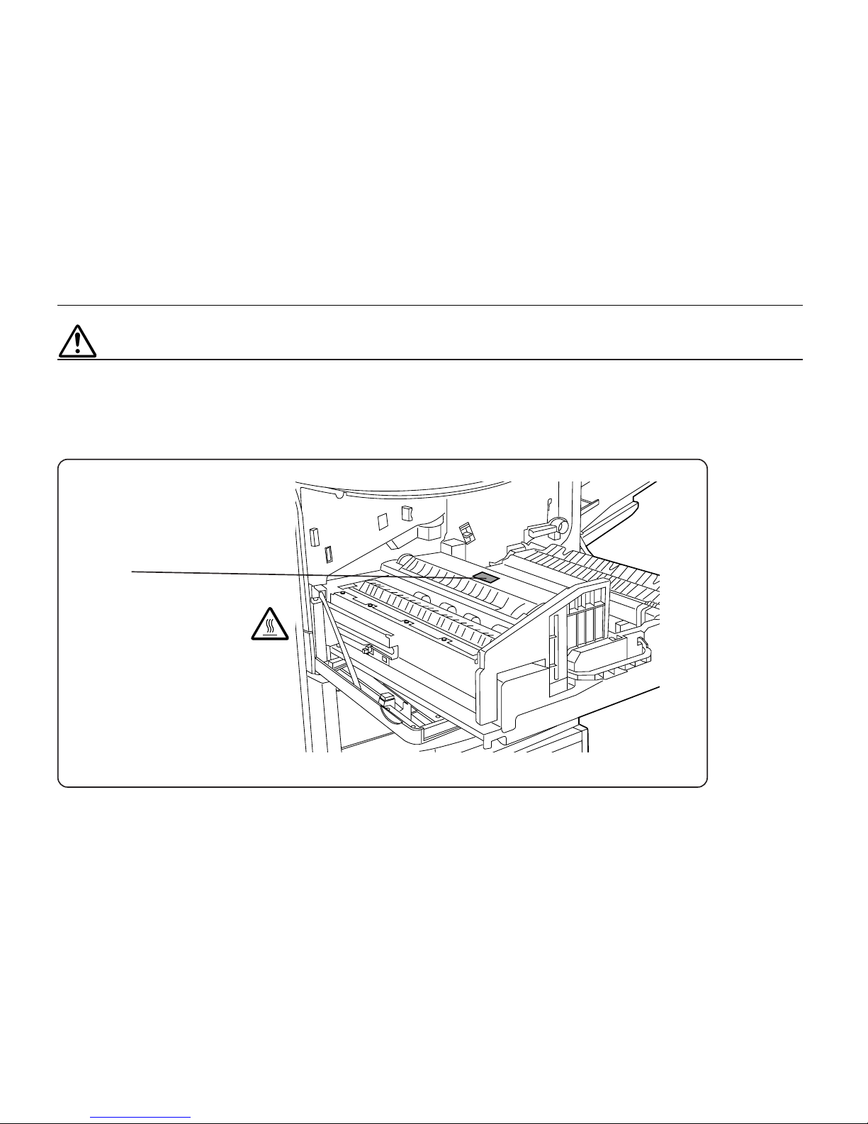
Caution labels have been attached to the printer at the following locations for
safety purposes. BE SUFFICIENTLY CAREFUL to avoid fire or electric shock
when removing a paper jam or when replacing toner.
Label 1
High temperature inside. Do not
touch parts in this area, because
there is a danger of getting
burned. ........................................
NOTE: DO NOT remove these labels.
Page 24
Chapter 1 Safetygaurds and Installing the Page Printer
1-3
■ Environment
CAUTION
• Avoid placing the printer on or in locations which are unstable or
not level. Such locations may cause the printer to fall down or fall
over. This type of situation presents a danger of personal injury
or damage to the printer. ................................................................
• Avoid locations with humidity or dust and dirt. If dust or dirt
become attached to the power plug, clean the plug to avoid the
danger of fire or electrical shock. ...................................................
• Avoid locations near radiators, heaters, or other heat sources, or
locations near flammable items, to avoid the danger of fire...........
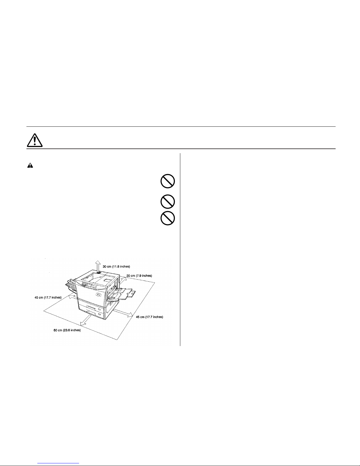
• To keep the printer cool and facilitate changing of parts and
maintenance, allow access space as shown below.
Leave adequate space, especially around the rear cover, to allow
air to be properly ventilated out of the printer.
Other precautions
• Adverse environmental conditions may affect the safe operation and
performance of the printer. Install in an air-conditioned room
(recommended room temperature: around 20°C, humidity: around 65%RH)
and avoid the following locations when selecting a site for the printer.
.
Avoid locations near a window or with exposure to direct sunlight.
.
Avoid locations with vibrations.
.
Avoid locations with drastic temperature fluctuations.
.
Avoid locations with direct exposure to hot or cold air.
.
Avoid poorly ventilated locations.
.
Ammonia or other harmful fumes. (If you are planning to fumigate the
room, or make liberal use of insecticide, remove the printer first!)
.
Low air pressure, e.g., located more than 2000 meters (6500 feet) above
sea level.
• The printer will work best if it is installed in a location that is:
.
Near the computer
If the parallel interface is used to connect the printer to the computer, the
connecting cable should be shielded type and not be longer than 3
meters (10 feet).
.
Level and well supported
Place the printer on a sturdy table or desk. Do not place the printer on an
unstable cart, stand, or table. The printer may fall, causing injury, or
serious damage to the printer.
Installation Precautions
Page 25
Installation Precautions
1-4
■ Power supply/Grounding the printer
WARNING
• DO NOT use a power supply with a voltage other than that
specified. Avoid multiple connections in the same outlet. These
types of situations present a danger of fire or electrical shock.......
• Plug the power cord securely into the outlet. If metallic objects
come in contact with the prongs on the plug, it may cause a fire
or electric shock. ............................................................................
• Always connect the printer to an outlet with a ground connection
to avoid the danger of fire or electrical shock in case of an
electric short. If an earth connection is not possible, contact your
service representative. ..................................................................
Other precautions
• Connect the power plug to the closest outlet possible to the
printer.
• Near an AC wall outlet, preferably one that can be used for the
printer alone .
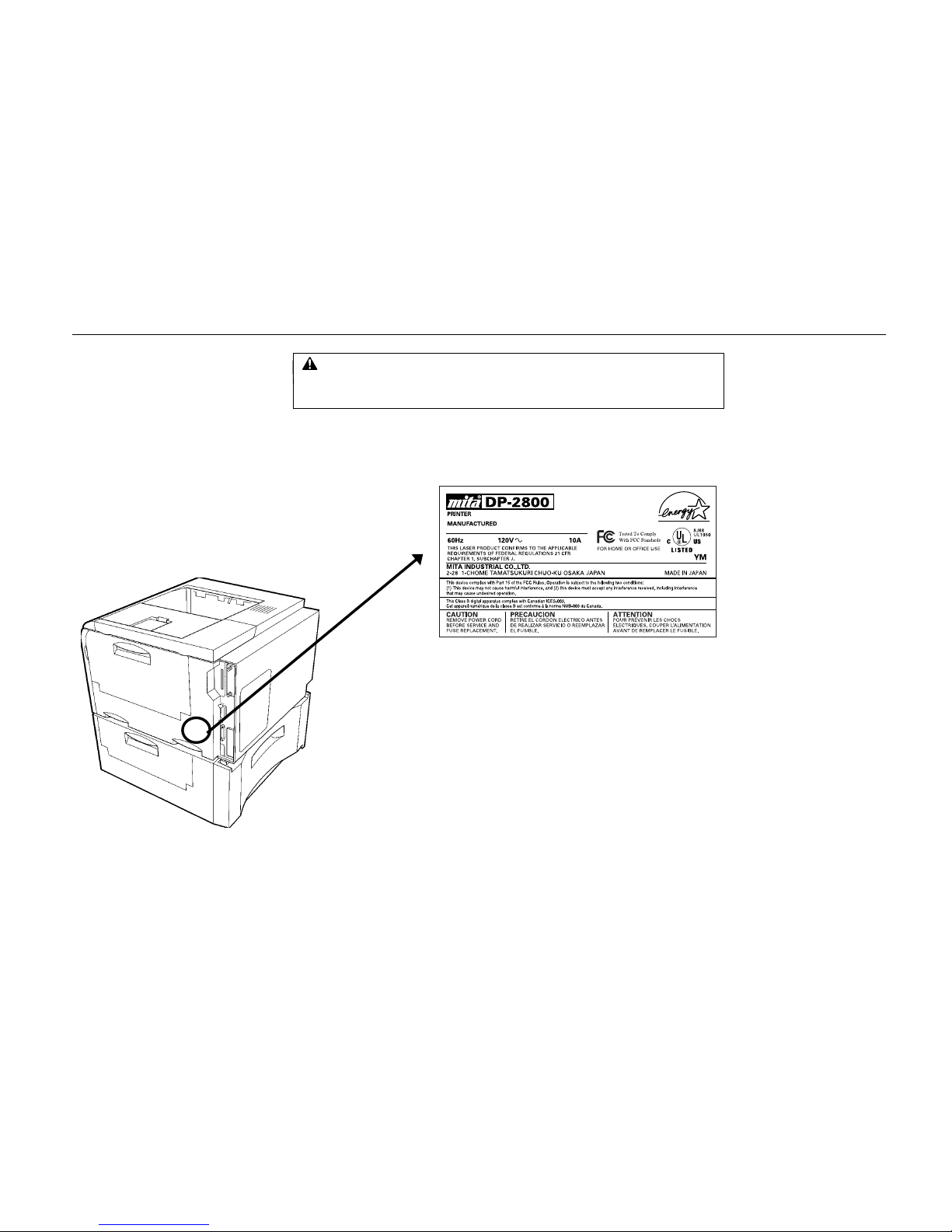
• Only use this printer under the voltage listed on the serial No.
label attached to the rear panel of the printer.
• The outlet should be earthed, or an adapter should be used.
• If an extension cord is used, the total length of the power cord
plus extension should be 5 meters (17 feet) or less.
• The printer should not be on the same power circuit as an air
conditioner, fluorescent light, copier, or shredder, because these
devices generate electrical noise on the power line. If it must
share a power circuit with equipment like this, a high-frequency
noise filter or isolation transformer is advisable.
(Filters and transformers are available commercially.)
■ Handling of plastic bags
WARNING
• Keep the plastic bags that are used with the printer away from
children. The plastic may cling to their nose and mouth causing
suffocation.......................................................................................
• If the power from the outlet itself appears to be unstable, a line stabilizer
should be used. In places where the voltage tends to fluctuate, it may be
necessary to install a voltage regulator.
• As the disconnect device is not incorporated in the printer's AC primary
circuit, an easily accessible socket outlet must be provided near the
equipment.
• If the printer is used with the optional bulk paper stacker (F-8130) or
document finisher (F-8118), in order to avoid short-circuiting, it should be
ensured that these devices are plugged securely into their respective
power outlets.
• Be sure to connect the ground wire for the printer's power supply to the
ground terminal of the power outlet, to a copper pole buried at least 65 cm
(25 inches) in the ground, or to a water pipe approved by the water
department for use as a ground.
• Never use a gas pipe as a ground, as this may result in fire.
Page 26
Chapter 1 Safetygaurds and Installing the Page Printer
1-5
■ Cautions when using the printer
WARNING
• DO NOT place metallic objects or containers with water (flower
vases, flower pots, cups, etc.) on or near the printer. This type of
situation presents a danger of fire or electrical shock should they
fall inside.........................................................................................
• DO NOT remove any of the covers from the printer as there is a
danger of electrical shock from high voltage parts inside the
printer..............................................................................................
• DO NOT damage, break or attempt to repair the power cord.
DO NOT place heavy objects on the cord, pull it, bend it
unnecessarily or cause any other type of damage.
These types of situations present a danger of fire or electrical
shock. .............................................................................................
• NEVER attempt to repair or disassemble the printer or its parts
as there is a danger of fire, electrical shock or damage to the
laser. If the laser beam escapes, there is a danger of it causing
blindness.........................................................................................
• If the printer becomes excessively hot, smoke appears from the
printer, there is an odd smell, or any other abnormal situation
occurs, there is a danger of fire or electrical shock. Turn the
power switch OFF (O) immediately, remove the power plug from
the outlet and contact your service representative.........................
• If anything harmful (paper clips, water, other fluids, etc.) falls into
the printer, turn the power switch OFF (O) immediately. Next,
remove the power plug from the outlet to avoid the danger of fire
or electrical shock. Then contact your service representative. ......
• When adding memory, ALWAYS remove the power plug from the
outlet. If this operation is performed with the power still attached,
there is a danger of electrical shock...............................................
• DO NOT remove or connect the power plug with wet hands, as
there is a danger of electrical shock. .............................................
• For safety purposes, ALWAYS remove the power plug from the
outlet when cleaning the main charger............................................
• ALWAYS contact your service representative for maintenance or
repair of internal parts......................................................................
CAUTION
• DO NOT pull the power cord when removing it from the outlet. If
the power cord is pulled, the wires may become broken and there
is a danger of fire or electrical shock. (ALWAYS grasp the power
plug when removing the power cord from the outlet.)......................
• ALWAYS remove the power plug from the outlet when moving the
printer. If the power cord is damaged, there is a danger of fire or
electrical shock.................................................................................
• If the printer will not be used for a short period of time (overnight,
etc.), turn the power switch OFF (O).
If it will not be used for an extended period of time (vacations,
etc.), remove the power plug from the outlet for safety purposes
during the time the printer is not in use. ..........................................
• ALWAYS hold the designated parts only when lifting or moving
the printer.........................................................................................
• For safety purposes, ALWAYS remove the power plug from the
outlet when performing cleaning operations.....................................
Precautions for use
Page 27
Precautions for use
1-6
• If dust accumulates within the printer, there is a danger of fire or
other trouble. It is therefore recommended that you consult with
your service representative in regard to cleaning of internal parts.
This is particularly effective if accomplished prior to seasons of
high humidity. Consult with your service representative in regard
to the cost of cleaning the internal parts of the printer....................
■ Cautions when handling consumables
CAUTION
• Avoid inhalation, ingestion, skin or eye contact. If ingestion
occurs, dilute stomach contents thoroughly with water and seek
medical treatment. If skin contact occurs, wash with soap and
water. If contact with eyes occurs, flush thoroughly with water
and seek medical treatment...........................................................
• Prolonged inhalation of excessive dusts may cause lung
damage. Use of this product, as intended, does not result in
inhalation of excessive dusts. ........................................................
• Do not incinerate toner and toner containers. Dangerous sparks
may cause burn..............................................................................
• Keep away from children................................................................
Other precautions
• Always read the safety instructions which are included in the box or printed
on the container when handling consumables.
• Dispose of the toner or toner containers in accordance with Federal, State
and Local rules and regulations.
• Store consumables in a cool, dark location.
• If the printer will not be used for an extended period of time, remove the
paper from the cassette, return it to its original package and reseal it.
Page 28
Chapter 1 Safetyguards and Installing the Page Printer
1- 7
Unpacking and Inspection
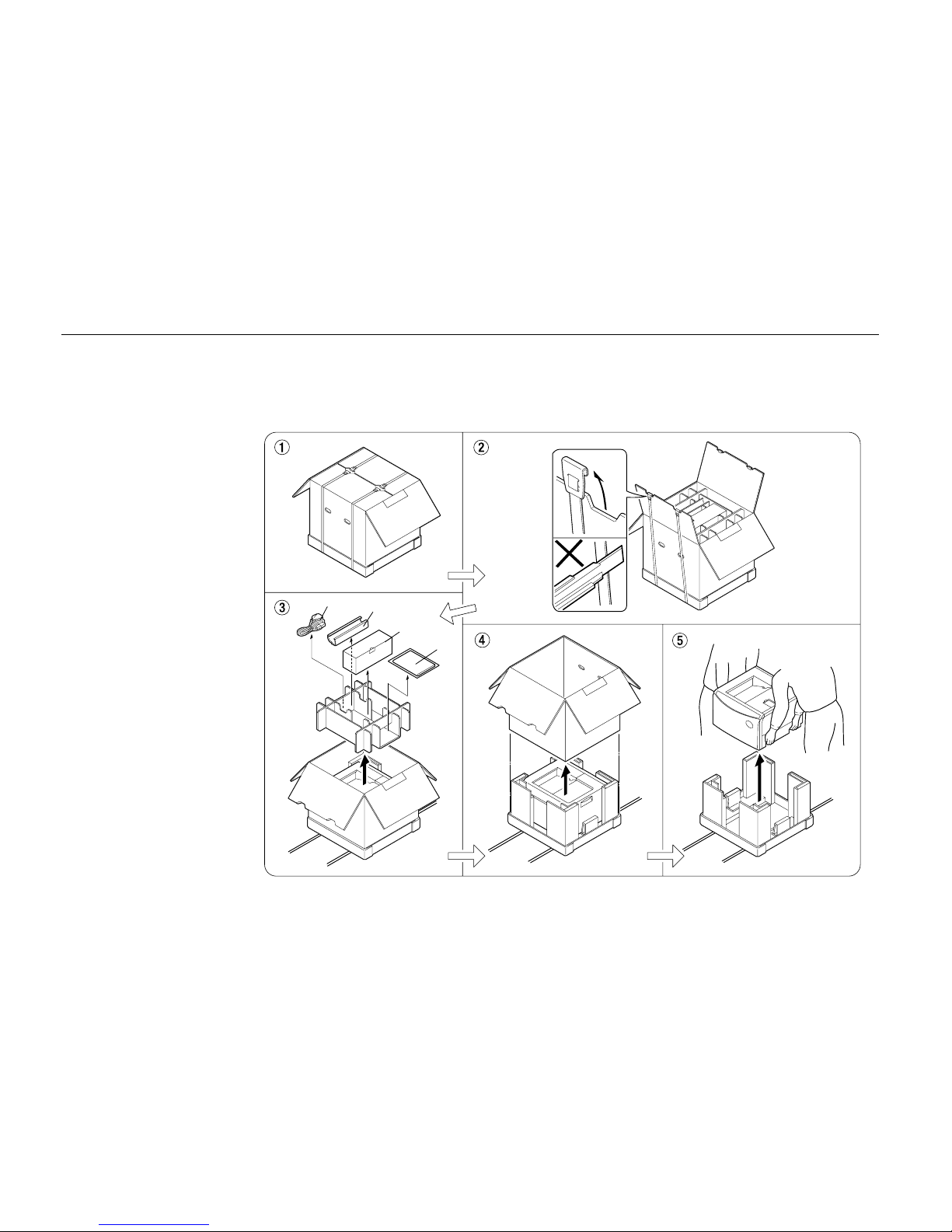
Remove the printer from the package according to the steps given below. (See figure on next page.)
After removing the printer, check that nothing is missing against the list of packaged contents.
1.
Place the box containing the printer on a flat, stable surface.
2.
Remove the INSTRUCTION HANDBOOK, Toner Kit and other items located on top of the spacer
and remove the spacer.
3.
Carefully remove the printer.
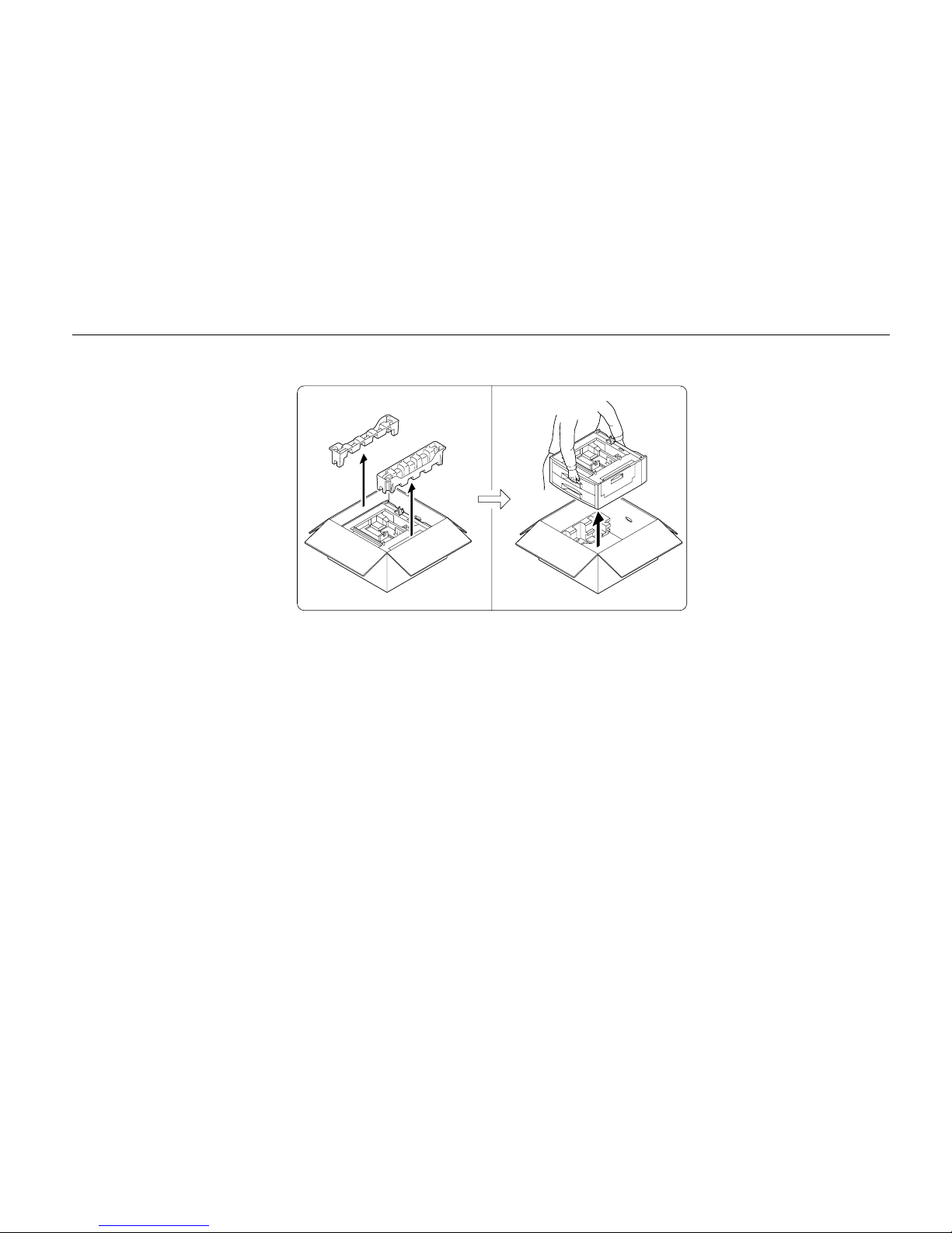
List of packaged contents
The printer and paper feeder are packaged in separate boxes.
CAUTION
Be sure that two or more people unpack and install the printer. Be very careful as the
printer is heav
y
and can hurt your back.
Page 29
Unpacking and Inspection
1- 8
Contents of Printer Box and How to Remove Them
(1) Power Cord
(2) Drum Unit Cover*
(3) Toner Kit (toner container, cleaning cloth)
(4) INSTALLATION HANDBOOK, CD-ROM contains INSTRUCTION HANDBOOK, printer drivers, etc.
Remove the
tape used for
packaging as
shown in the
diagram rather
than cutting with
a cutter. This
tape can be
reused when
repackaging the
printer.
* This drum unit cover is neces s ary
during maintenance to remove
the drum unit.
(1)
(2)
(3)
(4)
Page 30
Chapter 1 Safetyguards and Installing the Page Printer
1- 9
How to Remove the Paper Feeder
Page 31
Moving the Printer
1- 10
Moving the Printer
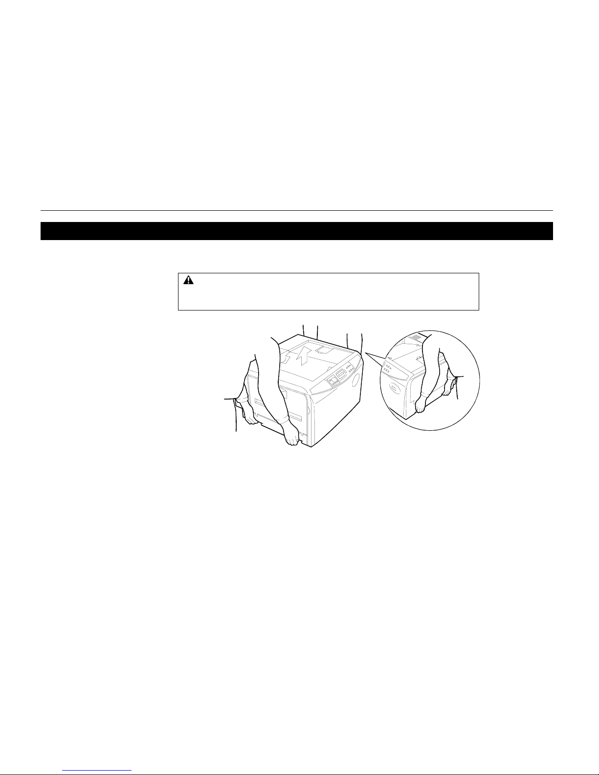
Note the following items when moving the printer.
Be sure to lift the printer gently, keeping it horizontal, to prevent toner from soiling the inside of the
printer.
When transporting the printer a long distance, contact your dealer from which you purchased the
printer.
CAUTION
Be sure that two or more people lift the printer. Grasp the handholds indicated
in the figure below and lift carefully so as not to hurt your back.
Page 32
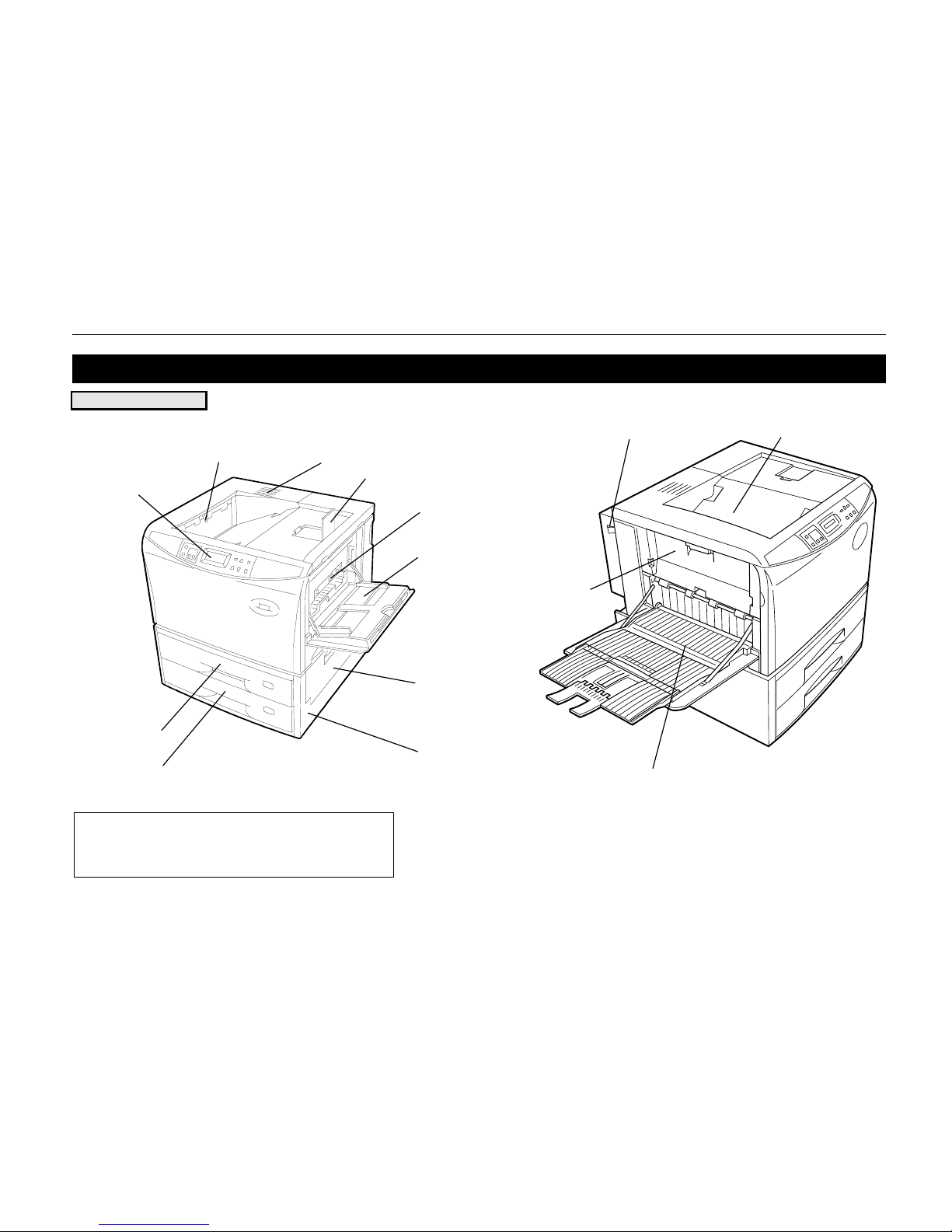
Chapter 1 Safetyguards and Installing the Page Printer
1- 11
Names of Parts
Front View/Side View
Paper Full Sensor
Control Panel
Front Cover
Upper Paper
Feed Cassette
Lower Paper
Feed Cassette
Vent
Paper Stopper
Connector for Optional
Feeder*
MP (Multi-Purpose) Tray
Paper Feeder
Side Cover
Paper Feeder
Face-Down Output Tray
Power Switch
Side Cover
Face-Up Output Tray
*
To prevent static electricity, be sure to cover the optional
feeder connector not being used with the protective caps
supplied with the printer.
Page 33
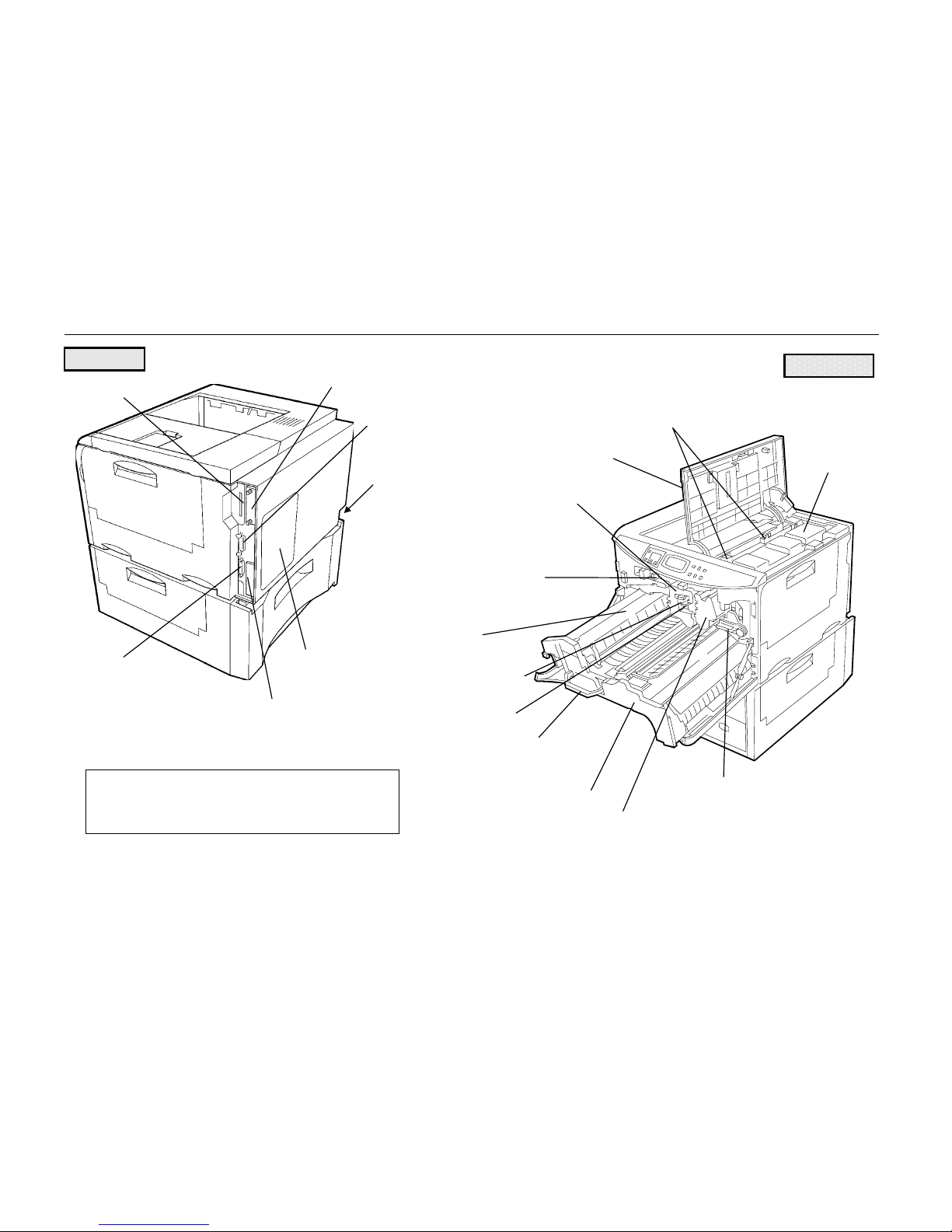
Names of Parts
1- 12
Memory Card Slot
Slot Cover for Optional Hardware
Parallel Interface
Connector*
Serial Interface
(RS-232C/RS-422A)
Connector*
Slot Cover for Installat i on of Optional
Interface
Power Cord
Connector
Rear Panel
Toner Container Release Lever (Green)
Top Cover
Drum Unit
Drum Unit Release Lever (Green)
(Service use only)
Fuser Unit
Charger Unit
Handle for Pulling Out Paper Feed
Unit (Green)
Paper Feed Unit
Developer Unit
Developer Unit Release Lever (Green)
(Service use only)
Toner
Container
*
To prevent static electricity, be sure to cover interface
connectors not being used with the protective caps
supplied with the printer.
Interior View
Cleaning Knob (Green)
Rear View
Page 34

Chapter 1 Safetyguards and Installing the Page Printer
1- 13
Setup and Connections
Set up the printer according to the following steps.
1.
Install the printer on the paper feeder. ............................................................................Page 1-14
2.
Open the top cover. ........................................................................................................Page 1-15
3.
Install the toner container. ..............................................................................................Page 1-16
4.
Close the top cover. ........................................................................................................Page 1-19
5.
Adjust the paper guide on the paper feed cassette. .......................................................Page 1-19
6.
Add paper. ......................................................................................................................Page 1-22
7.
Open the paper stopper on the face-down tray (if required). ..........................................Page 1-24
8.
Open the face-up output tray (when the tray is being used). ..........................................Page 1-24
9.
Connect the printer to the computer. ..............................................................................Page 1-25
10.
Attach the power cord. ....................................................................................................Page 1-27
11.
Test the printer. ...............................................................................................................Page 1-28
12.
Test the interface with the computer. ..............................................................................Page 1-29
13.
Install the printer driver. ..................................................................................................Page 1-30
Page 35
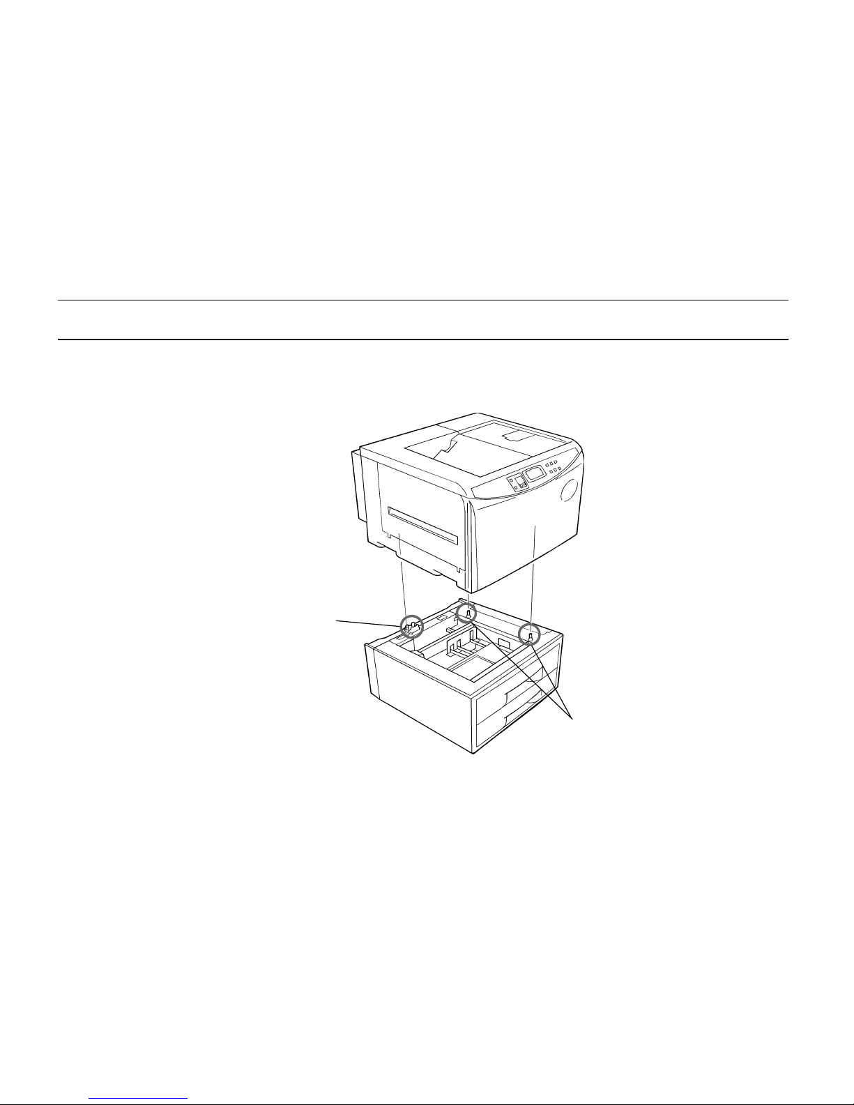
Setup and Connections
1- 14
1. Install the printer on the paper feeder.
Align the installation holes on the bottom of the printer with the positioning pins on top of the paper
feeder and slowly lower the printer into place. Check that the connector on top of the paper feeder is
properly connected to the connector on the bottom of the printer.
Connector
Positioning Pins
Page 36
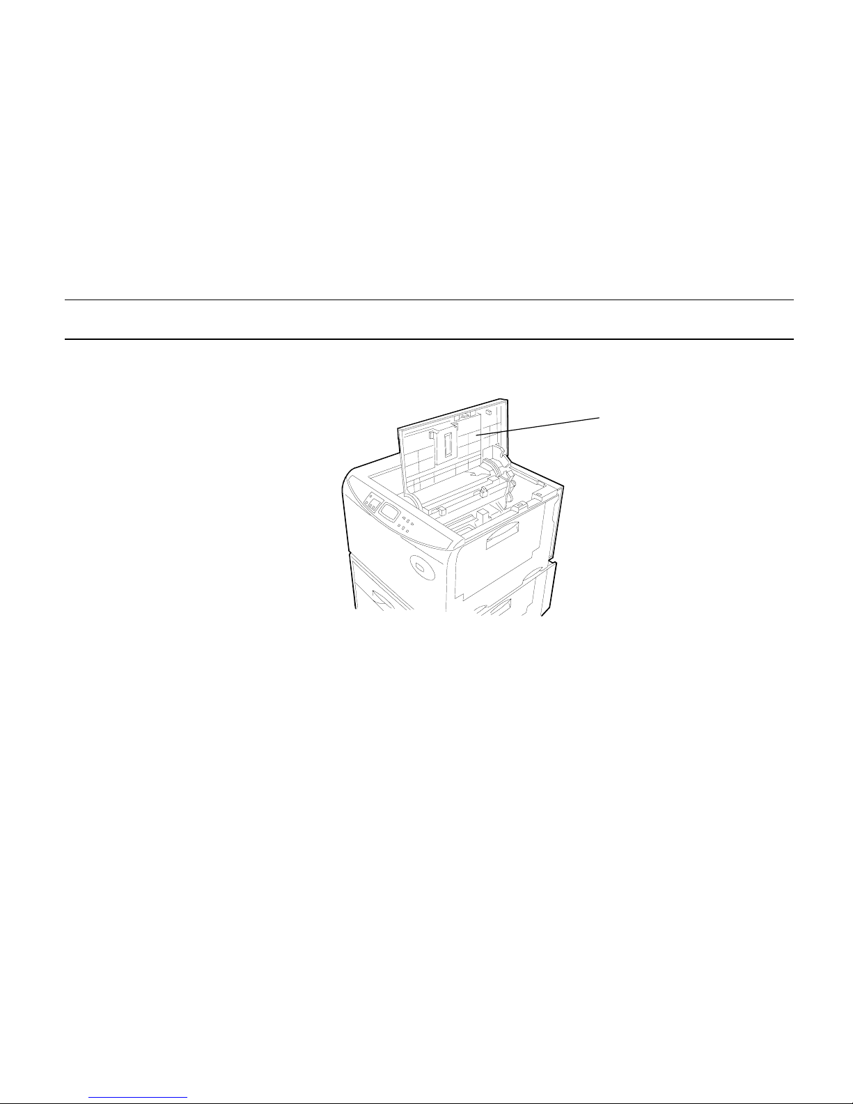
Chapter 1 Safetyguards and Installing the Page Printer
1- 15
2. Open the top cover.
Remove the packing tape stuck to the printer and gently lift the top cover as far as it will go.
Top Cover
Page 37
Setup and Connections
1- 16
3. Install the toner container.
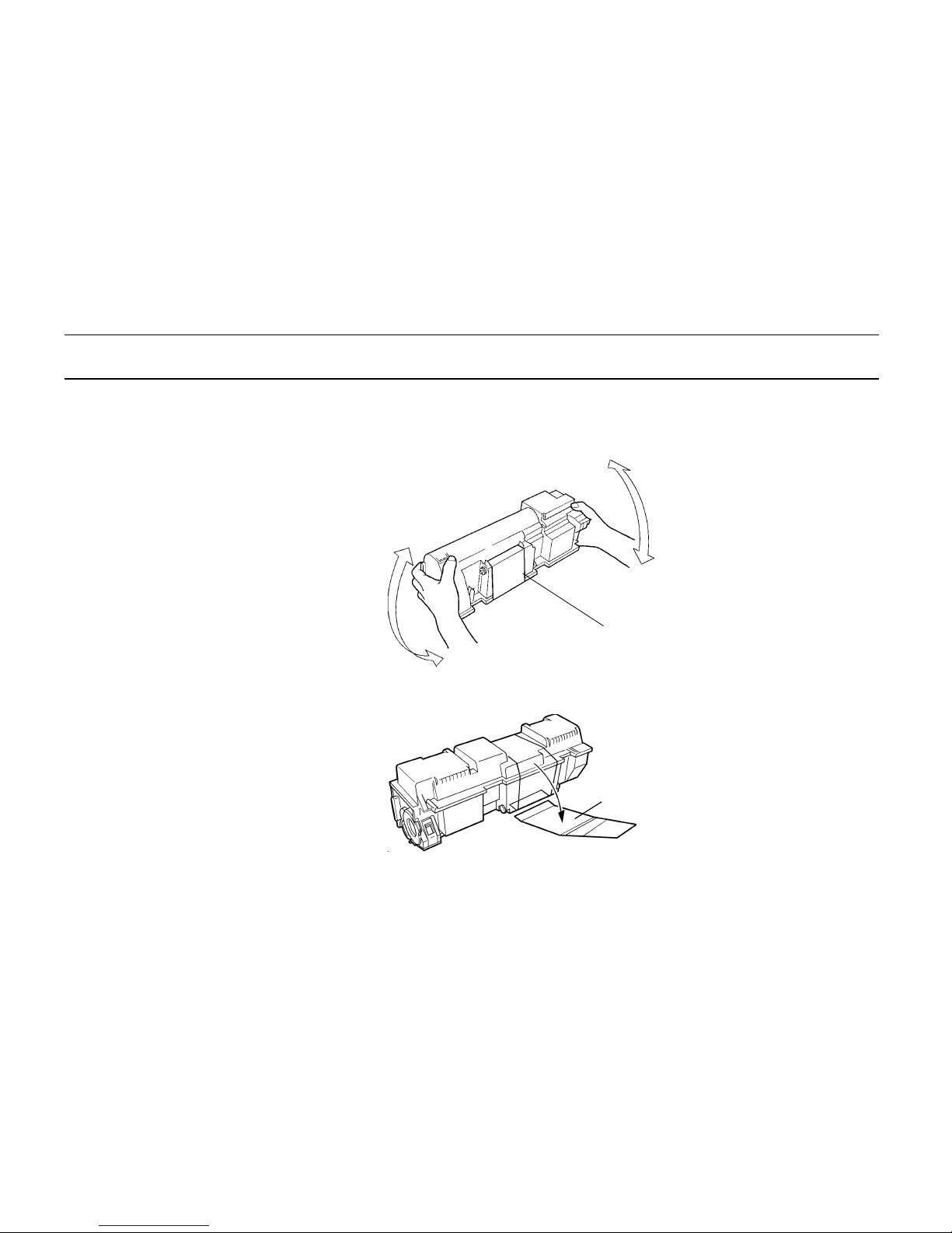
1.
Take the toner container from the toner kit. Shake the toner container with the protective seal
facing up as shown in the figure five times or more to thoroughly mix the toner inside.
2.
Carefully peal off the protective seal.
Shake five or more
times
Protective Seal
Toner Container
Proctective Seal
Page 38
Chapter 1 Safetyguards and Installing the Page Printer
1- 17
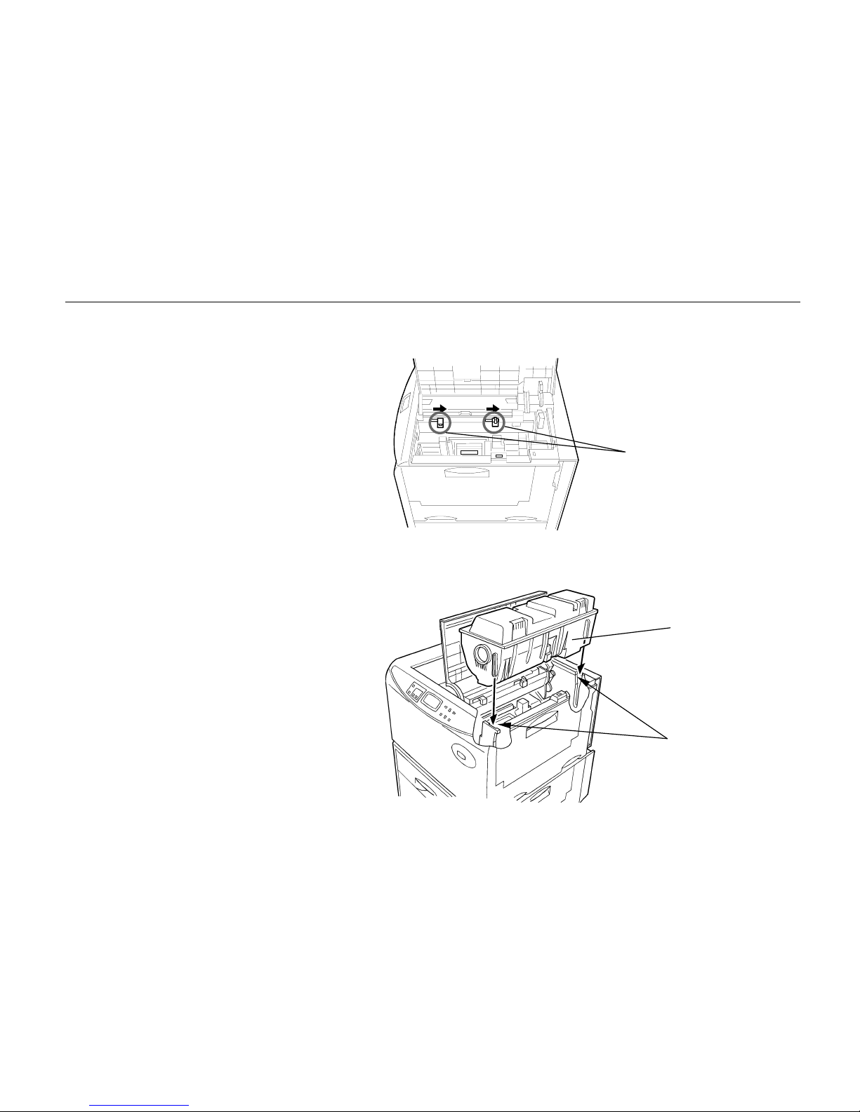
3.
Check that the two toner container release levers are positioned to the right (released) as shown
in the figure. If not positioned to the right, slide them to the right until they stop.
4.
Align the ends of the toner container with the grooves to the left and right inside the printer as
shown in the figure and install.
Toner Container Release Levers
(positioned to right)
Toner Container
Grooves
Page 39
Setup and Connections
1- 18
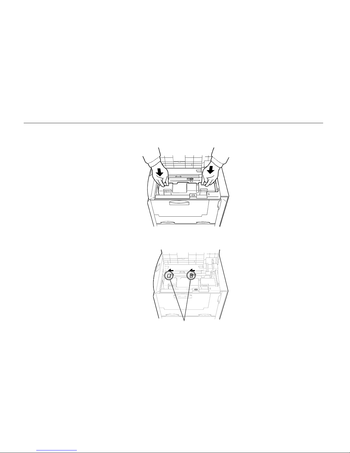
5.
Check that the toner container is installed in the correct position, and push forcefully on the top of
the toner container.
6.
After the toner container is installed, set the two toner container release levers to the left position
(fixed).
Toner Container Release Levers
(Be sure to set to the left and fix the container in place.)
Page 40
Chapter 1 Safetyguards and Installing the Page Printer
1- 19
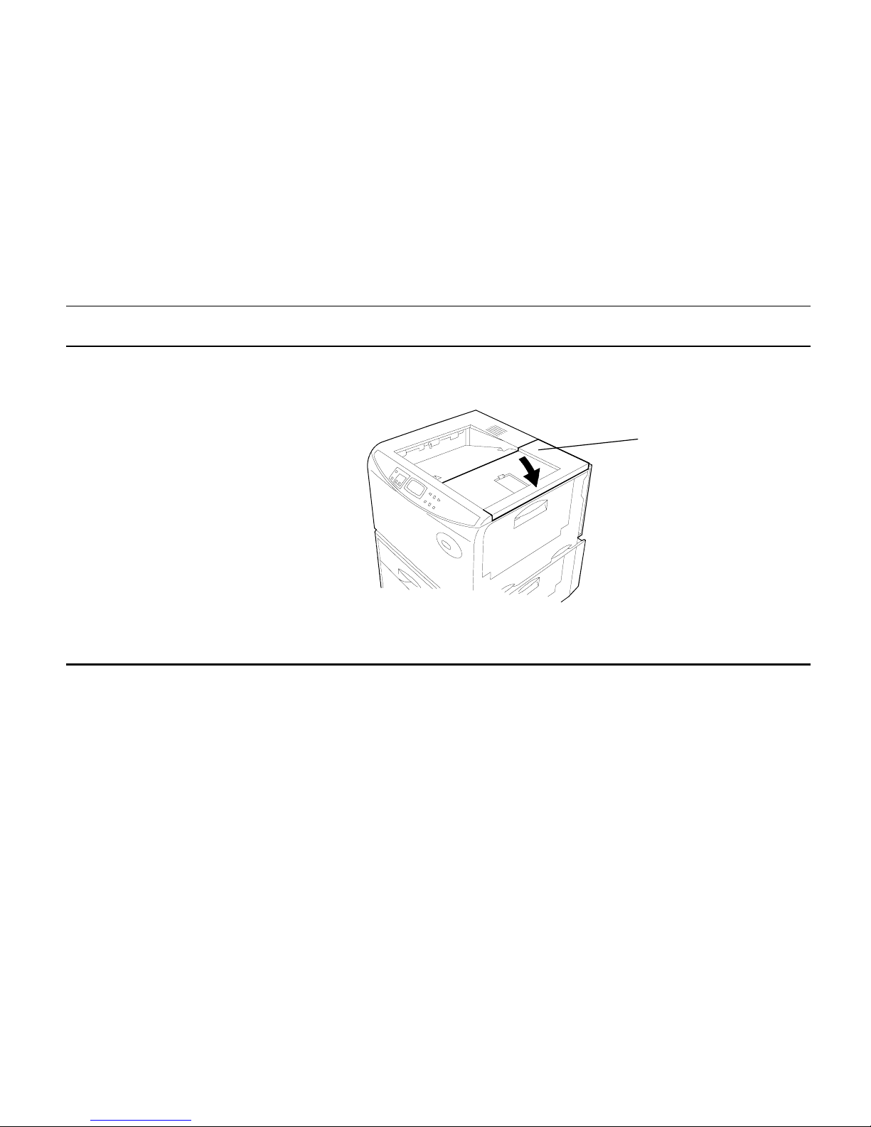
4. Close the top cover.
Close the top cover.
5. Adjust the paper guide on the paper feed cassette.
The paper feed cassette attached to the paper feeder located at the bottom of the printer can be used
to supply standard paper from A5 size up to ledger size by adjusting its paper guide and paper stopper
position. The paper feed cassette is shipped from the factory set to A4 or letter.
The positions for each paper size are indicated inside the paper feed cassette.
Note______________________________________________________________________
A4 and letter size can only be fed in the landscape direction.
Top Cover
Page 41
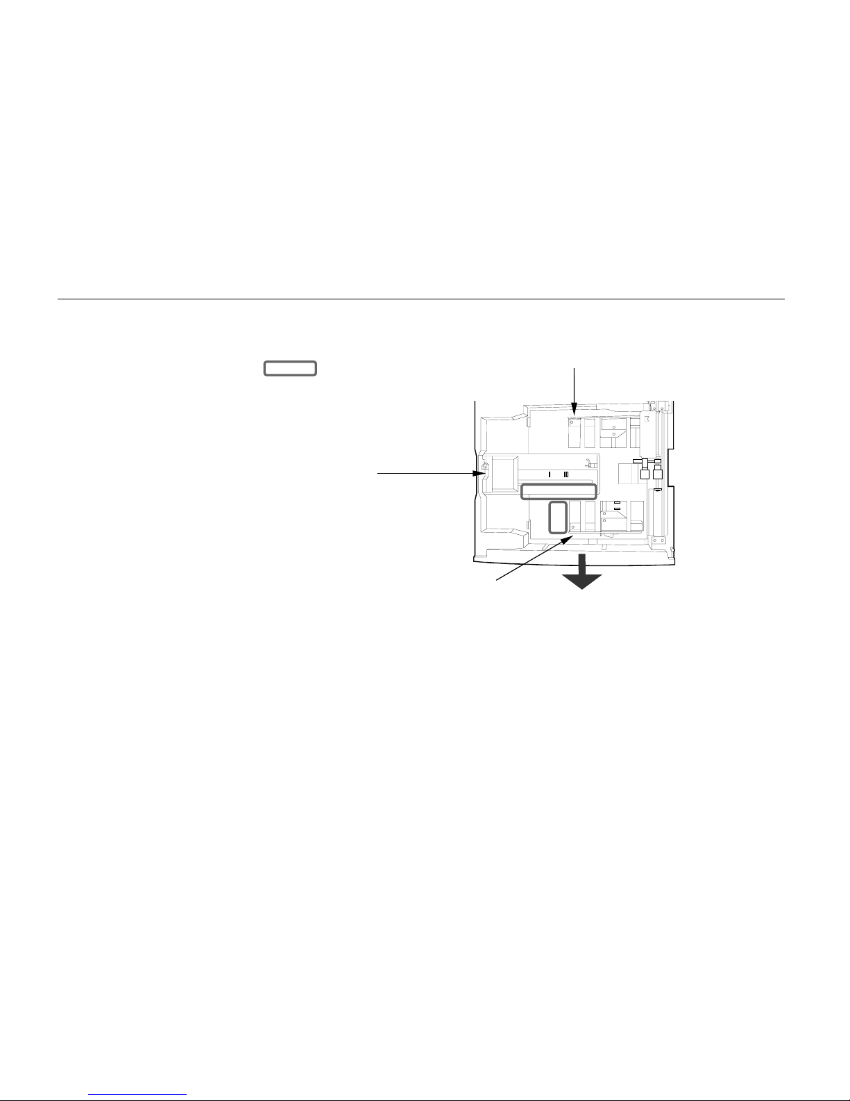
Setup and Connections
1- 20
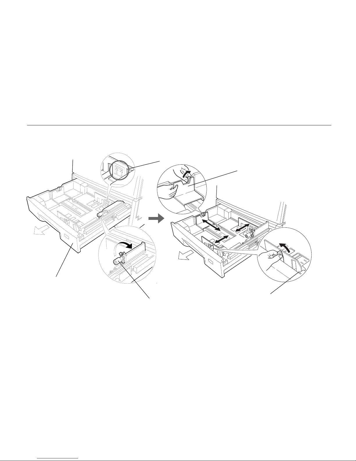
Paper feed cassette position
1.
Pull out the paper feed cassette until it stops.
2.
Open the paper feed roller located on the right side of the cassette until it stops as shown in the
figure.
3.
Next, adjust the position of the paper stopper located on the left side of the cassette. While
holding down the lever (green) on the paper guide, slide the paper stopper to the desired paper
size.
4.
Adjust the position of the paper guides located at the front and rear of the paper feed cassette.
Align the paper guides to the desired paper size by pressing the knobs (green) on the paper
guides so they slide.
: Paper Size Indicator Pos i tion
Paper Stopper
Paper Guide
Front Side
Paper Guide
Page 42
Chapter 1 Safetyguards and Installing the Page Printer
1- 21
Paper Feed Cassette
Paper Limit Indicator
Paper Stopper
Paper Guide
1.
2.
3.
4.
Do not touch the rubber
part of the paper feed
unit.
Page 43
Setup and Connections
1- 22
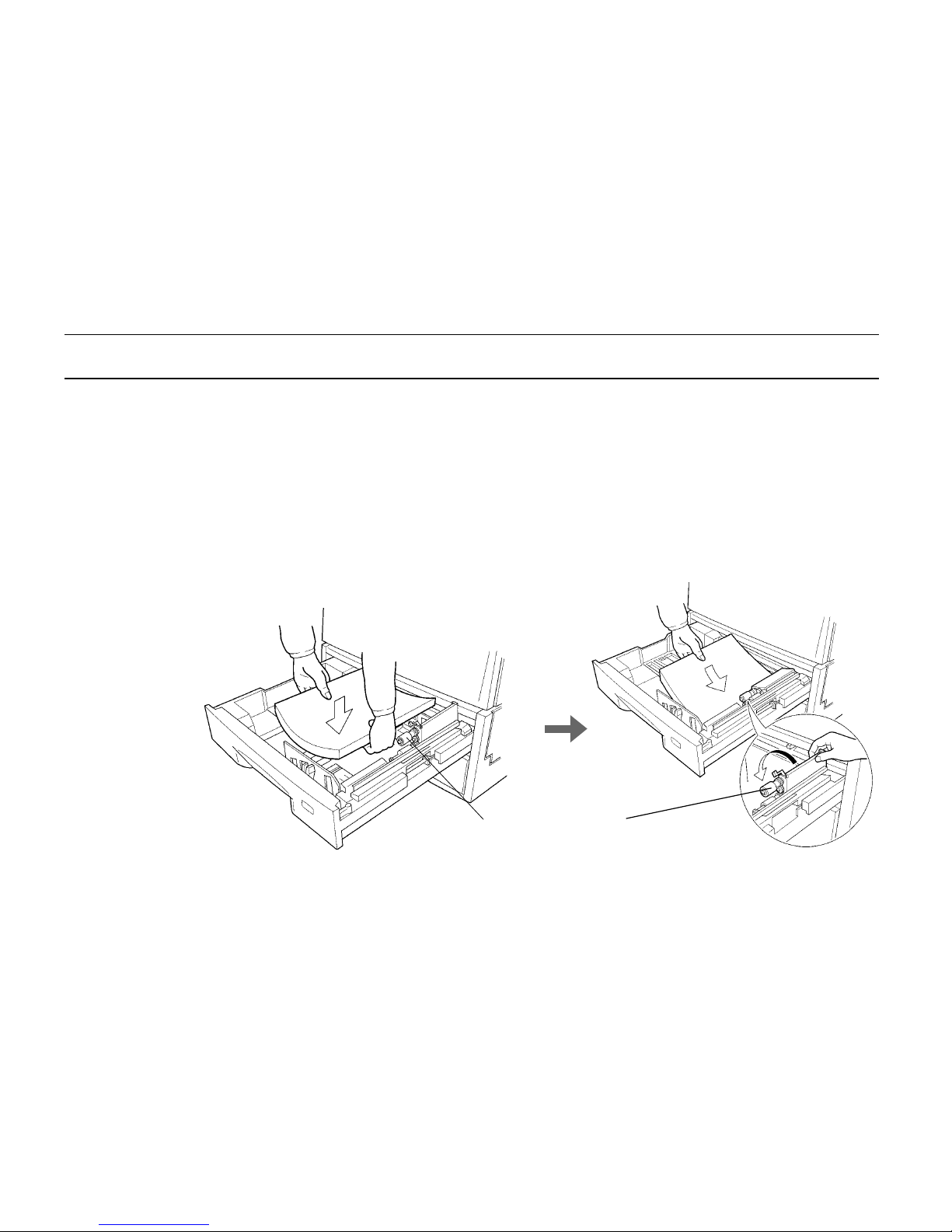
6. Add paper.
Try as much as possible to use fresh paper which has just been opened. Paper which has been
stored long periods contains moisture and may result in sheets sticking together and/or paper jams.
For specifications on the paper which can be used with this printer, please refer to
Appendix B
Paper Selection
.
1.
Square the edges of the paper and insert into the paper feed cassette as shown in the figure.
Be sure that the paper does not exceed the paper limit indicators located on the left and right of
the paper guide (see previous page). The paper feed cassette can hold up to about 500
sheets (0.11 mm thickness per sheet). Printing is performed on the underside of the paper.
2.
Return the opened paper feed roller to its original position.
1.
Do not touch the rubber part
of the paper feed unit.
2.
Page 44
Chapter 1 Safetyguards and Installing the Page Printer
1- 23
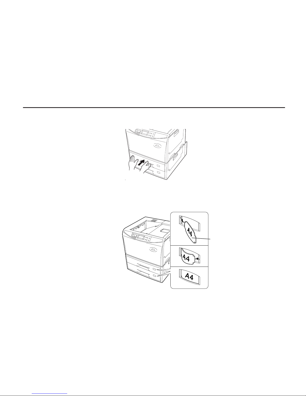
3.
Close the paper feed cassette.
Paper is added to the second paper feed cassette in the same way.
4.
Size indicator plates are also supplied. Place these on the front of the cassette according to
the paper size inside to make it easy to know the current paper size.
Size Indicator
Plate
À
Á
Â
Page 45
Setup and Connections
1- 24
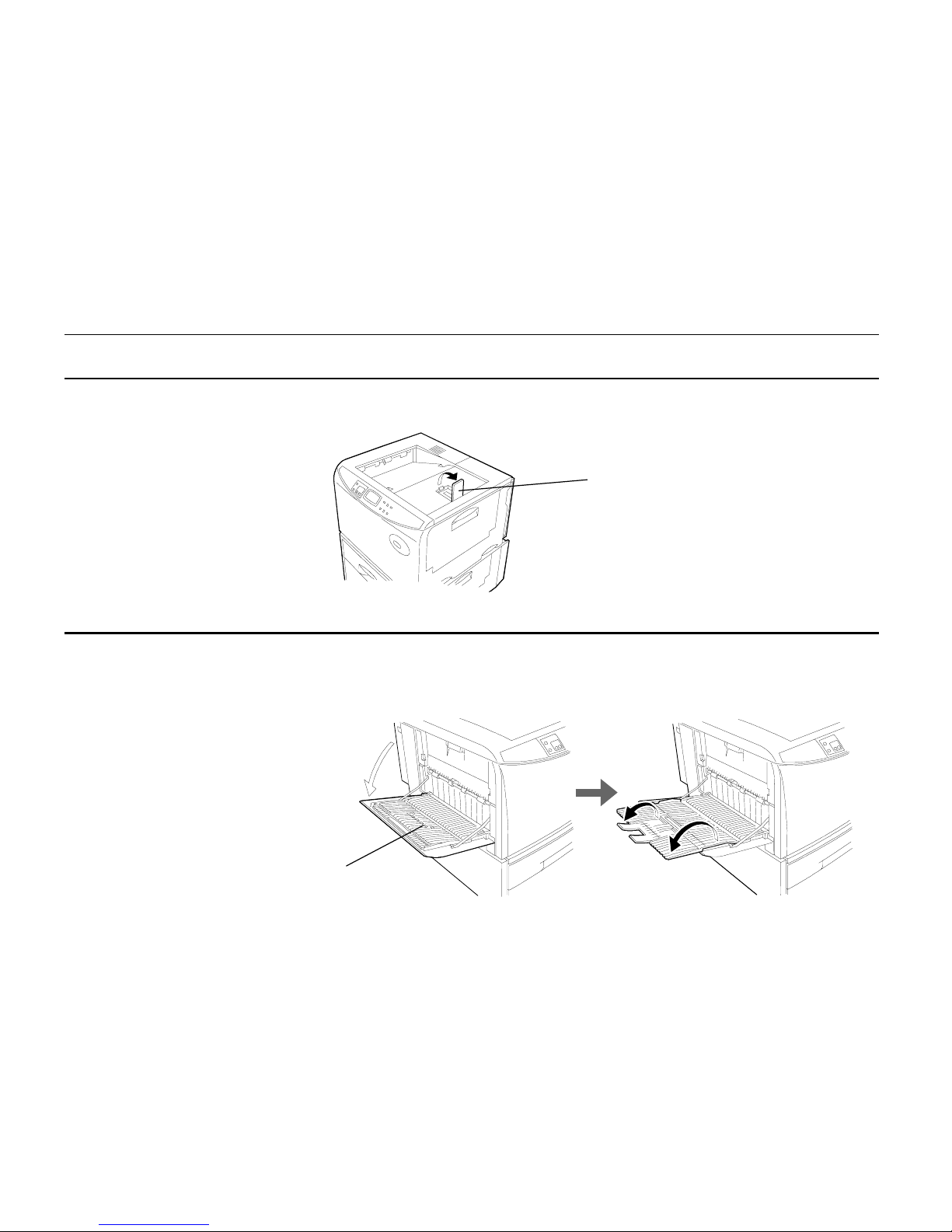
7. Open the paper stopper on the face-down tray (if required).
Raise the paper stopper on the face-down tray.
8. Open the face-up output tray (when the tray is being used).
Use the face-up output tray when you wish paper to be stacked with the printed side facing up
(reverse order). The face-up output tray is located on the left side of the printer. Use it by opening as
shown in the figure.
Paper Stopper
Face-up output tray
Page 46
Chapter 1 Safetyguards and Installing the Page Printer
1- 25
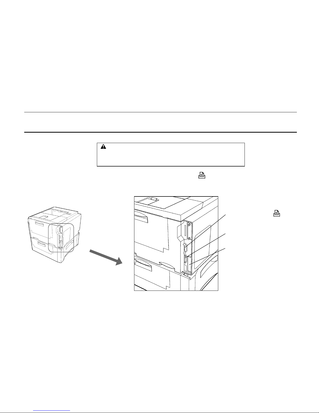
9. Connect the printer to the computer.
A standard Centronics parallel interface connector ( ) and RS-232C/RS-422A serial interface
connector (
IOIOI
) are located on the rear side of the printer. For pin connections, please refer to
Appendix C
.
Parallel Interface Connector (
)
Serial Interface (RS-232C/RS-422A) Connector
(
IOIOI
)
Slot Cover for Installat i on of Optional
Interface
CAUTION
Before performing this step, be sure to turn off the printer's power switch and
unplug the power plug from the power outlet. Failure to do so may result in
electric shock.
Page 47
Setup and Connections
1- 26
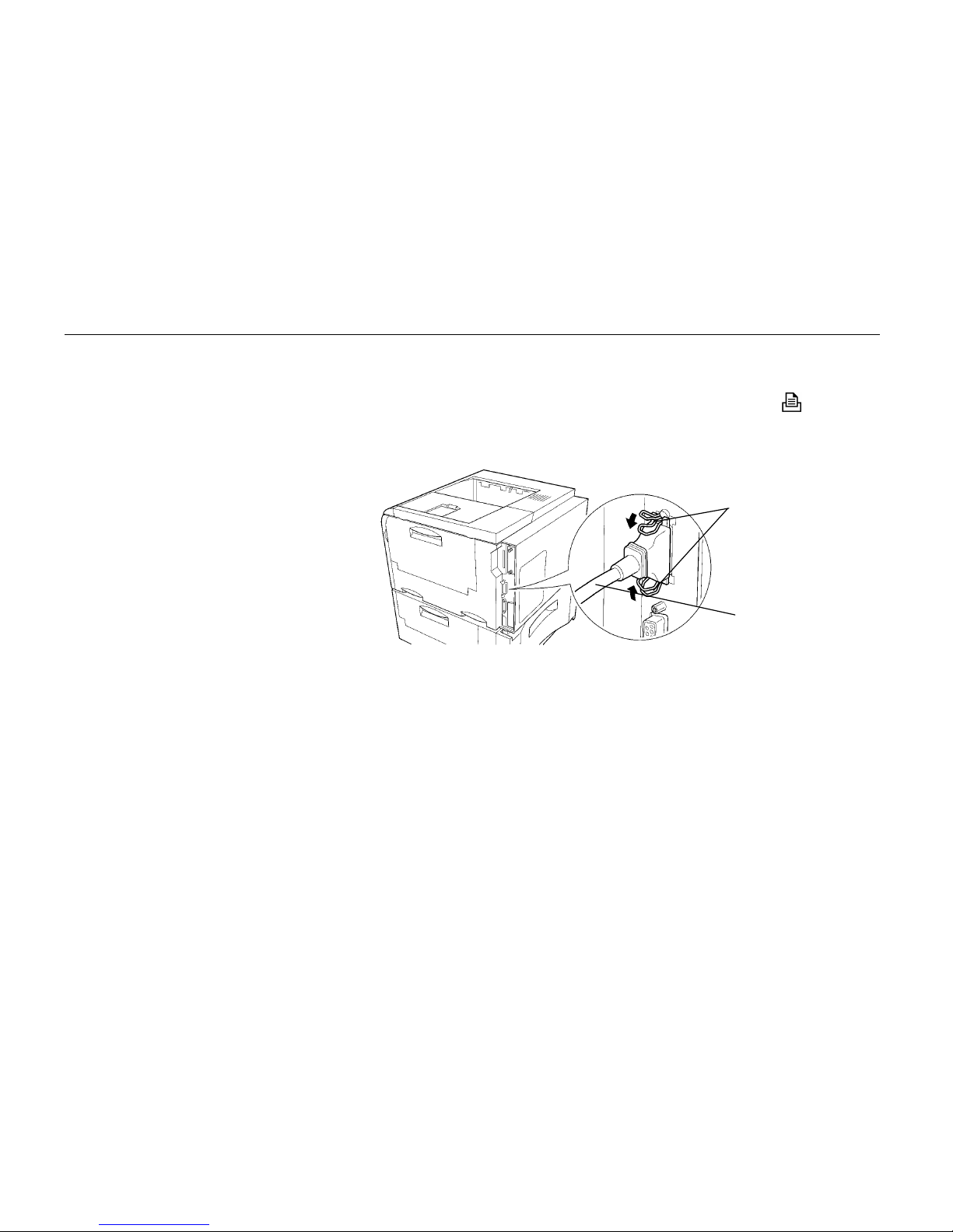
Parallel Interface Connection
1.
Plug one end of the printer cable into the connector on the printer marked with a
(parallel)
symbol.
2.
Close the clips on both sides to fix the connector in place.
3.
Plug the other end of the printer cable into the computer’s parallel (Centronics) interface
connector. This connector is usually labled PRINTER. For details, please refer to the hardware
manual for the computer.
Serial Interface Connection
The printer is shipped from the factory with its serial interface set to RS-232C mode, but it can also be
set to RS-422A mode in accordance with how it will be used. For details, please refer to
Appendix C
.
1.
Plug one end of the cable into the connector marked
IOIOI
on the printer.
2.
Tighten the screws on both sides securely.
3.
Plug the other end of the cable into the computer's serial interface connector. For details,
please refer to the hardware manual for the computer.
Clips
Printer Cable
Page 48
Chapter 1 Safetyguards and Installing the Page Printer
1- 27
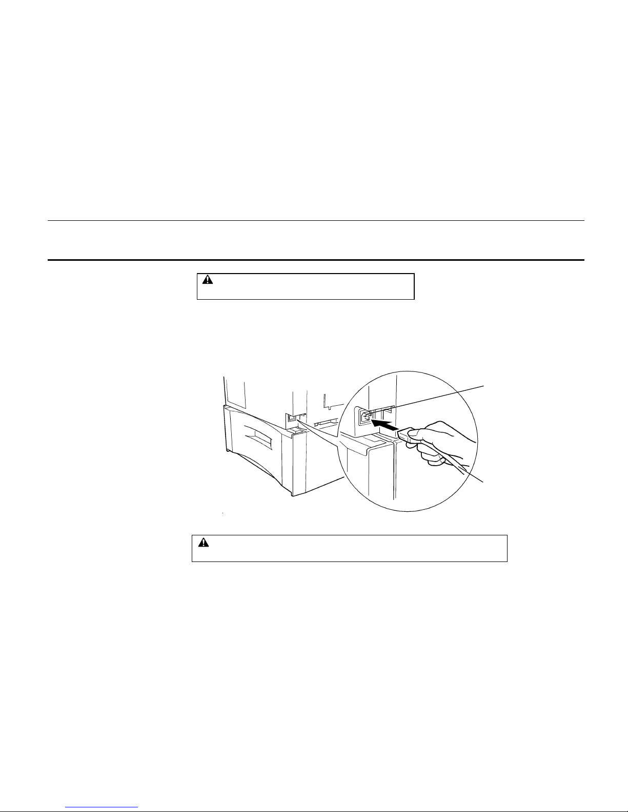
10. Attach the power cord.
Note______________________________________________________________________
Only use the power cord supplied with the printer.
1.
Plug the power cord into the power cord connector on the rear side of the printer.
2.
Connect the other end of the power cord into a power outlet.
Power Cord
Power Cord Connector
CAUTION
Be sure the printer's power switch is turned off.
WARNING
Be sure to connect the ground wire of the printer to ground.
Page 49

Setup and Connections
1- 28
11. Test the printer.
Use the following procedure to test the printer and print out a status page indicating factory settings.
For details on the indicators and keys on the printer’s control panel, please refer to
Chapter 2
Control Panel
.
1.
Turn on the printer's power switch.
It does not matter whether the computer's power is on or off. Self test will be displayed in
the message display of the printer.
Notes_____________________________________________________________________
·
When the printer’s power is turned on after a toner container has been installed for the first time,
the printer will display the message
Please wait
for about five minutes until it becomes ready for
printing (Ready). Note that the printer is not broken.
·
An error message of the form XXX
Open
will be displayed in the printer’s message display unless all
covers on the printer are properly closed. If this happens, check that the part indicated in the error
message is properly closed.
2.
Wait until the ON LINE indicator lights and Ready appears in the message display.
If the ON LINE indicator is off, make it light by pressing the
ON LINE
key.
3.
Press the
STATUS
key. Information such as the margin position and memory allocation
currently set for the printer will be printed on a page in a list.
If the status page prints without problems, you can tell that the developer unit and paper feed cassette
are installed properly. For details on the contents of the status page, see
Chapter 2
.
Page 50

Chapter 1 Safetyguards and Installing the Page Printer
1- 29
12. Test the interface with the computer.
In order to check that the printer and the computer are properly connected you must print by sending
an actual command from the computer.
1.
Turn on the printer's power switch and turn on the computer’s power as well.
2.
Wait until the message display switches from Self test to Ready.
3.
Check that the ON LINE indicator is lit. If it is not lit, make it light by pressing the
ON LINE
key.
4.
Enter and execute the following command at the DOS prompt on the computer screen.
ECHO !R! STAT; EXIT;> PRN
If this causes the printer to print a status page (a page on which current printer settings are printed),
then the printer and computer are properly connected. If this does not print a status page, check that
the printer cable is properly connected. The cable or one of the connectors may also be broken.
Notes on Application Software
The computer and printer have been successfully connected by the procedures up to this point. In
order to print from software run on the computer, it is necessary to install a printer driver on the
computer to which the printer is connected. After the printer driver is installed, be sure to make proper
printer settings from within the software.
Page 51
Setup and Connections
1- 30
13. Install the printer driver.
A CD-ROM containing a printer driver for Windows (Windows 3.1, Windows 95 and Windows NT
3.51/4.0) is supplied with this printer. Once this printer driver is installed on the computer, it is
possible to make various settings for this printer from within Windows applications. It is also possible
to control options and printing from within Windows.
For each of these operating systems, the printer driver is located in the folder on the CD-ROM. The
steps for installing this driver are given below. Read this in conjunction with the manual supplied with
Windows.
For details on how to install the printer driver under Windows NT, read the file README.TXT in the
CD-ROM's root directory.
Installing Under Windows 95
1.
Insert the supplied CD-ROM into the CD-ROM drive of the computer.
2.
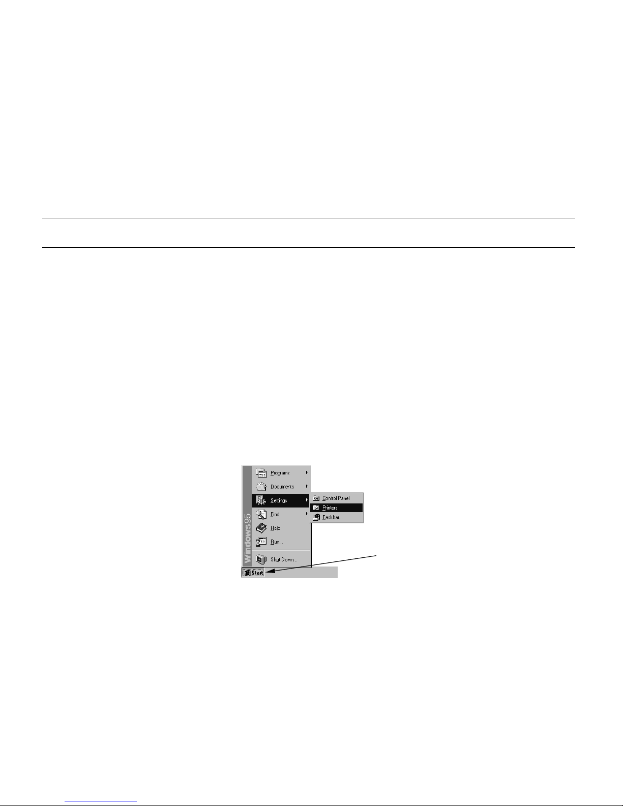
Click on
“
Start" with the mouse on the Windows95 Task Bar, and align the cursor with “Setting.”
Click on
“
Printers” among the items displayed.
Start Button
Page 52
Chapter 1 Safetyguards and Installing the Page Printer
1- 31
3.
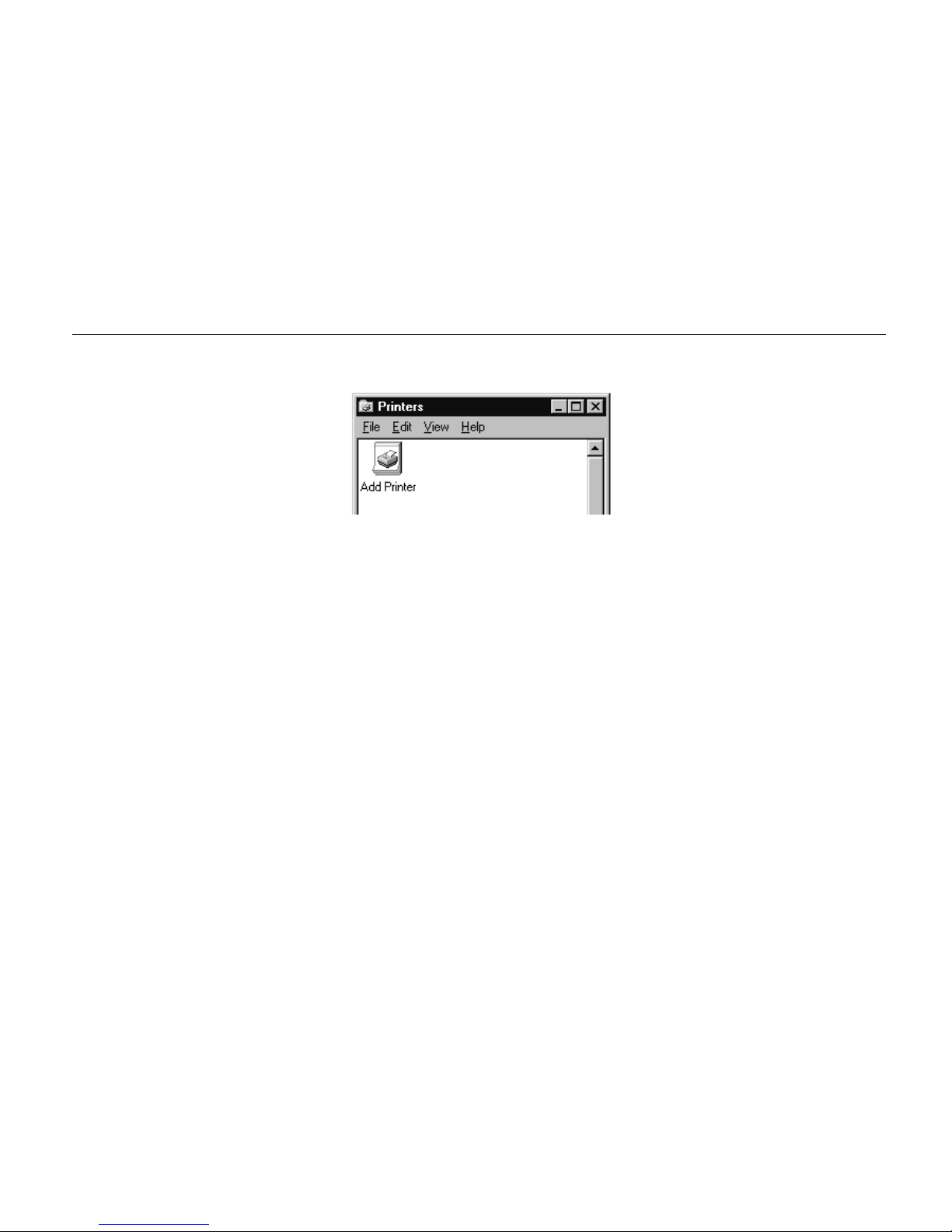
The printer folder will open. Double click on
“
Add printer.”
4.
The Printer Wizard screen will appear. Click on
“
Next >.”
5
. A screen for selecting the printer to be connected will appear. Select the most appropriate
printer and click on
“
Next.”
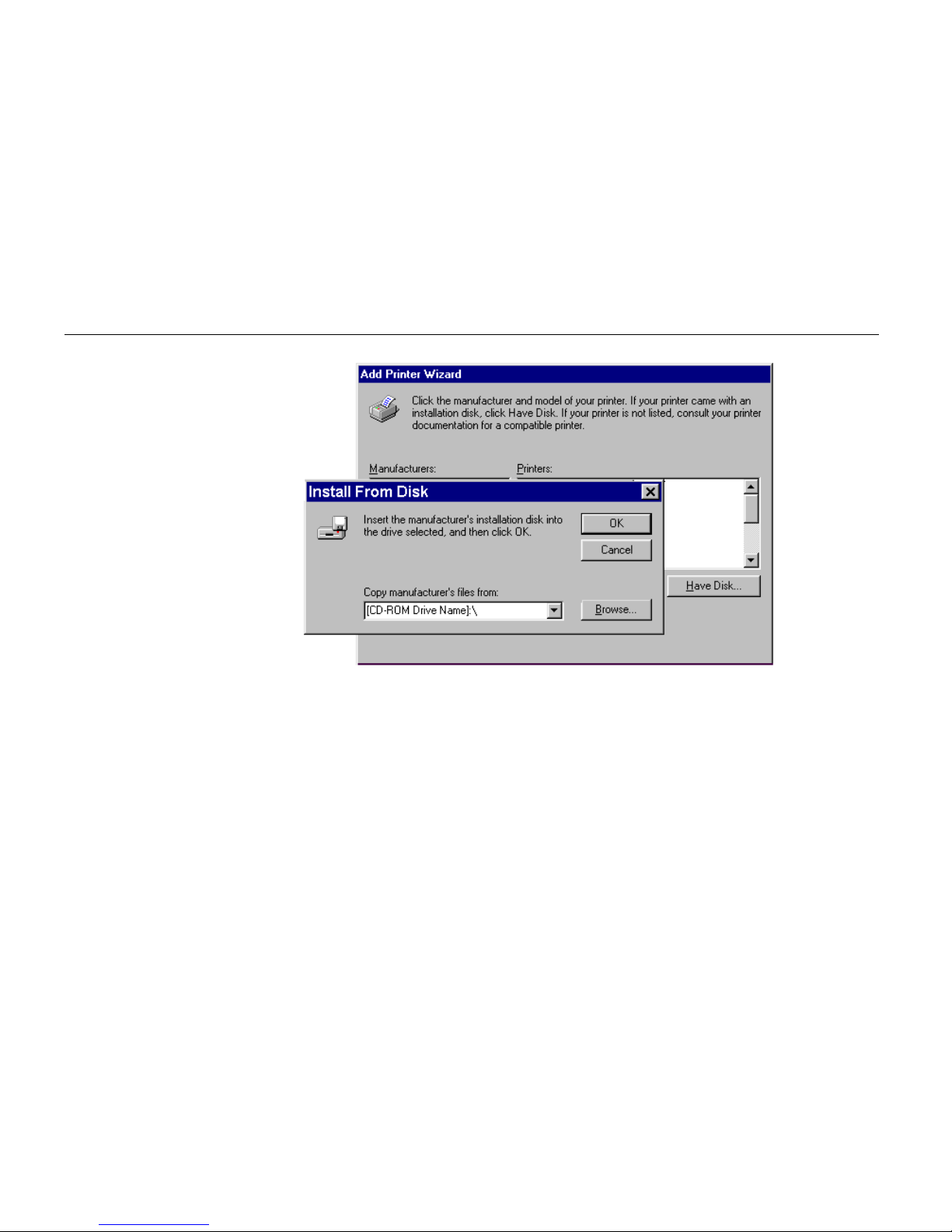
6.
Next,
“
Click the manufacturer and model of your printer....” screen will appear. At this point,
select
“
Have Disk…” located at the lower right. (See the figure for
Step 7
.)
7.
A screen for installing from floppy disk will appear. Enter
“
[CD-ROM Drive Name]:\” as the
source from which to copy the file and click on
“
OK.
”
Page 53
Setup and Connections
1- 32
8.
Select
“
DP-2800,” click on “Next >,” and follow the on-screen instructions to install. Once the
driver has been properly installed, the printer icon will be added to the printers folder.
Note______________________________________________________________________
When printing under Windows 95, be sure to set the emulation of this printer to HP LaserJet 5Si
(default setting).
Page 54
Chapter 1 Safetyguards and Installing the Page Printer
1- 33
Installing Under Windows 3.1
1.
Insert the supplied CD-ROM into the CD-ROM drive of the computer.
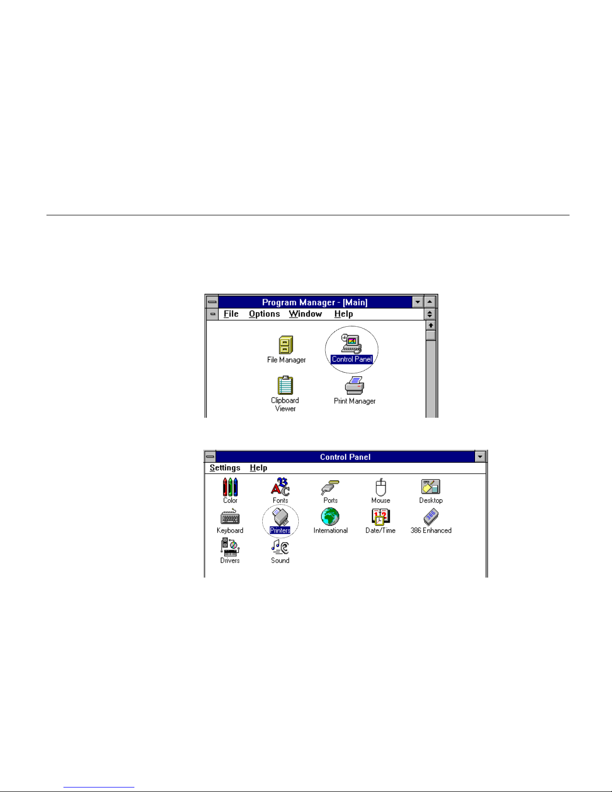
2.
Double click on the Control Panel.
3.
Double click on “Printers.”
Page 55
Setup and Connections
1- 34
4.
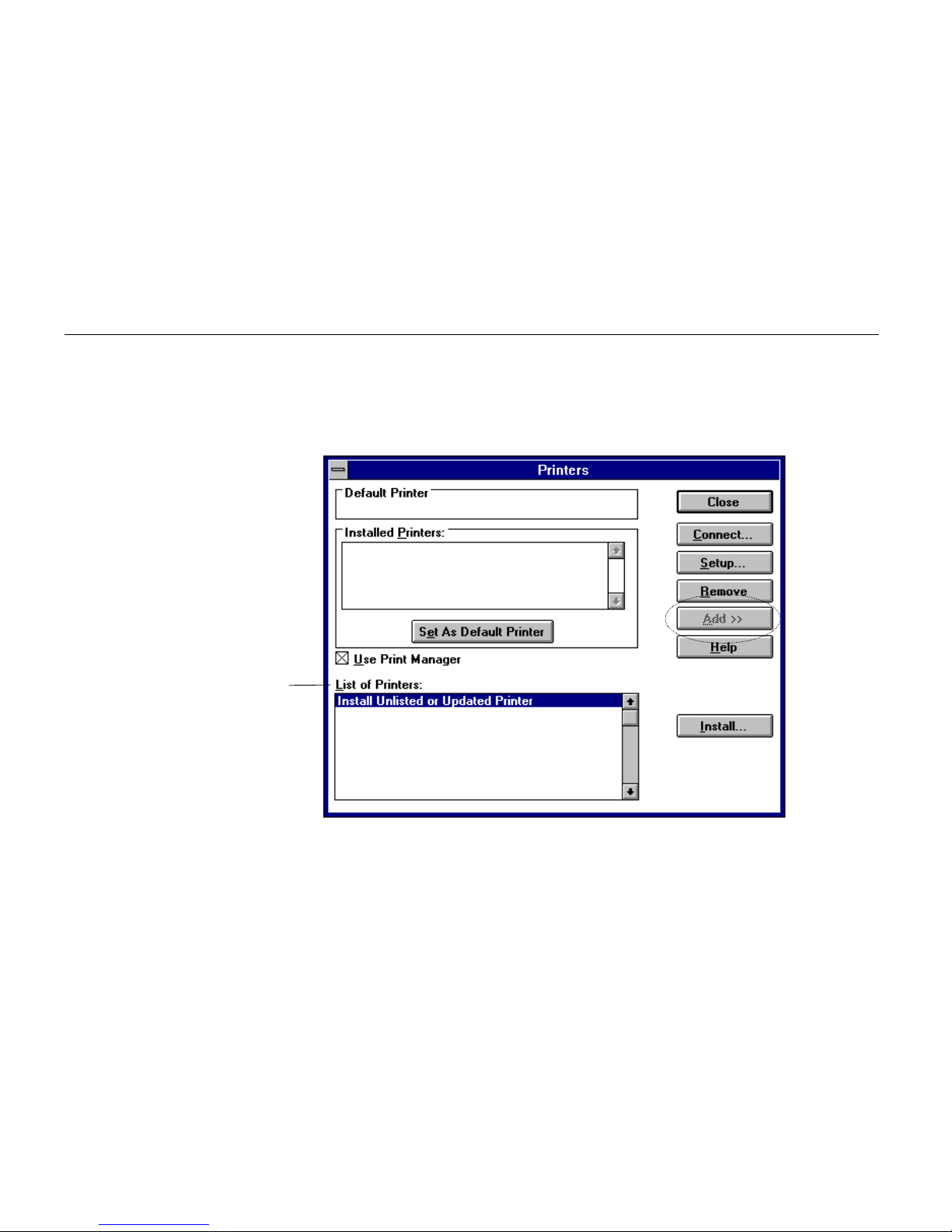
Click on
“
Add >>.”
5.
A screen for
“
List of Printers:” will appear. From the choices, click on “Install Unlisted or
Updated Printer.”
4.
5.
Page 56
Chapter 1 Safetyguards and Installing the Page Printer
1- 35
6.
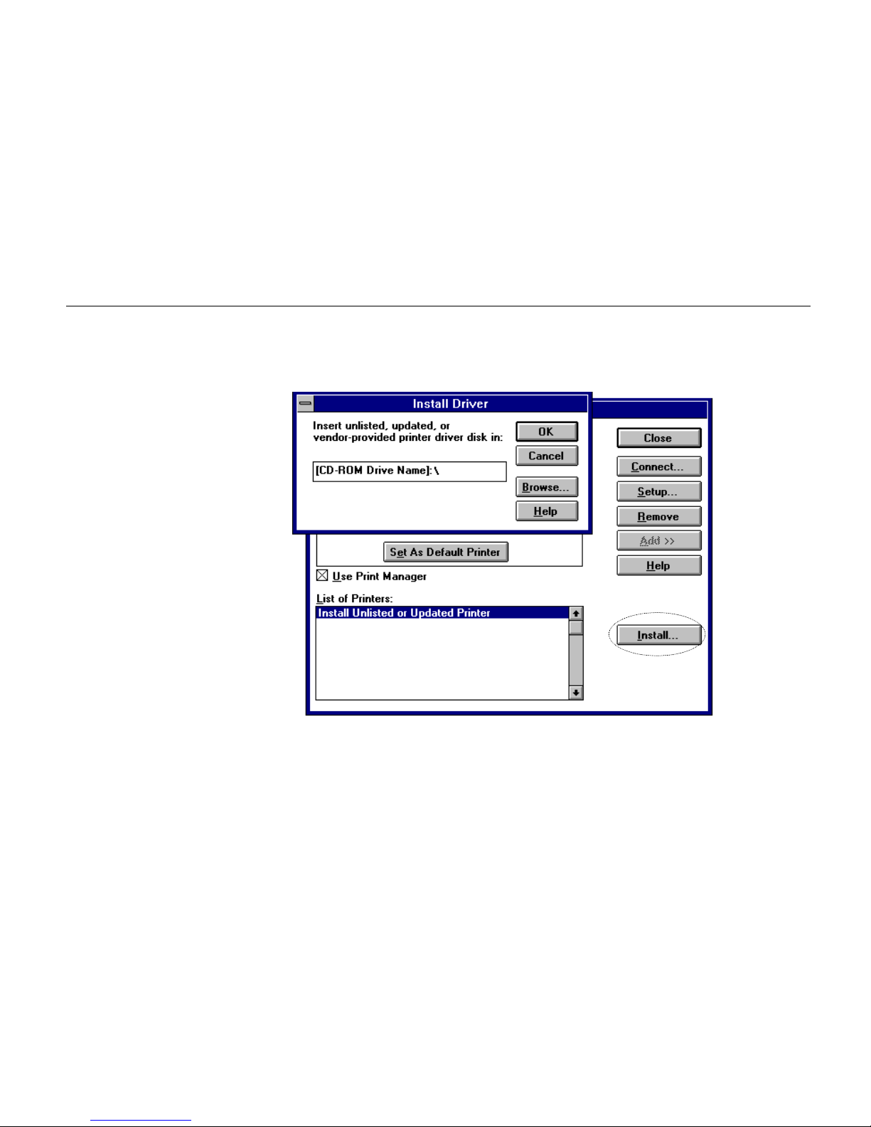
Click on
“
Install….”
7.
The install printer menu will appear. Enter
“
[CD-ROM Drive Name]: \” and click on “OK.”
8.
Select “DP-2800” from the printers displayed and click on “OK.” Once the driver has been
installed, close the Control Panel by clicking on “Close.”
6.
Page 57

The Multi-Purpose Tray
1- 36
The Multi-Purpose Tray
The multi-purpose tray is incorporated on the right side of the printer. It can be used in one of three
modes: first mode, cassette mode or manual mode. The multi-purpose tray can hold about 100
sheets of paper (0.11 mm thickness).
First Mode (Automatic Manual Feeding)
The printer automatically feeds any paper placed on the multi-purpose tray even if another paper
source is selected. After all paper in the multi-purpose tray is printed, paper will be fed from the paper
source originally set. (This is the factory set default.)
Cassette Mode
Approximately 100 sheets of paper can be continuously fed.
Manual Mode
Special non-standard paper can be fed one sheet at a time.
For details on paper which can be used with this printer, please refer to
Appendix B
.
In first mode and manual mode, printing is carried out using custom size paper feed timing regardless
of the size setting for multi-purpose tray.
Page 58
Chapter 1 Safetyguards and Installing the Page Printer
1- 37
Feeding from the Multi-Purpose Tray
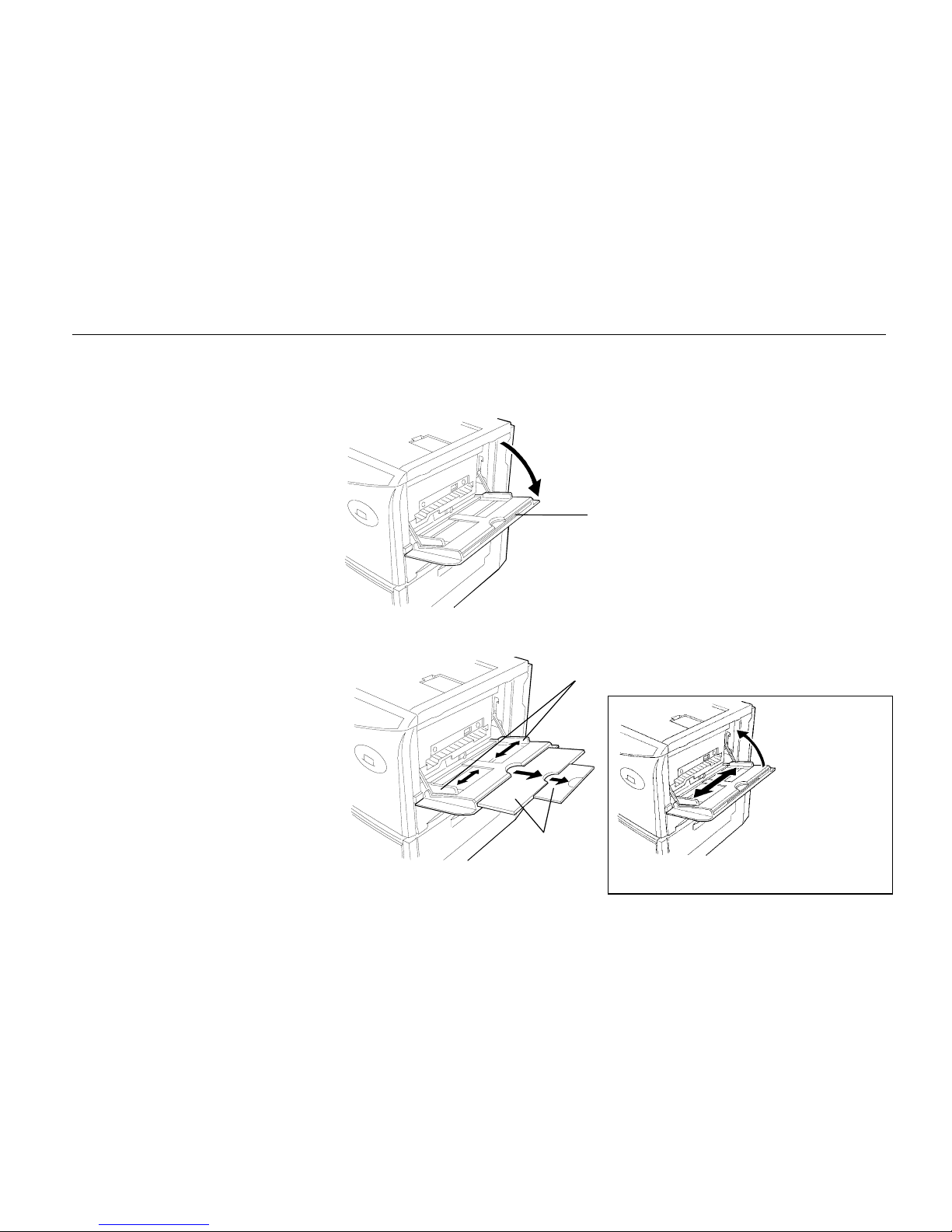
1.
Open the multi-purpose tray as shown in the figure.
2.
Open the sub tray and adjust the paper guides according to the width of the paper to be fed.
Multi-purpose tray
Paper guides
Sub tray
Note:
The paper guides must be set to the narrowest
position when closing the mult i -purpos e tray.
Page 59

The Multi-Purpose Tray
1- 38
3.
Check that the message Ready is displayed in the printer's message display, and that the ON
LINE indicator is lit.
4.
Set the paper source to the multi-purpose tray by pressing the
FEED
key until the message
display indicates MP tray. The multi-purpose tray indicator on the control panel will flash, and
Add paper will be displayed.
5.
Press the
MODE
key to display MP tray mode >.
6.
Press the
4 (
Form Feed
) key to display >MP tray size, then press the
ENTER
key so
you can set the paper size to be fed from the multi-purpose tray. See
Mode Select Menu
at
the end of this HANDBOOK.
The manner in which paper is fed in each of these modes is explained below.
First mode
1.
Press the
MODE
key to display MP tray mode >.
2.
After pressing the
ENTER
key, the mode display is changed by pressing the + and – keys.
Display First and then press the
ENTER
key.
MP tray mode >
First
3.
Press the
EXIT
key.
Note______________________________________________________________________
In this mode, the paper source indicator on the control panel does not change while paper is being fed
from the multi-purpose tray.
Page 60
Chapter 1 Safetyguards and Installing the Page Printer
1- 39
Cassette Mode
1.
Press the
MODE
key to display MP tray mode >.
2.
After pressing the
ENTER
key, the mode display is changed by pressing the + and – keys.
Display
Cassette
and then press the
ENTER
key.
MP tray mode >
Cassette
3.
Press the
EXIT
key.
4.
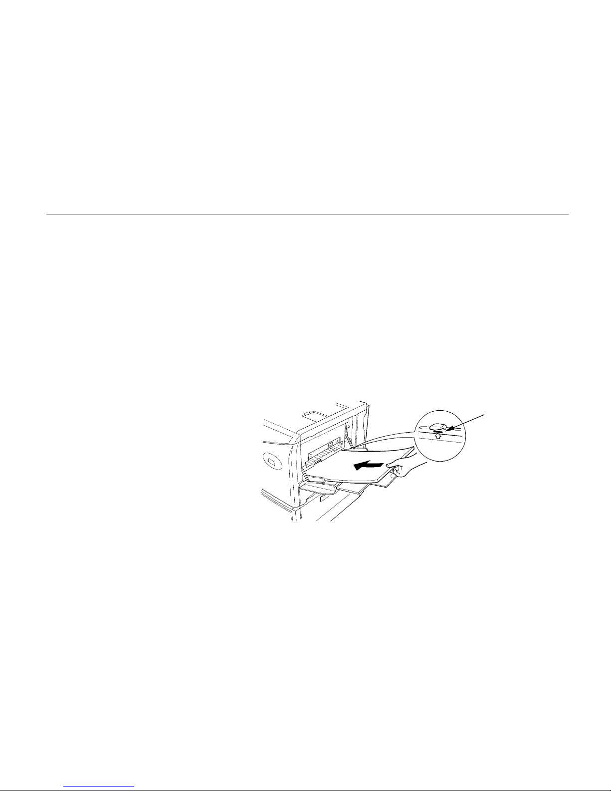
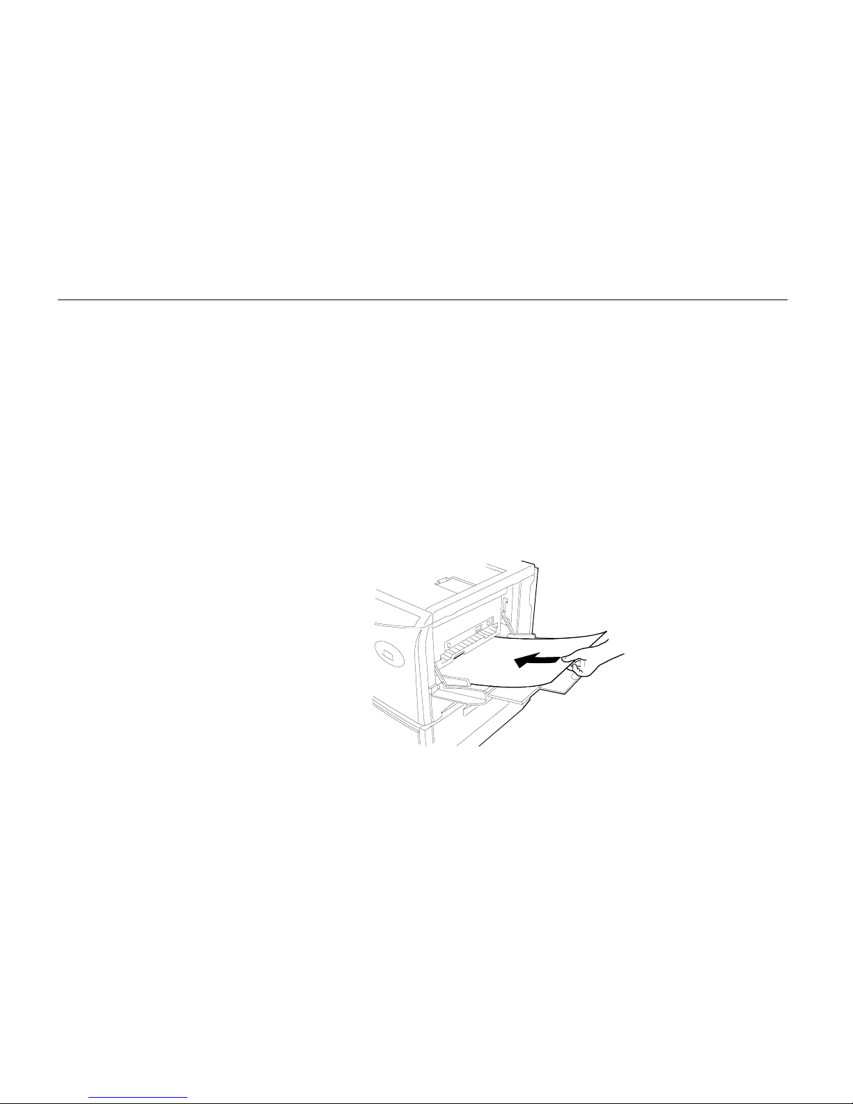
Insert the paper so that it is aligned straight in the tray as far as it will go. About 100 sheets
(0.11 mm thickness, 80 g/m
2
) can be inserted at one time. Do not load paper above the paper
limit mark.
5.
Ready will appear on the message display.
Paper limit mark
Page 61
The Multi-Purpose Tray
1- 40
Manual mode
1.
Press the
MODE
key to display MP tray mode >.
2.
After pressing the
ENTER
key, the mode display is changed by pressing the + and – keys.
Display
Manual
and then press the
ENTER
key.
MP tray mode >
Manual
3.
Press the
EXIT
key.
4.
Insert the paper in the multi-purpose tray as far as it will go. About 100 sheets (0.11 mm
thickness, 80 g/m
2
) can be inserted at once. Do not load paper above the paper limit mark
(See page 1-38).
5.
Ready will appear on the message display.
6.
Send printing commands and data from the computer.
Page 62
Chapter 1 Safetyguards and Installing the Page Printer
1- 41
7.
The message display will display Processing after which the message Set paper Press
CONTINUE will be displayed.
If you want to abandon the manual feeding procedure, press the
CANCEL
key. The message
display will indicate Print Cancel? Current job. Press the
ENTER
key. Printing
will stop and the printer will return to “ Ready ”.
8.
If you wish to continue printing, press the
CONTINUE
key. Paper loaded in the tray will be fed
and printed. To continue printing in manual mode, repeat the steps from
step 4
.
Feeding Envelopes
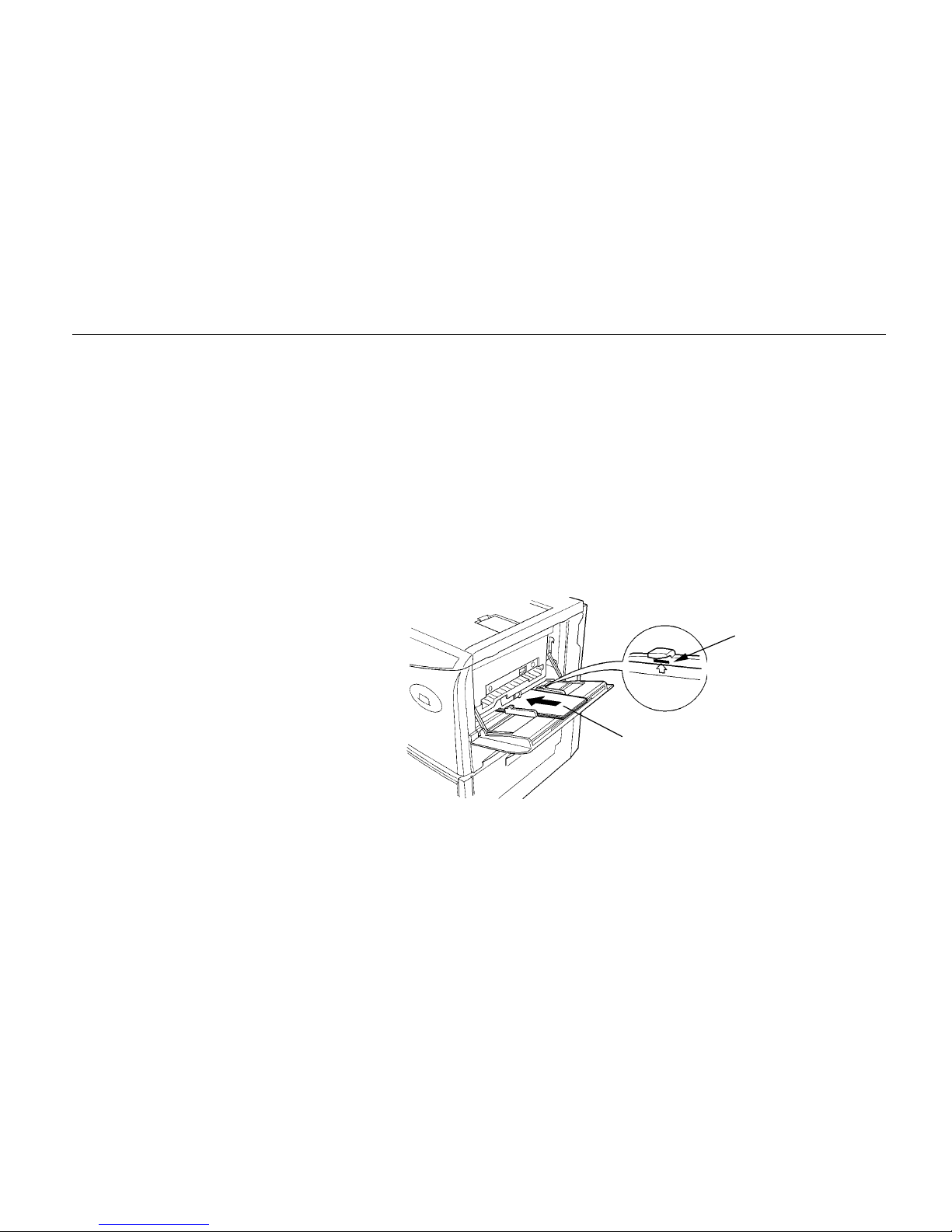
Envelopes should be fed face up. Be sure to set the print direction from the Mode Select Menu. Insert
the envelopes in the tray as far as they will go. Do not load envelopes above the paper limit mark.
For details on suitable envelope paper quality and shape, see
Appendix B
. Be sure to use suitable
envelopes as print quality may be reduced.
For the envelope sizes which can be used with this printer, see the table on page 2-5.
Envelopes
Paper limit mark
Page 63

Expanding Memory
1- 42
Expanding Memory
The printer comes standard equipped with 4 MB of main memory. However, more complex pages can
be printed and processing speed increased by expanding the printer's memory. There are two slots
available in the printer for expanding memory. Printer memory can be expanded to up to 68 MB by
installing optional extended memory chips (SIMMs) in these slots.
Note______________________________________________________________________
The expansion memory should be installed only by an authorized dealer or a certified technician. We
shall not be liable for damage due to improper installation of the expansion memory.
Memory Required by the Printer Environment
It may be necessary to extend memory depending on the operating environment of the printer. Please
refer to the table below for minimum memory requirements in various environments.
Minimum Memory Required
Resolution: 300 dpi Resolution: 600 dpi
HP LaserJet 5Si (factory setting) 4 MB 4 MB
HP LaserJet 5Si, duplex mode = on* 4 MB 6 MB
HP LaserJet 5Si, duplex mode = off
Resource protection
— 10 MB
HP LaserJet 5Si, duplex mode = off
Resource protection
— 14 MB
*An optional duplex unit (AD-31) is required for duplex printing.
Printing Environment
Page 64
Chapter 1 Safetyguards and Installing the Page Printer
1- 43
The description given below is intended for service personnel.
Precautions on the Handling of Extended SIMMs
Static electricity which may accumulate in the human body through walking on carpets or other such
surfaces is the enemy of SIMMs loaded with many semiconductor chips. Pay attention to the following
things before installation to protect memory chips against damage from static electricity.
·
Do not remove the SIMMs from their anti-static bag until immediately prior to installation.
·
Eliminate any static electricity from your body through grounding before touching the SIMMs.
·
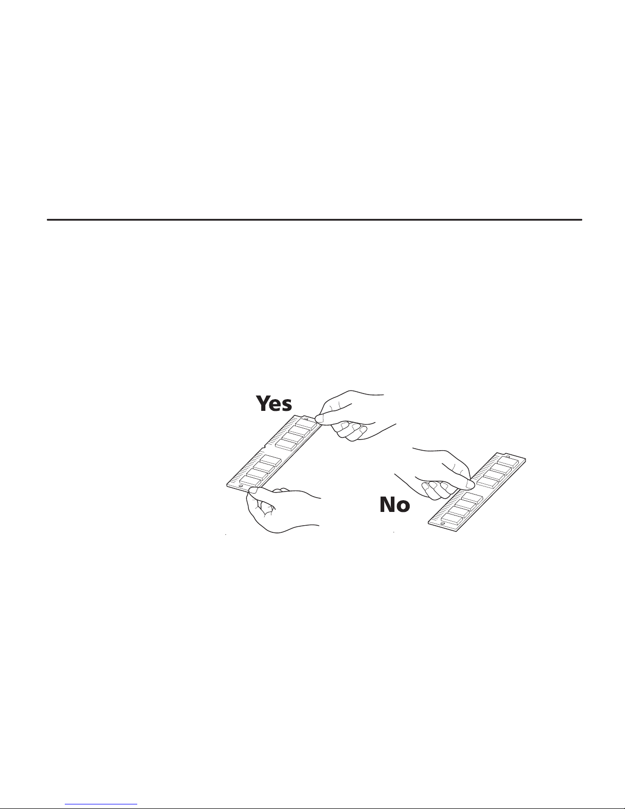
Be absolutely sure when handling the SIMMs to hold them by the substrate without touching the
printed connector section.
Page 65
Expanding Memory
1- 44
Installing SIMMs
Insert the SIMM or SIMMs into the dedicated sockets on the printer's main board.
WARNING
Take precautions that no foreign substances such as metal chips or liquid get inside the
printer during the installation process. Operation of the printer during the presence of a
foreign substance may lead to fire or electric shock.
WARNING
Be sure to turn off the printer's power and disconnect all cables when installing SIMMs in
the printer. Failure to do so may lead to electric shock.
Page 66
Chapter 1 Safetyguards and Installing the Page Printer
1- 45
1.
Turn off the printer's power and disconnect the power cord and all cables connected to the
printer.
2.
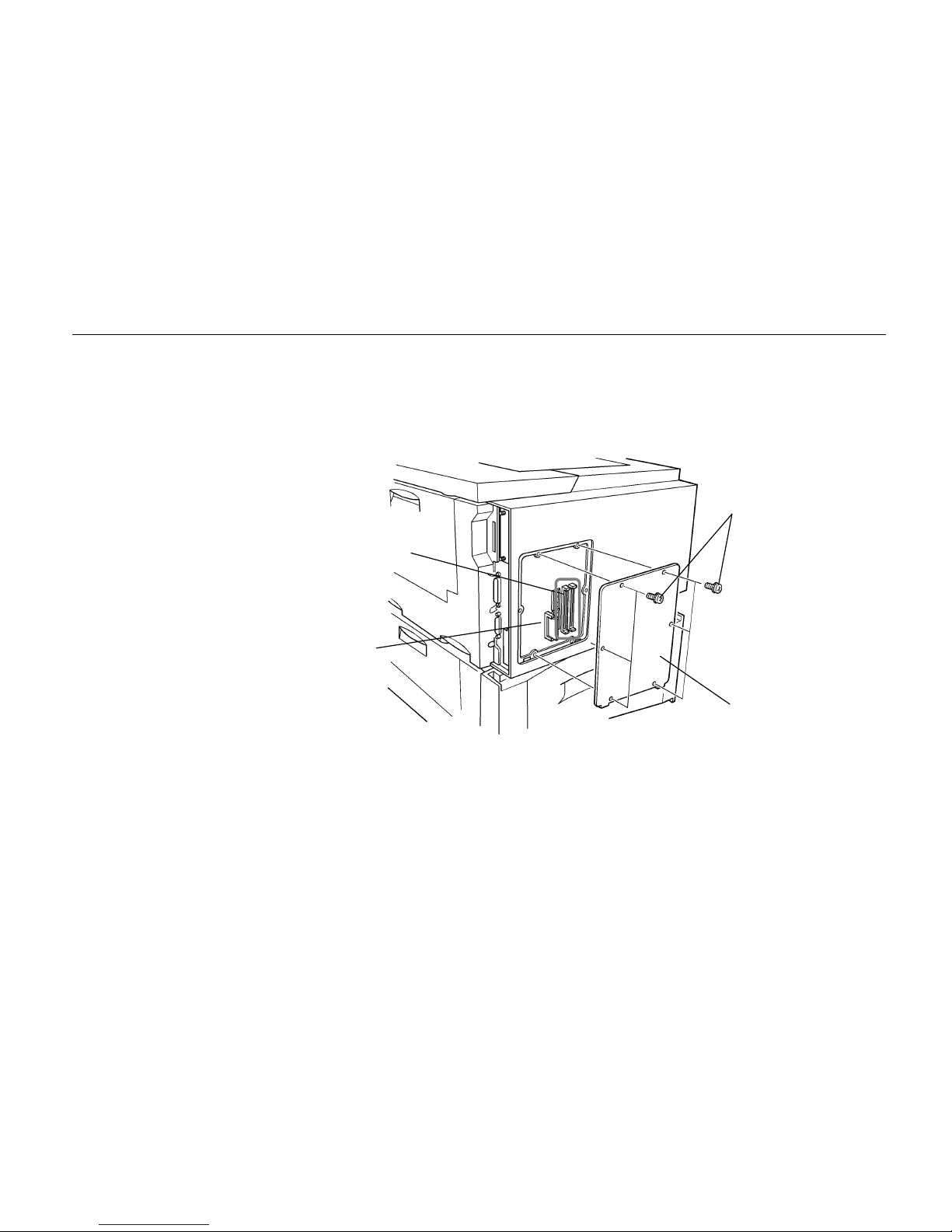
Remove the six screws on the printer's rear cover, and remove the rear panel. There are two
sockets for installing SIMMs located on the main board.
Sockets for Installing
SIMMs
Screws
Rear Panel
Main Board
Page 67
Expanding Memory
1- 46
3.
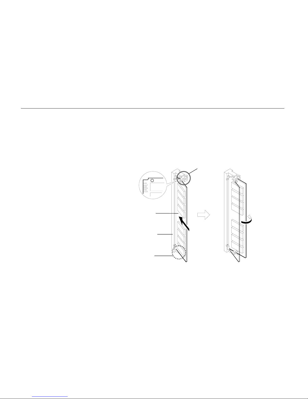
Remove the SIMM or SIMMs from the package.
À
Align the connector side of the SIMM with the socket groove paying attention to the left
and right sides of the SIMM.
Á
Gently push both sides of the top edge of the SIMM into the groove and gently push it
upright. Check that both edges of the SIMM are being held in place by the catches on
the socket.
Note______________________________________________________________________
SIMMs may be installed in either slot regardless of their memory capacity.
Catch
SIMM
Socket
Catch
À
Á
Page 68
Chapter 1 Safetyguards and Installing the Page Printer
1- 47
4.
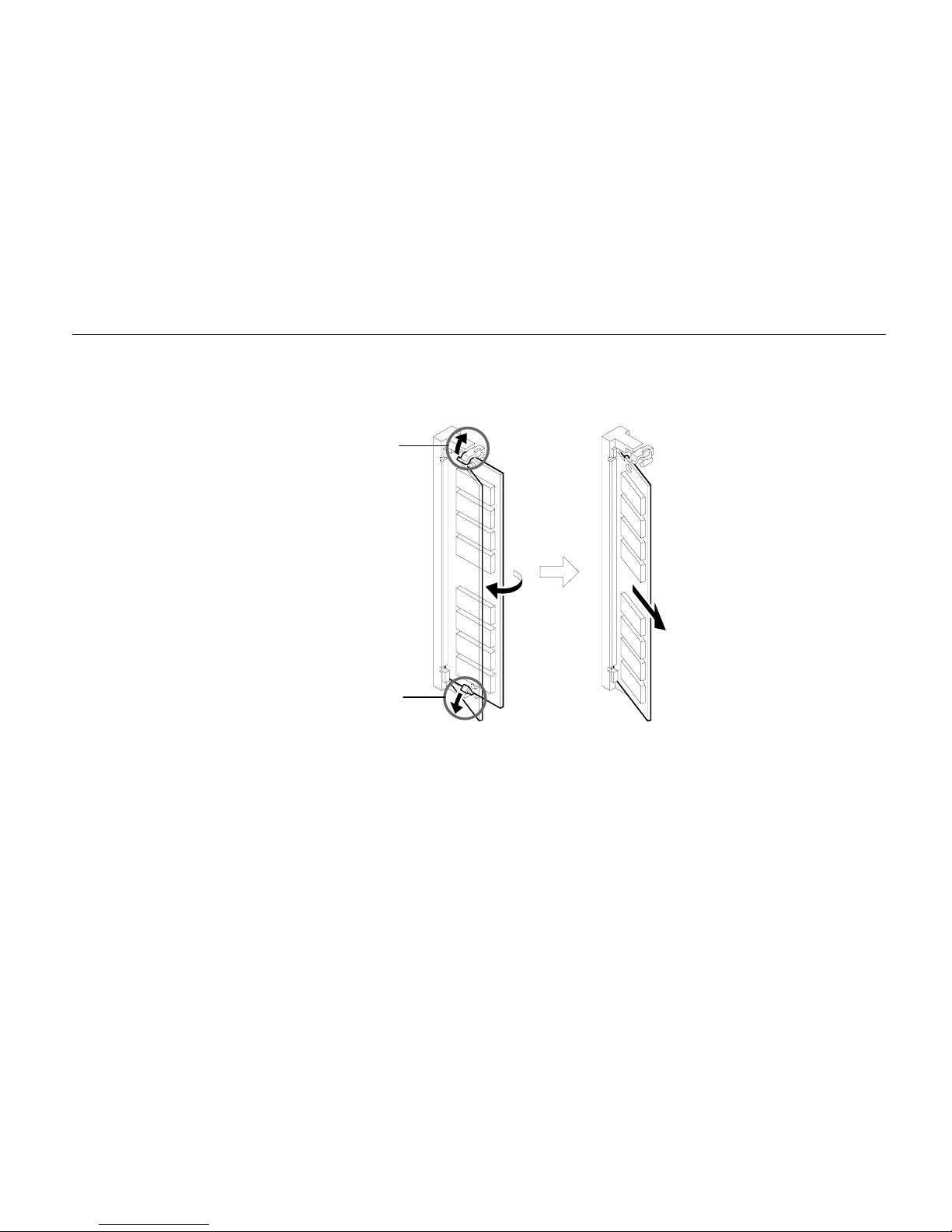
To remove a SIMM from a socket, open the catches on both sides of the socket as shown in the
figure. Remove the SIMM from the socket.
5.
After the SIMMs have been installed, reattach the rear cover on the printer and tighten all six
screws securely.
After SIMMs have been installed in the printer, use the following procedure to check that installation
has been performed properly.
Catch
Catch
Page 69

Expanding Memory
1- 48
Testing Extended Memory
1.
Check that the power switch is off, plug the power cord into the printer, and turn the power on.
2.
Wait for the printer's
ON LINE
indicator to light and the message display to read Ready, and
press the
STATUS
key.
3.
If installation has been performed properly, a status page will be printed. Check the
Available
Memory Item
in the upper right. Information on the SIMMs installed in slot 1 and slot 2 is
shown here. There is no problem if total memory has increased. (The printer is shipped from
the factory with 4096 KB [4 MB] of memory.)
Page 70

Chapter 2 Operating the Page Printer
2-1
Chapter 2
Operating the Page
Printer
This chapter explains the printer's control panel and operating
procedures. It also covers operations which use the memory
cards.
Control panel ......................................................................2- 2
Operating Procedures.........................................................2-11
Mode Selection Menu......................................................... 2- 24
Configuring Interfaces.........................................................2-27
Emulation Selection............................................................2- 28
Reduction (Page Set) .........................................................2- 29
Memory Cards....................................................................2-32
Sleep Timer Setting............................................................2-43
Dumping Received Data.....................................................2- 44
KIR Level............................................................................2-45
Ecoprint Mode.....................................................................2-47
Resource Protection...........................................................2-48
Adjusting the Print Density..................................................2-49
Setting the Audio Warning (Buzzer) ...................................2- 49
Page 71
Control Panel
2-2
Control Panel
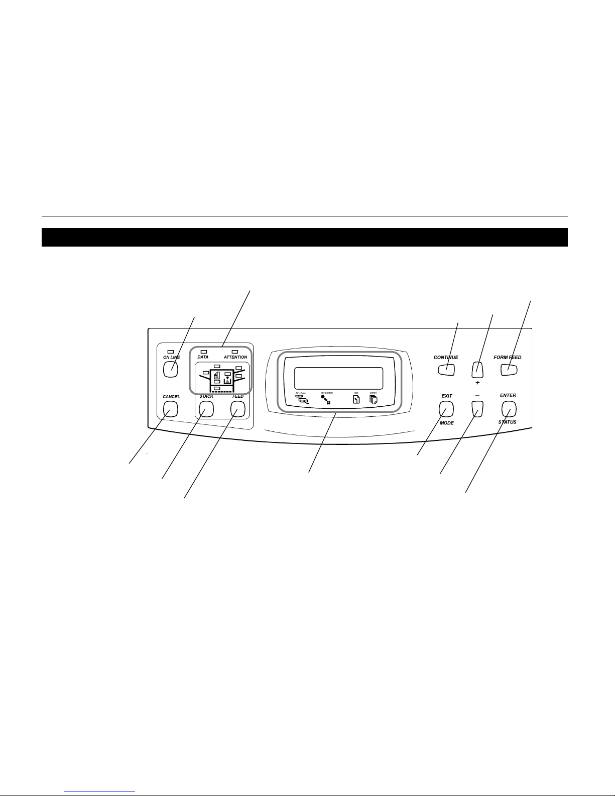
The printer control panel consists of indicators, a message display, and various keys.
Nearly all of the printer modes set using keys on the control panel are automatically recorded within
the printer, and are not lost even if power is turned off. The previous operational mode is therefore
restored when the printer's power is turned on again.
3 4
Symbolic Indicators
ON LINE Key
CANCEL Key
STACK Key
FEED Key
Message Display
CONTINUE/
3
Key
- key
FORM FEED/
4
Key
MODE/
EXIT Key
ENTER/STATUS key
+ key
Page 72

Chapter 2 Operating the Page Printer
2-3
Message Display
The message display displays the printer's operational mode. Messages which are displayed and
their meaning are given in the table below.
Message Meaning
Self test
The printer is self-testing and warming up after power-up and is not ready to
print.
Please wait
The printer is warming up and is not ready to print.
Ready
The printer is ready to print
Processing
The printer is processing print data or in the middle of printing.
Waiting
The last page remains unprinted. The printer waits awhile and eventually
generates a form feed allowing the last page to be printed. (The length of
time depends on the form feed timeout setting.)
The printing will begin immediately when the Form Feed key is pressed.
If a memory card is being used this can indicate the printer is waiting for data
to be written.
FormFeed TimeOut
An automatic form feed has been generated.
Paper Loading
After the paper feed cassette has been loaded into the paper feeder, the
paper feed position within the cassette is being readied.
Page 73

Control Panel
2-4
Interface Indicator
The interface indicator indicates the interface over which data is currently being received or was last
received. When an optional interface such as a network interface is installed in the printer, this
indicator displays the information in the table below depending on the interface used.
Display Description
PAR
Parallel interface
SER
Serial interface (RS-232C/RS-422A)
OPT
Optional interface
These indicators will flash while the printer is receiving data and continue flashing until the interface is
released even if data transmission is finished. The printer gives priority to data coming in over the
interface corresponding to the blinking indicator.
Resolution Indicator
This shows the current printing resolution. Resolution is set to 600 dpi (dot-per-inch), HP LaserJet 5Si
emulation, when shipped from the factory. The printer's resolution can be selected using the mode
select menu (See the menu hierarchy given at the end of this HANDBOOK.).
Page 74

Chapter 2 Operating the Page Printer
2-5
Paper Size Indicator
The paper size indicator indicates the paper size of the cassette currently installed in the printer
(factory setting is A3) or the paper size currently set for the multi-purpose tray. During printing the
paper size specified by the computer in data being sent to the printer will be displayed. (For example,
if the paper size in the cassette is B5 and reduced printing from A4 to B5 has been specified, B5 will
be displayed before and after printing but A4 will be displayed during printing.)
The following abbreviations are used to indicate the paper sizes.
Indicator Paper Size Indicator Paper Size
A3
ISO A3 (29.7 ´ 42 cm)
C4
ISO C4 (22.9 ´ 32.4 cm)*
A4
ISO A4 (21 ´ 29.7 cm)
C5
ISO C5 (16.2 ´ 22.9 cm)*
A5
ISO A5 (14.8 ´ 21 cm)
b5
ISO B5 (17.6 ´ 25 cm)*
A6
ISO A6 (10.5 ´ 14.8 cm)*
EX
Executive (7-1/4 ´ 10-1/2 inches)*
B4
JIS B4 (25.7 ´ 36.4 cm) [only the multi-purpose tray
B5
JIS B5 (18.2 ´ 25.7 cm) feeding]
B6
JIS B6 (12.8 ´ 18.2 cm)*
#6
Commercial 6-3/4
LT
Letter (8-1/2 ´ 11 inches) (3-5/8 ´ 6-1/2 inches)*
LD
Ledger (11 ´ 17 inches)
#9
Commercial 9
LG
Legal (8-1/2 ´ 14 inches) (3-7/8 ´ 8-7/8 inches)*
MO
Monarch (3-7/8 ´ 7-1/2 inches)*
CU
CUSTOM (11.7 x 17.7 inches)
BU
Business (4-1/8 ´ 9-1/2 inches)*
HA
Japanese Postcard (10 x 14.8 cm)
DL
ISO DL (11 ´ 22 cm)*
OH
Return Postcard (20 x 14.8 cm)
* Only when the multi-purpose tray or EF-100/UF-100 is installed.
Note______________________________________________________________________
Settings made by application software have priority over settings made from the control panel.
Page 75
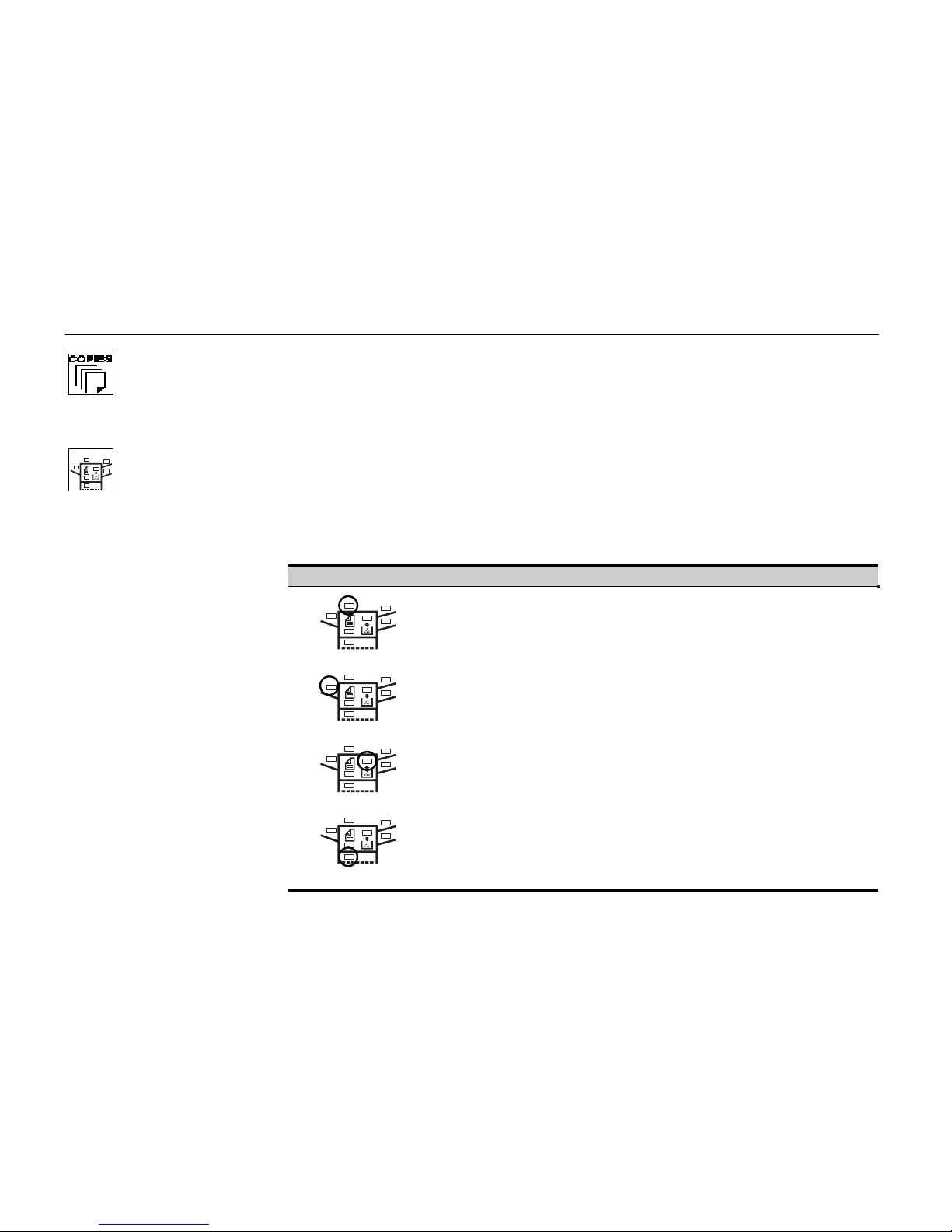
Control Panel
2-6
Copy Indicator
Indicates the number of copies set in the current interface (001 – 999), and the number is reduced as
printing proceeds.
Indicator
Refer to the table below for the names and meanings of indicators on the control panel.
Indicators on the Control Panel
Indicator Name Description
Face-down tray
indicator
Flashing: Indicates that paper is jammed near the facedown output tray.
Lit: indicates when printed pages are delivered to the facedown output tray.
Face-up tray
indicator
Flashing: Indicates that paper is jammed near the face-up
output tray.
Lit: indicates when printed pages are delivered to the faceup output tray.
Toner indicator Flashing: Indicates there is insufficient toner
Lit: Indicates that the printer is out of toner. Replace with
a new toner container.
Cassette feed
indicator
Flashing: Indicates that the cassette is not installed
properly or there is no paper in the cassette or that paper
is jammed in the paper feed cassette.
Lit: Indicates paper is being fed from the paper feeder
(ST-1000).
Page 76
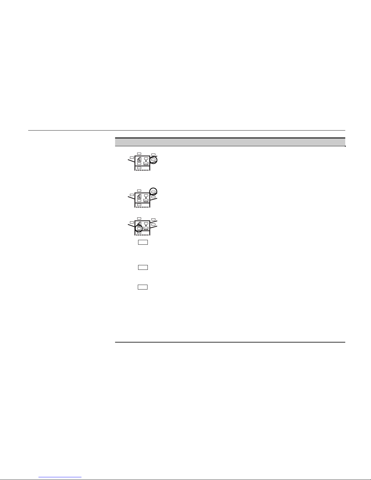
Chapter 2 Operating the Page Printer
2-7
Indicator Name Description
Multi-purpose feed
indicator
Flashing: Indicates that there is no paper in the tray or that
paper is jammed near the multi-purpose tray.
Lit: Indicates when paper is fed from the multi-purpose
feed tray.
Optional paper feeder
indicator
Flashing: Indicates that there is no paper in the optional
envelope feeder (EF-100) or universal feeder (UF-100); or
that paper is jammed near the paper feed opening.
Lit: Indicates that paper is being fed from the optional
envelope feeder (EF-100) or universal feeder (UF-100).
Duplex printing
indicator
Flashing: Indicates that paper is jammed in the optional
duplex printing unit (AD-31).
Lit: Indicates that the printer is printing in duplex mode
when the optional duplex printing unit (AD-31) is installed.
ON LINE
On-line indicator Lit: indicates that the printer is on-line. The printer prints
received data.
Off: The printer is offline. The printer stores but does not
print received data.
DATA
Data indicator Flashing: Indicates data transfer is taking place.
Lit: Indicates either that data is being processed, or that
data is being written to the memory card.
ATTENTION
Attention indicator This indicator indicates a problem that may be resolved by
the user.
Off: Indicates operations are normal.
Flashing: Indicates that the printer needs maintenance.
Check the message display for details and take
appropriate action.
Lit: This indicates that the printer cannot print due to no
paper in the cassette or similar reason. Check the
message display for details and take appropriate action.
Page 77
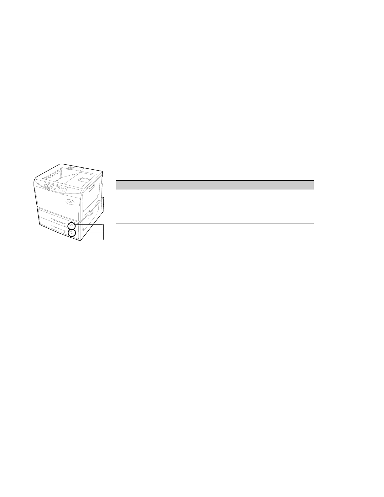
Control Panel
2-8
About the LED Indicator for the Paper Feed Cassettes
The size indicator plate on the front of the paper feed cassettes is illuminated by LED. This LED
indicates the status of the cassettes as follows depending on whether it is on, off or flashing.
LED Status Meaning
Flashing quickly Paper feed from this cassette is jammed.
Flashing slowly This cassette is out of paper.
Lit This cassette is currently selected.
Out
·
The cassette is not inserted properly.
·
The cassette is not currently selected.
Paper size indicators
Page 78
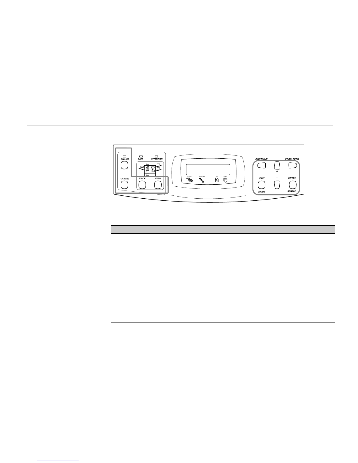
Chapter 2 Operating the Page Printer
2-9
Control Keys
The functions of each key are given in the table below.
Key Function
ON LINE
key Pauses and restarts printing. Data can be sent even while printing is paused.
(See page 2-16.)
CANCEL
key (1) This key can be used to cancel mode selection during mode selection or cancel printing
during printing. (See page 2-17.)
(2) It also cancels the alarm buzzer when it goes off. (See page 2-49.)
(3) Pressing this key while the message display reads
Ready
will cause the printer to
display
Sleeping
after about five seconds and the printer to enter sleep mode.
(See page 2-43.)
STACK
key This key selects whether to output paper face-down (printed side down) or face-up (printed
side up). It can also select optional output locations when corresponding options are
installed. (See page 2-14.)
FEED
key This key selects the paper feed cassette or multi-purpose tray as the paper source. It can
also select an optional if one is installed. (See page 2-15.)
3
Page 79

Control Panel
2-10
Key Function
CONTINUE
/
3
key
(1) This key forcibly cancels errors and resume printing when printing is halted due to
errors such as memory overflow.
(2) This key functions as the 3key during mode selection. It moves upward in the mode
select menu and moves the cursor left.
EXIT/MODE
key (1) This key interrupts settings when pressed during mode selection. (See page 2-23)
(2) This key is used to start and end the next mode selection and make settings.
This key is used in relation to the interface, emulation, fonts, character code set, memory
card operations and optional hardware, etc. (For details, see the menu hierarchy given at
the end of this manual.)
+ key
- key
These keys are used to select menus and change setting values while making settings with
the
MODE
key. Holding either key down activates an auto-repeat function causing menus
to continuously change.
FORM FEED
and 4key
(1) This key is used to forcibly print a form feed on the last page when a print timeout
occurs.
(2) This key functions as the 4key during mode selection. It moves downward in the menu
hierarchy and moves the cursor right (See page 2-23).
ENTER
/
STATUS
key
(1) This key confirms settings selected during mode selection.
(2) This key prints a status page (online). (See page 2-19.)
Notes_____________________________________________________________________
·
Menus set using these keys are enabled for the interface currently indicated on the message
display.
·
Settings made from the control panel may be automatically switched to different settings by
application software being used.
Page 80

Chapter 2 Operating the Page Printer
2-11
Operating Procedures
This section explains basic operations of the printer and procedures leading up to and including
printing.
Operating Precautions
·
Do not turn off power during printing. This may result in a paper jam or damage to the printer.
·
Do not open covers on the printer or covers of optional equipment or open the paper feed cassette
during printing.
·
Do not move the printer during printing.
·
Refrain from frequently plugging and unplugging the power plug from the power outlet even when
power is turned off.
·
Do not plug or unplug the power cord or printer cables while the printer's power is turned on.
·
Be sure that the printer's power is off when inserting or removing memory cards. Inserting or
removing a memory card while the printer's power is on may result in damage to the memory card
and/or the printer.
·
Be sure to carefully attach and detach paper feed cassettes and carefully open and close the top
cover.
·
Be sure to unplug the power cord from the power outlet and take precautions against dust
gathering on the printer by draping a cover over it when it is not in use.
Page 81
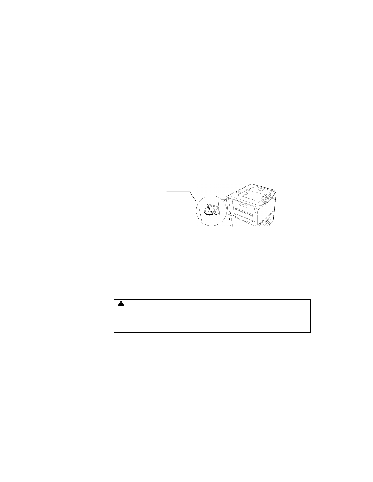
Operating Procedures
2-12
Switching Power On
Check that the power cord is securely plugged in at both ends. Check that the pr int er is connected to
the computer (See page 1-25).
1. Push the power switch to the ON ( | ) position.
2. Wait for the printer to warm up. During warm-up the message display indicates Self test.
3. At the end of the warm-up period, the ON LINE indicator lights, and the message display
indicates Ready.
The printer is now ready to print.
Note _____________________________________________________________________
If an error is detected wh ile the printer is warming up, the ATTENTION indicator will lig h t . A
message concerning the error will be displayed in the me ssage display. ( See Chapt er 4.)
Power Switch
CAUTION
If the printer will not be used for a short period of time (overright, etc.), turn the power switch
OFF(O). If it will not be used for an extended period of time (vacations, etc.), remove the
power plug from the outlet for safety purposes during the time the printer is not in use. Also
be sure to cover the printer so that dust does not accumulate.
Page 82

Chapter 2 Operating the Page Printer
2-13
Basic Printing Operations
The flow of basic operations to print is given below. Keys on the control panel are explained after that.
For details on using the
MODE
key, be sure to read the section “Mode Select Menu” at the end of this
manual in conjunction with this section.
1. Use the
MODE
key to set an emulation for the printer which conforms to the software being used.
This printer is shipped from the factory with emulation set to HP LaserJet 5Si.
2. Use the
MODE
key to select the font to use and paper direction.
3. Use the
FEED
key to select paper feeding from the cassette or the multi-purpose tray.
4. Use the
STACK
key to select the destination output tray.
5. Use the
MODE
key to set the number of printed copies.
6. Check that the message
Ready
appears in the message display and that the
ON LINE
indicator
lights, then make preparations to print from the computer.
Press the
FORM FEED
key if, after printing, the message
Waiting
appears in the message display.
Page 83
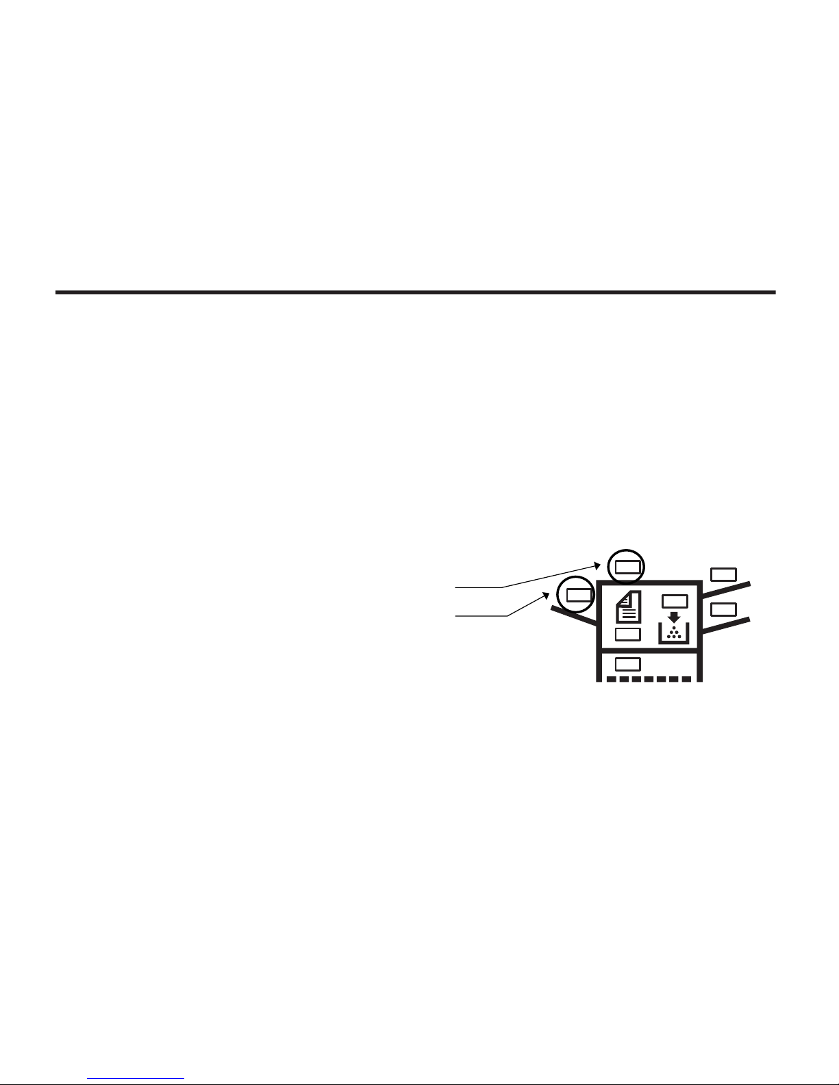
Operating Procedures
2-14
Selecting the Output Tray
Printed paper can be output on either the face-up output tray or the face-down output tray. Selecting
the face-up output tray will cause paper to be stacked with the printed surface facing up. Selecting the
face-down output tray will cause paper to be stacked with the printed surface facing down. Normally it
is more convenient to use the face-down output tray.
When the message
Ready or Add paper
appears in the message display, the output tray will be
switched every time the
STACK
key is pressed and the selected destination will appear in the
message display as follows.
Face-up tray
Face-down tray
The output tray currently selected will also flash on the indicator on the front panel.
Face-Down Tray Indicator
Face-Up Tray Indicator
Page 84

Chapter 2 Operating the Page Printer
2-15
Feed Selection
Use the
FEED
key to select whether to feed paper from one of the paper feed cassettes or from the
multi-purpose tray. If optional paper feeders (ST-1000 or EF-100/UF-100) are installed, any of these
can also be selected.
The
FEED
key can be used whenever the message display indicates
Ready
or
Add paper
.
Press the
FEED
key. The selection cycles and is momentarily displayed in the message display as:
Cassette 1
(Paper feeder's top cassette)
Cassette 2
(Paper feeder's bottom cassette)
Cassette 3
(Displayed when an optional feeder is installed [upper
cassette])
Cassette 4
(Displayed when an optional feeder is installed [lower cassette])
Cassette 5
(Displayed when a second optional feeder is installed [upper
cassette])
Cassette 6
(Displayed when a second optional feeder is installed [lower
cassette])
MP tray
(Printer's multi-purpose tray)
Universal feeder
(Displayed when an EF-100 or UF-100 is installed)
The cassette indicator corresponding to the selected cassette on the control panel will flash. Selecting
the paper feeder (ST-1000) cassette will also light the ready indicator on the front of that cassette.
Paper feed selections can also be made using the PRESCRIBE II PSRC command.
Page 85
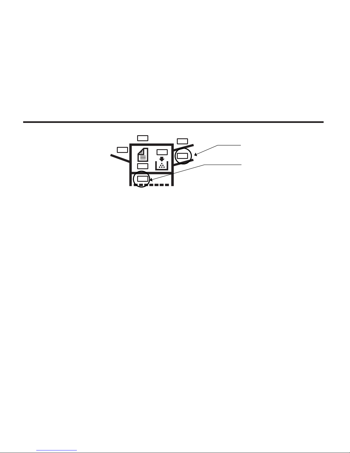
Operating Procedures
2-16
Switching Online/Offline
After printing starts, it is possible to interrupt printing to check whether the print job is coming out as
anticipated.
Pressing the
ON LINE
key during data processing will cause the
ON LINE
indicator to go out and
pressing it during printing will cause the printer to stop after the page currently being printed is
finished. During processing means anytime the messages
Processing, Waiting
or
FormFeed
TimeOut
are being displayed in the message display.
The printer continues to receive data even while the printer is offline while the message
Processing
is displayed.
Press the ON LINE key to bring the printer online again. The printer will come online and the
ON
LINE
indicator will light.
Read the section below on how to cancel printing.
MP (multi-purpose) tray indic at or
Cassette indicator
Page 86

Chapter 2 Operating the Page Printer
2-17
Canceling Printing
Perform the following procedure when you wish to cancel printing after it has begun.
1. Check if the message
Processing
is displayed in the message display.
2. Press the
ON LINE
key to take the printer offline.
3. Perform the necessary procedure on the computer to halt printing.
4. Press the
CANCEL
key.
5. The message
Print Cancel?
will appear in the message display and the interface to be
canceled will be displayed.
The following interfaces may be displayed.
Parallel
Serial
Option
(only when an optional interface is installed)
6. Selecting the interface to cancel using the + or - key and then press the
ENTER
key. Printing
from the interface selected will be stopped.
A few pages may be printed even after the
CANCEL
key is pressed as remaining data received
before the
CANCEL
key was pressed is printed.
The message
Print Cancel? Current job
will also be displayed when the
CANCEL
key is
pressed for the purpose of stopping the printing of status pages or font lists from the control
panel. Pressing the
ENTER
key will cause printing to stop after the printer finished printing the
current page.
Page 87

Operating Procedures
2-18
Press the
CANCEL
key again if you wish to stop the cancellation of printing.
Press the
ON LINE
key to put the printer back online to continue with other print jobs.
Notes_____________________________________________________________________
·
Canceling data from the computer using the
CANCEL
key will restore temporary settings to their
default values. (The same status resulting from executing the PRESCRIBE II RES command.)
·
It is impossible to cancel printing of just one side when printing in duplex mode using an optional
duplex printing unit (AD-31).
Page 88

Chapter 2 Operating the Page Printer
2-19
Status Printout
It is possible to print out and check the printer's current status including unit emulation, font, printing
range, and memory usage.
1. Check that the
ON LINE
indicator lit and that the message
Ready
is displayed in the message
display.
2. Press the
STATUS
key. The message display will read
Processing
, and a status page will be
printed. After it is finished printing, the message display will return to
Ready
.
An example of a printed status page is shown on the next page. Note that information on an actual
status page may differ slightly from this example.
Page 89
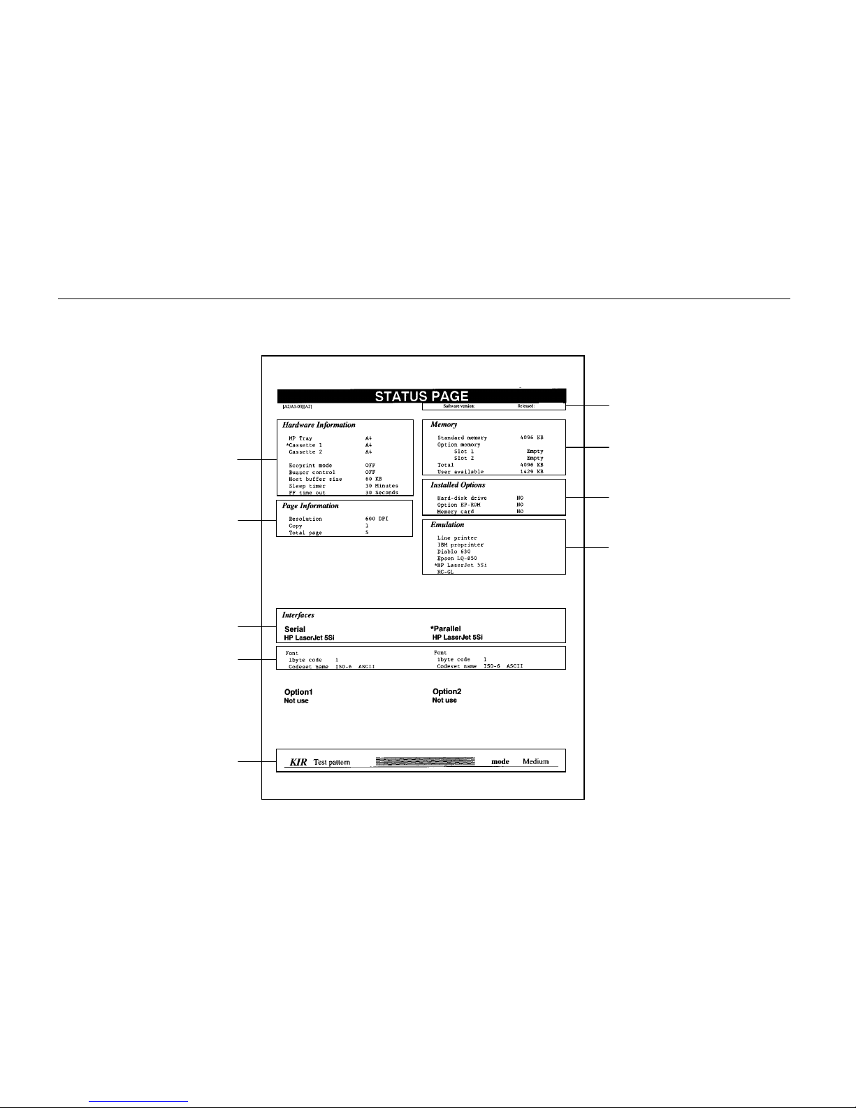
Operating Procedures
2-20
Sample Status Page
1
4562378
9
Page 90

Chapter 2 Operating the Page Printer
2-21
1 Software version
This information shows the software version and date of issue of the printer.
2 Hardware information
This information shows the currently selected paper feed source (indicated by an asterisk), paper size,
and main settings of the printer.
3 Page information
This information shows the currently selected resolution and number of copies.
4 Memory usage
This information shows the amount of total memory installed in the printer and the amount of currently
available memory.
5 Installation Options
This shows the options currently installed in the printer.
6 Emulation
This shows all available emulations and the currently selected emulation (marked with an asterisk).
The printer is shipped from the factory set to HP LaserJet 5Si emulation.
Page 91
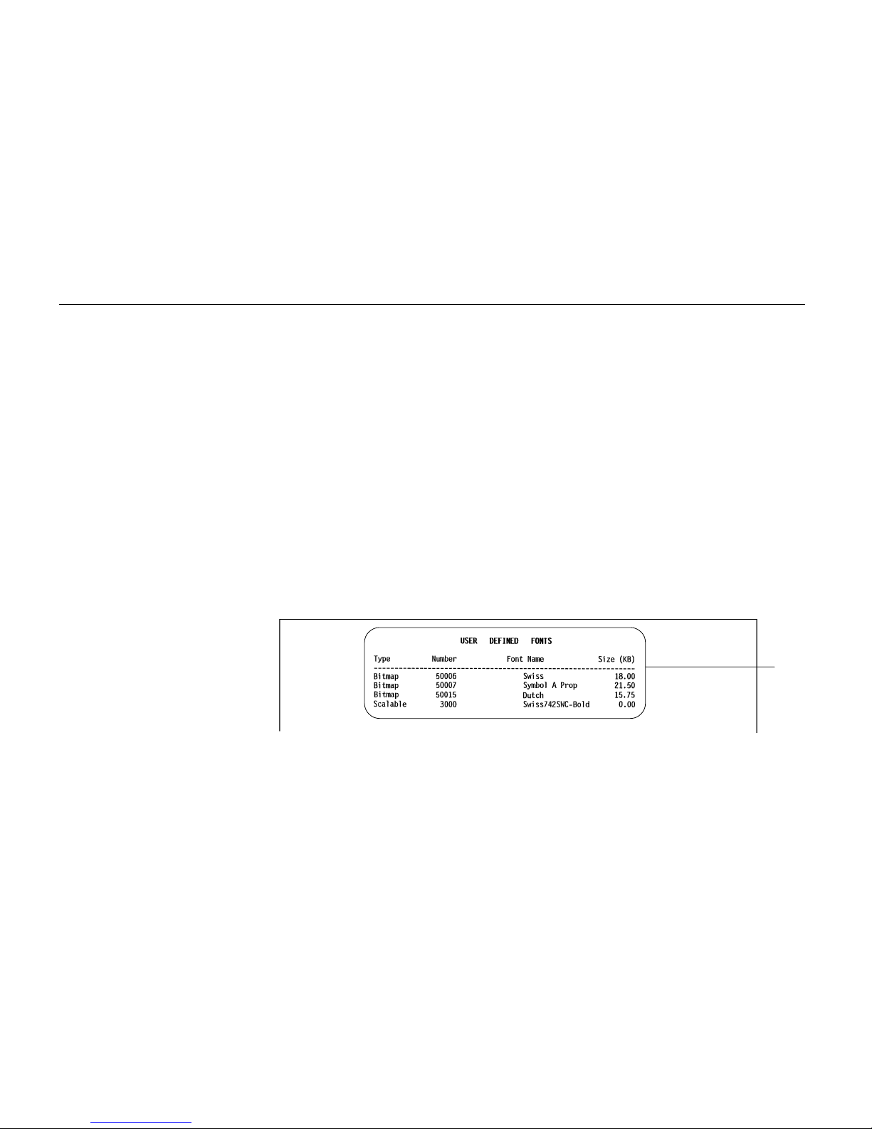
Operating Procedures
2-22
7 Interface information
This information shows all interfaces installed in the printer and the currently selected interface.
8 Fonts at startup (for each interface)
This shows the font automatically selected when the printer starts up (default font). It is possible to set
different fonts for the parallel interface and the serial interface. The figure on page 2-20 shows default
settings. The font is set to "1" (Courier bitmap font).
This also shows font information similar to the column below if an optional interface is installed.
9 KIR test pattern
This is used when setting the printer's KIR mode. For details, see page 2-45.
10 User font list
Following the status page, font listings are output which show the fonts which have been downloaded
to the printer from the computer.
10
Page 92

Chapter 2 Operating the Page Printer
2-23
Form Feed
Depending on the software, the message
Waiting
may be displayed in the message display when
you get to the end of a print job. This occurs when the software does not issue a final form feed to the
printer indicating the end of the print data. If you wait awhile,
FormFeed TimeOut
will be displayed
and the last page will be printed automatically. Pressing the
FORM FEED
key allows you to finish
printing immediately.
1. Check if the message display reads
Waiting
.
2. Press the
FORM FEED
key. The message display will now read
Processing
and the last
page will print.
Note______________________________________________________________________
The
Waiting
display may also appear due to interruptions in printed data while the computer is
processing data. Pressing the
FORM FEED
key unnecessarily when the message display reads
Waiting
will result in a form feed.
Mode Selection
The
MODE
key is used when making various mode settings and selections. For details, see the
section
Mode Selection Menu
beginning on the next page.
Page 93

Mode Selection Menu
2-24
Mode Selection Menu
This section explains the menu hierarchy used for all menus which can be set and selected using the
MODE
key. The
MODE
key can be used to display all of the menus in the table below. This mode
selection menu conforms to the menu hierarchy given at the end of this manual.
Pressing the
MODE
key initially displays menus at the top of the hierarchy.
Use the + and - keys to move between menus in the same level. The + key shows the next menu,
while the - key shows the previous one. Change levels by using the 3and 4keys. The 4key moves
to lower levels (sub-menus), while the 3key moves to higher levels.
Mode Selection Menu List
Menu Description Default Setting
Interface >
Selects the interface for which settings are to be made.
Settings from the mode select menu are applied to the
interface selected here.
Parallel
•
Depending on the computer connected, you can select
from any of
Nibble (high), Auto, Normal,
High speed
.
Nibble (high)
•
The following settings can be made for the serial
interface.
Baud rate 9600
Data bit 8
Stop bit 1
Parity None
Protocol DTR (pos.) & XON
(Continued on next page)
Page 94

Chapter 2 Operating the Page Printer
2-25
Menu Description Default Setting
Number of copies
Set the number of copies to be printed. This can be set up
to 999.
001
Emulation
>
Switches the printer emulation.
The mode can be further set if KC-GL emulation is set.
HP LaserJet 5Si
Font
>
Selects the print font. bitmap
Page set
Size reduction settings [See page 23] [CS] ® [CS]
Page orientation
Print direction settings [See page 23] Portrait
HARD DISK
>
The following settings can be made from sub-menus
when an optional hard disk unit is installed.
(For details, please read the hard disk unit instruction
manual.)
—
MEMORY CARD
>
The following operations can be performed from submenus on memory cards installed in the printer.
—
MP tray mode
>
The multi-purpose tray mode can be set to priority,
cassette or manual.
Pressing the
4
key will display
>
MP tray size
,
allowing you to set the paper size for the multi-purpose
tray.
First
A4 or Letter
Univ. paper size
This is displayed when an optional postcard feeder (EF-
100) or universal feeder (UF-100) is installed. The paper
size can be set for either of these feeders.
DL
Paper Type
This can be changed depending on the thickness of the
paper to be printed on.
Thin
: 60 to 70 g/m
2
Normal
: 70 to 80 g/m
2
Thick
: 90 to 200 g/m
2
To prevent paper jams, be sure to feed thick paper from
the multi-purpose tray and output on the face-up tray. For
details on paper which can be used, see
Appendix B
.
Normal
(Continued on next page)
Page 95

Mode Selection Menu
2-26
Menu Description Default Setting
Duplex mode
This is displayed when an optional duplex printing unit (AD-
31) is installed. Select the duplex printing mode (long edge
or short edge).
None
Others >
The following sub-menus can be displayed by pressing the
4
key and then the + or – key.
Automatic form feed timeout setting
Sleep timer setting [See page 2-43.]
Receive data damping [See page 2-44.]
Printer reset
Line feed setting [See page 2-23.]
Carriage return setting
Display total number of printed pages
KIR mode setting
Ecoprint Mode setting
Page protection mode
Resolution setting
Resource setting
Print density setting
Alarm (buzzer) setting
Print area correction
Service (for service personnel)
30 sec.
30 min.
–
–
LF only
CR only
–
Medium
Off
Auto
600
Off
03
Off
00
–
Main items within these menus are explained beginning on the next page. For details on other menus,
see the
Mode Select Menu
diagram at the end of this HANDBOOK.
Page 96

Chapter 2 Operating the Page Printer
2-27
Configuring Interfaces
The printer is equipped with both a parallel and serial interface. Independent settings can be made for
each interface. Optional interfaces can also be installed.
To configure each interface, press the
MODE
key and use the + or - key to select the interface you
wish to make settings for.
Note______________________________________________________________________
This interface selection does not select which interface data will be received from. The printer
automatically selects that interface.
Parallel Interface
The parallel interface mode of this printer supports a bi-directional/high-speed mode. Normally, this
interface is used under the default setting
Nibble (high)
, see
Appendix C
. After setting the
interface, be sure to reset the printer or turn the power off at least once. The new setting will be
enabled thereafter.
Page 97

Reduction (Page Set)
2-28
Emulation Selection
The following emulations can be selected for this printer. The emulation selected is stored even while
the printer's power is off.
Line printer
IBM Proprinter
Diablo 630
Epson LQ-850
HP LaserJet 5Si (Default setting)
KC-GL
KC-GL Emulation
The following settings can be made from the sub-menu when KC-GL emulation is selected.
Display Description
> KC-GL Pen width
The width of pens (1) through (8) can be set in 1-dot increments from 01 to 99.
After selecting the pen on this sub-menu, you can also display and select the
width set for that pen on a lower menu.
> KC GL Page set
Any of the following page sizes can be set:
A2, A1, A0, B3, B2, B1,
B0, SPSZ
(custom size specified using the SPSZ command). The selected
page size will be automatically reduced to the actual paper size being used.
Page 98

Chapter 2 Operating the Page Printer
2-29
Reduction (Page Set)
Make settings on the page set menu to print at a reduced size. This menu is used to set the source
paper size and the paper size to use after reduction. These settings can be made from within
programs or files using the PRESCRIBE SPSZ command.
Notes_____________________________________________________________________
·
Printed results when making reductions differ from equivalent size printing. Sometimes the line
width of characters may not be consistent or lines may appear in figures or image patterns.
·
Landscape feeding while making reductions is possible from the multi-purpose tray in priority
mode.
Bring up the page set menu. The following display will appear.
Source size indicator···
This is the paper size before reduction.
This must be the same as the paper size set for print data from the computer.
Target size indicator···
This is the paper size after reduction.
This must be the same as the paper size set for the feed cassette.
Target size indicator
Source size indicator
Page set
[CS] ® [CS]
Page 99

Reduction (Page Set)
2-30
It is possible to set the following paper sizes (envelope) when using the PRESCRIBE SPSZ
command. The message display will show the messages given in the following table. For details on
the SPSZ command, see
Chapter 6
.
Source Size-Target Size Combinations
Source Size Indicator Target Size Indicator Reduction/Enlargement Ratio
CS CS
CS 98%
100%
98%
LG
Legal size
(8.5 ´ 14 inches)
LG
LG 98%
100%
98%
LT
Letter size
(8.5 ´ 11 inches)
LT
A4
LT 98%
100%
94%
98%
LD
Ledger size
(12 ´ 15.5 inches)
LD
LD 98%
100%
98%
A5
(14.8 ´ 21 cm)
A5
A5 98%
100%
98%
B5
(18.2 x 25.7 cm)
B5
B5 98%
A5
100%
98%
81%
(Continued on next page)
Page 100

Chapter 2 Operating the Page Printer
2-31
Source Size Indicator Target Size Indicator Reduction/Enlargement Ratio
A4
(21 ´ 29.7 cm)
A4
LT
B5
A4 98%
100%
94%
86%
98%
B4
(25.7 ´ 36.4 cm)
B4
B5
A4
B4 98%
100%
70%
81%
98%
A3
(29.7 ´ 42 cm)
A3
A4
B4
A3 98%
100%
70%
86%
98%
 Loading...