

Page 1
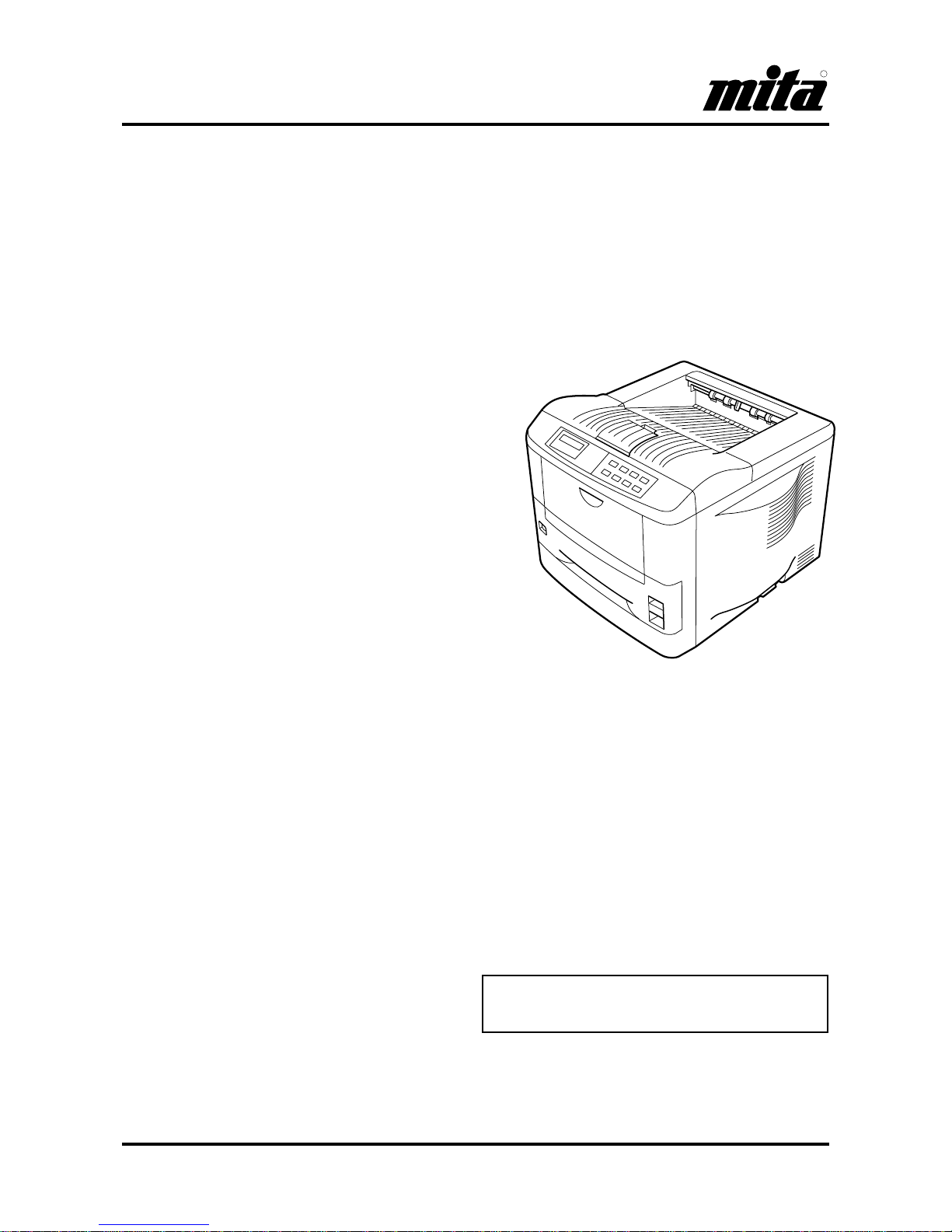
DP-1400
DP-1800
INSTRUCTION HANDBOOK
Please read this instruction handbook before using the
printer.
Keep it close to the printer for easy referenc e.
Laser Printer
Page 2

Page 3
Introduction
i
Please read this instruction handbook before using the printer .
Keep it close to the printer for easy reference.
The sections of this handbook and parts of the printer marked with symbols are safety warnings meant to protect the user, other individuals and surrounding objects, and ensure correct and safe usage of the printer. The
symbols and their meanings are indicated below.
DANGER: Indicates that serious injury or even death will very possibly result from insufficient attention to
or incorrect compliance with the related points.
WARNING: Indicates that serious injury or even death may result from insufficient attention to or incorrect
compliance with the related points.
CAUTION: Indicates that personal injury or mechanical damage may result from insufficient attention to or
incorrect compliance with the related points.
Symbols
The symbol indicates that the related section includes safely warnings. Specific points of attention are indicated inside the symbol.
............[General warning]
............[Warning of danger of electrical shock]
............[Warning of high temperature]
The symbol indicates that the related section includes information on prohibited actions. Specific of the prohibited action are indicated inside the symbol.
............[Warning of prohibited action]
............[Disassembly prohibited]
The ●●●● symbol indicates that the related section includes information on actions which must be performed. Spe-
cifics of the required action are indicated inside the symbol.
............[Alert of required action]
............[Remove the power plug from the outlet]
............[Always connect the printer to an outlet with a ground connection]
Please contact your service representative to order a replacement if the safety warnings in the handbook are
illegible or if the handbook itself is missing.(fee required)
Page 4

Introduction
ii
Caution
NO LIABILITY IS ASSUMED FOR ANY DAMAGE CAUSED BY IMPROPER INSTALLATION.
SOFTWARE USED WITH THIS PRINTER MUST SUPPORT THE PRINTER'S EMULATION MODE. The printer is
factory-set to emulate the PCL 6. The emulation mode can be changed by following the procedures described in Chapter
2.
Notice on Software
SOFTWARE USED WITH THIS PRINTER MUST SUPPORT THE PRINTER'S NATIVE MODE OR ONE OF ITS
EMULATION MODES.
Notice
The information in this manual is subject to change without notification. Additional pages may be inserted in future
editions. The user is asked to excuse any technical inaccuracies or typographical errors in the present edition.
No responsibility is assumed if accidents occur while the user is following the instructions in this manual. No responsibility is assumed for defects in the printer's firmware (contents of its read-only memory).
This manual, any copyrightable subject matter sold or provided with or in connection with the sale of the page printer,
are protected by copyright. All rights are reserved. Copying or other reproduction of all or part of this manual, any
copyrightable subject matter without the prior written consent of our company is prohibited. Any copies made of all or
part of this manual, any copyrightable subject must contain the same copyright notice as the material from which the
copying is done.
Regarding Tradenames
PRESCRIBE is a registered trademark of our company. PRESCRIBE 2e, KPDL, and KIR2 are trademarks of our company.
Diablo 630 is a product of Xerox Corporation. IBM Proprinter X24E is a product of International Business Machines
Corporation. Epson LQ-850 is a product of Seiko Epson Corporation.
Hewlett-Packard, PCL, and PJL are registered trademarks of Hewlett-Packard Company. Centronics is a trade name of
Centronics Data Computer Corp. PostScript is a registered trademark of Adobe Systems Incorporated. Macintosh is a
registered trademark of Apple computer, Inc. AppleTalk is a trademark of Apple Computer, Inc. Microsoft, Windows, and
MS-DOS are registered trademarks of Microsoft Corporation. PowerPC is a trademark of International Business
Machines Corporation. E
NERGY STAR
is a U.S. registered mark.
This page printer uses PeerlessPrintXL to provide the HP LaserJet compatible PCL6 language emulation. PeerlessPrintXL is a trademark of The Peerless Group, Redondo Beach, CA 90278, U.S.A.
This product was developed using the Tornado™ Real Time Operating System and Tools from Wind River Systems.
Contains UFST
™
and MicroType® from Agfa Corporation.
Pixel Magic is a trademark of Oak Technology, Inc.
Page 5

Introduction
iii
IBM PROGRAM LICENSE AGREEMENT
THE DEVICE YOU HAVE PURCHASED CONTAINS ONE OR MORE SOFTWARE PROGRAMS ("PROGRAMS")
WHICH BELONG TO INTERNATIONAL BUSINESS MACHINES CORPORATION ("IBM"). THIS DOCUMENT
DEFINES THE TERMS AND CONDITIONS UNDER WHICH THE SOFTWARE IS BEING LICENSED TO YOU BY
IBM. IF YOU DO NOT AGREE WITH THE TERMS AND CONDITIONS OF THIS LICENSE, THEN WITHIN 14 DAYS
AFTER YOUR ACQUISITION OF THE DEVICE YOU MAY RETURN THE DEVICE FOR A FULL REFUND. IF YOU
DO NOT SO RETURN THE DEVICE WITHIN THE 14 DAYS, THEN YOU WILL BE ASSUMED TO HAVE AGREED
TO THESE TERMS AND CONDITIONS.
The Programs are licensed not sold. IBM, or the applicable IBM country organization, grants you a license for the
Programs only in the country where you acquired the Programs. You obtain no rights other than those granted you under
this license.
The term "Programs" means the original and all whole or partial copies of it, including modified copies or portions
merged into other programs. IBM retains title to the Programs. IBM owns, or has licensed from the owner, copyrights in
the Programs.
1. License
Under this license, you may use the Programs only with the device on which they are installed and transfer possession
of the Programs and the device to another party.
If you transfer the Programs, you must transfer a copy of this license and any other documentation to the other party.
Your license is then terminated. The other party agrees to these terms and conditions by its first use of the Program.
You may not:
1) use, copy, modify, merge, or transfer copies of the Program except as provided in this license;
2) reverse assemble or reverse compile the Program; or
3) sublicense, rent, lease, or assign the Program.
2. Limited Warranty
The Programs are provided "AS IS."
THERE ARE NO OTHER WARRANTIES COVERING THE PROGRAMS (OR CONDITIONS), EXPRESS OR
IMPLIED, INCLUDING, BUT NOT LIMITED TO, THE IMPLIED WARRANTIES OF MERCHANTABILITY AND
FITNESS FOR A PARTICULAR PURPOSE.
Some jurisdictions do not allow the exclusion of implied warranties, so the above exclusion may not apply to you.
SUPPLEMENT TO AGREEMENT FOR SOFTWARE BUNDLING AND DISTRIBUTION FOR ALDC
3. Limitation of Remedies
IBM's entire liability under this license is the following;
1) For any claim (including fundamental breach), in any form, related in any way to this license, IBM's liability will be
for actual damages only and will be limited to the greater of:
a) the equivalent of U.S.$25,000 in your local currency; or
b) IBM's then generally available license fee for the Program
This limitation will not apply to claims for bodily injury or damages to real or tangible personal property for which IBM
is legally liable.
IBM will not be liable for any lost profits, lost savings, or any incidental damages or other economic consequential
damages, even if IBM, or its authorized supplier, has been advised of the possibility of such damages. IBM will not be
liable for any damages claimed by you based on any third party claim. This limitation of remedies also applies to any
developer of Programs supplied to IBM. IBM's and the developer's limitations of remedies are not cumulative. Such
developer is an intended beneficiary of this Section. Some jurisdictions do not allow these limitations or exclusions, so
they may not apply to you.
Page 6

Introduction
iv
4. General
You may terminate your license at any time. IBM may terminate your license if you fail to comply with the terms and
conditions of this license. In either event, you must destroy all your copies of the Program. You are responsible for
payment of any taxes, including personal property taxes, resulting from this license. Neither party may bring an action,
regardless of form, more than two years after the cause of action arose. If you acquired the Program in the United States,
this license is governed by the laws of the State of New York. If you acquired the Program in Canada, this license is
governed by the laws of the Province of Ontario. Otherwise, this license is governed by the laws of the country in which
you acquired the Program.
Typeface Trademark Acknowledgement
All resident fonts in this printer are licensed from Agfa Corporation.
Helvetica, Palatino and Times are registered trademarks of Linotype-Hell AG.
ITC Avant Garde Gothic, ITC Bookman, ITC ZapfChancery and ITC Zapf Dingbats are registered trademarks of International Typeface Corporation.
Agfa Japan License Agreement Guidelines
1. “Software” shall mean the digitally encoded, machine readable, scalable outline data as encoded in a special format
as well as the UFST Software.
2. You agree to accept a non-exclusive license to use the Software to reproduce and display weights, styles and versions
of letters, numerals, characters and symbols (“Typefaces”) solely for your own customary business or personal purposes at the address stated on the registration card you return to Agfa Japan. Under the terms of this License
Agreement, you have the right to use the Fonts on up to three printers. If you need to have access to the fonts on more
than three printers, you need to acquire a multi-user license agreement which can be obtained from Agfa Japan. Agfa
Japan retains all rights, title and interest to the Software and Typefaces and no rights are granted to you other than
a License to use the Software on the terms expressly set forth in this Agreement.
3. To protect proprietary rights of Agfa Japan, you agree to maintain the Software and other proprietary information
concerning the Typefaces in strict confidence and to establish reasonable procedures regulating access to and use of
the Software and Typefaces.
4. You agree not to duplicate or copy the Software or Typefaces, except that you may make one backup copy. You agree
that any such copy shall contain the same proprietary notices as those appearing on the original.
5. This License shall continue until the last use of the Software and Typefaces, unless sooner terminated. This License
may be terminated by Agfa Japan if you fail to comply with the terms of this License and such failure is not remedied
within thirty (30) days after notice from Agfa Japan. When this License expires or is terminated, you shall either
return to Agfa Japan or destroy all copies of the Software and Typefaces and documentation as requested.
6. You agree that you will not modify, alter, disassemble, decrypt, reverse engineer or decompile the Software.
7. Agfa Japan warrants that for ninety (90) days after delivery, the Software will perform in accordance with Agfa
Japan-published specifications, and the diskette will be free from defects in material and workmanship. Agfa Japan
does not warrant that the Software is free from all bugs, errors and omissions.
THE PARTIES AGREE THAT ALL OTHER WARRANTIES, EXPRESSED OR IMPLIED, INCLUDING WARRANTIES OF FITNESS FOR A PARTICULAR PURPOSE AND MERCHANTABILITY, ARE EXCLUDED.
8. Your exclusive remedy and the sole liability of Agfa Japan in connection with the Software and Typefaces is repair or
replacement of defective parts, upon their return to Agfa Japan.
IN NO EVENT WILL AGFA JAPAN BE LIABLE FOR LOST PROFITS, LOST DATA, OR ANY OTHER INCIDENTAL OR CONSEQUENTIAL DAMAGES, OR ANY DAMAGES CAUSED BY ABUSE OR MISAPPLICATION OF
THE SOFTWARE AND TYPEFACES.
9. New York, U.S.A. law governs this Agreement.
10. You shall not sublicense, sell, lease, or otherwise transfer the Software and/or Typefaces without the prior written
consent of Agfa Japan.
11. Use, duplication or disclosure by the Government is su bject to restrictions as set forth in the Rights in Technical Data
and Computer Software clause at FAR 252-227-7013, subdivision (b)(3)(ii) or subparagraph (c)(1)(ii), as appropriate.
Further use, duplication or disclosure is subject to restrictions applicable to restricted rights software as set forth in
FAR 52.227-19 (c)(2).
Page 7

Introduction
v
12. YOU ACKNOWLEDGE THAT YOU HAVE READ THIS AGREEMENT, UNDERSTAND IT, AND AGREE TO BE
BOUND BY ITS TERMS AND CONDITIONS. NEITHER PARTY SHALL BE BOUND BY ANY STATEMENT OR
REPRESENTATION NOT CONTAINED IN THIS AGREEMENT. NO CHANGE IN THIS AGREEMENT IS
EFFECTIVE UNLESS WRITTEN AND SIGNED BY PROPERLY AUTHORIZED REPRESENTATIVES OF EACH
PARTY. BY OPENING THIS DISKETTE PACKAGE, YOU AGREE TO ACCEPT THE TERMS AND CONDITIONS
OF THIS AGREEMENT.
FCC statement
This device complies with Part 15 of the FCC Rules. Operation is subject to the following two conditions: (1)
This device may not cause harmful interference, and (2) this device must accept any interference received,
including interference that may cause undesired operation.
Note
This equipment has been tested and found to comply with the limits for a Class B digital device, pursuant to
Part 15 of the FCC Rules. These limits are designed to provide reasonable protection against harmful interference in a residential installation. This equipment generates, uses, and can radiate radio frequency energy
and, if not installed and used in accordance with the instructions, may cause harmful interference to radio
communications. However, there is no guara ntee that interference will not occur in a part icular installation.
If this equipment does cause harmful interference to radio or television reception, which can be determined
by turning the equipment off and on, the user is encouraged to try to correct the interference by one or more
of the following measures:
❒
Reorient or relocate the receiving antenna.
❒
Increase the separation between the equipment and receiver.
❒
Connect the equipment into an outlet on a circuit different from that to which the receiver is connected.
❒
Consult the dealer or an experienced radio/TV technician for help.
Changes or modifications not expressly approved by the manufacturer for compliance could void the user's
authority to operate the equipment.
Shielded circular cable should be used for interfacing with the computer.
Caution to user
Any modification without prior permission may cause harmful interference.
If any modification/change is introduced to this equipment without prior permission, we as the manufacturer cannot guarantee compliance with FCC rules.
To use equipment which does not comply with FCC rules is prohibited.
The printer may be optionally installed with the following units:
Conforming to the Class B limits
❒
EF-100 Envelope Feeder
❒
AD-34 Duplexer (for DP-1400/DP-1800)
❒
HS-100 Paper Handler/Stacker (for DP-1400/DP-1800)
❒
ST-520/ST-520mini Paper Feeder (for DP-1400/DP-1800)
Page 8
Introduction
vi
Interface connectors
Important note on the interface connectors
Be sure to turn off printer power before connecting or disconnecting an interface cable to the printer. For protection against static discharge which may be applied to the printer's internal electronics through the interface connector(s), keep any interface connector which is not in use capped using the protective cap supplied.
☛
Use shielded interface cable.
Safety information
Laser safety
This printer is certified as a Class 1 laser product under the U.S. Department of Health and Human Services
(DHHS) Radiation Performance Standard according to Radiation Control for Health and Safety Act of 1968.
This means that the printer does not produce hazardous laser radiation. Since radiation emitted inside the
printer is completely confined within protective housings and external covers, the laser beam cannot escape
from the printer during any phase of user operation.
Laser notice
This printer is certified in the U.S. to conform to the requirements of DHHS 21 CFR Subchapter for Class I
(1) laser products, and elsewhere is certified as a Class I laser product conforming to the requirements of IEC
825-1
Use of controls or adjustments or performance of procedures other than those specified herein may result in
hazardous radiation exposure.
CAUTION
Laser radiation when open. DO NOT ST ARE INTO BEAM OR VIEW DIRECTL Y WITH OP TICAL INSTRUMENTS.
(U.S.A./Canada)
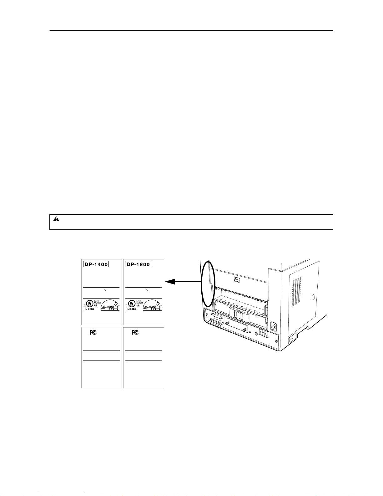
The labels shown are affixed to the DP-1800 and the DP-1400.
60Hz 7.8A120V
PRINTER
THIS LASER PRODUCT CONFIRMS TO THE APPLICABLE
REQUIREMENTS OF FEDERAL REGULATIONS 21 CFR
CHAPTER 1, SUBCHAPTER J.
MITA INDUSTRIAL CO.,LTD.
2-28 1-CHOME TAMATSUKURI
CHUO-KU OSAKA JAPAN
MADE IN JAPAN
MANUFACTURED
YM
MACHINE No.
60Hz 5.8A120V
PRINTER
THIS LASER PRODUCT CONFIRMS TO THE APPLICABLE
REQUIREMENTS OF FEDERAL REGULATIONS 21 CFR
CHAPTER 1, SUBCHAPTER J.
MITA INDUSTRIAL CO.,LTD.
2-28 1-CHOME TAMATSUKURI
CHUO-KU OSAKA JAPAN
MADE IN JAPAN
MANUFACTURED
YM
MACHINE No.
ATTENTION
POUR PRÉVENIR LES CHOCS
ÉLECTRIQUES, COUPER L,ALIMENTATION
AVANT DE REMPLACER LE FUSIBLE.
CAUTION
REMOVE POWER CORD BEFORE
SERVICE AND FUSE REPLACEMENT.
This Class B digital apparatus complies
with Canadian ICES-.
Cet appareil numrique de la classe B est
conforme la norme NMB- du Canada.
PRECAUCION
RETIRE EL CORDON ELECTRICO ANTES
DE REALIZAR SERVICIO O REEMPLAZAR
EL FUSIBLE.
FOR HOME OR OFFICE USE
Tested To Comply
With FCC Standards
This device complies with Part of the CC Rules.
Operation is subject to the following two conditions
() This device may not cause harmful interference,
and () this device must accept any interference
received, including interference that may cause
undesired operation.
ATTENTION
POUR PRÉVENIR LES CHOCS
ÉLECTRIQUES, COUPER L,ALIMENTATION
AVANT DE REMPLACER LE FUSIBLE.
CAUTION
REMOVE POWER CORD BEFORE
SERVICE AND FUSE REPLACEMENT.
This Class B digital apparatus complies
with Canadian ICES-.
Cet appareil numrique de la classe B est
conforme la norme NMB- du Canada.
PRECAUCION
RETIRE EL CORDON ELECTRICO ANTES
DE REALIZAR SERVICIO O REEMPLAZAR
EL FUSIBLE.
FOR HOME OR OFFICE USE
Tested To Comply
With FCC Standards
This device complies with Part of the CC Rules.
Operation is subject to the following two conditions
() This device may not cause harmful interference,
and () this device must accept any interference
received, including interference that may cause
undesired operation.
DP-1400
DP-1800
Page 9

Introduction
vii
CDRH regulations
The Center of Devices and Radiological Health (CDRH) of the U.S. Food and Drug Administration implemented regulations for laser products on August 2, 1976. These regulations apply to laser products manufactured after August 1, 1976. Compliance is mandatory for products marketed in the United States. A label
indicating compliance with the CDRH regulations must be attached to laser products marketed in the
United States.
Ozone concentration
The printers generate ozone gas (O3) which may concentrate in the place of installation and cause an
unpleasant smell. To minimize concentration of ozone gas to less than 0.1 ppm, we recommend you not to
install the printer in a confined area where ventilation is blocked.
Page 10

Introduction
viii
Declaration of Conformity (U.S.A.)
Model Number: Page Printer DP-1400/DP-1800
(as tested with enhancement optional units: EF-100, ST-510, AD-34, and HS-100
etc.)
Trade Name: Mita
Responsible Party: MITA COPYSTAR AMERICA, INC.
Address: 225 Sand Road, P.O. Box 40008 Fairfield New Jersey 07004-0008
Telephone number: (973)808-8444
Fax number: (973)882-6000
This device complies with Part 15 of the FCC Rules, Operation is subject to the following two conditions: (1)
This device may not cause harmful interference, and (2) this device must accept any interference received,
including interference that may cause undesired operation.
Page 11

Introduction
ix
This page is intentionally left blank
Page 12

Introduction
x
Canadian Department of Communications compliance statement
This Class B digital apparatus complies with Canadian ICES-003.
Avis de conformité aux normes du ministère des Communications du
Canada
Cet appareil numérique de la classe B est conforme à la norme NMB-003 du Canada.
ISO 7779
Maschinenlärminformationsverordnung 3. GSGV, 18.01.1991: Der höchste Schalldruckpegel beträgt 70
dB(A) oder weniger gemäß ISO 7779.
Disclaimer
We shall have no liability or responsibility to customers or any other person or entity with respect to any
liabi lity, l oss or d amag e cau sed o r al leged to be caus ed di rect ly or i ndi rect ly by equip ment sol d or f urnis hed
by us, including but not limited to, any interruption of service, loss of business or anticipatory profits, or consequential damages resulting from the use or operation of the equipment or software.
Page 13
Introduction
xi
Prolonged Non-Use and Moving the Printer
Prolonged Non-use
If you ever leave the printer unused for a long period of time, remove the power cord from the wall outlet.
We recommend you consult with your dealer about the additional actions you should take to avoid possible
damages that may occur when the printer is used next time.
Moving the Printer
When you move the printer:
❒
Move it gently.
❒
Keep it as level as possible, to avoid spilling toner inside the printer.
❒
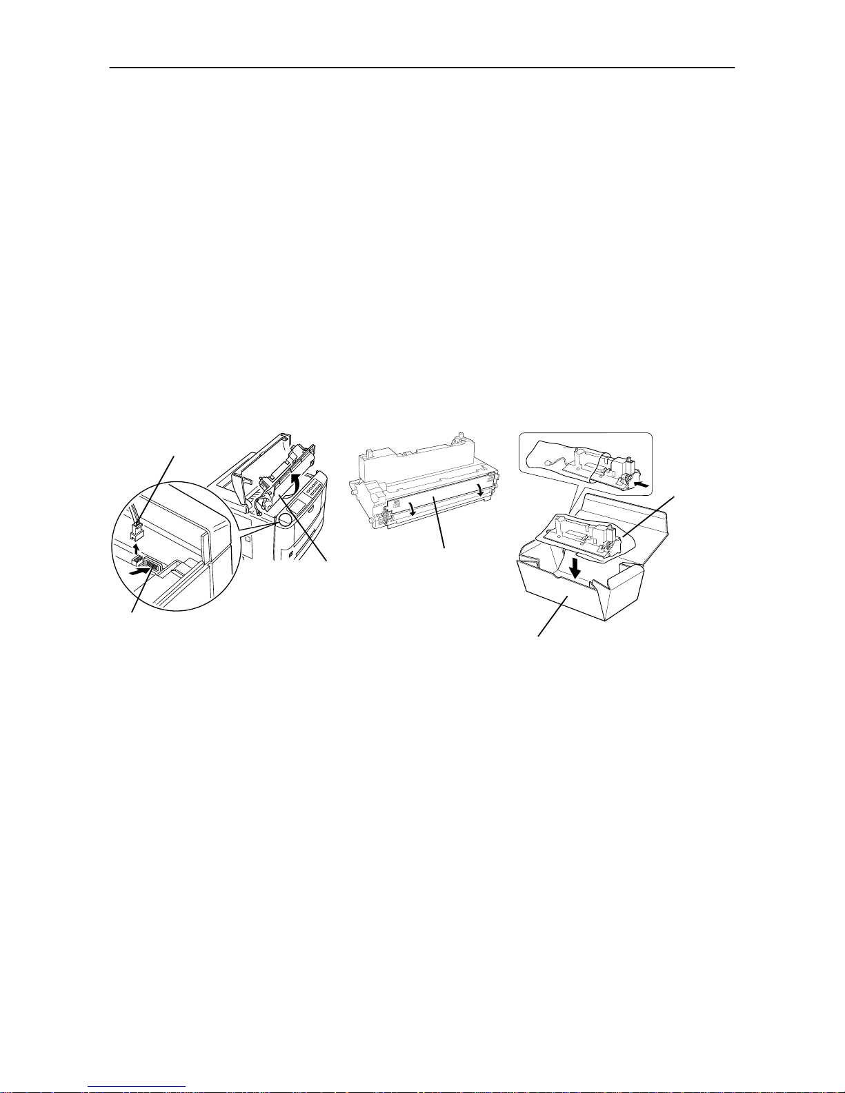
If you need to move the printer to another location, first remove the toner container, developer unit, and
waste toner bottle. After removing the developer unit from the printer, wrap it in the supplied plastic bag
and place it into the box in which the toner container is packaged. Make sure that the waste toner bottle
is securely capped and place it in the plastic bag together with the toner container. Be sure to consult a
serviceman before attempting long-distance transportation of the printer.
(1)
Remove the developer unit.
(2)
Close the protect cover.
(3)
Pack the developer unit.
To reinstall the developer unit in the printer, use the reverse procedure of the above.
Protect cover
Toner container box
Plastic
bag
(supplied)
1. Disconnect
2. Push
Developer unit
Page 14

Introduction
xii
As an ENERGY STAR Partner, Mita (Mita Copystar America, Inc.) has
Determined that this product meets the ENERGY STAR guidelines for
energy efficiency.
* ENERGY STAR is a U.S. registered mark.
Page 15

Introduction
xiii
Introduction
The laser printer has many extremely desirable features. It has been designed to make a contribution to a
cleaner environment as well as to represent the latest generation of page printer technology.
Maintenance Features
• Compact design
Thanks to the inboard cassette configuration, the printer requires no more space than the average computer.
• Ultra long life modules
The drum, developer, and fuser have been designed for ultra long life.
• Amorphous silicon drum
The drum has been developed using our unique ceramic technology using amorphous silicon.
Print Engine Features
• Superb print quality
Using 1200 dots per inch in "Fast 1200 mode" or "Fine 1200 mode", the printout is close to typeset quality.
Also, with KIR technology, high quality printing can be achieved even at 600 dpi and 300 dpi.
•High speed
A4 sizes typically print at the rate of 18 (14 for the DP-1400) pages per minute. (Actual time varies according to page complexity)
• Large paper capacity
Approximately 250 sheets can be loaded into the paper cassette, and about 100 sheets can be loaded into
the MP tray.
• Wide variety of print media
As well as standard paper, the printer will print on OHP film, labels and other types of special purpose
media.
•Sleep mode
Conserves energy during the printer's idle periods.
•Draft mode
Extends the toner yield by reducing the amount of toner used on the page.
• Standard bi-directional parallel interface
Supports high-speed data exchange with the computer.
Page 16

Introduction
xiv
Software Features
• Wide variety of available fonts
The printer comes with 80 PCL/PS compatible fonts installed.
• Our own PRESCRIBE 2e printer language
Allows advanced graphic capabilities that allow you to print out any outline shape or solid form, as well
as providing a variety of special effects such as patterned fills, gray-scale shading, a user accessible print
image model, and multiple page orientations and print directions within the same page.
• Automatic rotation of fonts and graphics
Images and fonts are automatically rotated to match the page orientation.
• A wide variety of internal symbol sets
The printer supports most PCL 6 symbol sets.
• Display of printer messages in any of four languages
English, French, German, or Italian. As an option it is also possible to download the messages in other
languages. Please contact your dealer.
• Memory card slot for option fonts, macros, forms, etc.
Data in the memory card can be selectively read from the printers control panel.
• Simple network management protocol (SNMP) compliance
Offers network managers complete open network management.
• Mita Print Monitoring System (MPMS)
Provides network wide management of the Mita products. Refer to the readme file located in the Mita
Printer Library CD-ROM (included with the printer) for details.
• PDF417 two-dimensional bar codes
The printer includes the capability that allows the user to implement the two-dimensional stacked bar
code symbology, PDF 417, or Portable Data File 417.
Options
The following options are available for the printer.
AD-34
Duplexer (for DP-1400/DP-1800)
EF-100
Envelope Feeder
HS-100
Paper Handler/Stacker (for DP-1400/DP-1800)
ST-520
Paper Feeder (for DP-1400/DP-1800)
FT-200
Face-up Output Tray (for DP-1400)
Page 17

Introduction
xv
Guide to the Manual
Unless specifically stated otherwise, information in this manual applies to printer models DP-1400/DP-
1800. The printer illustrations and printed samples used in this manual are of the DP-1800.
INSTRUCTION HANDBOOK (This booklet)
INSTRUCTION HANDBOOK is this booklet. This manual guides you through the following topics:
❒
Installation
❒
Printer operation
❒
Control panel operations
❒
Fon ts
❒
Maintenance and troubleshooting
Page 18

Table of Contents
xvi
Table of Contents
Chapter 1 Safeguards and Installing the Printer ................. 1-1
1.1. Safeguards .............................................................................. 1-1
CAUTION LABELS ..................................................................................... 1-1
INSTALLATION PRECAUTIONS.............................................................. 1-2
PRECAUTIONS FOR USE.......................................................................... 1-3
1.2. Unpacking and Inspection ...................................................... 1-4
List of Shipped Components ............................................................................. 1-4
1.3. Names of Parts........................................................................ 1-5
Front View.......................................................................................................... 1-5
Interior View ...................................................................................................... 1-6
Rear View ........................................................................................................... 1-6
1.4. Setting Up and Interfacing ..................................................... 1-7
1—Open the top cover ....................................................................................... 1-8
2—Install the toner container........................................................................... 1-8
3—Close the top cover ....................................................................................... 1-9
4—Install the waste toner bottle ...................................................................... 1-9
5—Adjusting the paper guides in the cassette and adding paper ................ 1-11
6—Open the paper stopper on the face-down output tray ............................ 1-13
7—Install the face-up output tray (if required) ............................................. 1-13
8—Connect the printer to the computer......................................................... 1-14
9—Attach the power cord............................ .................................................... 1-14
10—Print a status page ................................................................................... 1-15
11—Test the interface with the computer ...................................................... 1-15
12—Set the emulation mode........................................................................... 1-15
13—Install the printer driver ......................................................................... 1-16
1.5. MP (Multi-Purpose) Tray Feeding.......................................... 1-19
First Mode (Automatic Manual Feeding) ....................................................... 1-19
Cassette Mode .................................................................................................. 1-19
Duplex Printing from the MP tray ................................................................. 1-19
Selecting the MP Tray..................................................................................... 1-19
1.6. Memory Card ........................................................................ 1-22
Handling Memory Cards ................................................................................. 1-22
1.7. Memory Expansion Installation ............................................ 1-23
Removing the Main Circuit Board.................................................................. 1-23
SIMM to be used.............................................................................................. 1-25
Installing and Removing SIMMs .................................................................... 1-25
Testing the Expansion Memory ...................................................................... 1-26
Page 19

Table of Contents
xvii
Chapter 2 Operating the Laser Printer.................................. 2-1
2.1. Control Panel .......................................................................... 2-1
Message Display ................................................................................................ 2-2
Interface Indicator............................................................................................. 2-2
Resolution Indicator .......................................................................................... 2-2
Paper Size Indicator .......................................................................................... 2-3
Copy Indicator.................................................................................................... 2-3
Symbolic Indicators ........................................................................................... 2-4
Control Keys ...................................................................................................... 2-5
2.2. Operating Procedures............................................................. 2-6
Switching Power On .......................................................................................... 2-6
Stack Selection................................................................................................... 2-6
Feed Selection .................................................................................................... 2-6
On-line/Off-line Setting ..................................................................................... 2-7
Canceling Printing............................................................................................. 2-7
Status Printout .................................................................................................. 2-8
For m Feed ......................................................................................................... 2-10
2.3. Using the Mode Select Menu ............................................... 2-11
Mode Select Menu............................................................................................ 2-11
2.4. Configuring Interfaces.......................................................... 2-13
Parallel Interface ............................................................................................. 2-13
2.5. RAM DISK .............................................................................. 2-14
Setting the RAM DISK Size............................................................................ 2-14
RAM DISK Operations.................................................................................... 2-14
2.6. Operating a Memory Card.................................................... 2-15
Hints on Writing Fonts to the Memory Card ................................................. 2-15
Reading Fonts/Data from a Memory Card ..................................................... 2-15
Writing Data to a Memory Card ..................................................................... 2-15
Deleting Data from a Memory Card............................................................... 2-16
Formatting a Memory Card ............................................................................ 2-17
Printing a list of data names........................................................................... 2-17
2.7. Setting Custom Sizes ............................................................ 2-18
2.8. Setting the Paper Type .......................................................... 2-19
Making Settings............................................................................................... 2-20
Paper Type User Setting ................................................................................. 2-20
2.9. Sleep Mode ........................................................................... 2-22
2.10. Dumping Received Data ....................................................... 2-23
2.11. KIR 2 Level............................................................................ 2-24
2.12. Draft Mode ........................................................................... 2-25
2.13. Resource Protection .............................................................. 2-26
Page 20

Table of Contents
xviii
2.14. Adjusting the Print Density .................................................. 2-26
2.15. Setting the Audio Warning (Buzzer)..................................... 2-27
Chapter 3 Fonts....................................................................... 3-1
3.1. Internal Fonts.......................................................................... 3-1
3.2. List of Fonts ............................................................................ 3-2
Chapter 4 Maintenance .......................................................... 4-1
4.1. Toner Kit Replacement ............................................................ 4-1
Ton e r Kit to b e Used .......................................................................................... 4-1
Supplying Toner................................................................................................. 4-2
Replace the Waste Toner Bottle ........................................................................ 4-4
4.2. Cleaning.................................................................................. 4-6
Main Charger Unit ............................................................................................ 4-6
Paper Feed Unit ................................................................................................. 4-8
Chapter 5 Troubleshooting .................................................... 5-1
5.1. General Guide ......................................................................... 5-1
5.2. Power Problems ...................................................................... 5-2
5.3. Interface Problems.................................................................. 5-2
5.4. Print Quality Problems............................................................ 5-3
Completely blank printout ................................................................................ 5-3
All-black printout............................................................................................... 5-3
Dropouts, horizontal streaks, stray dots .......................................................... 5-4
Black or white vertical streaks ......................................................................... 5-4
Faint or blurred printing ................................................................................... 5-5
Grey background................................................................................................ 5-5
Dirt on the top edge or back of the paper ......................................................... 5-6
Characters out of position ................................................................................. 5-6
5.5 Indicators and Messages ........................................................ 5-7
Indicators ........................................................................................................... 5-7
Maintenance Messages...................................................................................... 5-8
Error Messages ................................................................................................ 5-10
5.6. Correcting a Paper Jam......................................................... 5-12
Page 21

Table of Contents
xix
Appendix A Printer Specifications.........................................A-1
Appendix B Paper Selection...................................................B-1
B.1. General Guidelines..................................................................B-1
Paper Availability ..............................................................................................B-1
Paper Specifications...........................................................................................B-1
B.2. Selecting the Right Paper .......................................................B-2
B.3. Special Paper...........................................................................B-4
Overhead Projection (OHP) Film......................................................................B-5
Adhesive-Backed Labels....................................................................................B-5
Appendix C Host Computer Interface ...................................C-1
C.1. Parallel Interface..................................................................... C-1
Parallel interface communication modes.......................................................... C-1
Interface Signals................................................................................................C-2
C.2. RS-232C/RS-422A Interface ..................................................... C-4
RS-232C interface ..............................................................................................C-4
RS-422A interface ..............................................................................................C-5
C.3. RS-232C/RS-422A Protocol ......................................................C-8
PRESCRIBE 2e FRPO D0 command................................................................C-9
C.4. RS-232C Cable Connection ..................................................... C-9
Preparing an RS-232C Cable ............................................................................C-9
Connecting the Printer to the Computer........................................................C-10
Index..................................................................................Index-1
Mode Select Menu ........................................................Last page
Page 22

This page is intentionally left blank
Page 23
1.1. Safeguards
1-1
Chapter 1
Safeguards and Installing the Printer
This chapter explains how to unpack and install the printer. The topics covered are:
Safeguards
Unpacking and inspection
Names of parts
Setting up and interfacing
1.1. Safeguards
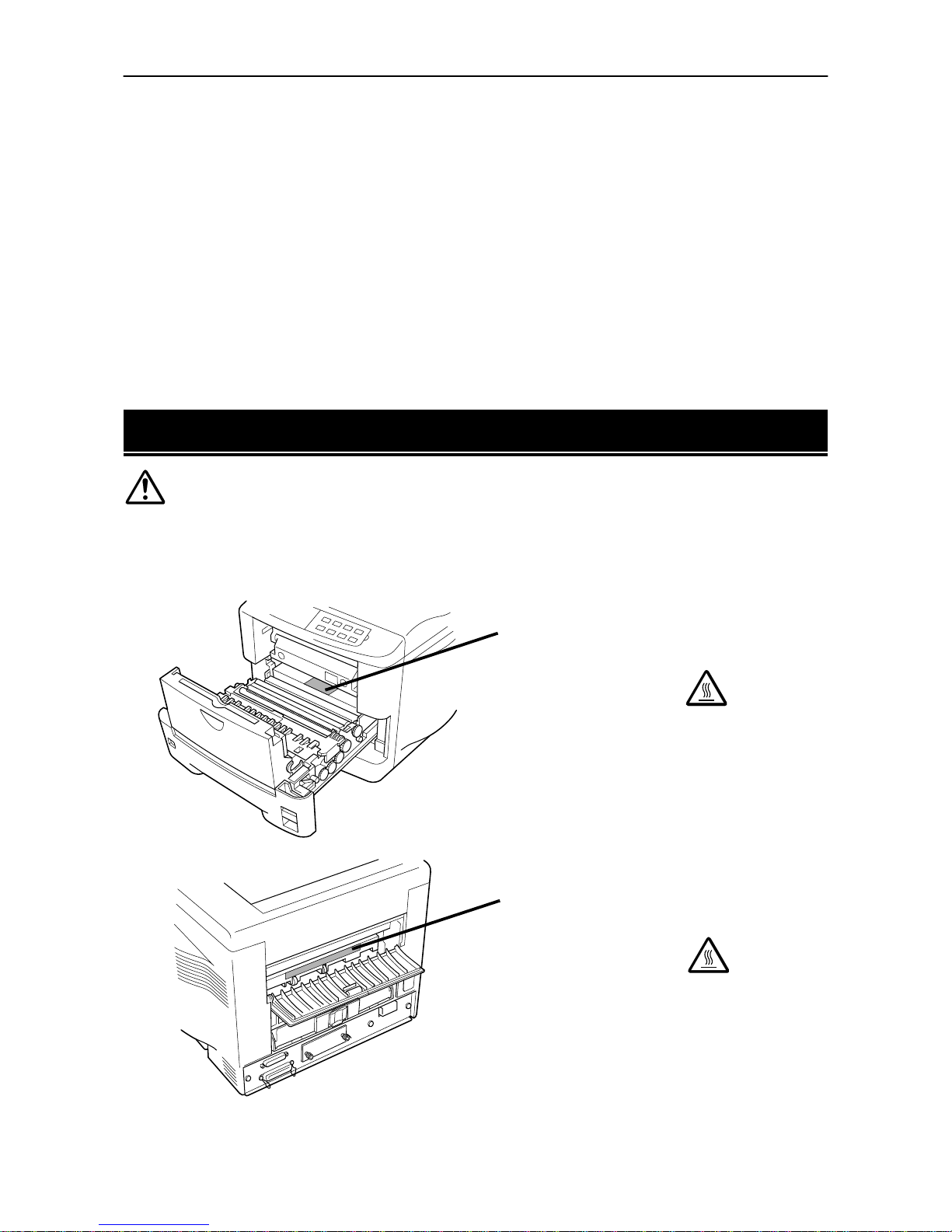
CAUTION LABELS
Caution labels have been attached to the copier at the following locations for safety
purposes. BE SUFFICIENTLY CAREFUL to avoid fire or electric shock when
removing a paper jam or when replacing toner.
Label 1
High temperature inside.
DO NOT touch parts i n this area,
because there is a danger of
getting burned.........................
Label 2
High temperature inside.
DO NOT touch parts in this area,
because there is a danger of
getting burned.........................
Page 24
1.1. Safeguards
1-2
INST ALLA TION PRECAUTIONS
■■■■
Environment
CAUTION
• Avoid placin g the printer on or in location s which
are unstable or not level. Such locations m ay
cause the printer to fal l down or fall over. This ty pe
of situation presents a danger of pers onal injury
or damage to the printer .....................................
• Avoid locat ions with humid ity or dust and dirt. If
dust or dirt becomes attached to the power plug,
clean the plug to avoid the danger of the fire or
electrical shock..................................................
• Avoid locat ions near radia tors, heaters, or other
heat sources, or loc ations near flammable items,
to avoid the dange r of fire...................................
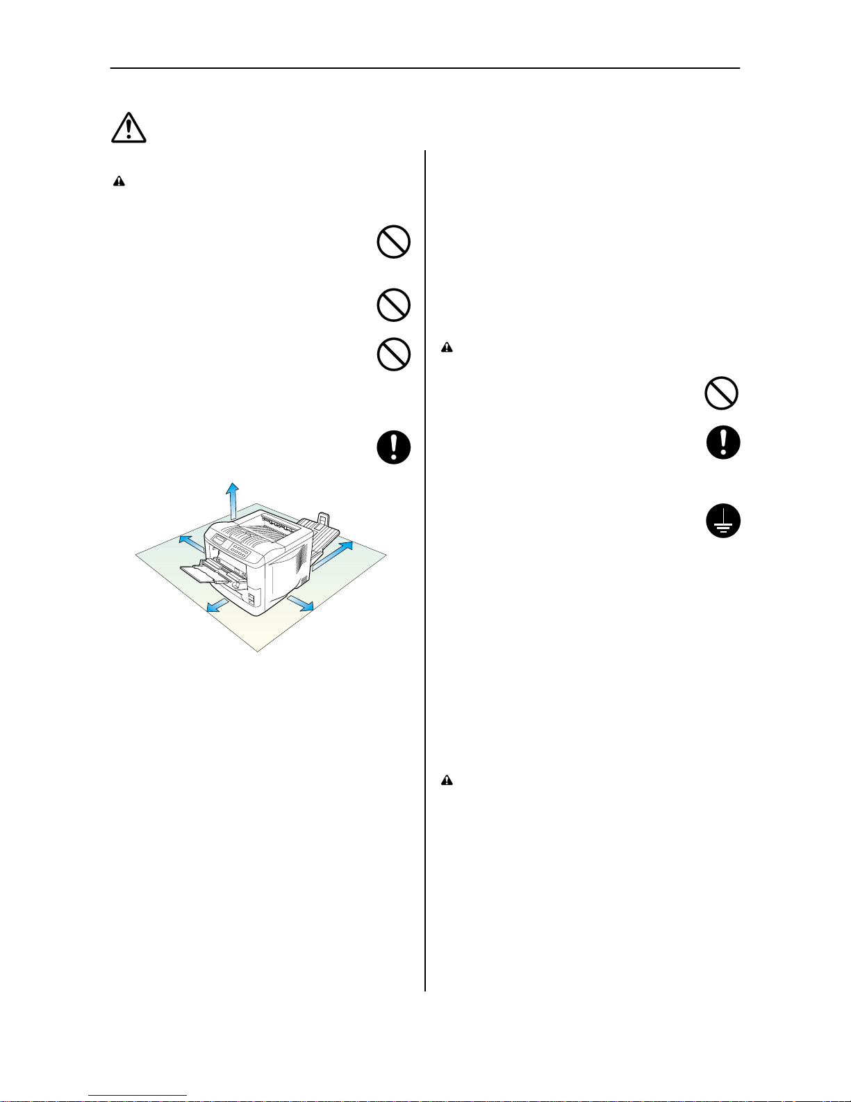
• T o keep the printer cool a nd facilitate changing of
parts and maintenance, allow access space as
shown below.
Leave adequate sp ace, especial ly around the
left, right and rea r cover, to allo w air to be properly
ventilated out of th e printer .................................
Other precautions
• Adverse environm ental conditi ons may affec t the safe
operation and performance of the prin ter. Insta ll in an airconditioned room (r ecommended room temperature:
around 20°C, humidity: arou nd 65%RH) and avoid the
following locations when selecting a site for the p rinter .
• Avoid loca tions near a wi ndow or with expo sure to
direct sunlight.
• Avoid locations with vibrations.
• Avoid loca tions with dras tic temperature fluctuations.
• Avoid locatio ns with direct exposure to hot or cold ai r.
• Avoid poorl y ventilated loc ations.
• Ammonia or other harmf ul fumes. (If you are planning
to fumigate the room , or make libe ral use of insec ticide, remove the printe r first.)
• Low air pressure, e.g., located mo re than 2000 maters
(6500 feet) above sea level.
• The printer will work bes t if it is installed in a locaion that is:
• Near the computer
If the parallel interfac e is used to connect the prin ter to
the computer , the connecting cable should be shield ed
type and not be lo nger than 3 met ers (10 feet).
• Level and well s upported
Place the printer on a steady table or desk. Do no t
place the printer on an unstable c art, stand, or ta ble.
The printer may fall, causing injury , or serious damage
to the printer .
■■■■
Power supply/Grounding the priner
WARNING
• DO NOT use a power supply with a voltage other
than that specified. Avoid multiple connections in
the same outlet. The se types of s ituations
present a danger of fi re or electrical s hock.........
• Plug the power co rd securely into the outlet. If
metallic objects come in co ntact with the prongs
on the plug, it m ay cause a fire or electric sho ck.
• Always connect the printer t o an outlet wi th a
ground connection to avoid the dan ger of fire or
electrical shock in case of an ele ctric short. If an
earth connection is not possible, contact your
service representative.......................................
Other precautions
• Connect the power plug to the cl osest outlet pos sible to
the printer .
• Near an AC wall outl et, preferably o ne that can be used
for the printer alone.
• Only use this printer under the voltage listed on the serial
No. label attached to the rear panel of the printer .
• The outlet shou ld be earthed, or an adapter sh ould be
used.
• If an extension cord is used, the total length of the po wer
cord plus extension should be 5 me ters (17 feet) or less.
■■■■
Handling of plastic bags
WARNING
• Keep the plastic bags tha t are used with the printer away
from children. The pl astic may cling t o their nose an d
mouth causing suf focation.
30 cm (12 inches)
30 cm (12 inches)
60 cm (24 inches)
25 cm (10 inches)
[20 cm (8 inches) when the face-up output tray* is not installed.]
* Optional with the DP-1400
40 cm (16
inches)
Page 25
1.1. Safeguards
1-3
PRECAUTIONS FOR USE
■■■■
Cautions when using the printer
WARNING
• DO NOT place metallic objects or containers with
water (flower vases, f lower pots, cups, etc ) on or
near the printer . This type o f situation presents a
danger of fire or electrical shock sho uld they fall
inside. ................................................................
• DO NOT remove any of the covers from the
printer as there is a danger of electrical shock
from high voltage parts insid e the printer............
• DO NOT damage, brea k or attempt to repair the
power cord. DO NOT place he avy objects on the
cord, pull it, bend it unnecessa rily or cause any
other type of damage.
These types of situations pres ent a danger of fire
or electrical shock..............................................
• NEVER attempt to repair or disassemble the
printer or its parts as there is a danger of fire, electrical shock or damage to the laser. If the laser
beam escapes, th ere is a dange r of it causing
blindness...........................................................
• If the printer becomes exessively hot, smoke
appers from the printer, there us an odd smell, or
any other abnormal situation occurs, there is a
danger of fire or electrical shock. Turn the ma in
switch OFF ( ) immediatel y, rem ove the power
plug from the outlet and contact your service rep-
resentative.........................................................
• If anything harmful (paper clips, water, other fluids, etc) falls into t he printer , turn the main switch
OFF ( ) immediately. Next, remove the power
plug from the outle t to avoid the danger of fire o r
electrical shock. Th en contact your service repre-
sentative............................................................
• When adding memo ry , AL W A YS remove the
power plug from the outle t. If this operation is performed with the power still attach ed, there is a
danger of electrical sho ck..................................
• DO NOT remove or connect the power pl ug with
wet hands, as th ere is a danger of electrical
shock.................................................................
• For safety purpose, ALWAYS rem ove the power
plug from the outlet when cleaning the main
charger. .............................................................
• AL WA YS contact your servi ce representative for
maintenance or repair of internal parts ...............
CAUTION
• DO NOT pull the power cord whe n removing it
from the outlet. If the cord is pulled, the wires may
become broken and there is a dange r of fire or
electrical shock. (ALWAYS g rasp the plug wh en
removing the power c ord from the outle t.)..........
• AL WA YS re move the power plug from the outl et
when moving th e printer . If th e cord is dama ged,
there is a danger o f fire or electrical shock. ........
• If the printer will not be used for a short period of
time (overnight, etc ), turn the main switch OFF
().
If it will not be used for an extend ed period of time
(vacations, etc), remov e the power plug from th e
outlet for safety pu rposes during the time the
printer is not in us e.............................................
• Always hold the designa ted parts only when lift-
ing or moving the p rinter ....................................
• For safety purpose, ALWA YS remove the power
plug from the outlet when performing c leaning
operations.........................................................
• If dust accumulates within the prin ter, these is a
danger of fire or oth er trouble. It is th erefore recommended that you consult w ith your service
representative is regard to cleaning of internal
parts. This is partic ularly effe ctive if acco mplished prior to seasons of high humidity. Consul t
with your service representa tive in regard to the
cost cleaning the i nternal parts of the printer ......
Other precautions
• DO NOT place heavy objects on the printer or cause other
damage to the prin ter.
• DO NOT open the front cove r, turn of f the main switch, or
pull out the power plug during printing.
• During printing, some oz one is released, but th e amount
does not cause a ny ill ef fect to one's he alth. If, howev er,
the printer is used o ver a long peri od of time in a poorly
ventilated room or when making an extremely large number of prints, the sm ell may become unpleasan t. T o maintain the appropriate en vironment for prin t work, it is
suggested that the room be prope rly ventilated.
• When lifting or mo ving the printe r , contact your s ervice
representative.
• DO NOT touch e lectrical parts , such as co nnectors or
printed circuit boards . They could be damaged by s tatic
electricity.
• DO NOT attempt to perform any op erations not explained
in this handbook.
• CAUTION: Use of controls or adjustments or performance of procedures other than thos e specified herei n
may result in hazardous radiati on exposure.
■■■■
Cautions when handling consumables
CAUTION
• Avoid inha lation, ingestion, skin or eye contact. If
ingestion occurs, dilute stomach contents thoroughly with water and seek medic al treatment. If
skin contact occurs, wash wi th soap and water. If
contact with eyes oc curs, flush th oroughly with
water and seek medical treatment.....................
• Prolonged inhalation of ecessive dusts may
cause lung dama ge. Use of this product, as
intended, does no t result in inh alation of exces -
sive dusts...................................................... ....
• Keep away from childre n...................................
• DO NOT incinerate toner and ton er containers.
Dangerous sparks may cause burn...................
Other precautions
• Always read the s afety instructions whi ch are included in
the box or printed in the contain er when handling consumables.
• Dispose of the toner or toner co ntainers in ac cordance
with Federal, State an d Local rules an d regulations.
• Store consumable in a cool, dark loc ation.
• If the printer will not be used for an extended period of
time, remove the paper from the cassette, return it to its
original package an d reseal it.
Page 26
1.2. Unpacking and Inspection
1-4
1.2. Unpacking and Inspection
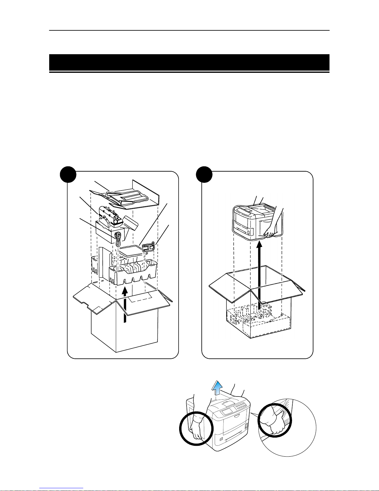
The printer is packed as shown below. Unpack the printer following diagrams 1 and 2 on the next page. While
unpacking it, check that the listed parts are all accounted for.
Examine the package for any signs of damage that may have been caused during transportation. If the carton is found to be badly damaged, leave the carton unopened and immediately notify the dealer from whom
you purchased the printer.
Save the box and other packing materials in case you have to repack the printer for transportation at a later date.
List of Shipped Components
❒
(A) Face-up output tray (DP-1800 only)
❒
(B) Toner container and Waste Toner Bottle (Box for the developer unit)
❒
(C) Power cord
❒
(D) User's Manual and CD-ROM, including the printer drivers
❒
(E) Paper stopper for Face-up out tray (DP-1800 only)
To remove the printer from the box, grasp the handholds on either side of the printer. Lift the printer from
the carton as shown below.
☛
!
Always use these handholds whenever you lift or move the printer.
!
The handhold on the right side of the
printer doubles as the memory card
slot. Be sure to remove the memory
card first, if inserted, before lifting or
moving the printer.
2
Printer
(D)
(C)
1
(A)
(B)
(E)
Page 27
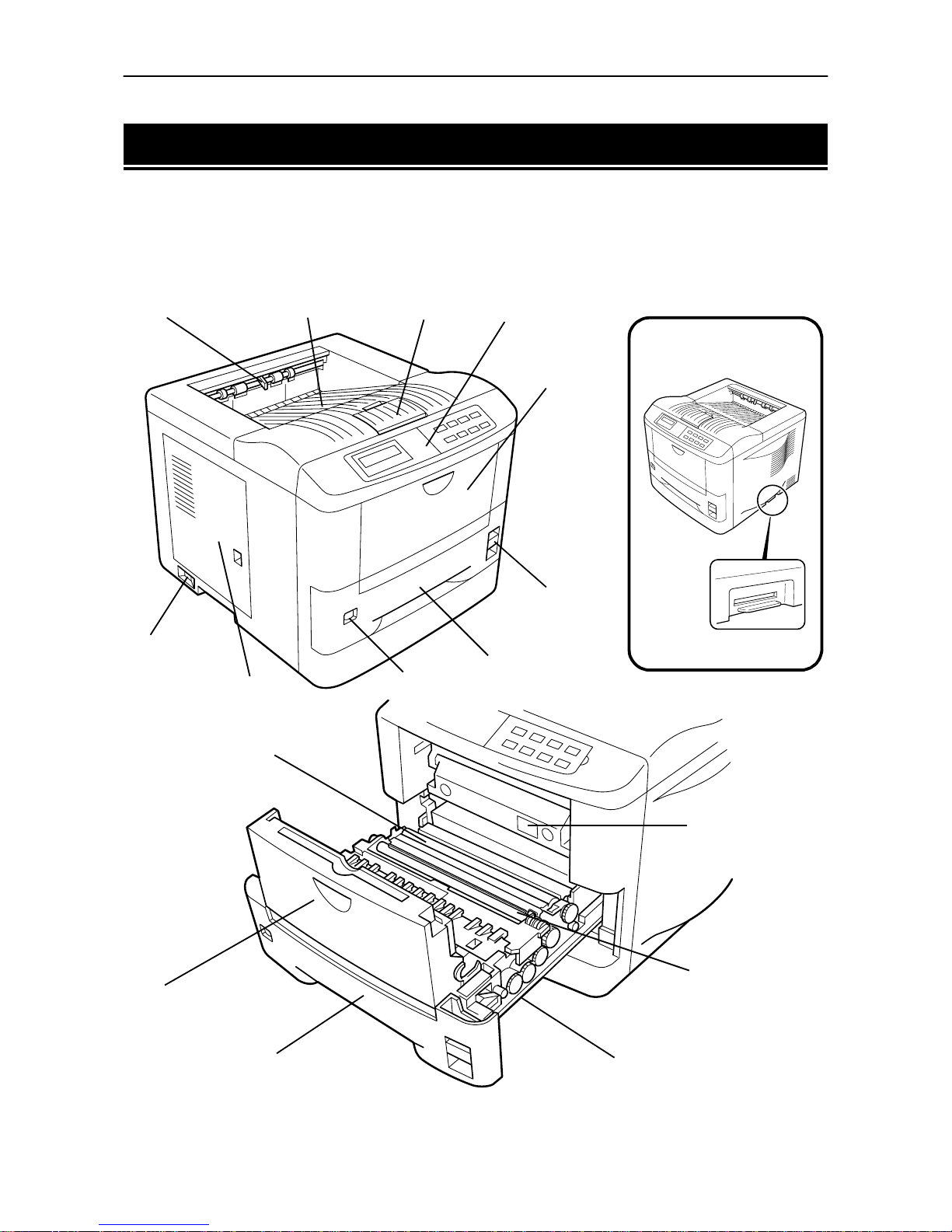
1.3. Names of Parts
1-5
1.3. Names of Parts
This section takes you on a guided tour of the printer, pointing out its major parts. The part names introduced
here will be used throughout this manual.
Front View
Paper Full Sensor
(Model DP-1800 only)
Face-down
Output Tray
Paper Stopper Control Panel
MP
(Multi-Purpose) Tray
Paper Feed
Unit Release
Lever
Paper Cassette
Side Cover
Power Switch
Memory Card Slot
Transfer Roller
MP Tray
Paper Cassette Paper Feed Unit
Registration Roller
Size Window
Option Paper Feeder
Connector*
Page 28
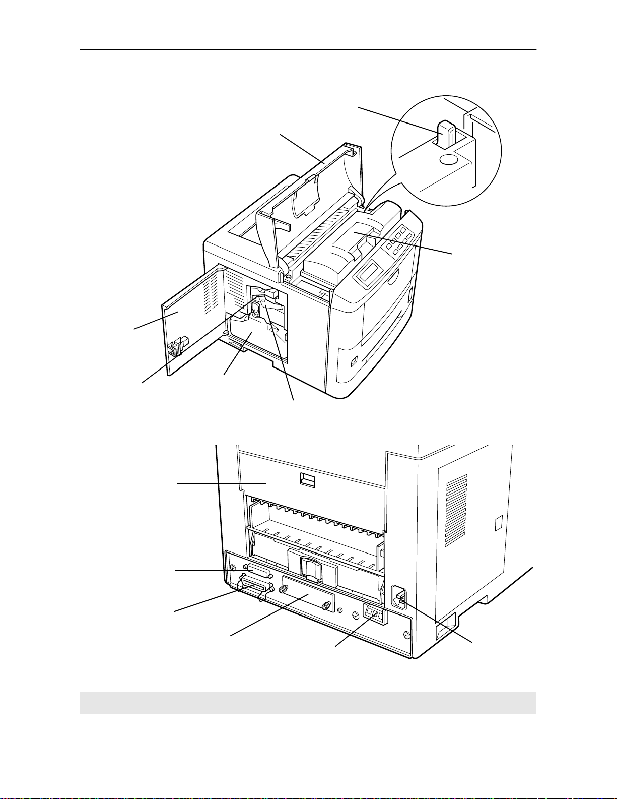
1.3. Names of Parts
1-6
Interior View
Rear View
*: To protect the printer against static discharge, the connector must be covered with the supplied protective cap
when not in use.
T
oner Container Release
Lever (Green)
To p Co ve r
Toner Container
Side Cover
Cleaner Knob (Green)
Waste Toner Bottle
Main Charger Unit
Rear Cover
Serial Interface
(RS-232C/RS-422A)
Connector
Parallel Interface Connector
Option Interface Slot Cover
Option Paper
Handler/Stacker Connector*
Power Cord
Receptacle
Page 29

1.4. Setting Up and Interfacing
1-7
1.4. Setting Up and Interfacing
Before you can use the printer for the first time, you must set up the printer by installing the printer components and interfacing with the computer. The steps to be followed in setting up are:
1.
Open the top cover.
2.
Install the toner container.
3.
Close the top cover.
4.
Install the waste toner bottle.
5.
Adjusting the paper guides in the cassette and adding paper.
6.
Open the paper stopper on the face-down output tray.
7.
Install the face-up output tray (if required).
8.
Connect the printer to the computer.
9.
Attach the power cord.
10.
Print a status page.
11.
Test the interface with the computer.
12.
Set the emulation mode.
13.
Install the printer driver.
Page 30
1.4. Setting Up and Interfacing
1-8
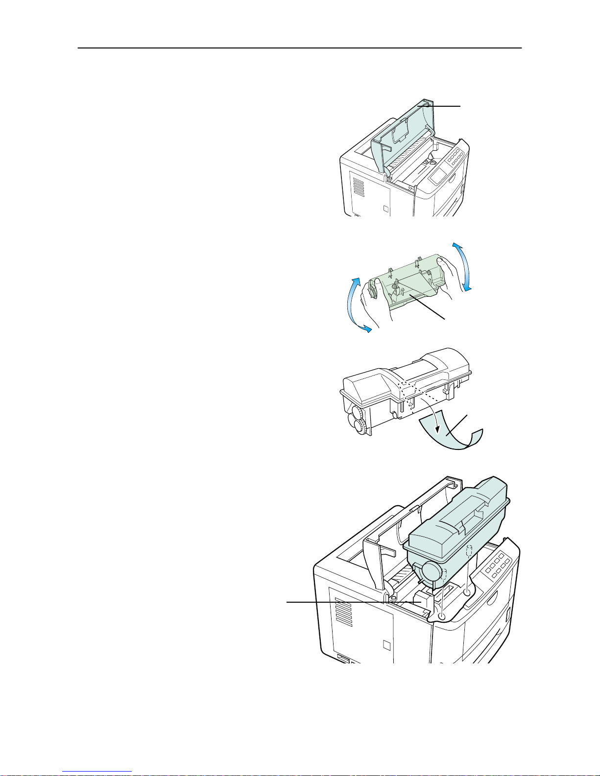
1—Open the top cover
1.
Remove the packing tape from the printer.
2.
Open the printer top cover all the way.
2—Install the toner container
1.
Take the toner container from the toner kit.
2.
With the label side down, thoroughly shake the
toner container (in the direction of the arrow) ten
times or more to loosen and mix the toner inside.
3.
The bottom of the toner container is sealed with a
sealing strip. Peel off the seal on the toner container
and carefully pull off and dispose of the sealing
strip.
☛
Be sure to peel the seal off the toner container
before the toner container is fitted into the developer unit.
4.
Install the toner container on the developer
as show in the diagram.
To p Co ve r
Toner Container
Sealing strip
Developer Unit
Page 31
1.4. Setting Up and Interfacing
1-9
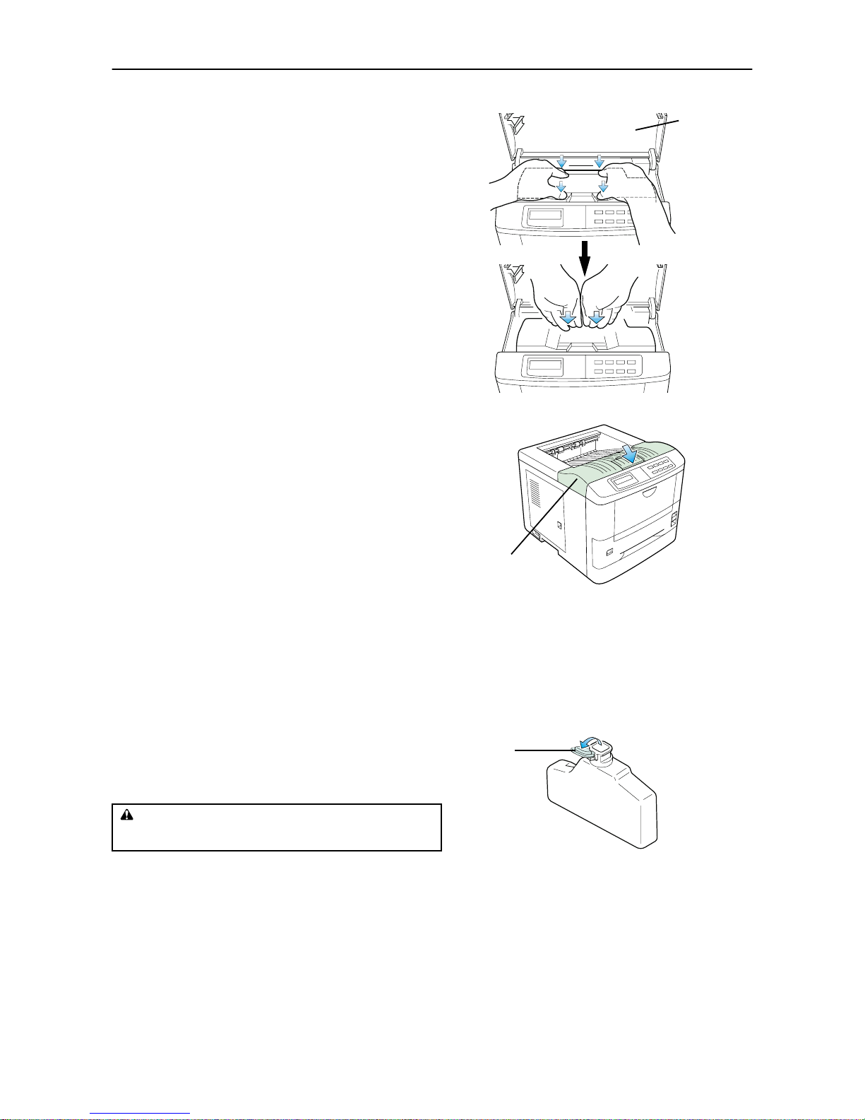
5.
When the toner container is installed correctly on
the developer, push the top of the container unit
("PUSH HERE") until it locks in.
☛
Make sure that the toner container is properly
locked in the printer.
3—Close the top cover
Close the top cover by pressing the arrowed part in this
diagram.
4—Install the waste toner bottle
The waste toner bottle is in the toner kit supplied with the printer. The waste toner bottle must be installed
in the printer.
Install the waste toner bottle in the printer as follows.
1.
Take the waste toner bottle from the toner kit supplied.
☛
Do not cap the waste toner bottle.
CAUTION
Do not incinerate to ner and toner co ntainers. Dan gerous
sparks may caus e burn.
Top Co ver
To p Co ver
Cap
Waste Toner
Bottle
Page 32
1.4. Setting Up and Interfacing
1-10
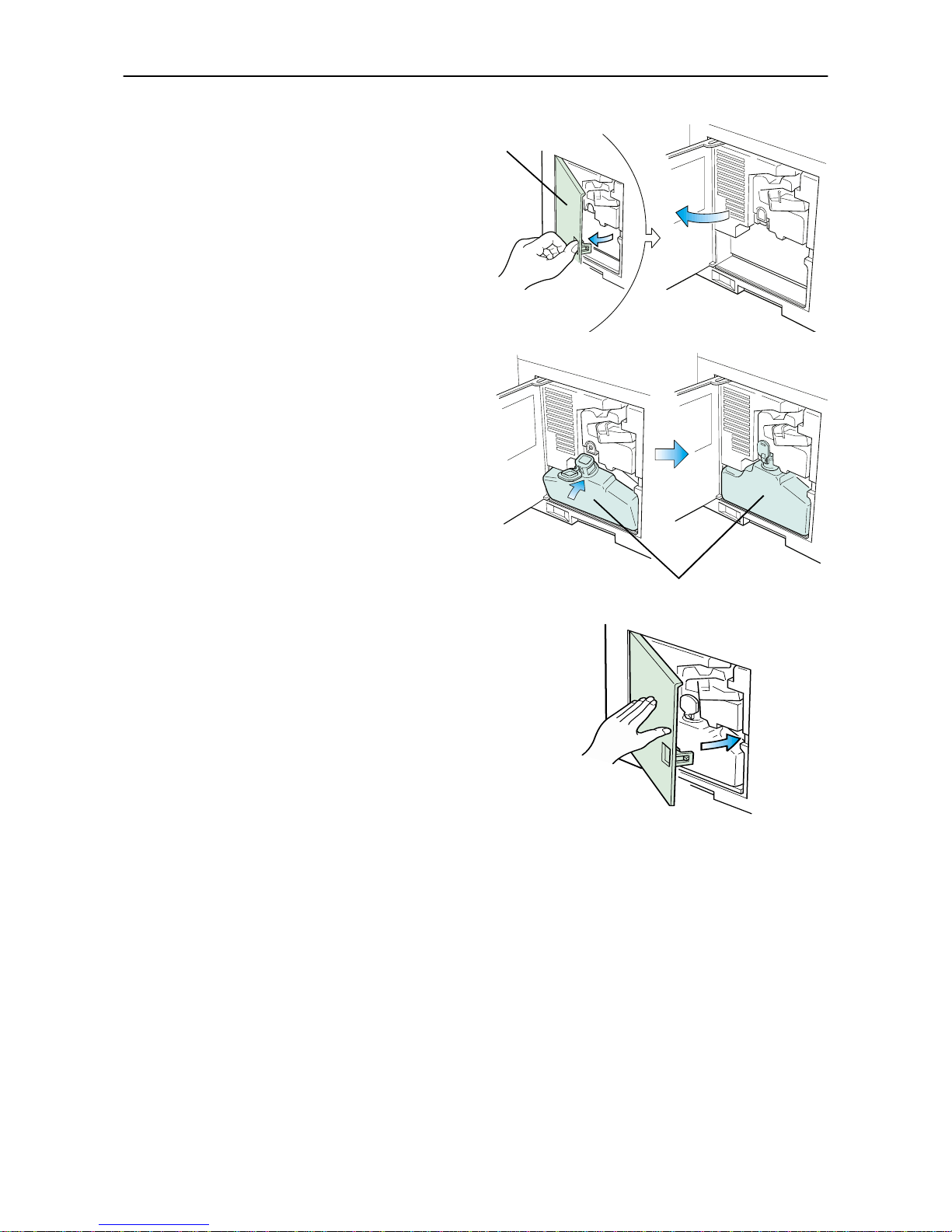
2.
Open the side cover on the left side of the printer.
3.
Insert the waste toner bottle with the bottle tilted
slightly towards you as shown in the figure.
4.
Ensuring that it is correctly inserted, close the side
cover.
Side Cover
Waste Toner Bottle
Page 33
1.4. Setting Up and Interfacing
1-11
5—Adjusting the paper guides in the cassette and adding paper
The paper cassette provided with the printer can accommodate paper sizes from A5 to legal, by adjusting the
position of the paper guides and the paper stopper. Paper sizes that are not standard sizes (custom sizes) but
within the size limitations can also be loaded into the cassette. When loading custom sizes into the cassette,
the size must be input into the printer on the control panel. (Refer to 2.7. Setting Custom Sizes) Standard
size paper settings are indicated as fixed positions in the cassette.
☛
!
Before adding paper, remove the paper cassette all the way from the printer.
!
Read the paper manufacturer's instructions concerning handling of the paper.
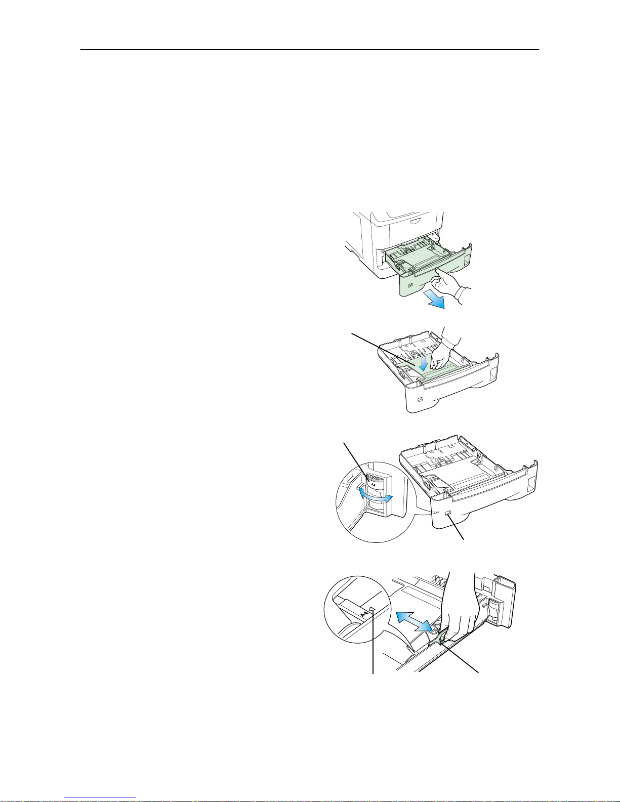
1.
Remove the paper cassette from the printer, and
place it on a flat, stable surface.
2.
Push the bottom plate down until it locks.
3.
Turn the paper size dial so that the size of the paper
you are going to use appears in the paper size window.
☛
When the paper size dial is set to "Custom" the
paper size must be set into the printer on the control panel. See
2-7 Setting Custom Sizes
for the
setting procedure.
4.
Adjust the pa per guide and paper stopper positi ons.
Move the paper guides while lifting the green latch
on the right. Set the triangular markings on the
guides to the size of paper that you are to use as
indicated.
Paper Cassette
Bott
om Plate
P
aper Size Dia
l
Paper Size Win-
Paper Guide
Triangle Mark
Page 34
1.4. Setting Up and Interfacing
1-12
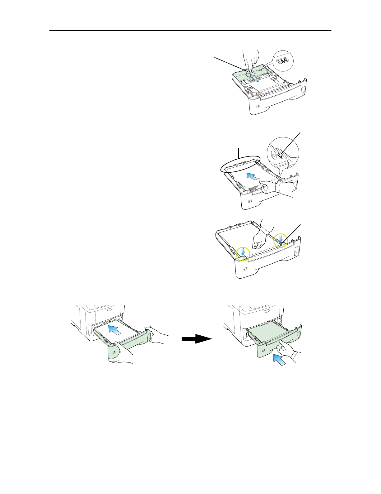
Move the paper stopper while pushing on the green
button at the back. Set the paper stopper to the size
of paper that you are to use as indicated in the small
windows on the floor of the cassette.
When using custom size paper, move the paper
guides and paper stopper all the way out, insert the
paper, and then adjust the paper guides and paper
s t o p p e r t o s u i t . A d j u s t t he m s o t h a t t h e y a re i n l i g ht
contact with the paper.
5.
Tap the edges of the paper to align the sheets neatly.
Set the paper in the cassette as shown. The side of
paper that faces downward in the cassette is the
one on which printing is done.
Do not load paper into the cassette higher than the
limitation mark on the right (The cassette should
hold approximately 250 sheets of paper with a 0.1
mm thickness.)
6.
Set the stack of paper so that it is under the clips as
shown.
7.
Hold the cassette as shown in the illustration and
insert the paper cassette into the printer cassette
slot. Push it straight in as far as it will go.
☛
If the paper size dial on the cassette is not set to
match the size of paper inserted, a paper jam may
result.
Paper Stopper
Limitation mark
When loading the
paper, make sure the
leading edge of paper
is not bent in any w ay.
Clip
Page 35
1.4. Setting Up and Interfacing
1-13
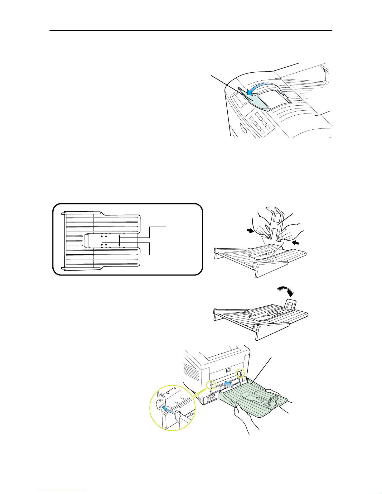
6—Open the paper stopper on the face-down output tray
Open the paper stopper as shown right.
7—Install the face-up output tray (if required)
☛
This face-up output tray is a separate option (FT-200) with the DP-1400.
If you want the printed pages stacked face-up (in reverse order), mount the face-up output tray as follows.
Depending on the size of the paper you use, mount the paper stopper on the face-up output tray as shown
below.
Paper Stopper
Legal Size
A4 Size
Letter Size
Paper Stopper
Face-up Output
Tray
Page 36
1.4. Setting Up and Interfacing
1-14
8—Connect the printer to the computer
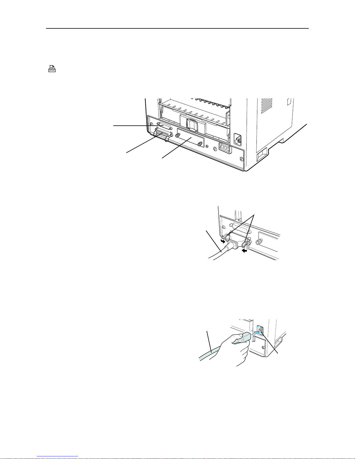
The printer has two computer cable connectors and a slot for installing an option interface. The one marked
" " is for a parallel (Centronics standard) interface. The one marked "IOIOI" is for a serial (RS-232C/
RS-422A) interface. You may use whichever is convenient for your computer, with the option interface, if you
have already have one installed. All interface connectors can be used simultaneously with different computers.
☛
Only connect or disconnect cables to the connectors while the printer and computer power are
switched off.
Parallel interface
Plug one end of the cable into the connector marked Parallel on the printer. Close the clips on both sides to hold
it in place.
Plug the other end into a parallel (Centronics) interface
connector on your computer. This connector is usually
marked PRINTER.
See Appendix C for more details about the parallel
interface.
Serial interface
The serial interface of this printer is set to RS-232C mode before leaving the factory, but can also be set to RS422A mode to suit your operating environment. Follow the instructions in Appendix C.
9—Attach the power cord
1.
Check that the power switch is off.
2.
Plug one end of the power cord into the receptacle at
the back of the printer.
3.
Plug the other end into the wall outlet.
Serial (RS-232C/RS422A) Interface Connector
Parallel Interface Connector
Option Interface
Slot Cover
Printer Cable
Clips
Rear Panel
Power Cord
Receptacle
Power Cord
Page 37

1.4. Setting Up and Interfacing
1-15
10—Print a status page
Test that the printer works by printing out a status page as follows.
1.
Switch on the printer's power. The message display should indicate Self test.
☛
When the printer is first switched on after installation, there will be a delay of several minutes
(approx. 6 to 7 minutes) before the printer gets ready to print. During this period, the message display shows
Please wait
.
2.
Wait until the ON LINE indicator is also lit and the message display indicates Ready.
3.
Press the STATUS key. The printer should print a page listing the positions of margins, memory allocation, and other information.
A sample status printout is shown in Chapter 2.
11—Test the interface with the computer
Test that the printer and computer are correctly connected. If you have connected the printer and computer
with a parallel interface cable, follow the procedure below.
1.
Check that the printer's message display indicates Ready and that the ON LINE indicator is ON.
2.
Boot the computer in DOS mode, or set the computer to DOS (prompt) mode.
3.
At the DOS prompt, type the following.
ECHO !R! STAT; EXIT;>PRN
If the printer prints a status page, the computer and printer are connected correctly. For details on the status
page, refer to Chapter 2.
If you do not get this result, check that the cable is securely plugged in at both ends, and repeat the test. If
you still do not get the right result, you may have a defective or improperly-wired cable. Try using a different
cable.
12—Set the emulation mode
The printer emulates the operation of five other printers. It is factory-set to emulate the PCL 6 at power-up.
If you primarily use software that supports PCL 6, or that supports the Kyocera printer itself, the factory
setting is the one you want. If you primarily use software that supports another printer, it is convenient to
change the printer's power-up emulation mode.
The emulation mode can be changed from the printer control panel. To change the emulation mode, refer to
the Mode Select Menu diagram on the last page of this manual.
CAUTION
If the printer will not be u sed for a short period of time (o vernight, etc), turn the main s witch OFF ( ). If it will not be used for
an extended pe riod of time (va cations, etc), rem ove the power plug from the ou tlet for safety purposes during th e time the
printer is not in use.
Page 38

1.4. Setting Up and Interfacing
1-16
13—Install the printer driver
Printer drivers are provided for using the printer with Windows 95, Windows 98, Windows NT3.51, or Windows NT4.0. Use the Mita Printer Library CD-ROM supplied with the printer. To install the printer driver,
proceed as follows. Reference to the Windows manual is also recommended.
Page 39
1.4. Setting Up and Interfacing
1-17
Windows 95/Windows 98
1.
Insert the supplied CD-ROM (Mita Printer Library) into the CD-ROM drive of the computer.
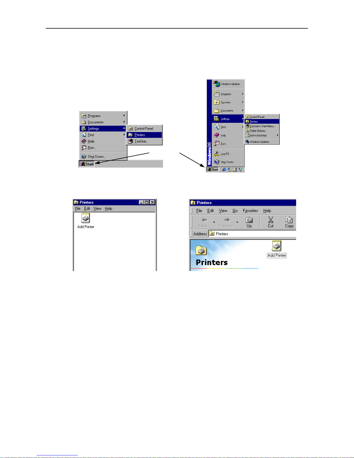
2.
Click on Start with the mouse on the Windows95/98 Task Bar, and align the cursor with Settings. Click
on Printers among the items displayed.
3.
The printer folder will open. Double click on Add printer.
4.
The Printer Wizard screen will appear. Click on Next >.
5.
A screen for selecting the printer to be connected will appear. Select the most appropriate printer and
click on Next.
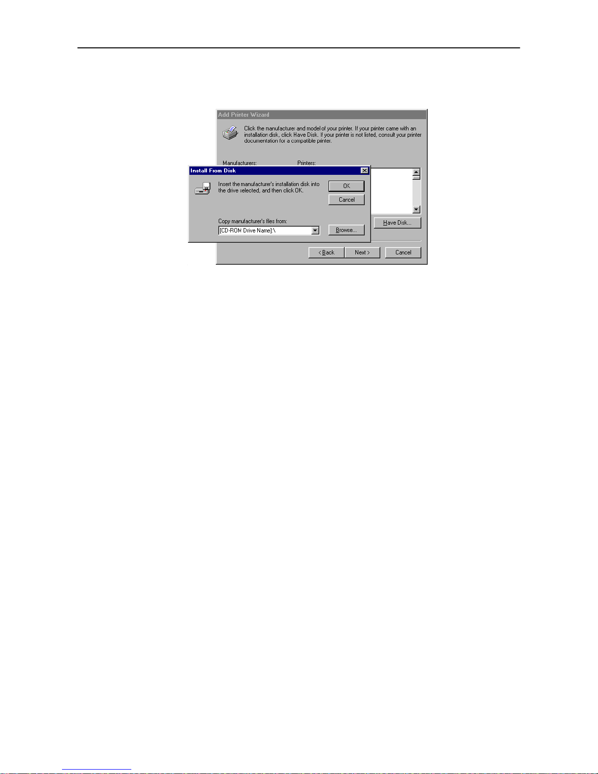
6.
Next, Click the manufacturer and model of your printer.... screen will appear. At this point, select Have
Disk ... located at the lower right. (See the figure for Step 7.)
7.
A screen for installing from floppy disk will appear. Copy manufacture's files from inside the box, or
input one of the following directories:
(Standard PCLXL driver)
[CD-ROM Drive Name]:\drivers\[Language]\pcl\Win 95 (or Win 98)\enhanced\Dp1400 (or
Dp1800)
(Microsoft Mini driver)
[CD-ROM Drive Name]:\drivers\[Language]\pcl\Win 95 (or Win 98)\uni
Start button
Windows 95 Windows 98
Windows 95 Windows 98
Page 40
1.4. Setting Up and Interfacing
1-18
(Standard KPDL driver)
[CD-ROM Drive Name]:\drivers\[Language]\Kpdl\Win 95 (or Win 98)
8.
Select Mita DP-1400 or Mita DP-1800 click on Next >, and follow the on-screen instructions to install.
Once the driver has been properly installed, the printer icon will be added to the printers folder.
☛
When printing under Windows 95/98, be sure to set the emulation of this printer to PCL 6 (default
setting).
Page 41
1.5. MP (Multi-Purpose) Tray Feeding
1-19
1.5. MP (Multi-Purpose) Tray Feeding
The MP tray is incorporated on the front of the printer. It can be used in one of two modes: first mode or cassette mode. The MP tray can hold about 100 sheets of paper (A4 size, 0.1 mm thickness).
If you set a full number of sheets for sizes bigger than A4, it could cause a paper jam. In this case, set a lower
number of sheets than the full amount, confirm that there will be no paper jams and then commence printing.
First Mode (Automatic Manual Feeding)
The printer automatically feeds any paper placed on the MP tray even if another paper source is selected.
After all paper in the MP tray is printed, paper will be fed from the paper source originally set. (This is the
factory set default.)
Cassette Mode
The cassette mode provides faster printing speed than the first mode. Approximately 100 sheets of paper
can be continuously fed in this mode.
Duplex Printing from the MP tray
In first mode, be sure to set the MP tray to the same paper size and paper type as set for the current cassette.
If the paper size or type differs, a paper jam may result. Also note that it is not possible to select the MP tray
as the current cassette and perform duplex printing. We therefore recommend that duplex printing be performed from the paper cassette. An optional duplexer (AD-34) is required to perform duplex printing.
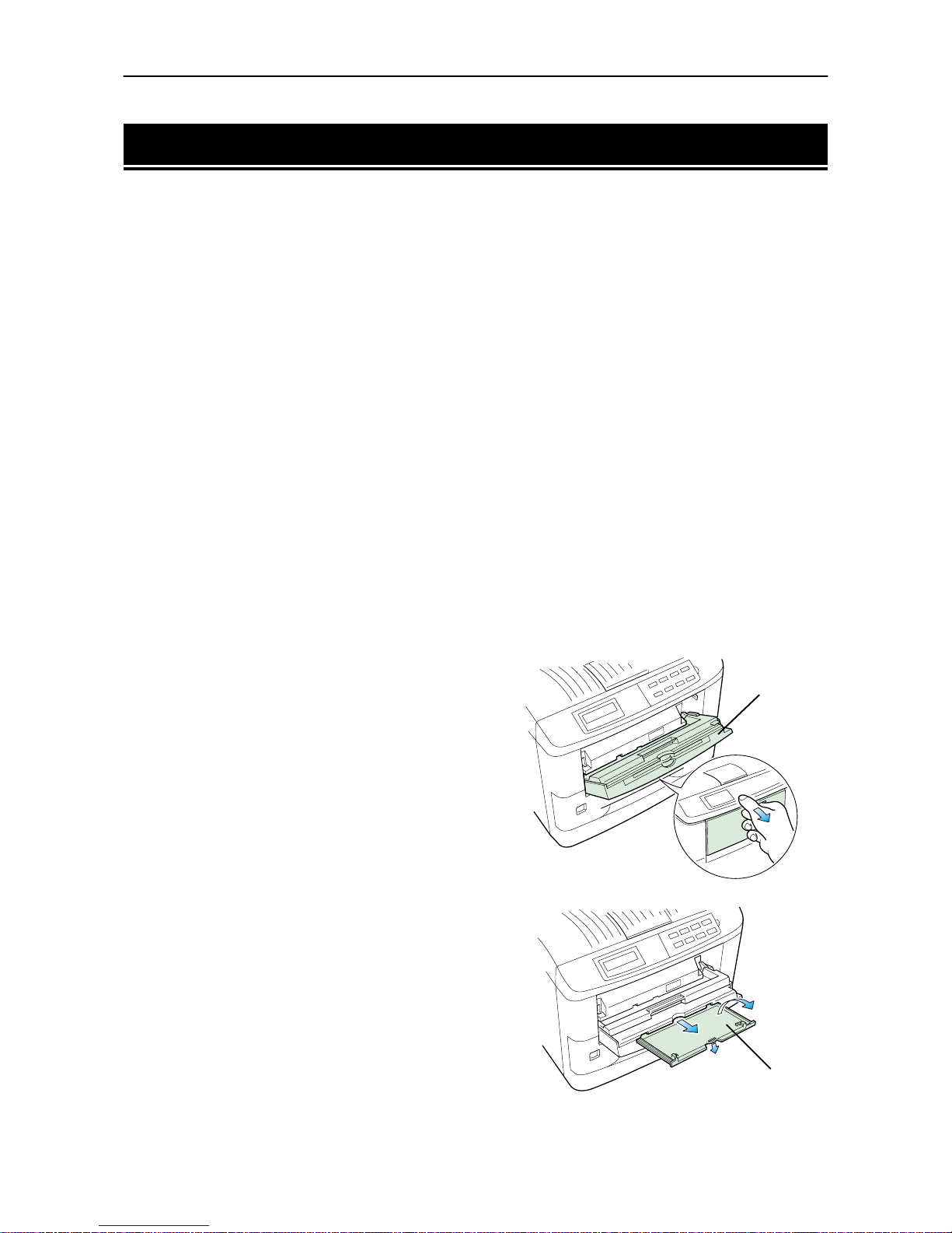
Selecting the MP Tray
1.
Taking hold of the front of the printer as shown in
the figure, open the M P tray by pulling towards you.
2.
Withdraw the sub tray as shown in the diagram.
MP Tray
Sub Tray
Page 42

1.5. MP (Multi-Purpose) Tray Feeding
1-20
3.
Raise the paper prote ctor bar until it locks in the up
position. Then adjust the paper guides to the size of
the paper being fed.
4.
Check that the message Ready is displayed in the printer's message display, and that the ON LINE
indicator is lit.
5.
Set the paper source to the multi-purpose tray by pressing the FEED key until the message display indicates MP tray. The multi-purpose tray indicator on the control panel will flash, and Add paper
will be displayed.
6.
Press the MODE key. Then use + or – keys to display Paper handling >.
7.
Press the (Form Feed) key to display >MP tray size or > MP tray type, then press the ENTER
key so you can set the paper size or type to be fed from the MP tray. See Mode Select Menu at the end of
this manual.
The following pages explain the use of the MP tray in the Cassette Mode and First Mode.
First Mode (Automatic Manual Feeding)
The printer automatically feeds the paper placed on the MP tray regardless of the current paper source selection. To use the first mode (automatic manual feeding mode), simply place a sheet of paper on the MP tray
in the same manner as above, even while the printer is presently feeding the paper in the printer's cassette.
1.
Press the MODE key. Then use + or – keys to display Paper handling >.
2.
Press the (Form Feed) key to display >MP tray mode.
3.
After pressing the ENTER key, the mode display is changed by pressing the + and – keys. Display First
and then press the ENTER key.
>MP tray mode
First
4.
Press the EXIT key.
☛
The printer will not switch to light the MP tray indicator while the paper is fed manually using the
automatic manual feeding mode.
Paper Guides
Protector Bar
Page 43
1.5. MP (Multi-Purpose) Tray Feeding
1-21
Cassette Mode
1.
Press the MODE key to display Paper handling >.
2.
Press the (Form Feed) key to display >MP tray mode.
3.
After pressing the ENTER key, the mode display is changed by pressing the + and – keys. Display
Cassette and then press the ENTER key.
>MP tray mode
Cassette
4.
Press the EXIT key.
5.
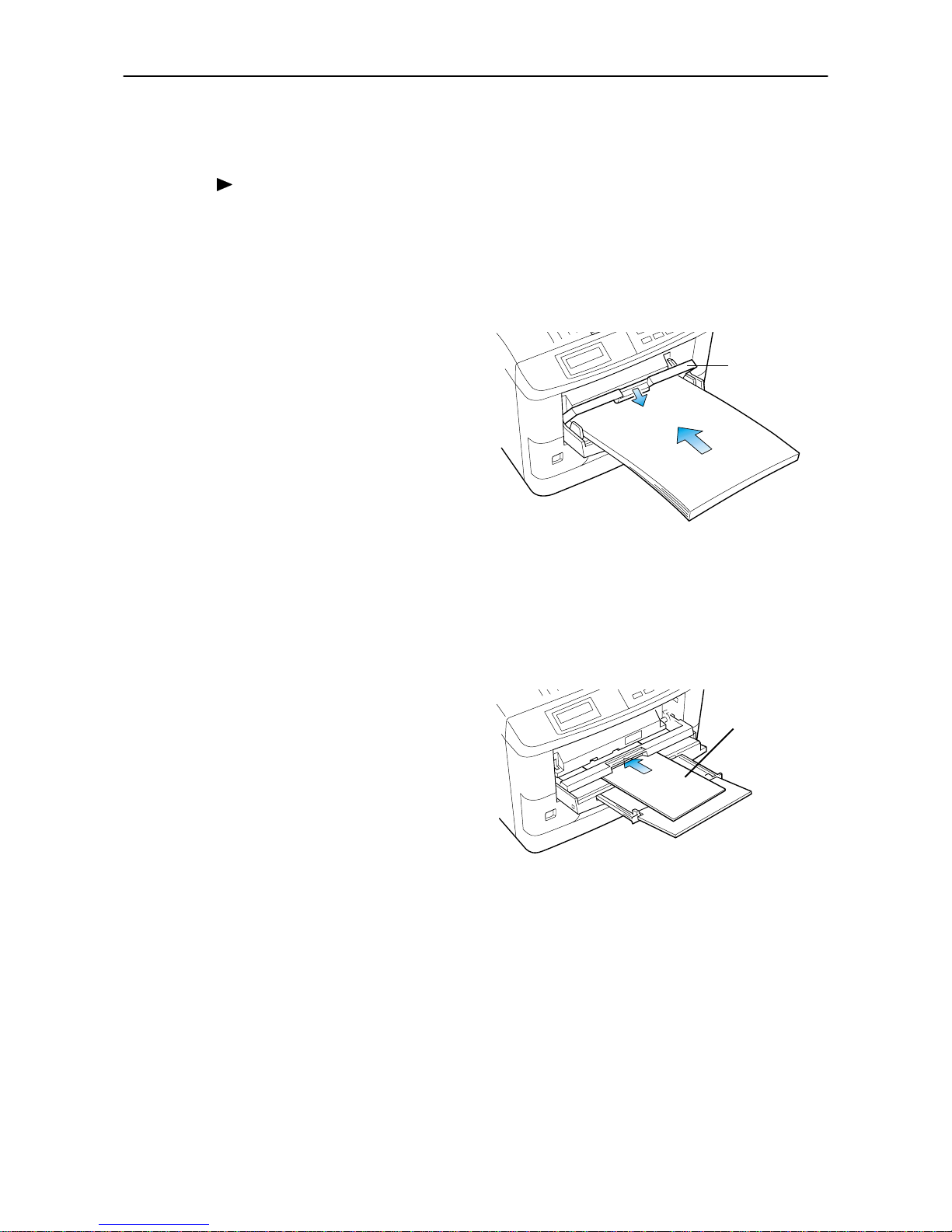
Insert the paper so that it is aligned straight in the
tray. About 100 sheets (0.1 mm thickness) can be
inserted at one time.
Ready appears on the message display.
6.
Carefully lower the protector bar, and the paper will be correctly set in the MP tray.
Feeding Envelopes
Envelopes should be fed face up, right side first, as shown below. From the MODE SELECT menu, set the
printer to print in landscape page orientation.
☛
To avoid trouble, we recommend that envelopes
are delivered face-up. Use the
STACK
key on the
printer control panel to select the face-up tray.
Not all envelopes print well. See Appendix B for details
on suitable types of envelopes.
See page 2-3 for the envelope sizes that can be set.
Protector Bar
Envelope
Page 44
1.6. Memory Card
1-22
1.6. Memory Card
A memory card is a microchip card containing, for example, nonresident fonts and/or macros, forms, etc. The
printer reads the contents of the card into its internal memory when power is switched on. The presence of
this data in the printer memory can be confirmed on the status printout.
☛
The maximum card capacity that can be used is 32 Megabytes. The type of the memory card to be
used must be of either flash memory card (+5V type) or SRAM-type and conform to the PCMCIA 2.1
(JEIDA 4.2) standards. Please use memory cards recommended by us.
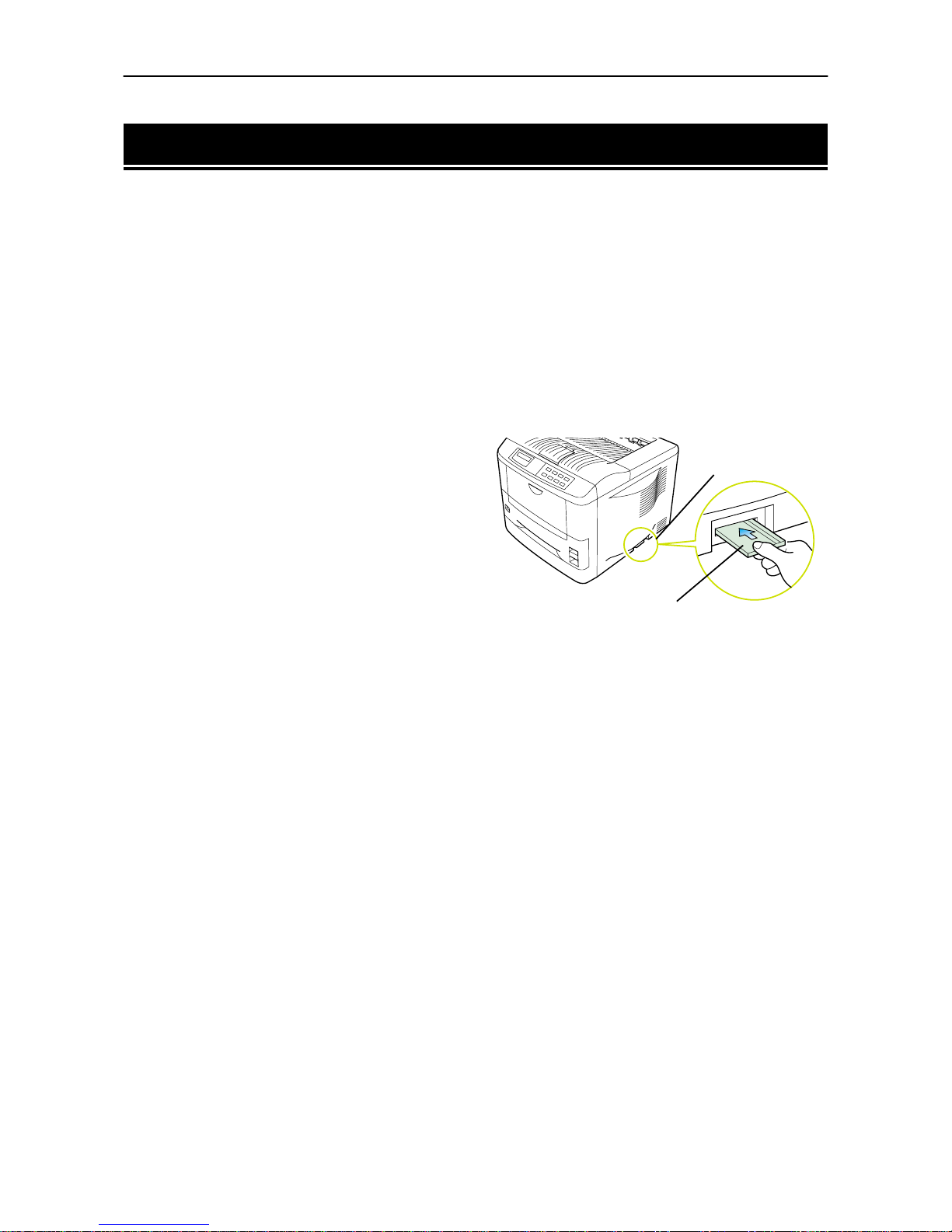
The memory card slot is located at the bottom right of the printer.
To insert and use a memory card:
1.
Switch printer power off.
☛
Do not insert or remove a memory card while power is on. If the memory card is removed while the
printer is on, damage could result in the printer's electronics or the memory card.
2.
Insert the memory card in the slot. Insert it face up,
connector end first. Push it in all the way.
3.
Switch printer power on. The printer reads the contents of the memory card during its power-up
sequence. The information (nonresident fonts, etc.) on the memory card is now available for use.
If the memory card information is deleted from the printer's memory during the printing process, it can be
reread by using the mode selection function explained on the last page in this manual.
To Remove the Memory Card:
1.
Switch the power off.
2.
Remove the memory card from the slot.
Handling Memory Cards
Memory cards contain sensitive electronic circuits. Treat them with appropriate care.
❒
Memory cards are sensitive to electrostatic discharge. Please discharge yourself before touching a
memory card.
❒
Never attempt to force a memory card into its slot.
❒
Never bend a memory card.
❒
Avoid impact. Do not drop a memory card.
❒
Do not touch the terminals of the memory card.
❒
Do not spill water or other liquids on a memory card.
❒
Keep memory cards away from naked flames and other sources of heat.
❒
Do not leave memory cards lying in direct sunlight.
For details regarding the use of the memory card, refer to 2.6. Operating a Memory Card in this manual.
Memory Card Slot
[PC CARD (MEM-
Memory Card
Page 45
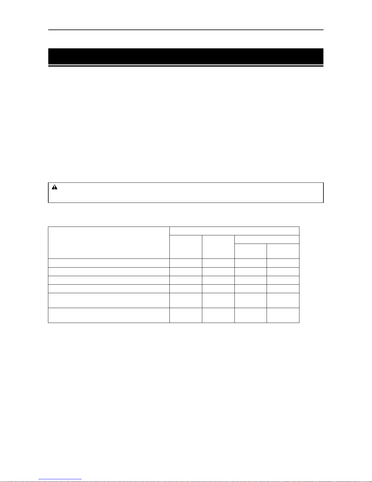
1.7. Memory Expansion Installation
1-23
1.7. Memory Expansion Installation
In this section is explained how to expand the printer's memory. Expanded printer memory enables you to
print more complex pages, download more fonts, and define more macros.
It begins by explaining how to remove the main circuit board from the printer, and explains how to install a
SIMM (single in-line memory module) on the main circuit board.
The DP-1400 comes supplied with 8 MB of memory installed, and likewise the DP-1800 comes with 16 MB
of memory supplied. Two slots are provided for expanding the memory in your printer so that more complex
printing can be done, as well as increasing the printing speed. By installing optional memory cards into your
printer, the memory in the DP-1400 can be increased to a maximum of 72 MB, and the DP-1800 can be
increased to a maximum of 64 MB.
☛
!
A 16 MB SIMM is installed in one of the SIMM sockets in the DP-1800, so in order to increase the
memory to the maximum 64 MB this SIMM must be changed.
!
The expansion memory should be installed only by an authorized dealer or an certified technician. We shall not be liable for damage due to improper installation of the expansion memory.
The minimum memory requirements for the printer with various options installed are listed in the table
below. Please refer to this table when expanding the printer's memory.
Removing the Main Circuit Board
The main circuit board of the printer is equipped with two sockets for memory expansion. Expansion memory is available in the form of a SIMM.
☛
The following instructions are intended for the technician only.
Notes on Handling the Main Circuit Board and SIMM
Protect the electronics by taking these precautions:
❒
Before touching the main circuit board, touch a water pipe or other large metal object to discharge
yourself of static electricity. While doing the work, it is recommended that you wear an antistatic
wrist strap.
❒
Touch the main circuit board and SIMM only by the edges.
WARNING
When adding memo ry , AL W A YS remove the power plug from the outlet. If this operati on is performed w ith the power st ill
attached, there is a danger of electrical shock.
Printing condition
Resolution
300 dpi 600 dpi
1200 dpi
Fast m o d e
Fine
mode
PCL 6, duplex mode = None 8 MB 8 MB 8 MB 8 MB
PCL 6, duplex mode = On 8 MB 8 MB 8 MB 12 MB
KPDL, duplex mode = None 8 MB 8 MB 8 MB 8 MB
KPDL, duplex mode = On 8 MB 8 MB 12 MB 12 MB
PCL 6/KPDL resource protection,
duplex mode = None
– 10 MB 10 MB 10 MB
PCL 6/KPDL, resource protection,
duplex mode = On
– 14 MB 14 MB 14 MB
Page 46
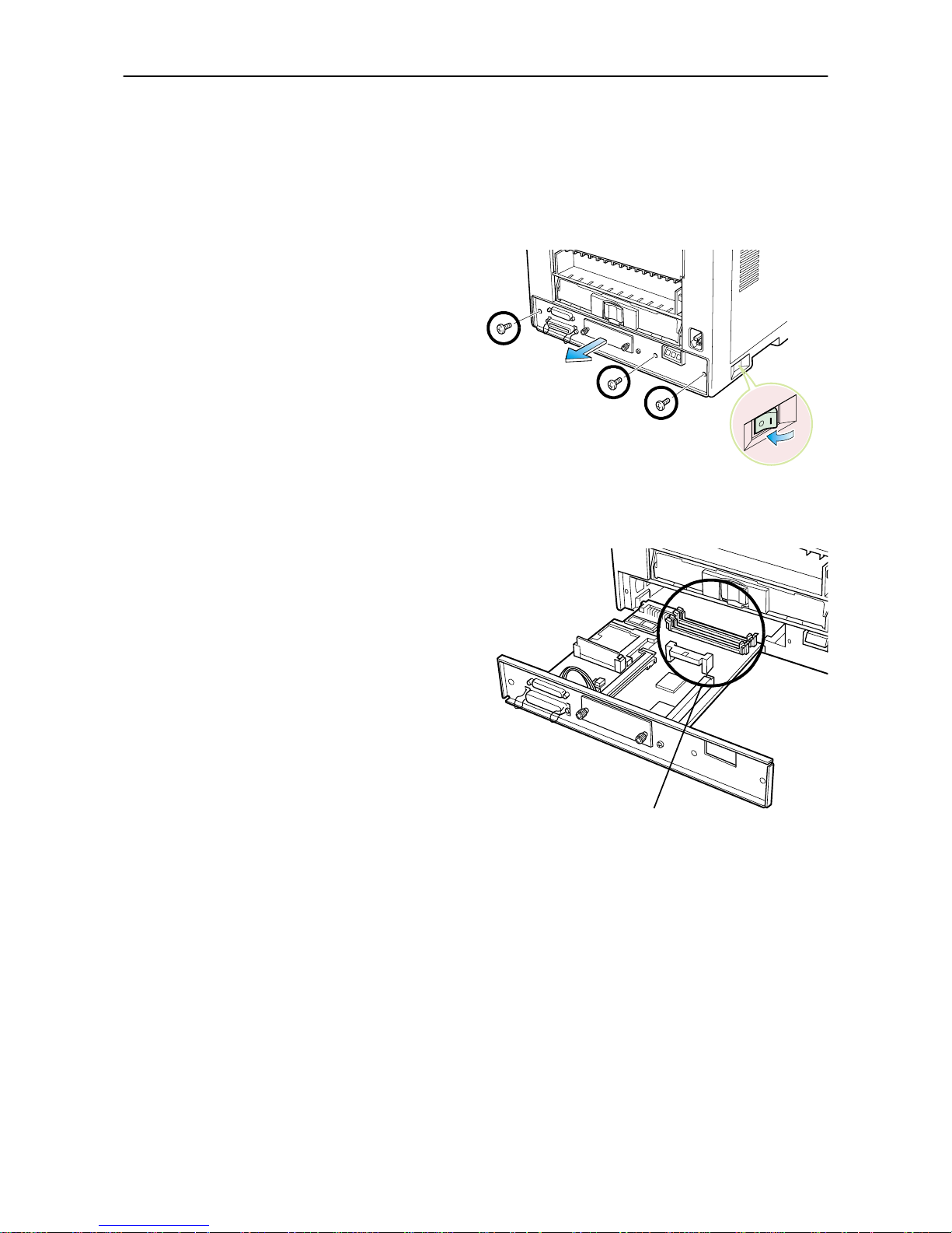
1.7. Memory Expansion Installation
1-24
Withdrawing the Main Circuit Board from the Printer
☛
Be sure to remove the memory card first if inserted in the printer's memory card slot.
Withdraw the main circuit board completely from the printer as follows:
1.
Turn the printer's power off. Unplug the printer's power cable and disconnect the printer from the host
computer.
2.
Remove the three screws from the printer's rear
cover.
3.
Pull the main circuit board all the way out of the
printer.
☛
Before pulling the main board out, clean an area
on the table, etc., at the back of the printer's rear
panel. Foreign objects, accidentally sticking to
the back of the main board, can cause serious
damage to the printer.
Install the SIMM as described on the next page.
Power OFF (O)
SIMM Sockets
Page 47
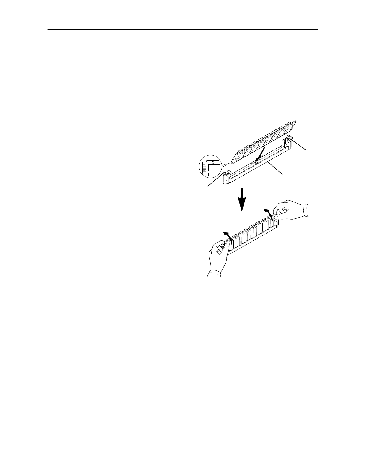
1.7. Memory Expansion Installation
1-25
SIMM to be used
See your dealer for purchasing information of the SIMMs that are best suited for use with this printer.
Eith er 4 MB, 8 M B, 16 MB o r 32 MB SIMMs can be used f or memory expans ion.
Installing and Removing SIMMs
Installing SIMMs
Insert the SIMM into the socket as shown right.
1.
Insert the connector end of the SIMM into the
socket.
2.
Carefully push the board up right until it snaps into
place. Make sure that the catches at the ends of the
socket fit into the holes at the ends of the SIMM
board.
SIMM
Catch
Socket
Catch
Page 48
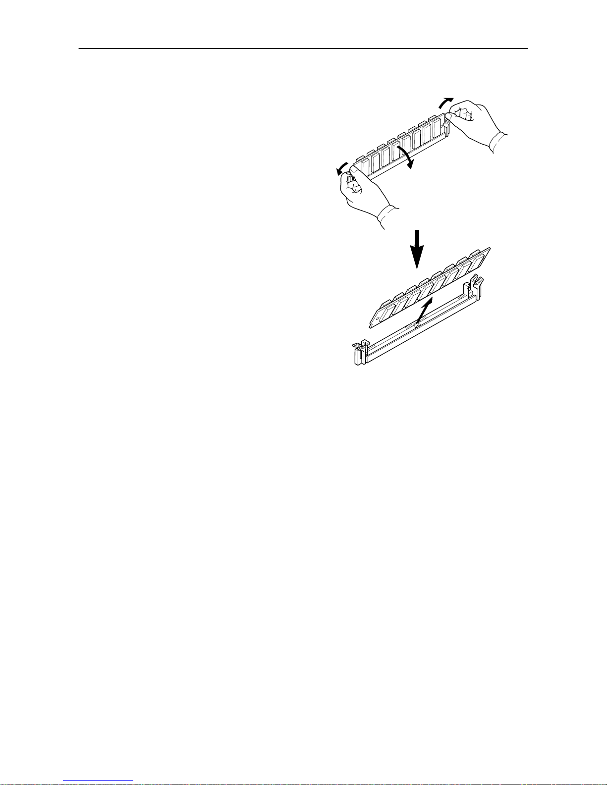
1.7. Memory Expansion Installation
1-26
Removing SIMMs
To remove a SIMM, carefully pull the end catches
slightly outwards and tilt the SIM M as shown, then pull
the SIMM out of the socket.
Reverse the procedure under Withdrawing the Main
Circuit Board from the Printer to put the main circuit
board back into the printer.
Testing the Expansion Memory
After you have finished installing SIMMs in the printer, test the printer to see if the installation has been
successful.
To test the expansion memory, proceed as follows:
1.
Make sure the power switch is off. Plug the power cord into the printer and turn power on.
2.
When the printer is on-line, press the STATUS key.
3.
If the installation has been successful, the amount of memory shown on the status page will correspond
with the amount of expanded memory. (The factory installed memory size is 8 MB for the DP-1400 and
16 MB for the DP-1800.)
Page 49
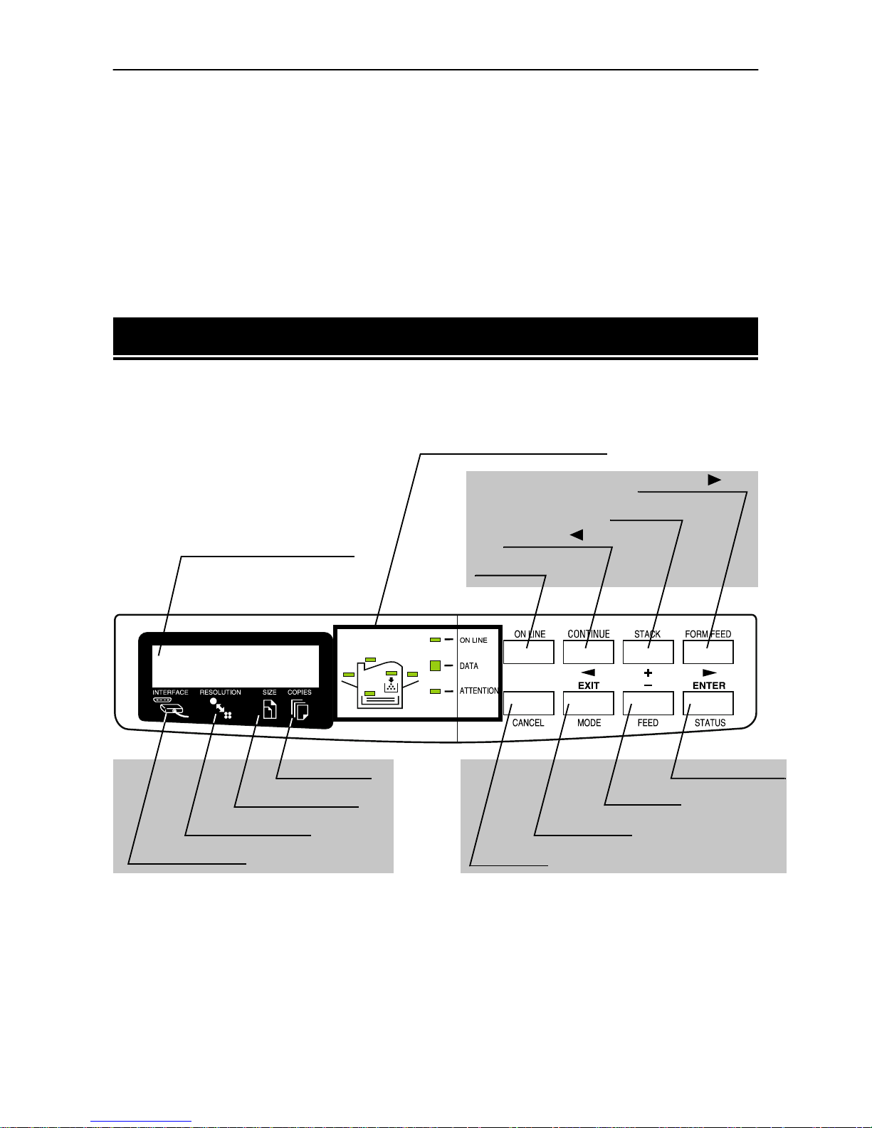
2.1. Control Panel
2-1
Chapter 2
Operating the Laser Printer
This chapter explains the printer's control panel and operating procedures. It covers
the fundamental information you will need to use the page printer.
2.1. Control Panel
The printer control panel comprises a message display, keys, and indicators, as shown below.
ENTER/STATUS key
(☛ Page 2-5)
Symbolic Indicators
(☛ Page 2-4)
FORM FEED/ Key
STACK/+ Key
CONTINUE/ Key
ON LINE Key
- /FEED Key
EXIT/MODE Key
CANCEL Key
Copy Indicator
Paper Size Indicator
Resolution Indicator
Interface Indicator
(☛ Page 2-5)
Message Display
(☛ Page 2-2)
(☛ Page 2-2, 3)
Page 50
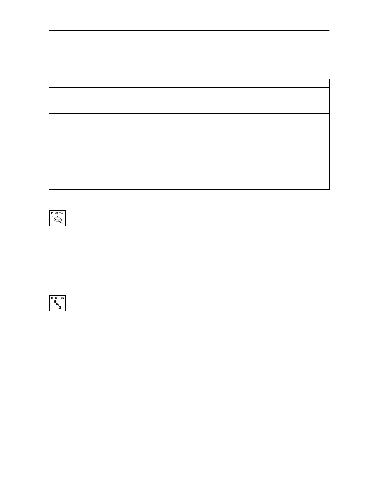
2.1. Control Panel
2-2
Message Display
The message display gives information in the form of short messages. The six messages listed below are displayed during normal warm-up and printing.
Other messages appear when the printer needs the operator's attention as explained in Chapter 5.
Interface Indicator
The interface indicator shows which of the printer's interfaces is currently active. It uses the following abbreviations:
PAR Standard bi-directional parallel interface
SER Serial interface (RS-232C/RS-422A)
OPT Optional interface
The PAR, SER, or OPT indicator flashes when the printer is receiving and has received all the data, and
then remains on.
Resolution Indicator
This shows the current printing resolution. The resolutions below can be switched on the control panel. The
default is 1200 dpi (Fast 1200 mode) in the PCL 6 and KPDL emulation mode and 300 dpi in other emulation
modes. The printer's resolution can be selected using the printer's control panel (See the last page in this
manual.). For 1200 dpi, there are two modes, Fast 1200 mode and Fine 1200 mode. See Mode Select Menu at
the end of this manual.
300 Print at 300 dpi.
600 Print at 600 dpi.
1200* Print at 1200 dpi (Fast 1200 mode) (Default).
1200 Print at 1200 dpi (Fine 1200 mode).
Message Meaning
Self test
The printer is self-testing after power-up.
Please wait
The printer is warming up and is not ready.
Ready
The printer is ready to print.
Processing
The printer is receiving data, generating graphics, reading an memory card, or printing.
Waiting
The printer is waiting for a command that says the job is over before printing the last
page. Pressing the
FORM FEED
key allows you to obtain the last page immediately.
Sleeping
The printer is in Sleep mode. The printer wakes from Sleep mode whenever a key on the
control panel is pressed, the cover is opened or closed, or data is received. The printer
then warms up and goes online. (The time that it takes the printer to enter Sleep mode
depends on the Sleep Timer setting.)
Cancelling data
Data inside the printer is being canceled.
FormFeed Time Out
The printer prints the last page after a waiting period.
Page 51
2.1. Control Panel
2-3
Paper Size Indicator
This is the paper SIZE indicator which indicates:
❒
the size of the current paper cassette (letter size for the U.S.A. and A4 for European countries).
The following abbreviations are used to indicate the paper sizes.
*
with only the MP tray feeding or optional envelope feeder (EF-100) installed.
**
with only the MP tray feeding.
☛
While the printer is
Processing
data to print, the SIZE indicator indicates the paper size selected
by the application software.
Copy Indicator
Indicates the number of copies set in the current interface (1- 999), and the number is reduced as printing
proceeds.
A4
ISO A4 (21 cm × 29.7 cm)
DL
ISO DL (11 × 22 cm)
*
A5
ISO A5 (14.8 cm × 21 cm)
C5
ISO C5 (16.2 × 22.9 cm)
*
A6
ISO A6 (10.5 cm × 14.8 cm)
**
b5
ISO B5 (17.6 × 25 cm)
**
B5
JIS B5 (18.2 cm × 25.6 cm)
EX
Executive (7-1/4 × 10-1/2 inches)
**
B6
JIS B6 (12.8 cm × 18.2 cm)
**
#6
Commercial 6-3/4 (3-5/8 × 6-1/2 inches)
*
LT
Letter (8-1/2 × 11 inches)
#9
Commercial 9 (3-7/8 × 8-7/8 inches)
*
LG
Legal (8-1/2 × 14 inches)
HA
Japanese Postcard (10 × 14.8 cm)
*
MO
Monarch (3-7/8 × 7-1/2 inches)
*
OH
Return Postcard (20 × 14.8 cm)
*
BU
Business (4-1/8 inches)
*
CU
Custom Size (14.8 × 21 cm to 21.6 × 35.6 cm)
Page 52
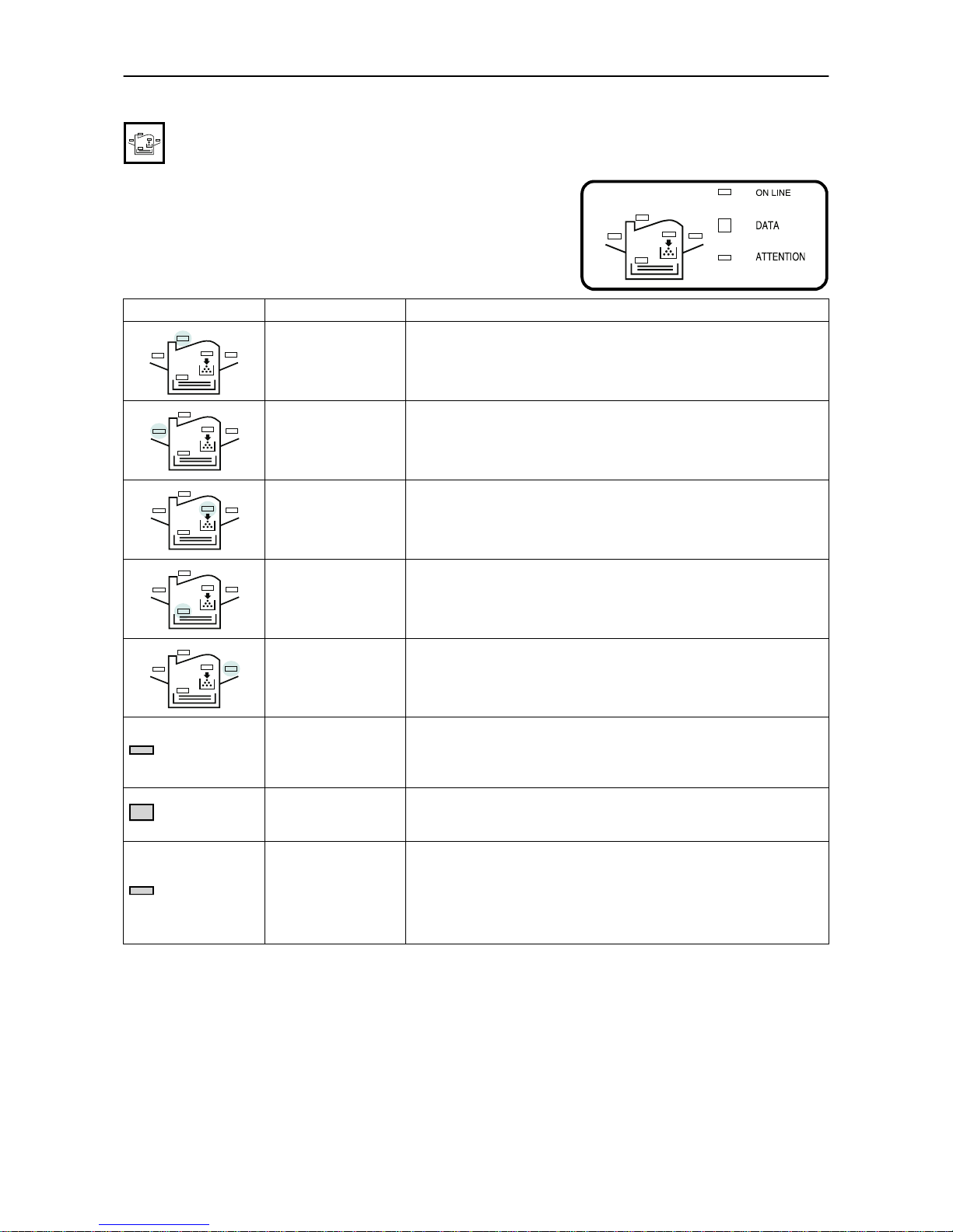
2.1. Control Panel
2-4
Symbolic Indicators
The symbolic indicators light during normal operation and when the
printer needs attention.
Indicator Name Description
Face -down
stack indicator
Flashing:
Indicates the possibility that paper may be jammed at this
point, open and remove any jammed paper. See Section 5.6.
Lit:
Indicates when printed pages are delivered to the face-down out-
put tray.
Face -up
stack indicator
Flashing:
Indicates the possibility that paper may be jammed at this
point, open and remove any jammed paper. See Section 5.6.
Lit:
Indicates when printed pages are delivered to the face-up output
tray, or to the option stacker if installed.
Toner indicator
Flashing:
Indicates there is insufficient toner.
Lit:
Indicates that the printer is out of toner. Replace with a new toner
container.
See Section 4.1.
Cassette feed
indicator
Flashing:
Indicates the possibility that paper may be jammed at this
point, open and remove any jammed paper. See Section 5.6.
Lit:
Indicates when paper is fed from the paper feed cassette.
MP tray indicator
Flashing:
Indicates the possibility that paper may be jammed at this
point, open and remove any jammed paper. See Section 5.6.
Lit:
Indicates when paper is fed from the MP tray, or the option envelope feeder if installed.
ON LINE
On-line indicator
Flashes when a memory error has occurred. (See Table 5.3.) Lights
when the printer is on-line. The printer prints received data. Goes off
when the printer is off-line. The printer stores but does not print
received data.
DATA
Data indicator
Flashing:
Indicates data transfer is taking place.
Lit:
Indicates either that data is being processed, or that data is being
written to the memory card.
ATTENTION
Attention
indicator
Flashing:
Indicates when the printer needs maintenance attention
or the printe r is warming up (
Please wait
). Read the m essage on
the message display and consult Chapter 5.
Lit:
Indicates when a problem or an error occurs which may be cleared
by the user. (For example, the paper feed cassette is empty.) Read the
message in the message display and consult Chapter 5.
Page 53
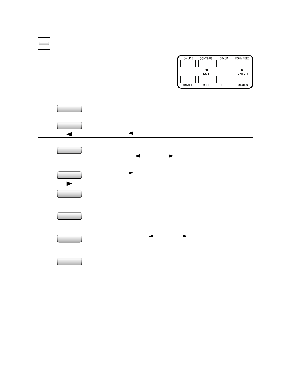
2.1. Control Panel
2-5
Control Keys
The control panel keys are used to configure the printer.
☛
Settings made with these keys effect only the interface currently in use.
☛
Most of the panel functions can also be controlled by PRESCRIBE 2e commands or commands generated by application software. The printer obeys the most recently received printer settings sent
from the application software, or from the printer driver, which take priority over control panel settings.
Key Function
ON LINE
Switches the printer on-line and off-line.
CONTINUE
1.Depending on the message being indicated, there are cases where operation will
continue after pressing the
CONTINUE
key. If such a messag e is disp lay ed, o per a-
tion will be resumed after pressing this key. (See Ta ble 5.3)
2.Used as the key in the mode selection function.
STACK
+
1.Selects whether printed pages are delivered to the face-down, face-up tray, or
optional sorter/stacker (if installed).
2.Lets you access the desired item or enter numeric values. In some of the control
procedures, the (
CONTINUE
) and (
FORM FEED
) keys are used to enter or exit
the sub items.
FORM FEED
1.Prints and feeds out one page.
2.Used as the key in the mode selection function.
CANCEL
Abandons a printing job, resets numeric values, or cancels a setting procedure.
EXIT
MODE
1.When pressed during mode selection, terminates the setting and returns to the
Ready
condition.
2.Used to select the emulation, font, character code set; to read an memory card
and others (See Section 2.3 and the last page in this manual.).
–
FEED
1.Enables access to the desired item or entering of numeric values. In some of the
control procedures, the (
CONTINUE
) and (
FORM FEED
) keys are used to enter
or exit the sub items.
2.Selects the cassette feed or MP tray feed.
ENTER
STATUS
1.Finalizes numeric values and other selections.
2.Prints a page of status information on all interfaces together (The printer must
be on-line.).
Page 54
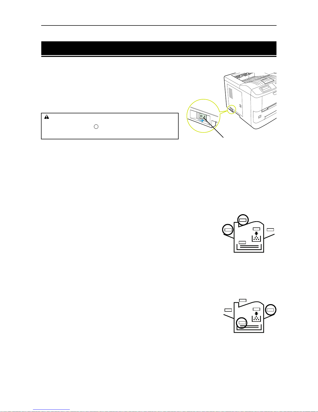
2.2. Operating Procedures
2-6
2.2. Operating Procedures
Switching Power On
Check that the power cord is securely plugged in at both ends.
Check that the printer is connected to the computer. In switching
power on, the general rule is to switch on printer power first, computer power second.
1.
Push the power switch to the ON ( | ) position.
2.
Wait for the printer to warm up. During warm-up the message display indicates Self test.
At the end of the warm-up period, the ON LINE indicator lights, and the message display indicates Ready.
The printer is now ready to print.
Stack Selection
The
STACK
key selects the tray to which the printed pages are delivered. The
STACK
key can be used whenever
the message display indicates Ready.
Press the
STACK
key. The selection toggles and is momentarily displayed in the message display as:
Face-up tray
Face-down tray
If you have installed the optional sorter or stacker, Sorter or Bulk
stacker will also be displayed.
The current selection is indicated by a green light on the printer symbol above the
key.
Also, if the printer is being used with the optional sorter or stacker, the destination of the paper from each
can be selected.
Feed Selection
The
FEED
key selects the paper feed cassette [Cassette] or MP tray
[MP tray] (or the option paper feeder[s], if installed) as the paper source. The
FEED
key can be used whenever the message display indicates Ready or Add
paper.
Press the
FEED
key. The selection cycles and is momentarily displayed in the mes-
sage display as:
Cassette
(paper size)(paper type)
MP tray[MP tray mode]
(paper size)(paper type)
CAUTION
If the printer will not be used for a short period o f time (overnig ht, etc),
turn the main switc h OFF ( ). If it will not be us ed for an exten ded
period of time (vacations, etc) , remove the power plug from the outlet
for safety purposes d uring the time the printer is not in use.
Power Switch
Page 55

2.2. Operating Procedures
2-7
If you have installed the optional paper feeder, the cassette in the printer appears on the display as
Cassette 1, and the cassettes in the paper feeder appear as Cassette 2 and Cassette 3.
Also, if the Envelop Feeder or Bulk Feeder is installed then MP tray is not displayed and EF or Bulk
feeder is displayed instead.
The current selection is indicated by a green light on the printer symbol above the key.
On-line/Off-line Setting
By pressing the
ON LINE
key you can change the printer between the on-line state, in which it prints the data
it receives from the computer, and the off-line state, in which it stores the data for printing later.
1.
Make sure that the message display indicates Ready.
2.
Press the
ON LINE
key.
If the printer is on-line, it changes to off-line. If the printer is off-line, it changes back to on-line.
The ON LINE indicator lights when the printer is on-line.
Going off-line may or may not halt communication between the printer and computer, depending on details
of the current interface. While off-line, the printer continues to accept any data that arrives until the current
interface buffer is full, at which point it instructs the computer to stop sending data. Data stored while offline are printed when the printer is returned to the on-line state.
Canceling Printing
Perform the following procedure when you wish to cancel printing after it has begun.
1.
Check if the message Processing is displayed in the message display.
2.
Press the
ON LINE
key to take the printer offline.
3.
Perform the necessary procedure on the computer to halt printing.
4.
Press the
CANCEL
key.
5.
The message Print Cancel? will appear in the message display and the interface to be canceled
will be displayed.
Parallel
Serial
Option (appears only when an optional interface is installed)
6.
Selecting the interface to cancel using the + or – key and then press the
ENTER
key. Printing from the
interface selected will be stopped.
A few pages may be printed even after the
CANCEL
key is pressed as remaining data received before the
CANCEL
key was pressed is printed.
The message Print Cancel? Current job will also be displayed when the
CANCEL
key is
pressed for the purpose of stopping the printing of status pages or font lists from the control panel. When
the
ENTER
key is pressed, the message Cancelling data appears in the message display and
printing stops after the printer finishes printing the current page.
Press the
CANCEL
key again if you wish to stop the cancellation of printing.
Press the
ON LINE
key to put the printer back online to continue with other print jobs.
☛
Canceling data from the computer using the
CANCEL
key will restore temporary settings to their
default values. (The same status resulting from executing the PRESCRIBE 2e RES command.)
☛
It is impossible to cancel printing of just one side when printing in duplex mode using an optional
duplexer (AD-34).
Page 56

2.2. Operating Procedures
2-8
Status Printout
If you want to check the printer's current status, including memory available, and option settings, you can
find the information you need on the status page. To print out a status page, the printer must be on-line.
Proceed as follows:
1.
Make sure the message display indicates Ready.
2.
Press the
STATUS
key. The printer prints a page of status information.
The message display indicates Processing during printing of the status page, then returns to Ready.
For a full description of the status page, see next page.
☛
Items and values on the status page may vary depending on the printer model and printer's firmware version.
Page 57
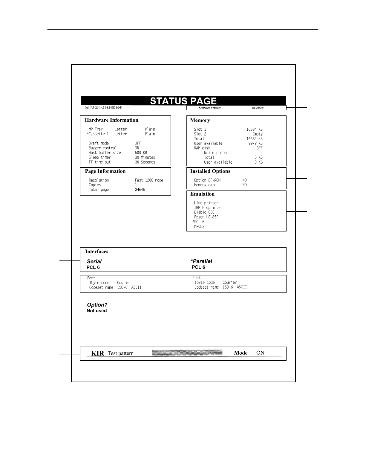
2.2. Operating Procedures
2-9
Sample Status Page
2
3
7
8
9
1
4
5
6
Page 58

2.2. Operating Procedures
2-10
1 — Software version
This information shows the software version and date of issue of the printer.
2 — Hardware information
This information shows the currently selected paper feed source (indicated by an asterisk), paper size, and
main settings of the printer.
3 — Page information
This information shows the currently selected resolution and number of copies.
4 — Memory usage
This information shows the amount of total memory installed in the printer and the amount of currently
available memory.
5 — Installation Options
This shows the options currently installed in the printer.
6 — Emulation
This shows all available emulations and the currently selected emulation (marked with an asterisk). The
printer is shipped from the factory set to PCL 6 emulation.
7 — Interface information
This information shows all interfaces installed in the printer and the currently selected interface.
8 — Fonts at startup (for each interface)
This shows the font automatically selected when the printer starts up (default font). It is possible to set different fonts for the parallel interface and the serial interface. The figure on page 2-9 shows default settings.
The font is set to Courier font (font number: I000).
This also shows font information similar to the column below if an optional interface is installed.
9 — KIR test pattern
This is used when setting the printer's KIR mode. For details, see page 2-24.
Form Feed
Depending on the software, the message Waiting may be displayed in the message display when you get
to the end of a print job. This occurs when the software does not issue a final form feed to the printer indicating the end of the print data. If you wait awhile, FormFeed TimeOut will be displayed and the last
page will be printed automatically. Pressing the
FORM FEED
key allows you to finish printing immediately.
1.
Check if the message display reads Waiting.
2.
Press the
FORM FEED
key. The message display will now read Processing and the last page will
print.
☛
The
Waiting
display may also appear due to interruptions in printed data while the computer is
processing data. Pressing the
FORM FEED
key unnecessarily when the message display reads
Waiting
will result in a form feed.
Page 59
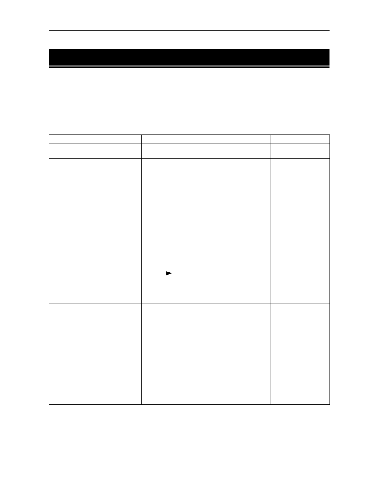
2.3. Using the Mode Select Menu
2-11
2.3. Using the Mode Select Menu
This section explains how to use the
MODE
key on the control panel. The
MODE
key allows you to set or change
the printer environment such as the number of copies to make, emulation, page orientation, code set, etc. to
your specific needs.
The following items can be selected by using the
MODE, +
and –, and
ENTER
keys. Also, the diagram on the last
page in this manual gives a quick reference to the full options and the sequence of selection.
Mode Select Menu
Item Function Default Setting
Print
Menu Map
Prints a menu map with the current settings on it. —
Interface >
Selects the interface on which the control panel settings are effective. This setting affects only the currently active interface.
Parallel setting has a sub item in which one of four
data transmission modes can be selected —
Nibble (high), Auto, Normal
, or
High speed
Serial setting has five sub items, and sets the following RS-232C/RS-422A parameters:
Baud rate
Data bits
Stop bits
Parity
Protocol
If an optional network board is installed, also makes
the network settings.
Parallel
Auto
9600
8
1
None
DTR(pos.)&XON
Emulation >
Changes the emulation mode on the current interface. The key allows access to sub item
>Code set
.
Also with KPDL emulation, print settings can be
made when there is an error or alternative emulation.
PCL 6
Font >
Select the current interfa ce font. The default number
for selecting an internal font is I000 (this is the number for Courier). If there are optional fonts in the
printer other than the internal ones, you can specify
them by switching to the
Option
display.
Depending on the type of optional font, the symbols
used at the start of the font number change as follows:
Soft font (Download): S
Fonts resident in a Memory Card: M
Fonts resident in a RAM disk: H
Fonts resident in an optional ROM: O
This menu also allows printing the font lists, selecting Courier, Letter Gothic, and selecting the size and
pitch of the font.
Internal
I000 (Courier)
Page 60
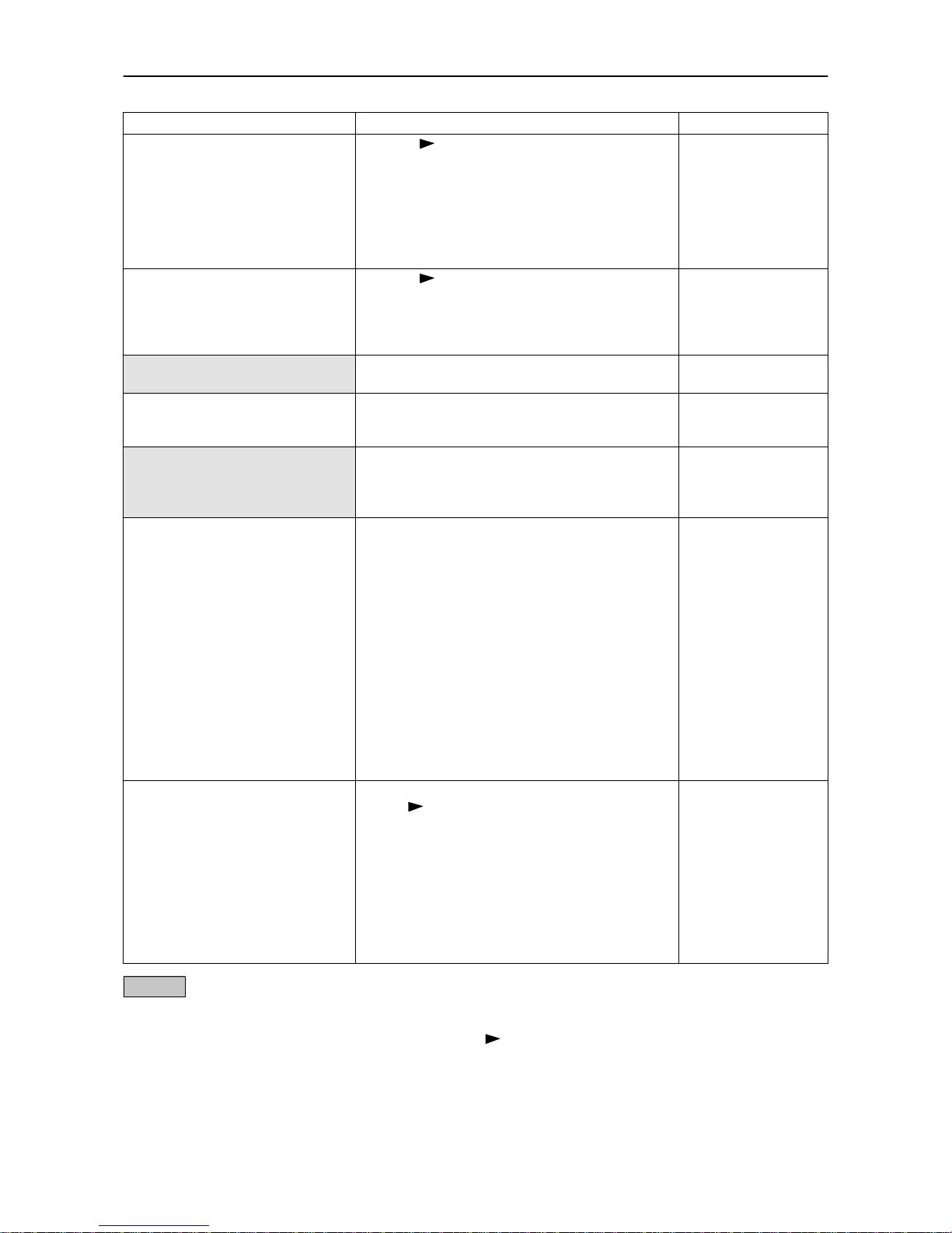
2.3. Using the Mode Select Menu
2-12
/ *: These items are available only when the printer is installed with the applicable option unit/kit.
For ite ms wi th th e > mark on the message display, the (
FORM FEED
) key lets you go down to the sub items
which give access to more items to change the relevant settings.
Page set >
Press the key to set the following page printing
method.
Number of copies
Page orientation
Page protect
LF action
CR action
Wide A4
001
Portrait
Auto
LF only
CR only
Off
Print quality >
Press the key to set the following print quality.
KIR mode
Draft mode
Resolution
Print density
On
Off
Fast 1200 mode
03
Opt. ROM >
Reads information from the option ROM installed in
the printer's main board.
—
RAM DISK mode >
The following settings can be made from sub-menus
when the total printer memory is 12 MB or more and
this mode is set to On.
Off
MEMORY CARD >
R e a d s o r w r i t e s d a t a f r o m o r t o a n m e m o r y c a r d i n t h e
printer's memory card slot. Also, this menu allows
deletion of data from an memory card; and formatting the memory card.
—
Paper handling >
The following operations can be performed from submenus on paper type.
MP tray mode
Paper size for MP tray
Paper type for MP tray
Paper size for optional envelope feeder
Paper type for optional envelope feeder
Paper size for optional bulk feeder*
Paper type for optional bulk feeder*
Cassette size for custom sizes
Paper type for Cassette 1-3
Duplex printing mode*
Optional sorter mode*
Override A4/Letter
Set up the custom paper type
Reset the custom paper type
First
A4 or Letter
Plain
DL or Business
Envelope
A4
Plain
216 mm × 356 mm
Plain
None
Stacker
Off
—
—
Others >
The following sub-menus can be displayed by pressing the key and then the + and – key
Message language setting
Automatic form feed timeout setting
Sleep timer setting [See page 2-22.]
Receive data damping [See page 2-23.]
Printer reset
Display total number of printed pages
Resource setting
Alarm (buzzer) setting
Service (for service personnel)
English
30 sec.
30 min.
—
—
—
Off
On
—
Item Function Default Setting
Page 61

2.4. Configuring Interfaces
2-13
2.4. Configuring Interfaces
The printer is equipped with both a parallel and serial interface. Independent settings can be made for each
interface. Optional interface can also be installed.
To configure each interface, press the
MODE
key and use the + or – k e y t o s e le c t t h e i n t e r f a c e y o u w i s h t o m a k e
settings for.
☛
This interface selection does not select which interface data will be received from. The printer automatically selects that interface.
Parallel Interface
The parallel interface mode of this printer supports a bi-directional/high-speed mode. Normally, this interface is used under the default setting Auto, see Appendix C. After setting the interface, be sure to reset the
printer or turn the power off at least once. The new setting will be enabled thereafter.
Page 62

2.5. RAM DISK
2-14
2.5. RAM DISK
A RAM DISK can be set up as a virtual media device by setting a given amount of the total printer memory
as the RAM DISK. (This is only available for the DP-1400 when the printer's memory has been expanded to
12 MB or mor e.) By se ttin g up a R AM D ISK e lect r oni c sort i ng c a n be d one. (T his c uts do wn th e tot al ti m e of
printing.) Note however that data written to the RAM DISK is lost if the power to the printer is turned off
or the printer is reset. RAM DISK settings can be made from the printer's control panel.
☛
The RAM DISK is set from the printer's user memory. The printer's printing speed may therefore drop
or insufficient memory errors result depending on the value of the RAM DISK setting.
Setting the RAM DISK Size
1.
Press the
MODE
key.
2.
Press the + or – key and select RAM DISK mode >.
3.
The default setting is Off. Pressing the
ENTER
key will cause a ? to flash. Press the + or – keys to dis-
play On and then press the
ENTER
key.
4.
Press the key to display >RAM DISK size.
5.
Press the
ENTER
key again, and change the RAM DISK size using the + or –key. It is not possible to make
a setting that exceeds total printer memory. The default value for the RAM DISK is the total printer
memory minus 9 MB. This parameter may be set anywhere from 01 to 63 depending on the available
printer memory. Press the
EXIT
key if you want to cancel the setting.
6.
Once the desired RAM DISK size is displayed, press the
ENTER
key.
7.
Press the
EXIT
key. Then turn the printer's power off and on again. The setting will be activated after
restart.
RAM DISK Operations
The following operations are available with the RAM DISK.
❒
Read Data
❒
Write Data
❒
Delete Data
❒
Print a List of Data Names
Procedures for all operations are the same as for a memory card. Please see the memory card item for the
given procedure.
Page 63

2.6. Operating a Memory Card
2-15
2.6. Operating a Memory Card
Hints on Writing Fonts to the Memory Card
Some memory card writer utility programs are available for writing data to the memory card. If you write
fonts into a memory card, we recommend you write them as font data and not as host data. Fonts written in
a memory card as font data are automatically loaded in the printer when it is switched on and are usable on
all the printer interfaces simultaneously. The printer reads only the header part of these fonts into its memory and therefore these fonts do not occupy a large area in the printer's memory.
If you write the fonts in the memory card as host data, the fonts are transferred directly from the memory
card into the printer's memory when the card is read. This may require extra memory to be installed in the
printer as they usually occupy a great amount of the printer's memory. Moreover, use of the fonts is restricted
on only the interface that was active during the fonts were read from the memory card.
To properly write font data into the memory card, refer to the memory card writer manufacture's instructions.
Reading Fonts/Data from a Memory Card
If the memory card is already inserted in the slot when the printer is powered on, the fonts are automatically
read into the printer. To reread the fonts from a memory card, use the >Read fonts function.
☛
The PRESCRIBE 2e FRPO I0 command specifies the name of the partition in the memory card to be
read automatically at power up. See
PRESCRIBE 2e Programming Manual, Chapter 5
.
Writing Data to a Memory Card
A memory card can hold up to 127 data partition names, depending on its capacity. When writing to the card,
a name is assigned automatically. You can use the procedure later in this section to print a list of data names
for confirmation.
☛
You cannot write font data to a memory card with the printer.
To write data to a memory card, proceed as follows.
First check that the memory card can be writable (that the memory card is properly formatted, not writeprotected, and its internal battery is not exhausted, for example). Otherwise, the >Write data message to be explained below will not be shown on the message display.
☛
If the card inserted in the memory card slot is not formatted, the
>Format
option will automati-
cally appear on the display. Refer to
Formatting a Memory Card
which follows this section and for-
mat the memory card.
1.
With the message display showing >Write data, press the
ENTER
key. A blinking question mark
will appear as follows:
>Write data ?
2.
Press the
ENTER
key. The message display changes to show Processing, then to Waiting.If you
want to abandon writing, press the
CANCEL
key.
3.
In this state, send the file from the computer to the printer as in the example below.
Example:
To send the file (data) TEST.TXT on drive C, enter the following at the DOS prompt (C:\):
COPY TEST.TXT PRN
The file is written onto the memory card given a destination name (also referred to as a partition name)
which the printer automatically assigns one after another as follows:
Page 64
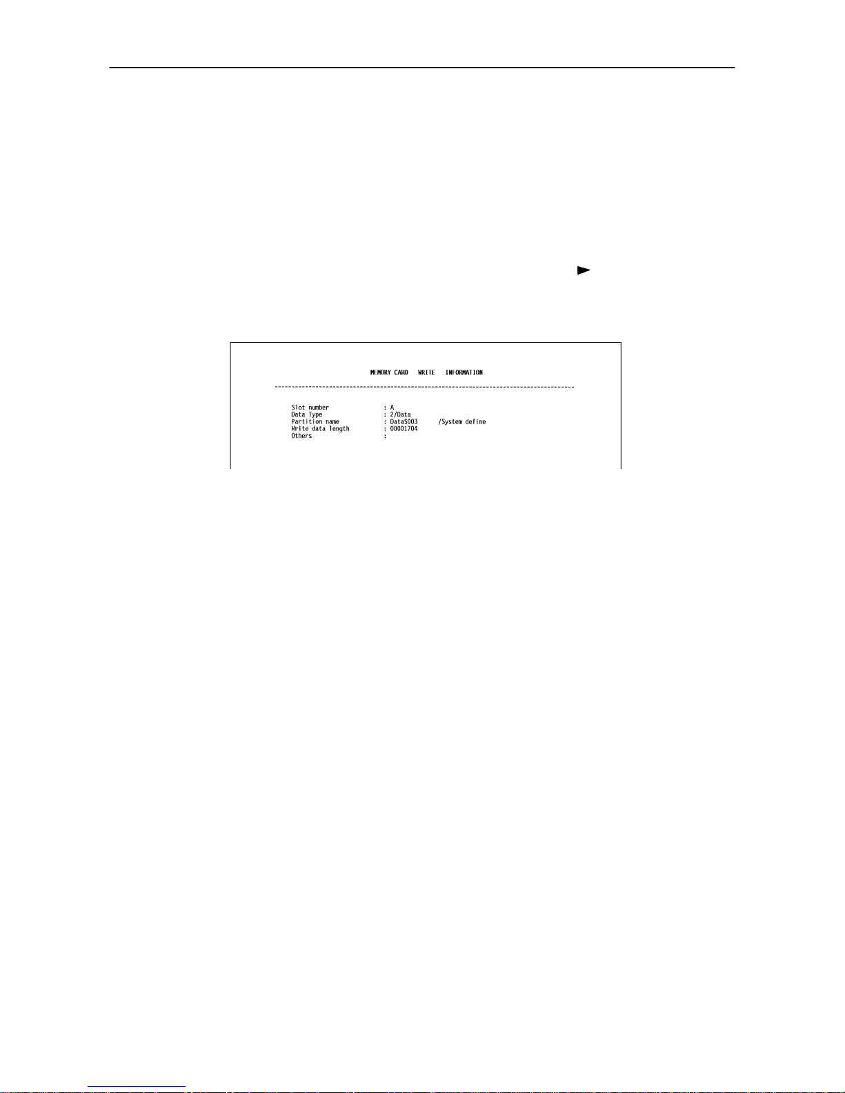
2.6. Operating a Memory Card
2-16
DataS001 (first data), DataS002 (second data), DataS003 (third data),
... DataS127 (last data)
In the example above, if the file TEST.TXT is the first data to be written onto the memory card, the des-
tination name will be DataS001.
By using the PRESCRIBE 2e RWER W (write memory card) command to write data to a memory card,
you can change the destination name to be the same as the original name or any other name you desire.
As the printer receives data, the message display changes to Processing, then when the end of the
data is received, the message display changes to Waiting.
4.
Check that the message display has changed to Waiting, then press the (
FORM FEED
) key. This
writes the file to the memory card and instructs the printer to automatically print out a memory card
write information page as shown below.
Data type. Type of data written (currently only type 2 is supported).
Partition (data) name. The destination name of data written to the card.
Write data length. The size of the written data on the memory card in bytes.
Others. Error information.
When the memory card write information page is printed, the message display returns to Ready.
If the writing was not completed successfully, an error code appears on the message display. For details,
see Section 5.5 Indicators and Messages. If this happens, press the
CONTINUE
key. The message display
returns to Ready.
5.
Repeat above steps until you have transferred all data (files) that you want to write to the memory card.
Each time you finish writing data, a memory card write information page is printed from the printer
showing the information explained in step 4 above, but pertaining only to the data just written. To see
all data contained in the memory card at once, print a list of data names as explained on the last page of
this manual.
Del eting Data from a Mem ory Ca rd
It is possible to use the printer to delete data from a memory card one by one.
First check that the memory card is writable (for example that the memory card is not write-protected, data
exists on the card, and its internal battery is not exhausted). Otherwise, the >Delete data menu will
not be shown on the message display.
Page 65
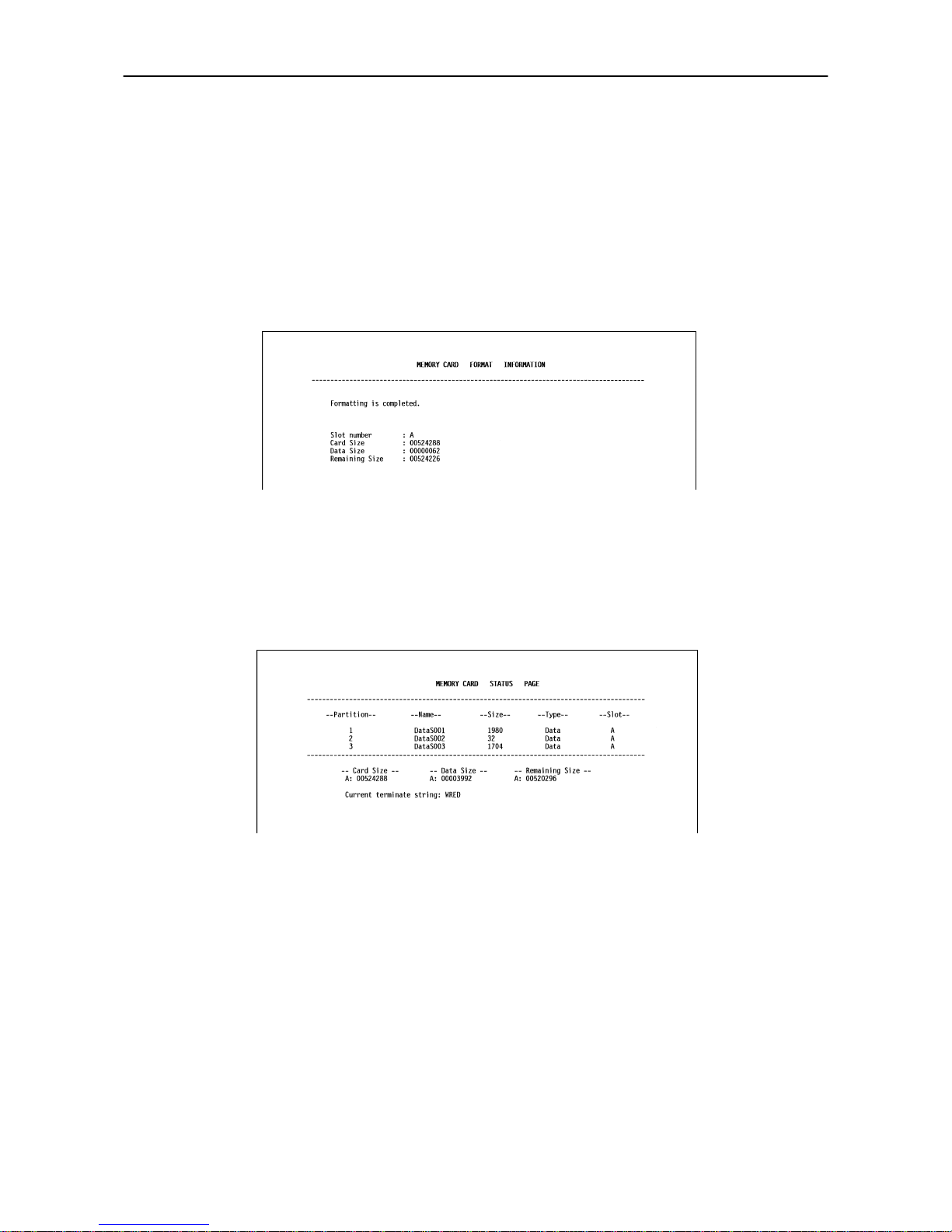
2.6. Operating a Memory Card
2-17
Formatting a Memory Card
Formatting allows data to be written to the card. A new memory card must be formatted before it can be used
in the printer.
☛
Formatting destroys any existing data on the memory card.
First che ck th a t th e m emo ry car d is w rita ble ( for e xampl e th a t the m emo ry ca rd is n ot wr ite- prot ected , and
its internal battery is not exhausted).
When the formatting operation is successfully completed, the printer automatically prints out a formatting
information page as shown below.
Card size. The total size of the memory card memory in bytes.
Data size. The size the printer uses for its system in bytes.
Remaining size. The size remaining in the memory card for storing data in bytes.
Printing a list of data names
The printer prints a list of all data names (referred to as partitions) stored in a memory card for reference.
(Printing a list is also available for a font card.)
The printout (example above) includes the following information.
Partition (data) number. Reference number for each written data.
Name. The destination name of the written data as assigned automatically by the printer.
Size. The size of the written data in bytes.
Type . The type of the written data i.e., whether it is host data (Data) or font data (Font).
Card size. The total capacity of the memory card in bytes.
Data size. The total size of the data stored in the memory card in bytes.
Remaining size. The size of the capacity remaining in the memory card for storing further data, including the amount of memory
that the printer uses for its system (approximately 70 bytes).
Current terminating string. The PRESCRIBE 2e command that terminates a writing operation when writing to memory card
using the PRESCRIBE 2e RWER W command; usually WRED.
Page 66
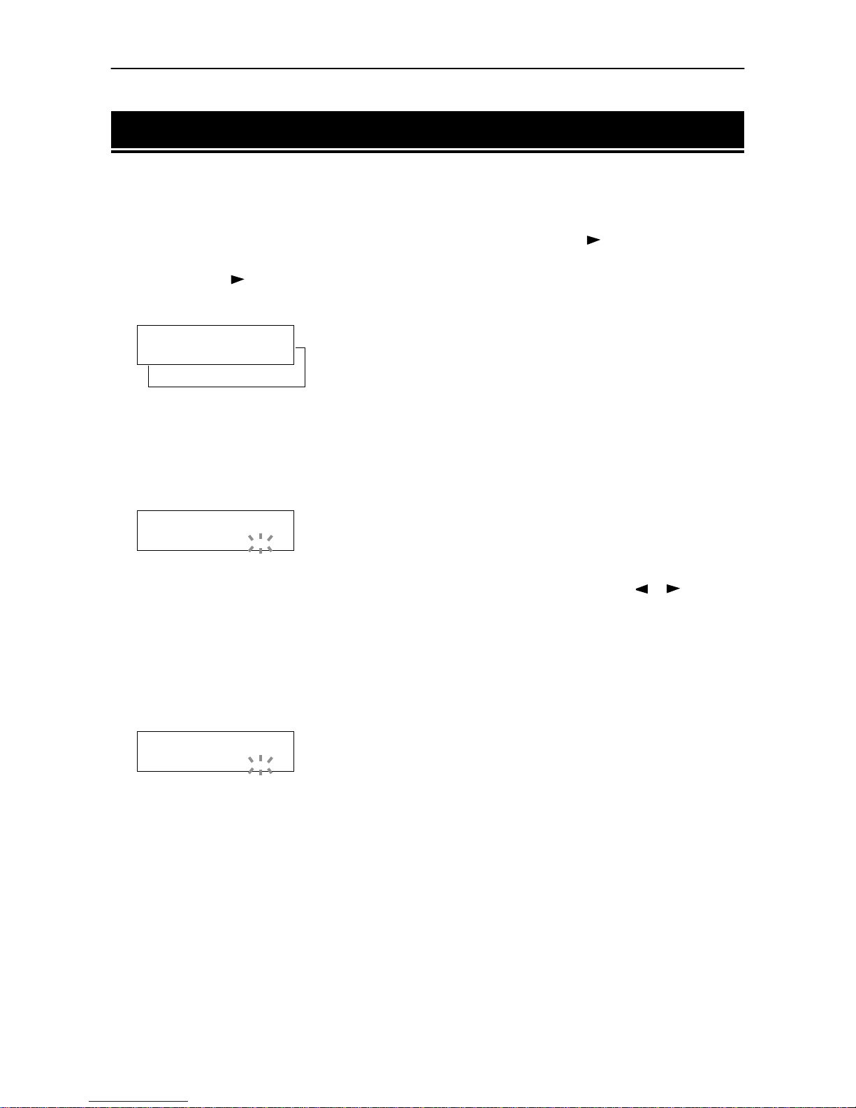
2.7. Setting Custom Sizes
2-18
2.7. Setting Custom Sizes
When setting sizes other than A5, A4, B5, Letter or Legal into the paper cassette, set the size of the paper to
be used into the printer by the following procedure.
1.
Display Paper handling> on the printer's display panel and press the key. Then use the + and
–
keys to display >Cassette size >.
2.
By pressing the key >>Unit appears as shown in the diagram below (The unit of the paper length).
You can select mm or inch by using the + and – keys.
3.
With the unit settings completed, >>X dimension appears as shown in the diagram below (the
paper width setting). Press the
ENTER
key whi le in this sta te and the curso r begins to fla sh.
☛
The width that can be set must be in the range of 148-216mm (5.83-8.5 inches).
4.
By pressing the + and – keys the numbers above the cursor change. By pressing the or keys the
position of the cursor moves.
5.
When you have input the desired custom size, press the
ENTER
key to complete the width setting.
6.
With the width settings completed, press the + and – keys and >>Y dimension appears as shown
below (the paper length setting). Set this in the same way as the width setting.
☛
The length that can be set must be in the range of 210-356mm (8.27-14.02 inches).
>>X dimension
216 mm
>>Y dimension
356 mm
>>Unit
inch
>>Unit
mm
_
_
Page 67
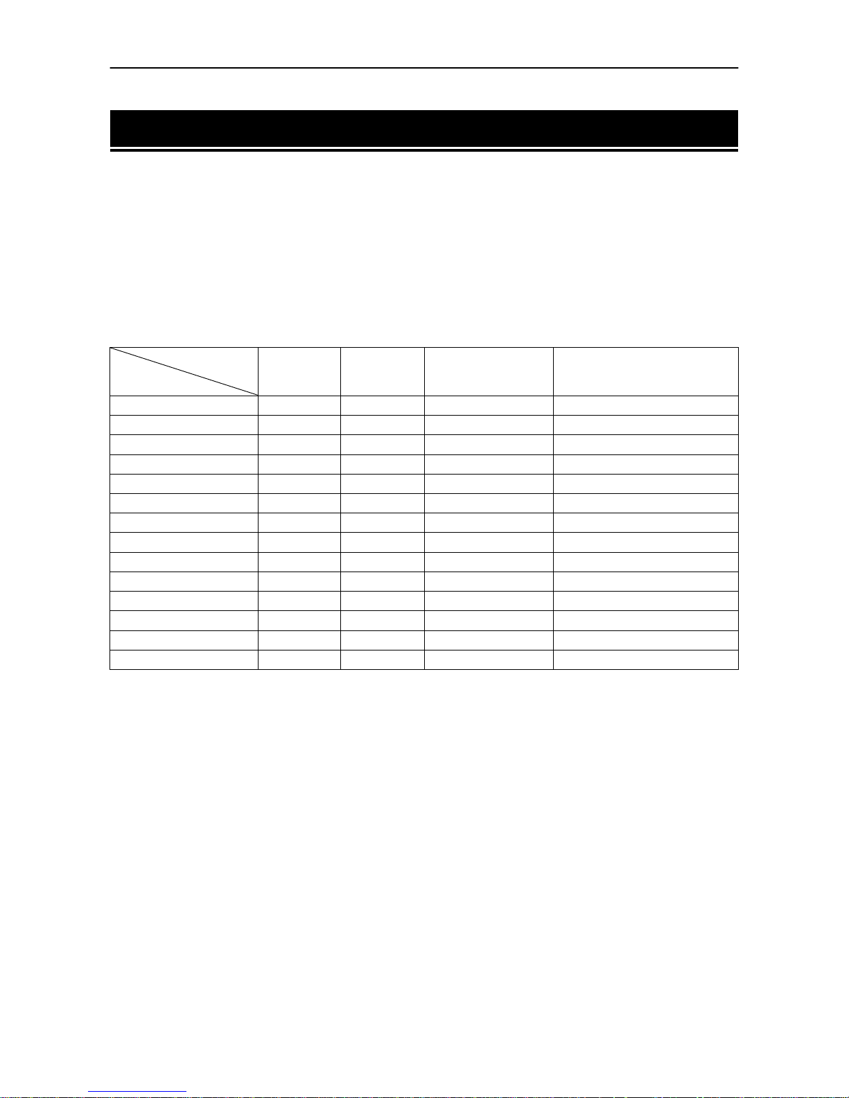
2.8. Setting the Paper Type
2-19
2.8. Setting the Paper Type
This printer is capable of printing under the optimum setting for the type of paper being used.
Setting the paper type for the paper source from the printer's control panel will cause the printer to automatically print in the mode best suited to that type of paper. This allows you to easily achieve high-quality
printing results. A different paper type setting can be made for each paper source including the multipurpose
tray. Not only can preset paper types be selected, but it is also possible for the user to define and select customized paper types.
The following types of paper can be set. For details on paper, please see Appendix B.
Cassette, Media Type and Custom Settings
O
: Can be stored×: Cannot be stored
*: This is a paper type defined and registered by the user. Up to eight types of user settings may be defined. A number
from 1 to 8 is used in place of the #. For details on setting user types, please see page 2-20.
Pap er f eed sou rce
Paper Type
MP tray
Bulk feeder
Cassette
EF
(Envelope feeder)
Duplex path
(MP tray available only
in Cassette mode)
Plain
OO O O
Transparency
O ×× ×
Preprinted
OO O O
Labels
O × O ×
Bond
OO O O
Recycled
OO O O
Vellum
O ×× ×
Rough
OO O O
Letterhead
OO O O
Color
OO O O
Prepunched
OO O O
Envelope
O × O ×
Cardstock
O × O ×
Custom #
*
OO O O
Page 68
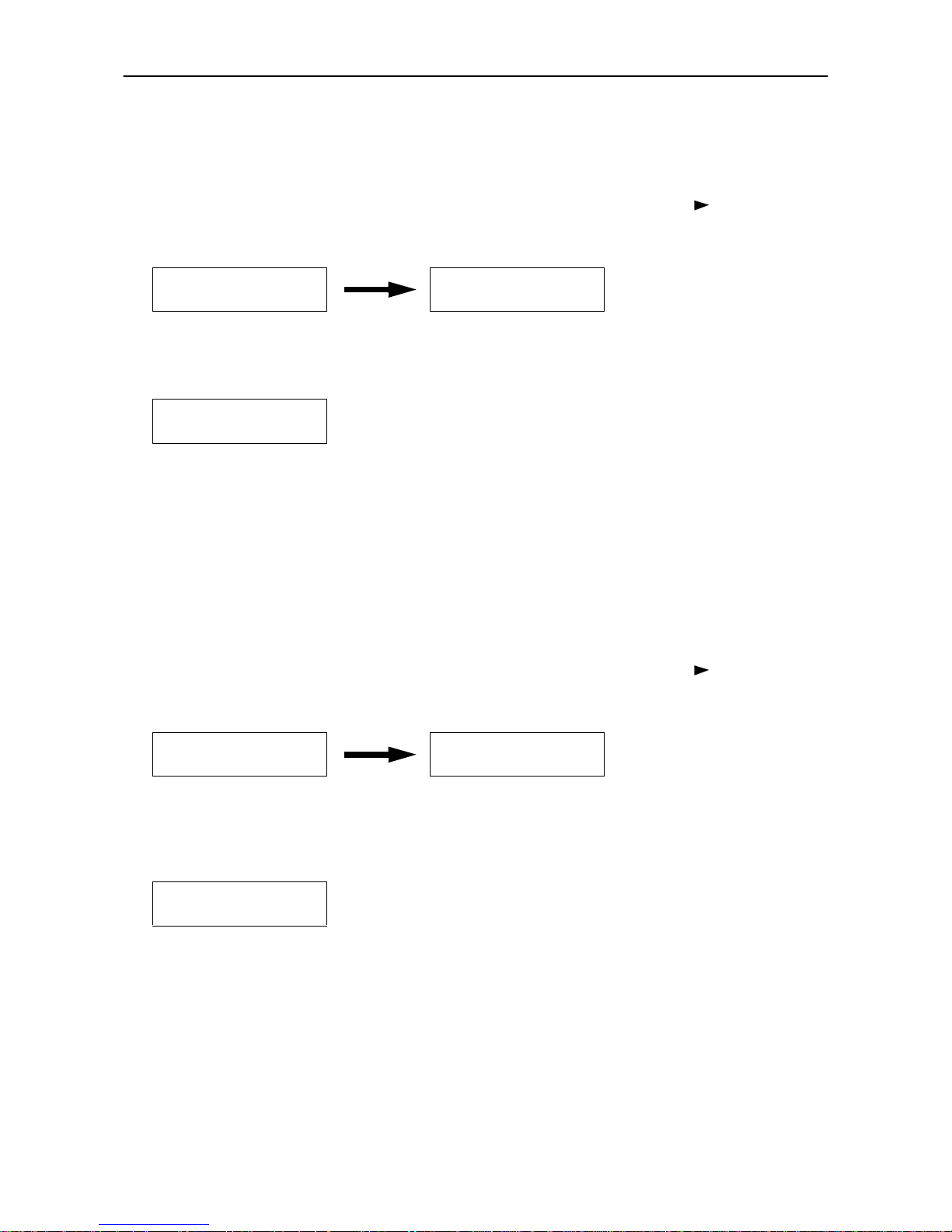
2.8. Setting the Paper Type
2-20
Making Settings
The following describes the procedure for setting the paper type using the Recycled type and Cassette as
examples.
1.
Display Paper handling > on the printer's Mode Select Menu and press the key. Then use the
+
and – keys to display the Cassette type.
2.
Pressing the
ENTER
key will cause a ? to flash. Press the + and – keys to display Recycled.
Press the
CANCEL
key if you want to cancel the setting. The ? display will disappear.
3.
Pressing the
ENTER
key will cause the ? to disappear. Pressing the
EXIT
key will exit the setting.
The same procedure can be used to set the paper type for other paper sources.
Paper Type User Setting
The following describes the procedure used to set a user-defined paper type for the printer. Eight custom user
settings may be registered. After having been set, any of these may be called up when setting the paper type
for a paper source.
1.
Display Paper handling > on the printer's Mode Select Menu and press the key. Then use the
+
and – keys to display >Type adjust.
2.
Pressing the
ENTER
key will cause a ? to be displayed. Press the + and – keys to select the paper type
(see page 2-19) that you want to customize and then press the
ENTER
key.
☛
Note that if you change the setting for a paper type other than
Custom 1
through 8 the paper
type setting for each paper source set to that paper type will be changed.
Paper handling > >Cassette type
Plain
>Cassette type
? Recycled
Paper handling > >Type adjust >
Custom #
>Type adjust
? Custom #
Page 69
2.8. Setting the Paper Type
2-21
3.
Press the key after selecting the paper type you want to customize. Pressing the + and – keys will
cycle through a display of the submenus given in the table below.
Display the submenu to be set and press the
ENTER
key. A ? will flash. Press the + and – keys to select
the desired parameter.
Press the
CANCEL
key if you want to cancel the setting. The ? will disappear.
4.
Pressing the
ENTER
key will cause the ? to disappear. Pressing the
EXIT
key will exit the setting.
The same procedure can be used to set the parameters on other submenus.
Note that the setting status for paper weight and fuser mode used for each paper type is as given in the table
below. In addition, all paper type settings made using Type adjust can be reset to the default values
shown in the table below using the >Reset type adjust menu.
*
: These cannot be selected when the paper source is EF-100.
**
: These paper types will cause slower printing when the paper is fed from the MP tray.
Submenus displayed Selection parameters Description
>>Paper weight Normal
(default)
Heavy (Thick)
Sets the paper thickness
>>Duplex path
(only when the paper type
is
Custom #
)
Enable
(default)
Disable
Selects duplex printing on/off when an optional
duplexer is installed (setting active only for the
selected paper type)
>>Paper weight
? Normal
(Example: Setup menu for Paper weight)
Paper Type
Plain
Trans-
parency*
Pre-
printed
Labels**
Bond
Recycled
Vellum*
Rough**
Letter-
head
Color**
Pre-
punched
Enve-
lope**
Card
stock**
Custom
Pap er
weight
Normal
O × OOOOOOOOOO × O
Heavy
(Thick)
× O ЧЧЧЧЧЧЧЧЧЧO ×
Page 70

2.9. Sleep Mode
2-22
2.9. Sleep Mode
The printer has a sleep timer to conserve power when the printer is not printing, processing, or receiving
data. You can adjust the timer value, the length of time the printer waits before entering sleeping mode in
the absence of data.
Any value from 0 to 120 [minutes] (the factory setting is 30 [minutes]) can be entered in 5-minute increments. You can use the or key to move the cursor back and forth through the figures to rapidly set a
large value.
If the printer receives no data for the period adjusted as above, it times out and enters into sleeping mode,
indicating Sleeping on the message display. When you send data for printing to the printer again or
press a key on the control panel, the printer starts warming up, indicating Please wait, and becomes
ready and on-line.
Opening and closing the printer's top cover or drawing out and closing the current paper cassette also awakens the printer to start warming up and become ready.
The printer also enters into sleeping mode if it times out while MODE SELECTing, or requesting the addition of paper or toner, indicating the appropriate maintenance message on its message display.
☛
The printer environment last set is still maintained even though all indicators are out while the
printer is in
Sleeping
mode.
Page 71

2.10. Dumping Received Data
2-23
2.10. Dumping Received Data
It is possible to print data received by the printer as hexadecimal code for the purposes of debugging programs and files.
1.
Pressing the
ENTER
key once while >Print HEX-DUMP is shown on the message display will cause
a ? to display.
2.
Pressing the
ENTER
key once again, Processing will be shown for a second then the message
Waiting will appear on the message display.
3.
Send data to be dumped to the printer. The message Processing will be displayed during receiving
the data. Once the dumped data you require has been output, it is possible to cancel the printing of any
further dumped data by taking the printer offline by pressing the
ON LINE
key and then pressing the
CANCEL
key.
4.
Once all data has been received, the message Waiting will appear. Press the
FORM FEED
key to finish
printing.
Page 72
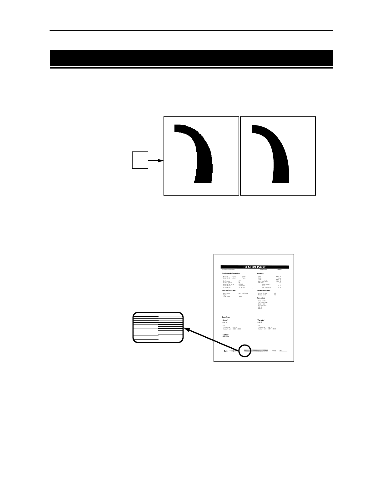
2.11. KIR 2 Level
2-24
2.11. KIR 2 Level
This printer incorporates the KIR 2 smoothing function. At resolutions of 600 dpi and 300 dpi, this function
provides high print quality by providing software enhancement of print resolution. The function does not
operate at 1200 dpi because that is the maximum resolution attainable by the print engine.). KIR 2 provides
high quality printing by providing a software-type improvement to the resolution.
☛
Set the print density to
03
when setting the KIR 2 mode. For details on print density, see
page 2-26
.
You can look at the check line, the last line on a status page, to make the optimum KIR 2 mode setting.
The KIR setting is
Off
. The KIR setting is
On
.
Q
Status Page
KIR Checking Lines
Page 73

2.12. Draft Mode
2-25
Optimized stripes
The current KIR setting is optimal.
Dark vertical stripes
Set the KIR mode to Off. Try printing the status page again. If you still get
dark vertical stripes, adjust the print density control to a lighter setting. (See
the last page in this manual.)
White vertical stripes
Set the KIR mode to On. Try printing the status page again. If you still get
white vertical stripes, adjust the print density control to a darker setting.
(See the last page in this manual.)
2.12. Draft Mode
The Draft enables you to reduce the amount of toner consumed on the page so as to save your printing costs.
You can set to Draft mode on, as follows. (The factory-setting is Off. )
The Draft mode setting is On when the printing image becomes lighter, yet very readable.
☛
The Draft setting has no effect on the print speed.
Draft setting is
Off
(default).
Draft setting is
On
Page 74

2.13. Resource Protection
2-26
2.13. Resource Protection
When you switch from the HP LaserJet emulation to another, all downloaded fonts and macros are lost.
Resource protection preserves these PCL resources in memory so that they are intact when you change the
emulation back to PCL 6.
By using the printer's MODE SELECT, you can select from two resource protection modes as follows:
>Resource prot.
Permanent
In this mode, the printer stores fonts, macros, symbol sets, etc. in memory that were downloaded as permanent PCL resources. All temporary resources are lost when the emulation mode is changed from PCL 6 to
another or vice versa.
>Resource prot.
Perm / Temp
In this mode, the printer stores both permanent and temporary resources when the emulation mode is
changed from PCL 6 to another or vice versa.
☛
Resource protection requires extra memory to store the downloaded fonts and macros. The total
size of the printer memory recommended for using the resource protection option is affected by
several factors. See section
1.7. Memory Expansion Installation
.
2.14. Adjusting the Print Density
If necessary, the print density can be adjusted from the MODE SELECT MENU. Density can be adjusted in
five steps from 01 (light) to 05 (dark). The factory setting is 03, and there is normally no need to alter this
setting.
When using the KIR function, please use the " 03" setting.
Page 75
2.15. Setting the Audio Warning (Buzzer)
2-27
2.15. Setting the Audio Warning (Buzzer)
In addition to the message displayed when the paper supply is exhausted, or when paper jamming occurs,
an audio warning is made to sound. This is useful, for example, when the printer is in a location some distance from the user.
The audio alarm is set to ON when leaving the factory. An audio alarm corresponding to the type of printer
error will sound according to the table below. If the alarm is set to OFF, it is made not to sound.
Type of Error and Corresponding Audio Alarm (Buzzer)
* Model DP-1800 only
** These error messages are displayed if the relevant option is fitted.
Priority Error Message
Alarm Frequency
Remarks
Short beeps: approx. 0.8 s
Long beeps: approx. 0.4 s
High
Replace Toner
Clean printr
short beeps —
Replace wastetoner bottle
short beeps —
Clean printer
Press CONTINUE
short beeps —
Paper jam
short beeps —
Face-down tray
paper full
short beeps *
Paper path error
short beeps **
Option stacker
paper full
short beeps **
Remove Opt.
Stacker paper
short beeps **
Load MP tray
short beeps —
Memory overflow
Press CONTINUE
short beeps —
Print overrun
Press CONTINUE
short beeps —
KPDL error
Press CONTINUE
short beeps —
MEMORYCARD err
Press CONTINUE
short beeps **
RAM DISK error
Press CONTINUE
short beeps —
Opt. ROM error
Press CONTINUE
short beeps **
Set paper
Press CONTINUE
short beeps —
Load Cassette
short beeps —
Low
Add paper
long beeps —
Page 76

2.15. Setting the Audio Warning (Buzzer)
2-28
The alarm will continue to sound while the error condition continues (if the printer is in the sleep mode, the
alarm will be silent for that period alone). The alarm will cease to sound, however, when the
CANCEL
key is
pressed.
To rectify the various error conditions listed above, please refer to Chapter 5 of this manual, or to the operating manuals accompanying the various optional equipment.
☛
!
If you wish to cancel the data being processed while the audio alarm is sounding, press the CANCEL key twice. Firstly, the audio alarm will be turned OFF, and then the data processing will be
canceled.
!
After the audio alarm has been set to OFF, even if the PRESCRIBE 2e FRPO INIT command is executed, the printer will not return to the initial (ON) alarm setting. To set the audio alarm to ON,
reset using the mode selector menu from the control panel.
Page 77

3.1. Internal Fonts
3-1
Chapter 3
Fonts
This chapter describes the types of fonts you can use with the printer, including the
printer's internal fonts.
3.1. Internal Fonts
A font is a set of characters of a particular design. The design is referred to as a typeface. Several character-
istics identify a font. These include the code set, spacing, pitch, height, style, stroke weight, and typeface
family.
The printer has 80 PCL/PS compatible fonts and a bitmap font for a line printer loaded into it. Also fonts may
be downloaded to the printer's memory from a memory card or disk. These fonts are referred to as downloadable or soft fonts. The printer accepts as many downloadable fonts as its user available memory permits.
Page 78
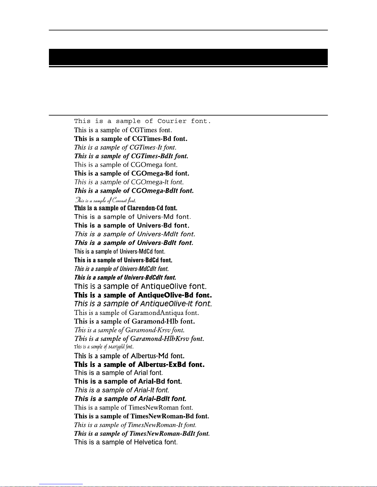
3.2. List of Fonts
3-2
3.2. List of Fonts
This section contains a full list of the pr inter's internal fonts. You can print th e same font list from the printer
by using the printer's control panel key. To print a list of fonts, refer to Mode Select Menu, List of fonts.
Internal Scalable and Bitmap Fonts
Font
number Font samples
0
1
2
3
4
5
6
7
8
9
10
11
12
13
14
15
16
17
18
19
20
21
22
23
24
25
26
27
28
29
30
31
32
33
34
35
36
37
Page 79
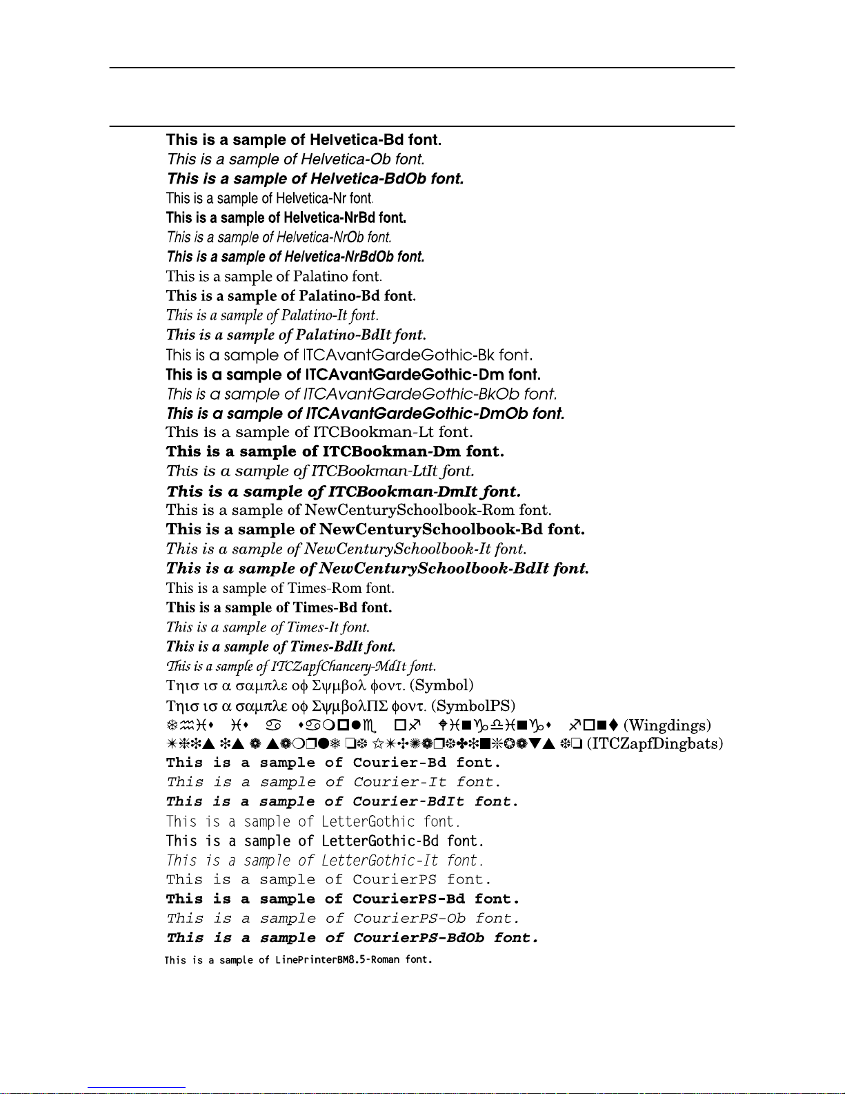
3.2. List of Fonts
3-3
Font
number Font samples
38
39
40
41
42
43
44
45
46
47
48
49
50
51
52
53
54
55
56
57
58
59
60
61
62
63
64
65
66
67
68
69
70
71
72
73
74
75
76
77
78
79
80
Page 80
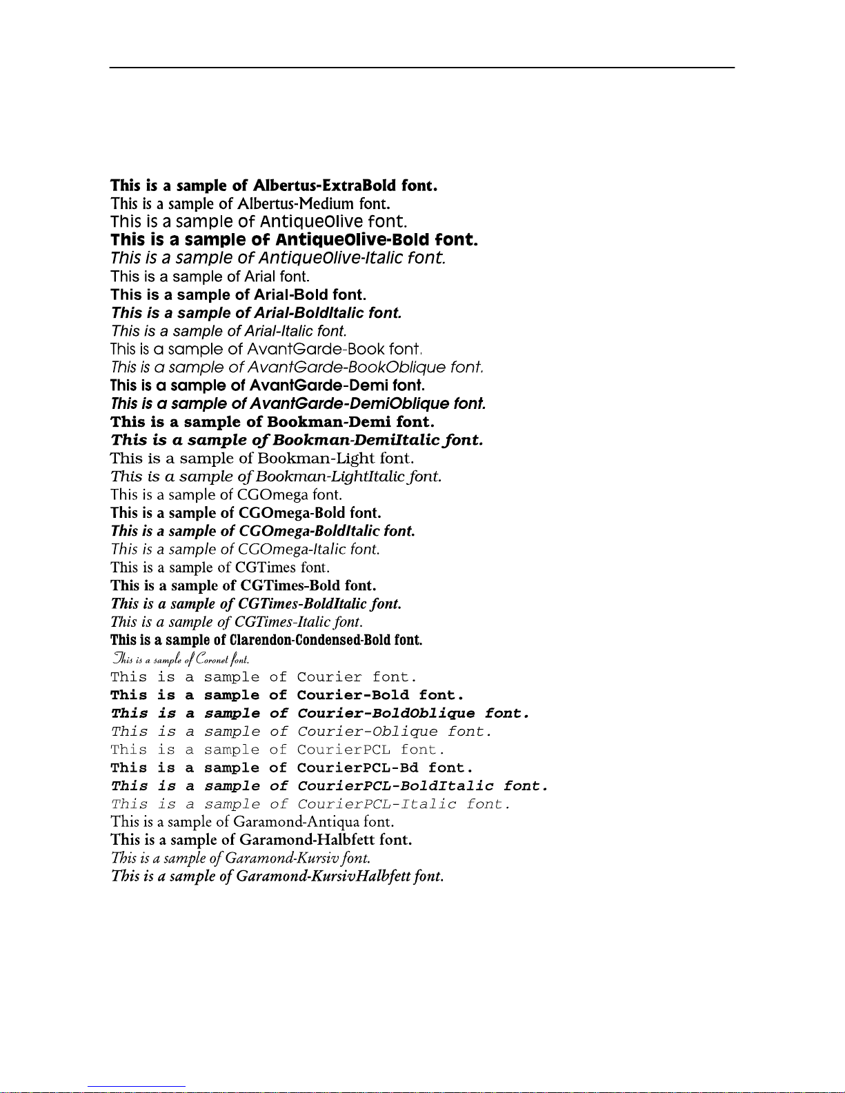
3.2. List of Fonts
3-4
KPDL Fonts (1)
Page 81
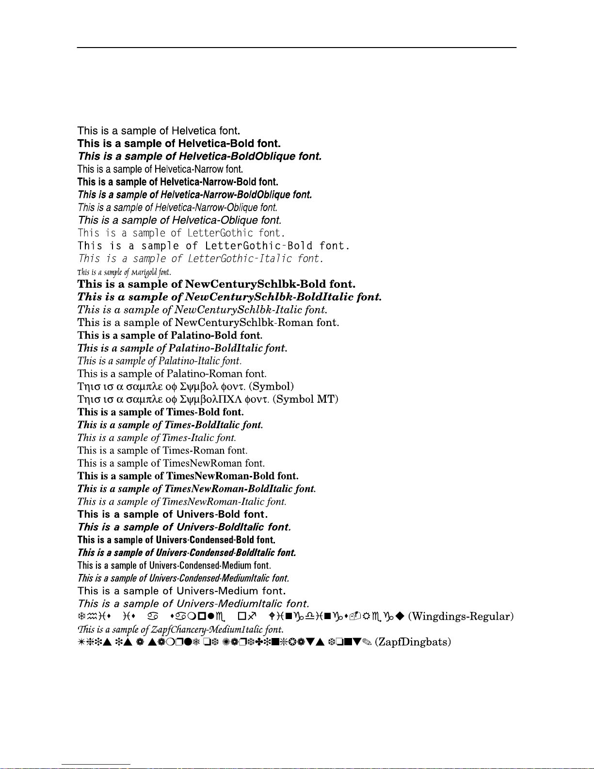
3.2. List of Fonts
3-5
KPDL Fonts (2)
Page 82

This page is intentionally left blank
Page 83
4.1. Toner Kit Replacement
4-1
Chapter 4
Maintenance
This printer is designed to provide years of trouble-free service without the necessity
of printer module replacement. However, you must replace the toner container in the
printer with a replacement container from a new toner kit. Also, to ensure good print
quality, various parts inside the printer must be cleaned at regular intervals.
4.1. Toner Kit Replacement
The toner container in the printer should be replaced as soon as the message display shows
Toner low Clean printer or soon after. If you continue to use the printer, eventually the toner
supply will be exhausted at which point the printer will stop printing and the
Replace Toner Clean printer message will be shown instructing you to install a new toner kit.
Toner kit replacement interval
The life of the toner container will vary according to the density of print in your documents. If you print documents with an actual toner coverage of approximately 5% (with the Ecoprint mode* turned off), the toner
container will need replacing approximately once every 10,000** pages (20,000 pages with the BT-2000).
* Turning the Ecoprint mode ON conserves toner. Refer to Chapter 2 for details.
** In the case of a new printer in which a tone r kit has been installed for the first time, the number of pages that can be printed will be 6,000.
Toner Kit to be Used
The toner kit to be used with this printer is the BT-2000. It contains the following:
❒ Toner container
❒ Waste toner bottle
❒ Wiper (lint-free) cloth
❒ Grid cleaner
❒ 2 plastic bags (for disposal of the old toner container and waste toner bottle)
❒ Instructions
(The kit supplied with the printer contains only the toner container and waste toner bottle.)
☛
We strongly recommend you use only the original toner kit. Use of the original toner assures the
intended long term reliability of the printer.
CAUTION
Do not incinerate toner and toner containers. Dan gerous sparks may cause burn.
Page 84
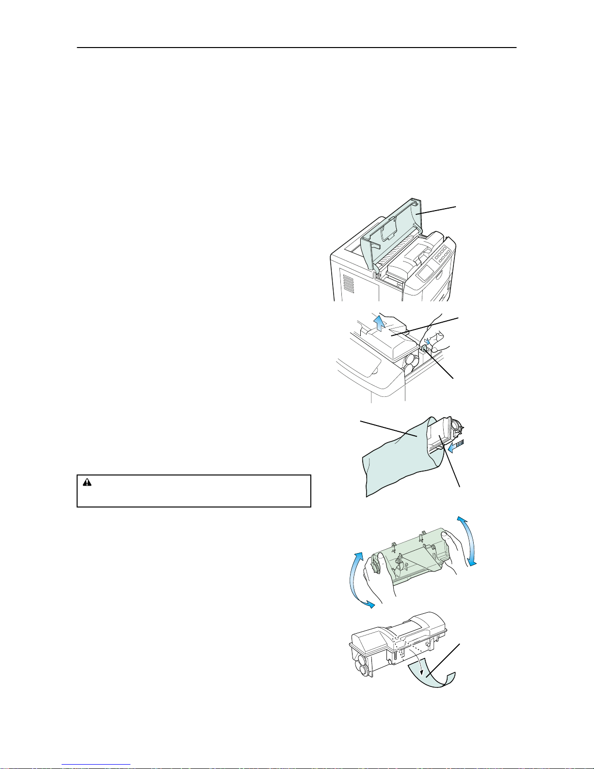
4.1. Toner Kit Replacement
4-2
Supplying Toner
☛
Before proceeding, take note of the following:
! Do not leave floppy disks etc. lying around while performing this maintenance procedure. This
procedure tends to raise a little toner dust which can harm magnetic recording media.
! Do not attempt to reuse the waste toner remaining in the toner container.
! Use only the toner kit exclusively designed for the printer. Use of a toner kit intended for use with
other printer models may damage the printer and void the warranty.
To replace the toner container, proceed as follows.
1.
Open the printer's top cover all the way.
2.
Press the toner container release lever (Green) to
release the old toner container from the printer.
Remove the old toner container as gently as possible.
☛
Keep the toner container as level as possible while
removing.
3.
Put the old toner container in the plastic bag supplied with the toner kit. Dispose of the toner container.
☛
The old toner container may be incinerated without the risk of generating harmful gas.
4.
Take the new toner container from its bag.
With the label side down, thoroughly shake the toner
container (in the direction of the arrow) ten times or
more to loosen and mix the toner inside.
5.
The bottom of the toner container is sealed with a
plastic strip. Carefully pull the sealing strip off the
toner container, making sure not to leak any toner.
Dispose of the sealing strip.
CAUTION
Do not incinerate toner and toner containers. Dangerou s sparks
may cause burn.
To p Co ve r
Old Toner
Container
Toner Container
Release Lever (Green)
Old Toner Container
Plastic Bag
New Toner Container
Sealing Strip
Page 85
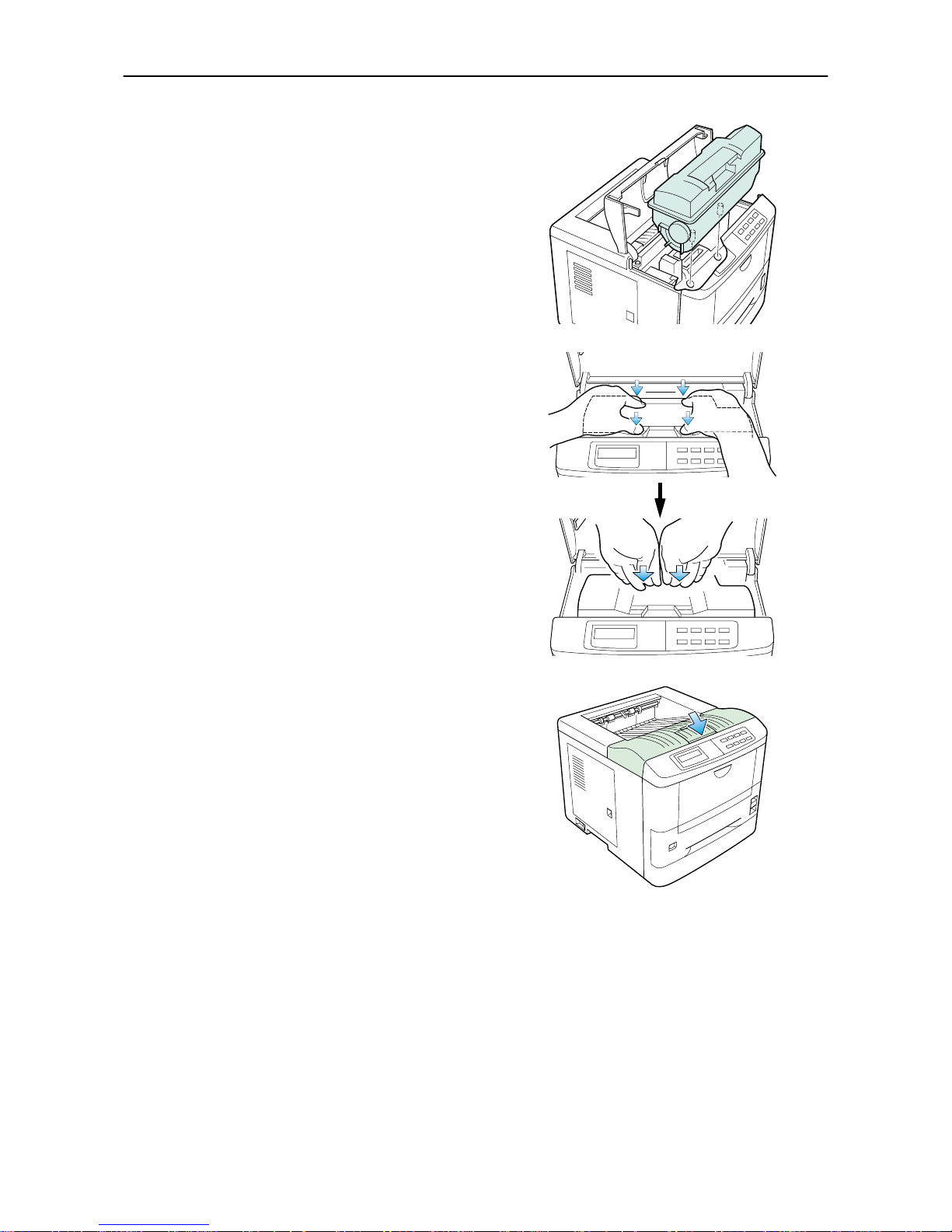
4.1. Toner Kit Replacement
4-3
6.
Install the toner container on the developer as shown
in the diagram.
☛
Be sure to peel off the seal on the toner container
before mounting the toner container on the developer unit.
7.
When the toner container is installed correctly on
the developer.
8.
Push the top of the toner container unit ("PUSH HERE")
until it locks in.
☛
Make sure that the toner container is properly
locked in the printer.
9.
Close the top cover by pressing the arrowed part in
this diagram.
☛
It is necessary to clean the inside of the printer
after replacing the toner container.
If the toner container is replaced when the message Replace Toner Clean printer is displayed, the message Clean printer Press CONTINUE will be displayed after replacement.
After cleaning the inside of the printer (See Section
4.2. Cleaning
), the message will disappear when
the CONTINUE key is pressed, and the printer will be ready for printing.
Page 86
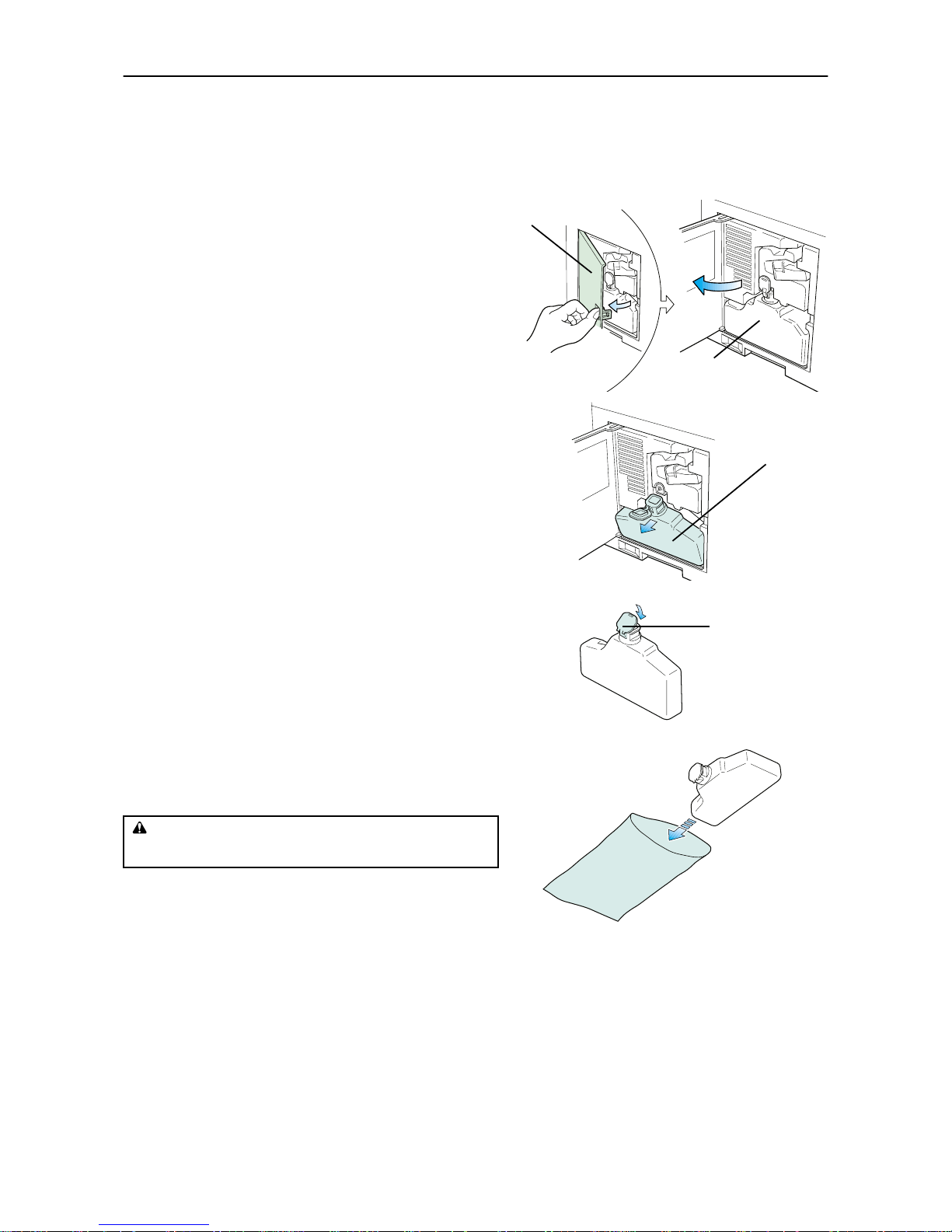
4.1. Toner Kit Replacement
4-4
Replace the Waste Toner Bottle
☛
When replacing the toner container, the used waste toner bottle in the printer should also be
replaced with a new one from the new toner kit.
1.
Open the printer side cover.
2.
Remove the waste toner bottle as shown right.
☛
Remove the waste toner bottle as gently as possible so as not to scatter the waste toner inside. Do
not let the opening of the waste toner bottle face
downward.
3.
Cap the waste toner bottle after removing from the
printer.
4.
To avoid toner spilling, place the capped waste toner
bottle in the plastic bag supplied before forwarding
to proper disposal.
CAUTION
Do not incinerate toner and toner containers. Dangerou s sparks
may cause burn.
Side Cover
Old Waste
Toner Bottle
Old Waste
Toner Bottle
Old Waste
Toner Bottle
Cap
Plastic Bag
Page 87
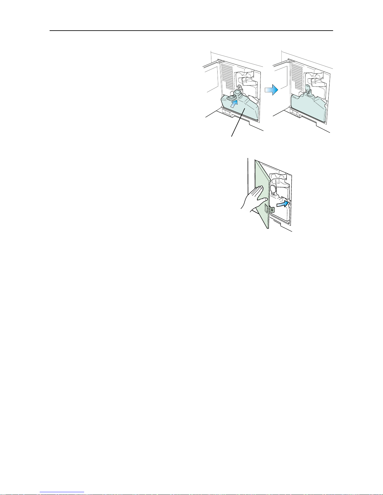
4.1. Toner Kit Replacement
4-5
5.
Locate the new waste toner bottle in the toner kit,
and install in the printer as shown right.
☛
Do not cap the new waste toner bottle.
Insert the new waste toner bottle with the bottle
tilted slightly towards you as shown in the figure.
6.
After ensuring that the bottle is correctly installed,
close the side cover.
New Waste Toner Bottle
Page 88
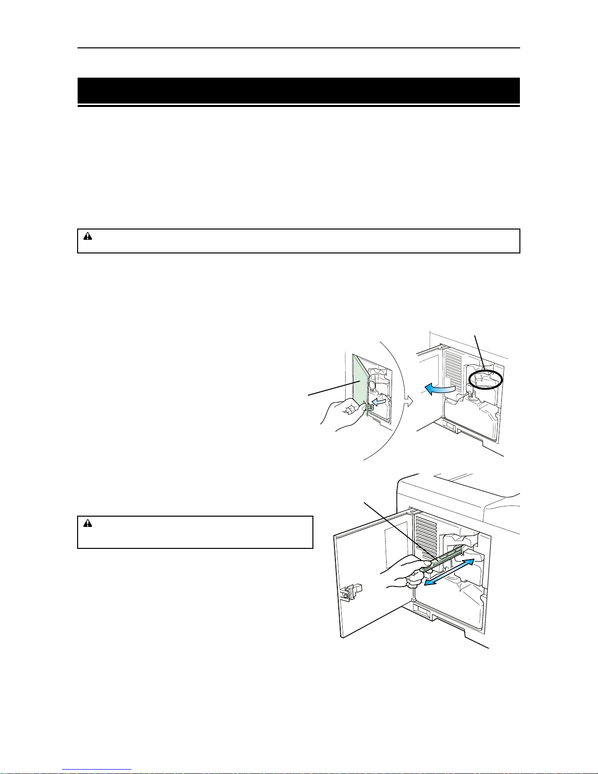
4.2. Cleaning
4-6
4.2. Cleaning
In addition to the maintenance procedures described on the following pages, the charger wire in the drum
unit and paper feed unit should be cleaned from time to time, or whenever print quality problems occur.
To avoid print quality problems, the following printer parts must be cleaned with every toner container
replacement.
☛
If the toner container has been replaced when the message Replace Toner
Clean printer was displayed, the message Clean printer Press CONTINUE will be
displayed after replacement. After cleaning the inside of the printer following the procedure shown
below, press the CONTINUE key; the message will disappear and the printer will be ready for printing.
Main Charger Unit
The main charger unit grid should be cleaned when the toner container is changed.
Cleaning the Charger Wire
1.
Open the printer side cover.
2.
Pull the cleaning knob (Green) slowly in and out a
few times. This pulls a cleaning pad inside the drum
unit along the wire.
CAUTION
For safety purpose, ALWA YS remove the power p lug from the ou tlet when perform ing cleaning ope rations.
CAUTION
Do not incinerate toner and toner containers. Dangerou s sparks
may cause burn.
Main Charger Unit
Side Cover
Cleaning Knob
(Green)
Page 89
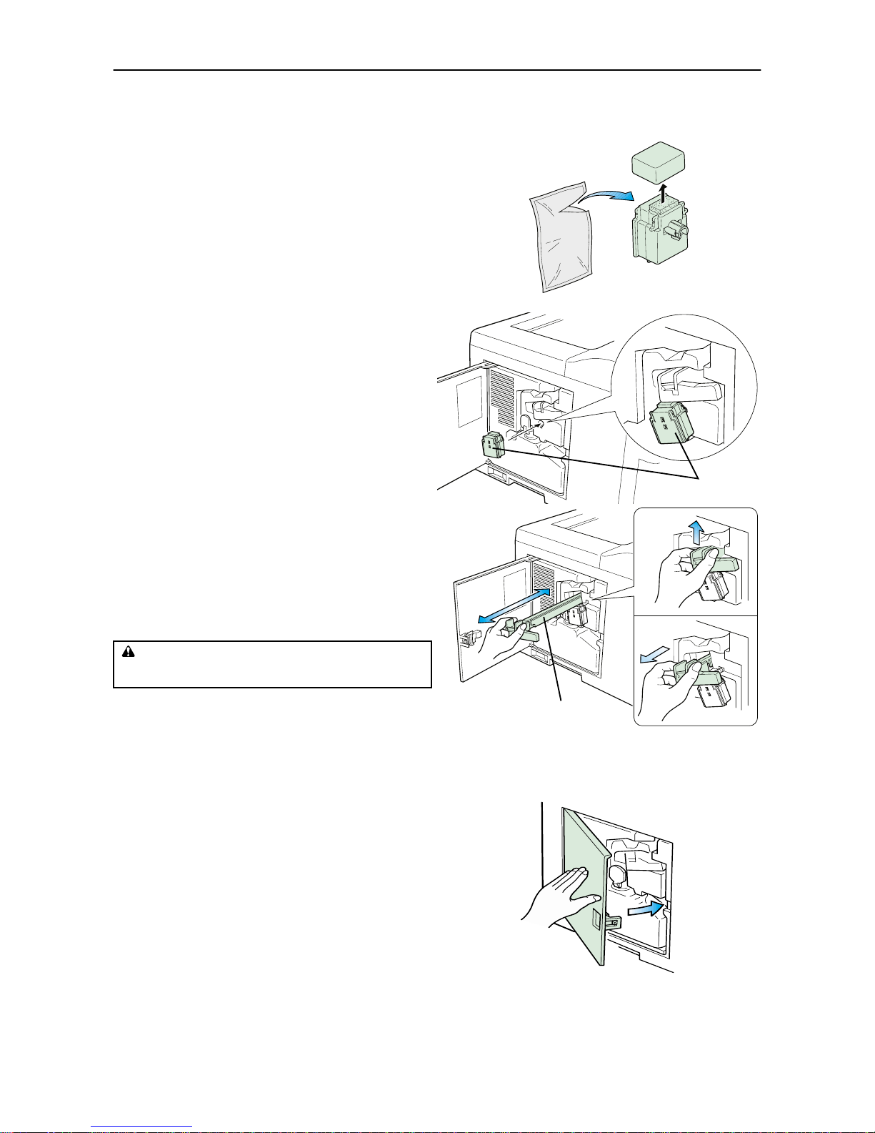
4.2. Cleaning
4-7
Cleaning the Grid
1.
Take the grid cleaner from protective bag in the new
toner kit, and remove the cap.
☛
The grid cleaner pad is impregnated with water.
Perform the following cleaning procedure before
the pad dries.
2.
Attach the grid cleaner to the printer with the pad
uppermost, as shown in the diagram.
3.
After attaching the grid cleaner, repeat the action
of slowly pulling out and then pushing back in the
main charger unit at least 5 times. It is easier to
pull out the main charger for the first time if it is
raised slightly, as shown in the figure.
The grid part underneath the main charger is
cleaned by this procedure.
4.
When the grid is clean, remove the grid cleaner
from the printer and dispose of it. The grid
cleaner is not re-usable.
5.
After cleaning the charger wire, push the cleaning knob all the way in and close the side cover.
WARNING
For safety purpose, ALWAYS remov e the power plug fr om
the outlet when c leaning the m ain charger .
Protective Bag
Cap
Grid Cleaner
Grid Cleaner
Main Charger Unit
(1)
(2)
(3)
Page 90
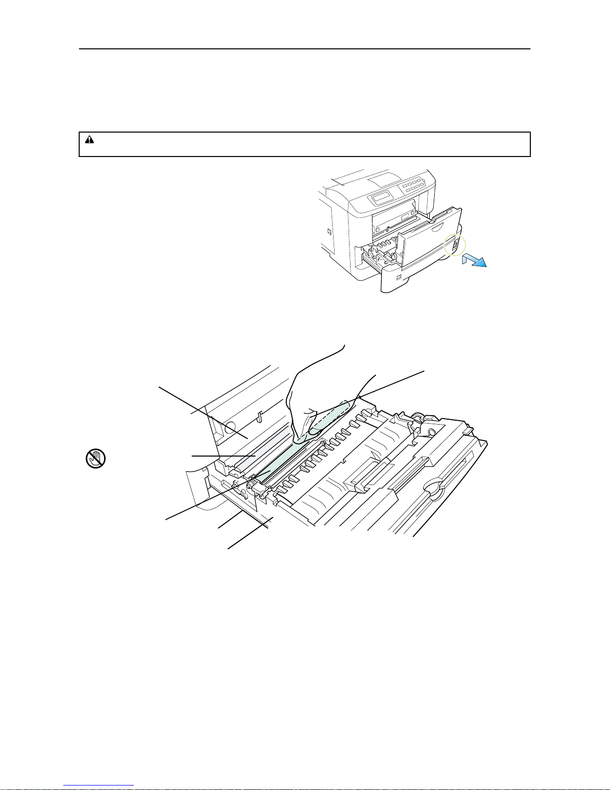
4.2. Cleaning
4-8
Paper Feed Unit
To avoid print quality problems due to paper dust and debris, clean the paper feed unit in the following manner.
1.
Pull the paper feed unit release lev er up and draw
the paper feed unit all the way out until it stops.
2.
Wipe the paper dust on the registration roller and the paper ramp using the wiper cloth included in the
toner kit.
☛
Do not touch the transfer roller (the black roller) when wiping the paper ramp.
CAUTION
For safety purpose, ALWA YS remove the power p lug from the ou tlet when perform ing cleaning ope rations.
Paper Feed
Unit Release
Lever
Paper Ramp
Transfer Roller
[Black]
Registration Roller
Paper Fe ed Unit
Wiper Cloth
Page 91

5.1. General Guide
5-1
Chapter 5
Troubleshooting
This chapter explains how to handle printer problems which may or may not occur. The
procedures are easy to follow. If a problem persists after you have completed the
appropriate troubleshooting procedures, call for the assistance of a service person.
5.1. General Guide
If the printer does not print
If nothing is displayed on the message display on the front control panel, then you probably have a power
problem. See section 5.2.
If the printing is abnormal
With the printer on-line and ready, press the STATUS key to print a status page. You can also optimize print
quality using the KIR test pattern printed at the bottom of the status page. To adjust the print status, see
Chapter 2.
❒ If the result is normal, you may have an interface problem. See section 5.3.
❒ If the result is not normal, you have a print quality problem. See section 5.4.
If a maintenance message is displayed on the message display:
❒ See section 5.5. (For a paper jam, see section 5.6.)
If the printer does not print the entire page or indicates Memory overflow on its message display, try
adding optional memory. To add optional memory, see Chapter 1.
Page 92

5.2. Power Problems
5-2
5.2. Power Problems
☛
The printer power rating must be within the voltage range in your country. If in doubt, consult your
dealer.
If nothing happens when you switch the printer's power on, you have a power problem. The symptoms are a
dark control panel, no printing, and no fan sound. Proceed as follows.
Check the power switch.
The on position is marked "|".
The off position is marked "O".
Check the power cord.
If the cord is loose at either end, switch power off, plug the power cord in securely, then switch power on again.
Call for the assistance of a service person.
If the above checks do not solve the problem, call for the assistance of a service person.
5.3. Interface Problems
If the printer prints a status page correctly but does not print data from the computer correctly (or at all),
there may be an interface problem.
Check the interface (network) cable.
Make sure the cable is plugged in securely at both ends.
Check your file and software.
Try printing a different file, or using a different print command.
Try using a different cable.
Compare the pin assignments listed in Appendix C with the specifications of your cable.
Call for the assistance of a service person.
If the above checks do not solve the problem, call for the assistance of a service person.
Page 93

5.4. Print Quality Problems
5-3
5.4. Print Quality Problems
Print quality problems range from uneven tone to completely blank output. The troubleshooting procedure
for each type of problem is given below.
If the checks explained in this section do not solve the problem, call for the assistance of a service person.
Completely blank printout
Check the developer unit.
Open the printer top cover and check that the developer unit is inserted correctly and check that the developer 's connector is connected properly.
Call for the assistance of a service person.
All-black printout
Check the Main Charger Unit
Open the printer side cover and check that the main charger unit is correctly installed.
Call for the assistance of a service person.
Page 94
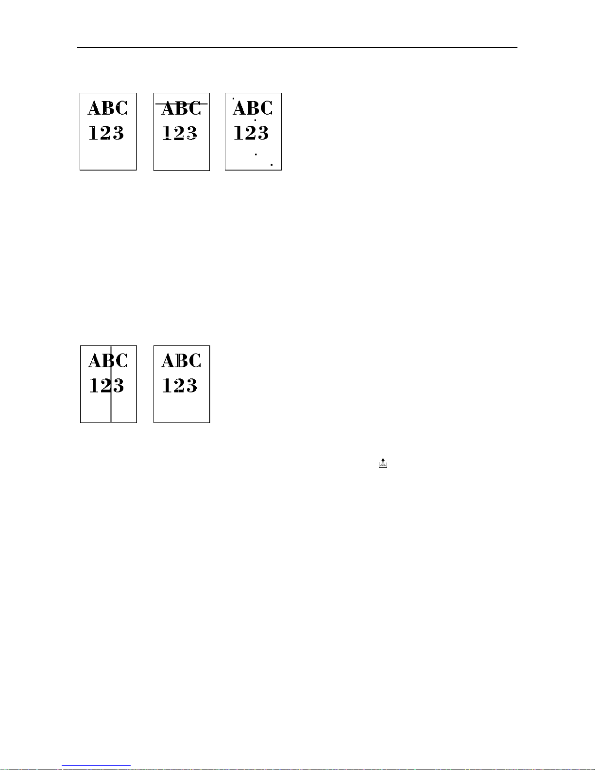
5.4. Print Quality Problems
5-4
Dropouts, horizontal streaks, stray dots
Clean the charger wire.
Open the printer side cover. Pull the green main charger wire cleaning knob slowly in and out a few times.
See Section 4.2.
Note the spacing of the defects.
If the defects occur at regular intervals of 60.6 mm (2.4 inches), the problem may be a dirty transfer roller.
Call for the assistance of a service person.
If the defects occur at regular intervals of 94 mm (3.7 inches), the problem may be a damaged drum unit or
fuser roller. Call for the assistance of a service person.
Black or white vertical streaks
Check the control panel.
If the Toner low Clean printer message is displayed and the indicator is flashing, install a
new toner kit. See Section 4.1.
Clean the charger wire.
Open the printer side cover. Pull the green main charger wire cleaning knob slowly in and out a few times.
See Section 4.2.
Call for the assistance of a service person.
If the above checks do not solve the problem, call for the assistance of a service person.
Page 95
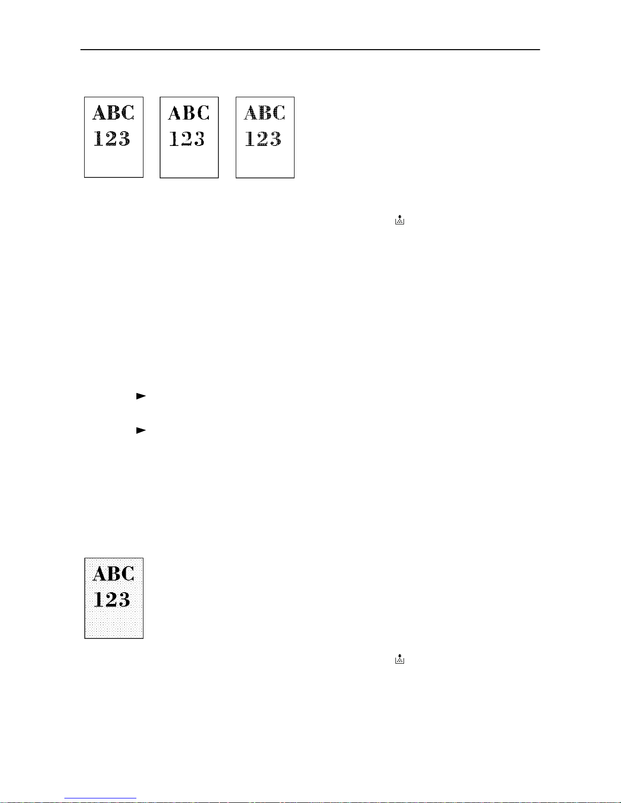
5.4. Print Quality Problems
5-5
Faint or blurred printing
Check the control panel.
If the Toner low Clean printer message is displayed and the indicator is flashing, install a
new toner kit. See Section 4.1.
Set the print density from the control panel to a higher level than the current setting. See Section 2.14.
Make sure the Paper Type setting is correct.
Check the Draft setting.
See Section 2.12.
Cleaning the drum surface
To clean the drum surface, proceed as follows.
1. Press the
MODE
key.
2. Press the + or
-
key repeatedly until the message display indicates >Others.
3. Press the
key.
4. Press the + or
-
key repeatedly until the message display indicates >Sevice >.
5. Press the
key.
6. Press the + and
-
keys to display >>Drum.
7. Pressing the ENTER key will cause? to be displayed.
8. Press the ENTER key. The drum then starts turning and stops after approx. 3minutes.
The printer then reverts to Ready.
Grey background
Check the control panel.
If the Toner low Clean printer message is displayed and the indicator is flashing, install a
new toner kit. See Section 4.1.
Check the print density.
Display the print density menu from the control panel and select a lighter density setting. See Section 2.14.
Page 96
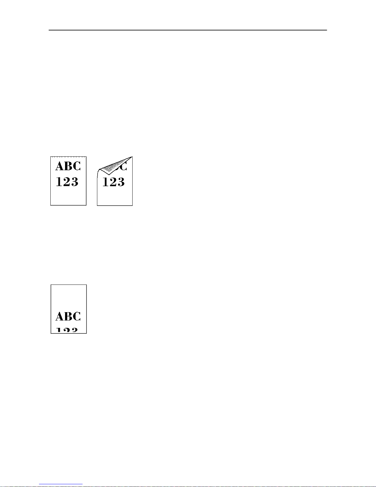
5.4. Print Quality Problems
5-6
Clean the main charger wire.
Open the printer's side cover. Pull the green main charger wire cleaning knob slowly in and out a few times.
See Section 4.2.
Check the main charger unit installation.
Open the printer's side cover. Remove the main charger unit half way out, then reinstall it properly. See section 4.2.
Call for the assistance of a service person.
If the above checks do not solve the problem, call for the assistance of a service person.
Dirt on the top edge or back of the paper
Check the paper chute and the ramp.
Draw out the paper feed unit and check for toner on the paper ramp. Clean the paper ramp (see Section 4.2.)
using the wiper supplied, or a soft, dry, lint-free cloth.
Check the transfer roller.
If the transfer roller is dirty with toner, try printing several pages; or call for the assistance of a service person.
Characters out of position
Check the file or program.
See if the problem is caused by incorrect PRESCRIBE 2e commands. If the problem occurs with only one file
or program, the most likely cause is a command error.
Call for the assistance of a service person.
If the above checks do not solve the problem, call for the assistance of a service person.
Page 97
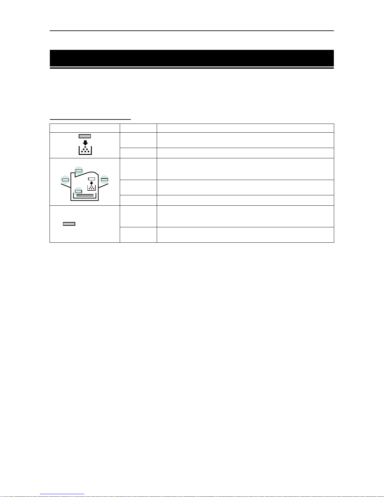
5.5 Indicators and Messages
5-7
5.5 Indicators and Messages
The tables on the following pages indicate how to respond to problems indicated by the control panel symbolic indicators and messages.
Indicators
Table 5.1 Symbolic Indicators
Indicator Condition Corrective Action
Flashing
The printer has run low on toner. The toner should be replaced as soon
as possible.
Lit
Install a new toner kit. See Section 4.1.(Toner Empty)
Fast
Flashing
There is a paper jam. There is a possibility that paper may be jammed at
the point indicated by flashing, open and remove any jammed paper. See
Section 5.6.
Slow
Flashing
The paper has run out in the paper cassette or MP tray. Please insert
paper. See Section 1.4.
Lit
This indicates either the current paper feeder or the paper output point.
ATT ENTION
Flashing
The printer has insufficient memory available or the printer is warming
up (
Please wait
). Confirm the message indicated on the message
display. See Section 5.5.
Lit
Note the maintenance message on the message display and consult
Table 5.2.
Page 98
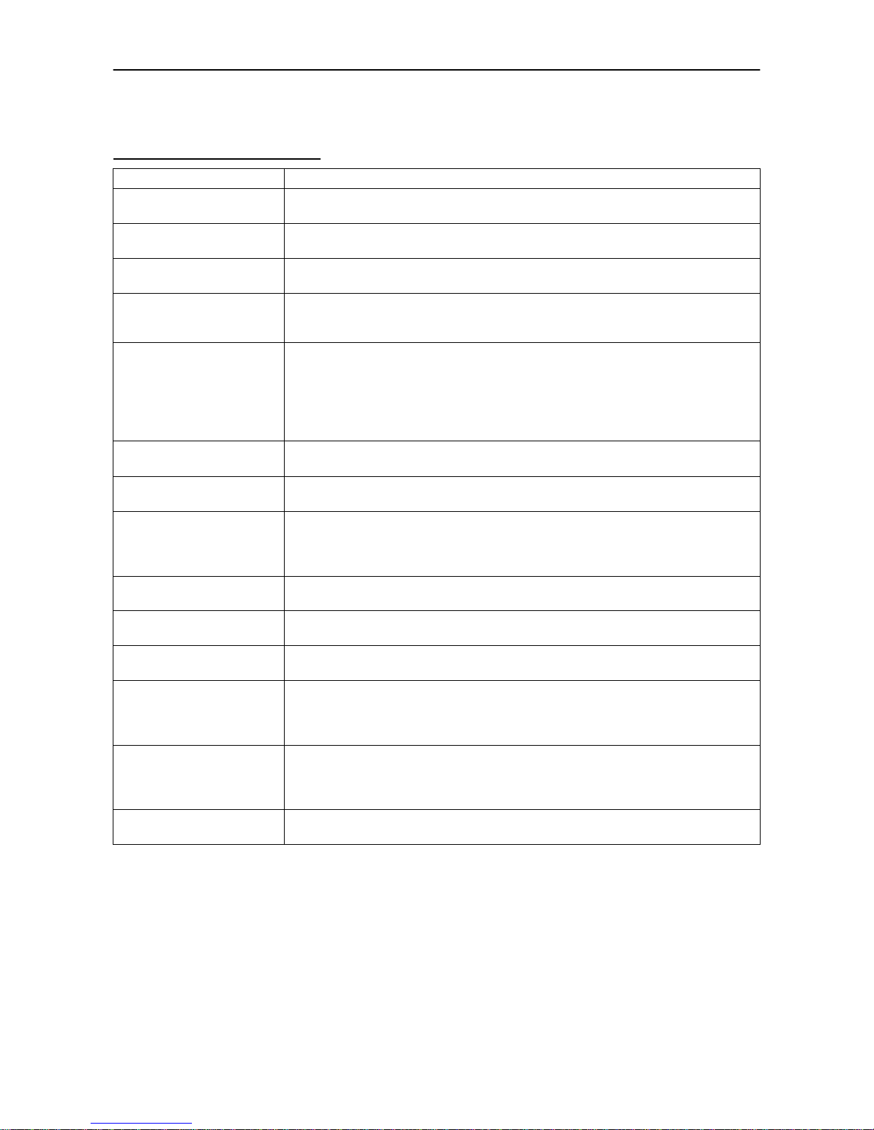
5.5 Indicators and Messages
5-8
Maintenance Messages
Table 5.2 Maintenance Messages
Message Corrective Action
Top cover
Open
Open the top cover, then close tightly.
Side cover
Open
Open the side cover, then close tightly.
Paper feed unit
Open
Open the paper feed unit, then close tightly.
Face-down tray
paper full
The face-down tray has become full (approx. 250 pages). You must remove all printed
pages from the face-down tray. When the printer senses that the face-down tray is
empty again, it will continues printing into the face-down tray (Model DP-1800 only).
Add paper
(paper source)
(paper size)/(paper type)
*(paper size) and (paper
type) are displayed flashing
alternately.
The paper has run out. Supply paper according to the paper source displayed (paper
cassette, MP tray, or optional paper feeder).
Set paper
Press CONTINUE
Add a sheet of paper to the MP tray, and press the CONTINUE key.
Paper jam
Open the top cover or the paper feed unit and correct the paper jam (or paper mis-feeding in the cassette). See Section 5.6.
Warning
Low memory
The printer's internal memory is running low due to the number of fonts and macros
downloaded. Print a status page to see how much user memory is left, and try deleting
unnecessary fonts and macros. See the PRESCRIBE 2e DELF and DELM commands
explanation in the programming manual (CD-ROM).
Option interface
Error
A failure has occurred with the option interface.
Check the option interface installed on the printer.
Toner low
Clean printer
Replace the toner container using a new toner kit. See Section 4.1.
Replace Toner
Clean printer
Replace the toner container using a new toner kit. The printer does not operate when
this message is displayed. See section 4.1.
Clean printer
Press CONTINUE
Please clean the inside of the printer. See Section 4.2.
This message will be displayed when replacing the toner container after the message
Replace Toner Clean printer
has been displayed. After cleaning the
inside of the printer, press the CONTINUE key and the printer will be ready for printing.
Replace Wastetoner bottle
Replace the old waste toner bottle with the new one which is included in the BT-2000
toner kit. The mess age will also be shown if the waste t oner bottle has become full. T he
waste toner bottle should be replaced when the message display eventually shows
Toner low Clean printer
. See Section 4.1.
Missing Wastetoner bottle
Install the waste toner bottle. See Section 1.4. The printer does not operate when this
message is displayed.
Page 99
5.5 Indicators and Messages
5-9
Load Cassette #
(paper size)/(paper type)
*(paper size) and (paper
type) are displayed flashing
alternately.
There is data for printing that matches with a paper cassette s etting (paper size, paper
type), but there is no paper in the cassette.
Set paper into the paper source as displayed on the control panel, and press the
CONTINUE key to restart printing. However, the paper source number (#) is only dis-
played when there is an optional paper feeder installed.
Or, i f you want to print from a different paper source press the FEED key to display
Use
alternative?
and you can change the source for paper feeding. Further, you can
change the paper source by pressing the FEED key.
After selecting a paper source and pressing the MODE key,
Paper handling >
appears. By pressing the key, the paper type settings menu appears. After setting
the correct paper type, press the EXIT key and printing starts.
Load MP tray
(paper size)/(paper type)
*(paper size) and (paper
type) are displayed flashing
alternately.
There is no paper cassette set (paper size, paper type) that matches with the data for
printing .
Because there is no cassette that matches the data, printing is done from the MP tray.
Set paper into the MP tray that matches the paper size and type shown on the display
and press the CONTINUE button to restart printing.
Or, i f you want to print from a different paper source press the FEED key to display
Use
alternative?
and you can change the source for paper feeding. Further, you can
change the paper source by pressing the FEED key.
After selecting a paper source and pressing the MODE key,
Paper handling >
appears. By pressing the key, the paper type settings menu appears. After setting
the correct paper type, press the EXIT key and printing starts.
Call service
personEn:0123456
Mechanical error (n=0, 1, 2, ...)-Call a service person. The printer does not operate
when a message beginning with E is displayed. The total number of pages printed is
also indicated.
Call service
personFn:0123456
Controller error (n=0, 1, 2, ...)-Call a service person. The printer does not operate
when a message beginning with F is displayed. The total number of pages printed is
also indicated.
Message Corrective Action
Page 100
5.5 Indicators and Messages
5-10
Error Messages
Table 5.3 Error Messages
Message Corrective Action
Memory overflow
Press CONTINUE
The total amount of data received by the printer exceeds the printer's internal memory. Try adding more memory (expansion RAM). Press the CONTINUE key to resume
printing. You can abandon printing by the CANCEL key.
Print overrun
Press CONTINUE
The data transferred to the printer was too complex to print on a page. Press the
CONTINUE key to resum e printin g. (Th e page ma y break in some pag es. )
You can abandon printing by the CANCEL key.
Note:
After this message has been displayed, Page protect mode will be On. To
maintain optimum use of memory during printing, display
>Page protect
from the control panel, and re-select
Auto
.
See the last page in this manual.
KPDL Error
Press CONTINUE
Current print processing cannot continue.
To print out a error report, display
> Print KPDL errs
from the mode select
menu, and select
On
.
Press the CONTINUE key to resume printing. You can abandon printing by the CANCEL
key.
RAM DISK error ##
Press CONTINUE
Check the error code displayed in the place of
##
and refer to the appropriate descrip-
tion below.
01
:Abnormal format. Try turning the power off and on again.
02
:RAM DISK mode is
Off
. Turn RAM DISK mode
On
.
03
:Cannot write to the disk system because it is write protected. Remove the write
protection.
04
:No disk space. Clean up files.
05
:Specified file not on disk.
06
:No memory for use by disk system. Expand printer memory.
10
:Cannot format disk because host data is spooled there. Format the disk after
Ready
is displayed.
98
:Unable to read files during the sorting (file does not exist, or corrupted).
MEMORY CARD err
Insert again
The memory card is accidentally removed from the printer's memory card slot during
reading. If you continue reading the memory card, insert the same memory card into
the slot again. The printer again reads it from the beginning of the data.
Note: We recommend that you follow the reading procedure from the beginning to ensure correct reading of the memory card.
Insert the same
MEMORY CARD
You have inserted the wrong memory card when the
Insert again
message was
displayed. Remove the wrong memory card from the printer's memory card slot and
insert the correct memory card. The printer again reads it from the beginning of the
data.
Format error
MEMORY CARD
This message appears when the printer is in the ready state and the memory card is
not formatted, and therefore cannot be read or written. Follow the procedure on Section 2.6. to format the card.
Warning battery
MEMORY CARD
This message appears when the printer is in the ready state and the battery in the
memory card is low. You can still enter the memory card mode, but the battery should
be changed as soon as possible.
Battery error
MEMORY CARD
This message appears when the printer is in the ready state and the battery in the
me mory ca rd is de ad, or t here is no ba ttery at all. It is not possib le to u se the me mory
card mode until you insert a good battery in the card.
 Loading...