

Page 1
MIT
Music Interface Technologies
™
®
4130 Citrus Avenue, Suite 9, Rocklin, CA 95677 916/ 625-0129 Fax: 916/ 625-0149 www.mitcables.com
The
Vero HCA•29 and HCA•50ex
Headphone Amplifiers are the
world’s first high current, battery powered Class A/ B headphone
amps housed with MIT’s Multipole™ Technology.
Until now, MIT’s Multipole
Technology has only been
housed within the little
“boxes” found on all of MIT
Cables’ award-winning products. For the first time ever,
MIT is integrating this technology inside an amplifier.
MIT Cables’ core audio cable
technology is our exclusive
Poles of Articulation (Multipole),
named after the fact that every
audio cable has a single point
where it is most efficient at
storing and transporting energy.
At this point in the audio frequency spectrum, the cable
will articulate best, and represents the cables’ particular
Articulation Pole.
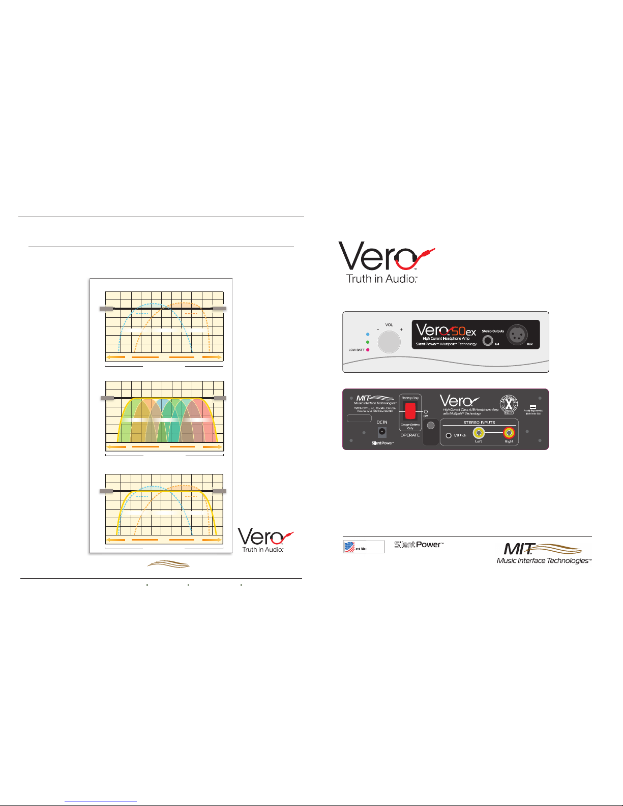
About the Graphs: The
graphs at right are conceptual
illustrations representing the
bandwidth of the audible range
of the human ear. We use
these graphs to illustrate how
well a cable articulates across
this bandwidth. The 50% line
serves as our baseline for
ideal articulation response.
If a cable is over-articulating
(above the 50% line) , it's
sound might be described as
“harsh”, or “brittle.” If a cable
is under-articulating, it will be
perceived as lacking “detail”,
or “garbled”.
Graph A:
shows the bandwidth of two Competitor's
audio cables as tested in the
MIT laboratory. Cable 1 has
its Articulation Pole tuned to
a lower frequency, and would
be described by audiophiles
as “muddy” or “veiled.” Cable
2 has its Articulation Pole tuned to a high frequency, and would be
described by audiophiles as “bright” or “fast.” Additionally, both cables
have areas of “over-articulation” as shown in their respective shaded
areas.
Graph B:
This graph illustrates one of MIT's popular
interfaces with 6 Poles of
Articulation. MIT 's interfaces
are engineered to have multiple
Articulation Poles optimized for
the lows, mids, and highs. Our
Poles of Articulation synergistically work together to transport
the audio signal with a more
even response than just a single cable, as if multiple cables
are being used together. Poles
A & B provide an area of better
bass, Poles C & D provide an
area of better midrange, and
Poles E & F provide an area of
better highs.
Graph C:
This plot directly
compares MIT's 6-pole
interface (yellow line) to the
Competitor's Cables from
Graph A. MIT's interface
provides a linear articulation
response, resulting in a more
controlled bass, and smoother,
more extended highs along
with a lower noise floor –“like
multiple cables in one!”
When choosing an interface, look for the Multipole
Technology logo with the performance rating indicating the
number of Poles of Articulation
in each product. This simple
feature will help you select the
correct performance level for
any system, with complete confidence and accuracy.
MIT–Competitor’s Cables Comparison
60
50
40
30
20
10
0
-10
Articulation (%)
Audible Range of the Human Ear
IDEAL
50
50
IDEAL
50
BASS MIDRANGE TREBLE
Competitor’s
Cable 1
Competitor’s
Cable 2
Area of Over Articulation
Area of Over Articulation
Over-Articulating
Under-Articulating
Ideal Articulation
Area of Better Bass Area of Better HighsArea of Better Midrange
C
Competitor’s Cables
60
50
40
30
20
10
0
-10
Articulation (%)
BASS MIDRANGE TREBLE
IDEAL
50
50
IDEAL
50
Audible Range of the Human Ear
Competitor’s
Cable 1
Competitor’s
Cable 2
Area of Over Articulation
Area of Over Articulation
Over-Articulating
Under-Articulating
Ideal Articulation
Area of Better Bass Area of Better HighsArea of Better Midrange
A
60
50
40
30
20
10
0
-10
Articulation (%)
BASS MIDRANGE TREBLE
Area of Better Bass Area of Better HighsArea of Better Midrange
MIT 6-Pole Interface
Audible Range of the Human Ear
IDEAL
50
50
IDEAL
50
Over-Articulating
Under-Articulating
Ideal Articulation
B
A B C D E F
MIT Multipole™ Technology Explained
©2017 CVTL, I nc. All rights reserved; D oc: Vero HA instruction b ro; 12/2017
MIT
Music Interface Technologies
™
®
by
H/L
GAIN
ON
STANDBY
High Current, Class A/B Headphone Amplifiers with Multipole™ Technology
Proudly Engineered
and Made in the USA
Proudly Engineered
and Made in the USA
and Ma
de
Proudly Engineered
and Made in the USA
by
Vero 50ex Operation Manual
Page 2

Operating Instructions for your
Vero
™
Series Headphone Amplifier
High Current, Class A/B Headphone Amps with Multipole
™
Technology
Please follow these steps to “initialize”
the charging circuit prior
to operating your new
Vero Series Headphone
Amplifier.
Before any use, please begin by
turning the volume control knob
full left counter clockwise to protect
your ears, and disconnect the headphones. This procedure will protect you
from unexpectedly high volume levels at
start up. From there, please proceed :
1. Plug the charger into a convenient wall out-
let from 100V AC to 230V AC. The LED on the
charger will glow green indicating it is now powered (Fig. B). Inser t the DC barrel connector to the
“DC in” port, on the rear panel (Fig. C).
2. Rock the switch on the rear panel to the bottom or
“Charge Battery Only” position (Fig. C) - The LED on the
charger will now glow red if the battery is not 100% charged (Fig.
A). (U pon reaching full charge it turns from Red to Green. Red
means it is charging. Green means it has reached full charge.)
3. Rock the switch one click further to the center position, marked
“OFF” (Fig. D) . This is “STANDBY” position and the Green LED on
the front panel should glow brightly (Fig. DD).
4. Rock the switch to the next position at the top (Fig. E). This
is “On” and the Blue LED on the front panel should glow brightly.
(Fig. EE)
5. Now that the initializing process is complete, set the rocker
switch back to the starting “Charge Battery Only” position (Fig. C).
If the LED on the charger is Red, you may elect to leave it there
until it reaches 100% and glows Green.
6. Unplug the charger, connect your input source (1/8” or stereo
RCA), check the volume control and switch the amp to the Battery
Only position (Fig. E) . The Blue LED will glow and the amplifier is in
full operation mode (Fig. EE).
NOTE: Y
ou may need to repeat this process should the Vero
amp not be used for extended periods of time. When the
charging circuit sees an extended period without operation, a
protection circuit is enabled, and the unit may appear to be nonresponsive. This feature is designed to prevent the unnecessar y
discharge of the Lithium Ion batteries to zero. For battery details
and specifications, please refer to the Samsung Data Sheet
included. (N o. ICR18650 -26F)
Charger Lights–
• Red light indicates unit is
being charged.
• Green light indicates unit is
fully charged and can operate
in battery mode. Charging
cable can now be safely
disconnected from unit.
Charging Mode–
To recharge unit, connect
charging cable into “DC
In” and depress switch into
“Charge Battery Only”
position. Lights on the
charger will indicate status.
(Figs A & B)
Low Battery Indicator–
Light marked “Low Batt” will light up, indicating unit needs
recharging (Fig. CC ). Reconnect charging cable until green
light appears indicating the unit is charged. (Fig B)
Quick Start—Your Vero
™
Series Headphone Amplifier
A
Battery Operation–
When Charger indicates a full charge by displaying a green light (Fig. B), charging cord may be
disconnected and red switch (Fig. C) placed into up
position labeled “Battery Only” (Fig. E) for normal
operation. The front panel blue light indicating the
unit is “On” will be lit (Fig. EE).
Plunger switch to cut gain (and noise floor) by 50%
The High/Low gain switch is for use with low impedance high sensitivity headphones to reduce circuit noise.
Engineers agree that the way to optimize the listener experience and expectation is to install a plunger switch
on the back of the unit to select Low, or High Gain. This feature cuts the power in half, and therefore cuts
circuit noise in half. Most importantly, this noise is detectable only when music is not playing and does not
negatively alter or diminish the musical experience.
E
EE
C
C
B
Standby Operation–
Position the red switch in the center “Off” position
when the unit is not in use (Fig. D). The front panel
green “Standby” indicator light will be lit (Fig. DD ).
D
DD
CC
 Loading...