

MISUMI DS102MS, MSCTL102, MCSTL102-MS, MSCTL102-IO-MS, DS102MS-IO Operation Manual
...
Stepping Motor Controller
MSCTL102 Series/MSCTL112 Series Operation Manual
Ver 1.01 (02.13.2015)
Remarks
MSCTL102/112 Series(MISUMI products) are same as DS102/112 Series that are made by Suruga Seiki.
All of DS102/112 series that are mentioned in the operation manual indicate MSCTL102/112.
MISUMI CO., LTD.
SURUGA SEIKI CO., LTD.

2
Index
1.INTRODUCTION ................................................................................................................................................................................. 5
1.1 FOR YOUR SAFETY .............................................................................................................................................................................. 5
1.2 PRODUCT OUTLINE / FEATURES ................................................................................................................................................... 7
1.3 SYSTEM CONFIGURATION EXAMPLE .............................................................................................................................................. 9
1.3.1 CONTROL WITH PLC................................................................................................................................................................. 9
1.3.2 CONTROLLED BY PC ............................................................................................................................................................. 10
1.4 ACCESSORIES .................................................................................................................................................................................... 11
2.SET-UP AND EXAMPLE OF USE ................................................................................................................................ 11
2.1 SET UP BEFORE USE ....................................................................................................................................................................... 11
2.1.1 CONNECTING ............................................................................................................................................................................ 12
2.1.2 USB DRIVER INSTALL ......................................................................................................................................................... 15
2.1.3 INSTALLATION FOR CONTROL SOFTWARE DS102/112(DSCONTROL-WIN) ..................................... 19
2.1.4 ADJUSTMENT SYSTEM PARAMETER ............................................................................................................................... 23
2.1.5 OPERATION CHECK ................................................................................................................................................................ 25
2.2 SYSTEM ARCHITECTURE ............................................................................................................................................................... 27
2.2.1 MOVEMENT BETWEEN EACH TEACHING POSITION..................................................................................................... 27
2.2.2 EASY RETURN TO ORIGIN POSITION .................................................................................................................................. 34
2.2.3 CONTROL BY EXTERNAL SIGNAL ...................................................................................................................................... 43
2.2.4 EXTERNAL DEVICE CONTROL WITH GENERALI/O. ................................................................................................. 54
2.2.5 MOVE TO ARBITRARY COORDINATE ................................................................................................................................ 56
2.2.6 CONTROLLED OVER 3 AXES .............................................................................................................................................. 58
3.SPEC AND FUNCTION........................................................................................................................................................... 59
3.1 BASIC SPEC ...................................................................................................................................................................................... 59
3.2 PART NAME AND FUNCTIONS ..................................................................................................................................................... 60
3.3 SETTING .................................................................................................................................................................................................. 63
3.4 EXTERNAL INTERFACE ...................................................................................................................................................................... 64
3.4.1 LINK CONNECTION(LINK) ................................................................................................................................................... 64
3.4.2 CONTROL INPUT/OUTPUT(CNT-I/O) ........................................................................................................................ 65
3.4.3 GENERAL I/O(I/O)( OPTION) ........................................................................................................................................ 68
3.4.4 EMERGENCY STOP INPUT(EMS) .................................................................................................................................... 70
3.4.5 STAGE INTERFACE ..................................................................................................................................................................... 70
3.5 DRIVER DIVISION NUMBER SETTING .............................................................................................................................................. 71
3.5.1 OPEN AND SHUT ........................................................................................................................................................................ 71
3.5.2 SETTING DIVISION NUMBER ..................................................................................................................................................... 71
3.6 SMOOTH DRIVE FUNCTION(ONLY MS TYPE) ...................................................................................................................... 72
3.7 UNITS SETTING FUNCTION ............................................................................................................................................................... 73
3.8 SPEED SETTING(SPEED TABLE) .............................................................................................................................................. 74
3.9 FUNCTION OF ORIGIN RETURN ........................................................................................................................................................ 77
3.10 LINEAR INTERPOLATING FUNCTION ........................................................................................................................................... 83
3.10.1 LINEAR INTERPOLATING(RELATIVE VALUE) ........................................................................................................... 83
3.10.2 LINEAR INTERPOLATING(ABSOLUTE VALUE) ........................................................................................................ 83
3.11 TEACHING FUNCTION ..................................................................................................................................................................... 84
3.12 PROGRAM FUNCTION ..................................................................................................................................................................... 84

3
4.OPERATION AND CONTROL METHOD .................................................................................................................. 85
4.1 OPERATION BY THE HANDY TERMINAL ...................................................................................................................................... 85
4.1.1 INITIAL SCREEN ............................................................................................................................................................................ 85
4.1.2 TRANSITION MODE ..................................................................................................................................................................... 86
4.1.3 DRIVING MODE SELECT(JOG KEY) ............................................................................................................................. 87
4.1.3.1 CONTINUOUS DRIVING MODE(CNT:CONTINUE MODE) ............................................................................ 87
4.1.3.2 UNIFORM PULSE DRIVING MODE(STP: STEP MODE) ................................................................................ 87
4.1.3.3 ABSOLUTE VALUE DRIVING MODE(ABS: ABSOLUTE MODE) ............................................................... 88
4.1.3.4 ORIGIN RETURN MODE(ORG: ORIGIN MODE) ............................................................................................... 88
4.1.3.5 HOME POSITION RETURN MODE(HOM:HOME) .......................................................................................... 88
4.1.4 MENU SELECT(MENU KEY) .............................................................................................................................................. 89
4.1.4.1 PARAMETER MODE(PRM) ....................................................................................................................................... 89
4.1.4.2 PROGRAM DRIVING MODE(PRG) ......................................................................................................................... 98
4.1.4.3 TEACHING MODE (TCH) ......................................................................................................................................... 99
4.1.4.4 GENERAL MONITOR(IN) ....................................................................................................................................... 102
4.1.4.5 GENERAL OUTPUT CONTROL(OUT) .............................................................................................................. 102
4.1.5 OTHER FUNCTION .................................................................................................................................................................. 103
4.1.5.1 CHANGE THE SPEED TABLE(SPD KEY)....................................................................................................... 103
4.1.5.2 CHANGE THE AXIS(LINK KEY) ............................................................................................................................ 103
4.1.5.3 CHANGES CURRENT POSITION(POS KEY) ................................................................................................... 103
4.1.5.4 VERSION CONFIRMATION, PARAMETER RESET .................................................................................................. 104
4.2 DS102/112 CONTROLLED SOFTWARE(DSCONTROL-WIN) ...................................................................... 105
4.2.1 DSCONTROL-WIN START-UP ................................................................................................................................... 105
4.2.2 PARAMETER SET-UP ............................................................................................................................................................ 105
4.2.3 JOG DRIVING ............................................................................................................................................................................. 107
4.2.4 TEACHING ................................................................................................................................................................................. 110
4.2.5 DRIVING PROGRAM ................................................................................................................................................................ 112
4.2.6 I/O MONITOR ..................................................................................................................................................................... 118
4.3 USER PROGRAM PROCESSING ................................................................................................................................................... 119
4.3.1 RS232C ................................................................................................................................................................................ 119
4.3.2 USB ........................................................................................................................................................................................... 120
4.3.3 DELIMITER .................................................................................................................................................................................. 122
4.3.4 TYPES OF COMMUNICATION COMMAND ........................................................................................................................ 123
4.3.5 DETAILS OF COMMUNICATION COMMAND .................................................................................................................. 135
4.3.5.1 AXIS SPECIFICATION COMMAND .............................................................................................................................. 135
4.3.5.2 PARAMETER SETTING COMMAND ........................................................................................................................... 135
4.3.5.3 MEMORY SW SETTING COMMAND........................................................................................................................ 139
4.3.5.4 SPEED TABLE SETTING COMMAND ...................................................................................................................... 140
4.3.5.5 WRITE COMMAND ......................................................................................................................................................... 141
4.3.5.6 DRIVING COMMAND ...................................................................................................................................................... 141
4.3.5.7 STOP COMMAND ........................................................................................................................................................... 142
4.3.5.8 PARAMETER SETTING REQUEST COMMAND .................................................................................................... 143
4.3.5.9 MEMORY SW SETTING REQUEST COMMAND .................................................................................................. 145
4.3.5.10 SPEED TABLE SETTING REQUEST COMMAND .............................................................................................. 147
4.3.5.11 STATUS REQUEST COMMAND............................................................................................................................. 147
4.3.5.12 GENERAL I/O COMMAND ....................................................................................................................................... 152
4.3.6 PROGRAM DRIVING DEDICATED COMMAND ............................................................................................................... 153
4.3.7 ERROR CODE ........................................................................................................................................................................... 156

4
5.CHECKOUT ..................................................................................................................................................................................... 157
6.FAULT DIAGNOSIS AND SOLUTION ...................................................................................................................... 157
7.WARRANTY & CUSTOMER SERVICE.................................................................................................................... 158
● APPENDIX ............................................................................................................................................................................................... 159
■ DIP SWITCH SET ............................................................................................................................................................................................. 159
■ DS102 EXTERNALS .................................................................................................................................................................................... 160
■ DS112 EXTERNALS .................................................................................................................................................................................... 161
■ CONTROL I/O CABLE(MODEL:DS100-CNT-2) ............................................................................................................... 162
■ GENERAL I/O CABLE(MODEL:DS100-IO-2) ................................................................................................................... 163
■ SELECTION OF A PROGRAM NUMBER BY CNT-IO ........................................................................................................................ 164
■ SELECTION OF A TEACHING NUMBER BY CNT-IO ........................................................................................................................ 164
5
Cautions
!
1.INTRODUCTION
Thank you for purchasing this series Stepping Motor Controller.
1.1 For Your Safety
For Proper use, please read this operation manual thoroughly prior to using this product.
means the PROHIBITATION.
Please look after instructions shown here by all means.
Failure to use controller, may be hurt or suffer material damage.
・Basic cautions
・ Connect a power cable to a power outlet which comes with protective earth terminal, In case of
using an extension cable without protective earth terminal, protective earth will be of no effect.
・Cable
・When you unplug a power cable, turn off a power switch.
・When it supplies DS112 Series with a power supply, please be careful not to make a mistake in
polarity.
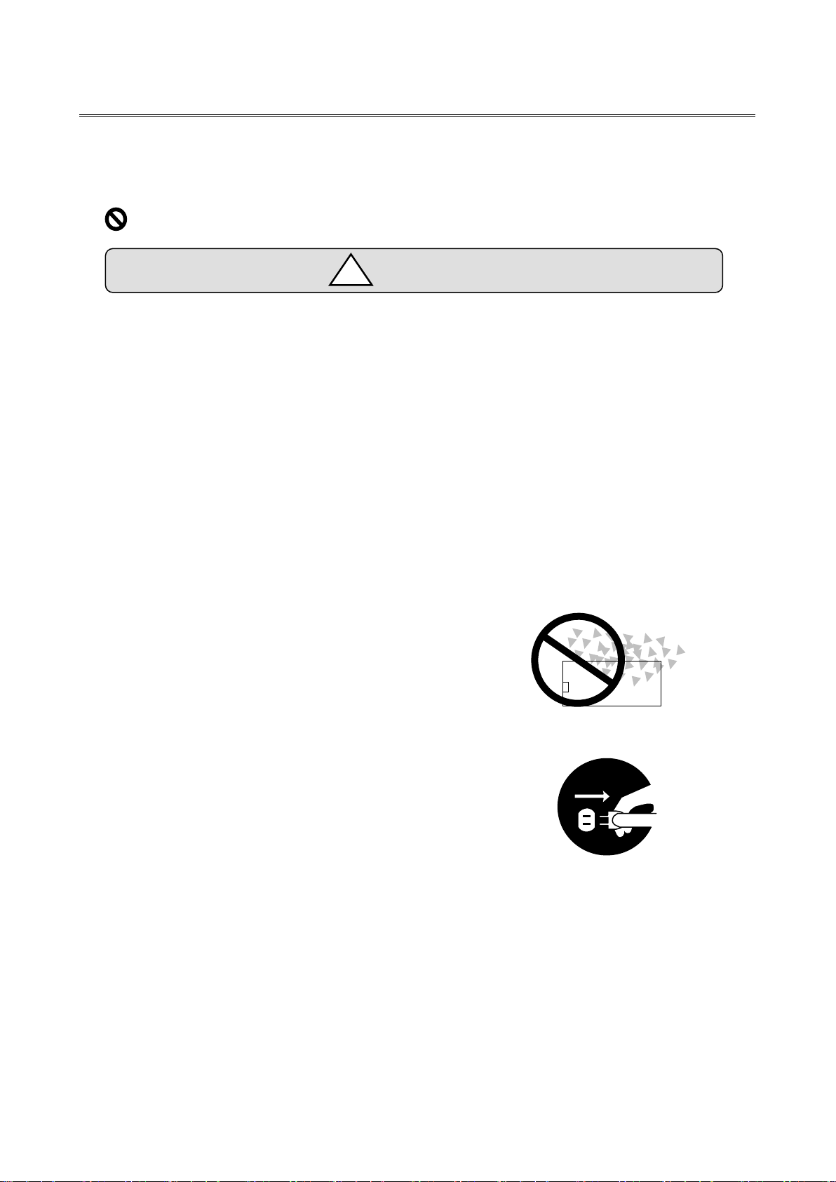
・Operating Environment
・To avoid as follows.:
-Areas that have much dust or metallic particles
-Directly under sunlight
-Near fire
-Much vibration
-Watery or oily place
-Wonky place
-Place with Corrosive Gas and Flammable Gas
・Storage
Please unplug a power from the outlet when
It doesn’t use for a long time, and you move this product..
A fire and the accident of the electric shock etc. are prevented.
6
Caution
!
・Power Source
・Please DO NOT connect the DS102 series besides the power supply outlet of interchange 100~
240V (AC100~240V 50/60Hz)
・Please supply direct 24V(DC24V±10%)power supply for DS112 series.
In order to avoid damage to controller, DO NOT use any input voltage or frequency over
the specifications.
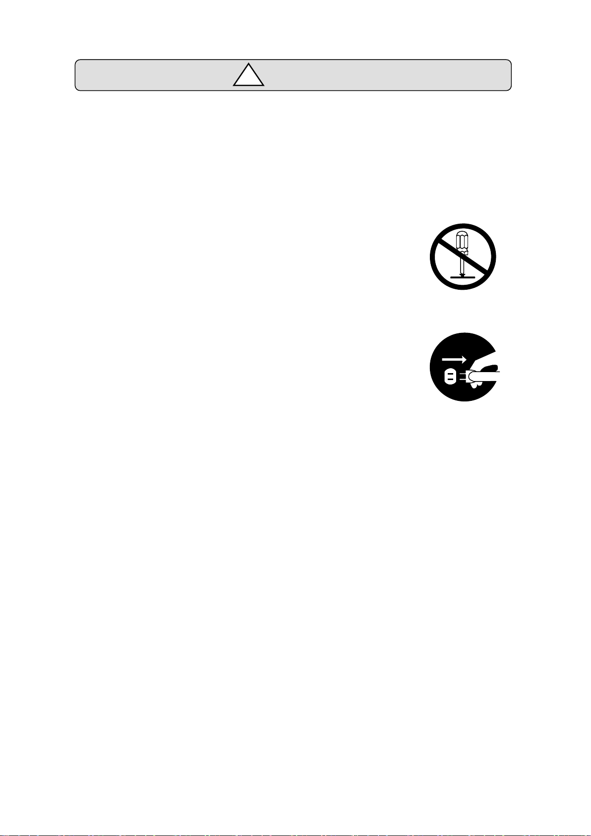
・Resolution of the product/Remodeling
・ Please DO NOT perform the resolution of the product, remodeling, the
unfair repair.
・ Please contact us for correct information if needed.
・Repair Service
・ In the case of the following, please disconnect the plug promptly and then
contact your supplier.
-When there are some strange sound, smelling and smoke.
-When a power supply cable damaged.
-When spilled water on the equipment and foreign materials entered
inside.
-When dropped the equipment and was damaged with a cabinet.
7
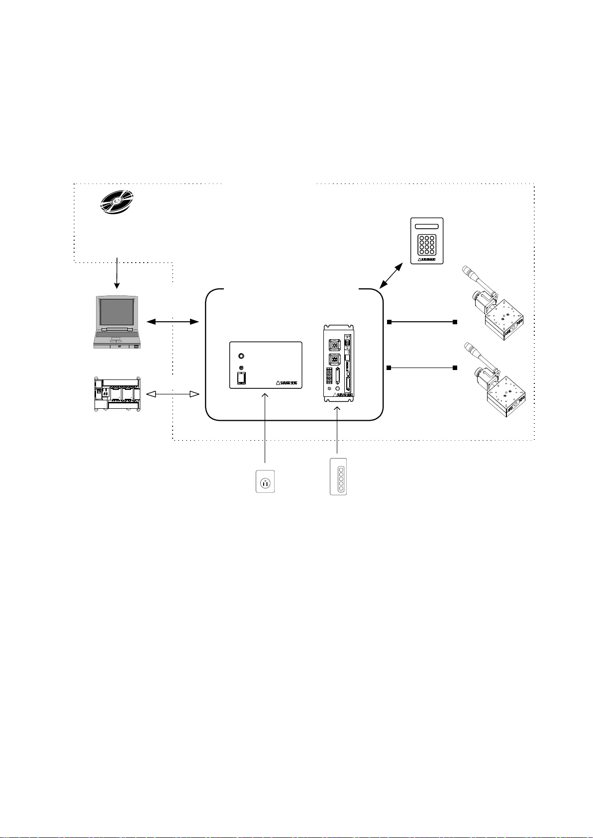
1.2 Product Outline / Features
Computer
PLC
DC24V
AC100V
XY
DS112
Stepping Motor Controller
DS112
Stepping Motor Controller
DS102/DS112 series
AC100~240V
DC24V
Motorized stage
DS102/112
Controlled software:
DSCONTROL-WIN
DS102
Stepping Motor
Controller
DS102
Suruga Seiki
Standard
DT100
Handyterminal
DT100
I/O for
controlled
USB
or
RS232C
DS102/DS112 series is stepping motor controller with 2 axes for not only R&D but also units and
manufacturing you can use what you want.
Product Outline
8
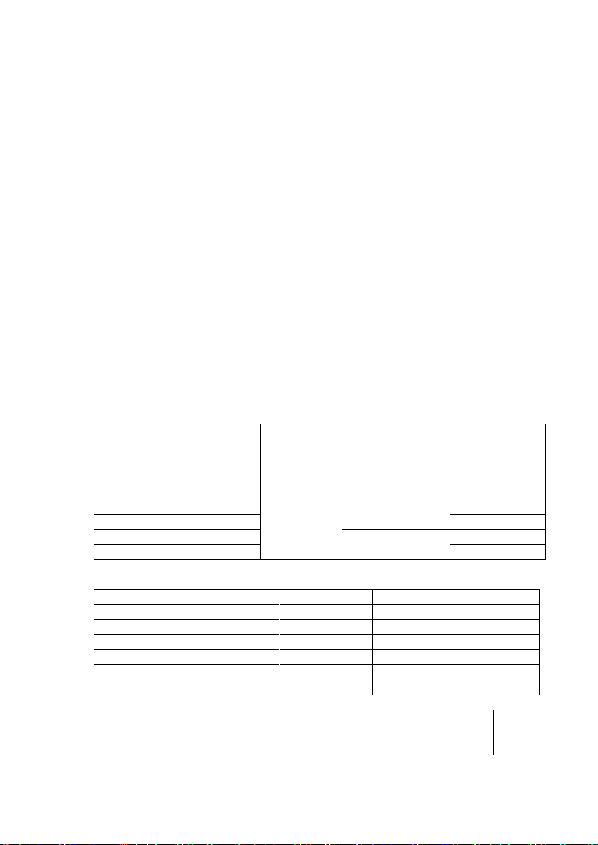
Features
SURUGA Type
MISUMI Type
Input PS
Type of Drive
General I/O
DS102NR
MSCTL102
AC100~240V
±10%
50/60Hz
Normal (FULL/HALF)
-
DS102NR-IO
MSCTL102-IO
Input16, Output12
DS102MS
MCSTL102-MS
Microstep (16levels)
-
DS102MS-IO
MSCTL102-IO-MS
Input16, Output12
DS112NR
MSCTL112
DC24V ±10%
Normal (FULL/HALF)
-
DS112NR-IO
MSCTL112-IO
Input16, Output12
DS112MS
MCSTL112-MS
Microstep (16levels)
-
DS112MS-IO
MSCTL112-IO-MS
Input16, Output12
SURUGA Type
MISUMI Type
Cable length
Recital
DS100-LINK2-0.5
MSLINK2-0.5
0.5m
For 2 links
DS100-LINK3-0.5
MSLINK3-0.5
0.5m
For 3 links
DS100-CNT-2
MSCNT2
2m
For control I/O(one end loose)
DS100-IO-2
MSGP2
2m
For general I/O(one end loose)
D100-R9-2
MSRS232C
2m
RS232C cable
DS100-USB-1.8
MSUSB1.8
1.8m
USB Cable
SURUGA Type
MISUMI Type
Article name
DT100
HDT100
Handy Terminal
DSCONTROL-WIN
MSSOFT
DS102/112 controlled software
1. Controlled
・ 5 phase stepping motor is controlled by 2 axes
・ Linear interpolation of 2 axes
・ 2 types motor driver with normal(FULL/HALF) and micro-step(16 levels)
As a microstep type, it is possible to highly positioning control and low vibration with
Smooth drive function.
・ It is possible to control 6 axes with link function.
Up to 24 axes can be controlled with USB Hub.
2. Drive
・ Teaching point movement
・ Program Drive
・ Jog Drive
・ It is possible to memorize teaching point 64 points and 8 of programs.
3. Interface
・ Connected USB、RS232C
・ DS102/112 controlled software:DSCONTROL-WIN
・ Handy terminal:DT100
・ I/O for controlled
・ General I/O:Input16points、output12points (Option)
・ 2 types of PS/V AC100~240V、DC24V
【Line up products】
【Option Cable】
【Other Option】
9
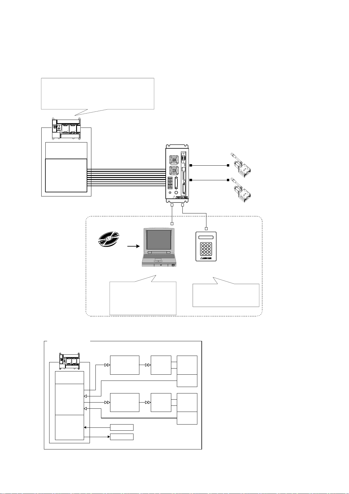
1.3 System configuration example
X axis
Motor driver
X axis motor
Guide ball
screw
Limit
Switch
Y axis
Motor driver
Y axis motor
Guide ball
screw
Limit
Switch
Position Control
Unit
CPU Unit
I/O Unit Sensor
Actuator
PLC
Former System
CPU Unit
I/O Unit
X Axis Stage
Y Axis Stage
PLC
XY
DS112
Stepping Motor Controller
DS112NR
Move the teaching point/Switch the program
drive
Teaching point number selected
Program number selected
Start/Stop
DS102/112
Controlled SoftWare:
DSCONTROL-WIN
・Move the teaching point/Switch the program drive.
・Teaching Point Number Selected.
・Program Number Selected
・Start
・Stop
・Set up the system parametor
・Memorized teaching points
・Programming and editing
・Operation check
・Back up data
PC
DT100
Handy Terminal
DT100
・Set up the system parametor
・Memorized teaching points
・Operation check
USB or RS232C
1.3.1 Control with PLC
Stages can be controlled with I/O units of PLC.
No need positioning units.
10
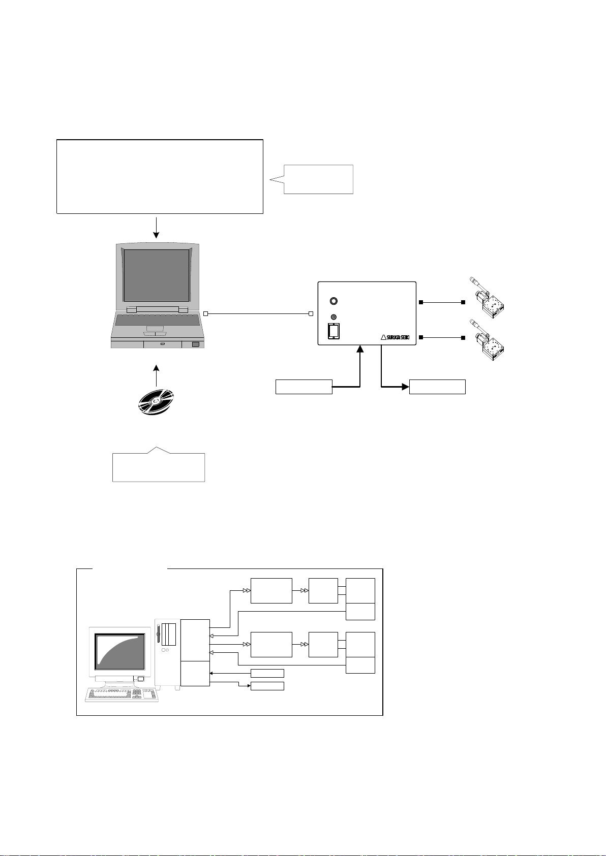
1.3.2 Controlled by PC
Motion
Control
Board
X Axis
Motor driver
X Axis
Motor
Guide
ball screw
Limit
Switch
Y Axis
Motor Driver
Y Axies
Motor
Guide
ball screw
Limit
Switch
I/O
Board
Sensor
Actuator
PC
Former set-up
Sensor Actuator
USB
or
RS-232C
X axis stage
Y axis stage
PC
General Input:
16points
General Output:
12points
DS102
Stepping Motor
Controller
DS102NR-IO
Use virtual COM port (Ex.:VB)
RS-232C communication application
MSComm1.Settings = "9600,N,8,1" ' Set up the port
MSComm1.CommPort = 1 ' Set up the port add.
MSComm1.PortOpen = True ' Open the port
' Move to 100 X axies
MSComm1.Output = "Axis1:Selsp 0:Goabs 100"
Original software
・Set up the system
parametor
・Operation check
・Cotrolled stage
・ControlI I/O
DS102/112
Control Software:
DSCONTROL-WIN
Easily controlled external machine by software.
No need motion control board and I/O board.
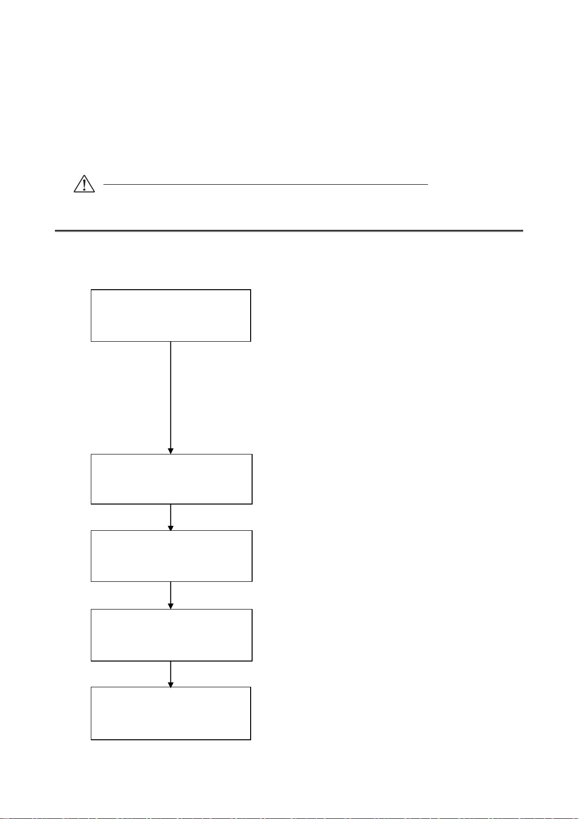
11
1.4 Accessories
Operation check
・DS102 or DS112
・X axis stage ・Y axis stage
・Motor cable
・RS232C cable:DS100-R9-2
・USB cable:DS100-USB-1.8
・Power cable
・PC
※You must have another power supply
and power cable if you use DS112.
・USB driver CD-R
・DSCONTROL-WIN CD-R (Option)
Conecting
Install USB driver
Set up the system parametor
DS102/112 Control soft ware:
Install DSCONTROL-WIN
This included following goods. Please check when you open. If some parts missing, please let us
know.
・ DS102/DS112:1 PCS
・ Power cable(2m) :1 PCS(Only case of DS102)
・ CD-R(data of this Manual , USB Device driver) :1PCS
・ Manual(this documents) :1PCS
The power cable of DS102 attachment is exclusively for this machine.
2.Set-up and example of use
2.1 Set up before use
Shows flow before use DS102/DS112.(MISUMI Type: MSCTL102/MSCTL112)

12
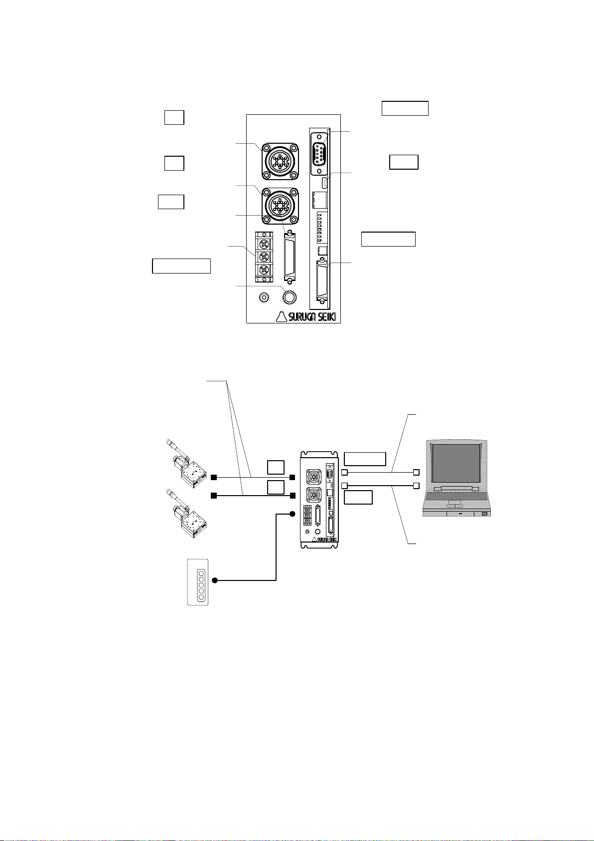
2.1.1 Connecting
I/O connector for
control
RS232C
X axis stage connector
General I/O
Connector
X Y
I/O
CNT-I/O EMS SW1 LINK USB RS232C
USB Connector
AC Inlet
Y axis stage connector
I/O
CNT-I/O
USB
RS232C
X
Y
TERMINAL
DS102
Stepping Motor Controller
Power
Connector for
Handy terminal
TERMINAL
Shows how to connect DS102/DS112
DS102

13
DS102
Stepping Motor
Controller
X axis stageY axis stage
AC100V
AC100
~240V
USB Cable:
DS100-USB-1.8
USBRS232C
RS232C Cable:
D100-R9-2
or
XY
Motor Cable
16 pins series stages:
D214-1-□E,D214-1-□R
(MISUMI:SRCB□,SRCB□-R)
12 pins series stages:
D214-2-□E,D214-2-□R
(MISUMI:MSCB□,MSCB□-R)
D214-2-□EA,D214-2-□RA
(MISUMI:MS4CB□,MS4CB□-R)
Attached
Power Cable
① Connect X axis motor connector to X axis stage.
② Connect Y axis motor connector to Y axis stage.
③ Connect AC inlet and AC100~240V.
④ Connect USB connector to USB port of PC.
(Connect RS232C connector to PC if use RS232C)
14
Use DS112
XY
TERMINAL
POWER
+24V
CNT-I/O EMS SW1 LINK USB RS232C
DS112
GNDFG
I/O
Y axis motor
connector
Terminal block for
power
General I/O
connector
Handy terminal
for connector
RS232C
connector
USB
connector
I/O connector for
control
Stepping Motor Controller
I/O
CNT-I/O
USB
RS232C
X
Y
TERMINAL
X axis motor
connector
X axis stage
Y axis stage
XY
DS112
Stepping Motor Controller
X
Y
USB cable:
DS100-USB-1.8
USB
RS232C
RS232C cable:
D100-R9-2
or
Motor cable
16pin series stage:
D214-1-□E,D214-1-□R
12pin series stage:
D214-2-□E,D214-2-□R
DC24V
DC24V
① Connect X axis motor connector to X axis stage.
② Connect Y axis motor connector to Y axis stage.
③ Connect terminal for power of DC24V to power supply(DC24V)
※ Must have DC24V power supply and cable
④ Connect USB connector to PC USB port.
(Connect RS232C connector to PC if use RS232C )
15
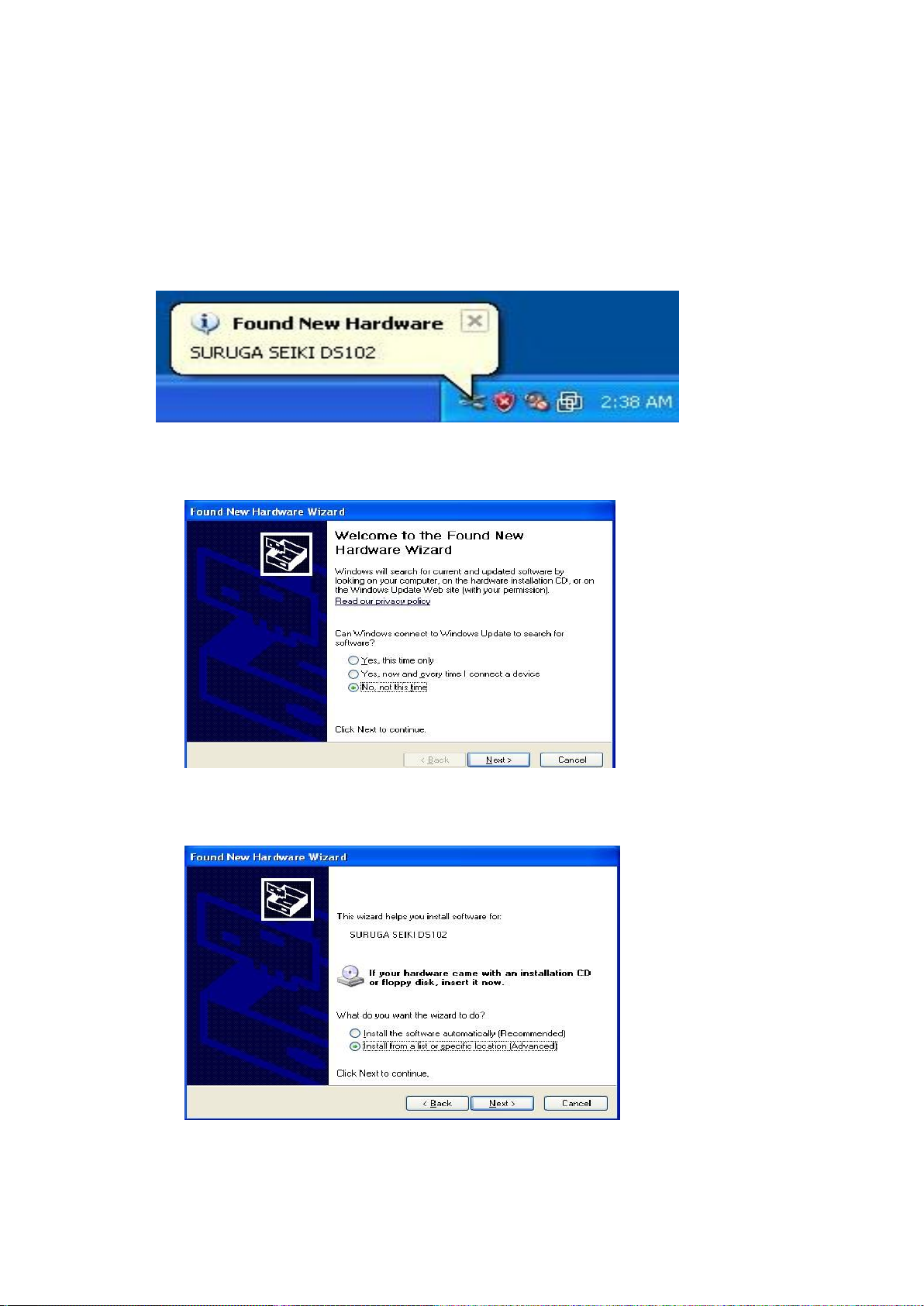
2.1.2 USB Driver Install
Shows how to install USB driver to PC(for XP).
① Switch on a computer and start Windows.
② Set up DS102/112 USB driver CD-ROM to computer drive.
③ Switch on DS102/112 and wait 5 seconds.
④ Connect computer USB port and DS102/112 USB connector.
When computer recognize to connect DS102/112, shows following messages.
⑤ At the detecting wizard of new hardware, choose [No, not this time]
and click [Next].
⑥ Select [Install from list or specific location (Advanced)] and click [Next].
16
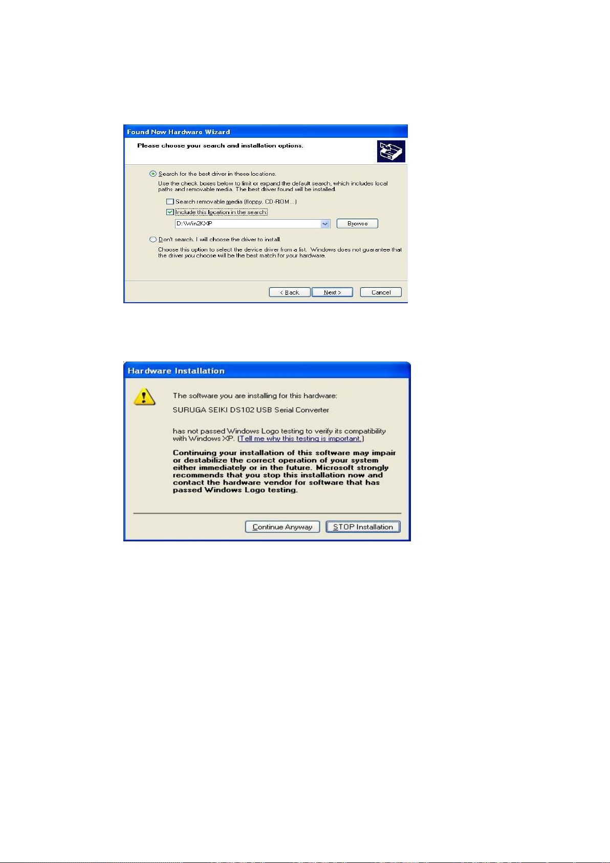
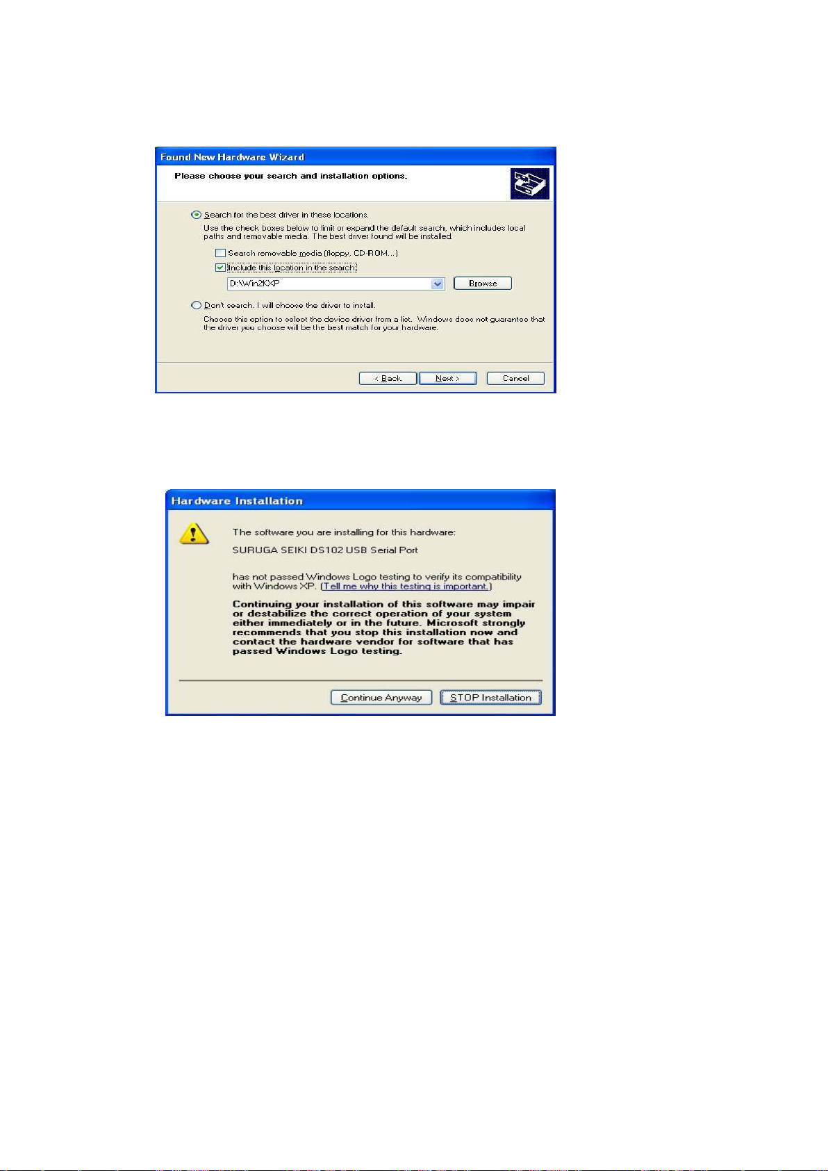
⑦ Check the [included this location in the search], push [Browse] and select [Win2KXP] then,
click [next].
Start the driver install.
⑧ Click the [Continue Anyway] when displays Hardware Installation.
17
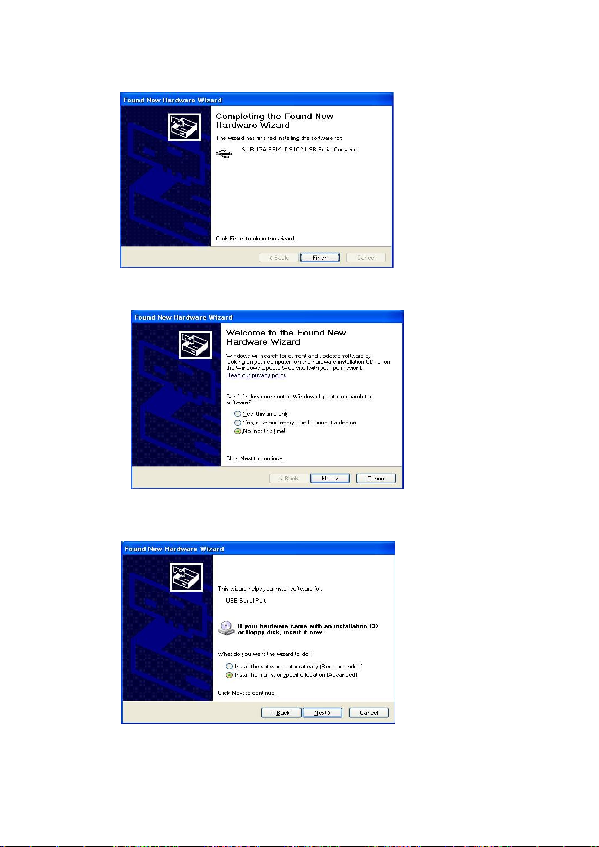
⑨ Click [finish]
Display the found new hardware wizard.
⑩ Select [No, not this time] and click [Next].
⑪ Select [Install from a list or specific location (advanced)] and click [Next].
18
⑫ Check the [included this location in the search], push [Browse] and select [Win2KXP] then,
click [next].
Start the driver install.
⑬ Click the [Continue Anyway] when displays Hardware Installation.

19
⑭ Click [finish]
Display the found new hardware wizard.
2.1.3 Installation for control software DS102/112(DSCONTROL-WIN)
Show how to install software (DS CONTROL-WIN) to control DS102/112 by PC.
① Insert CD-ROM of DSCONTROL-WIN inside PC drive.
② Double click on setup.exe in CD-ROM.
DSCONTROL-WIN installer start.s.
③ Click [next]
The screen below appears on PC.
20
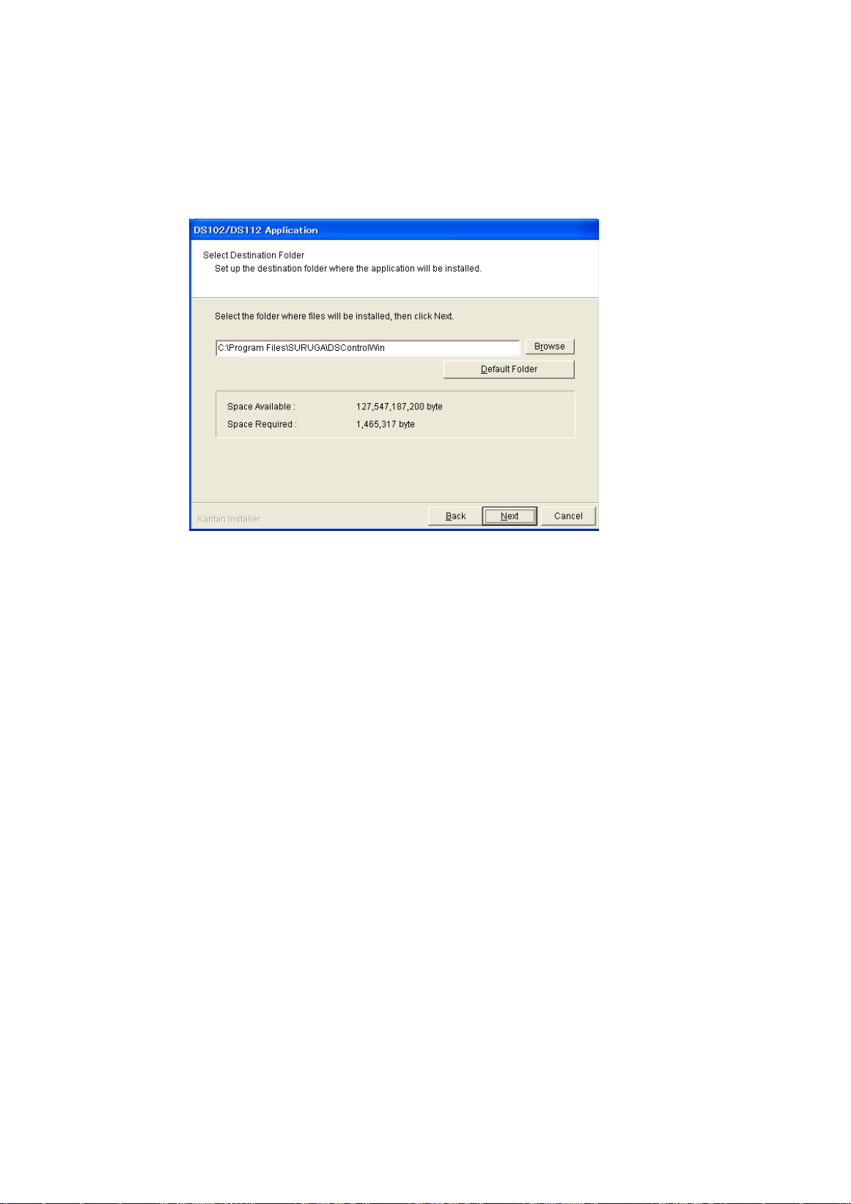
④ Select folder of installation then click {Next}
The screen shows folder selection
※On initial setting, installation folder is:\Program Files\SURUGA\DSControlWin.
Click [Next] in case of no required folder
21
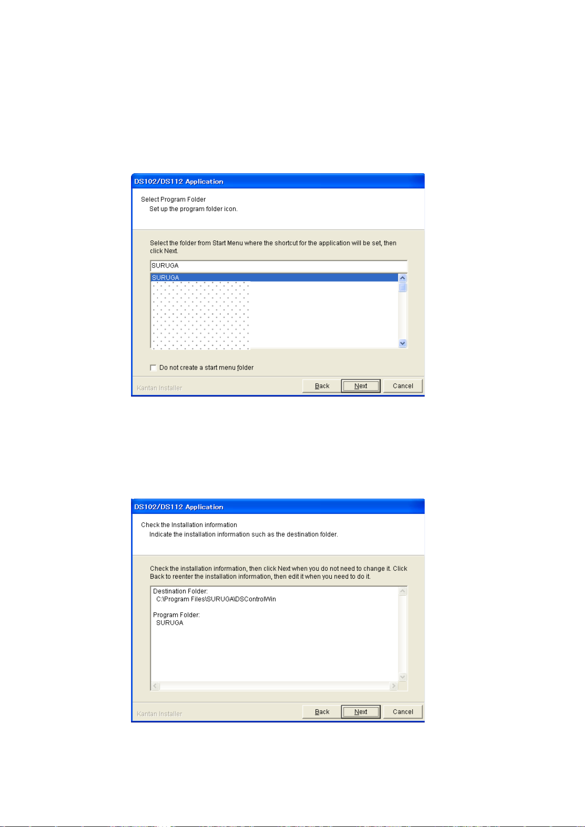
⑤ To prepared Program Shortcut, you need to select folder from list on START MENU then click
[Next]
The drawing below appears on PC screen
※On initial setting, Startmenu folder is DSControlWin.
Click [Next] in case of no required folder
⑥ Click [Next] after you confim installed contents
The screes scomes to [Information]
22
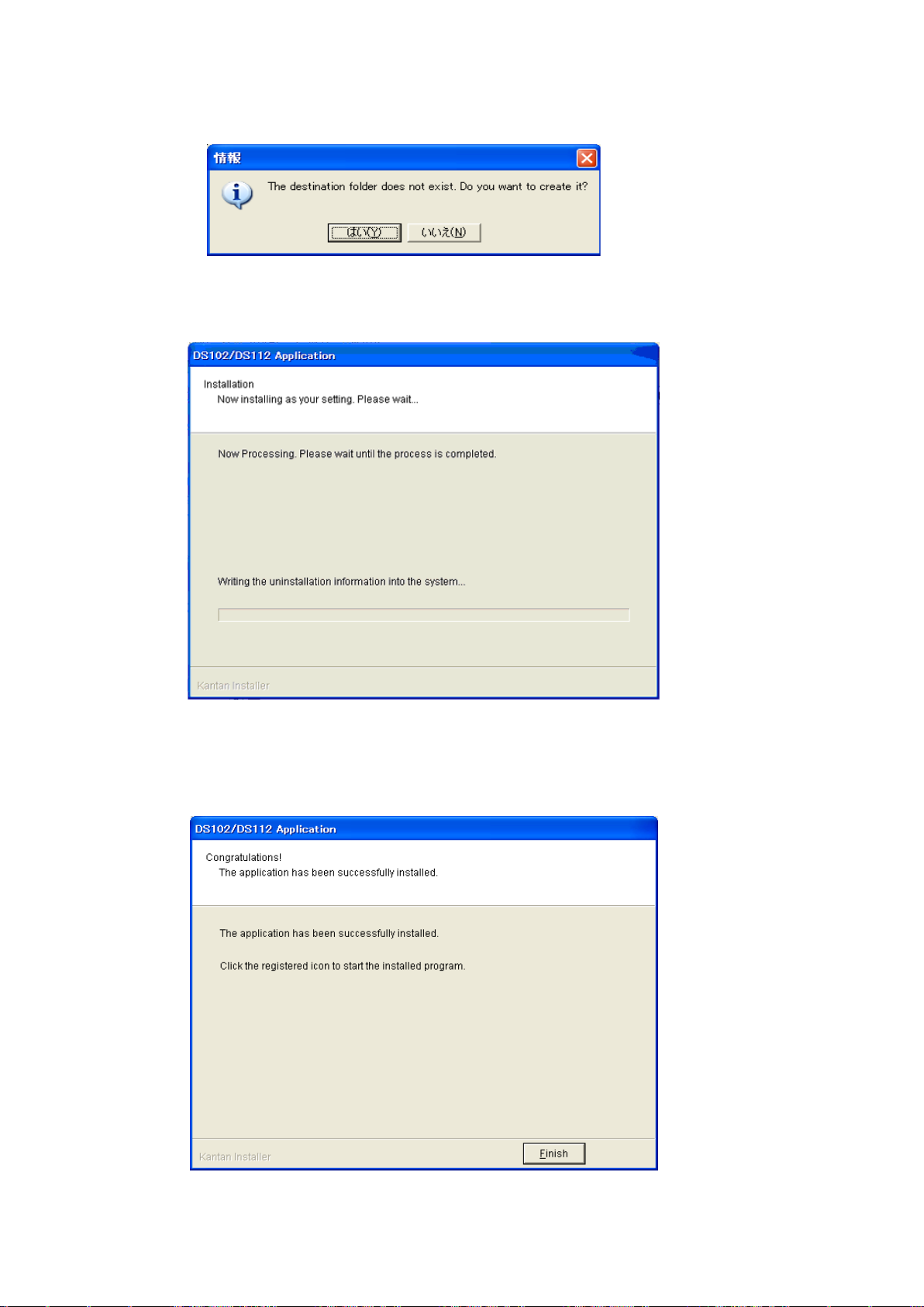
⑦ Click [YES]
※ No pop-up message appears if you already select folder
Installation begins
Installation complete.
⑧ Click [Finish]
Installing DSCONTROL-WIN completed.
23
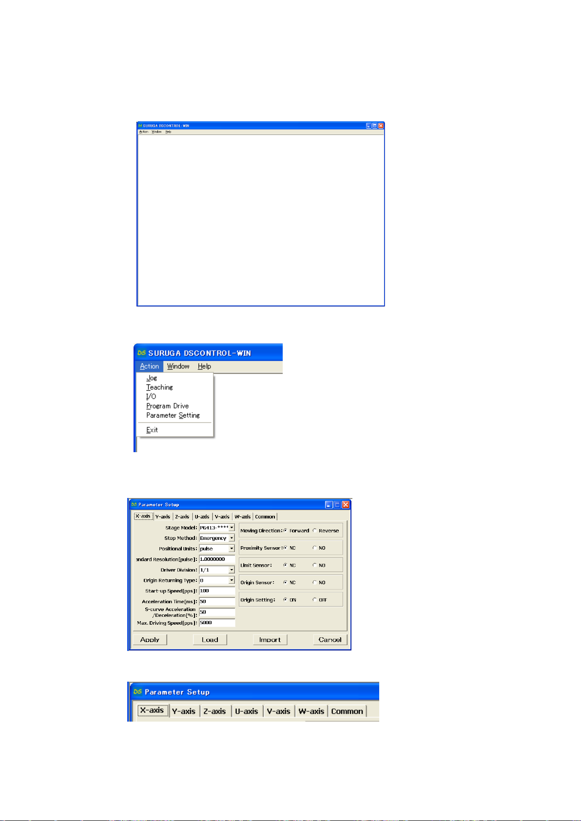
2.1.4 Adjustment system parameter
Shows how to set up system parameter by DSCONTROL-WIN
① Starts DSCONTROL-WIN
② Select [Parameter setting] in [Action]
Parameter setting appears on screen
③ Click on Tab you sellect
24
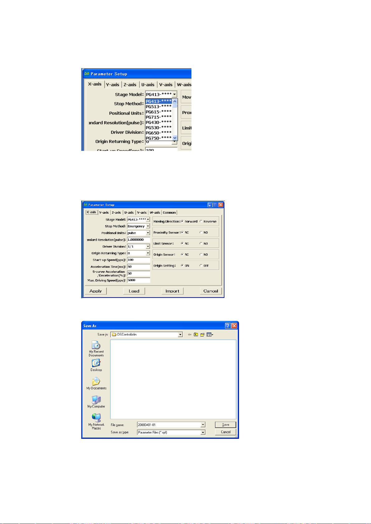
④ Select stage model you use from [Stage Model]
Initial value appears when you select stage model.
※ input direct value if we want to change initial value.
⑤ Select axis parameter by repeating ③~④ again.
⑥ Click [Apply].
Screen shows folder storing parameter.
⑦ Select folder and input file name then click [Save].
Parameter values are saved PC then forward values toward DS102/112.
※ Spf is automatically added.
25
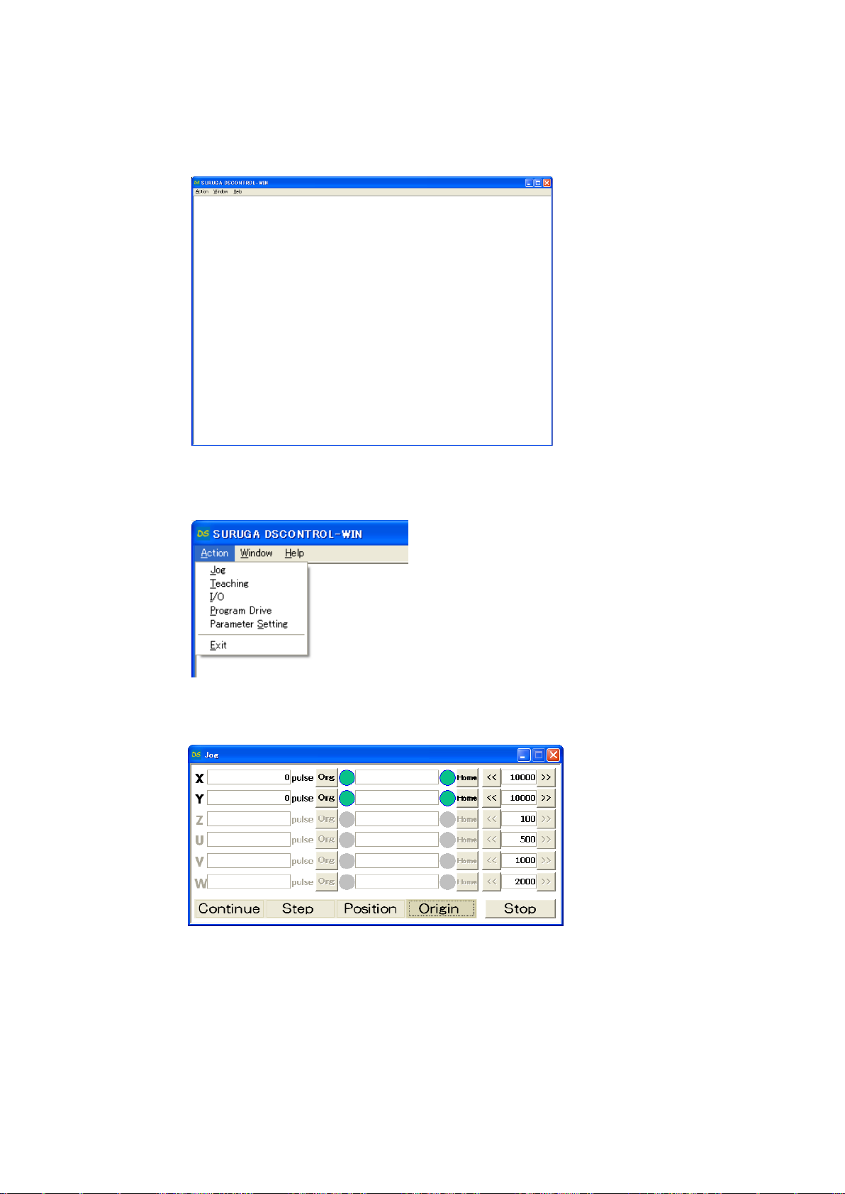
2.1.5 Operation check
Shows how to check operation.
① Starts DSCONTROL-WIN.
② Click [JOG] in [Action] on main menu
JOG dialog appears on screen.
③ Click [Origin]
[Org],[Home] appears.
④ Click [Org] on X axis
X stage return origin position.
Make sure X stage moves origin position.
⑤ Repeat ③~④ again Y axis return to origin position.
26
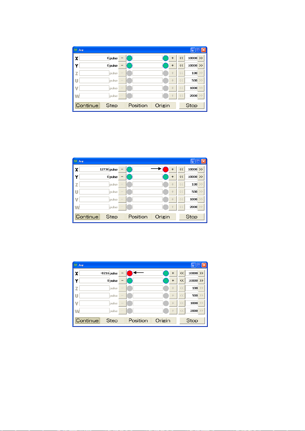
⑥ Click [Contiue]
[+],[-]appear on screen.
⑦ Keep clicking [+] on X axis
X stage moves toward CW direction.
Stage stops when it reachs to CWLS then indicator leftside [+] becomes RED.
⑧ Keep clicking [-] on X axis
X stage moves toward CCW direction.
Stage stops when it reachs to CCWLS then indicator rightside [-] becomes RED.
⑨ Repeat ⑦~⑧ on Y axis.
27
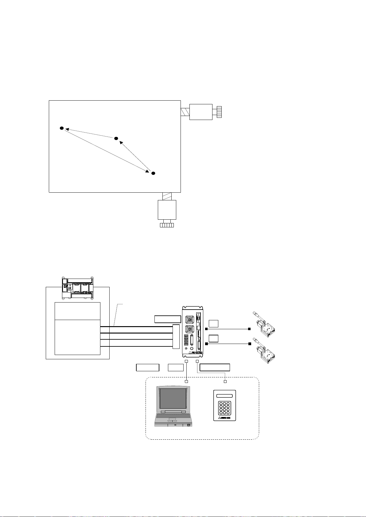
2.2 System architecture
Waiting posi
(50,100)
Working posi
(1000,1500)
Exporting Posi
(2000,3000)
X axis stage
CPU unit
I/O unit
Y axis stage
PLC
XY
DS112
Stepping Motor Controller
DS112
T_BIT0~5
P/T_START
STOP
PRG/TCH
CNT-I/O
I/O cable
DS100-CNT-2
PC
DT100
Handy Terminal
DT100
USB
TERMINAL
X
Y
RS232C or
STEP1 : Moving to waiting position (50,100)
STEP2 : Moving to working position (1000,1500)
STEP3 : Processing on target
STEP4 : Moving to exporting position (2000,3000)
STEP5 : Exporting processig
2.2.1 Movement between each teaching position
Show how to set up position inside memory of DS112 (MISUIMI Type: MSCTL112)and move its
position by PLC.
1) Configuration
※ CNT-I/O shows following signal. READY means Waiting condition of DS112 and X_DRIVE and
Y_DRIVE means both working condition. P/T_RUN means Teaching working and Program
working.

28
2) Movement summary
Waiting, working and exporting position memorized inside DS112 as teaching points, 00, 01, 02,
PLC appoints each points then make state move to each points.
① Set up 00 among T_BIT0~5, press P/T_START <STEP1>
② Set up 01 among T_BIT0~5, press P/T_START <STEP2>
③ Wait unitl woring on target is done <STEP3>
④ Set up 02 among T_BIT0~5, press P/T_START <STEP4>
⑤ Wait until exporting is done <STEP5>
3) Connect
Connect to DS112
PC is used when setting or editing teaching point
① Connect USB to PC USB port
(Connect RS232C to PC when using RS232C)
② Connect handy terminal to DS112
③ Connect X axis motor connector to X stage
④ Connect Y axia motor connector to Y stage
⑤ Connect control I/O connector to PLC I/O unit
On control I/O,
T_BIT0~5:Appoint teaching point
P/T_START:Signal to move to teaching point
STOP:Stop signal for all axes
PRG/TCH:program mode / teaching point mode
※ T_BIT0~2:combined use for program selection
29
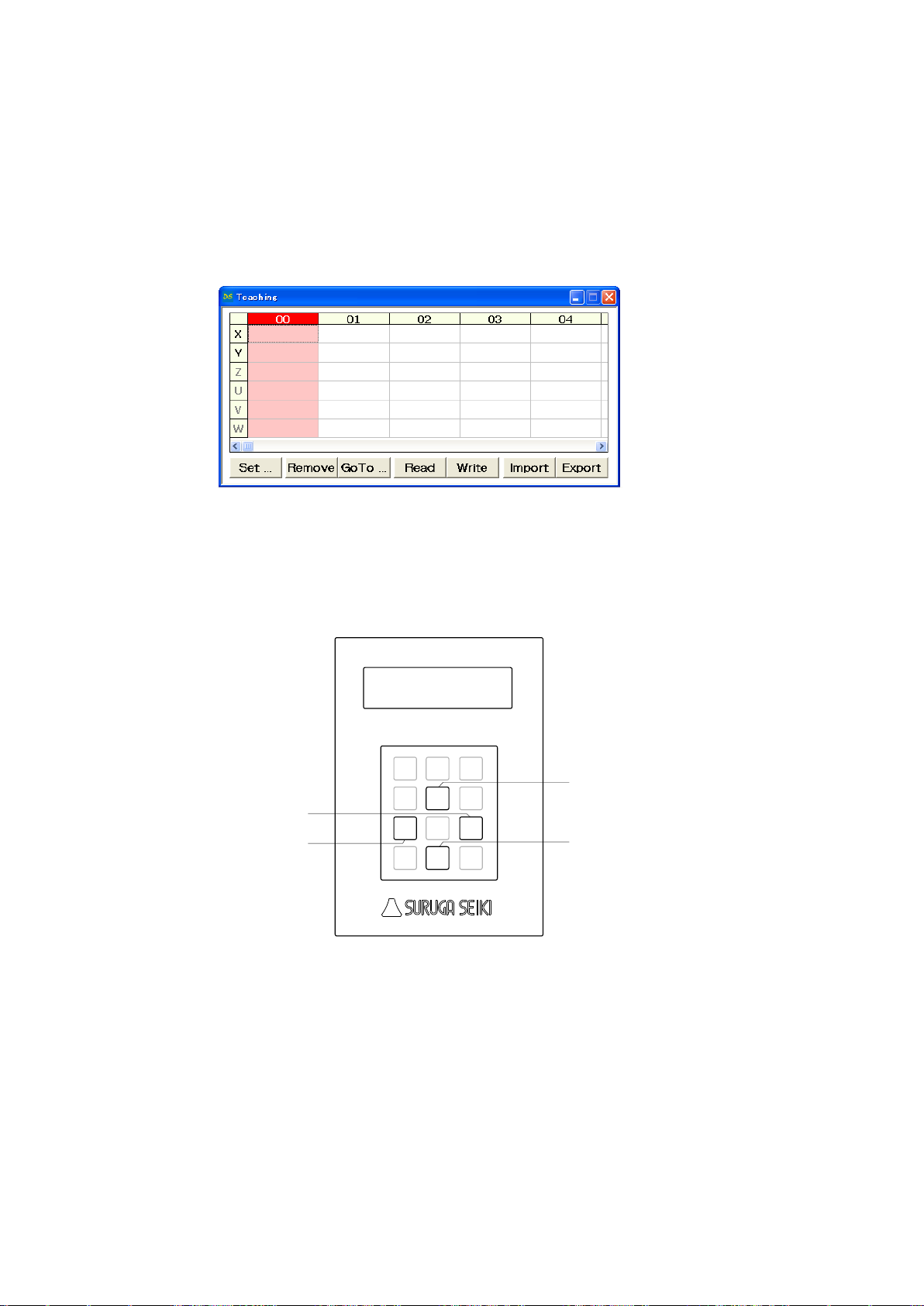
4) Memory of teaching point
Jog
7
Menu8Set
9
SPD
4
↑
5
POS
6
←1Link
2
→
3
Stop
0
/ESC
DT100
Handy Terminal
↓
.-
Enter
X stage CCW direction
X stage CW direction
Y stage CCW direction
Y stage CW direction
Memorizing teaching point inside DS112
① Start DSCONTROL-WIN
② Select [Teaching] on main menu in DSCONTROL-WIN.
Screen below appears.
③ Push direction key on handy terminal unitl stage moves to specific positon.
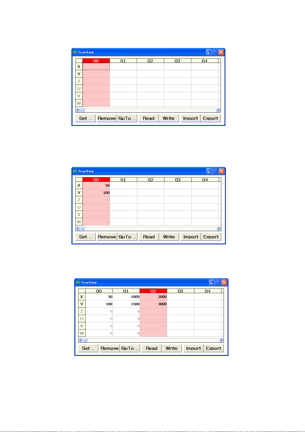
30
④ Click [00] CELL on the teacing screen
00 CELL gets to be Red.
⑤ Click [Set]
Current stage position as 00 is memorized to DS112.
⑥ Repeat ③~⑤ so memorize 01 as working position and 02 as exporting position to DS112.
 Loading...