

MISUMI IP-1614GII Instructions Manual

Device manual of IP Cameras
Page 1 of 29
!
!
IP-1614GII
IP Cameras Products Series
User Manual &
Installation Guide
Version: 1.0
Date: March 2, 2006

Device manual of IP Cameras
Page 2 of 29
Table of Contents
TABLE OF CONTENTS.......................................................................................................................... 2
WHAT IS IP CAMERAS? ....................................................................................................................... 3
PRODUCT FEATURES............................................................................................................................3
2. PHYSICAL CONNECTIONS..............................................................................................................4
3. INSTALLATION.................................................................................................................................. 4
CONNECT IP CAM TO NETWORK .........................................................................................................6
CONNECT POWER SUPPLY...................................................................................................................6
HOW TO RESET .................................................................................................................................... 6
START YOUR FIRST TIME NETWORK MONITORING .............................................................................7
HOW TO VISIT THE BUILT-IN WEB........................................................................................................8
ABOUT THE USER INTERFACE OF IP CAM ..........................................................................................9
HOW TO CHECK THE FIRMWARE VERSION.......................................................................................... 9
HOW TO CHANGE THE CONFIGURATIONS..........................................................................................10
HOW TO CHANGE USER LOGO ..........................................................................................................12
HOW TO DISABLE AND ENABLE USER LOGO ......................................................................................15
USER MANAGEMENT .........................................................................................................................16
LOG .................................................................................................................................................... 17
NETWORK ..........................................................................................................................................18
VIDEO................................................................................................................................................. 19
EVENT ................................................................................................................................................20
4. PRODUCT SPECIFICATIONS ......................................................................................................... 23
MODELS .............................................................................................................................................23
SPECIFICATIONS:...............................................................................................................................23
5. APPENDIX ........................................................................................................................................25
DICTATION .........................................................................................................................................25
USE CGI COMMAND TO SETUP GPIO AND EVENTS .........................................................................27
How to configure GPIO Process? ............................................................................................... 27
How to Configure Event Process ................................................................................................27
SCENARIO: USE DI TO TRIGGER EVENT AND SEND IMAGES THROUGH MAIL AND FTP.................. 28
Turn FTP Service on the server ..................................................................................................28
Enable DI status to “ON”............................................................................................................28
Turn On FTP and Email ..............................................................................................................29
Setup Event status........................................................................................................................29
Check DI type status....................................................................................................................29
Check Event Status ...................................................................................................................... 29
Click on DI and you can check your mail box and FTP services .............................................29

Device manual of IP Cameras
Page 3 of 29
1. Product Overview
What is IP Cameras?
IP Cameras is designed for intranet & internet use. Users can view image or change
configurations via built-in web server. The two-layer user-validation prevents any
illegal user to monitor or change configuration once user validation is enabled
Product Features
IP Cameras CPU: 32 Bits RISC Processor. 16Mb Flash, 64Mb SDRAM
Linux OS
TCP/IP network remote Video transmission system
High performance JPEG/MJPEG compression
Built-in Web sever
Built-in DHCP Client
Built-in Motion Detection
Frame Rate Control
Administrator / User level password protection
Snapshots
On-line firmware upgrade
Frame Rate: NTSC: 30 frame/sec
Device manual of IP Cameras
Page 4 of 29
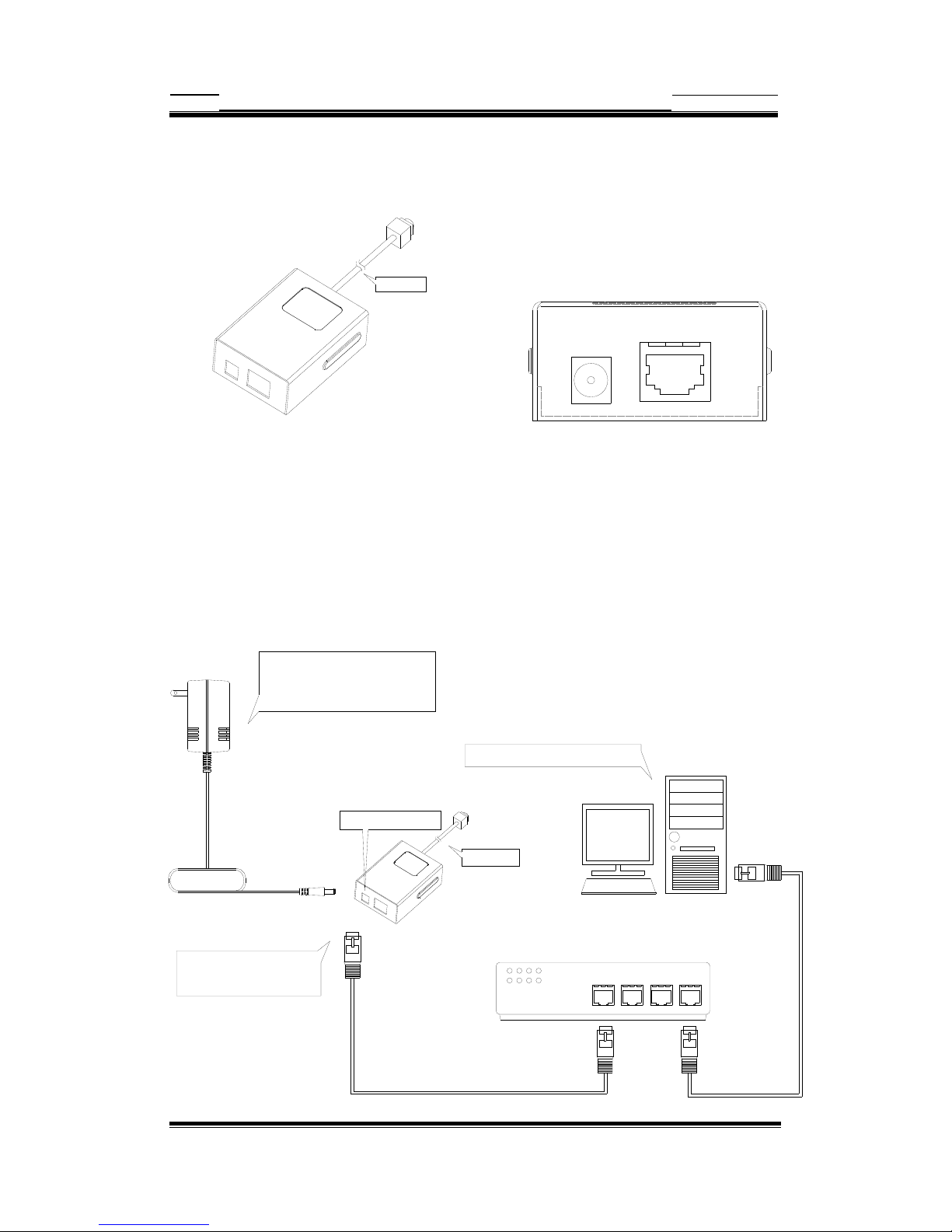
2. Physical Connections
W/100cm cable
DC 12V
INPUT
Ethernet
Side Panel Connections Front Panel Connections
IP-R1614GII
3. Installation
Connect Power Supply DC 12V
Ensure your power adapter specifi cation
matchs your power system (ex 110V or 220V)
Connect the adapter to the outlet.
Once the power status is OK. the
LED in red located at the re ar panel
of IP cam should light-up.
Connect power jack
Prepare a PC to link your netw ork with Ethernet
W/100cm cable

Device manual of IP Cameras
Page 5 of 29
Network connectivity check
Please check your network connectivity before you start install the product.
Confirm the link status of your LAN is OK. You may try use the following way to
check the network.
Assuming you are under Microsoft Windows 2000 desktop, Click on Start button,
Programs, Accessories, Command Prompt
Δ
Then there will be a blank window
appear to wait command input. Please key in the following command to test the
network status.
C:\>ping 192.168.1.1 [Enter]
*Note: the target IP address given above may be correct in common scenarios, if
your network is not configured by IP segment 192.168.1.x, please change the IP
Address to a valid address in your local network. Any difficulties please contact
your network administrator for assistance.
If your network status is OK, the result of above command should like following
Pinging 192.168.1.1 with 32 bytes of data:
Reply from 192.168.1.1 bytes=32 time=10ms TTL=64
…
If you have confirmed your network connectivity is OK, Please proceed to next part
of installation guide, otherwise, contact your network administrator to recover the
problem.

Device manual of IP Cameras
Page 6 of 29
Connect IP cam to network
Once the power status is OK.the
LED in red located at the rear panel
of IP cam should light-up.
W/100cm cable
Connect IP cam to your hub/switch by using a normal RJ45 cable, plug the RJ45
cable into the Ethernet connector locate at the rear panel of the IP cam, another
side connect to your hub/switch.
Connect Power Supply
Connect power jack
W/100cm cable
Connect Power Supply DC 12V
Ensure your power adapter specification
matchs your power system (e x 110V or 220V)
Connect the adapter to the outlet.
Connect the IP cam and power source with the adapter provided, plug the power
adapter into the DC 12V Connector. Once the power status is OK, the LED in red
located at the rear panel of IP cam should light-up.
How to reset
Load IP Cam Default Settings
DC 12V
INPUT
Ethernet
Device manual of IP Cameras
Page 7 of 29
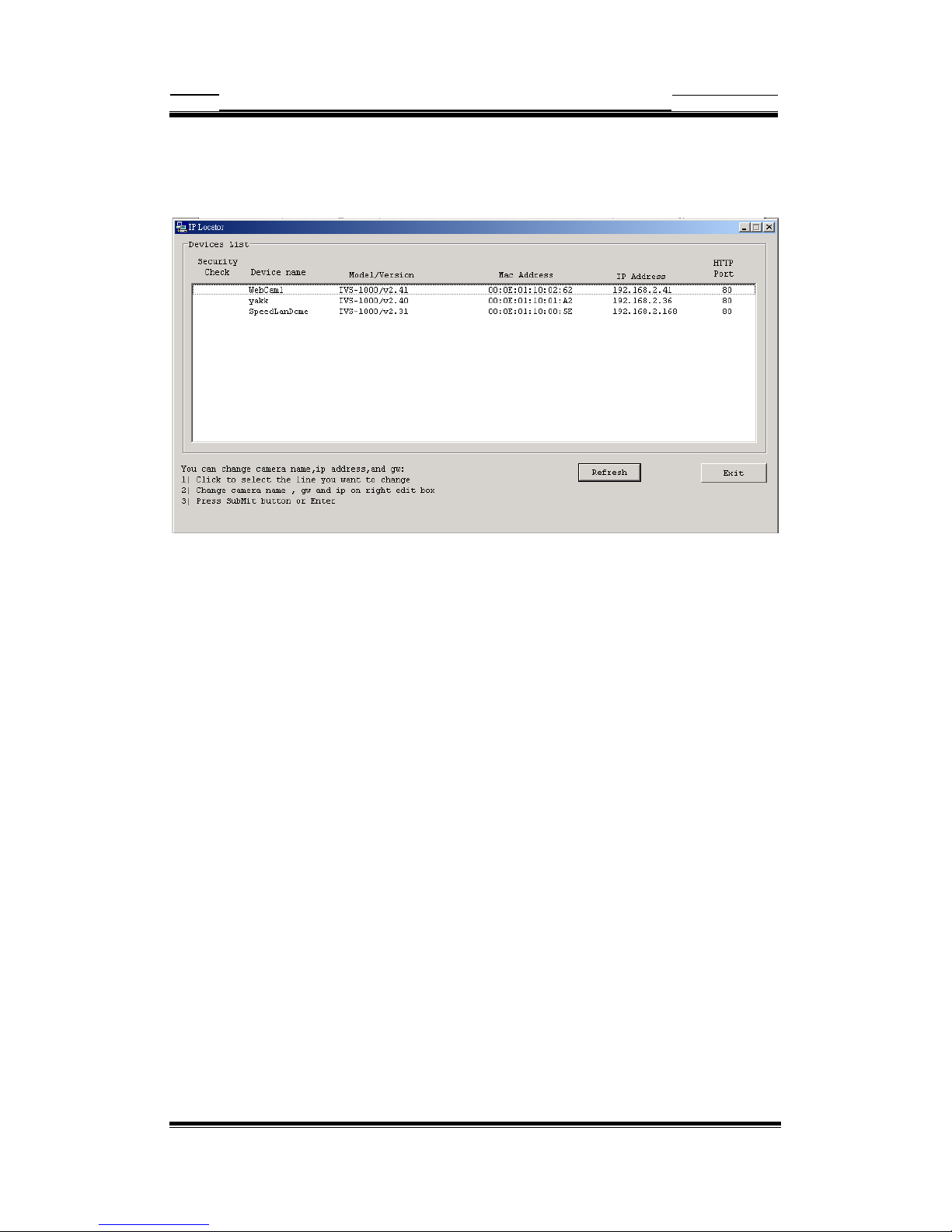
Start your first time network monitoring
Run the “IPLocator” utility, the newly connected IP cam will be listed in the
application window. Please remember its’ IP address.
Open an Internet Explorer Window input the following address into the address
textbox:
http://[IP cam IP Address provided by IPLocator]
After you press on the enter key, the main working interface and video picked by
the camera should appear after a short period. The installation steps are completed.
You may now start your first network monitoring experience.
Note: when you first time enter the working interface, the browser may ask whether
to install a COMWebSurv component, which is used to communicate with our IP
cam product, PLEASE CHOOSE YES to install, otherwise the monitoring function
may not work.
Device manual of IP Cameras
Page 8 of 29
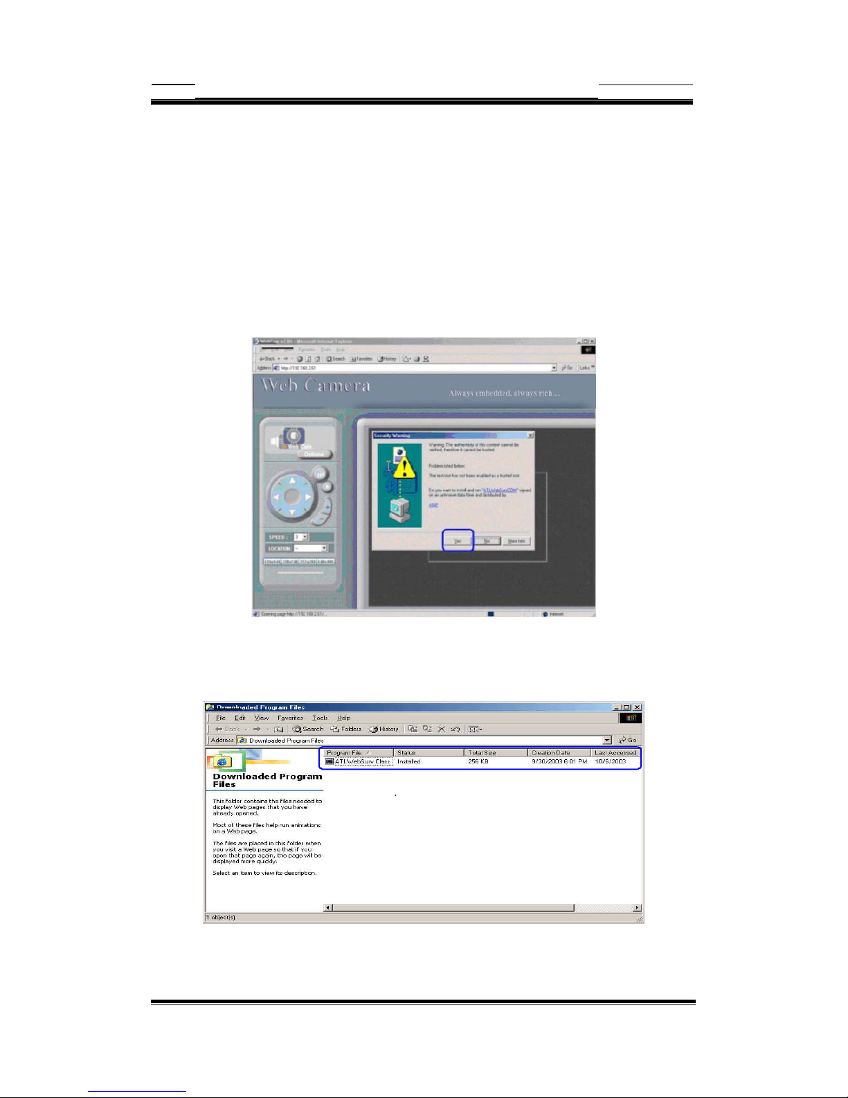
How to visit the built-in web
Launch your Internet Explorer (I.E. 6.0 or above) first, then type the IP cam’s url. (i.e.
http://192.168.1.100). The user validation is disabled as default, no login is necessary. The
user is same as the system administrator(Default : root/pass).
For the first time user visits the IP Cam, the ActiveX(ATLWebSurvCOM) will be downloaded to
the [Downloaded Program File]. Be sure to click the button [Yes] as below.
Notes: Call your system administrator if you have not enough privilege to download the
ActiveX. (i.e. Users should be the administrator to download the ActiveX for Windows 2000/XP
operation system)
You can find the ActiveX ATLWebSurvCOM will be downloaded to the [Downloaded
Program File] folder. The above dialog will pop automatically once new ActiveX is
available(i.e. after firmware upgrade)

Device manual of IP Cameras
Page 9 of 29
About the User Interface of IP Cam
The upper window is for company logo display (i.e. This is a generic version. The
company logo leaves blank). The left side of the window is the control panel. The
right window is for image display. (Please switch to full screen mode when the
resolution is set to VGA mode)
How to check the firmware version
Click the WebCam icon and you will read the firmware version
 Loading...