

MISUMI IESH-MB205-R Installation Manual

Misumi EtherDevice Switch
MISUMI EtherDevice スイッチ
IESH-MB205-R Hardware Installation Guide
IESH-MB205-R ハードウェア・インストール・ガイド
Second Edition, July 2012
第 2 版、2012 年 7 月
P/N: 1802002050211
2012 Misumi, all rights reserved.
Reproduction without permission is pr
ohibited.
許可なく複製することを禁止します。
- 2 -
Overview
The IESH-MB205-R switches are entry-level 5- port Ethernet switches that
provide a cost-effective solution for your industrial Ethernet connection.
You could choose either a DC power input from 12 to 48 V or AC power input
from 18 to 30 V. These switches can operate from -10 to 60
o
C, and the rugged
hardware design makes the IESH-MB205-R switches perfect for ensuring that
your Ethernet equipment can be used for demanding industrial applications.
This device complies with part 15 of the FCC Rules. Operation
is subject to the following two conditions: (1) This device may
not cause harmful interference, and (2) this device must accept
any interference received, including interference that may cause
undesired operation.
Package Checklist
The IESH-MB205-R is shipped with the following items. If any of these items
is missing or damaged, please contact your customer service representative for
assistance.
IESH-MB205-R Switch
Hardware Installation Guide

- 3 -
Panel Layout of the IESH-MB205-R
Series
1. Heat dissipation orifices
2. Terminal block for power input
and grounding
3. Misumi logo
4. Power input LED
5. 10/100BaseT(X) Port
6. TP port’s 100 Mbps LED
7. TP port’s 10 Mbps LED
8. DIN-Rail kit
- 4 -
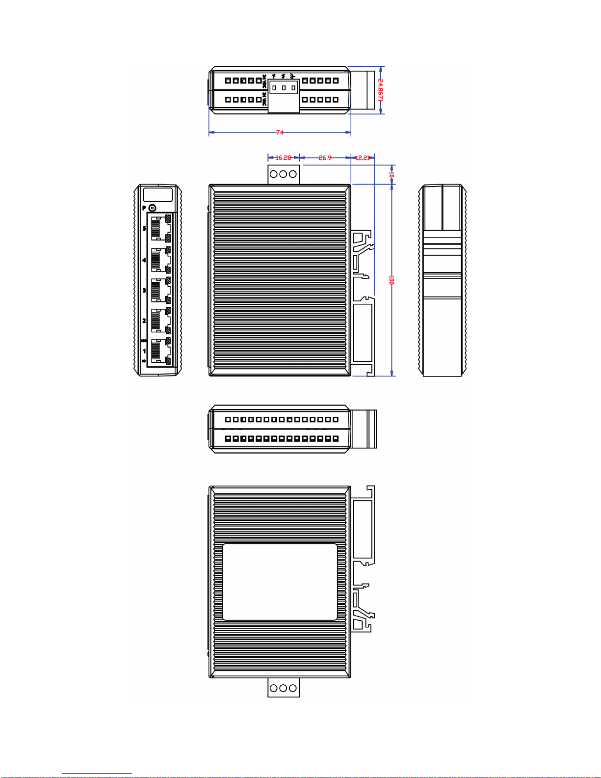
Mounting Dimensions
- 5 -
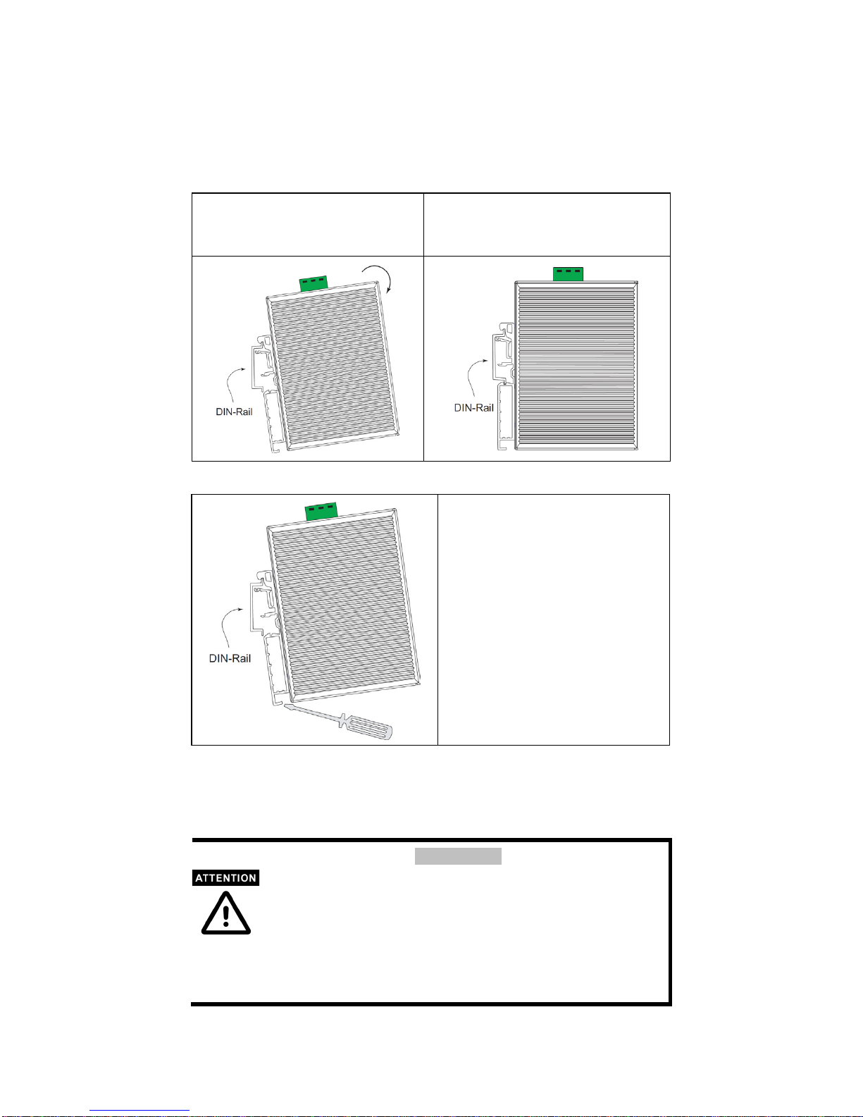
DIN-Rail Mounting
The plastic DIN-Rail attachment plate should already be fixed to the rear panel
of the EDS when you take it out of the box. If you need to reattach the
DIN-Rail attachment plate, make sure the DIN-Rail kit is situated towards the
top, as shown in the figures below.
STEP 1:
Insert the top of the DIN-Rail into
the slot.
STEP 2:
The DIN-Rail attachment unit will
snap into place as shown below.
To remove the IESH-MB205-R from
the DIN-Rail, insert a flat-blade screw
driver horizontally into the DIN-Rail
kit under the IESH-MB205-R, and
then pull it upwards and release the
switch towards you and away from
the DIN-Rail.
Wiring Requirements
Safety First!
Be sure to disconnect the power cord before installing and/or
wiring your
EtherDevice Switch.
Cal
culate the maximum possible current in each power wire and
common wire. Observe all electrical codes dictating the
maximum current allowable for each wire size.
If the current goes above the maximum ratings, the wiring could
overheat, causing serious damage to your equipment.
- 6 -
You should also pay attention to the following points:
Use separate paths to route wiring for power and devices. If power wiring
and device wiring paths must cross, make sure the wires are perpendicular
at the intersection point.
NOTE: Do not run signal or communications wiring and power wiring in
the same wire conduit. To avoid interference, wires with different signal
characteristics should be routed separately.
You can use the type of signal transmitted through a wire to determine
which wires should be kept separate. The rule of thumb is that wiring that
shares similar electrical characteristics can be bundled together.
Keep input wiring and output wiring separated.
It is strongly advised that you label wiring to all devices in the system when
necessary.
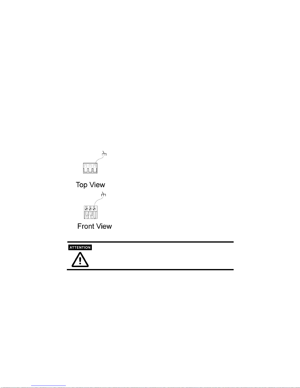
Grounding the EtherDevice
Switch
Grounding and wire routing help limit the effects
of noise due to electromagnetic interference
(EMI). Run the ground connection from the right
most contact of the 3-
contact terminal block to the
grounding surface prior to connecting devices.
This product is intended to be mounted to a well-grounded
mounting surface such as a metal panel.
 Loading...